WO2019031059A1 - Chuck correction method - Google Patents
Chuck correction method Download PDFInfo
- Publication number
- WO2019031059A1 WO2019031059A1 PCT/JP2018/022862 JP2018022862W WO2019031059A1 WO 2019031059 A1 WO2019031059 A1 WO 2019031059A1 JP 2018022862 W JP2018022862 W JP 2018022862W WO 2019031059 A1 WO2019031059 A1 WO 2019031059A1
- Authority
- WO
- WIPO (PCT)
- Prior art keywords
- front body
- axis
- chuck
- rear body
- bolt
- Prior art date
Links
Images


Classifications
-
- B—PERFORMING OPERATIONS; TRANSPORTING
- B23—MACHINE TOOLS; METAL-WORKING NOT OTHERWISE PROVIDED FOR
- B23B—TURNING; BORING
- B23B31/00—Chucks; Expansion mandrels; Adaptations thereof for remote control
- B23B31/02—Chucks
- B23B31/36—Chucks with means for adjusting the chuck with respect to the working-spindle
-
- B—PERFORMING OPERATIONS; TRANSPORTING
- B23—MACHINE TOOLS; METAL-WORKING NOT OTHERWISE PROVIDED FOR
- B23B—TURNING; BORING
- B23B31/00—Chucks; Expansion mandrels; Adaptations thereof for remote control
- B23B31/02—Chucks
- B23B31/10—Chucks characterised by the retaining or gripping devices or their immediate operating means
- B23B31/12—Chucks with simultaneously-acting jaws, whether or not also individually adjustable
- B23B31/16—Chucks with simultaneously-acting jaws, whether or not also individually adjustable moving radially
- B23B31/16045—Jaws movement actuated by screws and nuts or oblique racks
-
- B—PERFORMING OPERATIONS; TRANSPORTING
- B23—MACHINE TOOLS; METAL-WORKING NOT OTHERWISE PROVIDED FOR
- B23B—TURNING; BORING
- B23B31/00—Chucks; Expansion mandrels; Adaptations thereof for remote control
- B23B31/02—Chucks
- B23B31/10—Chucks characterised by the retaining or gripping devices or their immediate operating means
- B23B31/12—Chucks with simultaneously-acting jaws, whether or not also individually adjustable
- B23B31/16—Chucks with simultaneously-acting jaws, whether or not also individually adjustable moving radially
- B23B31/16004—Jaws movement actuated by one or more spiral grooves
- B23B31/16033—Jaws movement actuated by one or more spiral grooves with a centre
Definitions
- the present invention relates to a method of correcting a chuck used in a machine tool.
- on-machine molding of jaws is performed.
- the gripping surface of the jaw is processed while grasping the forming plug so that the center of rotation of the chuck and the center of the work coincide with high accuracy.
- the grasping surface of the jaw is processed while grasping the forming plug on the chuck body side more than the workpiece grasping surface of the jaw, the position of the grasping surface and the position for grasping the forming plug are different. Therefore, when the workpiece is actually grasped, the workpiece center may be slightly shifted from the rotation center of the chuck.
- Patent Document 1 shows an example in which a drawbar for attaching a jaw is grasped by a forming plug, and the tip of the drawbar is formed.
- the forming plug grasping portion is provided on the draw bar
- the jaws are separated from the chuck body in front of the axis of the chuck.
- the center (core) of the work is easily displaced from the rotation center (axis) of the chuck.
- An object of the present invention is to improve the accuracy of matching the center (core) of a work with the rotation center (axis) of a chuck.
- a chuck correction method comprising a correction step, wherein the chuck comprises a body, a plunger, and a jaw, the body being a rear body and a front disposed on the front side of the rear body.
- the plunger is provided in the body and configured to move on an axis of the body, and the jaw is guided by the movement of the plunger to the front body to center the axis.
- the front body is configured to move in the radial direction, and in the correction step, when the jaw is made to grasp the workpiece, the front body in the radial direction centering on the axis while maintaining the position of the rear body with respect to the axis. Or move the front body to the axis while maintaining the position of the rear body with respect to the axis. Let tilted against, a method is provided.
- the present invention while maintaining the position of the rear body with respect to the axis, moving the front body in the radial direction about the axis or tilting the front body with respect to the axis while maintaining the position of the rear body with respect to the axis
- the accuracy in matching the center (core) of the work with the rotation center (axis) of the chuck can be improved without forming the jaws.
- the chuck has a guide bar provided from the rear body toward the front body, and the guide bar is inserted into a guide hole provided in the front body.
- the chuck has a bolt for fixing the front body to the rear body, moves the front body in the radial direction with the bolt loosened, and fastens the bolt when the movement is finished.
- biasing means for pressing the front body against the rear body is attached to the guide bar.
- the adjusting bolt is pressed against the side surface of the rear body or the side surface of the guide bar to move the front body in the radial direction.
- the rear body is provided with an inclined sliding surface, and the inside of the front body can be advanced and retracted by a rotation operation from the front side of the front body, and the tapered head is the sliding surface. It has an adjusting screw that slides, and by moving the adjusting screw back and forth, the tapered head slides on the sliding surface to move the front body in the radial direction.
- dampers are arranged like a bridge between the first seating surfaces provided at intervals, and the dampers are fastened to the respective seating surfaces by first bolts.
- the front body has a second seating surface provided on the rear surface, and the damper is fastened between the first seating surfaces by a second bolt, and the adjacent first seatings
- a slider is provided for changing the deformation length of the damper to the damper arranged in a bridge shape between the surfaces, and in the correction step, when the jaw is made to grasp the work, The position of the slider is changed to tilt the front body relative to the axis.
- at least three or more positions at which the dampers are arranged in a bridge shape are arranged at equal angular intervals.
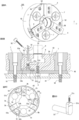
- FIG. 1 is a perspective view of a chuck of a first embodiment. It is the elements on larger scale of the chuck of embodiment 1, and Drawing 3A is an assembly drawing and Drawing 3B is an exploded view. It is a figure which shows the chuck
- FIG. 4A is a perspective view
- FIG. 4B is sectional drawing.
- 5 is a partially exploded view of a chuck of Embodiment 2.
- FIG. 6A is a partially exploded view of the chuck of Embodiment 2
- FIG. 6A shows a front body, a plunger, and a jaw
- FIG. 6B shows a back side of the front body.
- FIG. 7A is a cross-sectional view taken along the line XX and FIG. 7B is a diagram for explaining the principle.
- FIG. 8A is a perspective view
- FIG. 8B is a cross-sectional view
- FIG. 8C is a rear view of a front body
- FIG. 8D is a perspective view of an adjuster.
- FIG. 9A is a perspective view
- FIG. 9B is a Y1-Y1 sectional view
- FIG. 9C is an adjustment screw
- FIG. 9D is a Y2-Y2 sectional view.
- Embodiment 1 Referring to the cross section of the chuck 100 of FIG. 1A and the perspective view of FIG. 2, the chuck 100 includes three jaws 4 that move radially in the front (rightward in the figure) surface of the body 1.
- the body 1 is composed of a rear body 2 and a cylindrical front body 3.
- the rear body 2 is rotated about an axis C (indicated by a dashed line in the figure) of the chuck 100 as an axial center (rotation center of the chuck) by a spindle of a machine tool (disposed on the left side of the rear body 2 in FIG. 1).
- the front body 3 is pressed against the rear body 2 in the longitudinal direction of the axis C by a spring 9.
- the front body 3 is a rear body in a plane (in the figure, in the radial direction relative to the axis C or in the X and Y directions in FIG. 2) perpendicular to the Z direction (the longitudinal direction of the axis C with the right direction in the figure as the front).
- a minute gap is provided between the collar 3 c of the front body 3 and the side surface of the rear body 2 so as to be able to move slightly with respect to 2.
- a plunger 8 which moves back and forth along an axis C.
- the body 1 is provided with a master jaw 6 which is guided by a slot 3a of the front body 3 and slides in the radial direction, and the plunger 8 and the master jaw 6 are engaged so as to make a wedge action.
- the plunger 8 is pulled in by the thrust force F of the cylinder 50, the master jaw 6 slides in the radial direction by the wedge action of the plunger 8 and the master jaw 6.
- the guide bars 7 are erected in parallel in the Z direction toward the front body 3 at a plurality of locations from the rear body 2.
- the guide bar 7 includes an enlarged portion 7a having a groove into which the sliding ring 7b is inserted, a body shaft 7c, and a screw shaft 7d, and a stepped portion between the body shaft 7c and the screw shaft 7d. It is equipped with 7e.
- the front body 3 is provided with a plurality of guide holes 5.
- the guide hole 5 is composed of a receiving surface 5a for receiving the enlarged portion 7a, a through hole 5b following it, and a step 5c between the receiving surface 5a and the through hole 5b.
- a spring 9 is mounted between the enlarged portion 7a of the guide bar 7 and the stepped portion 5c.
- the spring 9 is biasing means for pressing the front body 3 against the rear body 2.
- the screw shaft portion 7d is screwed directly to the fastening hole of the spindle of the machine tool via the through hole 2b of the rear body 2 or to the back plate fixed to the spindle, and the step portion 7e
- the guide bar 7 firmly fixes the rear body 2 to the spindle. Since the front body 3 is pressed against the rear body 2 by the spring 9, the relative position between the rear body 2 and the front body 3 is maintained, but in a state where the turning load of the work on the chuck 100 is applied, the rear body 2 and the front body It is not guaranteed that the relative position with 3 is maintained.
- Adjustment screw holes 12 are bored from the circumferential surface 3 b of the front body 3 toward the respective guide holes 5, and the adjustment screw holes 12 pass through the through holes 5 b.
- An adjusting bolt 13 is screwed into the adjusting screw hole 12.
- FIG. 3 is a partially enlarged view of the chuck 100 showing details of the adjustment bolt 13.
- the adjustment bolt 13 is doubled. That is, the adjustment bolt 13 has an outer screw 13a and an outer screw 13a disposed inside the outer screw 13a.
- the outer screw 13a and the inner screw 13b are right-handed screws.
- the inner screw 13b has a slightly smaller pitch than the outer screw 13a.
- the back side surface of the adjusting screw hole 12 is a flat surface 12a, which faces the flat surface 13c provided on the side surface of the tip of the inner screw 13b, and prevents the rotation of the inner screw 13b.
- the inner screw 13b advances by the difference in pitch.
- the tip of the inner screw 13b abuts on the barrel shaft 7c of the guide bar 7 present in the through hole 5b.
- the inner screw 13b has a smaller pitch than the outer screw 13a, when the outer screw 13a is turned, the axial moving distance of the inner screw 13b is smaller than the axial moving distance of the outer screw 13a. Become. For this reason, the adjustment bolt 13 can adjust the position of the guide bar 7 minutely.
- the correction process according to the method of correcting the grasping accuracy of the chuck 100 will be described.
- the bolt 11 screwed into the fixing hole 2a is loosened. Since the guide bar 7 fastens the rear body 2 to the spindle, the position and attitude of the rear body 2 with respect to the axis C are maintained. Further, the spring 9 presses the front body 3 against the rear body 2 so that the front body 3 does not come off or tilt even when the bolt 11 is loosened.
- Three adjustment bolts 13 are disposed on the front body 3 in such a manner as to push the side surfaces of the guide bar 7 from three directions.
- the front body 3 is moved slightly in the radial direction about the axis C, and the core of the work is Also by setting the position on the axis C, it is possible to correct the grasping accuracy.
- the front body 3 translates along the end face of the rear body 2. At this time, since the front body 3 is pressed against the rear body 2 by the spring 9, it does not tilt with respect to the rear body 2. Thereafter, the bolt 11 is tightened.
- the grasping accuracy can be secured.
- the side surface of the guide bar 7 is pushed in three directions by the three adjustment bolts 13, but as shown in FIG. 1B, the collar portion 3c of the front body 3 faces the side surface of the rear body 2
- the front body 3 is oriented with respect to the axis C so that the core of the work is arranged on the axis C by pressing it with three adjustment bolts 13 'arranged at angular intervals (only one place is shown in the drawing) It may be moved in the radial direction.
- the action of moving the front body may be performed when the jaw is actually grasped the work, or when the jaw is grasped the work, the fluctuation of the work is measured, and then the fluctuation is measured after the work is removed.
- the core of the work may be disposed on the axis C based on
- the embodiment shows the chuck in which the plunger 8 and the master jaw 6 are engaged so as to perform the wedge action
- the present invention can be applied to a chuck for moving the master jaw in other manners.
- the invention is also applicable to a lever type chuck as disclosed in Japanese Patent Laid-Open No. 6-277910.
- the master jaw 6 does not directly engage with the plunger 8, but it is also possible to drive the master jaw 6 between the plunger 8 and another member, for example, a wedge-shaped force increasing mechanism. It is equally applicable.
- FIG. 4 shows a chuck 200 according to a second embodiment
- FIG. 4A is a perspective view of the chuck 200
- FIG. 4B is a cross-sectional view.
- the chuck 200 is provided with three jaws 24 that move radially in the front (rightward in the figure) surface of the body 20.
- the body 20 is composed of a rear body 22 and a cylindrical front body 23.
- the rear body 22 is rotated about an axis C of the chuck 200 by a spindle of the machine tool (disposed on the left side of the rear body 22 in FIG. 4B).
- the front body 23 can move slightly along the axis C with respect to the rear body 22.
- the plunger 28 moving on the axis C in the body 20 is inserted, and the front body 23 is provided with a master jaw 26 sliding radially in the slot 23a, and the plunger 28 and the master jaw 26 are engaged so as to function as a wedge. It is united.
- the master jaw 26 slides in the radial direction by the wedge action on the master jaw 26.
- the front body 23 receives a force for moving on the axis C.
- the jaws 24 are fixed to the master jaw 26 one by one and grasp the work.
- a damper 31 made of a plate-like member is provided between the rear body 22 and the front body 23. Details of fixing of both will be described later.
- a plurality of guide bars 17 (three in the embodiment) at equal angular intervals are fastened to the rear body 22 by bolts 16 with the damper 31 interposed therebetween.
- FIG. 5 is a perspective view of the rear body 22 and the damper 31.
- the rear body 22 has seating surfaces 22a (first seating surfaces) at equal angular intervals.
- the seat surface 22a is for attaching the damper 31, and large and small through holes 22c and 22d are bored.
- the through hole 22 d is used to fix the guide bar 17 to the seat surface 22 a.
- the fan-shaped portions between the adjacent seating surfaces 22a are retracted backward (left direction in the drawing) (hereinafter referred to as fan-shaped portions 22f), and are adjacent to each other across the fan-shaped portions 22f in a bridging manner. A space is permitted to allow the damper 31 passed to the seat 22a to be elastically deformed rearward.
- Each fan-shaped portion 22 f is provided with a groove 22 b.
- An adjusting screw 41 is installed in the groove 22b in the length direction.
- the adjustment screw 41 can be rotated from the outer peripheral side P of the rear body 22.
- a slider 42 is screwed into the adjusting screw 41, and the adjusting screw 41 is moved by being rotated.
- the position of the groove 22b is the same angular position behind the jaw 24 (centered on the axis C), and the position of the seat 22a is the same angular position behind the guide bar 17 (centered on the axis C) described later. It has become.
- the damper 31 has a ring shape.
- the through holes 31 c and 31 d are arranged at equal angular intervals in the state where the through holes 31 c and 31 d are aligned in the radial direction.
- one through hole 31a is disposed at equal angular intervals therebetween.
- the through holes 31c, 31d correspond to the through holes 22c, 22d.
- the through hole 31 a is used to fix the front body 23 to the damper 31.
- FIG. 6A is a perspective view of the front body 23, the plunger 28, the master jaw 26, and the guide bar 17.
- FIG. FIG. 6B shows the back of the front body 23.
- the plurality of guide bars 17 (three in the example) have sliding surfaces 17a on the side surfaces of the head, and are provided with grooves for receiving the ring-shaped seal 17b.
- Reference numeral 17 c denotes a body whose end abuts on the damper 31.
- the front body 23 is provided with a plurality of guide holes 23b (three in the example) at equal angular intervals, and the guide bars 17 are accommodated.
- An inner peripheral surface on the front side of the guide hole 23b is a sliding surface 23d that enables the front body 23 to slide on the axis C along the sliding surface 17a of the guide bar 17.
- the central through hole 17d of the guide bar 17 accommodates a bolt 16 for fixing the guide bar 17 directly to a spindle of a machine tool (not shown) or to a back plate fixed to the spindle.
- a minute space is required between the sliding surface 17a and the sliding surface 23d, and in this minute range, it is inclined with respect to the axis C
- the front body 23 is movable.
- the back surface of the front body 23 is provided with three seating surfaces 23c (second seating surfaces) at equal angular intervals.
- the seat surfaces 23c are provided behind the master jaw 26 and at three locations similar to the number of the seat surfaces 22a of the rear body 22 (three are also the number of the master jaws 26).
- the seating surface 23c protrudes to the rear side (the front side in the drawing of FIG. 6B) compared to the other portion 23f on the same circumference. This is to secure a space for permitting deformation of the flat damper 31 at a place other than the seating surface 23c.
- the seat 23c is provided with a hole 23e to which a bolt 36 (second bolt) is fastened via the through hole 31a of the damper 31.
- the damper 31 has the bolt 36 inserted in the through hole 31a and is fastened to the seating surface 23c of the front body 23 by the bolt 36. .
- the head of the bolt 36 is accommodated in a clearance hole 22 e provided in the rear body 22 with a margin.
- the damper 31 has a bolt 29 inserted in the through hole 31 d or a bolt 16 inserted in the through hole 31 c at positions of the through holes 31 c and 31 d adjacent to both sides of the through hole 31 a, not shown.
- the bearing surface 22a of the spindle or rear body 22 of the machine tool is fastened by a bolt 29 or a bolt 16 (first bolt).
- the guide bar 17 is fastened to the bearing surface 22a by a bolt 16 (second bolt).
- the dampers 31 have a ring shape (see FIG. 5), the rear body 22, the front body 23, the rear body 22, and the front body 23 are alternately fixed in order in the circumferential direction. .
- the dampers 31 are arranged in a bridge-like manner between the bearing surfaces 22a provided at intervals, and the dampers 31 are fastened by the bolts 16 to the respective bearing surfaces 22a.
- the damper 31 is fastened to the seating surface 23c of the front body 23 by bolts 36 between the seating surfaces 22a adjacent to each other.
- the positions at which the dampers 31 are bridged by the adjacent seating surfaces 22a are three in the embodiment but may be three or more.
- the fixed state is described with reference to FIG. 4B.
- the rear body 22 is fastened to the spindle or the back plate by bolts 16 (with the guide bar 17 interposed therebetween).
- the damper 31 is sandwiched between the rear body 22 and the guide bar 17 and fastened by a bolt 29.
- the front body 23 is fastened to the damper 31 by a bolt 36.
- the front body 23 is indirectly fixed to the spindle. Since the damper 31 is in a state of being fastened by the bolts 16, 29, 36, there is no rattling in the radial direction centering on the axis C, and a slight inclination with respect to the axis C as described later And allows swinging of the front body 23 relative to the rear body 22 only.
- the damper 31 Since the damper 31 is thin, its rigidity is low in the direction parallel to the axis C and it is easily bent. However, the thinness of the damper 31 hardly affects the deformation (displacement) in the radial direction about the axis C. That is, the rigidity of the damper 31 in the radial direction about the axis C is higher than the rigidity of the damper 31 in the direction parallel to the axis C. Therefore, the damper 31 is easily deformed (displaced) in the direction parallel to the axis C, but the damper 31 is not easily deformed (displaced) in the radial direction about the axis C.
- FIG. 7 is a view for explaining a structure for correcting the grasping accuracy by the chuck 200.
- FIG. 7A shows an XX cross section in FIG. 4A.
- the XX cross section is a view taken along the groove 22 b and viewed from the outer peripheral side of the rear body 22.
- the damper 31 supports the load from one bearing surface 23c between the adjacent bearing surfaces 22a.
- the adjustment screw 41 can be rotated from the outer peripheral surface of the rear body 22. By rotating the adjusting screw 41, the position of the slider 42 is changed.
- the spring constant of the damper 31 can be arbitrarily changed.
- the back side of the slider 42 is in contact with the rear body 22 to transfer the compression force from the damper 31 to the rear body 22.
- FIG. 7B to 7D schematically show the displacement of the state of the damper 31 at the positions of the three seating surfaces 23c.
- FIG. 7B shows a state in which the slider 42 is in the center (fixed position of the seating surface 23c), and FIGS. 7C and 7D are in a state away from the center.
- the damper 31 deforms into the space of the fan-shaped portion 22f. Since the rear body 22 backs up the rear surface of the slider 42, the length of deformation of the damper 31 is short in FIG. 7B and is long in FIGS. 7C and 7D. Therefore, the spring constant of the damper 31 can be changed at the fixed position of the seating surface 23c.
- the front body 23 may be slightly inclined in the direction of 360 degrees around the axis C as shown by the arrow Q in FIG. it can.
- the front body 23 is slightly inclined by making the amount of deformation of the damper 31 different by the adjusting screw 41 and the slider 42 so that the core of the work is directed to the center. This makes it possible to adjust the work core.
- the adjustment screw 41 can be used to make extremely fine adjustment so that the core of the workpiece when the workpiece is actually grasped on the workpiece gripping surface of the jaw 24 is aligned with the axis C.
- the positions of the sliders 42 are set at equal angular intervals, but if the positional relationship is such that the axis C is included in the figure enclosed by the straight line connecting at least three sliders 42 good.
- the front body 23 is inclined with respect to the axis C to form the jaw 24 so that the core of the work is held on the axis C when the jaw 24 holds the work. There is no need to add it, and the grasping accuracy can be secured.
- the act of tilting the front body may be performed while actually holding the work on the jaw, or may be performed after measuring the movement of the work while holding the work on the jaw and then removing the work.
- Embodiment 3 The chuck 300 of the third embodiment is shown in FIG.
- the same components as in the first and second embodiments are given the same reference numerals.
- the position of the slider 42 is changed to change the spring constant of the damper 31.
- the position of the slider 51b is changed to change the spring constant of the damper 45.
- FIG. 8A a plurality of (three in the embodiment) maintenance holes 56 provided at equal angular intervals on the front side of the front body 43 are provided.
- the sealing bolt 52 is normally screwed into the female screw hole 51d of the adjuster 51, and is in a sealed state.
- FIG. 8B when the sealing bolt 52 is taken out from the maintenance hole 56, the operation end 51a of the adjuster 51 appears.
- the sealing bolt 52 prevents penetration of cutting powder.
- the operation end 51 a is a female groove for receiving the hexagonal wrench 55, and can rotate the adjuster 51 existing between the front body 43 and the damper 45.
- the female screw hole 51d is provided on the back side of the operation end 51a.
- the adjuster 51 penetrates the front body 43 and faces the damper 45.
- the adjuster 51 has a slider 51b on the side directly facing the damper 45, and the slider 51b contacts the damper 45 in the process of deformation of the damper 45.
- a recess 53a for swinging the slider 51b is provided on the front body 43 side.
- latching notches 53b are provided at equal angular intervals on the recess 53a side, and the adjuster 51 has claws 51c elastically advancing and retracting with respect to the latching notch 53b. Is provided. Then, after adjusting the rotation angle of the adjuster 51 using the hexagonal wrench 55, the adjuster 51 can be fixed by tightening the sealing bolt 52. Further, in the above-described embodiment, the adjuster 51 is fixed by tightening the sealing bolt 52.
- the side surface of the adjuster 51 from the side surface of the front body 43 It is also possible to provide a female screw hole leading to the above and fix it by screwing a bolt into the female screw hole.
- the spring constant of the damper 45 can be changed by changing the position of the slider 51b from the front side of the front body 43 which is often exposed in most machine tools. . Further, as compared with the case where the adjustment screw 41 and the slide 42 are provided on the rear body 22 as in the second embodiment, the number of parts can be reduced, and the cost can be reduced.
- Embodiment 4 The chuck 400 of the fourth embodiment is shown in FIG.
- the fourth embodiment is a modification of the first embodiment.
- the axis C is centered by pressing the side surface of the rear body 2 or the side surface of the guide bar 7 inserted in each guide hole of the front body 3 from the side surface of the front body 3 by a plurality of adjustment bolts 13.
- the front body 3 is moved in the radial direction, but in the fourth embodiment, the adjustment screw 61 is operated from the front side of the front body 63 to move the front body 63 in the radial direction about the axis C.
- the same components as those in the first embodiment are given the same reference numerals.
- a plurality of (three in the embodiment) adjustment screws 61 are provided at equal angular intervals with respect to the chuck 400, and the operation end 61 a is exposed on the front side of the front body 63.
- the operation end 61 a is a female groove for receiving a hexagonal wrench, and can rotate the adjusting screw 61.
- the adjusting screw 61 has a screw in the shaft portion 61 b, and can advance and retract in the front body 63 in the direction of the axis C.
- the head portion 61 c of the adjusting screw 61 is tapered, and slides on an inclined sliding surface 62 a provided on the rear body 62 side. The head 61 c advances and retracts in the direction of the axis C, thereby sliding the sliding surface 62 a and moving the front body 63 in the radial direction about the axis C.
Abstract
The present invention addresses the problem of performing correction so that an axis line of a chuck and a core of a workpiece are highly accurately aligned with each other. Provided is a chuck correction method that is provided with a correction step. The chuck is provided with a body, a plunger, and a jaw. The body has a rear body and a front body that is disposed on the front side of the rear body, the plunger is provided in the body, and is configured so as to move on an axis line of the body, and the jaw is configured so as to move, due to the movement of the plunger, in the diameter direction with the axis line at the center by being guided by the front body. In the correction step, when a workpiece is held by the jaw, the front body is moved in the diameter direction with the axis line at the center, while maintaining the position of the rear body with respect to the axis line, or the front body is tilted with respect to the axis line, while maintaining the position of the rear body with respect to the axis line.
Description
本発明は、工作機械に使用するチャックの補正方法に関するものである。
The present invention relates to a method of correcting a chuck used in a machine tool.
ワークを高精度に把握するために、ジョウの機上成形が行われている。機上成形は成形プラグを把握した状態でジョウの把握面を加工して、チャックの回転中心とワーク中心とを高精度に一致させるのが一般的である。しかし、通常、ジョウのワーク把握面よりもチャックボディ側で成形プラグを把握した状態でジョウの把握面が加工されるため、把握面の位置と成形プラグを把握する位置は異なっている。このため、実際にワークを把握したときに、ワーク中心がチャックの回転中心から微妙にズレることがある。
In order to grasp the work with high accuracy, on-machine molding of jaws is performed. In the on-the-machine forming, generally, the gripping surface of the jaw is processed while grasping the forming plug so that the center of rotation of the chuck and the center of the work coincide with high accuracy. However, since the grasping surface of the jaw is processed while grasping the forming plug on the chuck body side more than the workpiece grasping surface of the jaw, the position of the grasping surface and the position for grasping the forming plug are different. Therefore, when the workpiece is actually grasped, the workpiece center may be slightly shifted from the rotation center of the chuck.
特許文献1においては、ジョウを取り付けるドローバーに成形プラグを把握させ、ドローバーの先端を成形する例が示されている。この例によれば、ドローバーに成形プラグ把握部を設けると、ジョウがチャックボディからチャックの軸線前方に離れてしまう。ジョウがチャックボディからチャックの軸線前方に離れてしまうと、ワークの中心(芯)がチャックの回転中心(軸線)からズレやすくなる。本発明は、ワークの中心(芯)とチャックの回転中心(軸線)とを一致させる精度を向上させることを目的としている。
Patent Document 1 shows an example in which a drawbar for attaching a jaw is grasped by a forming plug, and the tip of the drawbar is formed. According to this example, when the forming plug grasping portion is provided on the draw bar, the jaws are separated from the chuck body in front of the axis of the chuck. When the jaws are separated from the chuck body in front of the axis of the chuck, the center (core) of the work is easily displaced from the rotation center (axis) of the chuck. An object of the present invention is to improve the accuracy of matching the center (core) of a work with the rotation center (axis) of a chuck.
本発明によれば、補正工程を備える、チャックの補正方法であって、前記チャックは、ボディと、プランジャと、ジョウとを備え、前記ボディは、リアボディと該リアボディの前方側に配置されたフロントボディとを有し前記プランジャは、該ボディ内に設けられ、前記ボディの軸線上を移動するように構成され、前記ジョウは、前記プランジャの移動によって前記フロントボディにガイドされて前記軸線を中心とした径方向へ移動するように構成され、前記補正工程では、前記ジョウにワークを把握させたときにおいて、前記軸線に対する前記リアボディの位置を維持しながら前記軸線を中心とした径方向に前記フロントボディを移動させる、又は、前記軸線に対する前記リアボディの位置を維持しながら前記フロントボディを前記軸線に対して傾けさせる、方法が提供される。
According to the present invention, there is provided a chuck correction method comprising a correction step, wherein the chuck comprises a body, a plunger, and a jaw, the body being a rear body and a front disposed on the front side of the rear body. The plunger is provided in the body and configured to move on an axis of the body, and the jaw is guided by the movement of the plunger to the front body to center the axis. The front body is configured to move in the radial direction, and in the correction step, when the jaw is made to grasp the workpiece, the front body in the radial direction centering on the axis while maintaining the position of the rear body with respect to the axis. Or move the front body to the axis while maintaining the position of the rear body with respect to the axis. Let tilted against, a method is provided.
本発明によれば、軸線に対するリアボディの位置を維持しながら、軸線を中心とした径方向にフロントボディを移動させる、又は、軸線に対するリアボディの位置を維持しながら、フロントボディを軸線に対して傾けさせるので、ジョウに対して成形を加えなくても、ワークの中心(芯)とチャックの回転中心(軸線)とを一致させる精度を向上させることができる。
According to the present invention, while maintaining the position of the rear body with respect to the axis, moving the front body in the radial direction about the axis or tilting the front body with respect to the axis while maintaining the position of the rear body with respect to the axis Thus, the accuracy in matching the center (core) of the work with the rotation center (axis) of the chuck can be improved without forming the jaws.
好ましくは、前記チャックは、前記リアボディから前記フロントボディに向けて設けられたガイドバーを有し、前記ガイドバーは、前記フロントボディに設けられたガイド孔に挿入される。
好ましくは、前記チャックは、前記フロントボディを前記リアボディに固定するボルトを有し、前記ボルトを緩めた状態で前記フロントボディを前記径方向に移動させ、移動が終わった段階で前記ボルトを締結する。
好ましくは、前記フロントボディを前記リアボディに押しつけておく付勢手段を前記ガイドバーに装着する。
好ましくは、調整ボルトを前記フロントボディに挿入することによって、前記調整ボルトを前記リアボディの側面若しくは前記ガイドバーの側面に押し付け、前記フロントボディを前記径方向に移動させる。
好ましくは、前記リアボディに傾斜状の摺動面が設けられ、前記フロントボディの前面側からの回転操作により前記フロントボディの中を進退可能であって、テーパー状の頭部が前記摺動面を摺動する調整螺子を有し、前記調整螺子を進退させることで、テーパー状の頭部が前記摺動面を摺動し、前記フロントボディを前記径方向に移動させる。
好ましくは、前記リアボディは、間隔を開けて設けられた第1の座面の間をダンパーが橋渡し状に配置され、其々の座面に対して第1のボルトにより前記ダンパーが締結されており、前記フロントボディは、その背面に設けられた第2の座面に対して、前記第1の座面の間で第2のボルトにより前記ダンパーが締結されて、かつ隣り合う前記第1の座面の間を橋渡し状に配置された前記ダンパーに対して、前記ダンパーの変形長を変更する摺動子が設けられており、前記補正工程では、前記ジョウにワークを把握させたときにおいて、前記摺動子の位置を変更して前記フロントボディを前記軸線に対して傾ける。
好ましくは、前記ダンパーが橋渡し状に配置される位置を、等角度間隔に少なくとも3箇所以上配置する。 Preferably, the chuck has a guide bar provided from the rear body toward the front body, and the guide bar is inserted into a guide hole provided in the front body.
Preferably, the chuck has a bolt for fixing the front body to the rear body, moves the front body in the radial direction with the bolt loosened, and fastens the bolt when the movement is finished. .
Preferably, biasing means for pressing the front body against the rear body is attached to the guide bar.
Preferably, by inserting an adjusting bolt into the front body, the adjusting bolt is pressed against the side surface of the rear body or the side surface of the guide bar to move the front body in the radial direction.
Preferably, the rear body is provided with an inclined sliding surface, and the inside of the front body can be advanced and retracted by a rotation operation from the front side of the front body, and the tapered head is the sliding surface. It has an adjusting screw that slides, and by moving the adjusting screw back and forth, the tapered head slides on the sliding surface to move the front body in the radial direction.
Preferably, in the rear body, dampers are arranged like a bridge between the first seating surfaces provided at intervals, and the dampers are fastened to the respective seating surfaces by first bolts. The front body has a second seating surface provided on the rear surface, and the damper is fastened between the first seating surfaces by a second bolt, and the adjacent first seatings A slider is provided for changing the deformation length of the damper to the damper arranged in a bridge shape between the surfaces, and in the correction step, when the jaw is made to grasp the work, The position of the slider is changed to tilt the front body relative to the axis.
Preferably, at least three or more positions at which the dampers are arranged in a bridge shape are arranged at equal angular intervals.
実施形態1.
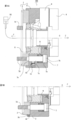
図1Aのチャック100の断面および、図2の斜視図を参照し、チャック100は、ボディ1の前方(図中右方向)の面に径方向に移動する3つのジョウ4を備えている。ボディ1は、リアボディ2と円筒状のフロントボディ3とからなっている。リアボディ2は、工作機械のスピンドル(図1において、リアボディ2の左側に配置される)により、チャック100の軸線C(図中一点破線で示す)を軸心(チャックの回転中心)として回転する。フロントボディ3はリアボディ2に対して軸線Cの長さ方向にバネ9により押しつけられている。一方、Z方向(図中右方向を前方とする軸線Cの長さ方向)に垂直な平面(図中、軸線Cに対する径方向、若しくは図2のX、Y方向)において、フロントボディ3はリアボディ2に対して微少移動可能なように、フロントボディ3のカラー部3cとリアボディ2の側面の間には、微少隙間が設けられている。ボディ1内には、軸線C上に前後移動するプランジャ8が挿入されている。また、ボディ1にはフロントボディ3のスロット3aにガイドされて径方向へ摺動するマスタジョウ6が設けられ、プランジャ8とマスタジョウ6が楔作用をなすべく係合されている。シリンダ50の推力Fによりプランジャ8が引き込まれると、プランジャ8及びマスタジョウ6の楔作用により、マスタジョウ6が径方向へ摺動する。 Embodiment 1
Referring to the cross section of thechuck 100 of FIG. 1A and the perspective view of FIG. 2, the chuck 100 includes three jaws 4 that move radially in the front (rightward in the figure) surface of the body 1. The body 1 is composed of a rear body 2 and a cylindrical front body 3. The rear body 2 is rotated about an axis C (indicated by a dashed line in the figure) of the chuck 100 as an axial center (rotation center of the chuck) by a spindle of a machine tool (disposed on the left side of the rear body 2 in FIG. 1). The front body 3 is pressed against the rear body 2 in the longitudinal direction of the axis C by a spring 9. On the other hand, the front body 3 is a rear body in a plane (in the figure, in the radial direction relative to the axis C or in the X and Y directions in FIG. 2) perpendicular to the Z direction (the longitudinal direction of the axis C with the right direction in the figure as the front). A minute gap is provided between the collar 3 c of the front body 3 and the side surface of the rear body 2 so as to be able to move slightly with respect to 2. In the body 1 is inserted a plunger 8 which moves back and forth along an axis C. Further, the body 1 is provided with a master jaw 6 which is guided by a slot 3a of the front body 3 and slides in the radial direction, and the plunger 8 and the master jaw 6 are engaged so as to make a wedge action. When the plunger 8 is pulled in by the thrust force F of the cylinder 50, the master jaw 6 slides in the radial direction by the wedge action of the plunger 8 and the master jaw 6.
図1Aのチャック100の断面および、図2の斜視図を参照し、チャック100は、ボディ1の前方(図中右方向)の面に径方向に移動する3つのジョウ4を備えている。ボディ1は、リアボディ2と円筒状のフロントボディ3とからなっている。リアボディ2は、工作機械のスピンドル(図1において、リアボディ2の左側に配置される)により、チャック100の軸線C(図中一点破線で示す)を軸心(チャックの回転中心)として回転する。フロントボディ3はリアボディ2に対して軸線Cの長さ方向にバネ9により押しつけられている。一方、Z方向(図中右方向を前方とする軸線Cの長さ方向)に垂直な平面(図中、軸線Cに対する径方向、若しくは図2のX、Y方向)において、フロントボディ3はリアボディ2に対して微少移動可能なように、フロントボディ3のカラー部3cとリアボディ2の側面の間には、微少隙間が設けられている。ボディ1内には、軸線C上に前後移動するプランジャ8が挿入されている。また、ボディ1にはフロントボディ3のスロット3aにガイドされて径方向へ摺動するマスタジョウ6が設けられ、プランジャ8とマスタジョウ6が楔作用をなすべく係合されている。シリンダ50の推力Fによりプランジャ8が引き込まれると、プランジャ8及びマスタジョウ6の楔作用により、マスタジョウ6が径方向へ摺動する。 Embodiment 1
Referring to the cross section of the
ガイドバー7はリアボディ2から複数箇所で、フロントボディ3に向けてZ方向に平行に立設されている。ガイドバー7は、摺動リング7bが挿入される溝を有する拡大部7a、胴軸部7c、螺子軸部7dとからなり、胴軸部7cと螺子軸部7dとの間には、段差部7eを備えている。フロントボディ3には、複数のガイド孔5が設けられている。ガイド孔5は、拡大部7aを受ける受面部5aと、これに続く通し孔部5bと、受面部5aと通し孔部5bとの間の段差部5cからなっている。ガイドバー7の拡大部7aと段差部5cとの間にバネ9が装着されている。バネ9は、フロントボディ3をリアボディ2に押しつけておく付勢手段である。螺子軸部7dは、リアボディ2の通し孔2bを介して、工作機械のスピンドルの締結孔に対して直接的にあるいは、スピンドルに固定されたバックプレートに対して螺合されており、段差部7eにより、ガイドバー7はリアボディ2をスピンドルにしっかり固定している。フロントボディ3はバネ9によりリアボディ2に押しつけられているので、リアボディ2とフロントボディ3との相対位置は維持されるが、チャック100に対するワークの旋削負荷が加わった状態において、リアボディ2とフロントボディ3との相対位置が維持されることが保障されるわけではない。また、複数のボルト11が、フロントボディ3の通し孔15を介してリアボディ2の固定孔2aに螺合されることにより、フロントボディ3をリアボディ2に対して複数箇所にて締結状態にしている。フロントボディ3の周面部3bから、各ガイド孔5に向かって調整螺子孔12が穿孔されており、調整螺子孔12は通し孔部5bに貫通している。調整螺子孔12には、調整ボルト13が螺合されている。
The guide bars 7 are erected in parallel in the Z direction toward the front body 3 at a plurality of locations from the rear body 2. The guide bar 7 includes an enlarged portion 7a having a groove into which the sliding ring 7b is inserted, a body shaft 7c, and a screw shaft 7d, and a stepped portion between the body shaft 7c and the screw shaft 7d. It is equipped with 7e. The front body 3 is provided with a plurality of guide holes 5. The guide hole 5 is composed of a receiving surface 5a for receiving the enlarged portion 7a, a through hole 5b following it, and a step 5c between the receiving surface 5a and the through hole 5b. A spring 9 is mounted between the enlarged portion 7a of the guide bar 7 and the stepped portion 5c. The spring 9 is biasing means for pressing the front body 3 against the rear body 2. The screw shaft portion 7d is screwed directly to the fastening hole of the spindle of the machine tool via the through hole 2b of the rear body 2 or to the back plate fixed to the spindle, and the step portion 7e Thus, the guide bar 7 firmly fixes the rear body 2 to the spindle. Since the front body 3 is pressed against the rear body 2 by the spring 9, the relative position between the rear body 2 and the front body 3 is maintained, but in a state where the turning load of the work on the chuck 100 is applied, the rear body 2 and the front body It is not guaranteed that the relative position with 3 is maintained. Further, the plurality of bolts 11 are screwed into the fixing holes 2 a of the rear body 2 through the through holes 15 of the front body 3, thereby fastening the front body 3 to the rear body 2 at a plurality of places. . Adjustment screw holes 12 are bored from the circumferential surface 3 b of the front body 3 toward the respective guide holes 5, and the adjustment screw holes 12 pass through the through holes 5 b. An adjusting bolt 13 is screwed into the adjusting screw hole 12.
図3は、調整ボルト13の詳細を示すチャック100の部分拡大図である。調整ボルト13は二重になっていている。つまり、調整ボルト13は、外側ネジ13aと、外側ネジ13aの内側に配置される外側ネジ13aとを有する。外側ネジ13a及び内側ネジ13bは右ネジである。また、内側ネジ13bは外側ネジ13aよりピッチが少し小さい。調整螺子孔12の奥側の側面は平面12aになっており、内側ネジ13bの先部側面に設けられた平面13cと対向し、内側ネジ13bの回転を阻止する。外側ネジ13aを1回転時計回りに回すと内側ネジ13bはピッチの差だけ進む。内側ネジ13bの先端は、通し孔部5b内に存在するガイドバー7の胴軸部7cに当接する。このように、内側ネジ13bは外側ネジ13aよりピッチが小さいので、外側ネジ13aが回されたときにおいて、内側ネジ13bの軸方向の移動距離は、外側ネジ13aの軸方向の移動距離よりも小さくなる。このため、調整ボルト13はガイドバー7の位置を微小に調整することができる。
FIG. 3 is a partially enlarged view of the chuck 100 showing details of the adjustment bolt 13. The adjustment bolt 13 is doubled. That is, the adjustment bolt 13 has an outer screw 13a and an outer screw 13a disposed inside the outer screw 13a. The outer screw 13a and the inner screw 13b are right-handed screws. In addition, the inner screw 13b has a slightly smaller pitch than the outer screw 13a. The back side surface of the adjusting screw hole 12 is a flat surface 12a, which faces the flat surface 13c provided on the side surface of the tip of the inner screw 13b, and prevents the rotation of the inner screw 13b. When the outer screw 13a is turned clockwise one turn, the inner screw 13b advances by the difference in pitch. The tip of the inner screw 13b abuts on the barrel shaft 7c of the guide bar 7 present in the through hole 5b. Thus, since the inner screw 13b has a smaller pitch than the outer screw 13a, when the outer screw 13a is turned, the axial moving distance of the inner screw 13b is smaller than the axial moving distance of the outer screw 13a. Become. For this reason, the adjustment bolt 13 can adjust the position of the guide bar 7 minutely.
次に、チャック100の把握精度の補正方法に係る補正工程を説明する。まず、固定孔2aに螺合されたボルト11を緩める。ガイドバー7がリアボディ2をスピンドルに締結しているので、軸線Cに対するリアボディ2の位置や姿勢は維持されている。また、ボルト11を緩めた状態でもフロントボディ3が抜けたり傾いたりしないように、バネ9はフロントボディ3をリアボディ2に押付けている。3個の調整ボルト13はガイドバー7の側面を三方から押す形でフロントボディ3に配置されている。
Next, the correction process according to the method of correcting the grasping accuracy of the chuck 100 will be described. First, the bolt 11 screwed into the fixing hole 2a is loosened. Since the guide bar 7 fastens the rear body 2 to the spindle, the position and attitude of the rear body 2 with respect to the axis C are maintained. Further, the spring 9 presses the front body 3 against the rear body 2 so that the front body 3 does not come off or tilt even when the bolt 11 is loosened. Three adjustment bolts 13 are disposed on the front body 3 in such a manner as to push the side surfaces of the guide bar 7 from three directions.
まず、ジョウ4にワークを把握させ、前記ワークの芯が軸線C上の位置になるように、3個の調整ボルト13を互いに押し引きし、軸線Cを中心とした径方向(Z方向に対して垂直な平面内)にフロントボディ3を微少に移動させる。この状態で、ボルト11を締付けるとフロントボディ3はリアボディ2に正確な把握精度となる位置で固定され、チャック100の把握精度の補正ができる。また、調整ボルト13を全て緩めた状態でフロントボディ3の周面部3bを無反動ハンマーでたたくことにより、軸線Cを中心とした径方向においてフロントボディ3を微少に移動させて、ワークの芯を軸線C上の位置になるようにすることでも把握精度の補正ができる。フロントボディ3はリアボディ2の端面に沿って平行移動する。この際、フロントボディ3は、バネ9によりリアボディ2に押付けられているため、リアボディ2に対して傾かない。その後、ボルト11を締付ける。本実施形態によれば、ワークの芯が軸線C上に配置されるように、軸線Cを中心とした径方向にフロントボディ3を移動させることで、把握精度を確保することができる。上記実施形態においては、3個の調整ボルト13によりガイドバー7の側面を三方から押す形としていたが、図1Bに示すように、フロントボディ3のカラー部3cからリアボディ2の側面に対して等角度間隔に配置された3個の調整ボルト13 ' により押しつけて(図面では、1箇所のみ示した)、ワークの芯が軸線C上に配置されるように、フロントボディ3を軸線Cに対して径方向に移動させても良い。なお、フロントボディを移動させる行為は、ジョウにワークを実際に把握させた時に行っても良いし、ジョウにワークを把握させた時にワークの振れを測定し、その後ワークを取り外してから測定した振れに基づきワークの芯が軸線C上に配置されるようにしても良い。また、実施形態では、プランジャ8とマスタジョウ6が楔作用をなすべく係合されているチャックを示したが、他の態様でマスタジョウを移動させるチャックにも適用できる。例えば、特開平6-277910号に示されるようなレバー式チャックに対しても適用可能である。また、マスタジョウ6が直接的にプランジャ8と係合せず、プランジャ8との間に他の部材、例えば、楔形状の増力機構などを介してマスタジョウ6を駆動させるタイプのチャックに対しても同様に適用可能である。
First, make the jaw 4 grasp the work, push and pull the three adjustment bolts 13 each other so that the core of the work is on the axis C, and the radial direction centering on the axis C (with respect to the Z direction The front body 3 is moved slightly in a vertical plane). In this state, when the bolt 11 is tightened, the front body 3 is fixed to the rear body 2 at a position where accurate grasping accuracy is achieved, and the grasping accuracy of the chuck 100 can be corrected. In addition, by tapping the peripheral surface 3b of the front body 3 with a reactionless hammer while all the adjustment bolts 13 are loosened, the front body 3 is moved slightly in the radial direction about the axis C, and the core of the work is Also by setting the position on the axis C, it is possible to correct the grasping accuracy. The front body 3 translates along the end face of the rear body 2. At this time, since the front body 3 is pressed against the rear body 2 by the spring 9, it does not tilt with respect to the rear body 2. Thereafter, the bolt 11 is tightened. According to the present embodiment, by moving the front body 3 in the radial direction around the axis C such that the core of the work is disposed on the axis C, the grasping accuracy can be secured. In the above embodiment, the side surface of the guide bar 7 is pushed in three directions by the three adjustment bolts 13, but as shown in FIG. 1B, the collar portion 3c of the front body 3 faces the side surface of the rear body 2 The front body 3 is oriented with respect to the axis C so that the core of the work is arranged on the axis C by pressing it with three adjustment bolts 13 'arranged at angular intervals (only one place is shown in the drawing) It may be moved in the radial direction. In addition, the action of moving the front body may be performed when the jaw is actually grasped the work, or when the jaw is grasped the work, the fluctuation of the work is measured, and then the fluctuation is measured after the work is removed. The core of the work may be disposed on the axis C based on Further, although the embodiment shows the chuck in which the plunger 8 and the master jaw 6 are engaged so as to perform the wedge action, the present invention can be applied to a chuck for moving the master jaw in other manners. For example, the invention is also applicable to a lever type chuck as disclosed in Japanese Patent Laid-Open No. 6-277910. In addition, the master jaw 6 does not directly engage with the plunger 8, but it is also possible to drive the master jaw 6 between the plunger 8 and another member, for example, a wedge-shaped force increasing mechanism. It is equally applicable.
実施形態2.
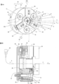
図4は、実施形態2によるチャック200を示しており、図4Aはチャック200の斜視図および、図4Bは断面図である。チャック200は、ボディ20の前方(図中右方向)の面に径方向に移動する3つのジョウ24を備えている。ボディ20は、リアボディ22と円筒状のフロントボディ23とからなっている。リアボディ22は、工作機械のスピンドル(図4Bにおいて、リアボディ22の左側に配置される)により、チャック200の軸線Cを軸心として回転する。フロントボディ23はリアボディ22に対して軸線C上で微少移動可能である。ボディ20内で軸線C上に移動するプランジャ28が挿入され、フロントボディ23にはスロット23aを径方向へ摺動するマスタジョウ26が設けられ、プランジャ28とマスタジョウ26が楔作用をなすべく係合されている。シリンダ50の推力Fにより、プランジャ28が引き込まれると、マスタジョウ26への楔作用により、マスタジョウ26が径方向へ摺動する。この際、フロントボディ23は、軸線C上を移動させる力を受ける。ジョウ24は、マスタジョウ26に1対1に固定されワークを把握する。Embodiment 2
FIG. 4 shows achuck 200 according to a second embodiment, FIG. 4A is a perspective view of the chuck 200, and FIG. 4B is a cross-sectional view. The chuck 200 is provided with three jaws 24 that move radially in the front (rightward in the figure) surface of the body 20. The body 20 is composed of a rear body 22 and a cylindrical front body 23. The rear body 22 is rotated about an axis C of the chuck 200 by a spindle of the machine tool (disposed on the left side of the rear body 22 in FIG. 4B). The front body 23 can move slightly along the axis C with respect to the rear body 22. The plunger 28 moving on the axis C in the body 20 is inserted, and the front body 23 is provided with a master jaw 26 sliding radially in the slot 23a, and the plunger 28 and the master jaw 26 are engaged so as to function as a wedge. It is united. When the plunger 28 is pulled in by the thrust force F of the cylinder 50, the master jaw 26 slides in the radial direction by the wedge action on the master jaw 26. At this time, the front body 23 receives a force for moving on the axis C. The jaws 24 are fixed to the master jaw 26 one by one and grasp the work.
図4は、実施形態2によるチャック200を示しており、図4Aはチャック200の斜視図および、図4Bは断面図である。チャック200は、ボディ20の前方(図中右方向)の面に径方向に移動する3つのジョウ24を備えている。ボディ20は、リアボディ22と円筒状のフロントボディ23とからなっている。リアボディ22は、工作機械のスピンドル(図4Bにおいて、リアボディ22の左側に配置される)により、チャック200の軸線Cを軸心として回転する。フロントボディ23はリアボディ22に対して軸線C上で微少移動可能である。ボディ20内で軸線C上に移動するプランジャ28が挿入され、フロントボディ23にはスロット23aを径方向へ摺動するマスタジョウ26が設けられ、プランジャ28とマスタジョウ26が楔作用をなすべく係合されている。シリンダ50の推力Fにより、プランジャ28が引き込まれると、マスタジョウ26への楔作用により、マスタジョウ26が径方向へ摺動する。この際、フロントボディ23は、軸線C上を移動させる力を受ける。ジョウ24は、マスタジョウ26に1対1に固定されワークを把握する。
FIG. 4 shows a
リアボディ22とフロントボディ23の間には板状部材によるダンパー31が設けられている。両者の固定についての詳細は、後述する。ダンパー31を挟んで、等角度間隔の複数のガイドバー17(実施形態では3つ)がボルト16によりリアボディ22に締結されている。
A damper 31 made of a plate-like member is provided between the rear body 22 and the front body 23. Details of fixing of both will be described later. A plurality of guide bars 17 (three in the embodiment) at equal angular intervals are fastened to the rear body 22 by bolts 16 with the damper 31 interposed therebetween.
図5は、リアボディ22とダンパー31の斜視図である。リアボディ22は、等角度間隔を開けて座面22a(第1の座面)を有している。座面22aは、ダンパー31を取り付けるもので、大小の貫通孔22c、22dが穿孔されている。貫通孔22dは、座面22aにガイドバー17を固定するために用いられる。隣り合う座面22aの間の扇状の部分は、後方(図中左方向)に向かって後退しており(以下、扇状部分22fと称す)、扇状部分22fの上を橋渡し状に跨いで隣り合う座面22aに渡されたダンパー31が後方に向けて弾性変形することを許容する空間を確保している。各扇状部分22fには、溝22bが設けられている。溝22bには、その長さ方向に、調整螺子41が設置されている。調整螺子41は、リアボディ22の外周側Pから、回転させることが可能である。調整螺子41には摺動子42が螺合されており、調整螺子41を回転されることにより移動する。溝22bの位置はジョウ24の後方の同一角度位置(軸線Cを中心とした)であり、座面22aの位置は後述のガイドバー17の後方の同一角度位置(軸線Cを中心とした)となっている。
FIG. 5 is a perspective view of the rear body 22 and the damper 31. As shown in FIG. The rear body 22 has seating surfaces 22a (first seating surfaces) at equal angular intervals. The seat surface 22a is for attaching the damper 31, and large and small through holes 22c and 22d are bored. The through hole 22 d is used to fix the guide bar 17 to the seat surface 22 a. The fan-shaped portions between the adjacent seating surfaces 22a are retracted backward (left direction in the drawing) (hereinafter referred to as fan-shaped portions 22f), and are adjacent to each other across the fan-shaped portions 22f in a bridging manner. A space is permitted to allow the damper 31 passed to the seat 22a to be elastically deformed rearward. Each fan-shaped portion 22 f is provided with a groove 22 b. An adjusting screw 41 is installed in the groove 22b in the length direction. The adjustment screw 41 can be rotated from the outer peripheral side P of the rear body 22. A slider 42 is screwed into the adjusting screw 41, and the adjusting screw 41 is moved by being rotated. The position of the groove 22b is the same angular position behind the jaw 24 (centered on the axis C), and the position of the seat 22a is the same angular position behind the guide bar 17 (centered on the axis C) described later. It has become.
ダンパー31は、リング形状を有している。大小1つずつ貫通孔31c、31dが径方向に並んだ状態で、等角度間隔に配置されている。また、その間に1つの貫通孔31aが等角度間隔に配置されている。貫通孔31c、31dは、貫通孔22c、22dに対応するものである。貫通孔31aは、フロントボディ23をダンパー31に固定するために使用される。
The damper 31 has a ring shape. The through holes 31 c and 31 d are arranged at equal angular intervals in the state where the through holes 31 c and 31 d are aligned in the radial direction. In addition, one through hole 31a is disposed at equal angular intervals therebetween. The through holes 31c, 31d correspond to the through holes 22c, 22d. The through hole 31 a is used to fix the front body 23 to the damper 31.
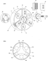
図6Aは、フロントボディ23、プランジャ28、マスタジョウ26及びガイドバー17の斜視図である。図6Bはフロントボディ23の背面を示している。プランジャ28とマスタジョウ26は、フロントボディ23に対して相対的にプランジャ28を後方に引き込むと、楔作用によりマスタジョウ26は径方向に移動する。複数のガイドバー17(例では3つ)は、頭部の側面に摺動面17aを有し、リング状シール17bを収容する溝が設けられている。17cはダンパー31にその端部が当接する胴部である。
6A is a perspective view of the front body 23, the plunger 28, the master jaw 26, and the guide bar 17. FIG. FIG. 6B shows the back of the front body 23. When the plunger 28 and the master jaw 26 pull the plunger 28 rearward with respect to the front body 23, the master jaw 26 moves in the radial direction by the wedge action. The plurality of guide bars 17 (three in the example) have sliding surfaces 17a on the side surfaces of the head, and are provided with grooves for receiving the ring-shaped seal 17b. Reference numeral 17 c denotes a body whose end abuts on the damper 31.
フロントボディ23には、等角度間隔に複数のガイド孔23b(例では3つ)が設けられており、ガイドバー17が収容されている。ガイド孔23bの前方側の内周面は、ガイドバー17の摺動面17aに沿って、フロントボディ23を軸線C上に摺動可能とする摺動面23dになっている。ガイドバー17の中央の貫通孔17dは、図示しない工作機械のスピンドルに対して直接的にあるいは、スピンドルに固定されたバックプレートに対してガイドバー17を固定するボルト16を収容する。ガイドバー17が摺動面23dを摺動するためには、摺動面17aと摺動面23dの間で少なくとも微少な空間が必要で有り、この微少な範囲において、軸線Cに対して傾くようにフロントボディ23は移動可能である。
The front body 23 is provided with a plurality of guide holes 23b (three in the example) at equal angular intervals, and the guide bars 17 are accommodated. An inner peripheral surface on the front side of the guide hole 23b is a sliding surface 23d that enables the front body 23 to slide on the axis C along the sliding surface 17a of the guide bar 17. The central through hole 17d of the guide bar 17 accommodates a bolt 16 for fixing the guide bar 17 directly to a spindle of a machine tool (not shown) or to a back plate fixed to the spindle. In order for the guide bar 17 to slide on the sliding surface 23d, at least a minute space is required between the sliding surface 17a and the sliding surface 23d, and in this minute range, it is inclined with respect to the axis C The front body 23 is movable.
図6Bにおいて、フロントボディ23の背面には、等角度間隔に3つの座面23c(第2の座面)が設けられている。座面23cは、マスタジョウ26の背後であり、リアボディ22の座面22aの個数と同じく3箇所に設けられる(3個はマスタジョウ26の個数でもある)。座面23cは、同周上の他の箇所23fに比べて、後方側(図6Bにおいて紙面前側)に突出している。座面23c以外の箇所で平面状のダンパー31の変形を許容するための空間を確保するためである。座面23cには、ダンパー31の貫通孔31aを介してボルト36(第2のボルト)が締結される孔23eが設けられている。
In FIG. 6B, the back surface of the front body 23 is provided with three seating surfaces 23c (second seating surfaces) at equal angular intervals. The seat surfaces 23c are provided behind the master jaw 26 and at three locations similar to the number of the seat surfaces 22a of the rear body 22 (three are also the number of the master jaws 26). The seating surface 23c protrudes to the rear side (the front side in the drawing of FIG. 6B) compared to the other portion 23f on the same circumference. This is to secure a space for permitting deformation of the flat damper 31 at a place other than the seating surface 23c. The seat 23c is provided with a hole 23e to which a bolt 36 (second bolt) is fastened via the through hole 31a of the damper 31.
図4,図5及び図6を参照すると、ダンパー31は貫通孔31aの位置で、当該貫通孔31aにボルト36が挿入され、フロントボディ23の座面23cに対してボルト36により締結されている。ボルト36の頭部は、リアボディ22に設けられた逃げ孔22eに余裕を持って収容されている。ダンパー31は、貫通孔31aを挟んでその両脇隣にある貫通孔31c、31dの位置で、貫通孔31dにはボルト29が挿入され、若しくは貫通孔31cにはボルト16が挿入され、図示しない工作機械のスピンドル或いはリアボディ22の座面22aに対してボルト29若しくはボルト16 ( 第1のボルト ) により締結されている。さらに、ガイドバー17が座面22aに対してボルト16 ( 第2のボルト ) により締結されている。
Referring to FIGS. 4, 5 and 6, at the position of the through hole 31a, the damper 31 has the bolt 36 inserted in the through hole 31a and is fastened to the seating surface 23c of the front body 23 by the bolt 36. . The head of the bolt 36 is accommodated in a clearance hole 22 e provided in the rear body 22 with a margin. The damper 31 has a bolt 29 inserted in the through hole 31 d or a bolt 16 inserted in the through hole 31 c at positions of the through holes 31 c and 31 d adjacent to both sides of the through hole 31 a, not shown. The bearing surface 22a of the spindle or rear body 22 of the machine tool is fastened by a bolt 29 or a bolt 16 (first bolt). Furthermore, the guide bar 17 is fastened to the bearing surface 22a by a bolt 16 (second bolt).
ダンパー31はリング状であるので(図5参照)、リアボディ22、フロントボディ23、リアボディ22、フロントボディ23の順番に、円周方向に一周する円周上で互い違いに固定するようになっている。このように、間隔を開けて設けられた座面22aの間をダンパー31が橋渡し状に配置され、其々の座面22aに対してボルト16によりダンパー31が締結される。隣り合う座面22aの間でダンパー31が、フロントボディ23の座面23cに対してボルト36により締結される。ダンパー31が隣り合う座面22aにより橋渡しされる位置は、実施形態では3箇所であるが3箇所以上としても良い。
Since the dampers 31 have a ring shape (see FIG. 5), the rear body 22, the front body 23, the rear body 22, and the front body 23 are alternately fixed in order in the circumferential direction. . Thus, the dampers 31 are arranged in a bridge-like manner between the bearing surfaces 22a provided at intervals, and the dampers 31 are fastened by the bolts 16 to the respective bearing surfaces 22a. The damper 31 is fastened to the seating surface 23c of the front body 23 by bolts 36 between the seating surfaces 22a adjacent to each other. The positions at which the dampers 31 are bridged by the adjacent seating surfaces 22a are three in the embodiment but may be three or more.
図4Bを参照して固定状態を説明すると、まず、リアボディ22はスピンドル或いはバックプレートに対して、ボルト16により(ガイドバー17を挟んで)締結されている。ダンパー31はリアボディ22とガイドバー17に挟まれてボルト29により締結されている。フロントボディ23はダンパー31にボルト36により締結されている。よって、フロントボディ23はスピンドルに対して間接的に固定されている。ダンパー31は、各ボルト16、29、36によって締結された状態であるので、軸線Cを中心とした径方向にはガタ付きが無く、軸線C方向(後述のように軸線Cに対する微少な傾きを含む)にのみリアボディ22に対して相対的にフロントボディ23の揺動を許容する。ダンパー31は薄いので軸線Cに平行な方向には剛性が低く撓みやすい。しかし、ダンパー31の薄さは、軸線Cを中心とする径方向の変形(変位)に、影響しにくい。つまり、軸線Cを中心とする径方向におけるダンパー31の剛性は、軸線Cに平行な方向におけるダンパー31の剛性よりも、高くなっている。このため、ダンパー31は軸線Cに平行な方向には変形(変位)しやすいが、ダンパー31は軸線Cを中心とする径方向には変形(変位)しにくい。
The fixed state is described with reference to FIG. 4B. First, the rear body 22 is fastened to the spindle or the back plate by bolts 16 (with the guide bar 17 interposed therebetween). The damper 31 is sandwiched between the rear body 22 and the guide bar 17 and fastened by a bolt 29. The front body 23 is fastened to the damper 31 by a bolt 36. Thus, the front body 23 is indirectly fixed to the spindle. Since the damper 31 is in a state of being fastened by the bolts 16, 29, 36, there is no rattling in the radial direction centering on the axis C, and a slight inclination with respect to the axis C as described later And allows swinging of the front body 23 relative to the rear body 22 only. Since the damper 31 is thin, its rigidity is low in the direction parallel to the axis C and it is easily bent. However, the thinness of the damper 31 hardly affects the deformation (displacement) in the radial direction about the axis C. That is, the rigidity of the damper 31 in the radial direction about the axis C is higher than the rigidity of the damper 31 in the direction parallel to the axis C. Therefore, the damper 31 is easily deformed (displaced) in the direction parallel to the axis C, but the damper 31 is not easily deformed (displaced) in the radial direction about the axis C.
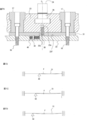
図7は、チャック200による把握精度の補正を行う構造を説明する図である。図7Aは、図4AにおけるX-X断面を示すものである。X-X断面は、溝22bに沿って切断して、リアボディ22の外周側から見た図である。ダンパー31は、隣合う座面22aの間で、1つの座面23cからの荷重を支えている。シリンダ50の推力Fにより、フロントボディ23を軸線C上で移動させる力が加わると、ダンパー31は、扇状部分22fの空間内に変形する。調整螺子41は、リアボディ22の外周面から回転させることが可能である。調整螺子41を回転させることにより、摺動子42の位置が変更される。その結果、ダンパー31が摺動子42に接触する位置が変更されることにより、ダンパー31のバネ定数を任意に変化させることが出来る。尚、摺動子42の背面側はリアボディ22に接触して、ダンパー31からの圧縮力をリアボディ22に移すようにしている。
FIG. 7 is a view for explaining a structure for correcting the grasping accuracy by the chuck 200. As shown in FIG. FIG. 7A shows an XX cross section in FIG. 4A. The XX cross section is a view taken along the groove 22 b and viewed from the outer peripheral side of the rear body 22. The damper 31 supports the load from one bearing surface 23c between the adjacent bearing surfaces 22a. When a force for moving the front body 23 on the axis C is applied by the thrust F of the cylinder 50, the damper 31 deforms into the space of the fan-shaped portion 22f. The adjustment screw 41 can be rotated from the outer peripheral surface of the rear body 22. By rotating the adjusting screw 41, the position of the slider 42 is changed. As a result, by changing the position at which the damper 31 contacts the slider 42, the spring constant of the damper 31 can be arbitrarily changed. The back side of the slider 42 is in contact with the rear body 22 to transfer the compression force from the damper 31 to the rear body 22.
図7B~図7Dは、3つの座面23cの位置におけるダンパー31の状態の変位を模式的に示している。図7Bは摺動子42が中央(座面23cの固定位置)に寄った状態、図7C、図7Dは中央から離れた状態である。シリンダ50の推力Fにより、フロントボディ23を軸線C上で移動させる力が加わると、ダンパー31は、扇状部分22fの空間内に変形する。摺動子42は、その背面をリアボディ22がバックアップしているため、図7Bにおいてはダンパー31が変形する長さが短く、図7C、図7Dでは長くなる。よって、ダンパー31は、座面23cの固定位置においてバネ定数が変更可能である。
7B to 7D schematically show the displacement of the state of the damper 31 at the positions of the three seating surfaces 23c. FIG. 7B shows a state in which the slider 42 is in the center (fixed position of the seating surface 23c), and FIGS. 7C and 7D are in a state away from the center. When a force for moving the front body 23 on the axis C is applied by the thrust F of the cylinder 50, the damper 31 deforms into the space of the fan-shaped portion 22f. Since the rear body 22 backs up the rear surface of the slider 42, the length of deformation of the damper 31 is short in FIG. 7B and is long in FIGS. 7C and 7D. Therefore, the spring constant of the damper 31 can be changed at the fixed position of the seating surface 23c.
次に、チャック200の把握精度の補正方法に係る補正工程を説明する。
まず、シリンダ50の推力Fをかけるとフロントボディからの力でダンパー31は弾性変形してフロントボディ23は左方向に引き込まれる。ボルト16がガイドバー17を挟んでリアボディ22をスピンドルに締結しているので、リアボディ22のZ方向の姿勢は維持されている。3箇所の摺動子42の位置を夫々調整螺子41によって制御する。ダンパー31のバネ定数を小さくすると変形量は大きくなり同じシリンダ50の推力においてもフロントボディ23が軸線C上を移動する距離が大きくなる。一方、バネ定数を大きくすると変形量は小さくなり、同じシリンダ50の推力においてもフロントボディ23が軸線C上を移動する距離が小さくなる。したがって、箇所の摺動子42の位置を夫々調整螺子41により互いに変更することにより、図4Aの矢印Qにより示すように、フロントボディ23を軸線Cのまわり360度の方向に微妙に傾けることができる。ワークの芯が中心を向くように、調整螺子41、摺動子42により、ダンパー31の変形量に差をつけることでフロントボディ23を微小に傾かせる。これによりワークの芯調整ができる。このように、ワークを実際にジョウ24のワーク把握面に把握させた時のワークの芯を軸線Cに合わせるように、調整螺子41を用いて極めて微妙な調整をすることができる。本実施形態においては、摺動子42の位置を等角度間隔に設定したが、少なくとも3つの摺動子42を結ぶ直線で囲まれる図形の中に、軸線Cが入るような位置関係であれば良い。本実施形態によれば、ジョウ24にワークを保持した時のワークの芯が軸線C上に配置されるように、フロントボディ23を軸線Cに対して傾けることで、ジョウ24に対して成形を加える必要無く、把握精度を確保することができる。なお、フロントボディを傾ける行為は、ジョウにワークを実際に保持したまま行っても良いし、ジョウにワークを保持した状態でワークの振れを測定し、その後ワークを取り外してから行っても良い。 Next, the correction process according to the method of correcting the grasping accuracy of thechuck 200 will be described.
First, when the thrust F of thecylinder 50 is applied, the damper 31 is elastically deformed by the force from the front body, and the front body 23 is pulled leftward. Since the bolt 16 fastens the rear body 22 to the spindle with the guide bar 17 in between, the attitude of the rear body 22 in the Z direction is maintained. The positions of the three sliders 42 are controlled by the adjusting screws 41 respectively. When the spring constant of the damper 31 is reduced, the amount of deformation is increased, and the distance by which the front body 23 moves on the axis C is increased even with the same thrust of the cylinder 50. On the other hand, when the spring constant is increased, the amount of deformation decreases, and the distance by which the front body 23 moves on the axis C also decreases with the same thrust of the cylinder 50. Therefore, the front body 23 may be slightly inclined in the direction of 360 degrees around the axis C as shown by the arrow Q in FIG. it can. The front body 23 is slightly inclined by making the amount of deformation of the damper 31 different by the adjusting screw 41 and the slider 42 so that the core of the work is directed to the center. This makes it possible to adjust the work core. In this way, the adjustment screw 41 can be used to make extremely fine adjustment so that the core of the workpiece when the workpiece is actually grasped on the workpiece gripping surface of the jaw 24 is aligned with the axis C. In the present embodiment, the positions of the sliders 42 are set at equal angular intervals, but if the positional relationship is such that the axis C is included in the figure enclosed by the straight line connecting at least three sliders 42 good. According to the present embodiment, the front body 23 is inclined with respect to the axis C to form the jaw 24 so that the core of the work is held on the axis C when the jaw 24 holds the work. There is no need to add it, and the grasping accuracy can be secured. In addition, the act of tilting the front body may be performed while actually holding the work on the jaw, or may be performed after measuring the movement of the work while holding the work on the jaw and then removing the work.
まず、シリンダ50の推力Fをかけるとフロントボディからの力でダンパー31は弾性変形してフロントボディ23は左方向に引き込まれる。ボルト16がガイドバー17を挟んでリアボディ22をスピンドルに締結しているので、リアボディ22のZ方向の姿勢は維持されている。3箇所の摺動子42の位置を夫々調整螺子41によって制御する。ダンパー31のバネ定数を小さくすると変形量は大きくなり同じシリンダ50の推力においてもフロントボディ23が軸線C上を移動する距離が大きくなる。一方、バネ定数を大きくすると変形量は小さくなり、同じシリンダ50の推力においてもフロントボディ23が軸線C上を移動する距離が小さくなる。したがって、箇所の摺動子42の位置を夫々調整螺子41により互いに変更することにより、図4Aの矢印Qにより示すように、フロントボディ23を軸線Cのまわり360度の方向に微妙に傾けることができる。ワークの芯が中心を向くように、調整螺子41、摺動子42により、ダンパー31の変形量に差をつけることでフロントボディ23を微小に傾かせる。これによりワークの芯調整ができる。このように、ワークを実際にジョウ24のワーク把握面に把握させた時のワークの芯を軸線Cに合わせるように、調整螺子41を用いて極めて微妙な調整をすることができる。本実施形態においては、摺動子42の位置を等角度間隔に設定したが、少なくとも3つの摺動子42を結ぶ直線で囲まれる図形の中に、軸線Cが入るような位置関係であれば良い。本実施形態によれば、ジョウ24にワークを保持した時のワークの芯が軸線C上に配置されるように、フロントボディ23を軸線Cに対して傾けることで、ジョウ24に対して成形を加える必要無く、把握精度を確保することができる。なお、フロントボディを傾ける行為は、ジョウにワークを実際に保持したまま行っても良いし、ジョウにワークを保持した状態でワークの振れを測定し、その後ワークを取り外してから行っても良い。 Next, the correction process according to the method of correcting the grasping accuracy of the
First, when the thrust F of the
実施形態3.
図8に実施形態3のチャック300を示す。実施形態1、2と同じ構成については、同一の引用符号が付されている。実施形態2においては、調整螺子41をリアボディ22の外周面から回転させることにより、摺動子42の位置を変更してダンパー31のバネ定数を変化させた。実施形態3では、フロントボディ43の前面側(図8Aの右側)から調整子51を操作することにより、摺動子51bの位置を変更してダンパー45のバネ定数を変化させる。Embodiment 3
Thechuck 300 of the third embodiment is shown in FIG. The same components as in the first and second embodiments are given the same reference numerals. In the second embodiment, by rotating the adjustment screw 41 from the outer peripheral surface of the rear body 22, the position of the slider 42 is changed to change the spring constant of the damper 31. In the third embodiment, by operating the adjuster 51 from the front side (right side in FIG. 8A) of the front body 43, the position of the slider 51b is changed to change the spring constant of the damper 45.
図8に実施形態3のチャック300を示す。実施形態1、2と同じ構成については、同一の引用符号が付されている。実施形態2においては、調整螺子41をリアボディ22の外周面から回転させることにより、摺動子42の位置を変更してダンパー31のバネ定数を変化させた。実施形態3では、フロントボディ43の前面側(図8Aの右側)から調整子51を操作することにより、摺動子51bの位置を変更してダンパー45のバネ定数を変化させる。
The
図8Aにおいて、フロントボディ43の前面側に等角度間隔に設けられた複数(実施形態では3つ)のメンテナンス孔56が設けられている。メンテナンス孔56は、通常は封止ボルト52が調整子51の雌ネジ孔51dへ螺合されており、封止されている状態である。図8Bにおいて、メンテナンス孔56から、封止ボルト52を取り出すと、調整子51の操作端51aが現れる。封止ボルト52は、切削粉の侵入を防ぐものである。操作端51aは六角レンチ55を受ける雌溝であり、フロントボディ43とダンパー45の間に存在する調整子51を回転操作することができる。雌ネジ孔51dは、操作端51aの奥側に設けられている。調整子51は、フロントボディ43を貫通してダンパー45に正対している。調整子51は、図8Dに示すように、ダンパー45に正対する側に摺動子51bを有しており、ダンパー45が変形する過程で摺動子51bがダンパー45に接触する。フロントボディ43側には、摺動子51bが揺動するためのリセス53aが設けられている。調整子51を回転操作すると、摺動子51bがダンパー45に接触する位置が変わり、ダンパー45のバネ定数を変化させることができる。尚、摺動子51bの背面側はフロントボディ43に接触して、ダンパー45からの押付力をフロントボディ43に移すようにしている。
In FIG. 8A, a plurality of (three in the embodiment) maintenance holes 56 provided at equal angular intervals on the front side of the front body 43 are provided. In the maintenance hole 56, the sealing bolt 52 is normally screwed into the female screw hole 51d of the adjuster 51, and is in a sealed state. In FIG. 8B, when the sealing bolt 52 is taken out from the maintenance hole 56, the operation end 51a of the adjuster 51 appears. The sealing bolt 52 prevents penetration of cutting powder. The operation end 51 a is a female groove for receiving the hexagonal wrench 55, and can rotate the adjuster 51 existing between the front body 43 and the damper 45. The female screw hole 51d is provided on the back side of the operation end 51a. The adjuster 51 penetrates the front body 43 and faces the damper 45. As shown in FIG. 8D, the adjuster 51 has a slider 51b on the side directly facing the damper 45, and the slider 51b contacts the damper 45 in the process of deformation of the damper 45. A recess 53a for swinging the slider 51b is provided on the front body 43 side. When the adjuster 51 is rotated, the position at which the slider 51b contacts the damper 45 changes, and the spring constant of the damper 45 can be changed. The back side of the slider 51b is in contact with the front body 43 to transfer the pressing force from the damper 45 to the front body 43.
調整子51の回転角度が離散的に変更しやすいように、リセス53a側には等角度間隔にラッチングノッチ53bが設けられ、調整子51にはラッチングノッチ53bに対して弾性的に進退する爪51cが設けられている。そして、六角レンチ55を用いて調整子51の回転角度を調整した後に、封止ボルト52を締め付けることで、調整子51の固定を行うことができる。また、前述の実施形態では、封止ボルト52を締め付けることで調整子51の固定をおこなっているが、調整子51を固定する他の実施形態として、フロントボディ43の側面から調整子51の側面に到る雌ネジ孔を設け、当該雌ネジ孔にボルトを螺入することにより固定しても良い。
In order to make it easy to discretely change the rotational angle of the adjuster 51, latching notches 53b are provided at equal angular intervals on the recess 53a side, and the adjuster 51 has claws 51c elastically advancing and retracting with respect to the latching notch 53b. Is provided. Then, after adjusting the rotation angle of the adjuster 51 using the hexagonal wrench 55, the adjuster 51 can be fixed by tightening the sealing bolt 52. Further, in the above-described embodiment, the adjuster 51 is fixed by tightening the sealing bolt 52. However, as another embodiment for fixing the adjuster 51, the side surface of the adjuster 51 from the side surface of the front body 43 It is also possible to provide a female screw hole leading to the above and fix it by screwing a bolt into the female screw hole.
実施形態3によれば、殆どの工作機械において露出することが多いフロントボディ43の前面側から、摺動子51bの位置を変更してダンパー45のバネ定数を変化させることができるという効果がある。また、実施形態2のようにリアボディ22に調整螺子41と摺動子42を設けるよりも、部品点数が少なくでき、コストを下げることができるという効果もある。
According to the third embodiment, the spring constant of the damper 45 can be changed by changing the position of the slider 51b from the front side of the front body 43 which is often exposed in most machine tools. . Further, as compared with the case where the adjustment screw 41 and the slide 42 are provided on the rear body 22 as in the second embodiment, the number of parts can be reduced, and the cost can be reduced.
実施形態4.
実施形態4のチャック400を図9に示す。実施形態4は、実施形態1の変形例である。実施形態1では、リアボディ2の側面若しくはフロントボディ3の各ガイド孔に挿入されたガイドバー7の側面を、複数の調整ボルト13によりフロントボディ3の側面から押し付けることにより、軸線Cを中心とした径方向にフロントボディ3を移動したが、実施形態4ではフロントボディ63の前面側から調整螺子61を操作して、軸線Cを中心とした径方向にフロントボディ63を移動するものである。実施形態1と同様な構成については、同一の引用符号が付されている。Embodiment 4
Thechuck 400 of the fourth embodiment is shown in FIG. The fourth embodiment is a modification of the first embodiment. In the first embodiment, the axis C is centered by pressing the side surface of the rear body 2 or the side surface of the guide bar 7 inserted in each guide hole of the front body 3 from the side surface of the front body 3 by a plurality of adjustment bolts 13. The front body 3 is moved in the radial direction, but in the fourth embodiment, the adjustment screw 61 is operated from the front side of the front body 63 to move the front body 63 in the radial direction about the axis C. The same components as those in the first embodiment are given the same reference numerals.
実施形態4のチャック400を図9に示す。実施形態4は、実施形態1の変形例である。実施形態1では、リアボディ2の側面若しくはフロントボディ3の各ガイド孔に挿入されたガイドバー7の側面を、複数の調整ボルト13によりフロントボディ3の側面から押し付けることにより、軸線Cを中心とした径方向にフロントボディ3を移動したが、実施形態4ではフロントボディ63の前面側から調整螺子61を操作して、軸線Cを中心とした径方向にフロントボディ63を移動するものである。実施形態1と同様な構成については、同一の引用符号が付されている。
The
調整螺子61は、チャック400に対して等角度間隔に複数(実施形態では3つ)設けられており、その操作端61aがフロントボディ63の前面側に露出している。操作端61aは六角レンチを受ける雌溝であり、調整螺子61を回転操作することができる。調整螺子61は、軸部61bに螺子を有しており、フロントボディ63の中を軸線Cの向きで進退可能である。調整螺子61の頭部61cはテーパー状になっており、リアボディ62側に設けられた傾斜状の摺動面62aを摺動する。頭部61cが軸線Cの向きで進退することで、摺動面62aを摺動し、軸線Cを中心とした径方向にフロントボディ63を移動させる。
A plurality of (three in the embodiment) adjustment screws 61 are provided at equal angular intervals with respect to the chuck 400, and the operation end 61 a is exposed on the front side of the front body 63. The operation end 61 a is a female groove for receiving a hexagonal wrench, and can rotate the adjusting screw 61. The adjusting screw 61 has a screw in the shaft portion 61 b, and can advance and retract in the front body 63 in the direction of the axis C. The head portion 61 c of the adjusting screw 61 is tapered, and slides on an inclined sliding surface 62 a provided on the rear body 62 side. The head 61 c advances and retracts in the direction of the axis C, thereby sliding the sliding surface 62 a and moving the front body 63 in the radial direction about the axis C.
1、20:ボディ、2、22、62:リアボディ、3、23、43、63:フロントボディ、4、24:ジョウ、5、23b:ガイド孔、6、26:マスタジョウ、7、17:ガイドバー、8、28:プランジャ、9:バネ、11、16、29、36:ボルト、12:調整螺子孔、13:調整ボルト、22a、23c:座面、31、45:ダンパー、50:シリンダ、41:調整螺子、42:摺動子、51:調整子、61:調整螺子、100、200:チャック
1, 20: Body, 2, 22, 62: Rear body, 3, 23, 43, 63: Front body, 4, 24: Jaw, 5, 23b: Guide hole, 6, 26: Master Jaw, 7, 17: Guide Bar 8, 28: plunger, 9: spring, 11, 16, 29, 36: bolt, 12: adjusting screw hole, 13: adjusting bolt, 22a, 23c: seating surface, 31, 45: damper, 50: cylinder, 41: Adjustment screw, 42: Slider, 51: Adjuster, 61: Adjustment screw, 100, 200: Chuck
Claims (8)
- 補正工程を備える、チャックの補正方法であって、
前記チャックは、ボディと、プランジャと、ジョウとを備え、
前記ボディは、リアボディと該リアボディの前方側に配置されたフロントボディとを有し
前記プランジャは、該ボディ内に設けられ、前記ボディの軸線上を移動するように構成され、
前記ジョウは、前記プランジャの移動によって前記フロントボディにガイドされて前記軸線を中心とした径方向へ移動するように構成され、
前記補正工程では、
前記ジョウにワークを把握させたときにおいて、
前記軸線に対する前記リアボディの位置を維持しながら前記軸線を中心とした径方向に前記フロントボディを移動させる、又は、前記軸線に対する前記リアボディの位置を維持しながら前記フロントボディを前記軸線に対して傾けさせる、方法。 A chuck correction method comprising a correction step, comprising:
The chuck includes a body, a plunger, and a jaw.
The body has a rear body and a front body disposed on the front side of the rear body. The plunger is provided in the body and configured to move along an axis of the body.
The jaw is configured to be guided by the front body by movement of the plunger and move in a radial direction about the axis.
In the correction process,
When you let the jaws grasp the work,
The front body is moved in a radial direction about the axis while maintaining the position of the rear body with respect to the axis, or the front body is inclined with respect to the axis while maintaining the position of the rear body with respect to the axis How to make it happen. - 請求項1に記載の方法において、
前記チャックは、前記リアボディから前記フロントボディに向けて設けられたガイドバーを有し、
前記ガイドバーは、前記フロントボディに設けられたガイド孔に挿入される、方法。 In the method according to claim 1,
The chuck has a guide bar provided from the rear body to the front body,
The method wherein the guide bar is inserted into a guide hole provided in the front body. - 請求項1又は請求項2に記載の方法において、
前記チャックは、前記フロントボディを前記リアボディに固定するボルトを有し、
前記ボルトを緩めた状態で前記フロントボディを前記径方向に移動させ、移動が終わった段階で前記ボルトを締結する、方法。 In the method according to claim 1 or claim 2,
The chuck has a bolt for securing the front body to the rear body,
Moving the front body in the radial direction with the bolt loosened, and tightening the bolt when the movement is finished. - 請求項2に記載の方法において、
前記フロントボディを前記リアボディに押しつけておく付勢手段を前記ガイドバーに装着する、方法。 In the method according to claim 2,
Mounting the urging means for pressing the front body against the rear body to the guide bar. - 請求項2又は請求項4に記載の方法において、
調整ボルトを前記フロントボディに挿入することによって、前記調整ボルトを前記リアボディの側面若しくは前記ガイドバーの側面に押し付け、前記フロントボディを前記径方向に移動させる、方法。 In the method according to claim 2 or claim 4,
And inserting the adjusting bolt into the front body to press the adjusting bolt against the side surface of the rear body or the side surface of the guide bar to move the front body in the radial direction. - 請求項3に記載の方法において、
前記リアボディに傾斜状の摺動面が設けられ、
前記フロントボディの前面側からの回転操作により前記フロントボディの中を進退可能であって、テーパー状の頭部が前記摺動面を摺動する調整螺子を有し、
前記調整螺子を進退させることで、テーパー状の頭部が前記摺動面を摺動し、前記フロントボディを前記径方向に移動させる、方法。 In the method according to claim 3,
An inclined sliding surface is provided on the rear body,
The inside of the front body can be advanced and retracted by a rotation operation from the front side of the front body, and a tapered head has an adjusting screw that slides on the sliding surface,
A method wherein the tapered head slides on the sliding surface by moving the adjusting screw back and forth, thereby moving the front body in the radial direction. - 請求項1~請求項6の何れか1つに記載の方法において、
前記リアボディは、間隔を開けて設けられた第1の座面の間をダンパーが橋渡し状に配置され、其々の座面に対して第1のボルトにより前記ダンパーが締結されており、
前記フロントボディは、その背面に設けられた第2の座面に対して、前記第1の座面の間で第2のボルトにより前記ダンパーが締結されて、かつ隣り合う前記第1の座面の間を橋渡し状に配置された前記ダンパーに対して、前記ダンパーの変形長を変更する摺動子が設けられており、
前記補正工程では、
前記ジョウにワークを把握させたときにおいて、前記摺動子の位置を変更して前記フロントボディを前記軸線に対して傾ける、方法。 In the method according to any one of claims 1 to 6,
In the rear body, dampers are arranged like a bridge between first seating surfaces provided at intervals, and the dampers are fastened to respective seating surfaces by first bolts,
The front body has a second seating surface provided on the rear surface, and the damper is fastened between the first seating surfaces by a second bolt, and the adjacent first seating surfaces A slider for changing the deformation length of the damper, provided to the damper arranged in a bridge-like manner between the
In the correction process,
When the jaw is made to grasp a work, the position of the slider is changed to tilt the front body with respect to the axis. - 請求項7に記載の方法において、
前記ダンパーが橋渡し状に配置される位置を、等角度間隔に少なくとも3箇所以上配置する、方法。 In the method according to claim 7,
A method, wherein the positions at which the dampers are arranged in a bridge-like manner are arranged at at least three places at equal angular intervals.
Priority Applications (5)
| Application Number | Priority Date | Filing Date | Title |
|---|---|---|---|
| CN201880040247.2A CN110753594B (en) | 2017-08-07 | 2018-06-15 | Method for correcting chuck |
| KR1020207003831A KR102523473B1 (en) | 2017-08-07 | 2018-06-15 | How to calibrate the chuck |
| JP2019535003A JP7171576B2 (en) | 2017-08-07 | 2018-06-15 | Chuck compensation method |
| US16/635,285 US11471955B2 (en) | 2017-08-07 | 2018-06-15 | Chuck correction method |
| EP18842892.4A EP3666431A4 (en) | 2017-08-07 | 2018-06-15 | Chuck correction method |
Applications Claiming Priority (2)
| Application Number | Priority Date | Filing Date | Title |
|---|---|---|---|
| JP2017-152215 | 2017-08-07 | ||
| JP2017152215 | 2017-08-07 |
Publications (1)
| Publication Number | Publication Date |
|---|---|
| WO2019031059A1 true WO2019031059A1 (en) | 2019-02-14 |
Family
ID=65272058
Family Applications (1)
| Application Number | Title | Priority Date | Filing Date |
|---|---|---|---|
| PCT/JP2018/022862 WO2019031059A1 (en) | 2017-08-07 | 2018-06-15 | Chuck correction method |
Country Status (7)
| Country | Link |
|---|---|
| US (1) | US11471955B2 (en) |
| EP (1) | EP3666431A4 (en) |
| JP (1) | JP7171576B2 (en) |
| KR (1) | KR102523473B1 (en) |
| CN (1) | CN110753594B (en) |
| TW (1) | TWI757515B (en) |
| WO (1) | WO2019031059A1 (en) |
Families Citing this family (2)
| Publication number | Priority date | Publication date | Assignee | Title |
|---|---|---|---|---|
| CN114029560B (en) * | 2021-11-30 | 2023-07-14 | 四川大学 | Cutter combination for machining cylindrical gear with hyperbolic circular arc toothed line and machining method |
| CN114589365A (en) * | 2022-04-21 | 2022-06-07 | 河南航天液压气动技术有限公司 | Light-load working condition floating adjusting device |
Citations (5)
| Publication number | Priority date | Publication date | Assignee | Title |
|---|---|---|---|---|
| US3460849A (en) * | 1966-01-11 | 1969-08-12 | Sp Mfg Corp | Variable force chuck construction |
| JP2003001507A (en) * | 2001-06-21 | 2003-01-08 | Kitagawa Iron Works Co Ltd | High accuracy retracting chuck |
| JP2009184083A (en) * | 2008-02-08 | 2009-08-20 | Howa Mach Ltd | Core compensating chuck |
| JP2011110676A (en) | 2009-11-30 | 2011-06-09 | Howa Mach Ltd | Draw-down chuck |
| JP2015058528A (en) * | 2013-09-20 | 2015-03-30 | 株式会社北川鉄工所 | Retractable chuck |
Family Cites Families (21)
| Publication number | Priority date | Publication date | Assignee | Title |
|---|---|---|---|---|
| US2447711A (en) * | 1946-01-16 | 1948-08-24 | Mikis Ernest | Precision leveling chuck |
| CH293499A (en) * | 1951-03-01 | 1953-09-30 | Amann Philipp | Centering device. |
| US2984494A (en) * | 1959-12-18 | 1961-05-16 | Frank A Alston | Adjustable mounts for self-centering chucks |
| US3088746A (en) * | 1960-12-08 | 1963-05-07 | Whiton Machine Company | Radially adjustable chuck |
| US3129950A (en) * | 1962-07-16 | 1964-04-21 | Cushman Chuck Co | Center-adjustable chuck adapter |
| US3178192A (en) * | 1963-02-07 | 1965-04-13 | Sp Mfg Corp | Adjustable universal chuck |
| US3259394A (en) * | 1964-04-13 | 1966-07-05 | Buck Tool Co | Radially adjustable chuck |
| US3357711A (en) * | 1965-01-05 | 1967-12-12 | Fischer Walter Ernst | Eccentrically adjustable chuck |
| US3460847A (en) * | 1965-06-10 | 1969-08-12 | Woodworth Co N A | Fixture mounting assembly |
| DE2057900A1 (en) * | 1970-11-25 | 1972-05-31 | Norbert Schlicksupp | Lathe chuck flange |
| US4645219A (en) * | 1984-12-29 | 1987-02-24 | Index-Werke Komm. Ges. Hahn & Tessky | Chuck |
| JP2001219309A (en) | 2000-02-07 | 2001-08-14 | Howa Mach Ltd | Chuck |
| US6425584B1 (en) | 2000-09-01 | 2002-07-30 | Illinois Tool Works, Inc. | Sliding jaw chuck assembly |
| DE20102880U1 (en) | 2001-02-16 | 2001-07-19 | Robert Schroeder Gmbh & Co Kg | Jaw |
| CN200998775Y (en) * | 2007-02-08 | 2008-01-02 | 李吉伟 | Universal machine chuck |
| CN201483016U (en) * | 2009-06-18 | 2010-05-26 | 中信戴卡轮毂制造股份有限公司 | Adjustable radial positioning chunk plate of sleeping car |
| DE102010041054A1 (en) * | 2010-04-01 | 2011-10-06 | Schunk Gmbh & Co. Kg Spann- Und Greiftechnik | Centering device for centering a chuck on a rotating spindle and associated locking device |
| CN101829794B (en) * | 2010-05-28 | 2012-08-08 | 中国航天科技集团公司长征机械厂 | Six-claw double-linkage self-centering chuck |
| CN202317093U (en) * | 2011-09-15 | 2012-07-11 | 吴红 | Chuck for machine tool |
| CN104722789A (en) * | 2015-03-19 | 2015-06-24 | 吴江市菀坪宝得利缝制设备机械厂 | Adjustable eccentric device for self-centering chuck |
| CN205363682U (en) * | 2016-02-16 | 2016-07-06 | 山东省特种设备检验研究院济宁分院 | Automatic safety valve operating test seat chuck of alignment |
-
2018
- 2018-06-15 KR KR1020207003831A patent/KR102523473B1/en active IP Right Grant
- 2018-06-15 WO PCT/JP2018/022862 patent/WO2019031059A1/en unknown
- 2018-06-15 US US16/635,285 patent/US11471955B2/en active Active
- 2018-06-15 EP EP18842892.4A patent/EP3666431A4/en active Pending
- 2018-06-15 JP JP2019535003A patent/JP7171576B2/en active Active
- 2018-06-15 CN CN201880040247.2A patent/CN110753594B/en active Active
- 2018-06-20 TW TW107121081A patent/TWI757515B/en active
Patent Citations (5)
| Publication number | Priority date | Publication date | Assignee | Title |
|---|---|---|---|---|
| US3460849A (en) * | 1966-01-11 | 1969-08-12 | Sp Mfg Corp | Variable force chuck construction |
| JP2003001507A (en) * | 2001-06-21 | 2003-01-08 | Kitagawa Iron Works Co Ltd | High accuracy retracting chuck |
| JP2009184083A (en) * | 2008-02-08 | 2009-08-20 | Howa Mach Ltd | Core compensating chuck |
| JP2011110676A (en) | 2009-11-30 | 2011-06-09 | Howa Mach Ltd | Draw-down chuck |
| JP2015058528A (en) * | 2013-09-20 | 2015-03-30 | 株式会社北川鉄工所 | Retractable chuck |
Non-Patent Citations (1)
| Title |
|---|
| See also references of EP3666431A4 |
Also Published As
| Publication number | Publication date |
|---|---|
| KR20200038471A (en) | 2020-04-13 |
| JPWO2019031059A1 (en) | 2020-06-25 |
| TWI757515B (en) | 2022-03-11 |
| EP3666431A4 (en) | 2020-08-26 |
| US20200368825A1 (en) | 2020-11-26 |
| US11471955B2 (en) | 2022-10-18 |
| JP7171576B2 (en) | 2022-11-15 |
| CN110753594A (en) | 2020-02-04 |
| KR102523473B1 (en) | 2023-04-18 |
| EP3666431A1 (en) | 2020-06-17 |
| TW201910027A (en) | 2019-03-16 |
| CN110753594B (en) | 2021-12-14 |
Similar Documents
| Publication | Publication Date | Title |
|---|---|---|
| CN108602135B (en) | Retractable chuck | |
| US6557445B1 (en) | Tool holder and a runout correcting tool for a tool holder | |
| US20130071193A1 (en) | Flexible cartridge with precision adjustment | |
| WO2019031059A1 (en) | Chuck correction method | |
| JP4972362B2 (en) | Diaphragm chuck | |
| KR920007958B1 (en) | Tool holder | |
| JP5204992B2 (en) | Chuck device | |
| JP2006326744A (en) | Chuck pawl of chuck mechanism for lathe | |
| JP2010105121A (en) | Collet holder | |
| JP2001138162A (en) | Tool holder, and deflection correcting tool for tool holder | |
| JP4190338B2 (en) | Workpiece holding device | |
| JP2015213968A (en) | Play regulation mechanism for drilling tool | |
| JP2804696B2 (en) | Cutting tools | |
| JP2011115888A (en) | Tool holder | |
| KR102207808B1 (en) | Working machine with position correction function | |
| WO2020179674A1 (en) | Structure | |
| JPS6348324Y2 (en) | ||
| JP7288441B2 (en) | Chuck with pull-in function | |
| TWM541345U (en) | Adjustable chuck | |
| JP7130938B2 (en) | Chuck | |
| JP2998597B2 (en) | Cutting method and cutting tool | |
| JP2748847B2 (en) | Cutting tools | |
| JP3565074B2 (en) | Cutting tools | |
| JP4630048B2 (en) | Scroll chuck | |
| JPH10225806A (en) | Cutting tool for tapered peripheral surface |
Legal Events
| Date | Code | Title | Description |
|---|---|---|---|
| 121 | Ep: the epo has been informed by wipo that ep was designated in this application |
Ref document number: 18842892 Country of ref document: EP Kind code of ref document: A1 |
|
| ENP | Entry into the national phase |
Ref document number: 2019535003 Country of ref document: JP Kind code of ref document: A |
|
| NENP | Non-entry into the national phase |
Ref country code: DE |
|
| ENP | Entry into the national phase |
Ref document number: 2018842892 Country of ref document: EP Effective date: 20200309 |