JP5204992B2 - Chuck device - Google Patents
Chuck device Download PDFInfo
- Publication number
- JP5204992B2 JP5204992B2 JP2007153774A JP2007153774A JP5204992B2 JP 5204992 B2 JP5204992 B2 JP 5204992B2 JP 2007153774 A JP2007153774 A JP 2007153774A JP 2007153774 A JP2007153774 A JP 2007153774A JP 5204992 B2 JP5204992 B2 JP 5204992B2
- Authority
- JP
- Japan
- Prior art keywords
- chuck body
- cam
- chuck
- jaw
- master jaw
- Prior art date
- Legal status (The legal status is an assumption and is not a legal conclusion. Google has not performed a legal analysis and makes no representation as to the accuracy of the status listed.)
- Active
Links
- 210000000078 claw Anatomy 0.000 claims description 74
- 230000002093 peripheral effect Effects 0.000 claims description 36
- 230000001154 acute effect Effects 0.000 claims description 6
- 238000003780 insertion Methods 0.000 description 5
- 230000037431 insertion Effects 0.000 description 5
- 238000000034 method Methods 0.000 description 3
- 238000004140 cleaning Methods 0.000 description 1
- 230000000694 effects Effects 0.000 description 1
Images


Landscapes
- Gripping On Spindles (AREA)
Description
この発明は、チャック本体の中心軸周りに複数の把持爪を備えたチャック装置に関するものである。 The present invention relates to a chuck device including a plurality of gripping claws around a central axis of a chuck body.
旋盤加工等においてワークを把持するために用いられるチャック装置として、例えば、ドローバの進退等によってチャック本体の前部に設けた把持爪(ジョウ)を径方向へ動かして、その把持爪によりワークの外周部又は内周部を掴むものがある。 As a chuck device used for gripping a workpiece in lathe processing or the like, for example, a gripping claw (jou) provided at the front of the chuck body is moved in the radial direction by advancing and retreating a draw bar, and the outer periphery of the workpiece is moved by the gripping claw. Some grip the part or inner periphery.
その構成の一例を、図7に基づいて説明すると、チャック本体1の中心軸6周りに、複数の把持爪10が放射状に設けられている。そのチャック本体1の中心軸6に沿って、前記中心軸6と同心のドローバ3が軸方向進退可能に設けられている。
An example of the configuration will be described with reference to FIG. 7. A plurality of gripping
また、チャック本体1には、ドローバボルト8によって前記ドローバ3と一体に固定されてそのドローバ3とともに軸方向へ進退する駆動部材(アクチュエータ)4が設けられている。さらに、その駆動部材4に設けたフランジ部4aに、スライディングボール9を介して揺動部材(ジョウアクチュエータ)2が設けられている。揺動部材2の後端に丸棒部が形成されており、その丸棒部が前記スライディングボール9の孔に摺動自在に嵌合している。このため、前記駆動部材4の軸方向進退に伴って、その揺動部材2の前端がチャック本体1の径方向に揺動するようになっている。
Further, the chuck body 1 is provided with a drive member (actuator) 4 that is fixed integrally with the draw bar 3 by a
揺動部材2は、チャック本体1の中心軸6周りに等分方位に複数配設され、その各揺動部材2の前端に、マスタージョウ12を介してワークwを把持する把持爪10が設けられている。
A plurality of oscillating
チャック本体1に対してドローバ3が軸方向に後退すると、前記駆動部材4及び揺動部材2を介してマスタージョウ12が径方向内側へ移動する。そのマスタージョウ12とともに把持爪10が径方向内側に動いて、その把持爪10でワークwの外周部を掴み、そのワークwを、前記中心軸6と同心に把持するようになっている(例えば、特許文献1参照)。
When the draw bar 3 moves backward in the axial direction with respect to the chuck body 1, the
また、特に、引込み式チャック装置等の場合において、チャック本体1の前面にストッパ装置を設ける場合もある。このストッパ装置は、ワークwの端面がそのストッパ装置の前面に密着して、その密着により、ストッパ装置の前面及びワークwの端面が基準面として機能して、ワークwが正しい位置、正しい把持姿勢に維持されるようになっている。(例えば、特許文献2参照)。
上記のチャック装置において、把持爪10がワークwの外周面又は内周面を把持する位置、あるいは、ストッパ装置に当接し得るワークwの端面(把持の際のワークwの基準面)の位置は、そのワークwの種別、例えば、形状、大きさ等によって各々異なるものである。
In the above chuck device, the position at which the gripping
例えば、チャック本体1の中心軸6に比較的近い部分に把持爪10がワークwの外周面又は内周面を把持する部分を有するワークwもあれば、中心軸6から比較的遠い部分に、その把持する部分を有するワークwもある。また、その把持する部分のチャック本体1に対する軸方向位置も、ワークwの種別によってさまざまである。
さらに、例えば、チャック本体1の中心軸6に比較的近い部分に、前記ストッパ装置への当接部分(ワークwの基準面)を有するワークwもあれば、中心軸6から比較的遠い部分に、前記ストッパ装置への当接部分を有するワークwもある。また、その当接部分のチャック本体1に対する軸方向位置も、ワークwの種別によってさまざまである。
For example, if there is a workpiece w having a portion where the gripping
Further, for example, there is a workpiece w having a contact portion (reference surface of the workpiece w) to the stopper device in a portion relatively close to the
このため、同一のチャック装置によって、異なる種別のワークwを把持しようとすると、ワークwの種別が変わるたびに、その都度、把持爪10やそれに接続されるマスタージョウ12及び揺動部材2等、あるいはストッパ装置を取替えなければならないという問題がある。
For this reason, when trying to grip a different type of work w by the same chuck device, each time the type of the work w changes, the gripping
把持爪10やストッパ装置等の取替えの際には、その把持爪10やストッパ装置をいずれもチャック本体1に対して軸方向及び径方向への「位置ずれ」や、「がた」が生じないようにしっかりと固定しなければならない。この固定は、例えば、図7に示すように、把持爪10とマスタージョウ12とを、チャック本体1の軸方向に向くネジBで締め付けて止める手法が一般的である。
When the gripping
しかし、軸方向に向くネジBによる固定は、そのネジBの締め付け度合いの調整、管理が難しく、また、把持爪10が大きくなればネジBの数も増え、その固定に要する構造は複雑、大がかりなものになりがちである。
したがって、軸方向に向くネジBの締め付けによる固定では、チャック本体1に対する把持爪10の位置決め精度が劣るとともに、その着脱作業は面倒なものとなる。このため、チャック装置へのワークwの装着にかかる作業効率を低下させるので好ましくない。
However, the fixing with the screw B directed in the axial direction is difficult to adjust and manage the tightening degree of the screw B, and the number of the screws B increases as the
Therefore, in the fixing by tightening the screw B facing in the axial direction, the positioning accuracy of the gripping
そこで、この発明は、同一のチャック装置によって、異なる種別のワークに簡単に対応できるようにすることを課題とする。 Accordingly, an object of the present invention is to easily cope with different types of workpieces by the same chuck device.
上記の課題を解決するために、この発明は、チャック本体の中心軸周りに複数の把持爪を設け、前記各把持爪を前記チャック本体の径方向に移動させることによりその各把持爪でワークを前記中心軸と同心に把持するチャック装置において、前記チャック本体の前面に径方向に移動自在のマスタージョウを設け、前記各把持爪は、締付手段によって前記マスタージョウに着脱自在に取り付けられてそのマスタージョウとともに径方向へ移動するようになっており、前記各把持爪と前記マスタージョウとは前記取り付け状態で相互に前記チャック本体の軸方向に向かい合う係合端面をそれぞれ備え、前記締付手段は、前記マスタージョウに形成され前記チャック本体の軸方向に直交する方向に伸びるピン孔と、そのピン孔内にぴったり嵌るように挿通されるカム軸と、そのカム軸の外周面に形成されたカム面と、前記把持爪に形成され前記カム軸のカム面に噛み合うカム当接面とを備え、前記カム軸をそのカム軸の軸周りに回転させることにより前記カム面と前記カム当接面とが係脱し、その係脱による前記両係合端面同士の密着及び密着解除により前記各把持爪と前記マスタージョウとが着脱自在であるとともに、前記各把持爪と前記マスタージョウとは、前記両係合端面同士の密着により前記チャック本体の軸方向に位置決めされ且つ前記カム面と前記カム当接面との係合により前記チャック本体の径方向に位置決めされる構成を採用した。 In order to solve the above-described problems, the present invention provides a plurality of gripping claws around the central axis of the chuck body, and moves each gripping claw in the radial direction of the chuck body to move the workpiece with the gripping claws. In the chuck device gripping concentrically with the central axis, a master jaw that is movable in the radial direction is provided on the front surface of the chuck body, and each gripping claw is detachably attached to the master jaw by a fastening means. The gripping claws and the master jaw each have an engagement end face facing each other in the axial direction of the chuck body in the attached state, and the fastening means is configured to move in a radial direction together with the master jaw. A pin hole formed in the master jaw and extending in a direction perpendicular to the axial direction of the chuck body, and to fit into the pin hole A cam shaft to be inserted; a cam surface formed on an outer peripheral surface of the cam shaft; and a cam contact surface formed on the gripping claw and meshing with the cam surface of the cam shaft. The cam surface and the cam abutment surface are engaged and disengaged by rotating around the axis, and the gripping claws and the master jaw are detachable by close contact and release of the engagement end surfaces due to the engagement / disengagement. The gripping claws and the master jaw are positioned in the axial direction of the chuck body by the close contact between the engagement end surfaces, and the chuck surface is engaged by the cam surface and the cam contact surface. A configuration that is positioned in the radial direction of the main body is adopted.
上記カム機構を用いれば、把持爪とマスタージョウの前記両係合端面をそれぞれ軸方向への基準面として、その両係合端面同士をカムによって徐々に締め付けて密着させる、あるいはその締め付けによる密着を徐々に緩めることができ、また、その操作は、チャック本体の軸方向に直交する向きのカム軸の軸周りに回転によって成されるので、締め付け度合いの調整、管理が簡単である。
このとき、把持爪のチャック本体への軸方向位置決めは前記両係合端面が、また、径方向への位置決めは、マスタージョウのピン孔内にぴったり嵌るように挿通されるカム軸とそのカム軸の外周面に形成されたカム面、及び把持爪に形成され前記カム軸のカム面に噛み合うカム当接面との間で行われる。
このため、把持爪とマスタージョウとのチャック本体の軸方向、径方向への位置決めがいずれも確実且つ容易であり、把持爪の取替えが簡単にできるようになる。すなわち、異なる種別のワークに簡単に対応できるようになる。
If the cam mechanism is used, both the engagement end surfaces of the gripping claw and the master jaw are used as reference surfaces in the axial direction, and the engagement end surfaces are gradually tightened and closely adhered by the cam, or the close contact by the tightening is performed. The operation can be gradually loosened, and the operation is performed by rotation around the cam shaft in the direction orthogonal to the axial direction of the chuck body, so that the adjustment and management of the tightening degree are easy.
At this time, both the engaging end surfaces are positioned in the axial direction of the gripping claws to the chuck body, and the cam shaft and the cam shaft are inserted so that the both ends are fitted in the pin holes of the master jaw. Between the cam surface formed on the outer peripheral surface and the cam contact surface formed on the gripping claw and meshing with the cam surface of the cam shaft.
For this reason, the positioning of the gripping claws and the master jaw in the axial direction and the radial direction of the chuck body is both reliable and easy, and the gripping claws can be easily replaced. That is, it becomes possible to easily cope with different types of workpieces.
この構成において、前記カム軸は、前記カム面と前記カム当接面との係合状態において、前記ワークから前記把持爪に前記両係合端面同士が密着解除する方向へ力が作用することにより前記カム軸に軸周り回転する力が作用した場合に、その密着解除を阻止する向きに前記カム面が形成されている構成を採用し得る。
このようにすれば、ワークを把持した際に、ワークから把持爪に作用する軸方向前方への反力によって、両係合端面同士の密着度合いが緩みにくくなるので、より好ましいといえる。
In this configuration, when the cam shaft is engaged with the cam surface and the cam contact surface, a force is applied to the gripping claw from the workpiece in a direction in which the engagement end surfaces are released from each other. A configuration in which the cam surface is formed in such a direction as to prevent the close contact release when a force rotating around the shaft is applied to the cam shaft can be adopted.
In this way, when the workpiece is gripped, it is more preferable because the degree of close contact between the engagement end faces is less likely to loosen due to the axially forward reaction force acting on the gripping claws from the workpiece.
なお、把持爪に設けられるカム当接面は、前記カム面との係合(噛み合い)により前記両係合端面同士を密着させて把持爪とマスタージョウとを一体化し得るものであればよく、把持爪の任意の位置に設けることができるが、例えば、そのカム当接面を把持爪の本体とは別の部材に設けることもできる。
その構成として、例えば、前記把持爪を、前記係合端面を備えるサブジョウと、そのサブジョウに設けられ前記チャック本体の軸方向に伸びる固定軸とを備えたものとし、前記固定軸が前記サブジョウに形成された係止部に固定されるようになっており、前記カム当接面は前記固定軸に形成されている構成を採用し得る。
カム当接面が固定軸に形成されていれば、把持爪にカム当接面を形成する場合よりも、そのカム当接面の形成が容易である。
The cam contact surface provided on the gripping claw may be any one as long as the engagement claw and the master jaw can be integrated by bringing the engagement end surfaces into close contact with each other by engagement (meshing) with the cam surface. For example, the cam contact surface can be provided on a member different from the main body of the gripping claw.
As the configuration, for example, the gripping claw is provided with a sub jaw provided with the engagement end surface and a fixed shaft provided on the sub jaw and extending in the axial direction of the chuck body, and the fixed shaft is formed on the sub jaw. The cam abutment surface may be configured to be formed on the fixed shaft.
If the cam contact surface is formed on the fixed shaft, it is easier to form the cam contact surface than when the cam contact surface is formed on the gripping claw.
また、前記各把持爪と前記マスタージョウとは前記取り付け状態で相互に径方向に向かい合う係合周面をそれぞれ備え、前記締付手段は、前記両係合端面同士の密着と同時に前記両係合周面同士を密着させる構成を採用し得る。
この構成によれば、前記把持爪とマスタージョウとの径方向への位置決めがさらに確実となる。
なお、その両係合周面を、前記中心軸周りの円弧面とすれば、チャック本体の中心軸に対する両者の周方向への位置ずれが生じにくくなるので、さらなる精度の向上に有効である。
Each gripping claw and the master jaw each include an engagement peripheral surface facing each other in the radial direction in the attached state, and the tightening means is configured to simultaneously engage the both engagement ends. A configuration in which the peripheral surfaces are in close contact with each other may be employed.
According to this configuration, the radial positioning of the gripping claws and the master jaw is further ensured.
Note that if both the engagement peripheral surfaces are circular arc surfaces around the central axis, it is difficult to cause a positional shift of the chuck body in the circumferential direction with respect to the central axis of the chuck body, which is effective in further improving accuracy.
また、前記両係合周面を、それぞれ前記両係合端面に対して前記中心軸を通る断面において鋭角を成すものとすれば、把持爪がワークから軸方向前方への反力を受けた際に、その把持爪がマスタージョウに対して動かないように、よりしっかりと対抗し得るようになる。 In addition, if both the engagement peripheral surfaces form an acute angle in a cross section passing through the central axis with respect to the both engagement end surfaces, respectively, when the gripping claws receive a reaction force forward in the axial direction from the workpiece In addition, the gripping claws can be more firmly opposed so as not to move with respect to the master jaw.
上記の把持爪を交換容易にした構成において、ストッパ装置も交換容易とすれば、さらに便利である。
具体的な構成は、前記チャック本体がストッパ装置を備える場合において、そのストッパ装置は前記各把持爪で把持されたワークの端面に当接してそのワークを前記チャック本体の軸方向に位置決めするようになっており、前記ストッパ装置をボールプランジャ機構を備えた取付装置を介して前記チャック本体に着脱自在とし、その取付装置は、前記チャック本体とストッパ装置との軸方向の位置決め機能と、その位置決めされた状態における前記ボールプランジャ機構による抜け止め機能とを備えた構成とし得る。
ボールプランジャ機構を備える取付装置による位置決め機能及びその位置での抜け止め機能を活用すれば、チャック本体へのストッパ装置の着脱を簡素化し得るので、上記把持爪の着脱と併せて、同一のチャック装置によって異なる種別のワークを把持しようとする際の作業の容易化に貢献し得る。
In the configuration in which the gripping claw is easily replaced, it is more convenient if the stopper device is also easily replaced.
In a specific configuration, when the chuck body includes a stopper device, the stopper device abuts on the end surface of the workpiece gripped by the gripping claws and positions the workpiece in the axial direction of the chuck body. The stopper device can be attached to and detached from the chuck body through an attachment device having a ball plunger mechanism, and the attachment device has an axial positioning function between the chuck body and the stopper device, and is positioned. The ball plunger mechanism in a state where the ball plunger mechanism is in a state of being attached can be used.
By utilizing the positioning function by the mounting device having the ball plunger mechanism and the retaining function at that position, the attachment and detachment of the stopper device to the chuck body can be simplified. Can contribute to facilitating work when trying to grip different types of workpieces.
なお、チャック本体の周方向に沿って複数の取付装置を配置する場合において、その各取付装置をベース部を介して連結し、そのベース部を前記チャック本体に着脱自在としてもよい。 In addition, when arrange | positioning a some attachment apparatus along the circumferential direction of a chuck | zipper main body, it is good also as connecting each attachment apparatus via a base part, and making the base part detachable to the said chuck | zipper main body.
この発明は、同一のチャック装置によって、異なる種別のワークに簡単に対応できるようになる。 The present invention can easily cope with different types of workpieces by the same chuck device.
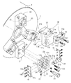
一実施形態を図1乃至図6に基づいて説明する。バックプレート5とハウジング7とを備えるチャック本体1、そのチャック本体1に設けられ軸方向進退可能なドローバ3、そのドローバ3にドローバボルト8を介して接続されるアクチュエータ4、そのアクチュエータ4に係合するジョウアクチュエータ2等の構成は、従来例と同様であるので説明を省略し、以下、把持爪10と、その把持爪10を固定するマスタージョウ12、ストッパ装置40等を中心に説明する。
An embodiment will be described with reference to FIGS. A chuck body 1 having a
図1A及び図1Bに示すように、把持爪10は、そのチャック本体1の中心軸6周りの周方向に沿って、合計3箇所等分方位に設けられている。
As shown in FIGS. 1A and 1B, the gripping
その把持爪10は、前記マスタージョウ12の前面側に固定されるサブジョウ11と、そのサブジョウ11に設けた係止部17に嵌め込まれるプルスタッド(固定軸)13、及びジョウピース15等から構成されている。
The
図2に示すように、ジョウピース15は、前記サブジョウ11に形成された内径側に向く凹状の弧状面10cに面接触する弧状面15cを有している。その両弧状面10c,15cが密着した状態で、ボルト15bが、ジョウピース15のボルト孔15d及びサブジョウ11のボルト孔11aにねじ込まれることにより、ジョウピース15がサブジョウ11に固定される。
As shown in FIG. 2, the
また、そのジョウピース15は、その内径側の先端にワークwの外周に触れる爪部15aが2箇所ずつ取り付けられたワイドジョウ形式となっている。
Further, the
サブジョウ11が固定されるマスタージョウ12は、チャック本体1側のジョウアクチュエータ2に取り付けられている。その取り付けは、マスタージョウ12のボルト孔12e及びジョウアクチュエータ2のボルト孔2aにねじ込まれたボルト12dによって行われる。
The
また、マスタージョウ12は、その前面にフラットな係合端面12aを、及びその内径面に円弧状の係合周面12bを備えている。係合端面12aは、チャック本体1の中心軸6の軸方向に直交する面であり、係合周面12bは、チャック本体1の中心軸6に同心の円弧面となっている。
The
サブジョウ11は、その後面に前記マスタージョウ12の係合端面12aに対向するフラットな係合端面10aを、及び前記マスタージョウ12の係合周面12bに対向する円弧状の係合周面10bを備えている。
The
サブジョウ11が前記マスタージョウ12の前面側に取り付けられる際には、締付手段20によって、サブジョウ11がマスタージョウ12側へ引かれて、サブジョウ11の係合端面10aはマスタージョウ12の係合端面12aにぴったりと圧接(圧力をもって密着)し、また、サブジョウ11の係合周面10bはマスタージョウ12の係合周面12bにぴったりと圧接(圧力をもって密着)し得るようになっている。
When the
その締付手段20の構成は、図2に示すように、前記マスタージョウ12に形成され前記チャック本体1の軸方向に直交する方向に伸びる断面円形のピン孔24と、そのピン孔24内にぴったり嵌るように挿通されるカム軸21と、そのカム軸21の外周面に形成されたカム面21aと、前記把持爪10に形成され前記カム軸21のカム面21aに噛み合うカム当接面13aとを備えている。
As shown in FIG. 2, the tightening means 20 has a
カム軸21は、そのカム軸21の軸方向両側、すなわちカム軸21の先端側及び後端側にそれぞれ断面円形を成す部分を備え、そのカム軸21の軸方向両側における断面円形を成す部分は、それぞれ、前記マスタージョウ12のピン孔24内に隙間なくぴったり嵌るように挿通される。
The
また、そのカム軸21の先端に形成された周方向溝21b内に、マスタージョウ12の外径側からねじ込んだピン22の先端が入り込んでカム軸21が抜け止めされる。また、その周方向溝21b内に平行ピン21cがねじ込まれており、その平行ピン21cにピン22の先端が当たることにより、カム軸21の軸周り回転が規制される。なお、平行ピン21cは、カム軸21の外周面よりも外径側に突出しないようにしている。
Further, the tip of the
また、前記カム軸21の軸方向中ほど、すなわち前記断面円形を成す部分に夾まれた領域が、相対的に小断面となっている。
その小断面の部分は、図3に示すように、軸周りに形成された弧状面とフラット面とからなる断面D字状であり、その弧状面は、前記カム軸21の軸中心pからの距離が反時計回り方向に向かうにつれて徐々に遠ざかるカム面21aとなっている。
Further, the middle of the
As shown in FIG. 3, the small cross-sectional portion has a D-shaped cross section composed of an arcuate surface and a flat surface formed around the axis, and the arcuate surface extends from the axial center p of the
このカム軸21がマスタージョウ12のピン孔24内に挿通された状態で、前記カム面21aは、そのマスタージョウ12に形成されたチャック本体1の軸方向に伸びる固定軸挿通孔25内に臨むことができるようになっている。
In a state where the
また、このカム軸21のカム面21aに噛み合う前記カム当接面13aは、図4(a)(b)に示すように、前記サブジョウ11の前記係止部17に固定される前記プルスタッド(固定軸)13の軸部に形成される。
Further, the
係止部17は、チャック本体1の中心軸6の軸方向と並行に伸びる断面U字形の溝17bと、前記プルスタッド13の頭部を収納する拡径部17aを備え、そのプルスタッド13の頭部の後端面13cが前記係止部17の前端面17cに当接し、また、プルスタッド13の軸部が前記溝17bの底にぴったりと隙間なく挿通されている。
The locking
また、そのプルスタッド13の軸部の先端は、前記固定軸挿通孔25内に入り込んでおり、その状態で、前記軸部に形成されたカム当接面13aが、前記カム軸21のカム面21aに噛み合うようになっている。カム当接面13aは、前記プルスタッド13の軸部の軸方向に伸びる凹状の円弧面となっており、カム面21aは、そのプルスタッド13の凹状の円弧面に対向し、且つそのカム当接面13aに線接触し得る円筒面状となっている(図3参照)。
Further, the tip end of the shaft portion of the
マスタージョウ12とサブジョウ11(把持爪10)とを固定する際における、前記締付手段20の作用について説明すると、マスタージョウ12は、既にジョウアクチュエータ2に固定されている状態とする。また、対象となるワークwの種別に合致する把持爪10を用意し、その把持爪10のジョウピース15は、既にサブジョウ11に取り付けられている状態とする。
The operation of the tightening means 20 in fixing the
まず、その用意した把持爪10のサブジョウ11に、プルスタッド13を嵌め込む。プルスタッド13は、その頭部を前記サブジョウ11に形成された係止部17の拡径部17aに収納し、軸部を前記溝17bに挿通する。
サブジョウ11の係合端面10a及び係合周面10bをそれぞれマスタージョウ12の係合端面12a及び係合周面12bに宛がうとともに、前記溝17bから突出するプルスタッド13の軸部をマスタージョウ12の固定軸挿通孔25内に挿入する。
First, the
The
つぎに、ピン孔24内にカム軸21を挿通させ、そのカム軸21のカム面21aに、前記プルスタッド13のカム当接面13aを対向させる(図4(a)参照)。このとき、プルスタッド13を矢印B方向へ押し込み、サブジョウ11をマスタージョウ12側に引き込んでおく。抜け止め用の前記ピン22は、この際にねじ込んでおいてもよいし、その後ねじ込んでもかまわない。
Next, the
図4(b)に矢印Aで示すように、カム軸21を時計回りに回転させる。カム軸21を回転させることにより、図4(c)に示すカム軸21の回転中心からの径差r1,r2に基づき、カム面21aが前記カム当接面13aに係合し(噛み合い)、その係合により、プルスタッド13を図中の矢印C方向へ押し付ける。
このプルスタッド13は、前記矢印C方向への押し付け力の径方向分力により内径側へ押し付けられるとともに、同時に、その軸方向分力によりやや軸方向後方(矢印B方向)に引かれ、マスタージョウ12の係合端面12aとサブジョウ11の係合端面10a同士が圧力をもって密着した状態に固定される。その密着により、サブジョウ11とマスタージョウ12とがチャック本体1の軸方向に位置決めされるとともに、その位置で、サブジョウ11とマスタージョウ12とが不動に固定される。
As shown by an arrow A in FIG. 4B, the
The
このとき、プルスタッド13の先端にはバネ挿入孔13dを備え、その中にコイルバネ14を収納している。そのコイルバネ14は、ジョウアクチュエータ2の前端面に当接しているので、そのプルスタッド13が前記矢印C方向への押し付け力の軸方向分力により矢印B方向に引かれた際に、その引込み力に対してコイルバネ14の弾性力が対抗して、カム面21aとカム当接面13aとがスムースに係脱するようにしている。なお、コイルバネ14は、他の弾性部材によってもよい。
At this time, a
また、締付手段20が、前記マスタージョウ12の係合端面12aとサブジョウ11の係合端面10a同士が圧力をもって密着させるのと同時に、その締付手段20は、前記サブジョウ11の係合周面10bと前記マスタージョウ12の係合周面12bとを圧力をもって密着させる。このため、そのサブジョウ11とマスタージョウ12とは、チャック本体1の径方向に対して、より高精度で位置決めされることになる。
In addition, the fastening means 20 causes the
なお、サブジョウ11とマスタージョウ12とは、前記カム面21aとカム当接面13aとの係合のみによっても、相互にチャック本体1の径方向に位置決めされ得るが、上記のように、締付手段20により両係合周面10b,12b同士を密着させる構成とすれば、その位置決めの精度を向上し得る。
また、この実施形態のように、前記両係合周面10b,12bをそれぞれ前記中心軸6と同心の円弧面とすることにより、前記径方向への位置決め機能に加え、チャック本体1の中心軸6周りにおける周方向への位置決め機能も高精度である。
The
Further, as in this embodiment, both the engaging
なお、この係合周面10bと係合端面10a、及び係合周面12bと係合端面12aとの成す角度αは、それぞれ互いに直角、あるいは鈍角を成す向きであってもよいが、この実施形態では両者の成す角度αを鋭角としている。すなわち、前記両係合周面10b,12bは円弧面であるので、その両係合周面10b,12bは、前記中心軸6を通るいずれの断面においても、それぞれ前記両係合端面10a,12aに対して同一の角度αを成し、その角度αが鋭角となっている構成である。
このため、前記カム軸21とプルスタッド13とがサブジョウ11をマスタージョウ12側に引込む際に、その鋭角αを夾む両面10a,10b;12a,12b間の挟み込み効果によりその位置ずれを防ぎ、前記両係合端面10a,12aと前記両係合周面10b,12bとをそれぞれしっかりと密着させやすい。
Note that the angles α formed by the engagement
For this reason, when the
また、この角度αを鋭角としたことにより、把持爪10がワークwから軸方向前方への反力を受けた際に、その両係合周面10b,12b同士の密着度合いが増す方向に把持爪10が押圧されることとなる。このため、把持爪10がマスタージョウ12に対して動かないように、すなわち、前記両係合端面10a,12a同士の密着が解除しないように、よりしっかりと対抗し得るようになる。
このような特性は、特に、ワークwを把持する際に、そのワークwをチャック本体1側に対して後方側へ引き込んで掴むタイプの引き込み式チャックの場合は、把持爪10がワークwから軸方向前方への反力を受けやすいので、より有効であるといえる。
In addition, by setting the angle α to an acute angle, when the
In particular, in the case of a retractable chuck of the type in which the workpiece w is pulled backward with respect to the chuck body 1 side when the workpiece w is gripped, the
なお、把持爪10がワークwから軸方向前方への反力を受けた場合において、前記カム軸21には、図4(b)の矢印A方向へ軸周り回転するように力が作用する。この矢印A方向は、そのカム面21aとカム当接面13aとの係合を強める方向であることから、この点においても、前記両係合端面10a,12a同士の密着解除が阻止される機能を有していることとなる。
When the
マスタージョウ12にサブジョウ11を取り付けた後、そのサブジョウ11の両側にサイドプレート16,16を取り付ける。
サイドプレート16,16は、図2に示すように、それぞれビス穴16cを複数備えている。それらのビス穴16cにネジ16a,16bを挿通して、そのネジ16a,16bをそれぞれサブジョウ11に設けたネジ孔11b及びマスタージョウ12に設けたネジ孔12fにねじ込むことにより、前記サブジョウ11と前記マスタージョウ12との固定の強化を図っている。
After the
As shown in FIG. 2, each of the
なお、サブジョウ11(把持爪10)をマスタージョウ12から取り外す際には、上記と逆の手順となるので、その説明を省略する。
It should be noted that when removing the sub jaw 11 (gripping claw 10) from the
つぎに、ストッパ装置40に付いて説明する。ストッパ装置40は、チャック本体1に不動に固定されたベース部30に、ボールプランジャ機構を備えた取付装置35を介して着脱自在に固定される基部41と、その基部41の前端に設けられる環状部44、その環状部44に沿って着脱自在のストッパリング42とを備えている。
ストッパリング42は、基部41に設けたボルト孔41aにボルト43をねじ込むことにより、その基部41と一体に固定される。
Next, the
The
ベース部30は、図2に示すように、チャック本体1の中心軸6周りに隣り合う把持爪10,10の間に、それぞれ合計3箇所の取付装置35を備えている。この実施形態では、取付装置35として、コスメック社製「データムクランプ(商品名)」を使用している。
As shown in FIG. 2, the
取付装置35は、ベース部30に形成された円筒状の凹部33内に嵌るピストンロッド39と、そのピストンロッド39の前方側に配置されベース部30の前面に当接する本体部38、そのピストンロッド39と本体部38との間に配置されるクランプバネ39a、及び、本体部38に設けられるボールプラジャ36等から構成される。
The
また、そのベース部30は、前記取付装置35を収納した凹部33内に通じる油圧回路31を備え、油圧回路31はチャック本体1のドローバ3等に設けた油路を通じて図示しない油圧供給源に通じている。
また、ベース部30は、本体部38の前面に開口して設けた開口部37a、及びその側面に開口して設けた開口部37bに通じるエア通路37を備え、そのエア通路37はチャック本体1のドローバ3等に設けた通路を通じて図示しない気体供給源に通じている。
Further, the
Further, the
ストッパ装置40の着脱について説明する。ストッパ装置40のストッパリング42は、把持する対象となるワークwに対応したものが用意されている。
チャック本体1の前面にストッパ装置40を宛がい、ベース部30の各取付装置35を、ストッパ装置40の後面に設けた凹部45内にそれぞれ収納させる。このとき、基部41のピン孔41bに嵌るピン32が、ベース部30に設けたガイド孔に嵌るので、両者の位置合わせが容易となっている。
The attachment / detachment of the
The
また、このとき、気体供給源からエア通路37を通じて気体が供給され、その気体が、前記本体部38の前面の開口部37a及び側面の開口部37bから噴出されて、その凹部45周辺のエアブローによる清掃が自動的に行われる。
At this time, gas is supplied from the gas supply source through the
凹部45内に嵌め込んでストッパ装置40に一体に固定された環状のブロック34が、前記本体部38の前端の外周に嵌り込まれる。このとき、そのブロック34の内周テーパ面34dが、本体部38の外周に設けたテーパスリーブのテーパ面38cに摺れながら嵌め込まれていき、最後にブロック34の後面34aが、本体部38の前面38aに当接してストッパ装置40がチャック本体1に対して位置決めされる。
なお、この過程で、前記油圧回路31内の油圧はロックされた状態であり、前記ピストンロッド39は凹部33内で後方に向かって押し込むことができない状態である。また、前記エアブローは、前記後面34aと前面38aとが密着するまでの間、その後面34aと前面38aとの間の隙間に継続して作用しているが、凹部45の底部にも継続して作用している。
An
In this process, the hydraulic pressure in the
前記ブロック34の後面34aと、本体部38の前面38aとが密着すると、それとともに、ブロック34の突出部34cが、ボールプランジャ36のボールに噛み込んで、そのボールを凹部38bから前方へ離脱させる。
When the
さらに、前記油圧回路31内の油圧をリリースすると、本体部38のクランプバネ39aの弾性力によりピストンロッド39が後方側(図6に示す左側)に押し下げられ、ボールプランジャ36のボールは、前記本体部の突起38cとの間にさらに強く噛み込んだ状態となって、ストッパ装置40は、ベース部30から離れないように抜け止めされた状態となる。
Further, when the hydraulic pressure in the
なお、ストッパ装置40を取り外す際には、上記と逆の手順となるので、その説明を省略する。
In addition, when removing the
この実施形態では、把持爪10及び前記ストッパ装置40用の取付装置35は、それぞれチャック本体1の中心軸6の周囲に3箇所、周方向に沿って交互に放射状に設けられているが、把持爪10及び前記ストッパ装置40用の取付装置35の数及び配置は任意に設定できる。
In this embodiment, the gripping
また、ストッパ装置40をチャック本体1に着脱自在とする取付装置35の構成としては、他の構成を採用してもよい。その取付装置35としては、少なくとも前記チャック本体1とストッパ装置40との軸方向の位置決め機能と、その位置決めされた状態における前記ボールプランジャ機構による抜け止め機能とを備えていればよく、したがって、上記実施形態における油圧回路31、油圧供給源、エア通路37、気体供給源等は、必要に応じて省略し得るものである。
Further, as the configuration of the mounting
1 チャック本体
2 揺動部材(ジョウアクチュエータ)
3 ドローバ
4 駆動部材(アクチュエータ)
4a フランジ部
5 バックプレート
6 中心軸(チャック本体の中心軸)
7 ハウジング
8 ドローバボルト
10 把持爪
10a、12a 係合端面
10b、12b 係合周面
11 サブジョウ
12 マスタージョウ
13 固定軸(プルスタッド)
13a カム当接面
14 弾性部材(コイルバネ)
15 ジョウピース
16 サイドプレート
17 係止部
20 締付手段
21 カム軸
21a カム面
24 ピン孔
25 固定軸挿通孔
30 ベース部
31 油圧回路
35 取付装置
36 ボールプランジャ
37 エア通路
40 ストッパ装置
w ワーク
1 Chuck
3
7
13a
15
Claims (6)
前記チャック本体1の前面に径方向に移動自在のマスタージョウ12を設け、前記各把持爪10は、締付手段20によって前記マスタージョウ12に着脱自在に取り付けられてそのマスタージョウ12とともに径方向へ移動するようになっており、
前記各把持爪10と前記マスタージョウ12とは前記取り付け状態で相互に前記チャック本体1の軸方向に向かい合う係合端面10a,12aをそれぞれ備え、前記締付手段20は、前記マスタージョウ12に形成され前記チャック本体1の軸方向及び半径方向に直交する方向に伸びるピン孔24と、そのピン孔24内にぴったり嵌るように挿通されるカム軸21と、そのカム軸21の外周面に形成されたカム面21aと、前記把持爪10に形成され前記カム軸21のカム面21aに噛み合うカム当接面13aとを備え、前記カム軸21をそのカム軸21の軸周りに回転させることにより前記カム面21aと前記カム当接面13aとが係脱し、その係脱による前記両係合端面10a,12a同士の密着及び密着解除により前記各把持爪10と前記マスタージョウ12とが着脱自在であるとともに、前記各把持爪10と前記マスタージョウ12とは、前記両係合端面10a,12a同士の密着により前記チャック本体1の軸方向に位置決めされ且つ前記カム面21aと前記カム当接面13aとの係合により前記チャック本体1の径方向に位置決めされ、
前記把持爪10は、前記係合端面10aを備えるサブジョウ11と、そのサブジョウ11に設けられ前記チャック本体1の軸方向に伸びる固定軸13とを備え、前記固定軸13は前記サブジョウ11に形成された係止部17に固定されるようになっており、前記カム当接面13aは前記固定軸13に形成されて、前記カム軸21は前記固定軸13を挟んで前記チャック本体1の軸方向に直交する方向の両側で前記マスタージョウ12に支持されていることを特徴とするチャック装置。 A plurality of gripping claws 10 are provided around the central axis 6 of the chuck body 1, and each gripping claw 10 is moved in the radial direction of the chuck body 1, whereby the workpiece w is concentric with the central axis 6 by the gripping claws 10. In the chuck device to grip
A master jaw 12 that is movable in the radial direction is provided on the front surface of the chuck body 1, and each of the gripping claws 10 is detachably attached to the master jaw 12 by a fastening means 20, and along with the master jaw 12 in the radial direction. It is supposed to move,
The gripping claws 10 and the master jaw 12 are respectively provided with engagement end faces 10 a and 12 a that face each other in the axial direction of the chuck body 1 in the attached state, and the fastening means 20 is formed on the master jaw 12. A pin hole 24 extending in a direction perpendicular to the axial direction and the radial direction of the chuck body 1, a cam shaft 21 inserted so as to fit in the pin hole 24, and an outer peripheral surface of the cam shaft 21 are formed. A cam contact surface 13a formed on the gripping claw 10 and meshing with the cam surface 21a of the camshaft 21. The camshaft 21 is rotated by rotating the camshaft 21 around the camshaft 21. The cam surface 21a and the cam abutment surface 13a are engaged and disengaged, and the engaging claws 10a and 12a are brought into close contact with each other and released from the close contact with the gripping claws 10a. The master jaw 12 is detachable, and the gripping claws 10 and the master jaw 12 are positioned in the axial direction of the chuck body 1 by the close contact between the engagement end faces 10a and 12a, and the cam. Positioned in the radial direction of the chuck body 1 by the engagement of the surface 21a and the cam contact surface 13a ,
The gripping claw 10 includes a sub jaw 11 having the engagement end face 10 a and a fixed shaft 13 provided on the sub jaw 11 and extending in the axial direction of the chuck body 1, and the fixed shaft 13 is formed on the sub jaw 11. The cam contact surface 13 a is formed on the fixed shaft 13, and the cam shaft 21 extends in the axial direction of the chuck body 1 with the fixed shaft 13 interposed therebetween. The chuck device is supported by the master jaw 12 on both sides in a direction perpendicular to the chuck.
Priority Applications (1)
| Application Number | Priority Date | Filing Date | Title |
|---|---|---|---|
| JP2007153774A JP5204992B2 (en) | 2007-06-11 | 2007-06-11 | Chuck device |
Applications Claiming Priority (1)
| Application Number | Priority Date | Filing Date | Title |
|---|---|---|---|
| JP2007153774A JP5204992B2 (en) | 2007-06-11 | 2007-06-11 | Chuck device |
Publications (2)
| Publication Number | Publication Date |
|---|---|
| JP2008302484A JP2008302484A (en) | 2008-12-18 |
| JP5204992B2 true JP5204992B2 (en) | 2013-06-05 |
Family
ID=40231632
Family Applications (1)
| Application Number | Title | Priority Date | Filing Date |
|---|---|---|---|
| JP2007153774A Active JP5204992B2 (en) | 2007-06-11 | 2007-06-11 | Chuck device |
Country Status (1)
| Country | Link |
|---|---|
| JP (1) | JP5204992B2 (en) |
Families Citing this family (7)
| Publication number | Priority date | Publication date | Assignee | Title |
|---|---|---|---|---|
| JP4720899B2 (en) | 2008-11-27 | 2011-07-13 | ソニー株式会社 | COMMUNICATION DEVICE, COMMUNICATION METHOD, PROGRAM, AND COMMUNICATION SYSTEM |
| JP2010158751A (en) * | 2009-01-09 | 2010-07-22 | Amada Co Ltd | Sawing machine |
| JP5769495B2 (en) * | 2011-05-23 | 2015-08-26 | 帝国チャック株式会社 | Stopper mounting structure of chuck device |
| CN106240900B (en) * | 2016-08-29 | 2018-09-11 | 如皋市包装食品机械有限公司 | A kind of rotary type multi-station Jia Tang mechanisms |
| KR102282818B1 (en) * | 2017-06-20 | 2021-07-27 | 가부시키가이샤 코스멕 | gripping device |
| CN110480043B (en) * | 2019-08-20 | 2024-06-18 | 浙江万里扬新能源驱动科技有限公司 | Clamp for machining annular workpiece |
| CN112719327B (en) * | 2020-12-10 | 2024-06-07 | 黄锐 | Chuck |
Family Cites Families (5)
| Publication number | Priority date | Publication date | Assignee | Title |
|---|---|---|---|---|
| FR2584960B1 (en) * | 1985-07-17 | 1987-10-02 | Sandvik Tobler | CLAMPING CHANGE SYSTEM ON A MACHINE TOOL |
| JPH02232107A (en) * | 1989-03-01 | 1990-09-14 | Utsunomiya Kogu Seisakusho:Kk | Removing device for chuck jaw |
| JP2740938B2 (en) * | 1994-07-01 | 1998-04-15 | 合資会社日下歯車製作所 | Outer diameter collet chuck |
| JP3653645B2 (en) * | 1995-09-30 | 2005-06-02 | 株式会社北川鉄工所 | Front replaceable finger chuck |
| JP2004255484A (en) * | 2003-02-25 | 2004-09-16 | Pascal Engineering Corp | Clamping apparatus |
-
2007
- 2007-06-11 JP JP2007153774A patent/JP5204992B2/en active Active
Also Published As
| Publication number | Publication date |
|---|---|
| JP2008302484A (en) | 2008-12-18 |
Similar Documents
| Publication | Publication Date | Title |
|---|---|---|
| JP5204992B2 (en) | Chuck device | |
| WO2005000530A1 (en) | Bit holder device | |
| JPH02503768A (en) | Device that clamps the tool holder shaft | |
| JP2006326831A (en) | Clamp structure for tool with handle | |
| US7249770B2 (en) | Locking drill chuck | |
| JP5279411B2 (en) | Work positioning device | |
| JP4972362B2 (en) | Diaphragm chuck | |
| US7556269B2 (en) | Tool-carrier chuck for rotating machine, furnished with locking means | |
| JP2662018B2 (en) | Attachment attachment / detachment device | |
| JP4544969B2 (en) | Fastening device | |
| US11660682B2 (en) | Chuck with locking clutch | |
| JP2008532785A (en) | Tool holding chuck for loading rotating machines | |
| JPH02172605A (en) | Fastener | |
| TW201900303A (en) | Fixture mechanism | |
| JP2006346780A (en) | Chuck for machine tool | |
| JP2012218117A (en) | Holding claw mounting structure of chuck device | |
| JP7308528B2 (en) | Chuck device | |
| JP2009050973A (en) | Chuck | |
| JP5766502B2 (en) | Fastening device | |
| JP2000218414A (en) | Collet chuck joint device | |
| JP2000079507A (en) | Disassembling tool for fastening member | |
| JP3691957B2 (en) | Clamping device, fixing device and valve seat machining tool device | |
| JP2011240442A (en) | Stop ring attaching and detaching tool | |
| JP4564727B2 (en) | Automatic tool holder attachment / detachment method, tool holder automatic attachment / detachment system, and tool storage device | |
| JP2553535Y2 (en) | Broaching machine pull head |
Legal Events
| Date | Code | Title | Description |
|---|---|---|---|
| A621 | Written request for application examination |
Free format text: JAPANESE INTERMEDIATE CODE: A621 Effective date: 20100608 |
|
| A977 | Report on retrieval |
Free format text: JAPANESE INTERMEDIATE CODE: A971007 Effective date: 20120315 |
|
| A131 | Notification of reasons for refusal |
Free format text: JAPANESE INTERMEDIATE CODE: A131 Effective date: 20120529 |
|
| A521 | Request for written amendment filed |
Free format text: JAPANESE INTERMEDIATE CODE: A523 Effective date: 20120730 |
|
| TRDD | Decision of grant or rejection written | ||
| A01 | Written decision to grant a patent or to grant a registration (utility model) |
Free format text: JAPANESE INTERMEDIATE CODE: A01 Effective date: 20130205 |
|
| A61 | First payment of annual fees (during grant procedure) |
Free format text: JAPANESE INTERMEDIATE CODE: A61 Effective date: 20130218 |
|
| R150 | Certificate of patent or registration of utility model |
Ref document number: 5204992 Country of ref document: JP Free format text: JAPANESE INTERMEDIATE CODE: R150 Free format text: JAPANESE INTERMEDIATE CODE: R150 |
|
| FPAY | Renewal fee payment (event date is renewal date of database) |
Free format text: PAYMENT UNTIL: 20160222 Year of fee payment: 3 |
|
| R250 | Receipt of annual fees |
Free format text: JAPANESE INTERMEDIATE CODE: R250 |
|
| R250 | Receipt of annual fees |
Free format text: JAPANESE INTERMEDIATE CODE: R250 |
|
| R250 | Receipt of annual fees |
Free format text: JAPANESE INTERMEDIATE CODE: R250 |
|
| R250 | Receipt of annual fees |
Free format text: JAPANESE INTERMEDIATE CODE: R250 |
|
| R250 | Receipt of annual fees |
Free format text: JAPANESE INTERMEDIATE CODE: R250 |
|
| R250 | Receipt of annual fees |
Free format text: JAPANESE INTERMEDIATE CODE: R250 |
|
| R250 | Receipt of annual fees |
Free format text: JAPANESE INTERMEDIATE CODE: R250 |
|
| R250 | Receipt of annual fees |
Free format text: JAPANESE INTERMEDIATE CODE: R250 |
|
| R250 | Receipt of annual fees |
Free format text: JAPANESE INTERMEDIATE CODE: R250 |