WO2019030975A1 - 医用画像診断装置、及び画像処理方法 - Google Patents
医用画像診断装置、及び画像処理方法 Download PDFInfo
- Publication number
- WO2019030975A1 WO2019030975A1 PCT/JP2018/014588 JP2018014588W WO2019030975A1 WO 2019030975 A1 WO2019030975 A1 WO 2019030975A1 JP 2018014588 W JP2018014588 W JP 2018014588W WO 2019030975 A1 WO2019030975 A1 WO 2019030975A1
- Authority
- WO
- WIPO (PCT)
- Prior art keywords
- range
- scan range
- medical image
- scan
- subject
- Prior art date
- Legal status (The legal status is an assumption and is not a legal conclusion. Google has not performed a legal analysis and makes no representation as to the accuracy of the status listed.)
- Ceased
Links
Images


Classifications
-
- A—HUMAN NECESSITIES
- A61—MEDICAL OR VETERINARY SCIENCE; HYGIENE
- A61B—DIAGNOSIS; SURGERY; IDENTIFICATION
- A61B6/00—Apparatus or devices for radiation diagnosis; Apparatus or devices for radiation diagnosis combined with radiation therapy equipment
- A61B6/02—Arrangements for diagnosis sequentially in different planes; Stereoscopic radiation diagnosis
- A61B6/03—Computed tomography [CT]
- A61B6/032—Transmission computed tomography [CT]
-
- A—HUMAN NECESSITIES
- A61—MEDICAL OR VETERINARY SCIENCE; HYGIENE
- A61B—DIAGNOSIS; SURGERY; IDENTIFICATION
- A61B6/00—Apparatus or devices for radiation diagnosis; Apparatus or devices for radiation diagnosis combined with radiation therapy equipment
- A61B6/40—Arrangements for generating radiation specially adapted for radiation diagnosis
-
- A—HUMAN NECESSITIES
- A61—MEDICAL OR VETERINARY SCIENCE; HYGIENE
- A61B—DIAGNOSIS; SURGERY; IDENTIFICATION
- A61B6/00—Apparatus or devices for radiation diagnosis; Apparatus or devices for radiation diagnosis combined with radiation therapy equipment
- A61B6/42—Arrangements for detecting radiation specially adapted for radiation diagnosis
-
- A—HUMAN NECESSITIES
- A61—MEDICAL OR VETERINARY SCIENCE; HYGIENE
- A61B—DIAGNOSIS; SURGERY; IDENTIFICATION
- A61B6/00—Apparatus or devices for radiation diagnosis; Apparatus or devices for radiation diagnosis combined with radiation therapy equipment
- A61B6/46—Arrangements for interfacing with the operator or the patient
- A61B6/461—Displaying means of special interest
- A61B6/465—Displaying means of special interest adapted to display user selection data, e.g. graphical user interface, icons or menus
-
- A—HUMAN NECESSITIES
- A61—MEDICAL OR VETERINARY SCIENCE; HYGIENE
- A61B—DIAGNOSIS; SURGERY; IDENTIFICATION
- A61B6/00—Apparatus or devices for radiation diagnosis; Apparatus or devices for radiation diagnosis combined with radiation therapy equipment
- A61B6/46—Arrangements for interfacing with the operator or the patient
- A61B6/467—Arrangements for interfacing with the operator or the patient characterised by special input means
-
- A—HUMAN NECESSITIES
- A61—MEDICAL OR VETERINARY SCIENCE; HYGIENE
- A61B—DIAGNOSIS; SURGERY; IDENTIFICATION
- A61B6/00—Apparatus or devices for radiation diagnosis; Apparatus or devices for radiation diagnosis combined with radiation therapy equipment
- A61B6/50—Apparatus or devices for radiation diagnosis; Apparatus or devices for radiation diagnosis combined with radiation therapy equipment specially adapted for specific body parts; specially adapted for specific clinical applications
- A61B6/503—Apparatus or devices for radiation diagnosis; Apparatus or devices for radiation diagnosis combined with radiation therapy equipment specially adapted for specific body parts; specially adapted for specific clinical applications for diagnosis of the heart
-
- A—HUMAN NECESSITIES
- A61—MEDICAL OR VETERINARY SCIENCE; HYGIENE
- A61B—DIAGNOSIS; SURGERY; IDENTIFICATION
- A61B6/00—Apparatus or devices for radiation diagnosis; Apparatus or devices for radiation diagnosis combined with radiation therapy equipment
- A61B6/54—Control of apparatus or devices for radiation diagnosis
- A61B6/545—Control of apparatus or devices for radiation diagnosis involving automatic set-up of acquisition parameters
-
- A—HUMAN NECESSITIES
- A61—MEDICAL OR VETERINARY SCIENCE; HYGIENE
- A61B—DIAGNOSIS; SURGERY; IDENTIFICATION
- A61B6/00—Apparatus or devices for radiation diagnosis; Apparatus or devices for radiation diagnosis combined with radiation therapy equipment
- A61B6/04—Positioning of patients; Tiltable beds or the like
- A61B6/0407—Supports, e.g. tables or beds, for the body or parts of the body
-
- A—HUMAN NECESSITIES
- A61—MEDICAL OR VETERINARY SCIENCE; HYGIENE
- A61B—DIAGNOSIS; SURGERY; IDENTIFICATION
- A61B6/00—Apparatus or devices for radiation diagnosis; Apparatus or devices for radiation diagnosis combined with radiation therapy equipment
- A61B6/44—Constructional features of apparatus for radiation diagnosis
- A61B6/4429—Constructional features of apparatus for radiation diagnosis related to the mounting of source units and detector units
- A61B6/4435—Constructional features of apparatus for radiation diagnosis related to the mounting of source units and detector units the source unit and the detector unit being coupled by a rigid structure
-
- A—HUMAN NECESSITIES
- A61—MEDICAL OR VETERINARY SCIENCE; HYGIENE
- A61B—DIAGNOSIS; SURGERY; IDENTIFICATION
- A61B6/00—Apparatus or devices for radiation diagnosis; Apparatus or devices for radiation diagnosis combined with radiation therapy equipment
- A61B6/46—Arrangements for interfacing with the operator or the patient
- A61B6/467—Arrangements for interfacing with the operator or the patient characterised by special input means
- A61B6/469—Arrangements for interfacing with the operator or the patient characterised by special input means for selecting a region of interest [ROI]
-
- A—HUMAN NECESSITIES
- A61—MEDICAL OR VETERINARY SCIENCE; HYGIENE
- A61B—DIAGNOSIS; SURGERY; IDENTIFICATION
- A61B6/00—Apparatus or devices for radiation diagnosis; Apparatus or devices for radiation diagnosis combined with radiation therapy equipment
- A61B6/54—Control of apparatus or devices for radiation diagnosis
- A61B6/541—Control of apparatus or devices for radiation diagnosis involving acquisition triggered by a physiological signal
-
- A—HUMAN NECESSITIES
- A61—MEDICAL OR VETERINARY SCIENCE; HYGIENE
- A61B—DIAGNOSIS; SURGERY; IDENTIFICATION
- A61B6/00—Apparatus or devices for radiation diagnosis; Apparatus or devices for radiation diagnosis combined with radiation therapy equipment
- A61B6/54—Control of apparatus or devices for radiation diagnosis
- A61B6/542—Control of apparatus or devices for radiation diagnosis involving control of exposure
- A61B6/544—Control of apparatus or devices for radiation diagnosis involving control of exposure dependent on patient size
Definitions
- the present invention relates to a medical image diagnostic apparatus, and more particularly to a technique for setting an X-ray irradiation range and an image creation range in main imaging using a positioning image acquired before main imaging.
- Medical image diagnostic apparatuses are indispensable in current medical care, and one of them is an X-ray CT (Computed Tomography) apparatus.
- An X-ray CT apparatus rotates an X-ray source for irradiating an X-ray to a subject and an X-ray detector for detecting an X-ray dose transmitted through the subject as projection data around the subject.
- the tomographic image of the subject is reconstructed using projection data from a plurality of angles obtained by the above-mentioned method, and the reconstructed tomographic image is displayed.
- the image displayed by the X-ray CT apparatus describes the shape of an organ in a subject and is used for medical image diagnosis.
- Other medical image diagnostic apparatuses include an MRI (Magnetic Resonance Imaging) apparatus and the like. In the present specification, an X-ray CT apparatus will be described as an example.
- the X-ray CT apparatus In the X-ray CT apparatus, generally, before performing the main imaging, imaging of a positioning image for the main imaging plan to the subject is performed. The operator sets an X-ray irradiation range and an image formation range in main imaging by operating a line or the like on the positioning image, and sets various imaging parameters. In the present specification, two of the X-ray irradiation range and the image formation range are collectively referred to as a scan range.
- the medical image diagnostic apparatus of each manufacturer is equipped with a mechanism capable of setting beforehand the imaging conditions recommended by the guidelines or the like as a protocol before the examination, and most of the imaging conditions do not have to be changed at the time of the examination.
- Patent Document 1 the X-ray irradiation range set at the time of the main imaging planning is automatically set in order to improve the time-consuming and inaccuracies of the scan range setting manually performed by the operator. That is being tried.
- the feature amount is extracted from the positioning image and the range extracted using the feature amount is set as the scan range, but the criteria for setting the scan range for each hospital or operator are slightly different . Therefore, in the method of setting the scan range on the basis of uniform criteria, the operator is not set to the scan range that the operator originally wants to set, and eventually the operator has to manually manipulate the scan range, which is the initial purpose of the inspection The operator's scan range setting is less effective in improving the effort and inaccuracies.
- An object of the present invention is to provide a medical image diagnostic apparatus and an image processing method which can cope with setting criteria of a scan range different for each hospital and operator and can improve the time and inaccuracy of the operator at the time of scan range setting. It is to do.
- the present invention is a medical image diagnostic apparatus, and a storage unit that stores a range setting pattern in which an inspection object is associated with a margin value, and an inspection protocol, and a subject And a scan range automatic setting unit configured to automatically set a scan range at the time of examination in accordance with the range setting pattern associated with the examination protocol after taking a positioning image obtained by photographing the subject. .
- the present invention is an image processing method of a medical image diagnostic apparatus having a storage unit and a control unit, and a range setting pattern in which an inspection object and a margin value are associated with each other in the storage unit.
- the examination protocol are linked and stored, and the control unit takes a positioning image obtained by photographing the subject and then scans the scan range at the time of examination according to the range setting pattern associated with the examination protocol.
- the present invention provides an image processing method configured to automatically set
- the present invention it is possible to cope with the setting reference of the scan range which is different for each hospital and operator, and to improve the time and inaccuracy of the operator when setting the scan range.
- FIG. 6 is a diagram showing a process flow for setting a scan range according to the first embodiment.
- FIG. 7 is a diagram showing an example of a range setting pattern creation screen in which an inspection target and a margin value are associated with each other according to the first embodiment. It is a figure for demonstrating the influence by the individual difference of a subject based on Example 1.
- FIG. FIG. 7 is a diagram showing an example of a margin value map according to the first embodiment.
- FIG. 6 is a diagram for explaining generation of an extraction region range according to the first embodiment. It is a figure for demonstrating the difference of the irradiation X-ray maximum width by the height of a bed based on Example 2.
- FIG. It is a figure which shows the example of the map which matched the height of the bed, and the magnification of the to-be-examined person in an image based on Example 2.
- FIG. FIG. 8 is a diagram showing a process flow for setting a scan range according to a second embodiment.
- FIG. 16 is a diagram showing an example in which an electrocardiogram waveform and a heart size are associated according to a third embodiment.
- FIG. 18 is a diagram illustrating a processing flow for setting a scan range according to a third embodiment.
- FIG. 21 is a diagram for explaining a scan range calculation method in the case where a body axis of a subject is inclined according to a fourth embodiment. It is a following figure for demonstrating the scan range calculation method when the body axis
- FIG. FIG. 21 is a diagram for explaining a scan range calculation method in the case where a body axis of a subject is inclined according to a fourth embodiment. It is a following figure for demonstrating the scan range calculation method when the body axis
- FIG. 18 is a diagram illustrating a process flow for setting a scan range according to a fourth embodiment.
- FIG. 18 is a diagram for explaining the size of the collected FOV and the subject according to the fifth embodiment.
- FIG. 18 is a diagram for explaining the relationship between the acquisition FOV and the beam hardening correction according to the fifth embodiment.
- FIG. 18 is a diagram illustrating a process flow for setting a scan range according to a fifth embodiment.
- FIG. 18 is a diagram illustrating a pre-processing flow for scan range setting according to a sixth embodiment.
- FIG. 18 is a diagram illustrating a process flow for setting a scan range according to a sixth embodiment.
- the scan range 202 which is automatically set may not coincide with the scan range 203 which the operator originally wants to set.
- feature amounts are extracted from the positioning image 201, and a range based on the extracted feature amounts is set as a scan range 202.
- the criteria for setting the scan range for each hospital or operator are slightly different.
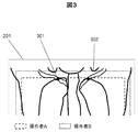
- FIG. 3 shows the difference in the reference for setting the position on the head side of the scan range when the lung field is imaged for the same examination purpose.
- the operator A uses "the intersection 301 between the clavicle and the ribs" as a guide
- the operator B uses "a shoulder recess 302 formed between the raised arm and the head” as a guide.
- the operator does not set the scan range that the operator originally wants to set, and eventually the operator needs to manually adjust the scan range. It is less effective in improving the time and inaccuracies in setting the scan range of the operator, which is the original purpose.
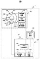
- the X-ray CT apparatus 1 comprises a scan gantry unit 100 and a console 120.
- the scan gantry unit 100 includes an X-ray tube 101, a rotating disk 102, a collimator 103, an X-ray detector 106, a data acquisition device 107, a bed 105, a gantry control device 108, and a bed control device 109. And an X-ray controller 110.
- the X-ray tube 101 is an apparatus for irradiating a subject placed on the bed 105 with X-rays.
- the collimator 103 is a device that limits the radiation range of X-rays emitted from the X-ray tube 101.
- the rotary disk 102 is provided with an opening 104 for receiving the subject placed on the bed 105, and is mounted with the X-ray tube 101 and the X-ray detector 106, and rotates around the subject. .
- the X-ray detector 106 is a device arranged to face the X-ray tube 101 and measure the spatial distribution of the transmitted X-rays by detecting the X-rays transmitted through the subject.
- the data acquisition device 107 is a device that acquires the X-ray dose detected by the X-ray detector 106 as digital data.
- the gantry control device 108 is a device that controls the rotation of the rotating disk 102.
- the bed control device 109 is a device that controls the up and down movement of the bed 105.
- the X-ray controller 110 is a device that controls the power input to the X-ray tube 101.
- the console 120 includes an input device 121, an image calculation device 122, a display device 125, a storage device 123, and a system control device 124.
- a console 120 can be realized by a personal computer (PC), a server or the like provided with a normal computer configuration.
- the input device 121 is a device for inputting an examinee's name, examination date and time, imaging conditions and the like, and more specifically, is a keyboard or a pointing device.
- the image calculation unit 122 is a unit that calculates and processes measurement data sent from the data acquisition unit 107 to reconstruct a CT image.
- the display device 125 is a device that displays the CT image created by the image processing device 122, and specifically, is a CRT (Cathode-Ray Tube), a liquid crystal display, or the like.
- the storage device 123 is a device that stores data collected by the data collection device 107 and image data of a CT image created by the image calculation device 122, and is specifically an HDD (Hard Disk Drive) or the like.
- the system control device 124 is a control unit of the entire device that controls these devices and the gantry control device 108, the bed control device 109, and the X-ray control device 110.
- the X-ray control device 110 controls the power input to the X-ray tube 101 based on imaging conditions such as a scan range input from the input device 121, in particular, X-ray tube voltage, X-ray tube current, etc.
- the tube 101 irradiates the subject with X-rays according to the imaging conditions.
- the X-ray detector 106 detects X-rays emitted from the X-ray tube 101 and transmitted through the subject with a number of X-ray detection elements, and measures the distribution of the transmitted X-rays.
- the rotating disk 102 is controlled by the gantry controller 108, and rotates based on the imaging conditions, particularly the rotational speed, input from the input device 121.
- the bed 105 is controlled by the bed control device 109, and operates based on the imaging conditions input from the input device 121, in particular, the helical pitch and the like.
- the X-ray irradiation from the X-ray tube 101 and the measurement of the transmitted X-ray distribution by the X-ray detector 106 are repeated along with the rotation of the rotating disk 102 to acquire projection data from various angles.
- the acquired projection data from various angles is transmitted to the image processing unit 122.
- the image processing unit 122 reconstructs a CT image by back-projecting the projection data transmitted from various angles.
- the CT image obtained by the reconstruction is displayed on the display device 125.
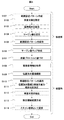
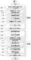
- the X-ray CT apparatus that executes this flowchart associates a range setting pattern in which the inspection target is associated with the margin value with the inspection protocol, stores the storage unit, and acquires a positioning image obtained by imaging the subject. After imaging, a scan range automatic setting unit that automatically sets a scan range at the time of inspection according to the range setting pattern linked to the inspection protocol is provided.
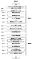
- the scan range setting flow is divided into before inspection (S101 to S107) and at inspection (S108 to S114).
- the main processing of this flowchart is the operator, the image processing unit 122, the system control unit 124, etc., and the processing is executed by the program execution of the central processing unit (CPU) of the PC constituting the image processing unit 122 or the system control unit 124. Is done.
- the inspection target specified by the operator is extracted from the positioning image, an extraction area range including the inspection target is generated, and the operator uses the GUI to obtain an arbitrary width for this extraction area range.
- a range setting pattern in which the determined margin values are associated is generated, and an automatic setting process of a scan range at the time of inspection by the scan range automatic setting unit that links the generated range setting pattern to the inspection protocol is realized. That is, the scan range automatic setting unit controls the display device 125 as the display unit to display the positioning image and the range setting pattern based on the margin value input from the input unit. Furthermore, as will be described later, the scan range automatic setting unit controls the display unit to display a list of range setting patterns stored in the storage unit.
- Step S101 Range Setting Pattern Creation
- the operator creates a range setting pattern in the pre-inspection flow.
- the range setting pattern indicates a range set as a scan range at the time of inspection as will be described later.
- the range setting pattern is preferably set by the operator on the GUI. For example, it is created on the range setting pattern creation screen 501 of FIG. 5 which is an example of the GUI.
- a positioning image 503 on the creation screen As shown on the lower right side of FIG. 5, a positioning image 503 on the creation screen, a line indicating the position of the extraction area range 504 on the positioning image 503, a range 505 obtained by combining the extraction area range and the margin value serving as a range setting pattern. Display a line indicating the position of.
- the positioning image 503 displayed on the screen may be, for example, an image of a human phantom that imitates the anatomical structure of a human body, or may be a positioning image of a subject acquired when the examination was performed in the past.
- a line indicating the position of the extraction area range 504 is extracted by applying an arbitrary extraction algorithm to the positioning image 503.
- the method of extraction may be a known method.
- the operator designates the pattern name of the range setting pattern, the inspection target, the application location, the margin value and the like by the range setting pattern detail setting unit 502.
- the main steps S102 to S105 involved in the creation of the range setting pattern will be described in detail below.
- Step S102 Designation of Examination Target
- the operator designates a pattern name such as “lung field A” set arbitrarily, and designates the examination target of the range setting pattern by an arbitrary method.
- a method may be used in which a part name and the position of the body are associated in advance and designated as "lung field” or the like, or a method of designating an arbitrary part on a human body imitation drawing.
- the positioning image of the whole body may always be displayed.
- a plurality of inspection targets may be specified for one range setting pattern.
- Step S103 Setting an Application Part
- the operator sets whether or not to apply automatic setting for each item for determining a scan range (hereinafter, range parameter).
- the range parameter is, for example, the position on the head side, the position on the foot side, the FOV (Field of View), the FOV center, etc. shown on the lower left side of FIG.
- the range setting pattern detail setting unit 502 is used to set application / non-application (ON / OFF) of automatic setting.
- medical image diagnosis there is a case where the deterioration of the image reading efficiency is prevented by fixing only the FOV to a designated value when comparing the image with the past photographed image.
- the configuration of this embodiment can cope with such a case, and the versatility is enhanced.
- the range parameter set to “Apply (represented as ON in FIG. 5)” for the value applied at the time of inspection the combined value of the extraction area range and the margin value is applied as the imaging condition and reflected in the range setting pattern Ru.
- the range parameter set to "not applied (represented as OFF in FIG. 5)" for example, a form for setting a default value is prepared on the range setting pattern creation screen of FIG. 5 and a value input there is used Alternatively, the inspection protocol may be registered in advance, and the set value may be used.
- Step S104 Designate Margin Value
- the operator designates a margin value for each range parameter with respect to the position of the extraction area range.
- This margin value is the value of the margin in the range 505 set as the scan range at the time of inspection.
- the margin value may be designated by numerical input using the range setting pattern detail setting unit 502 as shown in FIG. 5, for example, or designated by operating the line indicating the range 505 displayed on the positioning image with the mouse You may.
- the unit of the margin value may be a unit of the shooting position (such as millimeter), or may be the number of pixels on the image.
- Step S105 Save Range Setting Pattern
- the range setting pattern in which the extraction area range created with the content specified by the operator is associated with the margin value is saved in the storage unit such as the storage device 123.
- a plurality of range setting patterns stored and accumulated in the storage unit may be displayed as the list 506.
- the list 506 displays each pattern name and ON / OFF / margin values according to the inspection target. The operator can use the buttons on the GUI screen as appropriate to save, create new, delete, and end creation of the range setting pattern.
- Step S106 Margin Value Map Creation
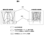
- a margin value map for adjusting the margin value is created using information etc. of the subject.
- a range setting pattern which is a range 505 obtained by combining the extraction region range created in steps S101 to S105 and the margin value to the scan range at the time of examination, it is difficult to follow individual differences among subjects In some cases. Therefore, the influence of the individual difference is eliminated by adjusting the margin value on the basis of the subject information which may be the individual difference of the subject.
- the individual difference of the subject is, for example, a physical difference.
- the size in the positioning image 601 is usually different between the standard figure-type subject shown on the left side of the figure and the petite-type subject shown on the right side. Therefore, if the same margin value 602 is applied to both, it may not be the scan range that is originally desired to be set. Therefore, as shown in FIG. 7, a map 701 of margin values corresponding to the physical constitution of the subject, such as height and weight, is prepared, and the physical size of the subject is examined using the map 701 at the time of examination. By referring to and applying the margin value corresponding to R, it is possible to set the range setting pattern as a scan range to be originally set. Further, a margin value assuming a standard figure type subject is designated in step S104, and a margin value map 701 in step S106 is created based on the margin value corresponding to the height and weight of the standard figure designated here. It is good.
- margin value map may be created using other subject information, and a plurality of margin value maps are created and referred to An average value may be applied.
- Step S107 Linking to Inspection Protocol
- the range setting pattern created in steps S101 to S105 is linked to the inspection protocol.
- the inspection protocol As a method of associating with the inspection protocol, for example, it may be set in units of inspection protocol or may be set in more detail in units of scan sequence or multirecon reconfiguration processing unit. Further, the setting may be made in units of examination site, and the automatic setting may be made available regardless of the use protocol at the time of examination.
- the information linked here is desirably stored in the storage device 123 or the like as in the inspection protocol. As described above, the pre-inspection part of the process flow for setting the scan range by creating the range setting pattern of FIG. 4 is completed, and thereafter, the processing at the time of inspection (S108 to S114) is started.
- Step S108 Acquisition of Subject Information
- subject information is acquired at the start of the examination.
- various information of the subject is input at the start of the examination, subject registration is performed, and stored in the storage device 123.
- the subject information acquired here is, for example, height or weight.
- Step S109 Positioning Image Photographing
- the operator sets an X-ray irradiation range including a region to be inspected, and photographs a positioning image.
- the positioning image is preferably photographed from at least one direction, for example, one of the position (0 °: PA direction) of the X-ray tube 101 in FIG. 1 and the position rotated by 90 ° (LAT direction).
- Step S110 Range setting pattern application
- the scanning range described above is performed according to the range setting pattern linked to the inspection protocol in step S107 without particularly performing an operation by the operator after positioning image photographing.
- the automatic setting unit applies the range setting pattern and automatically sets the scan range. Steps S111 to S114, which are steps of range setting pattern application, will be described in detail below.
- Step S111 Determination of Combination of Positioning Image and Inspection Object
- an extraction algorithm is applied to the positioning image captured in S109 to determine the number of times of extraction of the specified inspection object (hereinafter, extraction processing).
- the processing time of the extraction process is longer compared to the processing time of transmission and reception of examination information, and in particular, it is further increased when a plurality of range setting patterns are set in association with one examination protocol. Therefore, in order to minimize the processing time of the extraction process, the combination of the positioning image to be subjected to the extraction process and the inspection target is determined so as to minimize the number of times of processing.
- range setting pattern A test object: lung field, margin value: all 20
- range setting pattern B test object: lung field, margin value: all 30
- range setting pattern C test object: liver, margin A case where all the values 20
- the extracted regions shown in gray indicate the lung field and the liver to be examined, respectively. Since the range setting pattern A and the range setting pattern B have the same examination object in the lung field, the extraction region range 802 which is the extraction processing result for the same positioning image 801 is the same.
- the margin values 20 and 30 may be added to the extraction area range 802 to set as the scan range of the range setting pattern A and the range setting pattern B.
- a range setting pattern C in which the margin value 20 is added to the extraction area range 803 is set as a scan range. Therefore, the extraction process for the positioning image 801 in this case may be performed only twice.
- Step S112 Extraction of Inspection Target
- a specified inspection target is extracted from the positioning image 801.
- An arbitrary extraction algorithm is applied to the positioning image 801 to extract an object.
- the inspection object extraction method and extraction algorithm may be known methods, for example, may be a method as described in Patent Document 1.
- Step S113 Extraction Region Range Generation
- a rectangular extraction region range including the region extracted in S112 is generated.
- the smallest including each extracted area shown in gray Extraction area ranges 802 and 803 can be generated using a rectangular range.
- Step S114 Setting as a scan range
- the margin values 20, 20, and 30 specified in S104 are respectively added to the positions of the extraction area ranges 802 and 803 generated in S113 to calculate range parameters, and imaging conditions Set as the scan range of.
- the scan range automatic setting unit can reduce the time and labor of the operator and the inaccuracy of the scan range setting. It is possible to greatly improve.
- Second Embodiment A second embodiment will now be described with reference to FIGS.
- the second embodiment in addition to the content for automatically setting the scan range as in the first embodiment, an embodiment in which the influence of the height of the bed for setting the subject is considered will be described. That is, a map in which the relationship between the height of the bed on which the subject is placed and the image magnification of the positioning image are associated is stored in the storage unit, and the scan range automatic setting unit refers to the map and In this embodiment, the scan range is set by adjusting the margin value stored in the range setting pattern according to the bed height.
- the bed on which the subject is placed is mainly moved in the body axis direction and the body width direction to set the position where the subject to be photographed can be photographed, but the height of the bed may be adjusted.
- the maximum width of the X-ray irradiated to the subject 901 differs depending on the height of the bed 105, so the test in the positioning image 902
- the magnification of the person 901 (hereinafter, image magnification) is different.
- image magnification The magnification of the person 901
- the margin value may not be as intended by the operator. Therefore, it is necessary to adjust the margin value according to the height of the bed 105.
- the difference between the second embodiment and the first embodiment is that a map as shown in FIG. 10 in which the relationship between the height of the bed 105 and the image magnification is associated is created in advance, and the set margin value is inspected It is the point which adjusts according to the bed height at the time, and sets as a scan range.
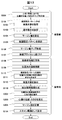
- FIG. 11 is a process flowchart for setting a scan range according to the second embodiment. Steps S101 to S114 in FIG. 11 are the same as in the first embodiment. Hereinafter, only portions different from the processing flow of the first embodiment will be described, and the description of the same portion will be omitted.
- Step S201 Creation of the bed height and the magnification map of the subject in the image
- a map in which the height of the bed is associated with the image magnification is created before the examination.
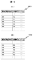
- the maximum X-ray width irradiated to the subject differs depending on the height of the bed, the lower the bed, the smaller the image magnification, and the larger the image magnification.
- FIG. 10 is an example of a map in which the height of the bed is associated with the image magnification when the magnification when the height of the bed is 200 mm is 1.0.
- the map 1001 of (a) of the figure corresponds to the case where the X-ray tube 101 is below the bed when the X-ray tube 101 is above the bed, and the map 1002 of FIG. There is.
- the image magnification is increased as the height of the bed is increased, and the image magnification is decreased if the X-ray tube 101 is on the lower side.
- Step S202 Selecting the Image Magnification Corresponding to the Bed Height from the Map
- the height of the bed 105 at the time of positioning image shooting is acquired in step S109, and the image magnification according to the acquired bed height Are selected from the map created in step S201.
- Step S203 Calculate Margin Value Using Image Magnification
- the margin value set in the range setting pattern is adjusted in accordance with the image magnification selected in step S202. For example, in the inspection protocol in which the range setting pattern A (margin value: all 20) is set, using the map 1001 of FIG. Adjust the margin value to 18. After that, the same process flow as in the first embodiment is executed.
- the scan range desired by the operator can be automatically set regardless of the height of the bed at the time of photographing, the inaccuracy of the scan range setting is further improved.
- a map for correlating the ECG waveform of the subject with the movement of the heart is stored in the storage unit, and the scan range automatic setting unit uses the heart radio waves of the subject acquired at the time of imaging the positioning image.
- This is an embodiment of a configuration in which the scan range is set by adjusting the margin value stored in the range setting pattern by referring to the map based on the shape.
- the parts of the body to be examined there are parts that are always moving and parts that are hardly moving or not moving at all.
- the examination target is an organ that is constantly moving
- the position and size of the organ may be different from those at the time of positioning image shooting, and when the examination target goes out during the main imaging from the set scan range, an image necessary for diagnosis Can not get. Therefore, it is necessary to set the scan range so that the examination target is included even when the position and size of the organ are different.
- the third embodiment when an organ having motion is to be inspected, displacement of the position and size of movement of the organ is estimated, and the margin value is calculated taking into consideration the influence of those.
- ECG gated imaging is generally used.
- a method hereinafter, retrospective scan
- the margin value is adjusted in accordance with the position and the size at the designated timing in order to designate the timing of imaging with respect to the electrocardiogram.
- the variable position / maximum size that can be taken during imaging is estimated, and the margin value is adjusted.
- the correspondence between the electrocardiogram waveform and the position / size of the heart is made in advance.
- the difference between the third embodiment and the previous embodiment is that a map for correlating the electrocardiogram waveform with the movement of the heart (fluctuating position, displacement of size) is prepared in advance, and the subject's The electrocardiographic waveform is acquired, the margin value is adjusted so as to be a scan range that includes the examination target with reference to the map, and the scan range is set.
- FIG. 13 is a process flowchart for setting a scan range according to the third embodiment.
- the examination object is the heart and the imaging method is the retrospective scan will be described.
- Steps S101 to S114 in FIG. 13 are the same as in the previous embodiment.
- only different parts from the previous embodiment will be described, and the description of the same parts will be omitted.
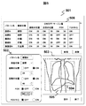
- Step S301 Map creation of the position and size of the heart in one cardiac cycle
- the position and size of the heart are associated with each heartbeat phase for one cardiac cycle based on a general electrocardiogram waveform.
- FIG. 12 shows an example in which the electrocardiogram 1202 is associated with the heart size 1201.
- the cardiac phase for one cardiac cycle is divided into times t1 to t7, and the heart size 1201 is minimum (here, t5).
- the map 1203 is an example of creating a map 1203 of the ratio to the size of.
- Step S109 Positioning Image Photographing
- electrocardiogram information such as heart rate phase is acquired.
- Step S302 Estimating the Heartbeat Phase at the Time of Positioning Image Shooting
- the heartbeat phase at the time of positioning image shooting (which position within one cardiac cycle) is estimated. .
- Step S303 Estimating the Position and Size of the Heart
- the fluctuation position and the maximum size of the heart which can be taken at the time of imaging are estimated.
- the size of the heart a map as shown in FIG. 12 is used, and based on the size of the cardiac phase at the time of positioning image photographing, the size at the cardiac phase of t3 which is the maximum size is determined. For example, if the cardiac phase at the time of imaging the positioning image is t4 in FIG. 12 and the size of the heart on the positioning image is 130 mm, the size of the heart that can be taken at the time of imaging is approximately 141.5 mm at maximum.
- Step S304 Calculate Margin Value
- the margin value set in the range setting pattern is used. Calculate the margin value to keep. That is, only the difference between the extraction region range for the positioning image and the range in the case of the heart fluctuation position / maximum size estimated in step S303 is added to the margin value set in the range setting pattern. For example, when the margin value of the range setting pattern is 20, the extraction area range for the positioning image is 130, and the maximum size is 140, the scan range is set to 160. That is, the margin value is adjusted to 30.
- the same method can be applied to other examination objects.
- the examination target is a lung field and diaphragm
- the position and size change at the timing of breathing.
- the positioning image photographing and the main photographing are performed in a breath-hold state, and the position and the size of the examination object coincide in both photographings.
- the position and the size of the examination object do not always coincide in both photographings. Therefore, a map is created by correlating the respiratory waveform etc. with the position and size of the lung field and diaphragm, and the possible position and size of the organ are estimated from the respiratory timing at the time of positioning image photography, and the margin value Adjust the
- the scan range automatic setting unit calculates the inclination ⁇ of the body axis of the subject with respect to the scan center line from the positioning image, and generates an image (hereinafter, ⁇ rotation image) obtained by rotating the positioning image by ⁇ . Then, an extraction area range is generated for the ⁇ rotation image, a scan range for the ⁇ rotation image (hereinafter, ⁇ rotation scan range) is calculated, and a value obtained by rotating the ⁇ rotation scan range by ⁇ is set as the scan range Of the configuration to be
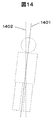
- the subject When the body axis 1401 of the subject is inclined with respect to the scan center line 1402, the subject is obliquely projected on the positioning image, and therefore, as shown in FIG.
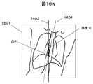
- the extraction area range and the range 1503 of the margin value do not become the scan range 1504 originally intended to be set, and there are portions where scanning is insufficient and portions where scanning is unnecessary. Therefore, it is necessary to set the extraction area range and the scan range in accordance with the degree of inclination of the subject. Therefore, the degree of inclination of the subject is determined from the positioning image, the extraction area range and the scan range when the subject is not inclined are determined, and the obtained scan range is inclined by the inclination of the subject Set
- the difference from the above-described embodiment is that, from the positioning image 1501, the angle ⁇ of inclination of the body axis 1401 of the subject with respect to the scan center line 1402 (counterclockwise) is positive.
- the calculated ⁇ rotation image 1601 is generated by rotating the positioning image 1501 by ⁇ , and an extraction area range is generated for the ⁇ rotation image 1601 as shown in FIG.
- the rotation scan range 1602 is calculated, and as shown in FIG. 16C, a value obtained by rotating the ⁇ rotation scan range 1602 by ⁇ is set as the scan range 1603.
- reference numeral 1604 denotes a center line of the scan range 1603.
- FIG. 17 is a process flowchart for setting a scan range according to the fourth embodiment. Steps S101 to S114 in FIG. 17 are the same as in the previous embodiment. Hereinafter, only different parts from the previous embodiment will be described, and the description of the same parts will be omitted.
- Step S401 Calculate the angle ⁇ and the point A
- the body axis 1401 of the subject is determined based on the positioning image 1501, and the scan center line 1402 and the body axis of the subject
- the angle ⁇ formed by 1401 and the intersection point A of the scan center line and the body axis of the subject are determined.
- the body axis 1401 of the subject may be determined, for example, by analyzing the CT value of the positioning image, or a sensor or a CCD camera may be mounted on the bed or the scan gantry unit to set the state of the subject separately. May be acquired and analyzed, or any other known method may be used.
- Step S402 Generation of ⁇ -Rotated Image
- a ⁇ -rotated image 1601 is generated by ⁇ -rotating the positioning image acquired in step S109 as shown in FIG. 16B.
- the ⁇ rotation image 1601 is an image corresponding to a positioning image captured when the scan center and the body axis of the subject are not inclined.
- a method of rotating for example, there is a method of using a rotation matrix expressed by the following equation.
- the following equation 1 calculates a point C (cx, cy) obtained by rotating the point B (bx, by) about the point A (ax, ay) by an angle ⁇ .
- the method to rotate may be a well-known method other than said number 1.
- Step S403 and S404 Calculating the ⁇ Rotational Range Parameter
- the ⁇ rotational range parameter is calculated from the ⁇ rotational image generated in step S402.
- Steps S112 and S113 are the same processes as in the above embodiment.
- step S404 the margin value set in the range setting pattern is added to the extraction region range for the ⁇ rotation image, the range parameter is calculated, and the ⁇ rotation range parameter is obtained.
- Step S405 Calculation of Range Parameter
- the ⁇ rotation range parameter calculated in step S404 is rotated by ⁇ to calculate the range parameter.
- the method of rotating may be the method described above or any other known method.
- Step S114 Setting as Scan Range
- the center line 1604 of the scan range 1603 calculated as in the above step is inclined with respect to the scan center line 1402 as shown in FIG. 16C.
- the collimator 103 is made a collimator that enables a fine radiation shape as proposed in JP-A-2015-59889.
- 16C may be scanned as in the scan range 1603 shown in FIG. 16C, and as long as it is an image creation range, it is not necessary to add a mechanical configuration in particular.
- the scan desired by the operator and the minimum exposure dose without excess or deficiency of data acquisition can be obtained. It becomes possible to set the scan range.
- the storage unit has an FOV (hereinafter referred to as extracted FOV) of the extraction region range for the positioning image, and an appropriate BH correction degree for reducing the influence of beam hardening (hereinafter referred to as BH) on the image.
- FOV hereinafter referred to as extracted FOV
- BH beam hardening
- a map that associates FOV at the time of shooting (hereinafter referred to as collection FOV) is stored, and the scan range automatic setting unit refers to the map and sets the collection FOV according to the extraction FOV as the scan range Of the configuration to be That is, in this embodiment, in addition to the contents of the above-described embodiment, an embodiment in which the acquisition FOV is set such that BH correction for reducing the influence of BH on an image in the X-ray CT apparatus is appropriate will be described. Do.
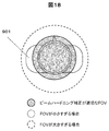
- the BH correction corrects the CT value on the assumption of the subject having the same size as the collected FOV, as shown in FIG. 18, the collected FOV set for the size of the subject 901 is appropriate as shown in FIG. If not, the BH correction is not appropriate, and CT value cupping and capping occur to adversely affect the image. Therefore, using the fact that the BH correction degree 1901 is determined for each collected FOV as shown in FIG. 19, the value of the collected FOV that results in an appropriate BH correction degree is set as the scan range according to the extracted FOV. .
- the difference from the previous embodiment is that a map in which the extracted FOV for the positioning image is associated with the acquired FOV that has an appropriate BH correction degree is created in advance, and the acquired FOV corresponding to the extracted FOV is This is a point set as a scan range.
- FIG. 20 is a process flowchart for setting a scan range according to the fifth embodiment. Steps S101 to S114 in FIG. 20 are the same as in the previous embodiment. Hereinafter, only different parts from the previous embodiment will be described, and the description of the same parts will be omitted.
- Step S501 Create a map of a collection FOV where the extraction FOV and the BH correction degree are optimal
- the BH correction degree 1901 is determined for each collection FOV as shown in FIG.
- a map is created in which the extracted FOV is associated with the value of the collected FOV that results in an appropriate BH correction degree.
- Step S502 Selecting a Collection FOV Corresponding to the Extracted FOV from the Map
- a collection FOV corresponding to the extraction FOV of the extraction area range generated in S113 is selected.
- the selected FOV of collection is set as a scan range. For example, either the value of FOV obtained in this embodiment or the value of FOV calculated by the method of the previous embodiment is set as a scan range. It is also possible to provide a means by which the user can select.
- the present embodiment it is possible to perform appropriate beam hardening correction while ensuring that the inspection object is in the scan range, so the inaccuracy of the scan range setting and the image quality are improved.
- the scan range automatic setting unit when the operator adjusts the scan range, the scan range automatic setting unit accumulates the scan range adjustment information, which is information obtained by adjusting the scan range, in the storage unit, and accumulates it at the next examination.
- the scan range adjustment information which is information obtained by adjusting the scan range, in the storage unit, and accumulates it at the next examination.
- Steps S101 to S114 in FIG. 21B are the same as in the previous embodiment.
- Steps S101 to S114 in FIG. 21B are the same as in the previous embodiment.
- steps S101 to S114 in FIG. 21B are the same as in the previous embodiment.
- Only different parts from the previous embodiment will be described, and the description of the same parts will be omitted.
- the flowchart of FIG. 21A will be described.
- Step S601 The scan range adjustment information is stored. After the scan range is set as in the previous embodiment, the operator manually adjusts the scan range, and after the actual shooting is performed, the scan range adjustment information is set. , Storage devices, etc.
- the scan range adjustment information includes, for example, the pattern of the positioning image, the height and weight of the subject, the region to be examined, the electrocardiogram information, the position of the extraction area range with respect to the positioning image, and the manually set scan range. Although the adjusted place and adjustment amount and various imaging conditions may be mentioned, information other than these may be stored together.
- Step S602 Margin Value Optimization
- the margin value of the range setting pattern is optimized based on the scan range adjustment information accumulated in step S601.
- a method using a machine learning program or other known methods may be used as an optimization method.
- Step S603 Use of Optimized Margin Value
- the margin value optimized in step S602 is applied.
- means may be provided to select which of the optimized margin value and the margin value calculated by the method of the embodiment is to be applied.
- the present invention is also applicable to other medical image diagnostic apparatuses or treatment apparatuses having a positioning image and acquiring a planning operation using the positioning image. .
- the present invention is not limited to the above-described embodiments, and includes various modifications.
- the embodiments described above have been described in detail for better understanding of the present invention, and are not necessarily limited to those having all the configurations of the description.
- part of the configuration of one embodiment can be replaced with the configuration of another embodiment, and the configuration of another embodiment can be added to the configuration of one embodiment.
Landscapes
- Health & Medical Sciences (AREA)
- Life Sciences & Earth Sciences (AREA)
- Engineering & Computer Science (AREA)
- Medical Informatics (AREA)
- Biomedical Technology (AREA)
- Surgery (AREA)
- High Energy & Nuclear Physics (AREA)
- Physics & Mathematics (AREA)
- Nuclear Medicine, Radiotherapy & Molecular Imaging (AREA)
- Optics & Photonics (AREA)
- Pathology (AREA)
- Radiology & Medical Imaging (AREA)
- Veterinary Medicine (AREA)
- Heart & Thoracic Surgery (AREA)
- Molecular Biology (AREA)
- Biophysics (AREA)
- Animal Behavior & Ethology (AREA)
- General Health & Medical Sciences (AREA)
- Public Health (AREA)
- Human Computer Interaction (AREA)
- Pulmonology (AREA)
- Theoretical Computer Science (AREA)
- Cardiology (AREA)
- Dentistry (AREA)
- Oral & Maxillofacial Surgery (AREA)
- Apparatus For Radiation Diagnosis (AREA)
Priority Applications (1)
| Application Number | Priority Date | Filing Date | Title |
|---|---|---|---|
| US16/630,611 US11096649B2 (en) | 2017-08-08 | 2018-04-05 | Medical image diagnostic device and image processing method |
Applications Claiming Priority (2)
| Application Number | Priority Date | Filing Date | Title |
|---|---|---|---|
| JP2017153011A JP6875954B2 (ja) | 2017-08-08 | 2017-08-08 | 医用画像診断装置、及び画像処理方法 |
| JP2017-153011 | 2017-08-08 |
Publications (1)
| Publication Number | Publication Date |
|---|---|
| WO2019030975A1 true WO2019030975A1 (ja) | 2019-02-14 |
Family
ID=65271248
Family Applications (1)
| Application Number | Title | Priority Date | Filing Date |
|---|---|---|---|
| PCT/JP2018/014588 Ceased WO2019030975A1 (ja) | 2017-08-08 | 2018-04-05 | 医用画像診断装置、及び画像処理方法 |
Country Status (3)
| Country | Link |
|---|---|
| US (1) | US11096649B2 (https=) |
| JP (1) | JP6875954B2 (https=) |
| WO (1) | WO2019030975A1 (https=) |
Cited By (2)
| Publication number | Priority date | Publication date | Assignee | Title |
|---|---|---|---|---|
| JP2022023836A (ja) * | 2020-07-27 | 2022-02-08 | キヤノンメディカルシステムズ株式会社 | 評価装置、評価プログラム及び評価システム |
| CN116958128A (zh) * | 2023-09-18 | 2023-10-27 | 中南大学 | 基于深度学习的医学图像自动定位方法 |
Families Citing this family (5)
| Publication number | Priority date | Publication date | Assignee | Title |
|---|---|---|---|---|
| JP6875596B2 (ja) | 2018-03-01 | 2021-05-26 | 富士フイルム株式会社 | 音響波診断装置および音響波診断装置の制御方法 |
| CN110755075B (zh) * | 2019-10-30 | 2023-07-25 | 上海联影医疗科技股份有限公司 | 磁共振成像方法、装置、设备和存储介质 |
| JP2023098344A (ja) * | 2021-12-28 | 2023-07-10 | キヤノンメディカルシステムズ株式会社 | 医用画像診断装置、医用画像診断システム及びスキャン範囲の設定方法 |
| CN116712095A (zh) * | 2023-06-30 | 2023-09-08 | 苏州晟诺医疗科技有限公司 | 待扫描对象摆位偏移的补偿的方法、装置、介质和电子设备 |
| JP2025128733A (ja) * | 2024-02-22 | 2025-09-03 | 富士フイルム株式会社 | 情報処理装置、医療画像撮影装置、情報処理方法、及び情報処理プログラム |
Citations (4)
| Publication number | Priority date | Publication date | Assignee | Title |
|---|---|---|---|---|
| JP2012000448A (ja) * | 2010-05-17 | 2012-01-05 | Toshiba Corp | 画像処理装置及びx線ct装置 |
| US20120213326A1 (en) * | 2009-10-22 | 2012-08-23 | Koninklijke Philips Electronics N.V. | Scan parameter policy |
| JP2015213748A (ja) * | 2014-04-21 | 2015-12-03 | 株式会社東芝 | X線コンピュータ断層撮影装置及びスキャン計画設定支援装置 |
| JP2015213749A (ja) * | 2014-04-21 | 2015-12-03 | 株式会社東芝 | X線コンピュータ断層撮影装置及び撮影条件設定支援装置 |
Family Cites Families (3)
| Publication number | Priority date | Publication date | Assignee | Title |
|---|---|---|---|---|
| JP6258938B2 (ja) * | 2012-08-27 | 2018-01-10 | コーニンクレッカ フィリップス エヌ ヴェKoninklijke Philips N.V. | 光学3dシーン検出及び解釈に基づく患者個別型及び自動x線システム調節 |
| CN103892862B (zh) | 2012-12-28 | 2018-12-25 | Ge医疗系统环球技术有限公司 | 用于侦查图像的自动扫描定位装置 |
| TWI606752B (zh) * | 2016-10-28 | 2017-11-21 | Iner Aec | 用於數位x光機的自動曝露控制系統與其方法 |
-
2017
- 2017-08-08 JP JP2017153011A patent/JP6875954B2/ja active Active
-
2018
- 2018-04-05 US US16/630,611 patent/US11096649B2/en active Active
- 2018-04-05 WO PCT/JP2018/014588 patent/WO2019030975A1/ja not_active Ceased
Patent Citations (4)
| Publication number | Priority date | Publication date | Assignee | Title |
|---|---|---|---|---|
| US20120213326A1 (en) * | 2009-10-22 | 2012-08-23 | Koninklijke Philips Electronics N.V. | Scan parameter policy |
| JP2012000448A (ja) * | 2010-05-17 | 2012-01-05 | Toshiba Corp | 画像処理装置及びx線ct装置 |
| JP2015213748A (ja) * | 2014-04-21 | 2015-12-03 | 株式会社東芝 | X線コンピュータ断層撮影装置及びスキャン計画設定支援装置 |
| JP2015213749A (ja) * | 2014-04-21 | 2015-12-03 | 株式会社東芝 | X線コンピュータ断層撮影装置及び撮影条件設定支援装置 |
Cited By (4)
| Publication number | Priority date | Publication date | Assignee | Title |
|---|---|---|---|---|
| JP2022023836A (ja) * | 2020-07-27 | 2022-02-08 | キヤノンメディカルシステムズ株式会社 | 評価装置、評価プログラム及び評価システム |
| JP7648465B2 (ja) | 2020-07-27 | 2025-03-18 | キヤノンメディカルシステムズ株式会社 | 評価装置、評価プログラム及び評価システム |
| CN116958128A (zh) * | 2023-09-18 | 2023-10-27 | 中南大学 | 基于深度学习的医学图像自动定位方法 |
| CN116958128B (zh) * | 2023-09-18 | 2023-12-26 | 中南大学 | 基于深度学习的医学图像自动定位方法 |
Also Published As
| Publication number | Publication date |
|---|---|
| US20210077054A1 (en) | 2021-03-18 |
| US11096649B2 (en) | 2021-08-24 |
| JP2019030478A (ja) | 2019-02-28 |
| JP6875954B2 (ja) | 2021-05-26 |
Similar Documents
| Publication | Publication Date | Title |
|---|---|---|
| JP6875954B2 (ja) | 医用画像診断装置、及び画像処理方法 | |
| CN110139607B (zh) | 用于患者扫描设置的方法和系统 | |
| CN104997528B (zh) | X 射线计算机断层拍摄装置以及拍摄条件设定辅助装置 | |
| CN104586417B (zh) | 增大锥束计算机层析成像获取中的视场的方法和成像设备 | |
| US11497459B2 (en) | Methods and system for optimizing an imaging scan based on a prior scan | |
| RU2550542C2 (ru) | Способ и устройство для формирования компьютерных томографических изображений с использованием геометрий со смещенным детектором | |
| JP4532005B2 (ja) | X線ct装置及びその画像表示方法 | |
| CN104955396B (zh) | X射线ct装置以及图像重构方法 | |
| JP6929689B2 (ja) | 医用画像処理装置及び医用画像診断装置 | |
| JP6906905B2 (ja) | X線診断装置 | |
| CN109419526A (zh) | 用于数字乳房断层合成中的运动评估和校正的方法和系统 | |
| JP5588697B2 (ja) | X線ct装置 | |
| JP4429694B2 (ja) | X線ct装置 | |
| JP5179788B2 (ja) | 医用画像診断装置、その制御方法及びプログラム | |
| JP2003299643A (ja) | 断層撮影装置 | |
| JP5027909B2 (ja) | X線ct装置 | |
| CN107106112B (zh) | X射线ct装置、图像处理装置及图像重构方法 | |
| WO2006090321A1 (en) | Determination of the coverage of a ct scan | |
| WO2006085253A2 (en) | Computer tomography apparatus, method of examining an object of interest with a computer tomography apparatus, computer-readable medium and program element | |
| JP2017113081A (ja) | X線ct装置及び撮影方法 | |
| JP4644292B2 (ja) | X線ct装置とその画像表示方法 | |
| JP6877881B2 (ja) | 医用画像処理装置、x線ct装置及び画像処理方法 | |
| JP5384293B2 (ja) | X線ct装置 | |
| JP2006288739A (ja) | X線ct装置 | |
| CN120514406A (zh) | 信息处理装置、医疗图像摄影装置、信息处理方法及计算机程序产品 |
Legal Events
| Date | Code | Title | Description |
|---|---|---|---|
| 121 | Ep: the epo has been informed by wipo that ep was designated in this application |
Ref document number: 18844413 Country of ref document: EP Kind code of ref document: A1 |
|
| NENP | Non-entry into the national phase |
Ref country code: DE |
|
| 122 | Ep: pct application non-entry in european phase |
Ref document number: 18844413 Country of ref document: EP Kind code of ref document: A1 |