WO2019030975A1 - 医用画像診断装置、及び画像処理方法 - Google Patents
医用画像診断装置、及び画像処理方法 Download PDFInfo
- Publication number
- WO2019030975A1 WO2019030975A1 PCT/JP2018/014588 JP2018014588W WO2019030975A1 WO 2019030975 A1 WO2019030975 A1 WO 2019030975A1 JP 2018014588 W JP2018014588 W JP 2018014588W WO 2019030975 A1 WO2019030975 A1 WO 2019030975A1
- Authority
- WO
- WIPO (PCT)
- Prior art keywords
- range
- scan range
- medical image
- scan
- subject
- Prior art date
Links
- 238000003672 processing method Methods 0.000 title claims description 7
- 238000007689 inspection Methods 0.000 claims abstract description 68
- 238000000605 extraction Methods 0.000 claims abstract description 60
- 238000003384 imaging method Methods 0.000 claims abstract description 44
- 238000012937 correction Methods 0.000 claims description 14
- 230000033001 locomotion Effects 0.000 claims description 6
- 230000001678 irradiating effect Effects 0.000 claims description 5
- 238000002059 diagnostic imaging Methods 0.000 claims 1
- 239000000284 extract Substances 0.000 abstract 1
- 238000000034 method Methods 0.000 description 44
- 238000012545 processing Methods 0.000 description 23
- 238000002591 computed tomography Methods 0.000 description 22
- 230000008569 process Effects 0.000 description 15
- 238000010586 diagram Methods 0.000 description 14
- 210000004072 lung Anatomy 0.000 description 11
- 230000000747 cardiac effect Effects 0.000 description 8
- 210000000056 organ Anatomy 0.000 description 8
- 238000004364 calculation method Methods 0.000 description 7
- 238000003745 diagnosis Methods 0.000 description 4
- 210000004185 liver Anatomy 0.000 description 4
- 238000012360 testing method Methods 0.000 description 4
- 230000005855 radiation Effects 0.000 description 3
- 230000015572 biosynthetic process Effects 0.000 description 2
- 230000008859 change Effects 0.000 description 2
- 210000003109 clavicle Anatomy 0.000 description 2
- 238000006073 displacement reaction Methods 0.000 description 2
- 230000006870 function Effects 0.000 description 2
- 238000002595 magnetic resonance imaging Methods 0.000 description 2
- 238000005259 measurement Methods 0.000 description 2
- 238000005457 optimization Methods 0.000 description 2
- 230000000241 respiratory effect Effects 0.000 description 2
- 206010006322 Breath holding Diseases 0.000 description 1
- 230000002411 adverse Effects 0.000 description 1
- 210000003484 anatomy Anatomy 0.000 description 1
- 230000005540 biological transmission Effects 0.000 description 1
- 238000013480 data collection Methods 0.000 description 1
- 230000003247 decreasing effect Effects 0.000 description 1
- 230000007812 deficiency Effects 0.000 description 1
- 238000001514 detection method Methods 0.000 description 1
- 230000006866 deterioration Effects 0.000 description 1
- 230000000694 effects Effects 0.000 description 1
- 238000005516 engineering process Methods 0.000 description 1
- 239000004973 liquid crystal related substance Substances 0.000 description 1
- 239000011159 matrix material Substances 0.000 description 1
- 230000007246 mechanism Effects 0.000 description 1
- 238000012986 modification Methods 0.000 description 1
- 230000004048 modification Effects 0.000 description 1
- 238000007781 pre-processing Methods 0.000 description 1
- 230000029058 respiratory gaseous exchange Effects 0.000 description 1
- 230000001360 synchronised effect Effects 0.000 description 1
Images


Classifications
-
- A—HUMAN NECESSITIES
- A61—MEDICAL OR VETERINARY SCIENCE; HYGIENE
- A61B—DIAGNOSIS; SURGERY; IDENTIFICATION
- A61B6/00—Apparatus or devices for radiation diagnosis; Apparatus or devices for radiation diagnosis combined with radiation therapy equipment
- A61B6/02—Arrangements for diagnosis sequentially in different planes; Stereoscopic radiation diagnosis
- A61B6/03—Computed tomography [CT]
- A61B6/032—Transmission computed tomography [CT]
-
- A—HUMAN NECESSITIES
- A61—MEDICAL OR VETERINARY SCIENCE; HYGIENE
- A61B—DIAGNOSIS; SURGERY; IDENTIFICATION
- A61B6/00—Apparatus or devices for radiation diagnosis; Apparatus or devices for radiation diagnosis combined with radiation therapy equipment
- A61B6/40—Arrangements for generating radiation specially adapted for radiation diagnosis
-
- A—HUMAN NECESSITIES
- A61—MEDICAL OR VETERINARY SCIENCE; HYGIENE
- A61B—DIAGNOSIS; SURGERY; IDENTIFICATION
- A61B6/00—Apparatus or devices for radiation diagnosis; Apparatus or devices for radiation diagnosis combined with radiation therapy equipment
- A61B6/42—Arrangements for detecting radiation specially adapted for radiation diagnosis
-
- A—HUMAN NECESSITIES
- A61—MEDICAL OR VETERINARY SCIENCE; HYGIENE
- A61B—DIAGNOSIS; SURGERY; IDENTIFICATION
- A61B6/00—Apparatus or devices for radiation diagnosis; Apparatus or devices for radiation diagnosis combined with radiation therapy equipment
- A61B6/46—Arrangements for interfacing with the operator or the patient
- A61B6/461—Displaying means of special interest
- A61B6/465—Displaying means of special interest adapted to display user selection data, e.g. graphical user interface, icons or menus
-
- A—HUMAN NECESSITIES
- A61—MEDICAL OR VETERINARY SCIENCE; HYGIENE
- A61B—DIAGNOSIS; SURGERY; IDENTIFICATION
- A61B6/00—Apparatus or devices for radiation diagnosis; Apparatus or devices for radiation diagnosis combined with radiation therapy equipment
- A61B6/46—Arrangements for interfacing with the operator or the patient
- A61B6/467—Arrangements for interfacing with the operator or the patient characterised by special input means
-
- A—HUMAN NECESSITIES
- A61—MEDICAL OR VETERINARY SCIENCE; HYGIENE
- A61B—DIAGNOSIS; SURGERY; IDENTIFICATION
- A61B6/00—Apparatus or devices for radiation diagnosis; Apparatus or devices for radiation diagnosis combined with radiation therapy equipment
- A61B6/50—Apparatus or devices for radiation diagnosis; Apparatus or devices for radiation diagnosis combined with radiation therapy equipment specially adapted for specific body parts; specially adapted for specific clinical applications
- A61B6/503—Apparatus or devices for radiation diagnosis; Apparatus or devices for radiation diagnosis combined with radiation therapy equipment specially adapted for specific body parts; specially adapted for specific clinical applications for diagnosis of the heart
-
- A—HUMAN NECESSITIES
- A61—MEDICAL OR VETERINARY SCIENCE; HYGIENE
- A61B—DIAGNOSIS; SURGERY; IDENTIFICATION
- A61B6/00—Apparatus or devices for radiation diagnosis; Apparatus or devices for radiation diagnosis combined with radiation therapy equipment
- A61B6/54—Control of apparatus or devices for radiation diagnosis
- A61B6/545—Control of apparatus or devices for radiation diagnosis involving automatic set-up of acquisition parameters
-
- A—HUMAN NECESSITIES
- A61—MEDICAL OR VETERINARY SCIENCE; HYGIENE
- A61B—DIAGNOSIS; SURGERY; IDENTIFICATION
- A61B6/00—Apparatus or devices for radiation diagnosis; Apparatus or devices for radiation diagnosis combined with radiation therapy equipment
- A61B6/04—Positioning of patients; Tiltable beds or the like
- A61B6/0407—Supports, e.g. tables or beds, for the body or parts of the body
-
- A—HUMAN NECESSITIES
- A61—MEDICAL OR VETERINARY SCIENCE; HYGIENE
- A61B—DIAGNOSIS; SURGERY; IDENTIFICATION
- A61B6/00—Apparatus or devices for radiation diagnosis; Apparatus or devices for radiation diagnosis combined with radiation therapy equipment
- A61B6/44—Constructional features of apparatus for radiation diagnosis
- A61B6/4429—Constructional features of apparatus for radiation diagnosis related to the mounting of source units and detector units
- A61B6/4435—Constructional features of apparatus for radiation diagnosis related to the mounting of source units and detector units the source unit and the detector unit being coupled by a rigid structure
-
- A—HUMAN NECESSITIES
- A61—MEDICAL OR VETERINARY SCIENCE; HYGIENE
- A61B—DIAGNOSIS; SURGERY; IDENTIFICATION
- A61B6/00—Apparatus or devices for radiation diagnosis; Apparatus or devices for radiation diagnosis combined with radiation therapy equipment
- A61B6/46—Arrangements for interfacing with the operator or the patient
- A61B6/467—Arrangements for interfacing with the operator or the patient characterised by special input means
- A61B6/469—Arrangements for interfacing with the operator or the patient characterised by special input means for selecting a region of interest [ROI]
-
- A—HUMAN NECESSITIES
- A61—MEDICAL OR VETERINARY SCIENCE; HYGIENE
- A61B—DIAGNOSIS; SURGERY; IDENTIFICATION
- A61B6/00—Apparatus or devices for radiation diagnosis; Apparatus or devices for radiation diagnosis combined with radiation therapy equipment
- A61B6/54—Control of apparatus or devices for radiation diagnosis
- A61B6/541—Control of apparatus or devices for radiation diagnosis involving acquisition triggered by a physiological signal
-
- A—HUMAN NECESSITIES
- A61—MEDICAL OR VETERINARY SCIENCE; HYGIENE
- A61B—DIAGNOSIS; SURGERY; IDENTIFICATION
- A61B6/00—Apparatus or devices for radiation diagnosis; Apparatus or devices for radiation diagnosis combined with radiation therapy equipment
- A61B6/54—Control of apparatus or devices for radiation diagnosis
- A61B6/542—Control of apparatus or devices for radiation diagnosis involving control of exposure
- A61B6/544—Control of apparatus or devices for radiation diagnosis involving control of exposure dependent on patient size
Definitions
- the present invention relates to a medical image diagnostic apparatus, and more particularly to a technique for setting an X-ray irradiation range and an image creation range in main imaging using a positioning image acquired before main imaging.
- Medical image diagnostic apparatuses are indispensable in current medical care, and one of them is an X-ray CT (Computed Tomography) apparatus.
- An X-ray CT apparatus rotates an X-ray source for irradiating an X-ray to a subject and an X-ray detector for detecting an X-ray dose transmitted through the subject as projection data around the subject.
- the tomographic image of the subject is reconstructed using projection data from a plurality of angles obtained by the above-mentioned method, and the reconstructed tomographic image is displayed.
- the image displayed by the X-ray CT apparatus describes the shape of an organ in a subject and is used for medical image diagnosis.
- Other medical image diagnostic apparatuses include an MRI (Magnetic Resonance Imaging) apparatus and the like. In the present specification, an X-ray CT apparatus will be described as an example.
- the X-ray CT apparatus In the X-ray CT apparatus, generally, before performing the main imaging, imaging of a positioning image for the main imaging plan to the subject is performed. The operator sets an X-ray irradiation range and an image formation range in main imaging by operating a line or the like on the positioning image, and sets various imaging parameters. In the present specification, two of the X-ray irradiation range and the image formation range are collectively referred to as a scan range.
- the medical image diagnostic apparatus of each manufacturer is equipped with a mechanism capable of setting beforehand the imaging conditions recommended by the guidelines or the like as a protocol before the examination, and most of the imaging conditions do not have to be changed at the time of the examination.
- Patent Document 1 the X-ray irradiation range set at the time of the main imaging planning is automatically set in order to improve the time-consuming and inaccuracies of the scan range setting manually performed by the operator. That is being tried.
- the feature amount is extracted from the positioning image and the range extracted using the feature amount is set as the scan range, but the criteria for setting the scan range for each hospital or operator are slightly different . Therefore, in the method of setting the scan range on the basis of uniform criteria, the operator is not set to the scan range that the operator originally wants to set, and eventually the operator has to manually manipulate the scan range, which is the initial purpose of the inspection The operator's scan range setting is less effective in improving the effort and inaccuracies.
- An object of the present invention is to provide a medical image diagnostic apparatus and an image processing method which can cope with setting criteria of a scan range different for each hospital and operator and can improve the time and inaccuracy of the operator at the time of scan range setting. It is to do.
- the present invention is a medical image diagnostic apparatus, and a storage unit that stores a range setting pattern in which an inspection object is associated with a margin value, and an inspection protocol, and a subject And a scan range automatic setting unit configured to automatically set a scan range at the time of examination in accordance with the range setting pattern associated with the examination protocol after taking a positioning image obtained by photographing the subject. .
- the present invention is an image processing method of a medical image diagnostic apparatus having a storage unit and a control unit, and a range setting pattern in which an inspection object and a margin value are associated with each other in the storage unit.
- the examination protocol are linked and stored, and the control unit takes a positioning image obtained by photographing the subject and then scans the scan range at the time of examination according to the range setting pattern associated with the examination protocol.
- the present invention provides an image processing method configured to automatically set
- the present invention it is possible to cope with the setting reference of the scan range which is different for each hospital and operator, and to improve the time and inaccuracy of the operator when setting the scan range.
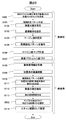
- FIG. 6 is a diagram showing a process flow for setting a scan range according to the first embodiment.
- FIG. 7 is a diagram showing an example of a range setting pattern creation screen in which an inspection target and a margin value are associated with each other according to the first embodiment. It is a figure for demonstrating the influence by the individual difference of a subject based on Example 1.
- FIG. FIG. 7 is a diagram showing an example of a margin value map according to the first embodiment.
- FIG. 6 is a diagram for explaining generation of an extraction region range according to the first embodiment. It is a figure for demonstrating the difference of the irradiation X-ray maximum width by the height of a bed based on Example 2.
- FIG. It is a figure which shows the example of the map which matched the height of the bed, and the magnification of the to-be-examined person in an image based on Example 2.
- FIG. FIG. 8 is a diagram showing a process flow for setting a scan range according to a second embodiment.
- FIG. 16 is a diagram showing an example in which an electrocardiogram waveform and a heart size are associated according to a third embodiment.
- FIG. 18 is a diagram illustrating a processing flow for setting a scan range according to a third embodiment.
- FIG. 21 is a diagram for explaining a scan range calculation method in the case where a body axis of a subject is inclined according to a fourth embodiment. It is a following figure for demonstrating the scan range calculation method when the body axis
- FIG. FIG. 21 is a diagram for explaining a scan range calculation method in the case where a body axis of a subject is inclined according to a fourth embodiment. It is a following figure for demonstrating the scan range calculation method when the body axis
- FIG. 18 is a diagram illustrating a process flow for setting a scan range according to a fourth embodiment.
- FIG. 18 is a diagram for explaining the size of the collected FOV and the subject according to the fifth embodiment.
- FIG. 18 is a diagram for explaining the relationship between the acquisition FOV and the beam hardening correction according to the fifth embodiment.
- FIG. 18 is a diagram illustrating a process flow for setting a scan range according to a fifth embodiment.
- FIG. 18 is a diagram illustrating a pre-processing flow for scan range setting according to a sixth embodiment.
- FIG. 18 is a diagram illustrating a process flow for setting a scan range according to a sixth embodiment.
- the scan range 202 which is automatically set may not coincide with the scan range 203 which the operator originally wants to set.
- feature amounts are extracted from the positioning image 201, and a range based on the extracted feature amounts is set as a scan range 202.
- the criteria for setting the scan range for each hospital or operator are slightly different.
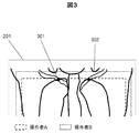
- FIG. 3 shows the difference in the reference for setting the position on the head side of the scan range when the lung field is imaged for the same examination purpose.
- the operator A uses "the intersection 301 between the clavicle and the ribs" as a guide
- the operator B uses "a shoulder recess 302 formed between the raised arm and the head” as a guide.
- the operator does not set the scan range that the operator originally wants to set, and eventually the operator needs to manually adjust the scan range. It is less effective in improving the time and inaccuracies in setting the scan range of the operator, which is the original purpose.
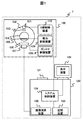
- the X-ray CT apparatus 1 comprises a scan gantry unit 100 and a console 120.
- the scan gantry unit 100 includes an X-ray tube 101, a rotating disk 102, a collimator 103, an X-ray detector 106, a data acquisition device 107, a bed 105, a gantry control device 108, and a bed control device 109. And an X-ray controller 110.
- the X-ray tube 101 is an apparatus for irradiating a subject placed on the bed 105 with X-rays.
- the collimator 103 is a device that limits the radiation range of X-rays emitted from the X-ray tube 101.
- the rotary disk 102 is provided with an opening 104 for receiving the subject placed on the bed 105, and is mounted with the X-ray tube 101 and the X-ray detector 106, and rotates around the subject. .
- the X-ray detector 106 is a device arranged to face the X-ray tube 101 and measure the spatial distribution of the transmitted X-rays by detecting the X-rays transmitted through the subject.
- the data acquisition device 107 is a device that acquires the X-ray dose detected by the X-ray detector 106 as digital data.
- the gantry control device 108 is a device that controls the rotation of the rotating disk 102.
- the bed control device 109 is a device that controls the up and down movement of the bed 105.
- the X-ray controller 110 is a device that controls the power input to the X-ray tube 101.
- the console 120 includes an input device 121, an image calculation device 122, a display device 125, a storage device 123, and a system control device 124.
- a console 120 can be realized by a personal computer (PC), a server or the like provided with a normal computer configuration.
- the input device 121 is a device for inputting an examinee's name, examination date and time, imaging conditions and the like, and more specifically, is a keyboard or a pointing device.
- the image calculation unit 122 is a unit that calculates and processes measurement data sent from the data acquisition unit 107 to reconstruct a CT image.
- the display device 125 is a device that displays the CT image created by the image processing device 122, and specifically, is a CRT (Cathode-Ray Tube), a liquid crystal display, or the like.
- the storage device 123 is a device that stores data collected by the data collection device 107 and image data of a CT image created by the image calculation device 122, and is specifically an HDD (Hard Disk Drive) or the like.
- the system control device 124 is a control unit of the entire device that controls these devices and the gantry control device 108, the bed control device 109, and the X-ray control device 110.
- the X-ray control device 110 controls the power input to the X-ray tube 101 based on imaging conditions such as a scan range input from the input device 121, in particular, X-ray tube voltage, X-ray tube current, etc.
- the tube 101 irradiates the subject with X-rays according to the imaging conditions.
- the X-ray detector 106 detects X-rays emitted from the X-ray tube 101 and transmitted through the subject with a number of X-ray detection elements, and measures the distribution of the transmitted X-rays.
- the rotating disk 102 is controlled by the gantry controller 108, and rotates based on the imaging conditions, particularly the rotational speed, input from the input device 121.
- the bed 105 is controlled by the bed control device 109, and operates based on the imaging conditions input from the input device 121, in particular, the helical pitch and the like.
- the X-ray irradiation from the X-ray tube 101 and the measurement of the transmitted X-ray distribution by the X-ray detector 106 are repeated along with the rotation of the rotating disk 102 to acquire projection data from various angles.
- the acquired projection data from various angles is transmitted to the image processing unit 122.
- the image processing unit 122 reconstructs a CT image by back-projecting the projection data transmitted from various angles.
- the CT image obtained by the reconstruction is displayed on the display device 125.
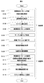
- the X-ray CT apparatus that executes this flowchart associates a range setting pattern in which the inspection target is associated with the margin value with the inspection protocol, stores the storage unit, and acquires a positioning image obtained by imaging the subject. After imaging, a scan range automatic setting unit that automatically sets a scan range at the time of inspection according to the range setting pattern linked to the inspection protocol is provided.
- the scan range setting flow is divided into before inspection (S101 to S107) and at inspection (S108 to S114).
- the main processing of this flowchart is the operator, the image processing unit 122, the system control unit 124, etc., and the processing is executed by the program execution of the central processing unit (CPU) of the PC constituting the image processing unit 122 or the system control unit 124. Is done.
- the inspection target specified by the operator is extracted from the positioning image, an extraction area range including the inspection target is generated, and the operator uses the GUI to obtain an arbitrary width for this extraction area range.
- a range setting pattern in which the determined margin values are associated is generated, and an automatic setting process of a scan range at the time of inspection by the scan range automatic setting unit that links the generated range setting pattern to the inspection protocol is realized. That is, the scan range automatic setting unit controls the display device 125 as the display unit to display the positioning image and the range setting pattern based on the margin value input from the input unit. Furthermore, as will be described later, the scan range automatic setting unit controls the display unit to display a list of range setting patterns stored in the storage unit.
- Step S101 Range Setting Pattern Creation
- the operator creates a range setting pattern in the pre-inspection flow.
- the range setting pattern indicates a range set as a scan range at the time of inspection as will be described later.
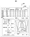
- the range setting pattern is preferably set by the operator on the GUI. For example, it is created on the range setting pattern creation screen 501 of FIG. 5 which is an example of the GUI.
- a positioning image 503 on the creation screen As shown on the lower right side of FIG. 5, a positioning image 503 on the creation screen, a line indicating the position of the extraction area range 504 on the positioning image 503, a range 505 obtained by combining the extraction area range and the margin value serving as a range setting pattern. Display a line indicating the position of.
- the positioning image 503 displayed on the screen may be, for example, an image of a human phantom that imitates the anatomical structure of a human body, or may be a positioning image of a subject acquired when the examination was performed in the past.
- a line indicating the position of the extraction area range 504 is extracted by applying an arbitrary extraction algorithm to the positioning image 503.
- the method of extraction may be a known method.
- the operator designates the pattern name of the range setting pattern, the inspection target, the application location, the margin value and the like by the range setting pattern detail setting unit 502.
- the main steps S102 to S105 involved in the creation of the range setting pattern will be described in detail below.
- Step S102 Designation of Examination Target
- the operator designates a pattern name such as “lung field A” set arbitrarily, and designates the examination target of the range setting pattern by an arbitrary method.
- a method may be used in which a part name and the position of the body are associated in advance and designated as "lung field” or the like, or a method of designating an arbitrary part on a human body imitation drawing.
- the positioning image of the whole body may always be displayed.
- a plurality of inspection targets may be specified for one range setting pattern.
- Step S103 Setting an Application Part
- the operator sets whether or not to apply automatic setting for each item for determining a scan range (hereinafter, range parameter).
- the range parameter is, for example, the position on the head side, the position on the foot side, the FOV (Field of View), the FOV center, etc. shown on the lower left side of FIG.
- the range setting pattern detail setting unit 502 is used to set application / non-application (ON / OFF) of automatic setting.
- medical image diagnosis there is a case where the deterioration of the image reading efficiency is prevented by fixing only the FOV to a designated value when comparing the image with the past photographed image.
- the configuration of this embodiment can cope with such a case, and the versatility is enhanced.
- the range parameter set to “Apply (represented as ON in FIG. 5)” for the value applied at the time of inspection the combined value of the extraction area range and the margin value is applied as the imaging condition and reflected in the range setting pattern Ru.
- the range parameter set to "not applied (represented as OFF in FIG. 5)" for example, a form for setting a default value is prepared on the range setting pattern creation screen of FIG. 5 and a value input there is used Alternatively, the inspection protocol may be registered in advance, and the set value may be used.
- Step S104 Designate Margin Value
- the operator designates a margin value for each range parameter with respect to the position of the extraction area range.
- This margin value is the value of the margin in the range 505 set as the scan range at the time of inspection.
- the margin value may be designated by numerical input using the range setting pattern detail setting unit 502 as shown in FIG. 5, for example, or designated by operating the line indicating the range 505 displayed on the positioning image with the mouse You may.
- the unit of the margin value may be a unit of the shooting position (such as millimeter), or may be the number of pixels on the image.
- Step S105 Save Range Setting Pattern
- the range setting pattern in which the extraction area range created with the content specified by the operator is associated with the margin value is saved in the storage unit such as the storage device 123.
- a plurality of range setting patterns stored and accumulated in the storage unit may be displayed as the list 506.
- the list 506 displays each pattern name and ON / OFF / margin values according to the inspection target. The operator can use the buttons on the GUI screen as appropriate to save, create new, delete, and end creation of the range setting pattern.
- Step S106 Margin Value Map Creation
- a margin value map for adjusting the margin value is created using information etc. of the subject.
- a range setting pattern which is a range 505 obtained by combining the extraction region range created in steps S101 to S105 and the margin value to the scan range at the time of examination, it is difficult to follow individual differences among subjects In some cases. Therefore, the influence of the individual difference is eliminated by adjusting the margin value on the basis of the subject information which may be the individual difference of the subject.
- the individual difference of the subject is, for example, a physical difference.
- the size in the positioning image 601 is usually different between the standard figure-type subject shown on the left side of the figure and the petite-type subject shown on the right side. Therefore, if the same margin value 602 is applied to both, it may not be the scan range that is originally desired to be set. Therefore, as shown in FIG. 7, a map 701 of margin values corresponding to the physical constitution of the subject, such as height and weight, is prepared, and the physical size of the subject is examined using the map 701 at the time of examination. By referring to and applying the margin value corresponding to R, it is possible to set the range setting pattern as a scan range to be originally set. Further, a margin value assuming a standard figure type subject is designated in step S104, and a margin value map 701 in step S106 is created based on the margin value corresponding to the height and weight of the standard figure designated here. It is good.
- margin value map may be created using other subject information, and a plurality of margin value maps are created and referred to An average value may be applied.
- Step S107 Linking to Inspection Protocol
- the range setting pattern created in steps S101 to S105 is linked to the inspection protocol.
- the inspection protocol As a method of associating with the inspection protocol, for example, it may be set in units of inspection protocol or may be set in more detail in units of scan sequence or multirecon reconfiguration processing unit. Further, the setting may be made in units of examination site, and the automatic setting may be made available regardless of the use protocol at the time of examination.
- the information linked here is desirably stored in the storage device 123 or the like as in the inspection protocol. As described above, the pre-inspection part of the process flow for setting the scan range by creating the range setting pattern of FIG. 4 is completed, and thereafter, the processing at the time of inspection (S108 to S114) is started.
- Step S108 Acquisition of Subject Information
- subject information is acquired at the start of the examination.
- various information of the subject is input at the start of the examination, subject registration is performed, and stored in the storage device 123.
- the subject information acquired here is, for example, height or weight.
- Step S109 Positioning Image Photographing
- the operator sets an X-ray irradiation range including a region to be inspected, and photographs a positioning image.
- the positioning image is preferably photographed from at least one direction, for example, one of the position (0 °: PA direction) of the X-ray tube 101 in FIG. 1 and the position rotated by 90 ° (LAT direction).
- Step S110 Range setting pattern application
- the scanning range described above is performed according to the range setting pattern linked to the inspection protocol in step S107 without particularly performing an operation by the operator after positioning image photographing.
- the automatic setting unit applies the range setting pattern and automatically sets the scan range. Steps S111 to S114, which are steps of range setting pattern application, will be described in detail below.
- Step S111 Determination of Combination of Positioning Image and Inspection Object
- an extraction algorithm is applied to the positioning image captured in S109 to determine the number of times of extraction of the specified inspection object (hereinafter, extraction processing).
- the processing time of the extraction process is longer compared to the processing time of transmission and reception of examination information, and in particular, it is further increased when a plurality of range setting patterns are set in association with one examination protocol. Therefore, in order to minimize the processing time of the extraction process, the combination of the positioning image to be subjected to the extraction process and the inspection target is determined so as to minimize the number of times of processing.
- range setting pattern A test object: lung field, margin value: all 20
- range setting pattern B test object: lung field, margin value: all 30
- range setting pattern C test object: liver, margin A case where all the values 20
- the extracted regions shown in gray indicate the lung field and the liver to be examined, respectively. Since the range setting pattern A and the range setting pattern B have the same examination object in the lung field, the extraction region range 802 which is the extraction processing result for the same positioning image 801 is the same.
- the margin values 20 and 30 may be added to the extraction area range 802 to set as the scan range of the range setting pattern A and the range setting pattern B.
- a range setting pattern C in which the margin value 20 is added to the extraction area range 803 is set as a scan range. Therefore, the extraction process for the positioning image 801 in this case may be performed only twice.
- Step S112 Extraction of Inspection Target
- a specified inspection target is extracted from the positioning image 801.
- An arbitrary extraction algorithm is applied to the positioning image 801 to extract an object.
- the inspection object extraction method and extraction algorithm may be known methods, for example, may be a method as described in Patent Document 1.
- Step S113 Extraction Region Range Generation
- a rectangular extraction region range including the region extracted in S112 is generated.
- the smallest including each extracted area shown in gray Extraction area ranges 802 and 803 can be generated using a rectangular range.
- Step S114 Setting as a scan range
- the margin values 20, 20, and 30 specified in S104 are respectively added to the positions of the extraction area ranges 802 and 803 generated in S113 to calculate range parameters, and imaging conditions Set as the scan range of.
- the scan range automatic setting unit can reduce the time and labor of the operator and the inaccuracy of the scan range setting. It is possible to greatly improve.
- Second Embodiment A second embodiment will now be described with reference to FIGS.
- the second embodiment in addition to the content for automatically setting the scan range as in the first embodiment, an embodiment in which the influence of the height of the bed for setting the subject is considered will be described. That is, a map in which the relationship between the height of the bed on which the subject is placed and the image magnification of the positioning image are associated is stored in the storage unit, and the scan range automatic setting unit refers to the map and In this embodiment, the scan range is set by adjusting the margin value stored in the range setting pattern according to the bed height.
- the bed on which the subject is placed is mainly moved in the body axis direction and the body width direction to set the position where the subject to be photographed can be photographed, but the height of the bed may be adjusted.
- the maximum width of the X-ray irradiated to the subject 901 differs depending on the height of the bed 105, so the test in the positioning image 902
- the magnification of the person 901 (hereinafter, image magnification) is different.
- image magnification The magnification of the person 901
- the margin value may not be as intended by the operator. Therefore, it is necessary to adjust the margin value according to the height of the bed 105.
- the difference between the second embodiment and the first embodiment is that a map as shown in FIG. 10 in which the relationship between the height of the bed 105 and the image magnification is associated is created in advance, and the set margin value is inspected It is the point which adjusts according to the bed height at the time, and sets as a scan range.
- FIG. 11 is a process flowchart for setting a scan range according to the second embodiment. Steps S101 to S114 in FIG. 11 are the same as in the first embodiment. Hereinafter, only portions different from the processing flow of the first embodiment will be described, and the description of the same portion will be omitted.
- Step S201 Creation of the bed height and the magnification map of the subject in the image
- a map in which the height of the bed is associated with the image magnification is created before the examination.
- the maximum X-ray width irradiated to the subject differs depending on the height of the bed, the lower the bed, the smaller the image magnification, and the larger the image magnification.
- FIG. 10 is an example of a map in which the height of the bed is associated with the image magnification when the magnification when the height of the bed is 200 mm is 1.0.
- the map 1001 of (a) of the figure corresponds to the case where the X-ray tube 101 is below the bed when the X-ray tube 101 is above the bed, and the map 1002 of FIG. There is.
- the image magnification is increased as the height of the bed is increased, and the image magnification is decreased if the X-ray tube 101 is on the lower side.
- Step S202 Selecting the Image Magnification Corresponding to the Bed Height from the Map
- the height of the bed 105 at the time of positioning image shooting is acquired in step S109, and the image magnification according to the acquired bed height Are selected from the map created in step S201.
- Step S203 Calculate Margin Value Using Image Magnification
- the margin value set in the range setting pattern is adjusted in accordance with the image magnification selected in step S202. For example, in the inspection protocol in which the range setting pattern A (margin value: all 20) is set, using the map 1001 of FIG. Adjust the margin value to 18. After that, the same process flow as in the first embodiment is executed.
- the scan range desired by the operator can be automatically set regardless of the height of the bed at the time of photographing, the inaccuracy of the scan range setting is further improved.
- a map for correlating the ECG waveform of the subject with the movement of the heart is stored in the storage unit, and the scan range automatic setting unit uses the heart radio waves of the subject acquired at the time of imaging the positioning image.
- This is an embodiment of a configuration in which the scan range is set by adjusting the margin value stored in the range setting pattern by referring to the map based on the shape.
- the parts of the body to be examined there are parts that are always moving and parts that are hardly moving or not moving at all.
- the examination target is an organ that is constantly moving
- the position and size of the organ may be different from those at the time of positioning image shooting, and when the examination target goes out during the main imaging from the set scan range, an image necessary for diagnosis Can not get. Therefore, it is necessary to set the scan range so that the examination target is included even when the position and size of the organ are different.
- the third embodiment when an organ having motion is to be inspected, displacement of the position and size of movement of the organ is estimated, and the margin value is calculated taking into consideration the influence of those.
- ECG gated imaging is generally used.
- a method hereinafter, retrospective scan
- the margin value is adjusted in accordance with the position and the size at the designated timing in order to designate the timing of imaging with respect to the electrocardiogram.
- the variable position / maximum size that can be taken during imaging is estimated, and the margin value is adjusted.
- the correspondence between the electrocardiogram waveform and the position / size of the heart is made in advance.
- the difference between the third embodiment and the previous embodiment is that a map for correlating the electrocardiogram waveform with the movement of the heart (fluctuating position, displacement of size) is prepared in advance, and the subject's The electrocardiographic waveform is acquired, the margin value is adjusted so as to be a scan range that includes the examination target with reference to the map, and the scan range is set.
- FIG. 13 is a process flowchart for setting a scan range according to the third embodiment.
- the examination object is the heart and the imaging method is the retrospective scan will be described.
- Steps S101 to S114 in FIG. 13 are the same as in the previous embodiment.
- only different parts from the previous embodiment will be described, and the description of the same parts will be omitted.
- Step S301 Map creation of the position and size of the heart in one cardiac cycle
- the position and size of the heart are associated with each heartbeat phase for one cardiac cycle based on a general electrocardiogram waveform.
- FIG. 12 shows an example in which the electrocardiogram 1202 is associated with the heart size 1201.
- the cardiac phase for one cardiac cycle is divided into times t1 to t7, and the heart size 1201 is minimum (here, t5).
- the map 1203 is an example of creating a map 1203 of the ratio to the size of.
- Step S109 Positioning Image Photographing
- electrocardiogram information such as heart rate phase is acquired.
- Step S302 Estimating the Heartbeat Phase at the Time of Positioning Image Shooting
- the heartbeat phase at the time of positioning image shooting (which position within one cardiac cycle) is estimated. .
- Step S303 Estimating the Position and Size of the Heart
- the fluctuation position and the maximum size of the heart which can be taken at the time of imaging are estimated.
- the size of the heart a map as shown in FIG. 12 is used, and based on the size of the cardiac phase at the time of positioning image photographing, the size at the cardiac phase of t3 which is the maximum size is determined. For example, if the cardiac phase at the time of imaging the positioning image is t4 in FIG. 12 and the size of the heart on the positioning image is 130 mm, the size of the heart that can be taken at the time of imaging is approximately 141.5 mm at maximum.
- Step S304 Calculate Margin Value
- the margin value set in the range setting pattern is used. Calculate the margin value to keep. That is, only the difference between the extraction region range for the positioning image and the range in the case of the heart fluctuation position / maximum size estimated in step S303 is added to the margin value set in the range setting pattern. For example, when the margin value of the range setting pattern is 20, the extraction area range for the positioning image is 130, and the maximum size is 140, the scan range is set to 160. That is, the margin value is adjusted to 30.
- the same method can be applied to other examination objects.
- the examination target is a lung field and diaphragm
- the position and size change at the timing of breathing.
- the positioning image photographing and the main photographing are performed in a breath-hold state, and the position and the size of the examination object coincide in both photographings.
- the position and the size of the examination object do not always coincide in both photographings. Therefore, a map is created by correlating the respiratory waveform etc. with the position and size of the lung field and diaphragm, and the possible position and size of the organ are estimated from the respiratory timing at the time of positioning image photography, and the margin value Adjust the
- the scan range automatic setting unit calculates the inclination ⁇ of the body axis of the subject with respect to the scan center line from the positioning image, and generates an image (hereinafter, ⁇ rotation image) obtained by rotating the positioning image by ⁇ . Then, an extraction area range is generated for the ⁇ rotation image, a scan range for the ⁇ rotation image (hereinafter, ⁇ rotation scan range) is calculated, and a value obtained by rotating the ⁇ rotation scan range by ⁇ is set as the scan range Of the configuration to be
- the subject When the body axis 1401 of the subject is inclined with respect to the scan center line 1402, the subject is obliquely projected on the positioning image, and therefore, as shown in FIG.
- the extraction area range and the range 1503 of the margin value do not become the scan range 1504 originally intended to be set, and there are portions where scanning is insufficient and portions where scanning is unnecessary. Therefore, it is necessary to set the extraction area range and the scan range in accordance with the degree of inclination of the subject. Therefore, the degree of inclination of the subject is determined from the positioning image, the extraction area range and the scan range when the subject is not inclined are determined, and the obtained scan range is inclined by the inclination of the subject Set
- the difference from the above-described embodiment is that, from the positioning image 1501, the angle ⁇ of inclination of the body axis 1401 of the subject with respect to the scan center line 1402 (counterclockwise) is positive.
- the calculated ⁇ rotation image 1601 is generated by rotating the positioning image 1501 by ⁇ , and an extraction area range is generated for the ⁇ rotation image 1601 as shown in FIG.
- the rotation scan range 1602 is calculated, and as shown in FIG. 16C, a value obtained by rotating the ⁇ rotation scan range 1602 by ⁇ is set as the scan range 1603.
- reference numeral 1604 denotes a center line of the scan range 1603.
- FIG. 17 is a process flowchart for setting a scan range according to the fourth embodiment. Steps S101 to S114 in FIG. 17 are the same as in the previous embodiment. Hereinafter, only different parts from the previous embodiment will be described, and the description of the same parts will be omitted.
- Step S401 Calculate the angle ⁇ and the point A
- the body axis 1401 of the subject is determined based on the positioning image 1501, and the scan center line 1402 and the body axis of the subject
- the angle ⁇ formed by 1401 and the intersection point A of the scan center line and the body axis of the subject are determined.
- the body axis 1401 of the subject may be determined, for example, by analyzing the CT value of the positioning image, or a sensor or a CCD camera may be mounted on the bed or the scan gantry unit to set the state of the subject separately. May be acquired and analyzed, or any other known method may be used.
- Step S402 Generation of ⁇ -Rotated Image
- a ⁇ -rotated image 1601 is generated by ⁇ -rotating the positioning image acquired in step S109 as shown in FIG. 16B.
- the ⁇ rotation image 1601 is an image corresponding to a positioning image captured when the scan center and the body axis of the subject are not inclined.
- a method of rotating for example, there is a method of using a rotation matrix expressed by the following equation.
- the following equation 1 calculates a point C (cx, cy) obtained by rotating the point B (bx, by) about the point A (ax, ay) by an angle ⁇ .
- the method to rotate may be a well-known method other than said number 1.
- Step S403 and S404 Calculating the ⁇ Rotational Range Parameter
- the ⁇ rotational range parameter is calculated from the ⁇ rotational image generated in step S402.
- Steps S112 and S113 are the same processes as in the above embodiment.
- step S404 the margin value set in the range setting pattern is added to the extraction region range for the ⁇ rotation image, the range parameter is calculated, and the ⁇ rotation range parameter is obtained.
- Step S405 Calculation of Range Parameter
- the ⁇ rotation range parameter calculated in step S404 is rotated by ⁇ to calculate the range parameter.
- the method of rotating may be the method described above or any other known method.
- Step S114 Setting as Scan Range
- the center line 1604 of the scan range 1603 calculated as in the above step is inclined with respect to the scan center line 1402 as shown in FIG. 16C.
- the collimator 103 is made a collimator that enables a fine radiation shape as proposed in JP-A-2015-59889.
- 16C may be scanned as in the scan range 1603 shown in FIG. 16C, and as long as it is an image creation range, it is not necessary to add a mechanical configuration in particular.
- the scan desired by the operator and the minimum exposure dose without excess or deficiency of data acquisition can be obtained. It becomes possible to set the scan range.
- the storage unit has an FOV (hereinafter referred to as extracted FOV) of the extraction region range for the positioning image, and an appropriate BH correction degree for reducing the influence of beam hardening (hereinafter referred to as BH) on the image.
- FOV hereinafter referred to as extracted FOV
- BH beam hardening
- a map that associates FOV at the time of shooting (hereinafter referred to as collection FOV) is stored, and the scan range automatic setting unit refers to the map and sets the collection FOV according to the extraction FOV as the scan range Of the configuration to be That is, in this embodiment, in addition to the contents of the above-described embodiment, an embodiment in which the acquisition FOV is set such that BH correction for reducing the influence of BH on an image in the X-ray CT apparatus is appropriate will be described. Do.
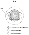
- the BH correction corrects the CT value on the assumption of the subject having the same size as the collected FOV, as shown in FIG. 18, the collected FOV set for the size of the subject 901 is appropriate as shown in FIG. If not, the BH correction is not appropriate, and CT value cupping and capping occur to adversely affect the image. Therefore, using the fact that the BH correction degree 1901 is determined for each collected FOV as shown in FIG. 19, the value of the collected FOV that results in an appropriate BH correction degree is set as the scan range according to the extracted FOV. .
- the difference from the previous embodiment is that a map in which the extracted FOV for the positioning image is associated with the acquired FOV that has an appropriate BH correction degree is created in advance, and the acquired FOV corresponding to the extracted FOV is This is a point set as a scan range.
- FIG. 20 is a process flowchart for setting a scan range according to the fifth embodiment. Steps S101 to S114 in FIG. 20 are the same as in the previous embodiment. Hereinafter, only different parts from the previous embodiment will be described, and the description of the same parts will be omitted.
- Step S501 Create a map of a collection FOV where the extraction FOV and the BH correction degree are optimal
- the BH correction degree 1901 is determined for each collection FOV as shown in FIG.
- a map is created in which the extracted FOV is associated with the value of the collected FOV that results in an appropriate BH correction degree.
- Step S502 Selecting a Collection FOV Corresponding to the Extracted FOV from the Map
- a collection FOV corresponding to the extraction FOV of the extraction area range generated in S113 is selected.
- the selected FOV of collection is set as a scan range. For example, either the value of FOV obtained in this embodiment or the value of FOV calculated by the method of the previous embodiment is set as a scan range. It is also possible to provide a means by which the user can select.
- the present embodiment it is possible to perform appropriate beam hardening correction while ensuring that the inspection object is in the scan range, so the inaccuracy of the scan range setting and the image quality are improved.
- the scan range automatic setting unit when the operator adjusts the scan range, the scan range automatic setting unit accumulates the scan range adjustment information, which is information obtained by adjusting the scan range, in the storage unit, and accumulates it at the next examination.
- the scan range adjustment information which is information obtained by adjusting the scan range, in the storage unit, and accumulates it at the next examination.
- Steps S101 to S114 in FIG. 21B are the same as in the previous embodiment.
- Steps S101 to S114 in FIG. 21B are the same as in the previous embodiment.
- steps S101 to S114 in FIG. 21B are the same as in the previous embodiment.
- Only different parts from the previous embodiment will be described, and the description of the same parts will be omitted.
- the flowchart of FIG. 21A will be described.
- Step S601 The scan range adjustment information is stored. After the scan range is set as in the previous embodiment, the operator manually adjusts the scan range, and after the actual shooting is performed, the scan range adjustment information is set. , Storage devices, etc.
- the scan range adjustment information includes, for example, the pattern of the positioning image, the height and weight of the subject, the region to be examined, the electrocardiogram information, the position of the extraction area range with respect to the positioning image, and the manually set scan range. Although the adjusted place and adjustment amount and various imaging conditions may be mentioned, information other than these may be stored together.
- Step S602 Margin Value Optimization
- the margin value of the range setting pattern is optimized based on the scan range adjustment information accumulated in step S601.
- a method using a machine learning program or other known methods may be used as an optimization method.
- Step S603 Use of Optimized Margin Value
- the margin value optimized in step S602 is applied.
- means may be provided to select which of the optimized margin value and the margin value calculated by the method of the embodiment is to be applied.
- the present invention is also applicable to other medical image diagnostic apparatuses or treatment apparatuses having a positioning image and acquiring a planning operation using the positioning image. .
- the present invention is not limited to the above-described embodiments, and includes various modifications.
- the embodiments described above have been described in detail for better understanding of the present invention, and are not necessarily limited to those having all the configurations of the description.
- part of the configuration of one embodiment can be replaced with the configuration of another embodiment, and the configuration of another embodiment can be added to the configuration of one embodiment.
Landscapes
- Health & Medical Sciences (AREA)
- Life Sciences & Earth Sciences (AREA)
- Engineering & Computer Science (AREA)
- Medical Informatics (AREA)
- Heart & Thoracic Surgery (AREA)
- Animal Behavior & Ethology (AREA)
- Biophysics (AREA)
- Nuclear Medicine, Radiotherapy & Molecular Imaging (AREA)
- Optics & Photonics (AREA)
- Pathology (AREA)
- Radiology & Medical Imaging (AREA)
- Biomedical Technology (AREA)
- Physics & Mathematics (AREA)
- Molecular Biology (AREA)
- Surgery (AREA)
- High Energy & Nuclear Physics (AREA)
- General Health & Medical Sciences (AREA)
- Public Health (AREA)
- Veterinary Medicine (AREA)
- Human Computer Interaction (AREA)
- Cardiology (AREA)
- Dentistry (AREA)
- Oral & Maxillofacial Surgery (AREA)
- Pulmonology (AREA)
- Theoretical Computer Science (AREA)
- Apparatus For Radiation Diagnosis (AREA)
Abstract
病院や技師ごとに異なるX線照射範囲及び画像作成範囲の設定基準に対し、漏れなく所望するX線照射範囲及び画像作成範囲を自動で設定できる仕組みを提供する。X線CT装置において、スキャン範囲自動設定部は、検査前に操作者が指定した任意の体の部位である検査対象を位置決め画像から抽出し、それを含む抽出領域範囲を生成し、抽出領域範囲に対して操作者がGUIを使用して任意のマージン値をライン操作または数値入力で設定し(S104)、検査対象とマージン値とを対応付けた範囲設定パターンを生成保存し(S105)。さらにこの範囲設定パターンを検査プロトコルに紐づけする(S106)。そして、位置決め画像撮影(S109)直後に、位置決め画像から検査対象を抽出し(S112)、検査対象に対応付けられ、検査プロトコルに紐づけられた範囲設定パターンに従いスキャン範囲を自動で設定する(S114)。
Description
本発明は、医用画像診断装置に係り、特に本撮影前に取得した位置決め画像を使用して本撮影におけるX線照射範囲および画像作成範囲を設定する技術に関する。
医用画像診断装置は、現在の医療において必要不可欠なものであり、その1つとしてX線CT(Computed Tomography)装置がある。X線CT装置とは、被検者にX線を照射するX線源と、被検者を透過したX線量を投影データとして検出するX線検出器とを被検者の周囲で回転させることにより得られる複数角度からの投影データを用いて被検者の断層画像を再構成し、再構成された断層画像を表示するものである。X線CT装置で表示される画像は、被検者の中の臓器の形状を描写するものであり、医用画像診断に使用される。医用画像診断装置としては、その他MRI(Magnetic Resonance Imaging)装置などがあるが、以下本明細書においては一例としてX線CT装置の場合について記載する。
X線CT装置においては、一般的に本撮影を行う前に、被検者に対する本撮影計画用の位置決め画像の撮影が行われる。操作者は位置決め画像上でライン等を操作することにより本撮影におけるX線照射範囲及び画像作成範囲を設定するとともに、様々な撮影パラメータを設定する。なお、本明細書ではX線照射範囲と画像作成範囲の2つをまとめてスキャン範囲と呼ぶ。
本撮影計画には、撮影部位や検査目的ごとに分けて記載されたガイドラインが存在し、ガイドラインを参考にして本撮影計画を行えばある程度統一された撮影条件で本撮影を行うことが可能である。また、各メーカーの医用画像診断装置には、ガイドライン等で推奨された撮影条件をプロトコルとして検査前に予め設定できる仕組みが搭載されており、ほとんどの撮影条件は検査時に変更しなくても良い。
しかしながら、ガイドラインやプロトコルを利用した本撮影計画には限界がある。特に上述のスキャン範囲の設定は、被検者ごとに位置決め画像が異なるため、プロトコルで設定しておいたスキャン範囲のままでは不適切な場合が多く、適切な範囲を設定するためには操作者の経験が必要である。そのため、ほとんどの場合が検査時に操作者による手作業でのスキャン範囲設定が必要となり、スキャン範囲設定には不正確性が生じる。
特許文献1に示すような従来技術では、操作者が手作業で行っていたスキャン範囲設定の手間や不正確性を改善するため、本撮影計画時に設定するX線照射範囲を自動的に設定することが試みられている。
上述した従来技術においては、位置決め画像より特徴量を抽出し、特徴量を使って抽出した範囲をスキャン範囲として設定しているが、病院や操作者ごとにスキャン範囲を設定する基準はわずかに異なる。そのため、一律の基準でスキャン範囲を設定する方法では、操作者が本来設定したいスキャン範囲に設定されず、結局操作者がスキャン範囲を手作業で操作する必要が生じ、当初の目的である検査時の操作者のスキャン範囲設定の手間や不正確性を改善する効果が少なくなっている。
本発明の目的は、病院や操作者ごとに異なるスキャン範囲の設定基準に対応し、スキャン範囲設定の際の操作者の手間や不正確性を改善できる医用画像診断装置、及び画像処理方法を提供することにある。
上記目的を達成するために、本発明は、医用画像診断装置であって、検査対象とマージン値を対応付けた範囲設定パターンと、検査プロトコルとを紐付けて記憶する記憶部と、被検者を撮影して得られる位置決め画像を撮影後、検査プロトコルに紐付けされた範囲設定パターンに従い、検査時のスキャン範囲を自動設定するスキャン範囲自動設定部とを備える構成の医用画像診断装置を提供する。
また、上記目的を達成するため、本発明は、記憶部と制御部とを有する医用画像診断装置の画像処理方法であって、記憶部に、検査対象とマージン値とを対応付けた範囲設定パターンと、検査プロトコルとを紐付けて記憶しておき、制御部は、被検者を撮影して得られる位置決め画像を撮影後、検査プロトコルに紐付けされた範囲設定パターンに従い、検査時のスキャン範囲を自動設定する構成の画像処理方法を提供する。
本発明によれば、病院や操作者ごとに異なるスキャン範囲の設定基準に対応し、スキャン範囲設定の際の操作者の手間や不正確性を改善できる。
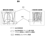
上述した課題を解決可能な本発明の種々の実施例を順次説明する。まず本発明の理解を容易にするため、本発明が解決する課題を図面により説明する。図2に示すように、従来の自動設定方法においては、自動で設定されるスキャン範囲202と操作者が本来設定したいスキャン範囲203が一致しない場合がある。この方法では、位置決め画像201より特徴量を抽出し、抽出した特徴量に基づく範囲をスキャン範囲202として設定している。しかしながら、上述したように病院や操作者ごとにスキャン範囲を設定する基準はわずかに異なる。
例えば、図3は同じ検査目的で肺野を撮影する場合における、スキャン範囲の頭側の位置を設定する基準の違いを示している。操作者Aは「鎖骨と肋骨の交点301」を目安にしており、操作者Bは「上げた腕と頭の間にできる肩の窪み302」を目安にしている。このような場合、特許文献1のように一律の基準でスキャン範囲を設定する方法では、操作者が本来設定したいスキャン範囲に設定されず、結局操作者がスキャン範囲を手作業で調整する必要が生じ、当初の目的である操作者のスキャン範囲設定の手間や不正確性を改善する効果が少ない。
最初に図1を使って各実施例が適用されるX線CT装置の全体構成の一例を説明する。
X線CT装置1はスキャンガントリ部100と操作卓120とを備える。スキャンガントリ部100は、X線管101と、回転円盤102と、コリメータ103と、X線検出器106と、データ収集装置107と、寝台105と、ガントリ制御装置108と、寝台制御装置109と、X線制御装置110と、を備えている。
X線CT装置1はスキャンガントリ部100と操作卓120とを備える。スキャンガントリ部100は、X線管101と、回転円盤102と、コリメータ103と、X線検出器106と、データ収集装置107と、寝台105と、ガントリ制御装置108と、寝台制御装置109と、X線制御装置110と、を備えている。
X線管101は寝台105上に載置された被検者にX線を照射する装置である。コリメータ103はX線管101から照射されるX線の放射範囲を制限する装置である。回転円盤102は、寝台105上に載置された被検者が入る開口部104を備えるとともに、X線管101とX線検出器106を搭載し、被検者の周囲を回転するものである。X線検出器106は、X線管101と対向配置され被検者を透過したX線を検出することにより透過X線の空間的な分布を計測する装置であり、多数のX線検出素子を回転円盤102の回転方向に配列したもの、若しくは回転円盤102の回転方向と回転軸方向との2次元に配列したものである。データ収集装置107は、X線検出器106で検出されたX線量をデジタルデータとして収集する装置である。ガントリ制御装置108は回転円盤102の回転を制御する装置である。寝台制御装置109は、寝台105の上下前後動を制御する装置である。X線制御装置110はX線管101に入力される電力を制御する装置である。
操作卓120は、入力装置121と、画像演算装置122と、表示装置125と、記憶装置123と、システム制御装置124とを備えている。このような操作卓120は通常のコンピュータ構成を備えたパーソナルコンピュータ(PC)やサーバ等で実現できる。入力装置121は、被検者氏名、検査日時、撮影条件などを入力するための装置であり、具体的にはキーボードやポインティングデバイスである。画像演算装置122は、データ収集装置107から送出される計測データを演算処理してCT画像再構成を行う装置である。表示装置125は、画像演算装置122で作成されたCT画像を表示する装置であり、具体的にはCRT(Cathode-Ray Tube)や液晶ディスプレイ等である。記憶装置123は、データ収集装置107で収集したデータ及び画像演算装置122で作成されたCT画像の画像データを記憶する装置であり、具体的にはHDD(Hard Disk Drive)等である。システム制御装置124は、これらの装置及びガントリ制御装置108と寝台制御装置109とX線制御装置110を制御する装置全体の制御部である。
入力装置121から入力されたスキャン範囲などの撮影条件、特にX線管電圧やX線管電流などに基づきX線制御装置110がX線管101に入力される電力を制御することにより、X線管101は撮影条件に応じたX線を被検者に照射する。X線検出器106は、X線管101から照射され被検者を透過したX線を多数のX線検出素子で検出し、透過X線の分布を計測する。回転円盤102はガントリ制御装置108により制御され、入力装置121から入力された撮影条件、特に回転速度などに基づいて回転する。寝台105は寝台制御装置109によって制御され、入力装置121から入力された撮影条件、特にらせんピッチなどに基づいて動作する。
X線管101からのX線照射とX線検出器106による透過X線分布の計測が回転円盤102の回転とともに繰り返されることにより、様々な角度からの投影データが取得される。取得された様々な角度からの投影データは画像演算装置122に送信される。画像演算装置122は送信された様々な角度からの投影データを逆投影処理することによりCT画像を再構成する。
再構成して得られたCT画像は表示装置125に表示される。
再構成して得られたCT画像は表示装置125に表示される。
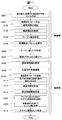
次に、実施例1のX線CT装置におけるスキャン範囲設定のための処理について、図4のフローチャートに沿って説明する。このフローチャートを実行するX線CT装置は、検査対象とマージン値を対応付けた範囲設定パターンと、検査プロトコルとを紐付けて記憶する記憶部と、被検者を撮影して得られる位置決め画像を撮影後、検査プロトコルに紐付けされた範囲設定パターンに従い、検査時のスキャン範囲を自動設定するスキャン範囲自動設定部とを備えている。
同図に示すようにスキャン範囲設定フローは、検査前(S101~S107)と検査時(S108~S114)に分かれる。なお、このフローチャートの処理主体は、操作者および画像演算装置122とシステム制御装置124などであり、画像演算装置122やシステム制御装置124を構成するPCの中央処理部(CPU)のプログラム実行により処理が行われる。この処理により、例えば、操作者が指定した検査対象を位置決め画像から抽出し、この検査対象を含む抽出領域範囲を生成し、この抽出領域範囲に対して操作者がGUIを使用して任意の幅に決定したマージン値を対応付けた範囲設定パターンを生成し、生成した範囲設定パターンを検査プロトコルに紐づけするスキャン範囲自動設定部による検査時のスキャン範囲の自動設定処理が実現される。すなわち、スキャン範囲自動設定部は、表示部である表示装置125に位置決め画像と、入力部から入力されるマージン値に基づく範囲設定パターンを表示するよう制御する。更に、後で説明するように、スキャン範囲自動設定部は、表示部に、記憶部に記憶した範囲設定パターンのリストを表示するよう制御する。
(ステップS101)範囲設定パターン作成
操作者は、検査前フローにおいて範囲設定パターンの作成を行う。この範囲設定パターンは、後で説明するように検査時にスキャン範囲として設定される範囲を示している。範囲設定パターンは、操作者がGUI上で設定することが望ましい。例えば、GUIの一例である図5の範囲設定パターン作成画面501上で作成する。図5の下段右側に示すように、作成画面上に位置決め画像503、位置決め画像503上に抽出領域範囲504の位置を示すライン、範囲設定パターンとなる、抽出領域範囲とマージン値を合わせた範囲505の位置を示すラインを表示する。すなわち検査時にスキャン範囲として設定される範囲設定パターンの範囲505の位置を示すラインをGUI上に表示することによって、操作者は検査時のスキャン範囲を想像しやすくなる。本実施例の構成により、検査時に抽出される範囲の目安が検査前にGUI画面上で視覚的に把握できるため、検査時において操作者が設定したいスキャン範囲と一致させる精度を高くできる。
操作者は、検査前フローにおいて範囲設定パターンの作成を行う。この範囲設定パターンは、後で説明するように検査時にスキャン範囲として設定される範囲を示している。範囲設定パターンは、操作者がGUI上で設定することが望ましい。例えば、GUIの一例である図5の範囲設定パターン作成画面501上で作成する。図5の下段右側に示すように、作成画面上に位置決め画像503、位置決め画像503上に抽出領域範囲504の位置を示すライン、範囲設定パターンとなる、抽出領域範囲とマージン値を合わせた範囲505の位置を示すラインを表示する。すなわち検査時にスキャン範囲として設定される範囲設定パターンの範囲505の位置を示すラインをGUI上に表示することによって、操作者は検査時のスキャン範囲を想像しやすくなる。本実施例の構成により、検査時に抽出される範囲の目安が検査前にGUI画面上で視覚的に把握できるため、検査時において操作者が設定したいスキャン範囲と一致させる精度を高くできる。
なお、この画面上に表示する位置決め画像503は、例えば、人体の解剖的構造を模した人体ファントムの画像でも良いし、過去に検査した際に取得した被検者の位置決め画像でも良い。抽出領域範囲504の位置を示すラインは、位置決め画像503に対して任意の抽出アルゴリズムを適用して抽出される。抽出する方法は公知の方法でも良い。この検査対象とマージン値を対応付けた範囲設定パターンの作成のため、操作者は範囲設定パターンのパターン名、検査対象、適用箇所、マージン値などを範囲設定パターン詳細設定部502で指定する。範囲設定パターンの作成にかかわる主なステップであるS102~S105について以下に詳述する。
(ステップS102)検査対象を指定
まず操作者は、任意に設定した「肺野A」などのパターン名を指定し、範囲設定パターンの検査対象を任意の方法により指定する。例えば、部位名と体の位置を予め関連付けて置き、「肺野」などと指定する方法でも良いし、人体模造図に対して任意の部分を指定するような方法でも良い。
まず操作者は、任意に設定した「肺野A」などのパターン名を指定し、範囲設定パターンの検査対象を任意の方法により指定する。例えば、部位名と体の位置を予め関連付けて置き、「肺野」などと指定する方法でも良いし、人体模造図に対して任意の部分を指定するような方法でも良い。
また、指定した検査対象に応じて、位置決め画像を検査対象に適したものに変更することが望ましいが、全身の位置決め画像を常に表示しても良い。また、1つの範囲設定パターンに対して複数の検査対象を指定できるようにしても良い。
(ステップS103)適用箇所を設定
操作者は、スキャン範囲を決定する項目(以下、範囲パラメータ)ごとに、自動設定を適用するかどうかを設定する。範囲パラメータとは、例えば、図5の下段左側に示した頭側の位置、足側の位置、FOV(Field of View)、FOV中心などである。範囲設定パターン詳細設定部502を使って、自動設定の適用・非適用(ON/OFF)などを設定する。医用画像診断では、過去の撮影画像と比較読影する場合に、FOVのみ指定値で固定することにより読影効率の悪化を防ぐケースがある。本実施例の構成ではこのようなケースにも対応することができ、汎用性が高くなっている。
操作者は、スキャン範囲を決定する項目(以下、範囲パラメータ)ごとに、自動設定を適用するかどうかを設定する。範囲パラメータとは、例えば、図5の下段左側に示した頭側の位置、足側の位置、FOV(Field of View)、FOV中心などである。範囲設定パターン詳細設定部502を使って、自動設定の適用・非適用(ON/OFF)などを設定する。医用画像診断では、過去の撮影画像と比較読影する場合に、FOVのみ指定値で固定することにより読影効率の悪化を防ぐケースがある。本実施例の構成ではこのようなケースにも対応することができ、汎用性が高くなっている。
検査時に適用する値については、「適用(図5ではONと表現)」に設定した範囲パラメータには、抽出領域範囲とマージン値を合わせた値を撮影条件として適用し、範囲設定パターンに反映される。「非適用(図5ではOFFと表現)」に設定した範囲パラメータは、例えば、図5の範囲設定パターン作成画面上にデフォルト値を設定するフォームを用意しそこに入力した値を使用しても良いし、検査プロトコルを予め登録しておき、その設定値を使用しても良い。
(ステップS104)マージン値を指定
操作者は、抽出領域範囲の位置に対して、範囲パラメータごとにマージン値を指定する。このマージン値は、検査時にスキャン範囲として設定される範囲505中のマージンの値である。このマージン値は、例えば図5に示すように範囲設定パターン詳細設定部502を使って数値入力で指定しても良いし、位置決め画像上に表示した範囲505を示すラインをマウスで操作して指定しても良い。マージン値の単位は、撮影位置の単位(ミリメートルなど)としても良いし、画像上でのピクセル数などとしても良い。
操作者は、抽出領域範囲の位置に対して、範囲パラメータごとにマージン値を指定する。このマージン値は、検査時にスキャン範囲として設定される範囲505中のマージンの値である。このマージン値は、例えば図5に示すように範囲設定パターン詳細設定部502を使って数値入力で指定しても良いし、位置決め画像上に表示した範囲505を示すラインをマウスで操作して指定しても良い。マージン値の単位は、撮影位置の単位(ミリメートルなど)としても良いし、画像上でのピクセル数などとしても良い。
(ステップS105)範囲設定パターンを保存
以上のステップで操作者が指定した内容で作成された抽出領域範囲とマージン値を対応付けた範囲設定パターンを記憶装置123などの記憶部に保存する。そして図5の上段に示すように、記憶部に保存・蓄積されている複数の範囲設定パターンをリスト506として表示しても良い。リスト506には、各パターン名、検査対象に応じたON/OFF・マージン値がそれぞれ表示される。操作者は適宜GUI画面上のボタンを利用して範囲設定パターンの保存、新規作成、削除、作成の終了を行うことができる。
以上のステップで操作者が指定した内容で作成された抽出領域範囲とマージン値を対応付けた範囲設定パターンを記憶装置123などの記憶部に保存する。そして図5の上段に示すように、記憶部に保存・蓄積されている複数の範囲設定パターンをリスト506として表示しても良い。リスト506には、各パターン名、検査対象に応じたON/OFF・マージン値がそれぞれ表示される。操作者は適宜GUI画面上のボタンを利用して範囲設定パターンの保存、新規作成、削除、作成の終了を行うことができる。
(ステップS106)マージン値マップ作成
このステップでは、本実施例の構成による効果をより高めるために、被検者の情報などを利用してマージン値を調整するためのマージン値マップを作成する。ステップS101~S105で作成した抽出領域範囲とマージン値を合わせた範囲505である範囲設定パターンを検査時のスキャン範囲に適用する場合であっても、被検者の個人差に追従することが難しい場合もある。そこで、被検者の個人差となり得る被検者情報を元にマージン値を調整することで、個人差による影響を無くす。被検者の個人差としては、例えば、体格差がある。
このステップでは、本実施例の構成による効果をより高めるために、被検者の情報などを利用してマージン値を調整するためのマージン値マップを作成する。ステップS101~S105で作成した抽出領域範囲とマージン値を合わせた範囲505である範囲設定パターンを検査時のスキャン範囲に適用する場合であっても、被検者の個人差に追従することが難しい場合もある。そこで、被検者の個人差となり得る被検者情報を元にマージン値を調整することで、個人差による影響を無くす。被検者の個人差としては、例えば、体格差がある。
図6に例示するように、同図左側に示す標準体型の被検者と、右側に示す小柄体型の被検者とでは、位置決め画像601内での大きさは、大抵は異なる。そのため、両者に同じマージン値602を適用すると、本来設定したいスキャン範囲とはならないことがある。そこで、図7に示すように、被検者の体格に関連する項目例えば身長、体重に応じたマージン値のマップ701を作成しておき、検査時にはマップ701を利用して、被検者の体格に応じたマージン値を参照して適用することで、範囲設定パターンを本来設定したいスキャン範囲とすることができる。また、標準体型の被検者を想定したマージン値をステップS104で指定し、ここで指定した標準体型の身長、体重に対応したマージン値を元に、ステップS106でのマージン値マップ701を作成しても良い。
なお、ここでは例として体格差に応じたマージン値マップの説明をしたが、その他の被検者情報を利用したマージン値マップを作成しても良く、複数のマージン値マップを作成し参照したマージン値の平均値を適用しても良い。
(ステップS107)検査プロトコルに紐づけ
このステップでは、ステップS101~S105で作成した範囲設定パターンを、検査プロトコルに紐づける。検査プロトコルに紐づける方法として、例えば、検査プロトコル単位で設定できるようにしても良いし、スキャンシーケンスやマルチリコンの再構成処理単位で更に細かく設定できるようにしても良い。また、検査部位単位で設定できるようにし、検査時の使用プロトコルに関係なく自動設定を利用できるようにしても良い。ここで紐づけた情報は、検査プロトコルと同様に記憶装置123などに保存しておくことが望ましい。
以上で図4の範囲設定パターン作成によるスキャン範囲設定のための処理フローの検査前部分が完了し、この後、検査時(S108~S114)の処理が開始される。
(ステップS108)被検者情報を取得
このステップでは、検査開始時に被検者情報を取得する。一般的には、検査開始時に被検者の様々な情報を入力し、被検者登録を行い、記憶装置123に記憶する。ここで取得する被検者情報は、例えば、身長や体重などである。
このステップでは、検査開始時に被検者情報を取得する。一般的には、検査開始時に被検者の様々な情報を入力し、被検者登録を行い、記憶装置123に記憶する。ここで取得する被検者情報は、例えば、身長や体重などである。
(ステップS109)位置決め画像撮影
操作者は、被検者を寝台にセッティングした後、検査したい部位が含まれるX線照射範囲を設定し位置決め画像の撮影を行う。位置決め画像については、少なくとも一方向から、例えば図1のX線管101の位置(0°:PA方向)と90°回転させた位置(LAT方向)のどちらか一方から撮影することが望ましい。
操作者は、被検者を寝台にセッティングした後、検査したい部位が含まれるX線照射範囲を設定し位置決め画像の撮影を行う。位置決め画像については、少なくとも一方向から、例えば図1のX線管101の位置(0°:PA方向)と90°回転させた位置(LAT方向)のどちらか一方から撮影することが望ましい。
(ステップS110)範囲設定パターン適用
本実施例の装置構成においては、位置決め画像撮影後、特に操作者が操作をすることなく、ステップS107で検査プロトコルに紐づけた範囲設定パターンに従って、上述したスキャン範囲自動設定部が範囲設定パターンの適用を行い、スキャン範囲の自動設定を行う。
範囲設定パターン適用のステップであるS111~S114を以下で詳述する。
本実施例の装置構成においては、位置決め画像撮影後、特に操作者が操作をすることなく、ステップS107で検査プロトコルに紐づけた範囲設定パターンに従って、上述したスキャン範囲自動設定部が範囲設定パターンの適用を行い、スキャン範囲の自動設定を行う。
範囲設定パターン適用のステップであるS111~S114を以下で詳述する。
(ステップS111)位置決め画像と検査対象の組合せを決定
このステップでは、S109で撮影した位置決め画像に対して抽出アルゴリズムを適用して、指定した検査対象を抽出する(以下、抽出処理)回数を決める。抽出処理の処理時間は、検査情報の送受信などの処理時間と比較して大きく、特に、1つの検査プロトコルに複数の範囲設定パターンが紐づけて設定されている場合に更に大きくなる。そこで、抽出処理の処理時間を最小とするため、処理回数が最小となるように、抽出処理を行う位置決め画像と検査対象の組合せを決定する。
このステップでは、S109で撮影した位置決め画像に対して抽出アルゴリズムを適用して、指定した検査対象を抽出する(以下、抽出処理)回数を決める。抽出処理の処理時間は、検査情報の送受信などの処理時間と比較して大きく、特に、1つの検査プロトコルに複数の範囲設定パターンが紐づけて設定されている場合に更に大きくなる。そこで、抽出処理の処理時間を最小とするため、処理回数が最小となるように、抽出処理を行う位置決め画像と検査対象の組合せを決定する。
例えば、範囲設定パターンA(検査対象:肺野、マージン値:全て20)と範囲設定パターンB(検査対象:肺野、マージン値:全て30)、更に範囲設定パターンC(検査対象:肝臓、マージン値全て20)が1つの検査プロトコルに設定されており、図8に示すような位置決め画像801を1枚のみ撮影する場合で説明する。図8の(a)、(b)において、灰色で示した抽出した領域は、検査対象の肺野、肝臓をそれぞれ示している。範囲設定パターンAと範囲設定パターンBは検査対象が肺野で同じであるので、同じ位置決め画像801に対する抽出処理結果である抽出領域範囲802は同じになる。そのため、肺野の抽出処理を行った後、抽出領域範囲802に各マージン値20、30を加味し、範囲設定パターンA、範囲設定パターンBのスキャン範囲として設定すれば良い。同様に、肝臓の抽出処理を行った後、抽出領域範囲803にマージン値20を加味した範囲設定パターンCをスキャン範囲として設定する。
したがって、この場合の位置決め画像801に対する抽出処理は、2回だけ行えばよい。
したがって、この場合の位置決め画像801に対する抽出処理は、2回だけ行えばよい。
(ステップS112)検査対象を抽出
このステップでは、位置決め画像801から指定した検査対象を抽出する。位置決め画像801に対して任意の抽出アルゴリズムを適用して対象を抽出する。検査対象の抽出方法、抽出アルゴリズムは公知の方法でも良く、例えば、特許文献1に記載されているような方法でも良い。
このステップでは、位置決め画像801から指定した検査対象を抽出する。位置決め画像801に対して任意の抽出アルゴリズムを適用して対象を抽出する。検査対象の抽出方法、抽出アルゴリズムは公知の方法でも良く、例えば、特許文献1に記載されているような方法でも良い。
(ステップS113)抽出領域範囲生成
このステップでは、S112で抽出した領域を含む矩形状の抽出領域範囲を生成する。例えば、図8の(a)に示す肺野の例、同図の(b)に示す肝臓の例による抽出領域範囲の生成の例のように、灰色で示した抽出した領域各々を含む最小の矩形範囲を使って抽出領域範囲802、803を生成できる。
このステップでは、S112で抽出した領域を含む矩形状の抽出領域範囲を生成する。例えば、図8の(a)に示す肺野の例、同図の(b)に示す肝臓の例による抽出領域範囲の生成の例のように、灰色で示した抽出した領域各々を含む最小の矩形範囲を使って抽出領域範囲802、803を生成できる。
(ステップS114)スキャン範囲として設定
このステップでは、S113で生成した抽出領域範囲802、803の位置に、S104で指定したマージン値20、20、30をそれぞれ加味し、範囲パラメータを算出し、撮影条件のスキャン範囲として設定する。
このステップでは、S113で生成した抽出領域範囲802、803の位置に、S104で指定したマージン値20、20、30をそれぞれ加味し、範囲パラメータを算出し、撮影条件のスキャン範囲として設定する。
以上詳述した本実施例の構成によれば、抽出領域範囲とマージン値からなる範囲設定パターンを利用することにより、病院や操作者ごとに異なるスキャン範囲の設定基準にもれなく対応し、操作者の所望するスキャン範囲を高精度で自動的に設定できる。また、スキャン範囲自動設定部が位置決め画像撮影直後に検査プロトコルに紐づけた少なくとも一個の範囲設定パターンに従い、スキャン範囲を自動的に設定できるので、操作者の手間やスキャン範囲設定の不正確性を大きく改善することが可能となる。
次に、実施例2について図9~図11を用いて説明する。実施例2では、実施例1のようにスキャン範囲を自動的に設定する内容に加え、被検者をセッティングする寝台の高さの影響を考慮した実施例を説明する。すなわち、記憶部に、被検者を載置する寝台の高さと位置決め画像の画像倍率との関係を対応付けたマップを記憶しておき、スキャン範囲自動設定部は、マップを参照し、検査時の寝台高さに応じて、範囲設定パターンに記憶されているマージン値を調整してスキャン範囲を設定する構成の実施例である。
検査時には、被検者の乗った寝台を主に体軸方向、体幅方向に移動させ、撮影対象が撮影できるような位置にセッティングするが、寝台の高さを調整する場合もある。図9の(a)、(b)、(c)に示すように、寝台105の高さによって被検者901に照射されるX線の最大幅は異なるため、位置決め画像902内での被検者901の倍率(以下、画像倍率)が異なる。X線管球101が寝台の上側にある場合、同図の(b)に示すように寝台105が低い方が画像倍率は小さくなり、(c)のように高い方が画像倍率は大きくなる。そのため、寝台105の高さによっては操作者の意図した通りのマージン値とならない場合がある。したがって、寝台105の高さに応じてマージン値を調整する必要がある。
すなわち、実施例2と実施例1と異なる点は、寝台105の高さと画像倍率との関係を対応付けた図10に示すようなマップを予め作成しておき、設定されているマージン値を検査時の寝台高さに応じて調整し、スキャン範囲として設定する点である。
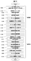
図11は実施例2のスキャン範囲設定のための処理フローチャートである。図11中のステップS101~S114は実施例1と同様である。以下、実施例1の処理フローと異なる箇所のみ説明し、同じ箇所の説明は省略する。
(ステップS201)寝台高さと画像内の被検者の倍率マップを作成
このステップでは、寝台の高さと画像倍率とを対応付けたマップを検査前に作成する。
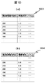
前述したように、被検者に照射されるX線最大幅は寝台の高さによって異なるため、画像倍率は寝台が低い方が小さくなり、高い方が大きくなる。例えば、図10は寝台の高さが200mmの時の倍率を1.0とした時の、寝台の高さと画像倍率を対応付けたマップの例である。同図の(a)のマップ1001はX線管球101が寝台の上側にある場合、同図の(b)のマップ1002はX線管球101が寝台の下側にある場合に対応している。同図に示すように、X線管球101が寝台105の上側にある場合は寝台の高さが高くなるに従い画像倍率は大きく、下側にある場合は画像倍率を小さくする。
このステップでは、寝台の高さと画像倍率とを対応付けたマップを検査前に作成する。
前述したように、被検者に照射されるX線最大幅は寝台の高さによって異なるため、画像倍率は寝台が低い方が小さくなり、高い方が大きくなる。例えば、図10は寝台の高さが200mmの時の倍率を1.0とした時の、寝台の高さと画像倍率を対応付けたマップの例である。同図の(a)のマップ1001はX線管球101が寝台の上側にある場合、同図の(b)のマップ1002はX線管球101が寝台の下側にある場合に対応している。同図に示すように、X線管球101が寝台105の上側にある場合は寝台の高さが高くなるに従い画像倍率は大きく、下側にある場合は画像倍率を小さくする。
(ステップS202)マップから寝台高さに対応する画像倍率を選択
このステップでは、位置決め画像撮影時の寝台105の高さをステップS109で取得しておき、取得した寝台の高さに応じた画像倍率を、ステップS201で作成したマップから選択する。
このステップでは、位置決め画像撮影時の寝台105の高さをステップS109で取得しておき、取得した寝台の高さに応じた画像倍率を、ステップS201で作成したマップから選択する。
(ステップS203)画像倍率を使用してマージン値を計算
このステップでは、ステップS202で選択した画像倍率に従って、範囲設定パターンに設定してあるマージン値を調整する。例えば、範囲設定パターンA(マージン値:全て20)が設定されている検査プロトコルで、図10の(a)のマップ1001を使用し、位置決め画像撮影時の寝台の高さが190mmだった場合、マージン値を18に調整する。それ以降は実施例1と同様の処理フローが実行される。
このステップでは、ステップS202で選択した画像倍率に従って、範囲設定パターンに設定してあるマージン値を調整する。例えば、範囲設定パターンA(マージン値:全て20)が設定されている検査プロトコルで、図10の(a)のマップ1001を使用し、位置決め画像撮影時の寝台の高さが190mmだった場合、マージン値を18に調整する。それ以降は実施例1と同様の処理フローが実行される。
本実施例によれば、撮影時の寝台の高さに依らず、操作者の所望するスキャン範囲が自動で設定できるため、スキャン範囲設定の不正確性が更に改善される。
次に、実施例3について図12及び図13を用いて説明する。本実施例は、記憶部に被検者の心電波形と心臓の動きを対応付けるマップを記憶しておき、スキャン範囲自動設定部は、位置決め画像の撮影の際に取得した被検者の心電波形に基づきマップを参照し、範囲設定パターンに記憶されているマージン値を調整してスキャン範囲を設定する構成の実施例である。
検査対象となる体の部位の中には、常に動いている部位と、ほとんど動かない、あるいは、全く動かない部位がある。検査対象が常に動いている臓器の場合、位置決め画像撮影時とは臓器の位置や大きさが異なることがあり、設定されたスキャン範囲から検査対象が本撮影中にはみ出すと、診断に必要な画像が取得できない。そのため、臓器の位置や大ききが異なる場合でも検査対象が含まれるようにスキャン範囲を設定する必要がある。
そこで、実施例3では、動きのある臓器が検査対象である場合に、臓器の変動位置や大きさの変位を推定し、それらの影響を加味してマージン値を計算する。例えば、検査対象が心臓の場合は、心電同期撮影が一般的に用いられる。心電同期撮影法には、被検者の心電図を取得し参照しながら所望の心拍位相でのみX線を照射する方法(以下、プロスペクティブスキャン)と、被検者の心電波形と投影データとを同時に取得するヘリカル撮影を行う方法(以下、レトロスペクティブスキャン)がある。プロスペクティブスキャンの場合は、撮影するタイミングを心電図に対して指定するため、指定したタイミングでの位置や大きさに応じてマージン値を調整する。レトロスペクティブスキャンの場合は、撮影中に取り得る変動位置・最大の大きさを推定し、マージン値を調整する。そのために、心電波形と心臓の位置・大きさなどの対応付けを予め行っておく。
すなわち、実施例3と先の実施例と異なる点は、心電波形と心臓の動き(変動位置、大きさの変位)を対応付けるマップを予め作成しておき、位置決め画像撮影と同時に被検者の心電波形を取得し、マップを参照して検査対象が含まれるようなスキャン範囲となるようにマージン値を調整し、スキャン範囲として設定する点である。
図13は実施例3のスキャン範囲設定のための処理フローチャートである。ここでは実施例3の一例として、検査対象が心臓であり、撮影方法がレトロスペクティブスキャンの場合について説明する。図13中のステップS101~S114は先の実施例と同様である。以下、先の実施例と異なる箇所のみ説明し、同じ箇所の説明は省略する。
(ステップS301)心拍1周期における心臓の位置・大きさのマップ作成
このステップでは、一般的な心電波形に基づいて、心拍一周期分の各心拍位相に対する心臓の位置・大きさを対応付けたマップを検査前に作成する。例えば、図12は心電波形1202と心臓の大きさ1201を対応付けた例であり、心拍一周期分の心拍位相を時間t1~t7に区切り、心臓の大きさ1201が最小時(ここではt5の時)の大きさに対する割合のマップ1203を作成した例である。
このステップでは、一般的な心電波形に基づいて、心拍一周期分の各心拍位相に対する心臓の位置・大きさを対応付けたマップを検査前に作成する。例えば、図12は心電波形1202と心臓の大きさ1201を対応付けた例であり、心拍一周期分の心拍位相を時間t1~t7に区切り、心臓の大きさ1201が最小時(ここではt5の時)の大きさに対する割合のマップ1203を作成した例である。
(ステップS109)位置決め画像撮影
本実施例では、位置決め画像取得時に、心拍位相などの心電情報を取得する。
本実施例では、位置決め画像取得時に、心拍位相などの心電情報を取得する。
(ステップS302)位置決め画像撮影時の心拍位相を推定
このステップでは、ステップS109で取得した心電情報を元に、位置決め画像撮影時の心拍位相(心拍一周期の内のどの位置か)を推定する。
このステップでは、ステップS109で取得した心電情報を元に、位置決め画像撮影時の心拍位相(心拍一周期の内のどの位置か)を推定する。
(ステップS303)心臓の位置・大きさを推定
このステップでは、ステップS302で推定した心拍位相を元に、撮影時に取り得る心臓の変動位置・最大の大きさを推定する。例えば、心臓の大きさについては、図12に示すようなマップを使用し、位置決め画像撮影時の心拍位相における大きさを元に、最大の大きさとなるt3の心拍位相での大きさを求める。例えば、位置決め画像撮影時の心拍位相が図12中のt4であり、位置決め画像上の心臓の大きさが130mmである場合、撮影時に取り得る心臓の大きさは最大約141.5mmとなる。
このステップでは、ステップS302で推定した心拍位相を元に、撮影時に取り得る心臓の変動位置・最大の大きさを推定する。例えば、心臓の大きさについては、図12に示すようなマップを使用し、位置決め画像撮影時の心拍位相における大きさを元に、最大の大きさとなるt3の心拍位相での大きさを求める。例えば、位置決め画像撮影時の心拍位相が図12中のt4であり、位置決め画像上の心臓の大きさが130mmである場合、撮影時に取り得る心臓の大きさは最大約141.5mmとなる。
(ステップS304)マージン値を計算
このステップでは、撮影時の心臓の位置・大きさがステップS303で推定した心臓の変動位置・最大の大きさであっても、範囲設定パターンに設定したマージン値を保つように、マージン値を計算する。つまり、位置決め画像に対する抽出領域範囲と、ステップS303で推定した心臓の変動位置・最大の大きさの場合での範囲との差分だけ、範囲設定パターンに設定してあったマージン値に加える。例えば、範囲設定パターンのマージン値が20、位置決め画像に対する抽出領域範囲が130、最大時の大きさが140である場合、スキャン範囲を160で設定する。すなわち、マージン値を30に調整する。
このステップでは、撮影時の心臓の位置・大きさがステップS303で推定した心臓の変動位置・最大の大きさであっても、範囲設定パターンに設定したマージン値を保つように、マージン値を計算する。つまり、位置決め画像に対する抽出領域範囲と、ステップS303で推定した心臓の変動位置・最大の大きさの場合での範囲との差分だけ、範囲設定パターンに設定してあったマージン値に加える。例えば、範囲設定パターンのマージン値が20、位置決め画像に対する抽出領域範囲が130、最大時の大きさが140である場合、スキャン範囲を160で設定する。すなわち、マージン値を30に調整する。
ここでは検査対象が心臓である場合について説明したが、他の検査対象であっても同様の方法が適用できる。例えば、検査対象が肺野・横隔膜の場合は、呼吸のタイミングで位置や大きさが変わる。位置決め画像撮影及び本撮影は多くの場合、息止めした状態で行われ、検査対象の位置や大きさは両撮影時で一致する。しかし、息止めが難しい被検者の場合には検査対象の位置や大きさが両撮影時で一致するとは限らない。そこで、呼吸波形などと肺野・横隔膜の位置・大きさの対応付けを行ってマップを作成しておき、位置決め画像撮影時の呼吸タイミングから臓器の取り得る位置・大きさを推定し、マージン値を調整する。
本実施例によれば、検査対象の部位が常に動いている臓器のような場合であっても操作者の所望する、かつ、診断に必要な画像を取得できるようなスキャン範囲を設定できるため、スキャン範囲設定の不正確性が更に改善される。
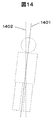
次に、実施例4について図14~図17を用いて説明する。本実施例は、スキャン範囲自動設定部は、位置決め画像より、スキャン中心線に対する被検者の体軸の傾きθを算出し、位置決め画像をθ回転させた画像(以下、θ回転画像)を生成し、θ回転画像に対して抽出領域範囲を生成し、θ回転画像に対するスキャン範囲(以下、θ回転スキャン範囲)を算出し、当該θ回転スキャン範囲を-θ回転させた値をスキャン範囲として設定する構成の実施例である。
すなわち、本実施例では、先の実施例の内容に加え、被検者が寝台に真っ直ぐ寝られない場合、すなわち、図14に示すように、被検者の体軸1401がスキャン中心線1402に対して傾いている場合においても、スキャン範囲を自動的に設定することが可能な構成を説明する。
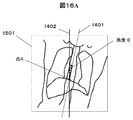
被検者の体軸1401がスキャン中心線1402に対して傾いている場合、位置決め画像上では被検者が斜めに写るため、図15に示すように、位置決め画像1501に対する抽出領域範囲1502及び、抽出領域範囲とマージン値の範囲1503は、本来設定したいスキャン範囲1504とはならず、スキャンが不足する部分及び、スキャンが不要な部分が生じる。そのため、被検者の傾き具合に合わせて抽出領域範囲及びスキャン範囲を設定する必要がある。そこで、位置決め画像から被検者の傾き具合を求め、被検者が傾いていない場合での抽出領域範囲及びスキャン範囲を求め、求めたスキャン範囲を被検者の傾き分だけ傾け、スキャン範囲として設定する。
すなわち、上述の実施例と異なる点は、図16Aに示すように、位置決め画像1501より、スキャン中心線1402に対する被検者の体軸1401の傾きの角度θ(反時計回りを正とする)を算出し、図16Bに示すように、位置決め画像1501をθ回転させたθ回転画像1601を生成し、このθ回転画像1601に対して抽出領域範囲を生成し、θ回転画像に対するスキャン範囲であるθ回転スキャン範囲1602を算出し、図16Cに示すように、θ回転スキャン範囲1602を-θ回転させた値をスキャン範囲1603として設定する点である。なお、図16Cにおいて、1604はスキャン範囲1603の中心線を示している。
図17は実施例4のスキャン範囲設定のための処理フローチャートである。図17中のステップS101~S114は先の実施例と同様である。以下、先の実施例と異なる箇所のみ説明し、同じ箇所の説明は省略する。
(ステップS401)角度θ・点Aを算出
このステップでは、図16Aに示したように、位置決め画像1501を元に被検者の体軸1401を求め、スキャン中心線1402と被検者の体軸1401とがなす角度θ、及びスキャン中心線と被検者の体軸の交点Aを求める。被検者の体軸1401の求め方は、例えば、位置決め画像のCT値を解析して求めても良いし、寝台やスキャンガントリ部にセンサーやCCDカメラを搭載し被検者のセッティング状態を別で取得して解析しても良いし、その他公知の方法でも良い。
このステップでは、図16Aに示したように、位置決め画像1501を元に被検者の体軸1401を求め、スキャン中心線1402と被検者の体軸1401とがなす角度θ、及びスキャン中心線と被検者の体軸の交点Aを求める。被検者の体軸1401の求め方は、例えば、位置決め画像のCT値を解析して求めても良いし、寝台やスキャンガントリ部にセンサーやCCDカメラを搭載し被検者のセッティング状態を別で取得して解析しても良いし、その他公知の方法でも良い。
(ステップS402)θ回転画像を生成
このステップでは、図16Bに示すような、ステップS109で取得した位置決め画像をθ回転させたθ回転画像1601を生成する。θ回転画像1601は、スキャン中心と被検者の体軸が傾いていない時に撮影した位置決め画像に相当する画像である。回転させる方法は、例えば、以下の式で表現される回転行列を利用する方法がある。以下の数1は、点A(ax,ay)を中心に点B(bx,by)を角度θ回転させた点C(cx,cy)を計算する。
このステップでは、図16Bに示すような、ステップS109で取得した位置決め画像をθ回転させたθ回転画像1601を生成する。θ回転画像1601は、スキャン中心と被検者の体軸が傾いていない時に撮影した位置決め画像に相当する画像である。回転させる方法は、例えば、以下の式で表現される回転行列を利用する方法がある。以下の数1は、点A(ax,ay)を中心に点B(bx,by)を角度θ回転させた点C(cx,cy)を計算する。

なお、回転させる方法は、上記の数1以外の公知の方法でも良い。
(ステップS403、S404)θ回転範囲パラメータを計算
このステップでは、ステップS402で生成したθ回転画像より、θ回転範囲パラメータを計算する。ステップS112及びS113は前記実施例と同様の処理である。ステップS404では、θ回転画像に対する抽出領域範囲に、範囲設定パターンで設定したマージン値を加え、範囲パラメータを算出し、θ回転範囲パラメータとする。
このステップでは、ステップS402で生成したθ回転画像より、θ回転範囲パラメータを計算する。ステップS112及びS113は前記実施例と同様の処理である。ステップS404では、θ回転画像に対する抽出領域範囲に、範囲設定パターンで設定したマージン値を加え、範囲パラメータを算出し、θ回転範囲パラメータとする。
(ステップS405)範囲パラメータを算出
このステップでは、図16Cに示すような、ステップS404で計算したθ回転範囲パラメータを-θ回転させ、範囲パラメータを算出する。回転させる方法は、上記記載の方法でも良いし、その他公知の方法でも良い。
このステップでは、図16Cに示すような、ステップS404で計算したθ回転範囲パラメータを-θ回転させ、範囲パラメータを算出する。回転させる方法は、上記記載の方法でも良いし、その他公知の方法でも良い。
(ステップS114)スキャン範囲として設定
また、上記のステップのように算出したスキャン範囲1603の中心線1604は、図16Cに示すように、スキャン中心線1402に対して傾いている。このようなスキャン範囲1603を設定するためには、例えば、X線照射範囲であれば、コリメータ103を特開2015-59889号公報で提案されているような精細な照射形状を可能とするコリメータとし、図16Cで示すスキャン範囲1603の通りにスキャンしても良いし、画像作成範囲であれば、特に機械的な構成を追加しなくとも良い。
また、上記のステップのように算出したスキャン範囲1603の中心線1604は、図16Cに示すように、スキャン中心線1402に対して傾いている。このようなスキャン範囲1603を設定するためには、例えば、X線照射範囲であれば、コリメータ103を特開2015-59889号公報で提案されているような精細な照射形状を可能とするコリメータとし、図16Cで示すスキャン範囲1603の通りにスキャンしても良いし、画像作成範囲であれば、特に機械的な構成を追加しなくとも良い。
本実施例によれば、スキャン中心に対して被検者の体軸が傾いている場合でも、操作者の所望するスキャン、かつ、データの取得過不足の無い最低限の被曝量となるようなスキャン範囲を設定することが可能となる。
次に、実施例5について図18~図20を用いて説明する。本実施例は、記憶部に、位置決め画像に対する抽出領域範囲のFOV(以下、抽出FOV)と、ビームハードニング(以下、BH)による画像への影響を軽減するための適切なBH補正度合となるような撮影時のFOV(以下、収集FOV)とを対応付けたマップを記憶しておき、スキャン範囲自動設定部は、当該マップを参照して、抽出FOVに応じた収集FOVをスキャン範囲として設定する構成の実施例である。すなわち、本実施例では、上述した実施例の内容に加え、X線CT装置におけるBHによる画像への影響を軽減するためのBH補正が適切となるように、収集FOVを設定する実施例を説明する。
BH補正は、収集FOVと同等の大きさの被検者を想定してCT値を補正するため、図18に示すように、被検者901の大きさに対して設定された収集FOVが適切でない場合、BH補正が適切ではなくなり、CT値のカッピングやキャッピングが生じ、画像に悪影響を及ぼす。
そこで、図19で示すように収集FOVごとにBH補正度合1901が決まっていることを利用し、抽出FOVに応じて、適切なBH補正度合となるような収集FOVの値をスキャン範囲として設定する。すなわち、先の実施例と異なる点は、位置決め画像に対する抽出FOVと、適切なBH補正度合となるような収集FOVとを対応付けたマップを予め作成しておき、抽出FOVに応じた収集FOVをスキャン範囲として設定する点である。
そこで、図19で示すように収集FOVごとにBH補正度合1901が決まっていることを利用し、抽出FOVに応じて、適切なBH補正度合となるような収集FOVの値をスキャン範囲として設定する。すなわち、先の実施例と異なる点は、位置決め画像に対する抽出FOVと、適切なBH補正度合となるような収集FOVとを対応付けたマップを予め作成しておき、抽出FOVに応じた収集FOVをスキャン範囲として設定する点である。
図20は実施例5のスキャン範囲設定のための処理フローチャートである。図20中のステップS101~S114は先の実施例と同様である。以下、先の実施例と異なる箇所のみ説明し、同じ箇所の説明は省略する。
(ステップS501)抽出FOVとBH補正度合が最適となる収集FOVのマップを作成
このステップでは、上述したように、図19で示すように収集FOVごとにBH補正度合1901が決まっていることを利用し、抽出FOVと適切なBH補正度合となるような収集FOVの値とを対応付けたマップを検査前に作成する。
このステップでは、上述したように、図19で示すように収集FOVごとにBH補正度合1901が決まっていることを利用し、抽出FOVと適切なBH補正度合となるような収集FOVの値とを対応付けたマップを検査前に作成する。
(ステップS502)マップから抽出FOVに対応する収集FOVを選択
このステップでは、ステップS501で作成したマップを使用し、S113で生成した抽出領域範囲の抽出FOVに対応する収集FOVを選択する。また、ここで選択した収集FOVをスキャン範囲として設定するが、例えば、本実施例で求めたFOVの値、または、先の実施例の方法で算出したFOVの値のどちらをスキャン範囲として設定するか選択できるような手段を備えさせるようにしても良い。
このステップでは、ステップS501で作成したマップを使用し、S113で生成した抽出領域範囲の抽出FOVに対応する収集FOVを選択する。また、ここで選択した収集FOVをスキャン範囲として設定するが、例えば、本実施例で求めたFOVの値、または、先の実施例の方法で算出したFOVの値のどちらをスキャン範囲として設定するか選択できるような手段を備えさせるようにしても良い。
本実施例によれば、検査対象を確実にスキャン範囲内に入れつつ、適切なビームハードニング補正を行うことができるので、スキャン範囲設定の不正確性と画質が改善される。
次に、実施例6について図21を用いて説明する。本実施例は、スキャン範囲自動設定部は、操作者がスキャン範囲を調整した場合、スキャン範囲を調整した情報であるスキャン範囲調整情報を記憶部に蓄積しておき、次回の検査時には、蓄積したスキャン範囲調整情報を元に最適化したマージン値を使用してスキャン範囲を設定する構成の実施例である。すなわち、本実施例では、先の実施例のようにスキャン範囲を自動で設定した場合においても、操作者がスキャン範囲を手動で調整することがあるため、手動で調整した場合にはスキャン範囲調整情報を順次蓄積しておき、スキャン範囲調整情報を元にマージン値を最適化し、次回以降の検査時には最適化されたマージン値を適用したスキャン範囲を設定する。
図21A、21Bは実施例6のスキャン範囲設定のための事前処理、及び処理フローチャートである。図21B中のステップS101~S114は先の実施例と同様である。以下、先の実施例と異なる箇所のみ説明し、同じ箇所の説明は省略する。まず、図21Aのフローチャートについて説明する。
(ステップS601)スキャン範囲調整情報を蓄積
先の実施例のようにしてスキャン範囲が設定されたのち、操作者がスキャン範囲を手動で調整し、本撮影が行われた後、スキャン範囲調整情報を、記憶装置などに蓄積する。スキャン範囲調整情報とは、例えば、位置決め画像のパターン、被検者の身長・体重、検査対象の部位、心電情報、位置決め画像に対する抽出領域範囲の位置、自動設定したスキャン範囲に対して手動で調整した場所・調整量、各種撮影条件が挙げられるが、これら以外の情報を合わせて蓄積しても良い。
先の実施例のようにしてスキャン範囲が設定されたのち、操作者がスキャン範囲を手動で調整し、本撮影が行われた後、スキャン範囲調整情報を、記憶装置などに蓄積する。スキャン範囲調整情報とは、例えば、位置決め画像のパターン、被検者の身長・体重、検査対象の部位、心電情報、位置決め画像に対する抽出領域範囲の位置、自動設定したスキャン範囲に対して手動で調整した場所・調整量、各種撮影条件が挙げられるが、これら以外の情報を合わせて蓄積しても良い。
(ステップS602)マージン値最適化
このステップでは、ステップS601で蓄積したスキャン範囲調整情報を元に、範囲設定パターンのマージン値を最適化する。最適化する方法として、機械学習プログラムを利用する方法や、その他の公知の方法を使用しても良い。次に、図21Bのフローチャートについて説明する。
このステップでは、ステップS601で蓄積したスキャン範囲調整情報を元に、範囲設定パターンのマージン値を最適化する。最適化する方法として、機械学習プログラムを利用する方法や、その他の公知の方法を使用しても良い。次に、図21Bのフローチャートについて説明する。
(ステップS603)最適化されたマージン値を使用
このステップでは、ステップS113で抽出領域範囲生成後、ステップS602で最適化したマージン値を適用する。また、例えば、最適化されたマージン値、または、前記実施例の方法で算出したマージン値のどちらを適用するか選択できるような手段を備えさせても良い。
このステップでは、ステップS113で抽出領域範囲生成後、ステップS602で最適化したマージン値を適用する。また、例えば、最適化されたマージン値、または、前記実施例の方法で算出したマージン値のどちらを適用するか選択できるような手段を備えさせても良い。
本実施例によれば、病院・ユーザごとに異なるスキャン範囲設定基準に高精度で追従することができ、また、ユーザの経験や技術に起因するスキャン範囲設定の正確性の差が更に解消される。
以上、X線CT装置における本発明の種々の実施例を述べたが、位置決め画像を取得し、位置決め画像を使用した撮影計画操作を有する他の医用画像診断装置または治療機器においても適用可能である。
また、本発明は上記した実施例に限定されるものではなく、様々な変形例が含まれる。
例えば、上記した実施例は本発明のより良い理解のために詳細に説明したのであり、必ずしも説明の全ての構成を備えるものに限定されるものではない。また、ある実施例の構成の一部を他の実施例の構成に置き換えることが可能であり、また、ある実施例の構成に他の実施例の構成を加えることが可能である。また、各実施例の構成の一部について、他の構成の追加・削除・置換をすることが可能である。
例えば、上記した実施例は本発明のより良い理解のために詳細に説明したのであり、必ずしも説明の全ての構成を備えるものに限定されるものではない。また、ある実施例の構成の一部を他の実施例の構成に置き換えることが可能であり、また、ある実施例の構成に他の実施例の構成を加えることが可能である。また、各実施例の構成の一部について、他の構成の追加・削除・置換をすることが可能である。
更に、上述した各構成、機能、システム制御装置、画像演算装置等は、それらの一部又は全部を実現するプログラムを作成する例を中心に説明したが、それらの一部又は全部を例えば集積回路で設計する等によりハードウェアで実現しても良いことは言うまでもない。すなわち、処理部の全部または一部の機能は、プログラムに代え、例えば、ASIC(Application Specific Integrated Circuit)、FPGA(Field Programmable Gate Array)などの集積回路などにより実現してもよい。
1 X線CT装置、100 スキャンガントリ部、101 X線管、102 回転円盤、103 コリメータ、104 開口部、105 寝台、106 X線検出器、107 データ収集装置、108 ガントリ制御装置、109 寝台制御装置、110 X線制御装置、120 操作卓、121 入力装置、122 画像演算装置、123 記憶装置、124 システム制御装置、125 表示装置、201、503、601、801、902、1501 位置決め画像、202 自動で設定されるスキャン範囲、203、1504 本来設定したいスキャン範囲、301 鎖骨と肋骨の交点、302 上げた腕と頭の間にできる肩の窪み、501 範囲設定パターン作成画面、502 範囲設定パターン詳細設定部、504、802、803、1502 抽出領域範囲、505 検査時にスキャン範囲として設定される範囲、602 マージン値、701、1001、1002、1203 マップ、901 被検者、1201 心臓の大きさ、1202 心電波形、1401 被検者の体軸、1402 スキャン中心線、1503 抽出領域範囲とマージン値の範囲、1601 θ回転画像、1602 θ回転スキャン範囲、1603 スキャン範囲、1604 スキャン範囲の中心線、1901 ビームハードニング(BH)補正度合
Claims (13)
- 医用画像診断装置であって、
検査対象とマージン値とを対応付けた範囲設定パターンと、検査プロトコルとを紐付けて記憶する記憶部と、
被検者を撮影して得られる位置決め画像を撮影後、検査プロトコルに紐付けされた前記範囲設定パターンに従い、検査時のスキャン範囲を自動設定するスキャン範囲自動設定部と、を備える、
ことを特徴とする医用画像診断装置。 - 請求項1に記載の医用画像診断装置であって、
前記スキャン範囲自動設定部は、検査前において、前記検査対象を含む抽出領域範囲と前記マージン値とから前記範囲設定パターンを作成して、前記記憶部に記憶する、
ことを特徴とする医用画像診断装置。 - 請求項2に記載の医用画像診断装置であって、
前記抽出領域範囲に対する前記マージン値を操作者がGUIを使って任意の幅で入力可能な入力部を備える、
ことを特徴とする医用画像診断装置。 - 請求項3に記載の医用画像診断装置であって、
撮影された前記位置決め画像を表示する表示部を備え、
前記スキャン範囲自動設定部は、前記表示部に前記位置決め画像と、前記入力部から入力される前記マージン値に基づく前記範囲設定パターンを表示するよう制御する、
ことを特徴とする医用画像診断装置。 - 請求項4に記載の医用画像診断装置であって、
前記スキャン範囲自動設定部は、前記表示部に、前記記憶部に記憶された前記範囲設定パターンのリストを表示するよう制御する、
ことを特徴とする医用画像診断装置。 - 請求項1に記載の医用画像診断装置であって、
前記スキャン範囲自動設定部は、
前記位置決め画像から抽出した検査対象に対応する前記マージン値を前記記憶部から読み出し、検査時の前記スキャン範囲を自動設定する、
ことを特徴とする医用画像診断装置。 - 請求項1に記載の医用画像診断装置であって、
前記被検者にX線を照射するX線源と、前記X線源に対向配置され前記被検者を透過したX線を検出するX線検出器と、前記X線源と前記X線検出器を搭載し前記被検者の周囲を回転する回転円盤と、前記被検者に対して少なくとも一方向から前記X線を照射して前記位置決め画像を撮影するよう制御する制御部と、をさらに備え、
前記制御部は、前記スキャン範囲に基づいて、検査時に照射する前記X線の範囲を設定する、
ことを特徴とする医用画像診断装置。 - 請求項7に記載の医用画像診断装置であって、
前記記憶部は、前記被検者を載置する寝台の高さと前記位置決め画像の画像倍率との関係を対応付けたマップを記憶し、
前記スキャン範囲自動設定部は、前記マップを参照し、検査時の前記寝台の高さに応じて、前記範囲設定パターンに記憶されている前記マージン値を調整して前記スキャン範囲を設定する、
ことを特徴とする医用画像診断装置。 - 請求項7に記載の医用画像診断装置であって、
前記記憶部は、前記被検者の心電波形と心臓の動きを対応付けるマップを記憶し、
前記スキャン範囲自動設定部は、前記位置決め画像の撮影の際に取得した前記被検者の心電波形に基づき前記マップを参照し、前記範囲設定パターンに記憶されている前記マージン値を調整して前記スキャン範囲を設定する、
ことを特徴とする医用画像診断装置。 - 請求項7に記載の医用画像診断装置であって、
前記スキャン範囲自動設定部は、前記位置決め画像より、スキャン中心線に対する前記被検者の体軸の傾きθを算出し、前記位置決め画像をθ回転させた画像であるθ回転画像を生成し、前記θ回転画像に対して抽出領域範囲を生成し、前記θ回転画像に対するスキャン範囲であるθ回転スキャン範囲を算出し、当該θ回転スキャン範囲を-θ回転させた値を前記スキャン範囲として設定する、
ことを特徴とする医用画像診断装置。 - 請求項7に記載の医用画像診断装置であって、
前記記憶部は、前記位置決め画像に対する抽出領域範囲のFOVである抽出FOVと、適切なBH補正度合となるような撮影時のFOVである収集FOVとを対応付けたマップを記憶し、
前記スキャン範囲自動設定部は、当該マップを参照して、前記抽出FOVに応じた前記収集FOVを前記スキャン範囲として設定する、
ことを特徴とする医用画像診断装置。 - 請求項7に記載の医用画像診断装置であって、
前記スキャン範囲自動設定部は、操作者が前記スキャン範囲を調整した場合、スキャン範囲調整情報を前記記憶部に蓄積しておき、次回の検査時には、蓄積した前記スキャン範囲調整情報を元に最適化したマージン値を使用して前記スキャン範囲を設定する、
ことを特徴とする医用画像診断装置。 - 記憶部と制御部とを有する医用画像診断装置の画像処理方法であって、
前記記憶部に、検査対象とマージン値とを対応付けた範囲設定パターンと、検査プロトコルとを紐付けて記憶しておき、
前記制御部は、被検者を撮影して得られる位置決め画像を撮影後、検査プロトコルに紐付けされた前記範囲設定パターンに従い、検査時のスキャン範囲を自動設定する、
ことを特徴とする画像処理方法。
Priority Applications (1)
| Application Number | Priority Date | Filing Date | Title |
|---|---|---|---|
| US16/630,611 US11096649B2 (en) | 2017-08-08 | 2018-04-05 | Medical image diagnostic device and image processing method |
Applications Claiming Priority (2)
| Application Number | Priority Date | Filing Date | Title |
|---|---|---|---|
| JP2017153011A JP6875954B2 (ja) | 2017-08-08 | 2017-08-08 | 医用画像診断装置、及び画像処理方法 |
| JP2017-153011 | 2017-08-08 |
Publications (1)
| Publication Number | Publication Date |
|---|---|
| WO2019030975A1 true WO2019030975A1 (ja) | 2019-02-14 |
Family
ID=65271248
Family Applications (1)
| Application Number | Title | Priority Date | Filing Date |
|---|---|---|---|
| PCT/JP2018/014588 WO2019030975A1 (ja) | 2017-08-08 | 2018-04-05 | 医用画像診断装置、及び画像処理方法 |
Country Status (3)
| Country | Link |
|---|---|
| US (1) | US11096649B2 (ja) |
| JP (1) | JP6875954B2 (ja) |
| WO (1) | WO2019030975A1 (ja) |
Cited By (1)
| Publication number | Priority date | Publication date | Assignee | Title |
|---|---|---|---|---|
| CN116958128A (zh) * | 2023-09-18 | 2023-10-27 | 中南大学 | 基于深度学习的医学图像自动定位方法 |
Families Citing this family (2)
| Publication number | Priority date | Publication date | Assignee | Title |
|---|---|---|---|---|
| WO2019167596A1 (ja) * | 2018-03-01 | 2019-09-06 | 富士フイルム株式会社 | 音響波診断装置および音響波診断装置の制御方法 |
| CN110755075B (zh) * | 2019-10-30 | 2023-07-25 | 上海联影医疗科技股份有限公司 | 磁共振成像方法、装置、设备和存储介质 |
Citations (4)
| Publication number | Priority date | Publication date | Assignee | Title |
|---|---|---|---|---|
| JP2012000448A (ja) * | 2010-05-17 | 2012-01-05 | Toshiba Corp | 画像処理装置及びx線ct装置 |
| US20120213326A1 (en) * | 2009-10-22 | 2012-08-23 | Koninklijke Philips Electronics N.V. | Scan parameter policy |
| JP2015213748A (ja) * | 2014-04-21 | 2015-12-03 | 株式会社東芝 | X線コンピュータ断層撮影装置及びスキャン計画設定支援装置 |
| JP2015213749A (ja) * | 2014-04-21 | 2015-12-03 | 株式会社東芝 | X線コンピュータ断層撮影装置及び撮影条件設定支援装置 |
Family Cites Families (3)
| Publication number | Priority date | Publication date | Assignee | Title |
|---|---|---|---|---|
| BR112015003885A2 (pt) * | 2012-08-27 | 2017-07-04 | Koninklijke Philips Nv | equipamento; método; sistema gerador de imagens; elemento de programa de computador para controlar um equipamento; e mídia de leitura por computador |
| CN103892862B (zh) | 2012-12-28 | 2018-12-25 | Ge医疗系统环球技术有限公司 | 用于侦查图像的自动扫描定位装置 |
| TWI606752B (zh) * | 2016-10-28 | 2017-11-21 | Iner Aec | 用於數位x光機的自動曝露控制系統與其方法 |
-
2017
- 2017-08-08 JP JP2017153011A patent/JP6875954B2/ja active Active
-
2018
- 2018-04-05 WO PCT/JP2018/014588 patent/WO2019030975A1/ja active Application Filing
- 2018-04-05 US US16/630,611 patent/US11096649B2/en active Active
Patent Citations (4)
| Publication number | Priority date | Publication date | Assignee | Title |
|---|---|---|---|---|
| US20120213326A1 (en) * | 2009-10-22 | 2012-08-23 | Koninklijke Philips Electronics N.V. | Scan parameter policy |
| JP2012000448A (ja) * | 2010-05-17 | 2012-01-05 | Toshiba Corp | 画像処理装置及びx線ct装置 |
| JP2015213748A (ja) * | 2014-04-21 | 2015-12-03 | 株式会社東芝 | X線コンピュータ断層撮影装置及びスキャン計画設定支援装置 |
| JP2015213749A (ja) * | 2014-04-21 | 2015-12-03 | 株式会社東芝 | X線コンピュータ断層撮影装置及び撮影条件設定支援装置 |
Cited By (2)
| Publication number | Priority date | Publication date | Assignee | Title |
|---|---|---|---|---|
| CN116958128A (zh) * | 2023-09-18 | 2023-10-27 | 中南大学 | 基于深度学习的医学图像自动定位方法 |
| CN116958128B (zh) * | 2023-09-18 | 2023-12-26 | 中南大学 | 基于深度学习的医学图像自动定位方法 |
Also Published As
| Publication number | Publication date |
|---|---|
| US20210077054A1 (en) | 2021-03-18 |
| US11096649B2 (en) | 2021-08-24 |
| JP6875954B2 (ja) | 2021-05-26 |
| JP2019030478A (ja) | 2019-02-28 |
Similar Documents
| Publication | Publication Date | Title |
|---|---|---|
| CN110139607B (zh) | 用于患者扫描设置的方法和系统 | |
| US9795354B2 (en) | Method and apparatus for increasing field of view in cone-beam computerized tomography acquisition | |
| JP4532005B2 (ja) | X線ct装置及びその画像表示方法 | |
| RU2550542C2 (ru) | Способ и устройство для формирования компьютерных томографических изображений с использованием геометрий со смещенным детектором | |
| JP5171215B2 (ja) | X線ct装置 | |
| US11497459B2 (en) | Methods and system for optimizing an imaging scan based on a prior scan | |
| CN104997528A (zh) | X射线计算机断层拍摄装置以及拍摄条件设定辅助装置 | |
| JP6929689B2 (ja) | 医用画像処理装置及び医用画像診断装置 | |
| WO2015137011A1 (ja) | X線ct装置、及び処理装置 | |
| US11403793B2 (en) | X-ray system for the iterative determination of an optimal coordinate transformation between overlapping volumes that have been reconstructed from volume data sets of discretely scanned object areas | |
| JP6906905B2 (ja) | X線診断装置 | |
| CN109419526A (zh) | 用于数字乳房断层合成中的运动评估和校正的方法和系统 | |
| WO2017213150A1 (ja) | X線ct装置 | |
| WO2019030975A1 (ja) | 医用画像診断装置、及び画像処理方法 | |
| JP4429694B2 (ja) | X線ct装置 | |
| JP5179788B2 (ja) | 医用画像診断装置、その制御方法及びプログラム | |
| JP5588697B2 (ja) | X線ct装置 | |
| WO2006090321A1 (en) | Determination of the coverage of a ct scan | |
| JP2005143948A (ja) | X線ct装置 | |
| JP5027909B2 (ja) | X線ct装置 | |
| WO2006085253A2 (en) | Computer tomography apparatus, method of examining an object of interest with a computer tomography apparatus, computer-readable medium and program element | |
| JP2006288739A (ja) | X線ct装置 | |
| JP2017113081A (ja) | X線ct装置及び撮影方法 | |
| JP2013169359A (ja) | X線ct装置 | |
| JP4644292B2 (ja) | X線ct装置とその画像表示方法 |
Legal Events
| Date | Code | Title | Description |
|---|---|---|---|
| 121 | Ep: the epo has been informed by wipo that ep was designated in this application |
Ref document number: 18844413 Country of ref document: EP Kind code of ref document: A1 |
|
| NENP | Non-entry into the national phase |
Ref country code: DE |
|
| 122 | Ep: pct application non-entry in european phase |
Ref document number: 18844413 Country of ref document: EP Kind code of ref document: A1 |