WO2019026431A1 - 紫外線照射装置 - Google Patents
紫外線照射装置 Download PDFInfo
- Publication number
- WO2019026431A1 WO2019026431A1 PCT/JP2018/022533 JP2018022533W WO2019026431A1 WO 2019026431 A1 WO2019026431 A1 WO 2019026431A1 JP 2018022533 W JP2018022533 W JP 2018022533W WO 2019026431 A1 WO2019026431 A1 WO 2019026431A1
- Authority
- WO
- WIPO (PCT)
- Prior art keywords
- ultraviolet light
- light source
- ultraviolet
- irradiation
- rectangular container
- Prior art date
- Legal status (The legal status is an assumption and is not a legal conclusion. Google has not performed a legal analysis and makes no representation as to the accuracy of the status listed.)
- Ceased
Links
Images










Classifications
-
- A—HUMAN NECESSITIES
- A61—MEDICAL OR VETERINARY SCIENCE; HYGIENE
- A61L—METHODS OR APPARATUS FOR STERILISING MATERIALS OR OBJECTS IN GENERAL; DISINFECTION, STERILISATION OR DEODORISATION OF AIR; CHEMICAL ASPECTS OF BANDAGES, DRESSINGS, ABSORBENT PADS OR SURGICAL ARTICLES; MATERIALS FOR BANDAGES, DRESSINGS, ABSORBENT PADS OR SURGICAL ARTICLES
- A61L2/00—Disinfection or sterilisation of materials or objects, in general; Accessories therefor
- A61L2/02—Disinfection or sterilisation of materials or objects, in general; Accessories therefor using physical processes
- A61L2/08—Radiation
- A61L2/10—Ultraviolet [UV] radiation
-
- B—PERFORMING OPERATIONS; TRANSPORTING
- B65—CONVEYING; PACKING; STORING; HANDLING THIN OR FILAMENTARY MATERIAL
- B65B—MACHINES, APPARATUS OR DEVICES FOR, OR METHODS OF, PACKAGING ARTICLES OR MATERIALS; UNPACKING
- B65B55/00—Preserving, protecting or purifying packages or package contents in association with packaging
- B65B55/02—Sterilising, e.g. of complete packages
- B65B55/04—Sterilising wrappers or receptacles prior to, or during, packaging
-
- B—PERFORMING OPERATIONS; TRANSPORTING
- B65—CONVEYING; PACKING; STORING; HANDLING THIN OR FILAMENTARY MATERIAL
- B65B—MACHINES, APPARATUS OR DEVICES FOR, OR METHODS OF, PACKAGING ARTICLES OR MATERIALS; UNPACKING
- B65B55/00—Preserving, protecting or purifying packages or package contents in association with packaging
- B65B55/02—Sterilising, e.g. of complete packages
- B65B55/04—Sterilising wrappers or receptacles prior to, or during, packaging
- B65B55/08—Sterilising wrappers or receptacles prior to, or during, packaging by irradiation
Definitions
- the present invention relates to an ultraviolet irradiation device for sterilizing the inner surface of a sterilization object such as a container by irradiation with ultraviolet light.
- an ultraviolet irradiation device for irradiating the container with ultraviolet light.
- the ultraviolet irradiation device has the advantage that it is difficult to deteriorate the container etc. to be sterilized compared with the gamma ray irradiation device and the electron beam irradiation device which are the same dry sterilization device, but the irradiation time is slightly longer due to sterilization. It has the disadvantage of As a conventional ultraviolet irradiation device, as shown in FIG. 23, one in which ultraviolet light sources 102 are arranged at intervals of 90 ° around a light source support 103 having a circular cross section has been proposed (for example, patent documents 1).
- the ultraviolet irradiation device described in Patent Document 1 targets the inner surface of the preform P shown in FIG. 23 for sterilization
- the circular inner surface of the preform P has an uneven distance with the ultraviolet light source 102. Therefore, the ultraviolet rays irradiated also become uneven.
- the inner surface of the rectangular container 90 shown in FIG. 24 is to be sterilized
- the inner surface is extremely uneven in the distance to the ultraviolet light source 102, so the irradiated ultraviolet light also becomes extremely uneven.
- the irradiation at the corner 91 which is the farthest point from the point.
- the irradiation amount of the ultraviolet light is set based on the place where the irradiation is the smallest, so if the irradiation of the ultraviolet light is extremely nonuniform on the inner surface of the container, the irradiation time becomes long. Also, various problems occur, such as the occurrence of extra illumination.
- an object of this invention is to provide the ultraviolet irradiation device which can irradiate an ultraviolet-ray more uniformly.
- the ultraviolet irradiation device concerning the 1st invention is an ultraviolet irradiation device which is inserted in the inside of a square container which has a corner, and sterilizes the inner surface of the square container concerned by irradiation of an ultraviolet ray.
- An ultraviolet light source having a portion which is not easily irradiated with the ultraviolet light and a number of cold spots which are the corner portions in the rectangular container;
- the cold spot is provided with an irradiation amount increasing mechanism for increasing the irradiation of the ultraviolet light from the ultraviolet light source.
- the irradiation amount increasing mechanism in the ultraviolet irradiation device according to the first aspect is the ultraviolet light source closest to the cold spot in the rectangular container than the other ultraviolet light sources. It is a power control unit that supplies high power.
- the irradiation amount increasing mechanism in the ultraviolet irradiation device according to the first or second invention is an ultraviolet light source closest to a cold spot in the rectangular container. Is an angle adjustment unit which makes the irradiation center of the ultraviolet light from the light hits the cold spot.
- the irradiation dose increasing mechanism in the ultraviolet irradiation apparatus according to the first or second invention is an ultraviolet light source closest to a cold spot in the rectangular container, It is a protrusion which makes the inside of a square-shaped container approach rather than an ultraviolet light source.
- the irradiation amount increasing mechanism in the ultraviolet irradiation device according to the first invention is: A power control unit that supplies lower power to the ultraviolet light source closest to the cold spot in the rectangular vessel than the other ultraviolet light sources; And / or an angle adjustment unit that makes the ultraviolet light source closest to the cold spot in the rectangular container the angle at which the irradiation center of the ultraviolet light from these ultraviolet light sources strikes the cold spot A protrusion that brings the UV light source closest to the cold spot in the rectangular vessel closer to the inside of the rectangular vessel than other UV light sources, It is.
- the rectangular container in the ultraviolet irradiation apparatus according to the first or second aspect of the present invention is configured in a rectangular shape so that the paper partially overlaps.
- the step formed on the paper is also a cold spot,
- the irradiation amount increasing mechanism increases the irradiation of the ultraviolet light from the ultraviolet light source also on the step.
- An ultraviolet irradiation apparatus is the ultraviolet irradiation apparatus according to the first or second aspect, wherein ultraviolet rays are emitted sequentially from the ultraviolet light source inserted into the inside of the rectangular container, And / or an ON / OFF control unit for stopping the irradiation of the ultraviolet light sequentially from the ultraviolet light which has been withdrawn to the outside of the rectangular container.
- An ultraviolet irradiation apparatus is the ultraviolet irradiation apparatus according to the first or second aspect, wherein the ultraviolet light source is inserted into and removed from the inside of the rectangular container. Equipped with a speed control unit to control The speed control unit controls the speed of insertion of the ultraviolet light source after the ultraviolet light source starts to be inserted into the interior of the rectangular container and / or the ultraviolet light source starts to be withdrawn outside the rectangular container. And the rate of insertion and exit during switching of the UV light source from the insertion to the exit.
- the ultraviolet light irradiated to the cold spot of the rectangular container is increased by the irradiation amount increasing mechanism, so that the inner surface of the rectangular container can be irradiated with the ultraviolet light more uniformly.
- FIG. 2 is a cross-sectional view taken along the line AA of FIG. 1; It is a cross-sectional view which shows the ultraviolet irradiation device which concerns on Embodiment 2 of this invention, and the square container which is the object of the sterilization. It is a cross-sectional view which shows the ultraviolet irradiation device which concerns on Embodiment 3 of this invention, and the square container which is the object of the sterilization.
- FIG. 14 It is a longitudinal cross-sectional view which shows the paper pack of the gable top which can attach a cap which can be mounted
- sectional drawing which shows the foil which seals a straw hole as a level
- sectional drawing which shows the other example of an angle adjustment part.
- FIG. 18 from the Y direction. It is the figure which looked at FIG. 18 from the X direction. It is a figure corresponding to FIG. 19 in case an angle adjustment part is an ultraviolet-ray reflection film. It is a figure corresponding to Drawing 12 at the time of adopting a lens of special shape. It is a cross-sectional view which shows the conventional ultraviolet irradiation device and the preform which is the object of the sterilization. It is a cross-sectional view which shows the state which applied the conventional ultraviolet irradiation device to the square-shaped container.
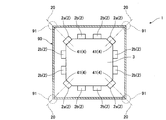
- this ultraviolet irradiation device 1 is inserted into the inside of a rectangular container 90 having a corner 91, and the inner surface of the rectangular container 90 is sterilized by the irradiation of ultraviolet light.
- the square container 90 may have a corner 91, and as an example, a square container 90 having a square cross section is shown in FIGS. 1 and 2.
- the rectangular container may be a triangle or a polygon having five or more sides in cross section.
- the cross section has a corner at the boundary between the bottom and the side. Is not limited to polygons.
- the rectangular container 90 is described as having a square cross section.
- the said ultraviolet irradiation device 1 is equipped with 12 ultraviolet light sources 2 (2a, 2b) by cross sectional view.
- the number (12) of the ultraviolet light sources 2 in cross-sectional view is designed to be larger than the number (4) of the corner portions 91 in cross-sectional view of the rectangular container 90. That is, the number of the ultraviolet light sources 2 in the cross sectional view is not limited to twelve. It is sufficient if the number is equal to or more than the number in the cross sectional view of the rectangular container 90.
- the ultraviolet light source 2 is disposed around the outer periphery of the light source support 3 provided in the ultraviolet irradiation device 1 so as to irradiate the inner surface of the rectangular container 90 with ultraviolet light.
- a portion to which ultraviolet rays are not easily irradiated is a cold spot.
- a portion is only the corner 91 in the example shown in FIGS. 1 and 2.
- the rectangular container 90 has a portion which is difficult to be irradiated with ultraviolet rays, such as unevenness, in addition to the corner portion 91, such a portion also becomes a cold spot.
- the ultraviolet irradiation device 1 includes an irradiation amount increasing mechanism 4 for increasing the irradiation of the ultraviolet light from the ultraviolet light source 2a at the corner portion 91 which is a cold spot. That is, the irradiation amount increasing mechanism 4 is intended to increase the ultraviolet light irradiated to the cold spot and to irradiate the inner surface of the rectangular container 90 with the ultraviolet light more uniformly than the conventional ultraviolet irradiation device.
- the irradiation amount increasing mechanism 4 according to the first embodiment is the four closest to the cold spots (four corners 91 in the example of FIGS. 1 and 2) in the rectangular container 90.
- the inclination part 41 (an example of an angle adjustment part) which makes the ultraviolet light source 2a the angle which the irradiation center 20 of the ultraviolet-ray from these ultraviolet light sources 2a hits the said cold spot. Since these inclined portions 41 are formed on the light source support 3, as shown in FIG. 2, the light source support 3 has a shape in which four corners in a quadrangle in a cross sectional view are cut off by an isosceles right triangle, That is, it is octagonal. A portion (specifically, the base of the isosceles right triangle) in which the four corners of the quadrilateral are cut off is the inclined portion 41, and the ultraviolet light source 2a is disposed in each of the four inclined portions 41. The irradiation center 20 of the ultraviolet light source 2a disposed in the inclined portion 41 is directed to a corner portion 91 (not limited to a precise angle but including a realistic error).
- the corner portion 91 which is a cold spot of the rectangular container 90 by the inclined portion 41 (an example of the angle adjustment unit) which is the irradiation amount increasing mechanism 4. Since the ultraviolet radiation to be irradiated is increased, the inner surface of the rectangular container 90 can be irradiated with the ultraviolet radiation more uniformly.
- the ultraviolet irradiation device 1 according to the second embodiment is different from the ultraviolet irradiation device 1 according to the first embodiment in the irradiation amount increasing mechanism 4.
- the following description will be given focusing on the irradiation amount increasing mechanism 4 different from the first embodiment, and the same components as those of the first embodiment are denoted by the same reference numerals and the description thereof will be omitted.
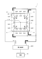
- the irradiation amount increasing mechanism 4 is, as shown in FIG. 3, an ultraviolet light source 2a closest to a cold spot (in the example of FIG. 3, four corner portions 91) as shown in FIG.
- the power control unit 42 supplies power higher than that of the other ultraviolet light sources 2 b from the power supply 10.
- the output of the ultraviolet light from the ultraviolet light source 2a closest to the cold spot is higher than the output from the other ultraviolet light sources 2b. For this reason, the ultraviolet light irradiated to the corner portion 91 which is a cold spot of the rectangular container 90 is increased.
- the power control unit 42 outputs the output of the ultraviolet light from the ultraviolet light source 2a closest to the cold spot and the output of the ultraviolet light from the other ultraviolet light source 2b so that the ultraviolet light irradiated to the inner surface of the rectangular container 90 becomes more uniform. Control the difference between
- the ultraviolet light irradiated to the cold spot 91 of the rectangular container 90 is increased by the power control unit 42 which is the irradiation amount increasing mechanism 4. Therefore, the inner surface of the rectangular container 90 can be irradiated with ultraviolet light more uniformly.
- the ultraviolet irradiation device 1 according to the third embodiment is different from the ultraviolet irradiation devices 1 according to the first and second embodiments in the irradiation amount increasing mechanism 4.
- the following description will be given focusing on the irradiation amount increasing mechanism 4 different from the first and second embodiments, and the same components as those of the first and second embodiments will be denoted by the same reference numerals and the description thereof will be omitted. .
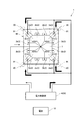
- the irradiation amount increasing mechanism 4 is configured so that the ultraviolet light source 2a closest to the cold spot in the square container 90 (the four corner portions 91 in the example of FIG. 4). These projections 43 allow the inner surface of the rectangular container 90 to be closer to the other ultraviolet light sources 2b. Since these projecting portions 43 are formed on the light source support 3, as shown in FIG. 4, the light source support 3 has the quadrangle 43 smaller than the quadrangle added to the four corners of the quadrangle. It is a shape. These small squares 43 are the projecting portions 43, and the two ultraviolet light sources 2a are disposed on the four projecting portions 43, respectively.
- the protruding portion 43 causes the ultraviolet light source 2a closest to the cold spot to approach the inner surface of the rectangular container 90. For this reason, the ultraviolet light irradiated to the corner portion 91 which is a cold spot of the rectangular container 90 is increased.
- the height of the protrusion 43 is designed so that the ultraviolet light irradiated to the inner surface of the rectangular container 90 is more uniform.
- the ultraviolet light irradiated to the cold spot 91 of the rectangular container 90 is increased by the projecting portion 43 which is the irradiation amount increasing mechanism 4. Therefore, the inner surface of the rectangular container 90 can be irradiated with ultraviolet light more uniformly.
- the inclined portion 41 an example of the angle adjusting portion
- the power control portion 42 and the projecting portion 43 have been described as the irradiation amount increasing mechanism 4, even if some of them are combined. You may combine all or all.
- a combination of the inclined portion 41 (an example of the angle adjusting portion), the power control portion 42 and the protruding portion 43 will be described as the fourth embodiment. Also in the following, the same components as those in the first to third embodiments are given the same reference numerals, and the description thereof will be omitted.
- the irradiation amount increasing mechanism 4 according to the fourth embodiment is, as shown in FIG. 5, an inclined portion 41 (an example of an angle adjusting portion), a power control portion 42 and a protruding portion 43.
- the light source support 3 has a shape in which four corners in a quadrangle are respectively projected toward the corner 91 of the square container 90.
- the tip surfaces of the four protruding portions become the inclined portions 41, and the four protruding portions themselves become the protruding portions 43.
- the ultraviolet light sources 2a are respectively disposed on the tip end surfaces of the four projecting portions.
- the irradiation centers 20 of the ultraviolet light sources 2a disposed at the four protruding points are directed to corner portions 91 (not limited to the exact corners, but include realistic errors).
- the power control unit 42 supplies power higher than that of the other ultraviolet light sources 2 b from the power supply 10 to the ultraviolet light sources 2 a disposed at the four protruding portions.
- the ultraviolet light sources 2a arranged at the four protruding portions are higher than the outputs from the other ultraviolet light sources 2b. For this reason, the ultraviolet light irradiated to the corner portion 91 which is a cold spot of the rectangular container 90 is increased.
- the power control unit 42 controls the output of the ultraviolet light from the ultraviolet light sources 2a and 2b so that the ultraviolet light irradiated to the inner surface of the rectangular container 90 is more uniform, and the height of the protrusion 43 is designed Be done.
- the rectangular container 90 has a bottom
- the rectangular container 90 has a bottom 92 and a side 93, and a corner 91 (not limited to a precise angle, but a realistic error may be generated) at the boundary between the bottom 92 and the side 93. Is included. These corner portions 91 are also cold spots.
- the irradiation amount increasing mechanism 4 increases the irradiation of the ultraviolet light from the ultraviolet light source 2a also to the corner 91 formed by the boundary between the bottom 92 and the side 93 of the rectangular container 90. It is a thing.
- the irradiation amount increasing mechanism 4 shown in FIG. 6 is an inclined portion 41 (an example of an angle adjusting unit) and a power control unit 42.
- the rectangular container 90 is formed by the inclined portion 41 (an example of the angle adjustment unit) which is the irradiation amount increasing mechanism 4, the power control unit 42 and the projecting portion 43. Since the ultraviolet rays irradiated to the corner portion 91 which is a cold spot are increased, the inner surface of the rectangular container 90 can be irradiated with the ultraviolet rays more uniformly.
- an ultraviolet irradiation device 1 according to an example more specifically showing the first to fourth embodiments will be described based on the drawings.
- the following description will be given focusing on the configuration different from the first to fourth embodiments, and the same configuration as the first to fourth embodiments will be assigned the same reference numeral and the description thereof will be omitted.
- the rectangular container 90 whose inner surface is sterilized by the ultraviolet irradiation device 1 according to the present embodiment is a paper pack 90 formed in a rectangular shape so that paper is partially overlapped.
- the paper pack 90 has a step 94 formed by overlapping the sheets, and such a step 94 also becomes a cold spot.
- the paper pack 90 is rectangular in cross section, and has four corner portions 91 (which are cold spots) in cross section.
- the ultraviolet irradiation device 1 comprises an ultraviolet light source 2 (2a, 2b) more than the number of cold spots of the paper pack 90, a light source support 3 on which the ultraviolet light source 2 is disposed, and the light source support And a cooling mechanism 6 for cooling the ultraviolet light source 2 and the vicinity thereof.
- the arrangement of the ultraviolet light sources 2 is four lines in the axial direction of the paper pack 90 and 14 columns in the direction orthogonal to the axial direction of the paper pack 90.
- the ultraviolet light sources 2 are regularly arranged around the outer periphery of the light source support 3 in the row direction and the column direction. Further, since the performance of the ultraviolet light source 2 is significantly reduced when the temperature thereof becomes high, the heat is easily dissipated by the light source support 3 and the heat exchanger 5.
- the light source support 3 in which the ultraviolet light source 2 is disposed, and the heat exchanger 5 connected to the light source support 3 are made of a material having high thermal conductivity (for example, thermal conductivity is higher than that of aluminum Made of metal). Further, the heat exchanger 5 has fins 51 for increasing the surface area in order to effectively dissipate the heat from the ultraviolet light source 2 transmitted through the light source support 3.
- the cooling mechanism 6 cools the ultraviolet light source 2 by, for example, water cooling, and although not shown, a refrigerant circulation path formed along the ultraviolet light source 2 inside the light source support 3 and the refrigerant And a refrigerant circulator that circulates a liquid refrigerant (for example, water) in the circulation path.
- the cooling mechanism 6 is not limited to the liquid cooling type, as long as it can cool the ultraviolet light source 2, and an air cooling type or a Peltier element type may be used.
- FIG. 8 A cross sectional view is shown in FIG. 8 and a longitudinal cross sectional view is shown in FIG. 9 in a state in which the ultraviolet light source 2 is inserted into the inside of the paper pack 90.
- FIG. 8 on the inner surface of the paper pack 90, the paper is folded back as shown in FIG. 9, with a step 94 formed by overlapping and joining the both ends of the paper. There is a step 94 formed by overlapping. Any step 94 is a cold spot together with the corner 91.
- the irradiation amount increasing mechanism 4 is at least the inclined portion 41 and the protruding portion 43 in the present embodiment. For this reason, as shown in FIGS. 8 and 9, the light source support 3 is formed with an inclined portion 41 at a position corresponding to the corner portion 91 of the paper pack 90, and a protrusion at a position corresponding to the step 94. 43 and a slope 41 are formed.
- the UV irradiation device 1 inserts and retracts the UV light source 2 together with the light source support 3 into and out of the paper pack 90, and the UV light source 2 and a control unit 8 for controlling the cooling mechanism 6 and the insertion and withdrawal mechanism 7.
- the insertion and withdrawal mechanism 7 may be any mechanism as long as the ultraviolet light source 2 can be inserted into and withdrawn from the paper pack 90, and for example, the body 71 and the body 71 are disposed. It has an actuator (not shown), a moving part 72 reciprocally moved in the axial direction of the paper pack 90 by this actuator, and a sensor (not shown) for detecting the relative position between the ultraviolet light source 2 and the paper pack 90.
- the control unit 8 controls the cooling of the ultraviolet light source 2 by the cooling mechanism 6, the ON / OFF control unit 82 that controls ON / OFF of the power supplied to the power control unit 42, the ultraviolet light source 2, and the like.
- a cooling control unit 86 and a speed control unit 87 for controlling the speed of the moving unit 72 in the insertion and withdrawal mechanism 7 are provided.
- the control unit 8 also receives data on the relative position between the ultraviolet light source 2 and the paper pack 90 from the sensor of the insertion and withdrawal mechanism 7, and this data is input to the ON / OFF control unit 82 and the speed control unit 87. Shared.
- the ON / OFF control unit 82 turns off the ultraviolet light source 2 in the state outside the paper pack 90, and as shown in FIG. 10 to FIG. 12, the ultraviolet light source 2 inserted inside the paper pack 90. It turns on (is made to irradiate an ultraviolet ray) in order from.
- the ON / OFF control unit 82 may turn OFF (do not irradiate ultraviolet light) sequentially from the ultraviolet light source 2 which has been withdrawn to the outside of the paper pack 90, as shown in the order of FIGS.
- the ON / OFF control unit 82 has a function of sequentially turning on the UV light source 2 inserted from the inside of the paper pack 90 (to emit UV light) and the UV light source 2 withdrawn outside the paper pack 90. You may equip both with the function made to turn off in order (it does not irradiate an ultraviolet-ray).
- the speed control unit 87 is a speed of insertion of the ultraviolet light source 2 from the time when the ultraviolet light source 2 is started to be inserted into the paper pack 90 until all the ultraviolet light sources 2 are inserted into the paper pack 90. It is intended to lower the speed of the withdrawal from the beginning to the exit of the inside as well as the rate of the insertion and the withdrawal during the switching of the ultraviolet light source 2 from the insertion to the exit. In other words, the speed control unit 87 determines the position of the ultraviolet light source 2 near the opening of the paper pack 90 inside the paper pack 90 and the vicinity of the bottom 92 inside the paper pack 90 with the ultraviolet light source 2. The speed is reduced at the position of. This is because, as shown in FIG. 10 to FIG.
- the ON / OFF control unit 82 controls the ultraviolet light source 2 more than other positions. It is because there is little irradiation of ultraviolet rays. Furthermore, as shown in FIG. 9, the bottom portion 92 of the inner surface of the paper pack 90 includes a corner portion 91 (cold spot) formed by the boundary between the bottom portion 92 and the side portion 93 of the paper pack 90; This is because it is necessary to increase the irradiation of the ultraviolet light from the ultraviolet light source 2a because there is a step 94 (cold spot) formed by overlapping the paper of the pack 90 by being folded back.
- the speed control unit 87 directs the paper pack 90 It moves with the moving unit 72.
- the ON / OFF control unit 82 sequentially starts from the ultraviolet light source 2 inserted into the paper pack 90.
- the speed control unit 87 reduces the speed of movement.
- the ultraviolet light source 2 is inserted toward the back of the interior of the paper pack 90 in a state where the speed is returned by the speed control unit 87 while the ultraviolet light source 2 is kept ON by the ON / OFF control unit 82.
- the speed control unit 87 reduces the speed again.
- the movement of the ultraviolet light source 2 is switched from insertion to withdrawal.
- the corner 91 formed by the boundary between the bottom 92 and the side 93 of the paper pack 90 and the paper of the paper pack 90 are formed to overlap by being folded back.
- the step 94 is also sufficiently irradiated with ultraviolet light.
- the speed control unit 87 returns the speed again.
- the ON / OFF control unit 82 starts from the ultraviolet light source 2 withdrawn to the outside of the paper pack 90.
- the speed control unit 87 reduces the speed of movement.
- the power control unit 42 may control the output of each of the ultraviolet light sources 2a and 2b.
- the ultraviolet light source 2 inside the paper pack 90 is turned on by the ON / OFF control unit 82, the excessive irradiation of ultraviolet rays is suppressed, leading to the saving of power, and the generation of the excess heat is suppressed. The deterioration of the performance of the ultraviolet light source 2 can be suppressed.
- the speed of the ultraviolet light source 2 is appropriately controlled by the speed control unit 87, the inner surface can be more uniformly irradiated with ultraviolet light in the axial direction of the paper pack 90.
- the ultraviolet light source 2a closest to one corner 91 is described.
- the ultraviolet light source 2a closest to one corner 91 is two. It may be one.
- the irradiation center 20 obtained by combining the two ultraviolet light sources 2 a is directed to the corner 91.
- the arrangement of the ultraviolet light source 2 in the axial direction of the rectangular container 90 is not described, and in the first, fourth and embodiments, the arrangement of the ultraviolet light source 2 in the axial direction Are illustrated as being identical, but the present invention is not limited thereto.
- the arrangement of the ultraviolet light sources 2 in the axial direction may be staggered. Specifically, it may be arranged as shown in FIG. 2 in a certain cross sectional view, and may be arranged as shown in FIG. 3 in a cross sectional view in a row adjacent thereto.
- the arrangement may be such that only the ultraviolet light source 2a whose irradiation center 20 is directed to the corner 91 in FIG. 2 is left, that is, only the ultraviolet light source 2a corresponding to the cold spot is left.
- the power source 10 supplies power higher than that of the other ultraviolet light source 2b to the ultraviolet light source 2a closest to the cold spot in the rectangular container 90.
- the power supply 10 may supply power lower than that of the other ultraviolet light sources 2b.
- an inclined portion 41 an example of an angle adjusting portion
- a projecting portion 43 as shown in FIG. 5
- an inclined portion 41 an example of an angle adjusting portion
- the ultraviolet light source 2 may be only the ultraviolet light source 2 a disposed in the inclined portion 41 and / or the projecting portion 43 in a certain cross-sectional view.
- the output of the ultraviolet light from the ultraviolet light source 2a closest to the cold spot and the output of the ultraviolet light from the other ultraviolet light sources 2b are made so that the ultraviolet light irradiated to the inner surface of the rectangular container 90 becomes more uniform. Difference is controlled.
- the ultraviolet light sources 2 more than the number of cold spots are disposed in a single light source support 3, but the present invention is not limited thereto.
- the plurality of light source supports 3 are disposed as a whole.
- the number of UV light sources 2 may be greater than the number of cold spots.
- each light source support 3 is provided with a heat exchange body 5, a cooling mechanism 6, an insertion and withdrawal mechanism 7, and a control unit 8 as shown in FIG. Furthermore, the light source support 3 in which only the ultraviolet light source 2a corresponding to the cold spot is disposed is detachable from the heat exchanger 5 shown in FIG. 7 so as to correspond to various rectangular containers 90. It is also good.
- the power control unit 42 may have the function of the ON / OFF control unit 82 as well.
- the unit 82 may have the function of the power control unit 42.
- the ON / OFF control unit 82 controls the duty ratio of the power supplied to the ultraviolet light source 2, that is, the ON time and the OFF time
- the control of the power supplied to the ultraviolet light source 2 is possible by controlling the ratio of
- the ON / OFF control by the ON / OFF control unit 82 may be the same timing for all the ultraviolet light sources 2 or may be different timings.
- the rectangular container 90 and the paper pack 90 having relatively simple shapes have been described to simplify the description, but complex shapes as shown in FIG.
- the square container 90 may be used.
- the square container 90 shown in FIG. 14 is a paper pack 90 which is a gable top (gable roof type) and whose cap 99 can be attached to the spout.
- ultraviolet light is applied to the inner surface by the irradiation amount increasing mechanism 4 (the angle adjustment unit such as the inclined portion 41, the power control unit 42, and / or the projection 43). Can be irradiated more uniformly.
- the step 94 formed in the paper pack 90 the step 94 formed by overlapping the sheets has been described based on FIGS. 8 and 9, but the invention is not limited to such a step 94.
- the step 94 formed at the boundary between the foil 97 (not limited to paper) sealing the straw hole 96 and the periphery thereof is also a cold spot, and the irradiation amount increasing mechanism 4 ( In FIG. 15, the irradiation of the ultraviolet light from the ultraviolet light source 2a is increased by the inclined portion 41 and the projecting portion 43) as an example.
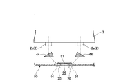
- the angle adjustment unit may be a light transmitting body 44 that refracts the irradiation center 20 of the ultraviolet light from the ultraviolet light source 2 a to the cold spot.
- the material of the light transmitting body 44 may be any material that transmits ultraviolet light, and is, for example, quartz, sapphire, calcium fluoride or a resin transparent to ultraviolet light.
- a lens or the like is adopted as the light transmitting body 44.
- the lens to be employed is in accordance with the shape of a cold spot that emits ultraviolet light.
- the convex lens 45 shown in FIG. 14 Since the irradiated ultraviolet light is uniformly condensed by the convex lens 45, the ultraviolet light corresponding to the shape of the step 94 by the cap 99 is sufficiently irradiated.
- the adopted lens is shown in FIGS.
- the cylindrical lens 46 shown is preferred.
- the cylindrical lens 46 condenses ultraviolet light in one direction (X direction shown in FIGS. 18 and 19), but in the direction orthogonal to the one direction (Y direction shown in FIGS. 18 and 20) Do not collect light. For this reason, as shown in FIG.
- the ultraviolet rays to be irradiated are condensed in the X direction to form a line shape in the Y direction, the ultraviolet rays corresponding to the shape of the step 94 by the foil 97 are sufficiently irradiated.
- an ultraviolet light reflecting film 48 shown in FIG. 21 may be employed.
- the ultraviolet reflection film 48 is disposed to condense the ultraviolet light in the X direction.
- the irradiated ultraviolet light is condensed in the X direction to form a linear shape in the Y direction, so that the ultraviolet light corresponding to the shape of the step 94 by the foil 97 is sufficiently irradiated.
- a cylindrical lens has a semi-hollow (hog-backed) shape, that is, a shape in which two parallel parallel sides of a rectangular parallelepiped are curved.
- a lens having a shape in which only one of these two sides is a curved surface may be employed.
- such a lens 47 is provided in the ultraviolet light source 2b of the row closest to the heat exchanger 5 with the curved surface 47r directed to the heat exchanger 5 side.
- the spread of the ultraviolet light to the original side inserted into the paper pack 90 is suppressed, so that the ultraviolet light leaking from the opening of the paper pack 90 is reduced when the power is not controlled by the ON / OFF control unit 82.
- the angle adjusting unit including the inclined portion 41, the light transmitting body 44 and the ultraviolet light reflecting film 48), the power control unit 42 and the projecting portion 43
- these may only be an example, as long as they increase the irradiation of the ultraviolet light from the ultraviolet light source 2 to the cold spot. That is, the irradiation amount increasing mechanism 4 increases the irradiation of the ultraviolet light to the cold spot as compared with the case without it.
- first to fourth embodiments and the examples are illustrative in all points and not restrictive.
- the scope of the present invention is shown not by the above description but by the claims, and is intended to include all modifications within the meaning and scope equivalent to the claims.
- the configuration other than the configuration described as the first invention in the “means for solving the problems” is an arbitrary configuration, and the configuration is appropriately deleted and changed. It is possible.
Landscapes
- Health & Medical Sciences (AREA)
- General Health & Medical Sciences (AREA)
- Engineering & Computer Science (AREA)
- Mechanical Engineering (AREA)
- Toxicology (AREA)
- Epidemiology (AREA)
- Life Sciences & Earth Sciences (AREA)
- Animal Behavior & Ethology (AREA)
- Public Health (AREA)
- Veterinary Medicine (AREA)
- Apparatus For Disinfection Or Sterilisation (AREA)
Abstract
角部(91)を有する角型容器(90)の内部に挿入されて、角型容器(90)の内面を紫外線の照射により滅菌する紫外線照射装置(1)である。紫外線照射装置(1)は、角部(91)の数よりも多い紫外線光源(2,2a,2b)と、紫外線光源(2,2a,2b)が配置された光源支持体(3)とを備える。紫外線照射装置(1)は、角型容器(90)における角部(91)であるコールドスポットに、紫外線光源(2a)からの紫外線の照射を増大させる照射量増大機構(4)として傾斜部(41)を備える。
Description
本発明は、容器などの滅菌対象物の内面を紫外線の照射により滅菌する紫外線照射装置に関するものである。
飲食品用または医療用の容器を取り扱う企業は、その容器の殺菌が不十分ゆえに食中毒または医療の事故を引き起こすと、社会からの信用が大きく失墜することになる。このため、これらの容器などには、安全性が重要視される先進諸国で、確実な滅菌が必要である。
現在では、容器を確実に滅菌するための装置として、容器に紫外線を照射する紫外線照射装置が採用されている。紫外線照射装置は、同じ乾式滅菌装置であるガンマ線照射装置や電子線照射装置と比べて、滅菌の対象である容器などを劣化させにくいという長所がある反面、滅菌のために照射時間が若干長くなるという短所がある。従来の紫外線照射装置としては、図23に示すように、横断面が円形の光源支持体103の外周囲に、90°間隔で紫外線光源102を配置したものが提案されている(例えば、特許文献1参照)。
ところで、前記特許文献1に記載の紫外線照射装置は図23に示すプリフォームPの内面を滅菌の対象にしているが、このプリフォームPにおける円形の内面は、紫外線光源102との距離が不均一なので、照射される紫外線も不均一になる。特に、図24に示す角型容器90の内面を滅菌の対象にした場合、その内面は、紫外線光源102との距離が著しく不均一なので、照射される紫外線も著しく不均一になり、紫外線光源102から最も離れた箇所である角部91での照射が極めて小さくなる。
容器を紫外線照射装置で滅菌する場合、照射が最も小さい箇所を基準に紫外線の照射量が設定されるので、容器の内面で紫外線の照射が著しく不均一であれば、照射の時間が長くなる、および、余分な照射がされる箇所も生じるなど、様々な問題が発生する。
そこで、本発明は、紫外線をより均一に照射し得る紫外線照射装置を提供することを目的とする。
前記課題を解決するため、第1の発明に係る紫外線照射装置は、角部を有する角型容器の内部に挿入されて、当該角型容器の内面を紫外線の照射により滅菌する紫外線照射装置であって、
前記角型容器における前記紫外線が照射されにくい部分および前記角部であるコールドスポットの数よりも多い紫外線光源と、
前記紫外線光源が配置された光源支持体と、
前記コールドスポットに、前記紫外線光源からの紫外線の照射を増大させる照射量増大機構とを備えるものである。
前記角型容器における前記紫外線が照射されにくい部分および前記角部であるコールドスポットの数よりも多い紫外線光源と、
前記紫外線光源が配置された光源支持体と、
前記コールドスポットに、前記紫外線光源からの紫外線の照射を増大させる照射量増大機構とを備えるものである。
また、第2の発明に係る紫外線照射装置は、第1の発明に係る紫外線照射装置における前記照射量増大機構が、前記角型容器におけるコールドスポットに最も近い紫外線光源に、他の紫外線光源よりも高い電力を供給する電力制御部である。
さらに、第3の発明に係る紫外線照射装置は、第1または第2の発明に係る紫外線照射装置における前記照射量増大機構が、前記角型容器におけるコールドスポットに最も近い紫外線光源を、これら紫外線光源からの紫外線の照射中心が前記コールドスポットに当たる角度にする角度調整部である。
加えて、第4の発明に係る紫外線照射装置は、第1または第2の発明に係る紫外線照射装置における前記照射量増大機構が、前記角型容器におけるコールドスポットに最も近い紫外線光源を、他の紫外線光源よりも角型容器の内部に接近させる突出部である。
また、第5の発明に係る紫外線照射装置は、第1の発明に係る紫外線照射装置における前記照射量増大機構が、
前記角型容器におけるコールドスポットに最も近い紫外線光源に、他の紫外線光源よりも低い電力を供給する電力制御部、並びに、
前記角型容器におけるコールドスポットに最も近い紫外線光源を、これら紫外線光源からの紫外線の照射中心が前記コールドスポットに当たる角度にする角度調整部、および/または、
前記角型容器におけるコールドスポットに最も近い紫外線光源を、他の紫外線光源よりも角型容器の内部に接近させる突出部、
である。
前記角型容器におけるコールドスポットに最も近い紫外線光源に、他の紫外線光源よりも低い電力を供給する電力制御部、並びに、
前記角型容器におけるコールドスポットに最も近い紫外線光源を、これら紫外線光源からの紫外線の照射中心が前記コールドスポットに当たる角度にする角度調整部、および/または、
前記角型容器におけるコールドスポットに最も近い紫外線光源を、他の紫外線光源よりも角型容器の内部に接近させる突出部、
である。
また、第6の発明に係る紫外線照射装置は、第1または第2のいずれかの発明に係る紫外線照射装置における前記角型容器が、紙を一部で重なり合うようにして角型形状に構成した紙パックで、前記紙に形成される段差もコールドスポットであり、
前記照射量増大機構が、前記段差にも紫外線光源からの紫外線の照射を増大させるものである。
前記照射量増大機構が、前記段差にも紫外線光源からの紫外線の照射を増大させるものである。
また、第7の発明に係る紫外線照射装置は、第1または第2のいずれかの発明に係る紫外線照射装置において、前記角型容器の内部に挿入された紫外線光源から順に紫外線を照射させる、および/または、前記角型容器の外部に退出された紫外線から順に紫外線の照射を停止させる、ON/OFF制御部を備えるものである。
また、第8の発明に係る紫外線照射装置は、第1または第2のいずれかの発明に係る紫外線照射装置において、前記紫外線光源を前記角型容器の内部に挿入および当該内部から退出させる速度を制御する速度制御部を備え、
前記速度制御部が、前記紫外線光源が角型容器の内部に挿入され始めてから全て挿入されるまでの間における当該挿入の速度、および/または、前記紫外線光源が角型容器の外部に退出され始めてから全て退出されるまでの間における当該退出の速度、並びに、前記紫外線光源が前記挿入から退出への切換の間における当該挿入および退出の速度、を低くするものである。
前記速度制御部が、前記紫外線光源が角型容器の内部に挿入され始めてから全て挿入されるまでの間における当該挿入の速度、および/または、前記紫外線光源が角型容器の外部に退出され始めてから全て退出されるまでの間における当該退出の速度、並びに、前記紫外線光源が前記挿入から退出への切換の間における当該挿入および退出の速度、を低くするものである。
前記紫外線照射装置によると、照射量増大機構により前記角型容器のコールドスポットに照射される紫外線が増大するので、前記角型容器の内面に紫外線をより均一に照射することができる。
[実施の形態1]
以下、本発明の実施の形態1に係る紫外線照射装置について図1および図2に基づき説明する。
以下、本発明の実施の形態1に係る紫外線照射装置について図1および図2に基づき説明する。
図1に示すように、この紫外線照射装置1は、角部91を有する角型容器90の内部に挿入されて、当該角型容器90の内面を紫外線の照射により滅菌するものである。この角型容器90は角部91を有していればよく、一例として横断面が四角形の角型容器90を図1および図2に示す。勿論、角型容器は、横断面が三角形または五角形以上の多角形でもよい。また、角型容器は、横断面が多角形でなくても(円形であっても)、例えば底部を有する円筒形であれば当該底部と側部との境界に角部を有するので、横断面が多角形に限られない。本実施の形態1では、説明を簡単にするために、角型容器90はその横断面が四角形として説明する。
図2に示すように、前記紫外線照射装置1は、横断面視で12個の紫外線光源2(2a,2b)を備える。これら紫外線光源2の横断面視での個数(12個)は、角型容器90の横断面視での角部91の個数(4個)よりも多く設計される。すなわち、これら紫外線光源2の横断面視での個数は、12個に限られず、角型容器90の横断面視の個数以上であれば足りる。前記紫外線光源2は、図1および図2に示すように、角型容器90の内面に紫外線を照射するように、前記紫外線照射装置1が備える光源支持体3の外周囲に配置されている。
ここで、前記角型容器90において、紫外線が照射されにくい部分がコールドスポットである。このような部分は、図1および図2に示す例だと、前記角部91のみとなる。勿論、前記角型容器90が、角部91の他に、凸凹など紫外線が照射されにくい部分を有するのであれば、そのような部分もコールドスポットとなる。
前記紫外線照射装置1は、コールドスポットである前記角部91に、前記紫外線光源2aからの紫外線の照射を増大させる照射量増大機構4を備える。すなわち、この照射量増大機構4は、コールドスポットに照射される紫外線を増大させて、角型容器90の内面に紫外線を従来の紫外線照射装置よりも均一に照射しようとするものである。具体的に説明すると、本実施の形態1に係る照射量増大機構4は、角型容器90におけるコールドスポット(図1および図2の例だと4個の角部91)に最も近い4個の紫外線光源2aを、これら紫外線光源2aからの紫外線の照射中心20が前記コールドスポットに当たる角度にする傾斜部41(角度調整部の一例である)である。これら傾斜部41は前記光源支持体3に形成されているので、前記光源支持体3は、図2に示すように、横断面視が四角形における4つの角を二等辺直角三角形で切り落とした形状、すなわち、八角形である。前記四角形における4つの角が切り落とされた箇所(具体的には前記二等辺直角三角形の底辺)が前記傾斜部41となり、これら4つの傾斜部41にそれぞれ紫外線光源2aが配置される。前記傾斜部41に配置された紫外線光源2aの照射中心20は、角部91(厳密な角に限られず現実的な誤差を含む)に向けられている。
このように、本実施の形態1に係る紫外線照射装置1によると、照射量増大機構4である傾斜部41(角度調整部の一例)により前記角型容器90のコールドスポットである角部91に照射される紫外線が増大するので、前記角型容器90の内面に紫外線をより均一に照射することができる。
[実施の形態2]
以下、本発明の実施の形態2に係る紫外線照射装置1について図3に基づき説明する。
以下、本発明の実施の形態2に係る紫外線照射装置1について図3に基づき説明する。
本実施の形態2に係る紫外線照射装置1は、前記実施の形態1に係る紫外線照射装置1のうち、照射量増大機構4が異なるものである。以下、前記実施の形態1と異なる照射量増大機構4に着目して説明するとともに、前記実施の形態1と同一の構成については、同一の符号を付してその説明を省略する。
本実施の形態2に係る照射量増大機構4は、図3に示すように、角型容器90におけるコールドスポット(図3の例だと4個の前記角部91)に最も近い紫外線光源2aに、他の紫外線光源2bよりも高い電力を電源10から供給する電力制御部42である。この電力制御部42により、コールドスポットに最も近い紫外線光源2aからの紫外線の出力が、他の紫外線光源2bからの出力よりも上がることになる。このため、前記角型容器90のコールドスポットである角部91に照射される紫外線が増大する。前記電力制御部42は、角型容器90の内面に照射される紫外線がより均一になるように、コールドスポットに最も近い紫外線光源2aからの紫外線の出力と他の紫外線光源2bからの紫外線の出力との差を、制御するものである。
このように、本実施の形態2に係る紫外線照射装置1によると、照射量増大機構4である電力制御部42により前記角型容器90のコールドスポットである角部91に照射される紫外線が増大するので、前記角型容器90の内面に紫外線をより均一に照射することができる。
[実施の形態3]
以下、本発明の実施の形態3に係る紫外線照射装置1について図4に基づき説明する。
以下、本発明の実施の形態3に係る紫外線照射装置1について図4に基づき説明する。
本実施の形態3に係る紫外線照射装置1は、前記実施の形態1および2に係る紫外線照射装置1のうち、照射量増大機構4が異なるものである。以下、前記実施の形態1および2と異なる照射量増大機構4に着目して説明するとともに、前記実施の形態1および2と同一の構成については、同一の符号を付してその説明を省略する。
本実施の形態3に係る照射量増大機構4は、図4に示すように、角型容器90におけるコールドスポット(図4の例だと4個の前記角部91)に最も近い紫外線光源2aを、他の紫外線光源2bよりも角型容器90の内面に接近させる突出部43である。これら突出部43は、前記光源支持体3に形成されているので、前記光源支持体3は、図4に示すように、四角形における4つの角にそれぞれ当該四角形よりも小型の四角形43を付加した形状である。これら小型の四角形43が突出部43となり、これら4つの突出部43にそれぞれ2個の紫外線光源2aが配置される。
前記突出部43により、コールドスポットに最も近い紫外線光源2aが、前記角型容器90の内面に近づくことになる。このため、前記角型容器90のコールドスポットである角部91に照射される紫外線が増大する。前記突出部43の高さは、角型容器90の内面に照射される紫外線がより均一になるように、設計される。
このように、本実施の形態3に係る紫外線照射装置1によると、照射量増大機構4である突出部43により前記角型容器90のコールドスポットである角部91に照射される紫外線が増大するので、前記角型容器90の内面に紫外線をより均一に照射することができる。
[実施の形態4]
以下、本発明の実施の形態4に係る紫外線照射装置1について図5および図6に基づき説明する。
以下、本発明の実施の形態4に係る紫外線照射装置1について図5および図6に基づき説明する。
前記実施の形態1~3では、前記照射量増大機構4として、それぞれ傾斜部41(角度調整部の一例)、電力制御部42および突出部43について説明したが、これらの一部を組み合わせてもよく、または全てを組み合わせてもよい。前記照射量増大機構4が、傾斜部41(角度調整部の一例)、電力制御部42および突出部43を全て組み合わせたものを、本実施の形態4として説明する。以下でも、前記実施の形態1~3と同一の構成については、同一の符号を付してその説明を省略する。
本実施の形態4に係る照射量増大機構4は、図5に示すように、傾斜部41(角度調整部の一例)、電力制御部42および突出部43である。
光源支持体3は、四角形における4つの角をそれぞれ角型容器90の角部91に向けて突出させた形状である。これら突出させた4つの箇所の先端面が傾斜部41となり、突出させた4つの箇所自身が突出部43となる。これら突出させた4つの箇所の先端面にそれぞれ紫外線光源2aが配置される。これら突出させた4つの箇所に配置された紫外線光源2aの照射中心20は、角部91(厳密な角に限られず現実的な誤差を含む)に向けられている。
前記電力制御部42は、前記突出させた4つの箇所に配置された紫外線光源2aに、他の紫外線光源2bよりも高い電力を電源10から供給するものである。この電力制御部42により、前記突出させた4つの箇所に配置された紫外線光源2aが、他の紫外線光源2bからの出力よりも上がることになる。このため、前記角型容器90のコールドスポットである角部91に照射される紫外線が増大する。
前記角型容器90の内面に照射される紫外線がより均一になるように、前記電力制御部42は紫外線光源2a,2bからの紫外線の出力を制御するとともに、前記突出部43の高さが設計される。
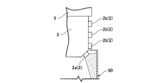
本実施の形態4では、角型容器90が底部を有する場合についても説明する。図6に示すように、前記角型容器90は、底部92および側部93を有し、当該底部92と側部93との境界で角部91(厳密な角に限られず現実的な誤差を含む)が形成されている。これら角部91もコールドスポットである。
本実施の形態4に係る照射量増大機構4は、前記角型容器90の底部92と側部93との境界で形成される角部91にも、紫外線光源2aからの紫外線の照射を増大させるものである。図6に示す照射量増大機構4は、傾斜部41(角度調整部の一例)および電力制御部42である。
このように、本実施の形態4に係る紫外線照射装置1によると、照射量増大機構4である傾斜部41(角度調整部の一例)、電力制御部42および突出部43により前記角型容器90のコールドスポットである角部91に照射される紫外線が増大するので、前記角型容器90の内面に紫外線をより均一に照射することができる。
以下、前記実施の形態1~4をより具体的に示した実施例に係る紫外線照射装置1について図面に基づき説明する。以下、前記実施の形態1~4と異なる構成に着目して説明するとともに、前記実施の形態1~4と同一の構成については、同一の符号を付してその説明を省略する。
図7に示すように、本実施例に係る紫外線照射装置1により内面が滅菌される角型容器90は、紙を一部で重なり合うようにして角型形状に構成した紙パック90である。この紙パック90は、紙が重なり合うことで形成される段差94を有し、このような段差94もコールドスポットになる。また、前記紙パック90は、横断面視が長方形であり、横断面視で4個の角部91(コールドスポットである)を有する。
前記紫外線照射装置1は、前記紙パック90のコールドスポットの数よりも多い紫外線光源2(2a,2b)と、これら紫外線光源2が外周囲に配置される光源支持体3と、この光源支持体3に接続された熱交換体5と、前記紫外線光源2およびその近傍を冷却する冷却機構6とを備える。前記紫外線光源2の配列は、紙パック90の軸方向に4行、および、紙パック90の軸方向に直交する方向に14列である。これら紫外線光源2は、行方向および列方向に、規則的に光源支持体3の外周囲に配置されている。また、紫外線光源2は、高温になると性能が著しく低下するので、前記光源支持体3および熱交換体5により熱を逃がし易くされている。具体的には、紫外線光源2が配置された光源支持体3、および、当該光源支持体3に接続された熱交換体5は、熱伝導率の高い材料(例えば、熱伝導率がアルミニウム以上の金属)で構成されている。また、前記熱交換体5は、前記光源支持体3を介して伝えられた紫外線光源2からの熱を効果的に逃がすために、表面積を増大させるフィン部51を有する。前記冷却機構6は、例えば水冷式により前記紫外線光源2を冷却するものであり、図示しないが、前記光源支持体3の内部で紫外線光源2に沿うように形成された冷媒循環路と、この冷媒循環路に液体の冷媒(例えば水)を循環させる冷媒循環機とを有する。勿論、前記冷却機構6は、前記紫外線光源2を冷却するものであればよいので、液冷式に限られず、空冷式またはペルティエ素子を使用する方式でもよい。
ここで、前記照射量増大機構4について詳細に説明する。前記紙パック90の内部に紫外線光源2が挿入された状態における、横断面視を図8に示し、縦断面視を図9に示す。前記紙パック90の内面には、図8に示すように、前記紙の両端部が重なり合って接合されることで形成される段差94と、図9に示すように、前記紙が折り返されることで重なり合って形成される段差94とがある。いずれの段差94も、角部91とともにコールドスポットである。前記照射量増大機構4は、本実施例だと少なくとも傾斜部41および突出部43である。このため、図8および図9に示すように、前記光源支持体3は、前記紙パック90の角部91に対応する箇所に傾斜部41が形成され、前記段差94に対応する箇所に突出部43および傾斜部41が形成される。
また、前記紫外線照射装置1は、図7に示すように、前記紫外線光源2を前記光源支持体3ごと前記紙パック90の内部に挿入および当該内部から退出させる挿入退出機構7と、前記紫外線光源2、冷却機構6および挿入退出機構7を制御する制御部8とを備える。前記挿入退出機構7は、前記紫外線光源2を前記紙パック90の内部に挿入および当該内部から退出させるものであればよいが、例えば、本体部71と、この本体部71の内部に配置された図示しないアクチュエータと、このアクチュエータにより前記紙パック90の軸方向に往復移動する移動部72と、前記紫外線光源2と紙パック90との相対位置を検出する図示しないセンサとを有する。
前記制御部8は、前記電力制御部42と、前記紫外線光源2に供給される電力のON/OFFを制御するON/OFF制御部82と、前記冷却機構6による紫外線光源2の冷却を制御する冷却制御部86と、前記挿入退出機構7での前記移動部72の速度を制御する速度制御部87とを有する。また、前記制御部8は、前記挿入退出機構7のセンサから前記紫外線光源2と紙パック90との相対位置のデータが入力され、このデータは前記ON/OFF制御部82および速度制御部87で共有される。
前記ON/OFF制御部82は、紙パック90の外部にある状態で紫外線光源2をOFFにするとともに、図10~図12の順に示すように、紙パック90の内部に挿入された紫外線光源2から順にON(紫外線を照射させる)にするものである。また、前記ON/OFF制御部82は、図12~図10の順に示すように、紙パック90の外部に退出された紫外線光源2から順にOFF(紫外線を照射させない)にするものでもよい。勿論、前記ON/OFF制御部82は、紙パック90の内部に挿入された紫外線光源2から順にON(紫外線を照射させる)にする機能と、紙パック90の外部に退出された紫外線光源2から順にOFF(紫外線を照射させない)にする機能との両方を具備してもよい。
前記速度制御部87は、前記紫外線光源2が前記紙パック90の内部に挿入され始めてから全て挿入されるまでの間における当該挿入の速度、および/または、前記紫外線光源2が前記紙パック90の内部から退出され始めてから全て退出されるまでの間における当該退出の速度、並びに、前記紫外線光源2が前記挿入から退出への切換の間における当該挿入および退出の速度、を低くするものである。言い換えれば、前記速度制御部87は、前記紫外線光源2が前記紙パック90の内部における当該紙パック90の開口近傍での位置と、前記紫外線光源2が前記紙パック90の内部における底部92の近傍の位置とで、前記速度を低くするものである。なぜなら、図10~図12に示すように、前記紙パック90の内面における当該紙パック90の開口近傍での位置では、ON/OFF制御部82による制御により、他の位置よりも紫外線光源2からの紫外線の照射が少ないからである。さらに、前記紙パック90の内面における底部92には、図9に示すように、当該紙パック90の底部92と側部93との境界で形成される角部91(コールドスポット)と、前記紙パック90の紙が折り返されることで重なり合って形成される段差94(コールドスポット)とがあるので、紫外線光源2aからの紫外線の照射を増大させる必要があるからである。
次に、本実施例に係る紫外線照射装置1の動作について説明する。
まず、図7に示すように、紙パック90の外部にある状態で紫外線光源2が、ON/OFF制御部82によりOFFにされたままの状態で、速度制御部87により紙パック90に向けて移動部72とともに移動する。
そして、図10~図12の順に示すように、紫外線光源2が紙パック90の内部に挿入されていくと、ON/OFF制御部82により紙パック90の内部に挿入された紫外線光源2から順にONにされていくとともに、速度制御部87により移動の速度が低くされる。紙パック90の内部に挿入された紫外線光源2から順にONにされていくことで、紫外線光源2を紙パック90の外部でONにするという余分な照射が省かれ、これにより、余分な照射により生じる熱の発生も抑えられて紫外線光源2の性能の低下も抑えられる。また、速度が低くされることで、前記紙パック90の内面における当該紙パック90の開口近傍での位置でも、十分に紫外線が照射される。
その後、紫外線光源2が、ON/OFF制御部82によりONにされたままの状態で、速度制御部87により速度を戻した状態で紙パック90の内部の奥に向けて挿入される。紫外線光源2が紙パック90の底部92の近傍まで達すると、速度制御部87により速度が再び低くされる。そして、速度が低くされたまま、紫外線光源2の移動が挿入から退出に切り換えられる。速度が低くされることで、図9に示すように、紙パック90の底部92と側部93との境界で形成される角部91、および紙パック90の紙が折り返されることで重なり合って形成される段差94も、十分に紫外線が照射される。紫外線光源2が紙パック90の底部92の近傍から離れると、速度制御部87により速度が再び戻される。
次いで、図12~図10の順に示すように、紫外線光源2が紙パック90の外部に退出されていくと、ON/OFF制御部82により紙パック90の外部に退出された紫外線光源2から順にOFFにされていくとともに、速度制御部87により移動の速度が低くされる。紙パック90の外部に退出された紫外線光源2から順にOFFにされていくことで、紫外線光源2を紙パック90の外部でONにするという余分な照射が省かれ、これにより、余分な照射により生じる熱の発生も抑えられて紫外線光源2の性能の低下も抑えられる。また、速度が低くされることで、前記紙パック90の内面における当該紙パック90の開口近傍での位置でも、十分に紫外線が照射される。
なお、速度制御部87による紫外線光源2の速度の調整、および、光源支持体3の形状(傾斜部41および突出部43)だけでは紙パック90の内部に紫外線がそれほど均一に照射されないのであれば、電力制御部42により紫外線光源2a,2bごとの出力を制御してもよい。
このように、本実施例に係る紫外線照射装置1によると、照射量増大機構4である傾斜部41、電力制御部42および突出部43により前記紙パック90のコールドスポットである角部91および段差94に照射される紫外線が増大するので、前記紙パック90の内面に紫外線をより均一に照射することができる。
また、ON/OFF制御部82により、紙パック90の内部にある紫外線光源2のみがONになるので、余分な紫外線の照射を抑えて電力の節約につながるとともに、余分な熱の発生を抑えて紫外線光源2の性能の低下を抑えることができる。
さらに、速度制御部87により、紫外線光源2の速度が適切に制御されるので、紙パック90の軸方向においても内面に紫外線をより均一に照射することができる。
ところで、前記実施の形態1では、1個の角部91に最も近い紫外線光源2aを1個として説明したが、図13に示すように、1個の角部91に最も近い紫外線光源2aが2個でもよい。この場合、これら2個の紫外線光源2aを合わせた照射中心20が当該角部91に向けられる。
また、前記実施の形態2および3では紫外線光源2における角型容器90の軸方向での配置を説明せず、前記実施の形態1および4並びに実施例では紫外線光源2の当該軸方向での配置が同一であるとして図示したが、これに限られるものではない。例えば、紫外線光源2の当該軸方向での配置が異なる千鳥配置にしてもよい。具体的には、ある横断面視では図2に示す配置にし、これに隣接する行での横断面視では図3に示す配置としてもよい。さらに、ある横断面視では、図2における角部91に照射中心20を向けた紫外線光源2aのみを残した配置、つまり、コールドスポットに対応した紫外線光源2aのみを残した配置にしてもよい。
加えて、前記実施の形態2および4では、電力制御部42として、角型容器90におけるコールドスポットに最も近い紫外線光源2aに、他の紫外線光源2bよりも高い電力を電源10から供給するものについて説明したが、他の紫外線光源2bよりも低い電力を電源10から供給するものであってもよい。この場合、図5に示すような傾斜部41(角度調整部の一例)および突出部43、図6に示すような傾斜部41(角度調整部の一例)、または、突出部43が必須の構成となる。この場合、紫外線光源2は、ある横断面視が、傾斜部41および/または突出部43に配置された紫外線光源2aのみであってもよい。このような構成により、角型容器90の内面に照射される紫外線がより均一になるように、コールドスポットに最も近い紫外線光源2aからの紫外線の出力と他の紫外線光源2bからの紫外線の出力との差が、制御される。
また、前記実施の形態1~4および実施例では、単一の光源支持体3にコールドスポットの数よりも多い紫外線光源2が配置されたとして説明したが、これに限定されるものではない。例えば、複数の光源支持体3に紫外線光源2が配置され、それぞれの光源支持体3に配置された紫外線光源2がコールドスポットの数より少なくても、複数の光源支持体3全体として、配置された紫外線光源2がコールドスポットの数よりも多ければよい。具体的な例としては、光源支持体3が2つあり、一方の光源支持体3にはコールドスポットに対応する紫外線光源2aのみが配置され(紫外線光源2aはコールドスポットと同数)、他方の光源支持体3にはコールドスポット以外に対応する紫外線光源2bのみが配置された(紫外線光源2bはコールドスポットの数以下)構成でもよい。それぞれの光源支持体3には、図7に示すような、熱交換体5、冷却機構6、挿入退出機構7および制御部8が備えられる。さらに、コールドスポットに対応する紫外線光源2aのみが配置された光源支持体3は、様々な角型容器90に対応可能なように、図7に示す熱交換体5に対して脱着式であってもよい。
また、前記実施例では、電力制御部42とは別個のON/OFF制御部82について説明したが、電力制御部42がON/OFF制御部82の機能も具備してもよく、ON/OFF制御部82が電力制御部42の機能を具備してもよい。ON/OFF制御部82が電力制御部42の機能を具備する例としては、ON/OFF制御部82において、紫外線光源2に供給する電力のデューティー比を制御する、つまりONの時間とOFFの時間との比を制御することで、紫外線光源2に供給する電力の制御が可能になる。ON/OFF制御部82から紫外線光源2に供給する電力を、パルス幅が数msec~数十msecのパルスにすることで、同一の電力を連続的に供給する場合に比べて、滅菌の効率が向上する。なお、ON/OFF制御部82によるONおよびOFFの制御は、全ての紫外線光源2で同一のタイミングとしてもよく、異なるタイミングとしてもよい。
また、前記実施の形態1~4および実施例では、説明を簡単にするために、比較的単純な形状の角型容器90および紙パック90について説明したが、図14に示すような複雑な形状の角型容器90であってもよい。図14に示す角型容器90は、ゲーブルトップ(切妻屋根型)で且つ飲み口にキャップ99が装着可能な紙パック90である。このような複雑な形状の角型容器90であっても、照射量増大機構4(傾斜部41などの角度調整部、電力制御部42、および/または、突出部43)により、その内面に紫外線をより均一に照射することができる。
さらに、前記実施例では、紙パック90に形成される段差94として、紙が重なり合うことで形成される段差94を図8および図9に基づいて説明したが、このような段差94に限られない。例えば、図15に示すように、ストロー穴96を封止する箔97(紙に限られない)とその周囲との境界に形成される段差94も、コールドスポットであり、照射量増大機構4(図15では一例として傾斜部41および突出部43)により紫外線光源2aからの紫外線の照射が増大される。
加えて、角度調整部の一例として、傾斜部41を図2に基づいて説明したが、傾斜部41に限られず、紫外線光源2aからの紫外線の照射中心20がコールドスポットに当たる角度にするものであればよい。例えば、角度調整部は、図16に示すように、紫外線光源2aからの紫外線の照射中心20がコールドスポットに当たる角度に屈折する透光体44であってもよい。
前記透光体44の材質は、紫外線を透過させるものであればよく、例えば、石英、サファイア、フッ化カルシウムまたは紫外線透過性の樹脂などである。また、前記透光体44には、図16に示すようなプリズムの他に、レンズなどが採用される。採用されるレンズは、紫外線を照射するコールドスポットの形状に応じたものである。
例えば、図14に示すような円形状のキャップ99による段差94に紫外線を照射する場合、照射される対象が円形状であるから、採用されるレンズは、図17に示す凸レンズ45が好ましい。この凸レンズ45により、照射される紫外線が均一に集光されるので、キャップ99による段差94の形状に応じた紫外線が十分に照射される。
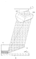
例えば、図16に示すようなストロー穴96を封止する箔97による段差94に紫外線を照射する場合、照射される対象が線形状であるから、採用されるレンズは、図18~図20に示すシリンドリカルレンズ46が好ましい。このシリンドリカルレンズ46は、一方向(図18および図19に示すX方向)には紫外線を集光させるが、当該一方向に直交する方向(図18および図20に示すY方向)には紫外線を集光させない。このため、図18に示すように、照射される紫外線がX方向に集光されてY方向の線形状になるので、箔97による段差94の形状に応じた紫外線が十分に照射される。なお、前記シリンドリカルレンズ46のような透光体44ではなく、図21に示す紫外線反射膜48を採用してもよい。この紫外線反射膜48は、X方向に紫外線を集光させるように配置される。これにより、前記シリンドリカルレンズ46と同様に、照射される紫外線がX方向に集光されてY方向の線形状になるので、箔97による段差94の形状に応じた紫外線が十分に照射される。
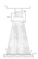
一般的に、シリンドリカルレンズは、かまぼこ形(hog-backed形)であり、つまり直方体の隣り合う平行な2辺を曲面にした形状である。これら2辺のうち1辺のみを曲面にした形状のレンズを採用してもよい。図22に示すように、このようなレンズ47は、前記曲面47rを熱交換体5側に向けた状態で、当該熱交換体5に最も近い行の紫外線光源2bに設けられる。これにより、紙パック90に挿入される元側への紫外線の拡がりが抑えられるので、ON/OFF制御部82で電力を制御しない場合、紙パック90の開口から漏れる紫外線が減少する。
また、前記実施の形態1~4および実施例では、照射量増大機構4として、角度調整部(傾斜部41、透光体44および紫外線反射膜48を含む)、電力制御部42および突出部43について説明したが、これらは一例に過ぎず、コールドスポットに紫外線光源2からの紫外線の照射を増大させるものであればよい。すなわち、照射量増大機構4は、それが無い場合に比べて、コールドスポットへの紫外線の照射を増大させるものである。
また、前記実施の形態1~4および実施例は、全ての点で例示であって制限的なものではない。本発明の範囲は、上述した説明ではなく特許請求の範囲によって示され、特許請求の範囲と均等の意味および範囲内での全ての変更が含まれることが意図される。前記実施の形態1~4および実施例で説明した構成のうち「課題を解決するための手段」での第1の発明として記載した構成以外については、任意の構成であり、適宜削除および変更することが可能である。
Claims (8)
- 角部を有する角型容器の内部に挿入されて、当該角型容器の内面を紫外線の照射により滅菌する紫外線照射装置であって、
前記角型容器における前記紫外線が照射されにくい部分および前記角部であるコールドスポットの数よりも多い紫外線光源と、
前記紫外線光源が配置された光源支持体と、
前記コールドスポットに、前記紫外線光源からの紫外線の照射を増大させる照射量増大機構とを備えることを特徴とする紫外線照射装置。 - 前記照射量増大機構が、前記角型容器におけるコールドスポットに最も近い紫外線光源に、他の紫外線光源よりも高い電力を供給する電力制御部であることを特徴とする請求項1に記載の紫外線照射装置。
- 前記照射量増大機構が、前記角型容器におけるコールドスポットに最も近い紫外線光源を、これら紫外線光源からの紫外線の照射中心が前記コールドスポットに当たる角度にする角度調整部であることを特徴とする請求項1または2に記載の紫外線照射装置。
- 前記照射量増大機構が、前記角型容器におけるコールドスポットに最も近い紫外線光源を、他の紫外線光源よりも角型容器の内部に接近させる突出部であることを特徴とする請求項1または2に記載の紫外線照射装置。
- 前記照射量増大機構が、
前記角型容器におけるコールドスポットに最も近い紫外線光源に、他の紫外線光源よりも低い電力を供給する電力制御部、並びに、
前記角型容器におけるコールドスポットに最も近い紫外線光源を、これら紫外線光源からの紫外線の照射中心が前記コールドスポットに当たる角度にする角度調整部、および/または、
前記角型容器におけるコールドスポットに最も近い紫外線光源を、他の紫外線光源よりも角型容器の内部に接近させる突出部、
であることを特徴とする請求項1に記載の紫外線照射装置。 - 前記角型容器が、紙を一部で重なり合うようにして角型形状に構成した紙パックで、前記紙に形成される段差もコールドスポットであり、
前記照射量増大機構が、前記段差にも紫外線光源からの紫外線の照射を増大させるものであることを特徴とする請求項1または2に記載の紫外線照射装置。 - 前記角型容器の内部に挿入された紫外線光源から順に紫外線を照射させる、および/または、前記角型容器の外部に退出された紫外線から順に紫外線の照射を停止させる、ON/OFF制御部を備えることを特徴とする請求項1または2に記載の紫外線照射装置。
- 前記紫外線光源を前記角型容器の内部に挿入および当該内部から退出させる速度を制御する速度制御部を備え、
前記速度制御部が、前記紫外線光源が角型容器の内部に挿入され始めてから全て挿入されるまでの間における当該挿入の速度、および/または、前記紫外線光源が角型容器の外部に退出され始めてから全て退出されるまでの間における当該退出の速度、並びに、前記紫外線光源が前記挿入から退出への切換の間における当該挿入および退出の速度、を低くするものであることを特徴とする請求項1または2に記載の紫外線照射装置。
Priority Applications (1)
| Application Number | Priority Date | Filing Date | Title |
|---|---|---|---|
| JP2019533941A JP6975789B2 (ja) | 2017-08-02 | 2018-06-13 | 紫外線照射装置 |
Applications Claiming Priority (2)
| Application Number | Priority Date | Filing Date | Title |
|---|---|---|---|
| JP2017-149544 | 2017-08-02 | ||
| JP2017149544 | 2017-08-02 |
Publications (1)
| Publication Number | Publication Date |
|---|---|
| WO2019026431A1 true WO2019026431A1 (ja) | 2019-02-07 |
Family
ID=65233640
Family Applications (1)
| Application Number | Title | Priority Date | Filing Date |
|---|---|---|---|
| PCT/JP2018/022533 Ceased WO2019026431A1 (ja) | 2017-08-02 | 2018-06-13 | 紫外線照射装置 |
Country Status (2)
| Country | Link |
|---|---|
| JP (1) | JP6975789B2 (ja) |
| WO (1) | WO2019026431A1 (ja) |
Cited By (6)
| Publication number | Priority date | Publication date | Assignee | Title |
|---|---|---|---|---|
| WO2021020453A1 (ja) * | 2019-07-30 | 2021-02-04 | 株式会社エンプラス | 殺菌装置 |
| JP2021020043A (ja) * | 2019-07-30 | 2021-02-18 | 株式会社エンプラス | 殺菌装置 |
| JP2021062903A (ja) * | 2019-10-16 | 2021-04-22 | 日立造船株式会社 | 容器の製造装置、製造設備、および製造方法 |
| JP2022018975A (ja) * | 2020-07-16 | 2022-01-27 | 株式会社サンコーデバイス | 紫外線照射装置、紫外線照射制御装置、紫外線照射システム |
| IT202000021169A1 (it) * | 2020-09-08 | 2022-03-08 | Lacchinelli Paolo S A S Di Lacchinelli Ester Alessia & C | Sistema di condizionamento di incarti per alimenti e metodo di realizzazione di incarti sterilizzati per alimenti |
| WO2022239437A1 (ja) * | 2021-05-14 | 2022-11-17 | ウシオ電機株式会社 | 紫外光照射システム |
Families Citing this family (1)
| Publication number | Priority date | Publication date | Assignee | Title |
|---|---|---|---|---|
| CN113261406B (zh) * | 2021-04-30 | 2021-11-09 | 上海鸿余环保科技有限公司 | 一种太赫兹波种子激活处理机 |
Citations (2)
| Publication number | Priority date | Publication date | Assignee | Title |
|---|---|---|---|---|
| JPS58173550A (ja) * | 1982-04-02 | 1983-10-12 | 大日本印刷株式会社 | 殺菌用紫外線照射装置 |
| JP2016078895A (ja) * | 2014-10-17 | 2016-05-16 | 三菱重工食品包装機械株式会社 | 飲料用容器の殺菌装置 |
-
2018
- 2018-06-13 JP JP2019533941A patent/JP6975789B2/ja active Active
- 2018-06-13 WO PCT/JP2018/022533 patent/WO2019026431A1/ja not_active Ceased
Patent Citations (2)
| Publication number | Priority date | Publication date | Assignee | Title |
|---|---|---|---|---|
| JPS58173550A (ja) * | 1982-04-02 | 1983-10-12 | 大日本印刷株式会社 | 殺菌用紫外線照射装置 |
| JP2016078895A (ja) * | 2014-10-17 | 2016-05-16 | 三菱重工食品包装機械株式会社 | 飲料用容器の殺菌装置 |
Cited By (9)
| Publication number | Priority date | Publication date | Assignee | Title |
|---|---|---|---|---|
| WO2021020453A1 (ja) * | 2019-07-30 | 2021-02-04 | 株式会社エンプラス | 殺菌装置 |
| JP2021020043A (ja) * | 2019-07-30 | 2021-02-18 | 株式会社エンプラス | 殺菌装置 |
| JP7761988B2 (ja) | 2019-07-30 | 2025-10-29 | 株式会社エンプラス | 殺菌装置 |
| JP2021062903A (ja) * | 2019-10-16 | 2021-04-22 | 日立造船株式会社 | 容器の製造装置、製造設備、および製造方法 |
| JP7285190B2 (ja) | 2019-10-16 | 2023-06-01 | 日立造船株式会社 | 容器の製造装置、製造設備、および製造方法 |
| JP2022018975A (ja) * | 2020-07-16 | 2022-01-27 | 株式会社サンコーデバイス | 紫外線照射装置、紫外線照射制御装置、紫外線照射システム |
| IT202000021169A1 (it) * | 2020-09-08 | 2022-03-08 | Lacchinelli Paolo S A S Di Lacchinelli Ester Alessia & C | Sistema di condizionamento di incarti per alimenti e metodo di realizzazione di incarti sterilizzati per alimenti |
| EP3964354A1 (en) * | 2020-09-08 | 2022-03-09 | Lacchinelli Paolo S.A.S. di Lacchinelli Ester Alessia & C. | Food wrapping sterilising system and method of making sterilized food wrapping |
| WO2022239437A1 (ja) * | 2021-05-14 | 2022-11-17 | ウシオ電機株式会社 | 紫外光照射システム |
Also Published As
| Publication number | Publication date |
|---|---|
| JPWO2019026431A1 (ja) | 2020-08-20 |
| JP6975789B2 (ja) | 2021-12-01 |
Similar Documents
| Publication | Publication Date | Title |
|---|---|---|
| WO2019026431A1 (ja) | 紫外線照射装置 | |
| US7059731B2 (en) | Compact LED module and projection display adopting the same | |
| JP5661947B2 (ja) | 内側冷却部を備えた蛍光体装置、および、当該蛍光体装置を備えた反射照明装置 | |
| CN101023295B (zh) | 具有半抛物线反射器的发光二极管准直仪部件 | |
| JP6281131B2 (ja) | 光変換装置およびこれを備えた投射型表示装置 | |
| WO2016182024A1 (ja) | 紫外線殺菌装置 | |
| JP7473594B2 (ja) | 集光束uvled紫外線走査方法およびその装置 | |
| EP2964446B1 (en) | Heating system for pet-preforms | |
| JP2013250422A (ja) | 画像投影装置 | |
| KR20170067905A (ko) | 발광 장치 및 관련 프로젝션 시스템 | |
| WO2017098705A1 (ja) | 蛍光体ホイール装置、およびこれを備えた光変換装置、投射型表示装置 | |
| KR102050653B1 (ko) | 발광 다이오드 램프 | |
| JP2009061702A (ja) | 紫外線照射装置 | |
| US12535234B2 (en) | Air sterilization apparatus and air conditioner using same | |
| JP6286862B2 (ja) | プロジェクター | |
| JP7070146B2 (ja) | 光源モジュール、及び光学装置 | |
| JP7169719B2 (ja) | 殺菌方法及び殺菌装置 | |
| JP6846871B2 (ja) | バッフル付き光エンジンフレーム | |
| JP5879792B2 (ja) | 蛍光体層の温度測定方法、光源装置及びプロジェクター | |
| KR20140121525A (ko) | 디스플레이 장치 | |
| JPH03104661A (ja) | 画像記録装置 | |
| US20150099940A1 (en) | Luminaire with tir reflector | |
| CN106678625A (zh) | 一种紫外光源组件及紫外光学系统和紫外印刷装置 | |
| JP5668980B2 (ja) | 発光装置 | |
| TWI666405B (zh) | 發光裝置和發光方法 |
Legal Events
| Date | Code | Title | Description |
|---|---|---|---|
| 121 | Ep: the epo has been informed by wipo that ep was designated in this application |
Ref document number: 18840934 Country of ref document: EP Kind code of ref document: A1 |
|
| ENP | Entry into the national phase |
Ref document number: 2019533941 Country of ref document: JP Kind code of ref document: A |
|
| NENP | Non-entry into the national phase |
Ref country code: DE |
|
| 122 | Ep: pct application non-entry in european phase |
Ref document number: 18840934 Country of ref document: EP Kind code of ref document: A1 |