WO2019026427A1 - 通信装置及び通信方法 - Google Patents
通信装置及び通信方法 Download PDFInfo
- Publication number
- WO2019026427A1 WO2019026427A1 PCT/JP2018/022156 JP2018022156W WO2019026427A1 WO 2019026427 A1 WO2019026427 A1 WO 2019026427A1 JP 2018022156 W JP2018022156 W JP 2018022156W WO 2019026427 A1 WO2019026427 A1 WO 2019026427A1
- Authority
- WO
- WIPO (PCT)
- Prior art keywords
- communication
- sta
- information
- base station
- signal
- Prior art date
Links
Images


Classifications
-
- H—ELECTRICITY
- H04—ELECTRIC COMMUNICATION TECHNIQUE
- H04W—WIRELESS COMMUNICATION NETWORKS
- H04W36/00—Hand-off or reselection arrangements
- H04W36/0005—Control or signalling for completing the hand-off
- H04W36/0083—Determination of parameters used for hand-off, e.g. generation or modification of neighbour cell lists
- H04W36/0085—Hand-off measurements
-
- H—ELECTRICITY
- H04—ELECTRIC COMMUNICATION TECHNIQUE
- H04W—WIRELESS COMMUNICATION NETWORKS
- H04W36/00—Hand-off or reselection arrangements
- H04W36/16—Performing reselection for specific purposes
- H04W36/22—Performing reselection for specific purposes for handling the traffic
-
- H—ELECTRICITY
- H04—ELECTRIC COMMUNICATION TECHNIQUE
- H04W—WIRELESS COMMUNICATION NETWORKS
- H04W16/00—Network planning, e.g. coverage or traffic planning tools; Network deployment, e.g. resource partitioning or cells structures
- H04W16/24—Cell structures
- H04W16/28—Cell structures using beam steering
-
- H—ELECTRICITY
- H04—ELECTRIC COMMUNICATION TECHNIQUE
- H04W—WIRELESS COMMUNICATION NETWORKS
- H04W28/00—Network traffic management; Network resource management
- H04W28/02—Traffic management, e.g. flow control or congestion control
- H04W28/08—Load balancing or load distribution
- H04W28/0827—Triggering entity
- H04W28/0835—Access entity, e.g. eNB
-
- H—ELECTRICITY
- H04—ELECTRIC COMMUNICATION TECHNIQUE
- H04W—WIRELESS COMMUNICATION NETWORKS
- H04W28/00—Network traffic management; Network resource management
- H04W28/02—Traffic management, e.g. flow control or congestion control
- H04W28/08—Load balancing or load distribution
- H04W28/086—Load balancing or load distribution among access entities
- H04W28/0861—Load balancing or load distribution among access entities between base stations
-
- H—ELECTRICITY
- H04—ELECTRIC COMMUNICATION TECHNIQUE
- H04W—WIRELESS COMMUNICATION NETWORKS
- H04W36/00—Hand-off or reselection arrangements
- H04W36/08—Reselecting an access point
-
- H—ELECTRICITY
- H04—ELECTRIC COMMUNICATION TECHNIQUE
- H04W—WIRELESS COMMUNICATION NETWORKS
- H04W36/00—Hand-off or reselection arrangements
- H04W36/16—Performing reselection for specific purposes
-
- H—ELECTRICITY
- H04—ELECTRIC COMMUNICATION TECHNIQUE
- H04W—WIRELESS COMMUNICATION NETWORKS
- H04W36/00—Hand-off or reselection arrangements
- H04W36/24—Reselection being triggered by specific parameters
- H04W36/26—Reselection being triggered by specific parameters by agreed or negotiated communication parameters
- H04W36/28—Reselection being triggered by specific parameters by agreed or negotiated communication parameters involving a plurality of connections, e.g. multi-call or multi-bearer connections
-
- H—ELECTRICITY
- H04—ELECTRIC COMMUNICATION TECHNIQUE
- H04W—WIRELESS COMMUNICATION NETWORKS
- H04W36/00—Hand-off or reselection arrangements
- H04W36/34—Reselection control
- H04W36/38—Reselection control by fixed network equipment
-
- H—ELECTRICITY
- H04—ELECTRIC COMMUNICATION TECHNIQUE
- H04W—WIRELESS COMMUNICATION NETWORKS
- H04W84/00—Network topologies
- H04W84/02—Hierarchically pre-organised networks, e.g. paging networks, cellular networks, WLAN [Wireless Local Area Network] or WLL [Wireless Local Loop]
- H04W84/10—Small scale networks; Flat hierarchical networks
- H04W84/12—WLAN [Wireless Local Area Networks]
-
- H—ELECTRICITY
- H04—ELECTRIC COMMUNICATION TECHNIQUE
- H04W—WIRELESS COMMUNICATION NETWORKS
- H04W92/00—Interfaces specially adapted for wireless communication networks
- H04W92/16—Interfaces between hierarchically similar devices
- H04W92/20—Interfaces between hierarchically similar devices between access points
-
- H—ELECTRICITY
- H04—ELECTRIC COMMUNICATION TECHNIQUE
- H04W—WIRELESS COMMUNICATION NETWORKS
- H04W36/00—Hand-off or reselection arrangements
- H04W36/0005—Control or signalling for completing the hand-off
-
- H—ELECTRICITY
- H04—ELECTRIC COMMUNICATION TECHNIQUE
- H04W—WIRELESS COMMUNICATION NETWORKS
- H04W36/00—Hand-off or reselection arrangements
- H04W36/0005—Control or signalling for completing the hand-off
- H04W36/0009—Control or signalling for completing the hand-off for a plurality of users or terminals, e.g. group communication or moving wireless networks
Definitions
- the technology disclosed in the present specification relates to a communication apparatus and communication method for realizing high-speed communication by multi-user communication and space reuse technology.
- DSC Dynamic sensitivity control
- UL MU communication is a technology in which a base station (AP) communicates with a plurality of terminals (STAs) by multiplexing signals spatially or frequency.
- STAs terminals
- DSC is a technology for obtaining a new communication opportunity by changing a packet detection threshold of wireless LAN set conservatively.
- SR communication based on DSC operation, if the received power of a signal received from another BSS (Basic Service Set) is less than a predetermined signal detection threshold, backoff is permitted to increase the transmission opportunity in the BSS. Can.
- BSS Basic Service Set
- An object of the technology disclosed in the present specification is to provide a communication device and a communication method that realize high-speed communication by multi-user communication and space reuse technology.
- a first aspect of the technology disclosed herein is a communication apparatus operating as a base station, A determination unit that determines the communication status in the BSS of the communication device; A control unit that controls transmission / reception of a signal related to connection change of a terminal with a nearby base station according to the determination result by the determination unit; A communication device comprising
- the determination unit determines the presence of a small number of terminals deviated from the distribution of the implementation status of space reuse communication or multi-user communication of the entire subordinate terminals, and the control unit compares the peripheral terminals with respect to the small number of terminals. Control transmission of a request signal requesting connection to a base station. Alternatively, the control unit controls the transmission of the inquiry signal inquiring as to whether or not the small number of terminals accept the peripheral base stations.
- control unit when the control unit is connected to a terminal under the control of a peripheral base station, the control unit sets the peripheral base station received from either the terminal or the peripheral base station to the station itself.
- the communication parameters of the own station are set based on the information on the communication resources or the information on the communication resources that the surrounding base stations allow for the own station.
- control unit receives the terminal subordinate to the peripheral base station. Control the transmission of the answer signal that answers the availability.
- a second aspect of the technology disclosed herein is a communication method for operating as a base station, A determining step of determining a communication status in the BSS of the base station; A control step of controlling transmission and reception of a signal related to connection change of a terminal with a neighboring base station according to the determination result in the determination step; Communication method.
- a third aspect of the technology disclosed in the present specification is a communication device operating as a terminal under the control of a base station, A transmitting and receiving unit that transmits and receives signals; A control unit configured to control connection with a base station based on a request signal for requesting connection to another base station received from a connected base station; A communication device comprising
- the control unit is configured to change the connection to the other base station after the original connection destination base station described in the request signal to the other base station after the connection is established. It controls transmission of information on communication resources set for itself or information on communication resources allowed to the other base station.
- a fourth aspect of the technology disclosed in the present specification is a communication method for operating as a terminal under the control of a base station, A receiving step of receiving a request signal for requesting a connection to another base station received from a connected base station; A control step of controlling connection with a base station based on the request signal; Communication method.
- FIG. 1 is a diagram showing a configuration example of a wireless communication system to which the technology disclosed in the present specification can be applied.
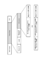
- FIG. 2 is a diagram showing a functional configuration of a communication apparatus 200 to which the technology disclosed in the present specification can be applied.
- FIG. 3 is a diagram illustrating an example of a communication sequence according to the first embodiment.
- FIG. 4 is a diagram illustrating another exemplary sequence of communication according to the first embodiment.
- FIG. 5 is a flowchart showing a processing procedure performed by the APAP on a subordinate isolated STA.
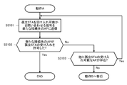
- FIG. 6 is a flow chart showing a processing procedure for determining whether or not an AP connects a subordinate isolated STA to another AP.
- FIG. 1 is a diagram showing a configuration example of a wireless communication system to which the technology disclosed in the present specification can be applied.
- FIG. 2 is a diagram showing a functional configuration of a communication apparatus 200 to which the technology disclosed in the present specification can be applied.
- FIG. 3 is a
- FIG. 7 is a flowchart showing the procedure of an operation A performed when an AP connects a subordinate isolated STA to another AP.
- FIG. 8 is a flowchart showing the procedure of an operation B performed when an AP does not connect a subordinate isolated STA to another AP.
- FIG. 9 is a diagram showing a frame configuration of a signal that an AP transmits to the subordinate isolated STA when requesting connection to another AP.
- FIG. 10 is a flowchart showing a processing procedure performed when an isolated STA receives a signal requesting connection to another AP.
- FIG. 11 is a diagram showing a frame configuration of a signal that an isolated STA transmits to a new connection destination AP.
- FIG. 12 is a diagram showing a frame configuration of a signal notifying that an AP can accept an isolated STA to neighboring APs.
- FIG. 13 is a diagram illustrating a modification of the communication sequence according to the first embodiment.
- FIG. 14 is a diagram illustrating another modification of the communication sequence according to the first embodiment.
- FIG. 15 is a flowchart showing a processing procedure of an operation A performed when an AP connects a subordinate isolated STA to another AP.
- FIG. 16 is a flowchart showing the procedure of an operation B performed when an AP does not connect a subordinate isolated STA to another AP.
- FIG. 17 is a diagram showing a frame configuration of a signal that an AP transmits to the subordinate isolated STA at the time of requesting connection to another AP.
- FIG. 18 is a flowchart showing a processing procedure performed when an isolated STA receives a signal requesting connection to another AP.
- FIG. 19 is a diagram showing a frame configuration of a signal that an isolated STA transmits to a new connection destination AP.
- FIG. 20 is a diagram showing an operation example in a wireless communication system to which the first embodiment is applied.
- FIG. 21 is a diagram illustrating an example of a communication sequence according to the second embodiment.
- FIG. 22 is a diagram illustrating another communication sequence example according to the second embodiment.
- FIG. 23 is a flowchart showing the procedure of an operation A performed when an AP connects a subordinate isolated STA to another AP in the second embodiment.
- FIG. 24 is a flowchart showing the procedure of an operation B performed when the AP does not change the connection destination of the subordinate isolated STA in the second embodiment.
- FIG. 25 is a diagram showing a frame configuration of a signal inquiring whether an AP can accept an isolated STA from other APs.
- FIG. 26 is a flowchart showing a processing procedure of a signal inquiring whether or not an isolated STA can be accepted.
- FIG. 27 is a diagram showing a frame configuration of an answer signal to an isolated STA acceptance query.
- FIG. 28 is a diagram showing a frame configuration of a signal for requesting a connection from a subordinate isolated STA to a new connection destination AP.
- FIG. 29 is a diagram illustrating a modification of the communication sequence according to the second embodiment.
- FIG. 29 is a diagram illustrating a modification of the communication sequence according to the second embodiment.
- FIG. 30 is a diagram illustrating another modification of the communication sequence according to the second embodiment.
- FIG. 31 is a flowchart showing the procedure of an operation A performed when an AP connects a subordinate isolated STA to another AP.
- FIG. 32 is a flowchart showing the procedure of an operation B performed when an AP does not connect a subordinate isolated STA to another AP.
- FIG. 33 is a diagram showing a frame configuration of a signal inquiring whether an AP can accept an isolated STA from other APs.
- FIG. 34 is a flow chart showing a processing procedure of a signal inquiring whether or not the isolated STA can be accepted.
- the problems in UL MU communication will be described.
- the received power of the signal transmitted from each STA must be the same power to some extent. Therefore, if there are a small number of STAs with small received power (hereinafter, also referred to as "weak link STAs") due to propagation loss etc., selecting the weak link STA as a STA performing UL MU communication, STAs performing other UL MU communications should transmit with low transmission power in accordance with weak link STAs. As a result, the signal to noise power ratio is reduced, and the probability that the AP can not receive the packet correctly increases.
- the weak link STA is not selected as the STA performing MU communication, it is necessary to separately secure an opportunity for the weak link STA to perform single user (SU) communication in order to secure the throughput of the weak link STA. Since the weak link STA has poor communication quality, communication is performed using MCS (coding and modulation scheme) with a low data rate. For this reason, since a long time frequency resource is occupied for SU communication of the weak link STA, time for performing MU communication is relatively reduced. Even when there are STAs that hardly or can not perform UL MU communication due to set parameters or implementation reasons, it is necessary to ensure an opportunity to perform SU communication as well, so the time to perform MU communication It will decrease relatively.
- MCS coding and modulation scheme
- the SR communication when the weak link STA is present, if the signal detection threshold of the wireless LAN packet is increased, the packet transmitted by the weak link STA can not be detected, which greatly restricts the SR communication. As a result, the effect of the increase in the communication opportunity by SR communication can not be obtained.
- an unfair communication opportunity occurs when the STA performing SR communication and the STA performing little or no SR communication exist in the same BSS. For example, when an interference signal larger than the signal detection threshold arrives for two STAs performing SR communication and STAs performing SR communication from other BSSs hardly, SR communication is hardly performed or performed. Although STAs that can not do so are in the BUSY state, STAs that perform SR communication may be able to communicate by raising the signal detection threshold. As a result, only STAs capable of SR communication perform communication, and communication opportunities become increasingly unfair.
- the STA can not know whether it is a restriction on SR communication or MU communication operation in the BSS. Therefore, when viewed from the entire BSS, even if the STA can improve the throughput of the BSS and the throughput of the BSS by connecting to another connectable BSS, the STA itself can not judge that.
- a proposal has been made for a wireless communication method in which an AP can start association in a wireless transmission / reception unit see, for example, Patent Document 1.
- the AP transmits a signal requesting connection to another AP connected in backhaul to the subordinate STA based on its own traffic load.
- the STA associates with the corresponding other AP.
- association requests to STAs are transmitted using traffic load as a criterion. In other words, it does not determine how to associate STAs on the basis of the efficiency of SR transmission and UL MU communication.
- this wireless communication method is premised on connection between APs using a backhaul. In the wireless LAN network, basically, it is not assumed that the APs are connected by backhaul. That is, this wireless communication method can be applied only in a very limited wireless environment such as Enterprise WLAN.
- a mobile communication base station determines whether to handoff to another BS based on the received power of a mobile communication terminal (MT).
- BSs are connected by backhaul and managed by a common central control station.
- each AP operates in an autonomous distributed manner, and simply controlling the connection destination of the STA by using the received power as a judgment standard increases the traffic load of a certain AP. There is a risk of getting into a situation of being covered, and it becomes a problem as an operation.
- the AP optimizes the connection destination of the STA based on the distribution of the implementation status of the SR communication and UL MU communication of the STA under the control of the AP.
- the AP investigates the distribution of the implementation status of SR communication and UL MU communication of each subordinate STA, and performs operation selection based on the result.
- isolated STAs small number of STAs that have deviated from the distribution of the entire subordinate STAs If it is found that it exists, the AP requests such an isolated STA to transmit a report of information on an AP to which the STA itself can connect.
- An isolated STA is often a weak link STA whose received power is smaller due to propagation loss and the like than other STAs in the same BSS.
- the AP makes the isolated STA connect to the other connectable AP. It sends a signal including a request for connection, and information prompting re-setting of parameters that make it easy to obtain a transmission opportunity when the isolated STA connects to the other accessible AP. Thereafter, the isolated STA transmits a signal including information prompting the newly connected AP to reset the parameters notified from the previously connected AP.
- the AP informs the surrounding cooperative APs that it can accept the isolated STA.
- the APs can effectively take over isolated STAs subordinate to each other.
- the setting parameter is set as the reward. (Eg, it is acceptable to set dominant Contention Window size, AIFS, signal detection value).
- the above-described operation between APs can improve the throughput of the entire network. Also, for an isolated STA, by connecting to another AP, it may be possible to improve its own throughput without being in a state of low communication quality or in a state in which UL MU communication or SR communication can not be performed. In addition, the above-described operation between APs can be realized between BSSs not connected by backhaul.
- FIG. 1 schematically shows a configuration example of a wireless communication system to which the technology disclosed in the present specification can be applied.
- the illustrated system includes a plurality of wireless devices STA 1 , STA 2 ,..., STA K-1 , STA K ,..., STA N-1 , STA N.
- STA 0 , STA 1 ,..., And STA K-1 are base stations (APs)
- STA K ,..., STA N-1 and STA N are handsets or terminals (STAs).
- the number of base stations is not limited to a specific number and a specific number of terminals.
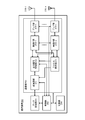
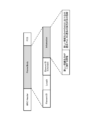
- FIG. 2 schematically shows a functional configuration of a communication apparatus 200 to which the technology disclosed in the present specification can be applied.
- the illustrated communication apparatus 200 can operate as either an AP or a STA, for example, in the wireless communication system shown in FIG.
- the communication device 200 includes a data processing unit 201, a control unit 202, a communication unit 203, and a power supply unit 204.
- the communication unit 203 further includes a modulation / demodulation unit 211, a signal processing unit 212, a channel estimation unit 213, a wireless interface (IF) unit 214, an amplifier unit 215, and an antenna 216.
- IF wireless interface
- the wireless interface unit 214, the amplifier unit 215, and the antenna 216 may be one set, and one or more sets may be components.
- the amplifier unit 215 may include the function in the wireless interface unit 214 in some cases.
- the antenna 216 may be externally connected to the main body of the communication device 200.
- the data processing unit 201 At the time of transmission in which data is input from a protocol upper layer (not shown), the data processing unit 201 generates a packet for wireless transmission from the data, and generates data for media access control (MAC). Processing such as addition of a header and addition of an error detection code is performed, and the processed data is provided to the modulation / demodulation unit 211 in the communication unit 203. Conversely, at the time of reception with input from the modem unit 211, the data processing unit 201 performs MAC header analysis, packet error detection and reordering processing, etc., and provides processed data to its own protocol upper layer Do.
- MAC media access control
- the control unit 202 controls exchange of information between the units in the communication device 200. Further, the control unit 202 performs parameter setting in the modulation unit 211 and the signal processing unit 212, and scheduling of packets in the data processing unit 201. Also, the control unit 202 performs parameter setting and transmission power control of the wireless interface unit 214 and the amplifier unit 215.
- the control unit 202 investigates the distribution of the implementation status of SR communication and UL MU communication of the wireless terminals under the control;
- the respective units are controlled so as to realize a process of specifying a wireless terminal (for example, an isolated STA in the BSS) whose connection should be changed to the base station.
- the control unit 202 prompts the isolated STA to reset parameters so as to easily obtain information for requesting connection to another AP and a communication opportunity to be transmitted when connecting to the corresponding base station.
- the control unit 202 transmits a signal (for example, a signal including information on communication parameters to be a reward) to the neighboring APs so that the STA subordinate to the other AP can easily be connected thereto. Control.
- the modulation / demodulation unit 211 performs encoding, interleaving and modulation on the input data from the data processing unit 201 based on the coding and modulation scheme set by the control unit 202, and generates a data symbol stream To the signal processing unit 212. Also, at the time of signal reception, the modem unit 211 performs processing opposite to that at the time of transmission on the input from the signal processing unit 212, and provides received data to the data processing unit 201 or the control unit 202.
- the signal processing unit 212 performs signal processing to be provided for spatial separation on the input from the modulation / demodulation unit 211 as necessary, and obtains one or more transmission symbol streams obtained from the respective wireless interfaces. To the section 214. Also, at the time of signal reception, the signal processing unit 212 performs signal processing on the received symbol stream input from each wireless interface unit 214, performs spatial resolution of the stream as necessary, and provides it to the modem unit 211. Do.
- the channel estimation unit 213 calculates complex channel gain information of the propagation path from the preamble portion and the training signal portion in the input signal from each of the radio interface units 214.
- the calculated complex channel gain information is used for demodulation processing in the modulation / demodulation unit 211 and spatial processing in the signal processing unit via the control unit 202.
- the wireless interface unit 214 converts an input from the signal processing unit into an analog signal, performs filtering, and up-converts to a carrier frequency, and transmits the signal to the antenna 216 or the amplifier unit 215. Also, at the time of signal reception, the wireless interface unit 214 performs the opposite process on the input from the antenna 216 or the amplifier unit 215, and provides data to the signal processing unit 212 and the channel estimation unit 213.
- the amplifier unit 215 At the time of signal transmission, the amplifier unit 215 amplifies the analog signal input from the wireless interface unit 214 to a predetermined power, and transmits the amplified signal to the antenna 216. Also, at the time of signal reception, the amplifier unit 215 performs low noise amplification of the signal input from the antenna 216 to a predetermined power, and outputs the amplified signal to the wireless interface unit 214. In the amplifier unit 215, at least one of the function at the time of transmission and the function at the time of reception may be included in the wireless interface unit 214.
- the power supply unit 204 is configured by a battery power supply or a fixed power supply, and supplies power to each unit in the communication device 200.
- the AP optimizes the connection destination of the STA based on the distribution of the implementation status of the SR communication and UL MU communication of the STA under the AP.
- two examples of the technology disclosed herein are introduced.
- the AP investigates the implementation status of SR communication and UL MU communication of each subordinate STA. If, as a result of investigation, it is found that there are a small number of isolated STAs that deviate from the distribution of the entire subordinate STAs, the AP selects one of the following two operations (a) or (b): And run.
- the AP requests the isolated STA to request connection to another designated AP, and at the same time, re-establishes parameters so as to easily obtain a communication opportunity to be transmitted when the isolated STA connects to the designated AP. Send a request signal including information prompting to set.
- B When an AP can accommodate an isolated STA connected to a neighboring AP, it notifies the neighboring AP that it can accept the isolated STA.
- the isolated STA makes a connection from the connecting AP to another designated AP. Then, when the isolated STA connects to the designated AP, it sends a signal including information prompting the newly connected AP to reset parameters sent from the previously connected AP. Do.
- the AP newly connected by the isolated STA changes its transmission parameter in accordance with the parameter information included in the signal received from the isolated STA.
- the AP when there is an isolated STA that matches the condition, the AP selects and executes one of the following two operations (c) or (d).
- the AP transmits a query signal to the AP to which the orphan STA under the connection can connect, inquiring whether or not the orphan STA may be connected. Then, when permission is obtained from the connectable AP, the AP requests the isolated STA to connect to the connectable AP and information when connecting to the connectable AP. A request signal is sent that includes information prompting you to reset the parameters to facilitate obtaining a communication opportunity to send. When the isolated STA connects to the connectable AP, it sends a signal including information prompting the new connected AP to reset parameters sent from the previously connected AP.
- D When an AP can accommodate an isolated STA connected to a neighboring AP, it notifies the neighboring AP that it can accept the isolated STA.
- an AP When an AP receives a signal confirming that it may connect a STA from another AP, it returns a signal indicating whether or not connection is possible.
- the isolated STA makes a connection to another AP specified by the request signal received from the connected AP.
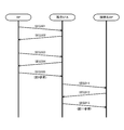
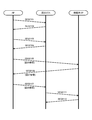
- FIG. 3 illustrates an example of a communication sequence performed between the AP, the isolated STA under the AP, and a new connection destination AP of the isolated STA in the first embodiment.
- the illustrated communication sequence assumes that an isolated STA can be connected to another AP (a connected AP in FIG. 3).
- the AP requests the STAs under its control to transmit information on communication quality and information on the implementation status to SR communication and UL MU communication (SEQ 301). In response to this, the STA returns the requested information to the AP (SEQ 302). Although omitted in FIG. 3, the AP requests the other STAs under its control to transmit similar information, and each STA returns the requested information to the AP. Then, as a result of investigating the implementation status of SR communication and UL MU communication of each STA under the AP, it is found that there exist isolated STAs which are out of the distribution of the entire STA under the AP.
- the AP requests the orphan STA to transmit information on other accessible APs (SEQ 303).
- the isolated STA sends back information on other accessible APs to the AP (SEQ 304).
- the information on the connectable APs returned by the isolated STA includes the size of the received power, the signal-to-noise power ratio, the SR communication or the UL as well as the identification information such as the SSID (Service Set Identifier) of the connectable APs.
- the state of implementation of MU communication may be included.
- the AP determines whether to change the isolated STA to a connection to another AP based on the information returned from the isolated STA.
- the AP requests a connection to the designated other AP from the subordinate orphan STA, and transmits a request signal including parameter information set for the other AP (SEQ 305).
- This parameter information is set as a reward for the other AP to accept the isolated STA.
- the AP determines, for example, the value of parameter information that makes it easier for the other AP to obtain a communication opportunity, according to the degree to which the AP wishes to assume the subordinate isolated STA.
- the isolated STA requests a connection to the new access point AP specified by the request signal (SEQ 311).
- the other APs that have received the connection request from the isolated STA determine whether to accept the isolated STA or not based on the information on the traffic load of the other AP. Then, when the isolated STA receives a response indicating that it can connect from the AP (SEQ 312), the isolated STA includes parameter information sent from the AP previously connected to the AP as the new connection destination. Send a signal (SEQ 313).
- the AP newly connected by the isolated STA changes its transmission parameter according to the parameter information included in the signal received from the isolated STA.
- the parameter information received from the isolated STA is set as a reward for accepting the isolated STA. It is expected that the new access point AP can be set to this parameter information in return for accepting the isolated STA, and it will be easier to obtain a communication opportunity.
- FIG. 4 illustrates another communication sequence example implemented between the AP, the isolated STA under the AP, and the connection destination AP in the first embodiment.
- the illustrated communication sequence assumes that an isolated STA can not connect to another AP (a connected AP in FIG. 4) and can accept the isolated STA of another AP.
- the AP requests the STAs under its control to transmit information on communication quality and information on implementation status to SR communication and UL MU communication (SEQ 401). In response to this, the STA returns the requested information to the AP (SEQ 402). Although omitted in FIG. 4, it is assumed that the AP requests transmission of similar information to other subordinate STAs, and each STA returns the requested information to the AP. Then, as a result of investigating the implementation status of SR communication and UL MU communication of each STA under the AP, it is found that there exist isolated STAs which are out of the distribution of the entire STA under the AP.
- the AP requests the orphan STA to transmit information on other accessible APs (SEQ 403).
- the isolated STA sends back information on other accessible APs to the AP (SEQ 404).
- Information on connectable APs returned by the isolated STA includes the size of received power, signal-to-noise power ratio, implementation status of SR communication or UL MU communication, etc., as well as identification information such as the SSID of connectable AP. You may be the same.
- the AP determines whether to change the isolated STA to a connection to another AP.
- the AP determines that the subordinate orphan STA can not connect to another AP, it gives up the handover of the orphan STA to the other AP.
- the AP notifies neighboring APs that it can accept the isolated STA (SEQ 411). Even if the AP can not cause the neighboring APs to assume the subordinate orphaned STAs, setting parameters (eg, Contention Window size, etc.) as rewards from the neighboring APs by assuming the orphaned STAs of other BSSs. It is expected to receive AIFS, signal detection value, etc.)
- the AP periodically collects information on the implementation status of SR communication and UL MU communication from each subordinate STA.
- Information on the implementation status of SR communication and UL MU communication includes the number of times SR transmission and MU communication were performed within a fixed period, the success probability of SR transmission and MU communication, the capability of SR transmission and MU communication, SR transmission and MU communication Information indicating whether the function is activated, current transmission power, signal-to-interference plus noise power ratio (SINR), or received signal strength indicator (RSSI) information is a combination of one or more.
- SINR signal-to-interference plus noise power ratio
- RSSI received signal strength indicator
- the AP may collect such information via a signal for communication quality report from the subordinate STA, or the AP itself may measure using a signal transmitted from the subordinate STA.
- the AP holds these pieces of information as parameter information of each subordinate STA.
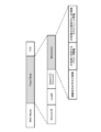
- An example of parameters held by the AP is shown in Table 1 below.
- the AP determines whether or not there is an isolated STA in the subordinate STAs based on the above-mentioned retention parameters.
- isolated STA refers to an STA whose parameter value is different when parameter information regarding the implementation status of SR communication or UL MU communication is compared for each STA.
- the AP looks at the distribution of the parameter values of the SR communication or UL MU communication implementation status, and determines a combination of multiple pieces of parameter information necessary to determine its operation.
- the AP refers to the distribution of parameter information regarding the implementation status of SR communication and UL MU communication that it holds, and determines an STA having parameter information that is out of the distribution as an isolated STA.
- the AP may refer to one or more types of stored parameter information.
- it is simply determined whether to hand over using communication quality as a criterion.
- the STA whose connection destination is to be changed is selected from the viewpoint of how to obtain the effect by performing SR communication and UL MU communication in the entire network.
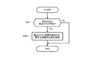
- FIG. 5 illustrates, in the form of a flowchart, a processing procedure performed by an AP on a subordinate isolated STA.
- the AP determines whether there is an isolated STA in the subordinate STAs (step S501). This determination may be performed at regular intervals using a timer held by the AP, or may be performed when the AP starts MU or SR communication. As described above, the parameter information regarding the implementation status of the SR communication or the UL MU communication is compared for each STA, and the STA whose parameter value is separated is determined as the isolated STA.
- the AP determines that there is an isolated STA in the subordinate STAs (Yes in step S501), it transmits a signal requesting transmission of information related to a connectable AP to the isolated STA. (Step S502).
- the destination of the request signal for requesting transmission of information on connectable APs may be addressed to individual isolated STAs, or may be signals addressed to a plurality of isolated STAs.
- the isolated STA in response to a request from an AP, includes identification information such as the SSID of the connectable AP, the magnitude of received power, signal-to-noise power ratio, SR communication Or it may include the implementation status of UL MU communication (same as above).
- the AP determines whether to connect the isolated STA to another AP.
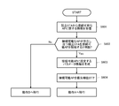
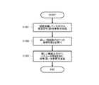
- FIG. 6 shows, in the form of a flowchart, a processing procedure for the AP to determine whether or not to connect a subordinate isolated STA to another AP.
- step S601 When an AP receives information on another AP that can be connected from the subordinate orphan STA (step S601), is there an AP to which the orphan STA can connect, and should the orphan STA be connected to the connectable AP? It is determined whether or not (step S602).
- step S602 when there is another AP to which the subordinate isolated STA can connect, there is information on the connectable AP received from the isolated STA and an AP to which the other isolated STA can connect. Information on the status of the SR communication or UL MU communication in the connectable AP, and any one or a combination of the number of isolated STAs for all subordinate STAs, and other STAs can be connected. It is determined whether to connect to the AP.
- step S603 When the AP determines that the subordinate isolated STA is to be connected to another connectable AP (Yes in step S602), parameter information to be set as a reward for having the connectable AP accept the connection of the isolated STA Are generated (step S603).
- the parameter information to be set as a reward for the applicable connectable AP is, for example, one of CW (Contention Windows) size, AIFS (Arbitration Inter Frame Space), TXOP (Transmission Opportunity), and signal detection threshold, or one of them. It is a combination of The AP may determine the value of parameter information that makes it easier for other APs to obtain a communication opportunity, depending on the degree to which another AP wishes to assume the subordinate isolated STA. For example, in the case where it is expected that the communication quality of an isolated STA in the own BSS is extremely low, and SR communication and UL MU communication in the own BSS can be more efficiently implemented by leaving the isolated STA, the isolated STA The more advanced parameter information may be set for an AP that wants to be accepted.
- the AP prioritizes the plurality of connectable APs, and holds the priorities of the connectable APs of the isolated STA (see FIG. Step S604).
- All APs have a list of APs (hereinafter, also referred to as “accepting APs”) that have notified neighboring APs that they can accept STAs.
- accepted APs The specific definition of acceptance AP will be given later.
- the AP refers to its accepting AP list, and confirms whether the accepting AP exists in an AP to which the subordinate orphan STA can connect.
- the priority of the accepting AP is set high.
- the priorities of the receiving APs and the APs that are not the receiving APs are determined based on the result of comparing the information of the implementation status of each SR communication and UL MU communication.
- step S604 when the prioritization in step S604 is completed, the AP shifts to operation A.
- the AP performs the operation B. Transition to
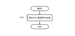
- FIG. 7 illustrates the processing procedure of the “operation A” described above, which is performed when an AP connects a subordinate isolated STA to another AP, in the form of a flowchart.
- the AP requests a connection to another connectable AP to the subordinate isolated STA, and transmits a request signal including information on parameter setting for the other AP (step S701). For example, the AP transmits a request signal including parameter information set as a reward for the other AP to take over its own isolated STA.
- step S701 in the flowchart shown in FIG. 7 and in SEQ 305 in the communication sequence shown in FIG. Shows a frame configuration of
- the AP may transmit this request signal only to the AP with the highest priority, or notifies all the accessible APs to the isolated STA.
- a request signal requesting connection may be transmitted in the order of priority.
- the frame shown in FIG. 9 includes a MAC header and a frame body (Frame Body), and a frame check sequence (FCS) is added at the end.
- the frame body includes an Element ID indicating the type of the information element, a Length indicating the length (data size) of the frame body, an Element ID Extension which is an extension of the information element, and an information portion (Information). Then, in the information part (Information) of the frame body, information indicating another AP requesting connection to the subordinate isolated STA (that is, information indicating the connection destination AP), and the information on the connection destination AP
- the set parameter information that is, parameter information for the connected AP is stored.
- the information indicating the connection destination AP may include one or both of the SSID and BSS color of the connection destination AP (SSID is an identification name of the AP in the wireless LAN.
- BSS Color is the IEEE 802. It is a different color information that is introduced for each BSS introduced in 11 ah).
- the parameter information for the connection destination AP is parameter information generated for an isolated STA for which it is determined that the AP changes the connection to another AP in step S603 of the flowchart shown in FIG.
- the AP generates parameter information set as a reward for the other APs to assume its own isolated STA. For example, the AP determines the value of parameter information that makes it easier for the other AP to obtain a communication opportunity, according to the degree to which the AP wishes to have the other isolated STA take over.
- FIG. 10 illustrates, in the form of a flowchart, a processing procedure performed when an isolated STA receives a request signal for requesting connection to another AP.
- step S1001 When the isolated STA receives a request signal (see FIG. 9) for requesting connection to another connectable AP from the currently connected AP (step S1001), a new connection destination is received from the received request signal. The connection procedure to the other AP shown as is performed (step S1002).
- the isolated STA transmits a signal including parameter information described in the request signal received in step S1001 to the AP of the new connection destination. (Step S1003).
- FIG. 11 shows a frame configuration of a signal that an isolated STA transmits to a new connection destination AP in step S1003 in the flowchart shown in FIG. 10 and SEQ 313 in the communication sequence shown in FIG. .
- the illustrated frame includes a MAC header and a frame body (Frame Body), and a frame check sequence (FCS) is added at the end.
- the frame body includes an Element ID indicating the type of the information element, a Length indicating the length (data size) of the frame body, an Element ID Extension which is an extension of the information element, and an information portion (Information). Then, the information part (Information) of the frame body contains information of parameter setting for the (new connection destination) AP.
- This parameter information is parameter information generated when it is determined in step S603 in the flowchart shown in FIG. 6 that the AP of the original connection destination changes the connection to another AP.
- the original AP to which the AP is connected generates parameter information set as a reward for the other APs to assume the lone STA.
- the AP of the original connection destination determines the value of parameter information that makes it easier for the other AP to obtain a communication opportunity according to the degree to which another AP wishes to take over the subordinate isolated STA (described above) .
- the newly connected AP may update its parameters based on the parameter information described in the signal received from the newly connected STA.
- FIG. 8 shows the processing procedure of the above-mentioned “operation B” in the form of a flowchart, which is executed by the AP when there is no other AP that can connect the subordinate isolated STA or does not connect to the other AP. ing.
- the AP determines whether it can currently accept an isolated STA of another BSS (step S801). Then, if it is possible to accept an isolated STA of another BSS (Yes in step S801), the AP broadcasts a signal indicating that it can accept an isolated STA to neighboring APs. On the other hand, when it is not possible to accept an isolated STA of another BSS (No in step S801), the AP ends this processing without doing anything.
- the illustrated frame includes a MAC header and a frame body (Frame Body), and a frame check sequence (FCS) is added at the end.
- the frame body includes an Element ID indicating the type of the information element, a Length indicating the length (data size) of the frame body, an Element ID Extension which is an extension of the information element, and an information portion (Information). Then, the information part (Information) of the frame body contains information on the AP itself which is the transmission source of the frame.
- the information on the AP itself may include SR information or the implementation status of UL MU communication, information on interference, traffic load of the AP, or a combination thereof. Based on the received information, the neighboring APs can determine whether the source AP can accept an isolated STA in its BSS.
- An AP that actively attempts to accept an isolated STA in another BSS is defined herein as an "accepting AP".
- accepting AP An AP that actively attempts to accept an isolated STA in another BSS.
- each AP receives a signal as shown in FIG. 12 from the neighboring APs, it adds the signal source AP to its accepting AP list.
- the acceptance AP list may describe information on APs described in the received signal.
- the AP performs operation B (see FIG. 8) when the AP does not request connection of the subordinate isolated STA to another AP, the AP rewards by accepting the isolated STA from the other BSS. It becomes possible to set parameters (CW size, AIFS, TXOP, signal detection threshold, etc.) which are advantageous as themselves. This can improve throughput and communication opportunities.
- each BSS operates in an autonomous distributed manner, and the operation of accepting STAs of other BSSs is only disadvantageous for the own BSS.
- this embodiment by introducing an action of setting a parameter as a reward for an AP that has accepted an isolated STA, cooperation between APs that are not connected by backhaul is realized. doing.
- FIG. 13 shows a modified example of the communication sequence performed between the AP, the isolated STA under the AP, and the new connection destination AP of the isolated STA in the first embodiment.
- the illustrated communication sequence assumes that an isolated STA can be connected to another AP (a connected AP in FIG. 3).
- the AP requests the subordinate STAs to transmit information on communication quality and information on the implementation status to SR communication and UL MU communication (SEQ 1301).
- the STA sends back the requested information to the AP (SEQ 1302).
- SEQ 1302 the STA sends back the requested information to the AP.
- the AP requests the orphan STA to transmit information on other connectable APs (SEQ 1303).
- the isolated STA sends back information on other accessible APs to the AP (SEQ1304).
- Information on connectable APs sent back by the isolated STA includes the size of received power, signal-to-noise power ratio, SR communication or UL MU communication, as well as identification information such as the SSID (Service Set Identifier) of the connectable AP. Implementation status may be included.
- the AP determines whether to change the isolated STA to a connection to another AP. Since the process of determining whether an AP connects a subordinate isolated STA to another AP is the same as that described above, detailed description will be omitted.
- the AP requests a connection to the designated other AP from the subordinate orphan STA, and transmits a signal including its own parameter information (SEQ 1305).
- An AP resets its parameter information so that the other AP becomes advantageous (or it becomes easy to obtain a communication opportunity), as a reward for having another orphaned STA under its charge. You may do so.
- the orphan STA requests a connection to the designated other AP (SEQ 1311). Then, when the isolated STA receives a response indicating that it can connect from the AP (SEQ 1312), the isolated STA includes parameter information sent from the AP previously connected to the AP as the new connection destination. The signal is transmitted (SEQ 1313).
- the parameter information received by the new connection destination AP is its own parameter information set as a reward in response to the original connection destination AP receiving the isolated STA. Therefore, it is expected that the AP of the new connection destination can more easily obtain the communication opportunity by resetting the parameter information within the range allowed by the received parameter information.
- FIG. 14 shows another modified example of the communication sequence performed between the AP, the isolated STA under the AP, and the connection destination AP in the first embodiment.
- the illustrated communication sequence assumes that an isolated STA can not connect to another AP (a connected AP in FIG. 14) and can accept the isolated STA of another AP.
- the AP requests the subordinate STAs to transmit information on communication quality and information on implementation status to SR communication and UL MU communication (SEQ 1401).
- the STA returns the requested information to the AP (SEQ 1402).
- SEQ 1402 the STA returns the requested information to the AP.
- the AP requests the orphan STA to transmit information on other accessible APs (SEQ 1403).
- the isolated STA sends back information on other connectable APs to the AP (SEQ 1404).
- the AP decides whether to change the isolated STA to a connection to another AP. Since the process of determining whether an AP connects a subordinate isolated STA to another AP is the same as that described above, detailed description will be omitted. Then, the AP determines whether to change the isolated STA to a connection to another AP.
- the AP determines that the subordinate orphan STA can not connect to another AP, it gives up the handover of the orphan STA to the other AP. Also, if the AP can accommodate an isolated STA connected to another AP, it notifies the neighboring APs that it can accept the isolated STA (SEQ 1411). Even if the AP can not cause the neighboring APs to assume the subordinate orphaned STAs, setting parameters (eg, Contention Window size, etc.) as rewards from the neighboring APs by assuming the orphaned STAs of other BSSs. It is expected to receive AIFS, signal detection value, etc.)
- the AP basically determines whether or not to connect the subordinate isolated STA to another AP according to the processing procedure shown in FIG. 5 and FIG.
- parameter information to be set in the AP itself is generated instead of parameter information to be set in the AP of the connection destination.
- the AP generates the parameter information of the AP itself (which suppresses the communication opportunity) so that the connected AP can re-set the parameter information that becomes advantageous as a reward for having the subordinate orphaned STA take over.
- the AP executes the operation A when determining that the subordinate isolated STA is to be connected to another AP, and executes the operation B when determining not to connect to another AP.
- FIG. 15 illustrates, in the form of a flowchart, a processing procedure of “operation A” performed when an AP connects a subordinate isolated STA to another AP according to the modification of the communication sequence illustrated in FIG.
- the AP sends a request signal including its own parameter information to be reset when the AP is changed to the other AP while requesting the connection to the other connectable AP from the subordinate isolated STA.
- This parameter information is composed of a value that makes the other AP advantageous (or makes it easy to obtain a communication opportunity) as a reward for the AP taking over for the subordinate STA.
- step S1502 the AP resets its parameter information to the value transmitted in step S1501 (step S1502). This is expected to make it easier for the other APs that have accepted the isolated STA to get a communication opportunity.
- FIG. 17 shows a frame configuration of a request signal that the AP transmits to the subordinate isolated STA in step S1501 in the flowchart shown in FIG. 15 and SEQ 1305 in the communication sequence shown in FIG.
- the illustrated frame includes a MAC header and a frame body (Frame Body), and a frame check sequence (FCS) is added at the end.
- the frame body includes an Element ID indicating the type of the information element, a Length indicating the length (data size) of the frame body, an Element ID Extension which is an extension of the information element, and an information portion (Information).
- information part (Information) of the frame body information indicating other APs requesting connection to the subordinate isolated STA, parameter information to be set for the transmission source AP itself, and transmission source information It includes schedule information of SR communication and UL MU communication in the own BSS of the AP.
- the information indicating the connection destination AP may include one or both of the SSID of the connection destination AP and the BSS color.
- parameter information to be set for the transmission source AP itself is any of CW size, AIFS, TXOP, and signal detection threshold value set in the AP itself after the subordinate isolated STA changes to connection to the connection destination AP. Or a combination of these.
- the parameter information to be set for the transmission source AP itself, and the schedule information of SR communication and UL MU communication in the own BSS of the transmission source AP are the processes corresponding to step S603 in the flowchart shown in FIG. It is own parameter information and schedule information set by the AP.
- an AP decides which other AP to connect its own orphan STA, it rewards itself for taking over the orphan STA so that the other AP becomes advantageous (or it becomes easy to get a communication opportunity), (Restricted the communication opportunities) and set up a schedule to perform SR communication and UL MU communication in the own BSS so that the other AP can easily obtain the communication opportunities.
- FIG. 18 illustrates, in the form of a flowchart, a processing procedure performed when the isolated STA receives a request signal for requesting a connection to another AP from a currently connected AP.
- the isolated STA When the isolated STA receives a signal requesting connection to another connectable AP from the connected AP (step S1801), it performs a connection procedure to the other AP (step S1802).
- the isolated STA is a signal requesting connection, including the parameter information and schedule information of the AP of the original connection destination described in the signal, It transmits with respect to the said other AP (step S1803).
- FIG. 19 shows a frame configuration of a signal that an isolated STA transmits to a new connection destination AP in step S1803 in the flowchart shown in FIG. 18 and SEQ 1313 in the communication sequence shown in FIG. .
- the illustrated frame includes a MAC header and a frame body (Frame Body), and a frame check sequence (FCS) is added at the end.
- the frame body includes an Element ID indicating the type of the information element, a Length indicating the length (data size) of the frame body, an Element ID Extension which is an extension of the information element, and an information portion (Information).
- the information part (Information) of the frame body contains the parameter information of the original connection destination AP, and the schedule information of the SR communication and UL MU communication of the original connection destination AP.
- the parameter information of the original connection destination AP is one of CW size, AIFS, TXOP, signal detection threshold, or a combination thereof.
- the parameter information and schedule information of the original connection destination AP are their own parameter information and schedule information set by the AP as processing corresponding to step S603 in the flowchart shown in FIG.
- the AP of the original connection destination may benefit (or may easily obtain a communication opportunity) the AP of the new connection destination (that is, the destination of the signal shown in FIG. 19) as a reward for accepting the isolated STA.
- the AP of the new connection destination has an advantage (or communication opportunity) within the range allowed by the parameter information and schedule information set for the AP itself of the original connection destination in return as the acceptance of the isolated STA. Resetting the parameter information of one's own (which suppressed the communication opportunity) to be easy to obtain), and setting the schedule of SR communication and UL MU communication in the own BSS so as to make it easy to obtain the communication opportunity it can.
- the AP performs “action when there is no other AP that can connect the lone STA under the AP or no connection to another AP”.
- the processing procedure of B is shown in the form of a flowchart.
- the processing procedure shown in FIG. 16 in the operation B is basically the same as the processing procedure shown in FIG.
- the AP determines whether it can currently accept an isolated STA of another BSS (step S1601). Then, if it is possible to accept an isolated STA of another BSS (Yes in step S1601), the AP broadcasts a signal indicating that it can accept an isolated STA (step S1602). ).
- the frame configuration of this signal is, for example, as shown in FIG.
- the AP ends this processing without doing anything.
- the AP when performing an action B (see FIG. 16) when the AP does not request connection of the subordinate isolated STA to another AP, the AP accepts the isolated STA from the other BSS. It becomes possible to set parameters (CW size, AIFS, TXOP, signal detection threshold, etc.) that will be advantageous as a reward. This can improve throughput and communication opportunities.
- each BSS operates in an autonomous distributed manner, and the operation of accepting STAs of other BSSs is only disadvantageous for the own BSS.
- this embodiment by introducing an action of setting a parameter as a reward for an AP that has accepted an isolated STA, cooperation between APs that are not connected by backhaul is realized. doing.
- FIG. 20 shows an operation example in a wireless communication system to which the present embodiment is applied.
- the illustrated wireless communication system includes a BSS operated by the base station AP1 and a BSS operated by the base station AP2.
- the terminals STA1 to STA6 are connected to the AP1, and the terminals STA7 to STA9 are connected to the AP2.
- STA3 is an isolated STA. Since STA3 can also connect to AP2, AP1 requests STA3 to connect to AP3. Also, AP1 resets own parameter information so that AP2 becomes advantageous (or can easily obtain a communication opportunity) as a reward for AP2 taking on STA3, and further, AP2 obtains a communication opportunity.
- the AP 1 can effectively perform SR communication and UL MU communication in its own BSS by having the neighboring APs 2 take over the isolated STA 3 under the subordinate. Become. As a result, in the own BSS, space reuse improves throughput.
- FIG. 21 illustrates an example of a communication sequence performed between an AP, an isolated STA under the AP, and a new connection destination AP of the isolated STA in the second embodiment.
- the illustrated communication sequence assumes that an isolated STA can be connected to another AP (a connected AP in FIG. 21).
- the AP requests the subordinate STAs to transmit information on communication quality and information on implementation status to SR communication and UL MU communication (SEQ2101).
- the STA sends back requested information to the AP (SEQ2102).
- SEQ2102 the STA sends back requested information to the AP.
- the AP requests the orphan STA to transmit information on other accessible APs (SEQ 2103).
- the isolated STA returns information on other connectable APs to the AP (SEQ 2104).
- Information on connectable APs returned by the isolated STA includes the size of received power, signal-to-noise power ratio, implementation status of SR communication or UL MU communication, etc., as well as identification information such as the SSID of connectable AP. You may be the same.
- the AP determines whether to change the isolated STA to a connection to another AP based on the information returned from the isolated STA. Then, the AP transmits, to the other AP determined to be the new connection destination of the isolated STA, a query signal inquiring whether the isolated STA can be accepted (SEQ 2105).
- This inquiry signal includes information on subordinate STAs and parameter information set for the other AP.
- the parameter information is set as a reward for the other AP to accept the isolated STA.
- the AP determines the value of parameter information that makes it easier to obtain a communication opportunity according to the degree to which it wants to take over the subordinate isolated STA.
- the other AP that has received the inquiry determines whether or not to accept the isolated STA, based on the information on the isolated STA included in the inquiry signal, parameter information, the information on the traffic load held by the other AP itself, and the like. Then, the other AP returns an answer signal indicating whether or not to accept the isolated STA (SEQ 2106).
- FIG. 21 shows an example of a communication sequence in the case of returning an answer signal indicating that another AP that has received the inquiry signal can accept the isolated STA.
- the AP When the AP confirms that the AP that has transmitted the inquiry signal can accept the isolated STA based on the received answer signal, the AP requests the subordinate isolated STA to connect to the AP of the new connection destination.
- a request signal including information on the implementation status of SR communication and UL MU communication in the BSS of the new connection destination AP is transmitted (SEQ 2107).
- the isolated STA requests a connection to the new access point AP specified by the request signal (SEQ 2111). Then, when the isolated STA receives a response indicating that it can connect from the AP (SEQ 2112), the connection to the AP of the new connection destination is completed. Since it is already a confirmation figure that the new access point AP can accept the isolated STA, it is expected that the connection change of the isolated STA will proceed smoothly.
- FIG. 22 illustrates another communication sequence example implemented between the AP, the isolated STA under the AP, and the connection destination AP in the second embodiment.
- the illustrated communication sequence assumes that an isolated STA can not connect to another AP (a connected AP in FIG. 22) and can accept an isolated STA of another AP.
- the AP requests the subordinate STAs to transmit information on communication quality and information on the implementation status to SR communication and UL MU communication (SEQ 2201).
- the STA returns the requested information to the AP (SEQ 2202).
- SEQ 2202 the SEQ 2202.
- the AP requests the orphan STA to transmit information on other connectable APs (SEQ2203).
- the isolated STA sends back information on other accessible APs to the AP (SEQ 2204).
- Information on connectable APs returned by the isolated STA includes the size of received power, signal-to-noise power ratio, implementation status of SR communication or UL MU communication, etc., as well as identification information such as the SSID of connectable AP. You may be the same.
- the AP determines whether to change the isolated STA to a connection to another AP.
- the AP determines that the subordinate orphan STA can not connect to another AP, it gives up the handover of the orphan STA to the other AP. Also, when an AP can accommodate an isolated STA connected to another AP, the AP notifies neighboring APs that it can accept the isolated STA (SEQ2211). Even if the AP can not cause the neighboring APs to assume the subordinate orphaned STAs, setting parameters (eg, Contention Window size, etc.) as rewards from the neighboring APs by assuming the orphaned STAs of other BSSs. It is expected to receive AIFS, signal detection value, etc.)
- the AP basically determines whether or not to connect the subordinate isolated STA to another AP according to the processing procedure shown in FIG. 5 and FIG. 6, so detailed description will be omitted here. Also in the second embodiment, the AP executes the operation A when determining to connect the subordinate isolated STA to another AP, and executes the operation B when determining not to connect to another AP.
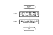
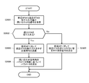
- FIG. 23 illustrates, in the form of a flowchart, a processing procedure of “operation A” performed when an AP connects a subordinate isolated STA to another AP in the second embodiment.
- the AP transmits a query signal to other APs determined to be new connection destinations of the isolated STA as to whether it is possible to accept the isolated STA (step S2301).
- step S2302 when connection of the isolated STA is permitted from the new connection destination AP of the isolated STA (Yes in step S2302), the AP requests the subordinate isolated STA to connect to the new connection destination AP.
- a signal including information on the implementation status of SR communication and UL MU communication in the BSS of the new connection destination AP is transmitted (step S2303).
- the AP transmits the above request signal to the isolated STA in the order of high priority.
- the AP checks whether there are more APs that can connect the isolated STA (step S2304). .
- step S2304 If there are more APs that can connect the isolated STA (Yes in step S2304), the process returns to step S2301, and repeatedly transmits the same inquiry signal to the other AP. Also, when there is no other AP that can accept the isolated STA (No in step S2304), the AP gives up changing the connection destination of the subordinate isolated STA, and executes the operation B.
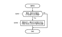
- FIG. 24 illustrates, in the form of a flowchart, a processing procedure of “operation B” performed when the AP does not change the connection destination of the subordinate STA in the second embodiment.
- the AP determines whether it can currently accept an isolated STA of another BSS (step S2401). Then, if it is possible to accept an isolated STA of another BSS (Yes in step S2401), the AP broadcasts a signal indicating that it is possible to accept the isolated STA (step S2402). ). On the other hand, when it is not possible to accept an isolated STA of another BSS (No in step S2401), the AP ends this processing without doing anything.
- the illustrated frame includes a MAC header and a frame body (Frame Body), and a frame check sequence (FCS) is added at the end.
- the frame body includes an Element ID indicating the type of the information element, a Length indicating the length (data size) of the frame body, an Element ID Extension which is an extension of the information element, and an information portion (Information). Then, the information part (Information) of the frame body includes information for inquiring whether or not the isolated STA can be accepted.
- the number of isolated STAs is a parameter representing the number of STAs determined to be isolated STAs under the AP of the inquiry source. Other APs that have received the signal can determine whether or not the inquiring AP can perform SR communication and UL MU communication by referring to this parameter.
- Status information on the isolated STA includes the AID (Associate ID) of the isolated STA, the Partial AID, the current RSSI or SINR of the isolated STA, the number of other accessible APs of the isolated STA, and the BSS to which the isolated STA belongs.
- AID Associate ID
- a single signal asking whether or not an isolated STA can be accepted may simultaneously inquire whether or not the plurality of isolated STAs can be accepted.
- status information on the isolated STAs is added by the number of the isolated STAs to be inquired.
- the parameter information for the inquiry destination AP is the parameter information generated for the isolated STA for which the AP has determined to change the connection to another AP in step S603 of the flowchart illustrated in FIG. CW size, AIFS, TXOP, signal detection threshold etc.).
- the AP generates parameter information set as a reward for the concerned AP to assume its own isolated STA. For example, the AP determines the value of parameter information that makes it easier for the inquired AP to obtain a communication opportunity according to the degree to which another AP wishes to assume the subordinate isolated STA. Also, when the AP of the inquiry destination accepts the isolated STA, it sets or updates its parameter based on the parameter information described here.
- FIG. 26 shows, in the form of a flowchart, a procedure for processing an inquiry signal, which is received from another AP and inquired as to whether or not it can accept an isolated STA.
- the AP determines whether or not to accept the isolated STA (step S2602).
- the AP has, for example, status information of the isolated STA such as the number of the isolated STAs described in the received inquiry signal, the implementation status of SR communication and UL MU communication, and the reason for being determined as the isolated STA. It is determined whether to accept the isolated STA or not based on the information of traffic load and the like.
- step S2602 When the AP accepts the inquired isolated STA (Yes in step S2602), the AP returns an answer signal indicating acceptance of the isolated STA to the inquirer AP (step S2603), and writes in the inquiry signal. Based on the received parameter information, its own parameter is set or updated (step S2604).
- step S2602 when the AP does not accept the inquired isolated STA (No in step S2602), the AP sends an answer signal indicating that the isolated STA is not accepted to the inquirer AP (step S2605). This process ends.
- the AP receives from the neighboring AP in step S2603 or S2605 in the flowchart shown in FIG. 26 and SEQ 2106 in the communication sequence shown in FIG. 3 shows the frame configuration of an answer signal to be answered in response to the query of.
- the illustrated frame includes a MAC header and a frame body (Frame Body), and a frame check sequence (FCS) is added at the end.
- the frame body includes an Element ID indicating the type of the information element, a Length indicating the length (data size) of the frame body, an Element ID Extension which is an extension of the information element, and an information portion (Information).
- the information part (Information) of the frame body includes information for indicating a response to the isolated STA acceptance query (that is, whether to accept the isolated STA) and information indicating the state of the BSS to which the AP belongs. .
- the information indicating whether to accept the isolated STA is a 1-bit flag indicating whether to accept or not.
- the information indicating the state of the BSS to which the AP belongs includes information on the implementation status of SR communication and UL MU communication in its own BSS, information on traffic load, the number of STAs determined to be isolated STAs, and the like.
- an AP accepts an isolated STA from neighboring APs, it adds information indicating the status of its own BSS in the response signal.
- the isolated STA changes its own parameters such as signal detection value, maximum transmission power, and communication mode based on the information indicating the state of the BSS added to the answer signal, when belonging to the AP's BSS that has accepted the acceptance. can do. By this, the isolated STA can be promptly put into a state suitable for performing communication with a new connection destination BSS.
- the inquiry source AP When the inquiry source AP receives an answer signal indicating that it does not accept an isolated STA from the inquired AP, it updates its acceptance AP list based on the information indicating the status of the BSS added in the signal. Or, the priority of the connectable APs of the isolated STAs can be updated. This enables the AP to change the connection destination of the isolated STA more efficiently.
- the request source AP requests the subordinate isolated STA to connect to a new connection destination AP.
- a signal including information on the implementation status of SR communication and UL MU communication in the BSS of the new connection destination AP is transmitted (a process corresponding to step S2303 in the flowchart shown in FIG. 23).
- the AP requests the isolated STA under its control to connect to the new connection destination AP.
- It shows the frame configuration of the signal.
- the illustrated frame includes a MAC header and a frame body (Frame Body), and a frame check sequence (FCS) is added at the end.
- the frame body includes an Element ID indicating the type of the information element, a Length indicating the length (data size) of the frame body, an Element ID Extension which is an extension of the information element, and an information portion (Information).
- the information part (Information) of the frame body includes information on the AP of the new connection destination and information on the implementation status of SR communication and UL MU communication in the BSS of the new connection destination AP.
- the information on the new connection destination AP may include one or both of the SSID and BSS color of the new connection destination AP. Further, information based on information indicating the state of the BSS to which the AP belongs, which is included in the reply signal, is described as information on the implementation status of SR communication and UL MU communication in the BSS of the new connection destination AP. By notifying the information on the implementation status of SR communication and UL MU communication in the BSS of the new connection destination AP, the isolated STA should be in an appropriate state to perform communication in the new connection BSS promptly. Can.
- the original APs of connection destinations transmit the above-mentioned request signals to the isolated STA in the descending order of priority.
- the AP shifts to operation B.
- the AP when performing an action B when an AP does not request a connection of a subordinate orphan STA to another AP, the AP can benefit itself as a reward by accepting the orphan STA from another BSS. It becomes possible to set parameters (CW size, AIFS, TXOP, signal detection threshold, etc.). This can improve throughput and communication opportunities.
- each BSS operates in an autonomous distributed manner, and the operation of accepting STAs of other BSSs is only disadvantageous for the own BSS.
- this embodiment by introducing an action of setting a parameter as a reward for an AP that has accepted an isolated STA, cooperation between APs that are not connected by backhaul is realized. doing.
- FIG. 29 shows a modified example of the communication sequence performed between the AP, the isolated STA under the AP, and the new connection destination AP of the isolated STA in the second embodiment.
- the illustrated communication sequence assumes that the isolated STA can be connected to another AP (a connected AP in FIG. 29).
- the AP requests the STAs under its control to transmit information on communication quality and information on the implementation status to SR communication and UL MU communication (SEQ 2901). On the other hand, the STA returns the requested information to the AP (SEQ 2902). Then, as a result of investigating the implementation status of SR communication and UL MU communication of each STA under the AP, it is found that there exist isolated STAs which are out of the distribution of the entire STA under the AP.
- the AP requests the orphan STA to transmit information on other accessible APs (SEQ 2903).
- the isolated STA returns information on other connectable APs to the AP (SEQ 2904).
- Information on connectable APs returned by the isolated STA includes the size of received power, signal-to-noise power ratio, implementation status of SR communication or UL MU communication, etc., as well as identification information such as the SSID of connectable AP. You may be the same.
- the AP determines whether to change the isolated STA to a connection to another AP based on the information returned from the isolated STA. Then, the AP transmits a signal inquiring to the other AP determined to be the new connection destination of the isolated STA as to whether or not the isolated STA can be accepted (SEQ 2905). If the other AP that has received the inquiry can accept the isolated STA, it returns an answer signal indicating that (SEQ 2906).
- the inquiry signal includes parameter information for the AP to be inquired and information on the isolated STA.
- the parameter information for the inquired AP is set as a reward for the inquiring AP to accept the isolated STA.
- the AP determines the value of parameter information that makes it easier for the inquired AP to obtain a communication opportunity according to, for example, the degree to which the AP wishes to assume a subordinate isolated STA.
- information on the isolated STA may be the AID of the isolated STA, the partial AID, the current RSSI or SINR of the isolated STA, the number of other accessible APs of the isolated STA, or SR communication of the BSS to which the isolated STA belongs. It consists of the implementation status of the MU communication operation, one of the reasons determined to be an isolated STA, or a combination of these.
- the inquiry signal includes parameter information set by the AP itself of the transmission source of the signal, schedule information for performing SR communication and UL MU communication in the BSS of the AP itself, and information on the isolated STA.
- the parameter information set by the transmission source AP itself and the schedule information for performing SR communication and UL MU communication in the BSS of the AP itself are set as a reward for receiving the isolated STA from the inquiry destination AP.
- the AP determines the value of parameter information and schedule information that make it easier for the inquired AP to obtain a communication opportunity according to the degree to which the AP wants to assume the subordinate isolated STA.
- the AP capable of accepting the isolated STA transmits a signal requesting the isolated STA to connect to itself as a new connection destination (SEQ 2911).
- FIG. 30 shows another modified example of the communication sequence performed between the AP, the isolated STA under the AP, and the connection destination AP in the second embodiment.
- the illustrated communication sequence assumes that an isolated STA can not connect to another AP (a connected AP in FIG. 30) and can accept the isolated STA of another AP.
- the AP requests the subordinate STAs to transmit information on communication quality and information on the implementation status to SR communication and UL MU communication (SEQ 3001).
- the STA returns the requested information to the AP (SEQ 3002).
- SEQ 3002 the STA returns the requested information to the AP.
- the AP requests the orphan STA to transmit information on other connectable APs (SEQ 3003).
- the isolated STA sends back information on other connectable APs to the AP (SEQ 3004).
- Information on connectable APs returned by the isolated STA includes the size of received power, signal-to-noise power ratio, implementation status of SR communication or UL MU communication, etc., as well as identification information such as the SSID of connectable AP. You may be the same.
- the AP determines whether to change the isolated STA to a connection to another AP.
- the AP determines that the subordinate orphan STA can not connect to another AP, it gives up the handover of the orphan STA to the other AP. Also, if the AP can accommodate an isolated STA connected to another AP, it notifies the neighboring APs that it can accept the isolated STA (SEQ 3011). Even if the AP can not cause the neighboring APs to assume the subordinate orphaned STAs, setting parameters (eg, Contention Window size, etc.) as rewards from the neighboring APs by assuming the orphaned STAs of other BSSs. It is expected to receive AIFS, signal detection value, etc.)
- the AP basically determines whether or not to connect the subordinate isolated STA to another AP according to the processing procedure shown in FIG. 5 and FIG. 6, so detailed description will be omitted here. Also in the modification of the second embodiment, the AP executes the operation A when determining that the subordinate isolated STA is to be connected to another AP, and executes the operation B when determining not to connect to another AP.
- FIG. 31 illustrates, in the form of a flowchart, a processing procedure of “operation A” performed when an AP connects a subordinate isolated STA to another AP in the modification of the second embodiment.
- the AP transmits a signal inquiring whether other APs determined to be new connection destinations of the isolated STA can accept the isolated STA (step S3101).
- the AP ends this processing. Thereafter, a connection is requested from the new connection destination AP to the isolated STA, and a new connection is to be implemented.
- the AP checks whether there is another AP that can connect the isolated STA (step S3103). .
- step S3103 If there are more APs that can connect the isolated STA (Yes in step S3103), the process returns to step S3101, and the same inquiry as above is repeatedly performed on the other AP. Also, when there is no other AP that can accept the isolated STA (No in step S3103), the AP gives up changing the connection destination of the subordinate isolated STA, and executes the operation B.
- the AP determines whether it can currently accept an isolated STA of another BSS (step S3201). Then, if it is possible to accept an isolated STA of another BSS (Yes in step S3201), the AP broadcasts a signal indicating that it can accept an isolated STA (step S3202). ). On the other hand, when it is not possible to accept an isolated STA of another BSS (No in step S3201), the AP ends this processing without doing anything.
- step S3201 in the flow chart shown in FIG. 32 and in SEQ 2905 in the communication sequence shown in FIG. It shows the configuration.
- the illustrated frame includes a MAC header and a frame body (Frame Body), and a frame check sequence (FCS) is added at the end.
- the frame body includes an Element ID indicating the type of the information element, a Length indicating the length (data size) of the frame body, an Element ID Extension which is an extension of the information element, and an information portion (Information).
- the information part (Information) of the frame body includes information for inquiring whether or not the isolated STA can be accepted.
- the parameter information for the inquired AP is the parameter information (CW size, AIFS, TXOP, etc.) set as a reward for the inquired AP in step S603 in the flowchart shown in FIG. 6 as in the first embodiment. Signal detection threshold etc.).
- the AP generates parameter information set as a reward for the concerned AP to assume its own isolated STA. For example, the AP determines the value of parameter information that makes it easier for the inquired AP to obtain a communication opportunity according to the degree to which another AP wishes to assume the subordinate isolated STA. Also, when the AP of the inquiry destination accepts the isolated STA, it sets or updates its parameter based on the parameter information described here.
- the parameter information for the inquiry destination AP in place of the parameter information for the inquiry destination AP, its own parameter information to be set in the transmission source AP, and schedule information of SR communication and UL MU communication in the own BSS of the transmission source AP are included in the same signal. It may be described.
- the parameter information set by the transmission source AP itself and the schedule information for performing SR communication and UL MU communication in the BSS of the AP itself are set as a reward for receiving the isolated STA from the inquiry destination AP.
- the AP determines the value of parameter information and schedule information that make it easier for the inquired AP to obtain a communication opportunity according to the degree to which the AP wants to assume the subordinate isolated STA.
- the AP of the inquiry destination accepts the isolated STA, it sets or updates its parameter based on the parameter information described here.
- Status information about the isolated STA includes AID, Partial AID, current RSSI or SINR of the corresponding isolated STA, the number of other accessible APs of the corresponding isolated STA, SR communication or MU communication of the BSS to which the corresponding isolated STA belongs It consists of the operation status of the operation, one of the reasons determined to be an isolated STA, or a combination of these.
- FIG. 34 illustrates, in the form of a flowchart, a procedure for processing a signal, which is received from another AP and inquired as to whether or not it is possible to accept an isolated STA.
- the AP determines whether to accept the isolated STA (step S3402).
- the AP is parameter information for the connection destination AP (or its own parameter information to be set at the transmission source AP, schedule information of SR communication or UL MU communication in the own BSS of the transmission source AP), isolation Based on status information on STAs, it is determined whether to accept an isolated STA.
- the AP When the AP accepts the inquired isolated STA (Yes in step S3402), the AP returns an answer signal indicating acceptance of the isolated STA to the inquirer AP (step S3403), and then the isolated STA. Transmits a signal requesting connection to itself (step S3404). Thereafter, the AP sets or updates its parameters based on the parameter information recorded in the signal inquiring the acceptance of the isolated STA.
- step S3402 when the AP does not accept the inquired isolated STA (No in step S3402), the AP returns an answer signal indicating that the isolated STA is not accepted to the inquiry source AP (step S3405). This process ends.
- step S3404 the isolated STA that has received the signal requesting connection from the new connection destination AP changes the connection to the new connection destination AP, for example, according to the same processing procedure as shown in FIG.
- the modified example shown in FIG. 29 and FIG. 30 has an effect that the isolated STA does not need to perform signaling regarding parameter setting.
- the AP of the new connection destination is transmitted immediately after the original connection destination AP transmits a Disassociation signal to the isolated STA.
- the connection change of the isolated STA can also be realized by transmitting the signal of the Association to the isolated STA.
- the technology disclosed herein can be suitably applied to a wireless network environment where multiple BSSs exist and APs are not connected by backhaul or the like.
- technologies such as SR communication and MU communication are used in each BSS
- the technology disclosed in this specification is applied to efficiently receive STAs with weak links and isolation among BSSs. By delivering, it is expected to realize high-speed communication.
- the technology disclosed herein can be applied to, for example, a wireless communication system according to IEEE 802.11ax, but of course can be applied to systems according to various other communication standards as well.
- a communication apparatus operating as a base station, A determination unit that determines the communication status in the BSS of the communication device; A control unit that controls transmission / reception of a signal related to connection change of a terminal with a nearby base station according to the determination result by the determination unit; A communication device comprising (2) The control unit controls transmission of a request signal for requesting a connection to the nearby base station to a subordinate terminal.
- the determination unit determines the presence of a small number of terminals in which the first parameter representing the communication quality indicator of the terminal deviates from the distribution of all terminals under the control;
- the control unit controls transmission of the request signal for requesting the connection to the neighboring base stations to the small number of terminals.
- the communication device according to (2) above. (3-1)
- the determination unit determines, as the first parameter, an implementation status of space reuse communication or multi-user communication of a subordinate terminal.
- (4) The control unit controls transmission of the request signal including a second parameter related to communication after the subordinate terminal changes connection to the neighboring base station.
- the communication apparatus according to any one of the above (2) or (3).
- the control unit as the second parameter, information on communication resources to be set in the own station after the subordinate terminal changes connection to the neighboring base station, or the neighboring base station Include in the request signal information on the communication resources allowed to The communication device according to (4) above.
- the information related to the communication resource as the second parameter includes the Contention Windows size, AIFS, signal detection threshold, or a combination thereof in the own station or the neighboring base station.
- the information on the communication resource to be set to the own station described in the request signal includes information on a schedule for implementing space reuse communication or multi-user communication in the BSS of the communication device.
- the communication device according to any one of the above (4-1) or (4-2).
- the control unit determines the second parameter based on the information of the first parameter, The communication apparatus according to any one of the above (4) to (4-3). (5) The control unit controls transmission of an inquiry signal inquiring whether or not the subordinate terminals accept the peripheral base stations. The communication device according to (1) above. (6) The determination unit determines the presence of a small number of terminals in which the first parameter representing the indicator of the communication quality of the terminal deviates from the distribution of all terminals under the control; The control unit controls transmission of the inquiry signal inquiring whether or not the small number of terminals accept the peripheral base stations. The communication device according to (5) above. (6-1) The determination unit determines, as the first parameter, an implementation status of space reuse communication or multi-user communication of a subordinate terminal.
- the communication device according to (6) above.
- the control unit performs the inquiry signal including information on the number of terminals subordinate to which connection is to be changed and the communication status of each terminal, or information on a specific terminal requesting acceptance of the surrounding base stations.
- Control transmission of the interrogation signal including The communication apparatus according to any one of the above (5) or (6).
- the control unit controls transmission of the inquiry signal including a second parameter related to communication after the subordinate terminal changes connection to the neighboring base station.
- the communication apparatus according to any one of the above (5) to (7).
- the control unit may use, as the second parameter, information on a communication resource to be set in the own station after the subordinate terminal changes connection to the neighboring base station, or the neighboring base station Including in the inquiry signal information regarding the communication resources allowed to The communication device according to (8) above.
- the information related to the communication resource as the second parameter is configured of a Contention Windows size, an AIFS, a signal detection threshold, or a combination thereof in the own station or the neighboring base station.
- the information on the communication resource set to the own station described in the inquiry signal includes information on an implementation schedule of space reuse communication or multi-user communication in the BSS of the communication device.
- the communication apparatus according to any one of the above (8-1) and (8-2).
- the control unit determines the second parameter based on the information of the first parameter, The communication device according to any one of the above (8) to (8-3).
- the control unit when receiving a response signal indicating acceptance of a subordinate terminal from the neighboring base stations, requests the subordinate terminals to connect to the neighboring base stations Control the transmission of the signal, The communication apparatus according to any one of the above (5) to (8).
- the control unit controls transmission of the request signal including information on the communication status in the BSS of the neighboring base stations added to the reply signal.
- the communication device according to (9).
- the control unit is configured to, based on a second parameter included in the signal received from either the terminal or the peripheral base station when connecting a terminal subordinate to a peripheral base station to the local station.
- the communication device Set up the communication parameters of your own station, The communication device according to (1) above. (11-1)
- the communication parameters of the own station are set based on the information on the communication resources that the surrounding base stations set for the station itself or the information on the communication resources that the neighboring base stations allow for the own station.
- the communication apparatus according to (11).
- the control unit may use Contention Windows size, AIFS, a signal detection threshold, or a combination thereof as the communication parameter of the own station, or space reuse communication in the BSS of the communication device, or Set the implementation schedule for multi-user communication, The communication apparatus according to any one of the above (11) or (11-1).
- the control unit upon receiving an inquiry signal inquiring as to whether or not the terminal subordinate to the peripheral base station accepts from the peripheral base stations, accepts the terminal subordinate to the peripheral base station Control the transmission of the answer signal to answer the The communication device according to (1) above.
- the control unit based on a second parameter related to communication after connection of the terminal added to the inquiry signal, or information on traffic load in the own station, subordinates of the surrounding base stations.
- the control unit determines if the terminal can accept or not The communication device according to (12).
- the control unit as the second parameter, information on communication resources permitted to the own station after connecting the terminal inquired for acceptance to the own station, or the base station in the periphery Based on the information on the communication resource set by the station itself, it is judged whether or not the terminal subordinate to the nearby base station can accept it.
- the communication device according to (13).
- (14) The communication apparatus according to (12) or (13), wherein the control unit controls transmission of the reply signal including information on the communication status in the BSS of the own station.
- the control unit attempts connection with the terminal.
- the communication apparatus according to any one of the above (12) or (13).
- a communication method for operating as a base station A determining step of determining a communication status in the BSS of the base station; A control step of controlling transmission and reception of a signal related to connection change of a terminal with a neighboring base station according to the determination result in the determination step;
- a communication method having: (17) A communication apparatus operating as a terminal under the control of a base station, A transmitting and receiving unit that transmits and receives signals; A control unit configured to control connection with a base station based on a request signal for requesting connection to another base station received from a connected base station; A communication device comprising (18) The control unit transmits, to the other base station after the connection is established, transmission of a second parameter related to communication after changing the connection to the other base station, which is included in the request signal.
- the communication device according to (17) above.
- the control unit as the second parameter, information on communication resources to be set in the base station itself after the base station of the original connection destination changes the connection to the other base station, or Control transmission of information on communication resources allowed to the other base station to the other base station after a connection is established,
- the communication apparatus according to (18).
- the information on the communication resource as the second parameter includes Contention Windows size, AIFS, signal detection threshold, or a combination thereof at the original connection destination or at the other base station.
- the communication device according to (18-1) above.
- the control unit changes the connection to the other base station, and then, based on the information related to the state of communication in the BSS of the other base station described in the request signal described in the request signal.
- the control unit may change the connection to the other base station, which is included in the request signal, to the other base station after the connection is established, of the base station of the original connection destination. Control transmission of information regarding implementation schedule of space reuse communication or multi-user communication in BSS.
- the communication apparatus according to any one of the above (17) or (18).
- communication device 201 data processing unit 202 control unit 203 communication unit 204 power supply unit 211 modulation / demodulation unit 212 spatial signal processing unit 213 channel estimation unit 214 wireless interface unit 215 amplifier unit , 216 ... antenna
Abstract
Description
前記通信装置のBSS内での通信状況を判定する判定部と、
前記判定部による判定結果に応じて、周辺の基地局との間で端末の接続変更に関する信号の送受信を制御する制御部と、
を具備する通信装置である。
前記基地局のBSS内での通信状況を判定する判定ステップと、
前記判定ステップにおける判定結果に応じて、周辺の基地局との間で端末の接続変更に関する信号の送受信を制御する制御ステップと、
を有する通信方法である。
信号を送受信する送受信部と、
接続先の基地局から受信した他の基地局への接続を要請する要請信号に基づいて、基地局との接続を制御する制御部と、
を具備する通信装置である。
接続先の基地局から受信した他の基地局への接続を要請する要請信号を受信する受信ステップと、
前記要請信号に基づいて、基地局との接続を制御する制御ステップと、
を有する通信方法である。
(b)APは、周辺のAPに接続している孤立STAを収容可能な場合には、周辺のAPに対して孤立STAを受け入れ可能であることを通知する。
(d)APは、周辺のAPに接続している孤立STAを収容可能な場合には、周辺のAPに対して孤立STAを受け入れ可能であることを通知する。

(1)基地局として動作する通信装置であって、
前記通信装置のBSS内での通信状況を判定する判定部と、
前記判定部による判定結果に応じて、周辺の基地局との間で端末の接続変更に関する信号の送受信を制御する制御部と、
を具備する通信装置。
(2)前記制御部は、配下の端末に対し、前記周辺の基地局への接続を要請する要請信号の送信を制御する、
上記(1)に記載の通信装置。
(3)前記判定部は、端末の通信品質の指標を表す第1のパラメータが配下の端末全体の分布から外れた少数の端末の存在を判定し、
前記制御部は、前記少数の端末に対し、前記周辺の基地局への接続を要請する前記要請信号の送信を制御する、
上記(2)に記載の通信装置。
(3-1)前記判定部は、前記第1のパラメータとして、配下の端末の空間再利用通信又はマルチユーザ通信の実施状況を判定する、
上記(3)に記載の通信装置。
(4)前記制御部は、前記配下の端末が前記周辺の基地局へ接続を変更した後の通信に関する第2のパラメータを含む前記要請信号の送信を制御する、
上記(2)又は(3)のいずれかに記載の通信装置。
(4-1)前記制御部は、前記第2のパラメータとして、前記配下の端末が前記周辺の基地局へ接続を変更した後に自局に設定する通信リソースに関する情報、又は、前記周辺の基地局に許容する通信リソースに関する情報を前記要請信号に含める、
上記(4)に記載の通信装置。
(4-2)前記第2のパラメータとしての通信リソースに関する情報は、自局又は前記周辺の基地局における、Contention Windowsサイズ、AIFS、信号検出閾値のいずれか又はこれらの組み合わせからなる、
上記(4-1)に記載の通信装置。
(4-3)前記要請信号に記載される前記の自局に設定する通信リソースに関する情報は、前記通信装置のBSS内での空間再利用通信又はマルチユーザ通信の実施予定に関する情報を含む、
上記(4-1)又は(4-2)のいずれかに記載の通信装置。
(4-4)前記制御部は、前記第1のパラメータの情報に基づいて前記第2のパラメータを決定する、
上記(4)乃至(4-3)のいずれかに記載の通信装置。
(5)前記制御部は、前記周辺の基地局に対し、配下の端末の受け入れの可否を問い合わせる問い合わせ信号の送信を制御する、
上記(1)に記載の通信装置。
(6)前記判定部は、端末の通信品質の指標を表す第1のパラメータが配下の端末全体の分布から外れた少数の端末の存在を判定し、
前記制御部は、前記周辺の基地局に対し、前記少数の端末の受け入れの可否を問い合わせる前記問い合わせ信号の送信を制御する、
上記(5)に記載の通信装置。
(6-1)前記判定部は、前記第1のパラメータとして、配下の端末の空間再利用通信又はマルチユーザ通信の実施状況を判定する、
上記(6)に記載の通信装置。
(7)前記制御部は、接続を変更したい配下の端末の数と各端末の通信状況に関する情報を含む前記問い合わせ信号、又は、前記周辺の基地局に対して受け入れを要請する特定の端末に関する情報を含む前記問い合わせ信号の送信を制御する、
上記(5)又は(6)のいずれかに記載の通信装置。
(8)前記制御部は、前記配下の端末が前記周辺の基地局へ接続を変更した後の通信に関する第2のパラメータを含む前記問い合わせ信号の送信を制御する、
上記(5)乃至(7)のいずれかに記載の通信装置。
(8-1)前記制御部は、前記第2のパラメータとして、前記配下の端末が前記周辺の基地局へ接続を変更した後に自局に設定する通信リソースに関する情報、又は、前記周辺の基地局に許容する通信リソースに関する情報を前記問い合わせ信号に含める、
上記(8)に記載の通信装置。
(8-2)前記第2のパラメータとしての前記通信リソースに関する情報は、自局又は前記周辺の基地局における、Contention Windowsサイズ、AIFS、信号検出閾値のいずれか又はこれらの組み合わせからなる、
上記(8-1)に記載の通信装置。
(8-3)前記問い合わせ信号に記載される前記の自局に設定する通信リソースに関する情報は、前記通信装置のBSS内での空間再利用通信又はマルチユーザ通信の実施予定に関する情報を含む、
上記(8-1)又は(8-2)のいずれかに記載の通信装置。
(8-4)前記制御部は、前記第1のパラメータの情報に基づいて前記第2のパラメータを決定する、
上記(8)乃至(8-3)のいずれかに記載の通信装置。
(9)前記制御部は、前記周辺の基地局から、配下の端末を受け入れることを示す回答信号を受信したときに、前記配下の端末に対し、前記周辺の基地局への接続を要請する要請信号の送信を制御する、
上記(5)乃至(8)のいずれかに記載の通信装置。
(10)前記制御部は、前記回答信号に付加されている、前記周辺の基地局のBSS内の通信状況に関する情報を含む前記要請信号の送信を制御する、
上記(9)に記載の通信装置。
(11)前記制御部は、周辺の基地局の配下の端末を自局に接続したときに、前記端末又は前記周辺の基地局のいずれかから受信した前記信号に含まれる第2のパラメータに基づいて、自局の通信パラメータを設定する、
上記(1)に記載の通信装置。
(11-1)前記制御部は、前記第2のパラメータとして含まれる、周辺の基地局の配下の端末を自局に接続したときに、前記端末又は前記周辺の基地局のいずれかから受信した前記周辺の基地局が当該局自身に設定する通信リソースに関する情報又は前記周辺の基地局が自局に許容する通信リソースに関する情報に基づいて、自局の通信パラメータを設定する、
上記(11)に記載の通信装置。
(11-2)前記制御部は、自局の前記通信パラメータとして、Contention Windowsサイズ、AIFS、信号検出閾値のいずれか又はこれらの組み合わせ、若しくは、前記通信装置のBSS内での空間再利用通信又はマルチユーザ通信の実施スケジュールを設定する、
上記(11)又は(11-1)のいずれかに記載の通信装置。
(12)前記制御部は、周辺の基地局から、前記周辺の基地局の配下の端末の受け入れの可否を問い合わせる問い合わせ信号を受信したことに応じて、前記周辺の基地局の配下の端末の受け入れの可否を回答する回答信号の送信を制御する、
上記(1)に記載の通信装置。
(13)前記制御部は、前記問い合わせ信号に付加された前記端末を接続した後の通信に関する第2のパラメータ、又は、自局におけるトラフィック負荷に関する情報に基づいて、前記周辺の基地局の配下の端末の受け入れの可否を判断する、
上記(12)に記載の通信装置。
(13-1)前記制御部は、前記第2のパラメータとして、自局への受け入れを問い合わせされた前記端末を接続した後に自局に許容される通信リソースに関する情報、又は、前記周辺の基地局が当該局自身に設定する通信リソースに関する情報に基づいて、前記周辺の基地局の配下の端末の受け入れの可否を判断する、
上記(13)に記載の通信装置。
(14)前記制御部は、自局のBSS内の通信状況に関する情報を含んだ前記回答信号の送信を制御する
上記(12)又は(13)のいずれかに記載の通信装置。
(15)前記制御部は、前記周辺の基地局の配下の端末を受け入れるときには、前記端末との接続を試みる、
上記(12)又は(13)のいずれかに記載の通信装置。
(16)基地局として動作するための通信方法であって、
前記基地局のBSS内での通信状況を判定する判定ステップと、
前記判定ステップにおける判定結果に応じて、周辺の基地局との間で端末の接続変更に関する信号の送受信を制御する制御ステップと、
を有する通信方法。
(17)基地局の配下で端末として動作する通信装置であって、
信号を送受信する送受信部と、
接続先の基地局から受信した他の基地局への接続を要請する要請信号に基づいて、基地局との接続を制御する制御部と、
を具備する通信装置。
(18)前記制御部は、接続が確立した後の前記他の基地局への、前記要請信号に含まれる、前記他の基地局へ接続を変更した後の通信に関する第2のパラメータの送信を制御する、
上記(17)に記載の通信装置。
(18-1)前記制御部は、前記第2のパラメータとして、元の接続先の基地局が前記他の基地局へ接続を変更した後に当該基地局自身に設定する通信リソースに関する情報、又は、前記他の基地局に許容する通信リソースに関する情報の、接続が確立した後の前記他の基地局への送信を制御する、
上記(18)に記載の通信装置。
(18-2)前記第2のパラメータとしての前記通信リソースに関する情報は、元の接続先の又は前記他の基地局における、Contention Windowsサイズ、AIFS、信号検出閾値のいずれか又はこれらの組み合わせからなる、
上記(18-1)に記載の通信装置。
(18-3)前記制御部は、前記他の基地局へ接続を変更した後に、前記要請信号に記載されている前記他の基地局のBSSでの通信の実施状況に関する情報に基づいて、前記他の基地局のBSS内における自局の通信パラメータを設定する、
上記(17)又は(18)のいずれかに記載の通信装置。
(19)前記制御部は、接続が確立した後の前記他の基地局への、前記要請信号に含まれる、前記他の基地局へ接続を変更した後の前記元の接続先の基地局のBSS内での空間再利用通信又はマルチユーザ通信の実施予定に関する情報の送信を制御する、
上記(17)又は(18)のいずれかに記載の通信装置。
(20)基地局の配下で端末として動作するための通信方法であって、
接続先の基地局から受信した他の基地局への接続を要請する要請信号を受信する受信ステップと、
前記要請信号に基づいて、基地局との接続を制御する制御ステップと、
を有する通信方法。
203…通信部、204…電源部
211…変復調部、212…空間信号処理部
213…チャネル推定部、214…無線インターフェース部
215…アンプ部、216…アンテナ
Claims (20)
- 基地局として動作する通信装置であって、
前記通信装置のBSS内での通信状況を判定する判定部と、
前記判定部による判定結果に応じて、周辺の基地局との間で端末の接続変更に関する信号の送受信を制御する制御部と、
を具備する通信装置。 - 前記制御部は、配下の端末に対し、前記周辺の基地局への接続を要請する要請信号の送信を制御する、
請求項1に記載の通信装置。 - 前記判定部は、端末の通信品質の指標を表す第1のパラメータが配下の端末全体の分布から外れた少数の端末の存在を判定し、
前記制御部は、前記少数の端末に対し、前記周辺の基地局への接続を要請する前記要請信号の送信を制御する、
請求項2に記載の通信装置。 - 前記制御部は、前記配下の端末が前記周辺の基地局へ接続を変更した後の通信に関する第2のパラメータを含む前記要請信号の送信を制御する、
請求項2に記載の通信装置。 - 前記制御部は、前記周辺の基地局に対し、配下の端末の受け入れの可否を問い合わせる問い合わせ信号の送信を制御する、
請求項1に記載の通信装置。 - 前記判定部は、端末の通信品質の指標を表す第1のパラメータが配下の端末全体の分布から外れた少数の端末の存在を判定し、
前記制御部は、前記周辺の基地局に対し、前記少数の端末の受け入れの可否を問い合わせる前記問い合わせ信号の送信を制御する、
請求項5に記載の通信装置。 - 前記制御部は、接続を変更したい配下の端末の数と各端末の通信状況に関する情報を含む前記問い合わせ信号、又は、前記周辺の基地局に対して受け入れを要請する特定の端末に関する情報を含む前記問い合わせ信号の送信を制御する、
請求項5に記載の通信装置。 - 前記制御部は、前記配下の端末が前記周辺の基地局へ接続を変更した後の通信に関する第2のパラメータを含む前記問い合わせ信号の送信を制御する、
請求項5に記載の通信装置。 - 前記制御部は、前記周辺の基地局から、配下の端末を受け入れることを示す回答信号を受信したときに、前記配下の端末に対し、前記周辺の基地局への接続を要請する要請信号の送信を制御する、
請求項5に記載の通信装置。 - 前記制御部は、前記回答信号に付加されている、前記周辺の基地局のBSS内の通信状況に関する情報を含む前記要請信号の送信を制御する、
請求項9に記載の通信装置。 - 前記制御部は、周辺の基地局の配下の端末を自局に接続したときに、前記端末又は前記周辺の基地局のいずれかから受信した前記信号に含まれる第2のパラメータに基づいて、自局の通信パラメータを設定する、
請求項1に記載の通信装置。 - 前記制御部は、周辺の基地局から、前記周辺の基地局の配下の端末の受け入れの可否を問い合わせる問い合わせ信号を受信したことに応じて、前記周辺の基地局の配下の端末の受け入れの可否を回答する回答信号の送信を制御する、
請求項1に記載の通信装置。 - 前記制御部は、前記問い合わせ信号に付加された前記端末を接続した後の通信に関する第2のパラメータ、又は、自局におけるトラフィック負荷に関する情報に基づいて、前記周辺の基地局の配下の端末の受け入れの可否を判断する、
請求項12に記載の通信装置。 - 前記制御部は、自局のBSS内の通信状況に関する情報を含んだ前記回答信号の送信を制御する
請求項12に記載の通信装置。 - 前記制御部は、前記周辺の基地局の配下の端末を受け入れるときには、前記端末との接続を試みる、
請求項12に記載の通信装置。 - 基地局として動作するための通信方法であって、
前記基地局のBSS内での通信状況を判定する判定ステップと、
前記判定ステップにおける判定結果に応じて、周辺の基地局との間で端末の接続変更に関する信号の送受信を制御する制御ステップと、
を有する通信方法。 - 基地局の配下で端末として動作する通信装置であって、
信号を送受信する送受信部と、
接続先の基地局から受信した他の基地局への接続を要請する要請信号に基づいて、基地局との接続を制御する制御部と、
を具備する通信装置。 - 前記制御部は、接続が確立した後の前記他の基地局への、前記要請信号に含まれる、前記他の基地局へ接続を変更した後の通信に関する第2のパラメータの送信を制御する、
請求項17に記載の通信装置。 - 前記制御部は、接続が確立した後の前記他の基地局への、前記要請信号に含まれる、前記他の基地局へ接続を変更した後の前記元の接続先の基地局のBSS内での空間再利用通信又はマルチユーザ通信の実施予定に関する情報の送信を制御する、
請求項17に記載の通信装置。 - 基地局の配下で端末として動作するための通信方法であって、
接続先の基地局から受信した他の基地局への接続を要請する要請信号を受信する受信ステップと、
前記要請信号に基づいて、基地局との接続を制御する制御ステップと、
を有する通信方法。
Priority Applications (6)
| Application Number | Priority Date | Filing Date | Title |
|---|---|---|---|
| EP21176753.8A EP3897040B1 (en) | 2017-08-03 | 2018-06-11 | Communication device and communication method |
| JP2019533939A JP7147764B2 (ja) | 2017-08-03 | 2018-06-11 | 通信装置及び通信方法 |
| BR112020001691-8A BR112020001691A2 (pt) | 2017-08-03 | 2018-06-11 | dispositivos de comunicação que opera como uma estação de base e que opera como um terminal sob controle de uma estação de base, e, métodos de comunicação para operar como uma estação de base e para operar como um terminal sob controle de uma estação de base. |
| US16/632,952 US11323941B2 (en) | 2017-08-03 | 2018-06-11 | Communication device and communication method for realizing high-speed communication by multi-user communication or spatial reuse technology |
| EP18841440.3A EP3664512B1 (en) | 2017-08-03 | 2018-06-11 | Communication device and communication method |
| US17/659,295 US20220256421A1 (en) | 2017-08-03 | 2022-04-14 | Communication device and communication method |
Applications Claiming Priority (2)
| Application Number | Priority Date | Filing Date | Title |
|---|---|---|---|
| JP2017-150578 | 2017-08-03 | ||
| JP2017150578 | 2017-08-03 |
Related Child Applications (2)
| Application Number | Title | Priority Date | Filing Date |
|---|---|---|---|
| US16/632,952 A-371-Of-International US11323941B2 (en) | 2017-08-03 | 2018-06-11 | Communication device and communication method for realizing high-speed communication by multi-user communication or spatial reuse technology |
| US17/659,295 Continuation US20220256421A1 (en) | 2017-08-03 | 2022-04-14 | Communication device and communication method |
Publications (1)
| Publication Number | Publication Date |
|---|---|
| WO2019026427A1 true WO2019026427A1 (ja) | 2019-02-07 |
Family
ID=65233785
Family Applications (1)
| Application Number | Title | Priority Date | Filing Date |
|---|---|---|---|
| PCT/JP2018/022156 WO2019026427A1 (ja) | 2017-08-03 | 2018-06-11 | 通信装置及び通信方法 |
Country Status (5)
| Country | Link |
|---|---|
| US (2) | US11323941B2 (ja) |
| EP (2) | EP3897040B1 (ja) |
| JP (1) | JP7147764B2 (ja) |
| BR (1) | BR112020001691A2 (ja) |
| WO (1) | WO2019026427A1 (ja) |
Cited By (1)
| Publication number | Priority date | Publication date | Assignee | Title |
|---|---|---|---|---|
| JP2022524367A (ja) * | 2019-03-08 | 2022-05-02 | 華為技術有限公司 | 無線通信システムに用いられる通信方法および通信装置 |
Families Citing this family (1)
| Publication number | Priority date | Publication date | Assignee | Title |
|---|---|---|---|---|
| KR20210067764A (ko) * | 2019-11-29 | 2021-06-08 | 삼성전자주식회사 | 무선 통신 시스템에서 부하 분산을 위한 장치 및 방법 |
Citations (3)
| Publication number | Priority date | Publication date | Assignee | Title |
|---|---|---|---|---|
| JP2006520119A (ja) * | 2003-03-08 | 2006-08-31 | サムスン エレクトロニクス カンパニー リミテッド | 広帯域無線接続通信システムにおける基地局の要求に応じたハンドオーバーを決定するシステム及び方法 |
| JP2015088782A (ja) * | 2013-10-28 | 2015-05-07 | サイレックス・テクノロジー株式会社 | 無線通信システム、無線通信システムの制御方法、プログラム、及び無線基地局装置 |
| JP2016129406A (ja) | 2004-09-10 | 2016-07-14 | インターデイジタル テクノロジー コーポレーション | ワイヤレスローカルエリアネットワークにおけるハンドオフを実行するワイヤレス通信方法およびコンポーネント |
Family Cites Families (9)
| Publication number | Priority date | Publication date | Assignee | Title |
|---|---|---|---|---|
| US7835750B2 (en) * | 2005-10-07 | 2010-11-16 | Samsung Electronics Co., Ltd. | Multi-carrier wireless network using flexible fractional frequency reuse |
| US8676223B2 (en) * | 2007-03-23 | 2014-03-18 | Qualcomm Incorporated | Backhaul communication for interference management |
| KR101471559B1 (ko) | 2007-12-11 | 2014-12-11 | 삼성전자주식회사 | 광대역 무선통신 시스템에서 단말 진입 제어 장치 및 방법 |
| US20090290555A1 (en) * | 2008-05-21 | 2009-11-26 | Comsys Communication & Signal Processing Ltd. | Autonomous anonymous association between a mobile station and multiple network elements in a wireless communication system |
| KR101503042B1 (ko) * | 2011-04-22 | 2015-03-16 | 주식회사 케이티 | 부하 분산 방법, 이를 수행하는 펨토 기지국 및 펨토 기지국 관리 시스템 |
| US9042218B2 (en) * | 2013-03-07 | 2015-05-26 | Qualcomm Incorporated | Apparatus, method, and system for incentivizing open access to closed subscriber group low-power base stations |
| US9578583B2 (en) * | 2013-08-12 | 2017-02-21 | Telefonaktiebolaget Lm Ericsson (Publ) | Handover improvement for high speed user equipment in LTE |
| TWI578832B (zh) * | 2015-11-19 | 2017-04-11 | 財團法人資訊工業策進會 | 為一過載基地台決定一卸載名單之裝置及方法 |
| US10271340B1 (en) * | 2017-07-11 | 2019-04-23 | Sprint Spectrum L.P. | Dynamic offloading of one or more UEs to a different carrier in response to a threshold high number of UEs being served with TTI bundling |
-
2018
- 2018-06-11 EP EP21176753.8A patent/EP3897040B1/en active Active
- 2018-06-11 EP EP18841440.3A patent/EP3664512B1/en active Active
- 2018-06-11 WO PCT/JP2018/022156 patent/WO2019026427A1/ja unknown
- 2018-06-11 US US16/632,952 patent/US11323941B2/en active Active
- 2018-06-11 BR BR112020001691-8A patent/BR112020001691A2/pt unknown
- 2018-06-11 JP JP2019533939A patent/JP7147764B2/ja active Active
-
2022
- 2022-04-14 US US17/659,295 patent/US20220256421A1/en active Pending
Patent Citations (3)
| Publication number | Priority date | Publication date | Assignee | Title |
|---|---|---|---|---|
| JP2006520119A (ja) * | 2003-03-08 | 2006-08-31 | サムスン エレクトロニクス カンパニー リミテッド | 広帯域無線接続通信システムにおける基地局の要求に応じたハンドオーバーを決定するシステム及び方法 |
| JP2016129406A (ja) | 2004-09-10 | 2016-07-14 | インターデイジタル テクノロジー コーポレーション | ワイヤレスローカルエリアネットワークにおけるハンドオフを実行するワイヤレス通信方法およびコンポーネント |
| JP2015088782A (ja) * | 2013-10-28 | 2015-05-07 | サイレックス・テクノロジー株式会社 | 無線通信システム、無線通信システムの制御方法、プログラム、及び無線基地局装置 |
Non-Patent Citations (1)
| Title |
|---|
| See also references of EP3664512A4 |
Cited By (2)
| Publication number | Priority date | Publication date | Assignee | Title |
|---|---|---|---|---|
| JP2022524367A (ja) * | 2019-03-08 | 2022-05-02 | 華為技術有限公司 | 無線通信システムに用いられる通信方法および通信装置 |
| JP7271703B2 (ja) | 2019-03-08 | 2023-05-11 | 華為技術有限公司 | 無線通信システムに用いられる通信方法および通信装置 |
Also Published As
| Publication number | Publication date |
|---|---|
| JPWO2019026427A1 (ja) | 2020-06-11 |
| US11323941B2 (en) | 2022-05-03 |
| EP3664512A4 (en) | 2020-06-10 |
| EP3897040A1 (en) | 2021-10-20 |
| EP3664512A1 (en) | 2020-06-10 |
| US20220256421A1 (en) | 2022-08-11 |
| EP3664512B1 (en) | 2021-08-04 |
| EP3897040B1 (en) | 2024-04-24 |
| US20200169931A1 (en) | 2020-05-28 |
| BR112020001691A2 (pt) | 2020-07-21 |
| JP7147764B2 (ja) | 2022-10-05 |
Similar Documents
| Publication | Publication Date | Title |
|---|---|---|
| JP6820373B2 (ja) | 無線lanシステムにおけるチャネルサウンディング方法及びこれをサポートする装置 | |
| US10582566B2 (en) | Method and apparatus for triggering uplink data in wireless LAN | |
| US20210368533A1 (en) | Protection for Mode-3 V2X UEs in the ITS Band | |
| CN113613338B (zh) | 用于上行链路laa的lbt信道接入过程的方法、无线装置以及存储器 | |
| US10136349B2 (en) | System and method for changing an identifier of a basic service set | |
| TW202127923A (zh) | 經協調的設備到設備通訊 | |
| US10951302B2 (en) | System and method for inter-basic service set communications | |
| JP2017509236A (ja) | 無線lanにおけるフレームを送信する方法及び装置 | |
| US20220256421A1 (en) | Communication device and communication method | |
| US10136440B2 (en) | System and method for power indications | |
| US20220294493A1 (en) | Spatial reuse for hidden node scenario | |
| EP4311336A1 (en) | Method and device for transmitting and receiving inter-ue adjustment information in sidelink communication | |
| CN111684833A (zh) | 通信装置及通信方法 | |
| JP2023532428A (ja) | ワイヤレスメッシュネットワークにおけるマルチユーザ(mu)通信 | |
| US20220038140A1 (en) | Cooperative beamforming in wireless network | |
| WO2020225473A1 (en) | Shared transmission opportunity | |
| WO2020144392A1 (en) | Cooperative beamforming in wireless network | |
| US20240098560A1 (en) | Wireless network load balancing | |
| CN116746263A (zh) | 在侧链路通信中发送和接收ue间协调信息的方法和装置 |
Legal Events
| Date | Code | Title | Description |
|---|---|---|---|
| 121 | Ep: the epo has been informed by wipo that ep was designated in this application |
Ref document number: 18841440 Country of ref document: EP Kind code of ref document: A1 |
|
| ENP | Entry into the national phase |
Ref document number: 2019533939 Country of ref document: JP Kind code of ref document: A |
|
| NENP | Non-entry into the national phase |
Ref country code: DE |
|
| REG | Reference to national code |
Ref country code: BR Ref legal event code: B01A Ref document number: 112020001691 Country of ref document: BR |
|
| ENP | Entry into the national phase |
Ref document number: 2018841440 Country of ref document: EP Effective date: 20200303 |
|
| ENP | Entry into the national phase |
Ref document number: 112020001691 Country of ref document: BR Kind code of ref document: A2 Effective date: 20200127 |