WO2019021397A1 - Air conditioner - Google Patents
Air conditioner Download PDFInfo
- Publication number
- WO2019021397A1 WO2019021397A1 PCT/JP2017/027086 JP2017027086W WO2019021397A1 WO 2019021397 A1 WO2019021397 A1 WO 2019021397A1 JP 2017027086 W JP2017027086 W JP 2017027086W WO 2019021397 A1 WO2019021397 A1 WO 2019021397A1
- Authority
- WO
- WIPO (PCT)
- Prior art keywords
- unit
- switching device
- outdoor unit
- connection terminal
- indoor unit
- Prior art date
Links
Images


Classifications
-
- F—MECHANICAL ENGINEERING; LIGHTING; HEATING; WEAPONS; BLASTING
- F24—HEATING; RANGES; VENTILATING
- F24F—AIR-CONDITIONING; AIR-HUMIDIFICATION; VENTILATION; USE OF AIR CURRENTS FOR SCREENING
- F24F1/00—Room units for air-conditioning, e.g. separate or self-contained units or units receiving primary air from a central station
- F24F1/0003—Room units for air-conditioning, e.g. separate or self-contained units or units receiving primary air from a central station characterised by a split arrangement, wherein parts of the air-conditioning system, e.g. evaporator and condenser, are in separately located units
-
- F—MECHANICAL ENGINEERING; LIGHTING; HEATING; WEAPONS; BLASTING
- F24—HEATING; RANGES; VENTILATING
- F24F—AIR-CONDITIONING; AIR-HUMIDIFICATION; VENTILATION; USE OF AIR CURRENTS FOR SCREENING
- F24F11/00—Control or safety arrangements
- F24F11/30—Control or safety arrangements for purposes related to the operation of the system, e.g. for safety or monitoring
- F24F11/46—Improving electric energy efficiency or saving
-
- F—MECHANICAL ENGINEERING; LIGHTING; HEATING; WEAPONS; BLASTING
- F24—HEATING; RANGES; VENTILATING
- F24F—AIR-CONDITIONING; AIR-HUMIDIFICATION; VENTILATION; USE OF AIR CURRENTS FOR SCREENING
- F24F11/00—Control or safety arrangements
- F24F11/88—Electrical aspects, e.g. circuits
-
- H—ELECTRICITY
- H02—GENERATION; CONVERSION OR DISTRIBUTION OF ELECTRIC POWER
- H02M—APPARATUS FOR CONVERSION BETWEEN AC AND AC, BETWEEN AC AND DC, OR BETWEEN DC AND DC, AND FOR USE WITH MAINS OR SIMILAR POWER SUPPLY SYSTEMS; CONVERSION OF DC OR AC INPUT POWER INTO SURGE OUTPUT POWER; CONTROL OR REGULATION THEREOF
- H02M1/00—Details of apparatus for conversion
- H02M1/0003—Details of control, feedback or regulation circuits
- H02M1/0032—Control circuits allowing low power mode operation, e.g. in standby mode
-
- H—ELECTRICITY
- H02—GENERATION; CONVERSION OR DISTRIBUTION OF ELECTRIC POWER
- H02M—APPARATUS FOR CONVERSION BETWEEN AC AND AC, BETWEEN AC AND DC, OR BETWEEN DC AND DC, AND FOR USE WITH MAINS OR SIMILAR POWER SUPPLY SYSTEMS; CONVERSION OF DC OR AC INPUT POWER INTO SURGE OUTPUT POWER; CONTROL OR REGULATION THEREOF
- H02M1/00—Details of apparatus for conversion
- H02M1/0067—Converter structures employing plural converter units, other than for parallel operation of the units on a single load
- H02M1/007—Plural converter units in cascade
-
- H—ELECTRICITY
- H02—GENERATION; CONVERSION OR DISTRIBUTION OF ELECTRIC POWER
- H02M—APPARATUS FOR CONVERSION BETWEEN AC AND AC, BETWEEN AC AND DC, OR BETWEEN DC AND DC, AND FOR USE WITH MAINS OR SIMILAR POWER SUPPLY SYSTEMS; CONVERSION OF DC OR AC INPUT POWER INTO SURGE OUTPUT POWER; CONTROL OR REGULATION THEREOF
- H02M1/00—Details of apparatus for conversion
- H02M1/32—Means for protecting converters other than automatic disconnection
-
- H—ELECTRICITY
- H02—GENERATION; CONVERSION OR DISTRIBUTION OF ELECTRIC POWER
- H02M—APPARATUS FOR CONVERSION BETWEEN AC AND AC, BETWEEN AC AND DC, OR BETWEEN DC AND DC, AND FOR USE WITH MAINS OR SIMILAR POWER SUPPLY SYSTEMS; CONVERSION OF DC OR AC INPUT POWER INTO SURGE OUTPUT POWER; CONTROL OR REGULATION THEREOF
- H02M1/00—Details of apparatus for conversion
- H02M1/36—Means for starting or stopping converters
-
- H—ELECTRICITY
- H02—GENERATION; CONVERSION OR DISTRIBUTION OF ELECTRIC POWER
- H02M—APPARATUS FOR CONVERSION BETWEEN AC AND AC, BETWEEN AC AND DC, OR BETWEEN DC AND DC, AND FOR USE WITH MAINS OR SIMILAR POWER SUPPLY SYSTEMS; CONVERSION OF DC OR AC INPUT POWER INTO SURGE OUTPUT POWER; CONTROL OR REGULATION THEREOF
- H02M3/00—Conversion of dc power input into dc power output
- H02M3/02—Conversion of dc power input into dc power output without intermediate conversion into ac
- H02M3/04—Conversion of dc power input into dc power output without intermediate conversion into ac by static converters
- H02M3/10—Conversion of dc power input into dc power output without intermediate conversion into ac by static converters using discharge tubes with control electrode or semiconductor devices with control electrode
- H02M3/145—Conversion of dc power input into dc power output without intermediate conversion into ac by static converters using discharge tubes with control electrode or semiconductor devices with control electrode using devices of a triode or transistor type requiring continuous application of a control signal
- H02M3/155—Conversion of dc power input into dc power output without intermediate conversion into ac by static converters using discharge tubes with control electrode or semiconductor devices with control electrode using devices of a triode or transistor type requiring continuous application of a control signal using semiconductor devices only
- H02M3/156—Conversion of dc power input into dc power output without intermediate conversion into ac by static converters using discharge tubes with control electrode or semiconductor devices with control electrode using devices of a triode or transistor type requiring continuous application of a control signal using semiconductor devices only with automatic control of output voltage or current, e.g. switching regulators
- H02M3/158—Conversion of dc power input into dc power output without intermediate conversion into ac by static converters using discharge tubes with control electrode or semiconductor devices with control electrode using devices of a triode or transistor type requiring continuous application of a control signal using semiconductor devices only with automatic control of output voltage or current, e.g. switching regulators including plural semiconductor devices as final control devices for a single load
- H02M3/1584—Conversion of dc power input into dc power output without intermediate conversion into ac by static converters using discharge tubes with control electrode or semiconductor devices with control electrode using devices of a triode or transistor type requiring continuous application of a control signal using semiconductor devices only with automatic control of output voltage or current, e.g. switching regulators including plural semiconductor devices as final control devices for a single load with a plurality of power processing stages connected in parallel
-
- H—ELECTRICITY
- H02—GENERATION; CONVERSION OR DISTRIBUTION OF ELECTRIC POWER
- H02M—APPARATUS FOR CONVERSION BETWEEN AC AND AC, BETWEEN AC AND DC, OR BETWEEN DC AND DC, AND FOR USE WITH MAINS OR SIMILAR POWER SUPPLY SYSTEMS; CONVERSION OF DC OR AC INPUT POWER INTO SURGE OUTPUT POWER; CONTROL OR REGULATION THEREOF
- H02M7/00—Conversion of ac power input into dc power output; Conversion of dc power input into ac power output
- H02M7/02—Conversion of ac power input into dc power output without possibility of reversal
- H02M7/04—Conversion of ac power input into dc power output without possibility of reversal by static converters
- H02M7/06—Conversion of ac power input into dc power output without possibility of reversal by static converters using discharge tubes without control electrode or semiconductor devices without control electrode
-
- H—ELECTRICITY
- H02—GENERATION; CONVERSION OR DISTRIBUTION OF ELECTRIC POWER
- H02M—APPARATUS FOR CONVERSION BETWEEN AC AND AC, BETWEEN AC AND DC, OR BETWEEN DC AND DC, AND FOR USE WITH MAINS OR SIMILAR POWER SUPPLY SYSTEMS; CONVERSION OF DC OR AC INPUT POWER INTO SURGE OUTPUT POWER; CONTROL OR REGULATION THEREOF
- H02M7/00—Conversion of ac power input into dc power output; Conversion of dc power input into ac power output
- H02M7/42—Conversion of dc power input into ac power output without possibility of reversal
- H02M7/44—Conversion of dc power input into ac power output without possibility of reversal by static converters
- H02M7/48—Conversion of dc power input into ac power output without possibility of reversal by static converters using discharge tubes with control electrode or semiconductor devices with control electrode
- H02M7/53—Conversion of dc power input into ac power output without possibility of reversal by static converters using discharge tubes with control electrode or semiconductor devices with control electrode using devices of a triode or transistor type requiring continuous application of a control signal
- H02M7/537—Conversion of dc power input into ac power output without possibility of reversal by static converters using discharge tubes with control electrode or semiconductor devices with control electrode using devices of a triode or transistor type requiring continuous application of a control signal using semiconductor devices only, e.g. single switched pulse inverters
- H02M7/5387—Conversion of dc power input into ac power output without possibility of reversal by static converters using discharge tubes with control electrode or semiconductor devices with control electrode using devices of a triode or transistor type requiring continuous application of a control signal using semiconductor devices only, e.g. single switched pulse inverters in a bridge configuration
- H02M7/53871—Conversion of dc power input into ac power output without possibility of reversal by static converters using discharge tubes with control electrode or semiconductor devices with control electrode using devices of a triode or transistor type requiring continuous application of a control signal using semiconductor devices only, e.g. single switched pulse inverters in a bridge configuration with automatic control of output voltage or current
-
- Y—GENERAL TAGGING OF NEW TECHNOLOGICAL DEVELOPMENTS; GENERAL TAGGING OF CROSS-SECTIONAL TECHNOLOGIES SPANNING OVER SEVERAL SECTIONS OF THE IPC; TECHNICAL SUBJECTS COVERED BY FORMER USPC CROSS-REFERENCE ART COLLECTIONS [XRACs] AND DIGESTS
- Y02—TECHNOLOGIES OR APPLICATIONS FOR MITIGATION OR ADAPTATION AGAINST CLIMATE CHANGE
- Y02B—CLIMATE CHANGE MITIGATION TECHNOLOGIES RELATED TO BUILDINGS, e.g. HOUSING, HOUSE APPLIANCES OR RELATED END-USER APPLICATIONS
- Y02B70/00—Technologies for an efficient end-user side electric power management and consumption
- Y02B70/10—Technologies improving the efficiency by using switched-mode power supplies [SMPS], i.e. efficient power electronics conversion e.g. power factor correction or reduction of losses in power supplies or efficient standby modes
Definitions
- the present invention relates to an air conditioner having a function of reducing power consumption during standby.
- Patent Document 1 describes a conventional air conditioner that can reduce power consumption during standby.
- the air conditioner described in Patent Document 1 includes an opening / closing device for shutting off the power supplied from the commercial power supply to the outdoor unit, and the electric power from the commercial power supply is not supplied to the outdoor unit during standby. I have to.
- the indoor unit controls the opening / closing device provided in the outdoor unit so that power is supplied to the outdoor unit.
- the indoor unit supplies a current to the coil in the switchgear provided in the outdoor unit to close the switchgear.
- the indoor unit supplies power for activating the outdoor unit using a signal line for communication with the outdoor unit.
- the connection state of the switchgear provided in the indoor unit it is switched whether to use the signal line for communication or for power supply.
- the communication circuit provided in the outdoor unit is in a state in which a signal line for communication is always connected. Therefore, when the connection state of the switchgear provided in the indoor unit is changed, an excessive voltage may be applied to the communication circuit of the outdoor unit, and measures are required to prevent the circuit from malfunctioning. Met. Specifically, it was necessary to add a resistive element for limiting the current and to use a high breakdown voltage component.
- This invention is made in view of the above, Comprising: It aims at obtaining the air conditioner which can reduce the parts for the failure countermeasure of a circuit.
- the present invention is an air conditioner provided with an indoor unit and an outdoor unit.
- the outdoor unit includes a first connection terminal, a second connection terminal, a third connection terminal and a fourth connection terminal to which the indoor unit is connected, a power conversion unit, a first connection terminal, and a power conversion unit. And an open / close unit provided between the two.
- the indoor unit includes a first indoor unit side terminal connected to the first connection terminal, a second indoor unit side terminal connected to the second connection terminal, and a third connection terminal connected to the third connection terminal.
- the switching unit is connected in parallel with the first switching device, which is in a closed state when power is supplied from the second connection terminal and the fourth connection terminal, and the first switching device. And 2 switching devices. Further, AC power is applied to the first connection terminal and the second connection terminal, and the outdoor unit and the indoor unit communicate via the connection line connecting the third connection terminal and the third indoor unit side terminal. I do.
- the indoor unit closes the switchgear when the start signal is received in the low standby power state where the power converter stops operation, and opens the switchgear after the power converter starts operating.
- the outdoor unit closes the second switchgear when the first switchgear is closed and the supply of AC power to the power conversion unit is started.
- the air conditioner concerning this invention has an effect that the components for the failure countermeasure of a circuit can be reduced.
- the figure which shows the structural example of the air conditioner concerning embodiment of this invention A diagram showing a configuration example of a detection circuit provided in an indoor unit
- the figure which shows the other structural example of the detection circuit with which an indoor unit is provided A figure showing hardware which realizes an indoor unit control part provided in an indoor unit Flow chart showing an example of the operation of the outdoor unit returning from the low standby power state Flow chart showing an example of the operation of the outdoor unit transitioning from the operating state to the low standby power state
- the figure which shows the other structural example of the air conditioner concerning embodiment of this invention A diagram showing a configuration example of a detection circuit provided in an indoor unit
- the figure which shows the other structural example of the detection circuit with which an indoor unit is provided A figure showing hardware which realizes an indoor unit control part provided in an indoor unit Flow chart showing an example of the operation of the outdoor unit returning from the low standby power state Flow chart showing an example of the operation of the outdoor unit transitioning from the operating state to the low standby power state
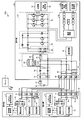
- FIG. 1 is a view showing a configuration example of an air conditioner according to an embodiment of the present invention.
- An air conditioner 100 according to the embodiment includes indoor units 1 a and 1 b and an outdoor unit 2.
- the air conditioner 100 is configured to include two indoor units, but it may be one or more.
- all the indoor units may be the same structure. That is, the plurality of indoor units 1a and the single outdoor unit 2 may constitute the air conditioner 100, and the plurality of indoor units 1b and the single outdoor unit 2 may constitute the air conditioner 100. It is also good.
- the outdoor unit 2 is also connected to an AC power supply 60 via a breaker 61.
- the indoor unit 1 a includes an indoor unit control unit 11, a power supply circuit 12, a communication circuit 13, a detection circuit 14, an opening / closing device 15, a wiring connection unit 16, a remote control signal reception unit 17, a rectification circuit 18 and an inrush current prevention element 19.
- the indoor unit control unit 11 controls each unit constituting the indoor unit 1a.
- a target to be controlled by the indoor unit control unit 11 includes the open / close device 15.
- the power supply circuit 12 generates a control power supply for operating the indoor unit control unit 11 and the communication circuit 13.
- the communication circuit 13 is a circuit for the indoor unit 1 a to communicate with the outdoor unit 2.
- the opening / closing device 15 is provided to start up the outdoor unit 2 and is closed when starting up the outdoor unit 2 and is opened in other cases. That is, in the air conditioner 100 according to the present embodiment, the power for startup is supplied from the indoor unit 1a to the outdoor unit 2 when the switching device 15 is closed.
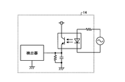
- the detection circuit 14 is a circuit for detecting that the switching device 15 has operated.
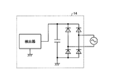
- the detection circuit 14 can be a path having the configuration shown in FIG. 2 or the configuration shown in FIG.
- the detector acquires a pulse waveform after half-wave rectification. That is, when the switching device 15 is in the closed state, the detector detects a pulse waveform.
- the detection circuit 14 configured as shown in FIG. 3 the detector acquires the DC voltage after full-wave rectification. That is, when the switching device 15 is in the closed state, the detector detects a non-zero DC voltage.
- the detection circuit 14 is not an essential component and can be omitted, when the detection circuit 14 is provided, the indoor unit whether or not the open / close device 15 operates normally according to the control of the indoor unit control unit 11 The control unit 11 can be recognized.
- the wire connection portion 16 has terminals S1 to S4 for connecting a cable that electrically connects the indoor unit 1a and the outdoor unit 2.
- the opening / closing device 15 described above is provided between the terminal S1 and the terminal S4 of the wiring connection portion 16, and the indoor unit control portion 11 is configured to short the terminal S1 and the terminal S4 when activating the outdoor unit 2.
- Controlled by The communication circuit 13 described above is connected to the terminal S2 and the terminal S3 of the wiring connection unit 16.
- the terminal S1 is a first indoor unit side terminal
- the terminal S2 is a second indoor unit side terminal
- the terminal S3 is a third indoor unit side terminal
- the terminal S4 is a fourth indoor unit side terminal.
- the remote control signal receiving unit 17 is a circuit for receiving a signal transmitted by the remote control (remote controller) 3.
- the rectifier circuit 18 converts AC power supplied from the AC power supply 60 through the outdoor unit 2 into DC power.
- the inrush current prevention element 19 is a resistor and is connected in series to the switching device 15. Specifically, one end of the rush current preventing element 19 is connected to the switching device 15, and the other end is connected to the terminal S1 of the wiring connection portion 16. The inrush current prevention element 19 is provided to suppress an inrush current flowing in the circuit when the switching device 15 is closed.
- the indoor unit 1b is configured not to include the detection circuit 14 of the indoor unit 1a, and the components of the indoor unit 1b are the same as the components of the indoor unit 1a having the same reference numerals. Therefore, the description of the details of the indoor unit 1b is omitted.
- the outdoor unit 2 includes a power supply connection unit 21, a filter circuit 22, switching devices 23 to 25, an inrush current prevention element 26, a rectifier circuit 28, a booster circuit 29, an inverter circuit 30, a compressor 32, a temperature detector 33, and a communication circuit 34.
- a power supply generation unit 35, an outdoor unit waveform generation unit 36, an outdoor unit control unit 37, and a wiring connection unit 38 are provided.
- the switching devices 23 to 25 and the inrush current prevention element 26 constitute a switching unit 27 that opens and closes a power supply path to the rectifier circuit 28.
- the rectifier circuit 28, the booster circuit 29, and the inverter circuit 30 constitute a power conversion unit 31 that generates drive power for the compressor 32.
- the switchgear 23 is a first switchgear
- the switchgear 24 is a second switchgear
- the switchgear 25 is a third switchgear.
- the power supply connection portion 21 has two terminals L and N to which an AC power supply 60 is connected.
- the terminal L is a first power supply terminal
- the terminal N is a second power supply terminal.
- the filter circuit 22 removes noise components propagating through a power supply line connecting the AC power supply 60 and the outdoor unit 2. If the noise component propagating through the power supply line is small, that is, if the noise component is at a level that does not adversely affect the operation of the air conditioner 100 and the other devices connected to the AC power supply 60, the filter circuit 22 It may be omitted.
- the switching devices 23 to 25 are provided to reduce the power consumption of the outdoor unit 2 at the time of standby.
- the switching devices 23 to 25 are connected in parallel, and one end of the switching devices 23 to 25 is connected to the terminal L of the power supply connection portion 21 via the filter circuit 22.
- the other end of each of the switching devices 23 and 24 is connected to one end of an inrush current prevention element 26 formed of a resistor.
- the other end of the inrush current protection element 26 and the other end of the switching device 25 are connected to one of two input terminals of the rectifier circuit 28.
- the initial state of the switching devices 23 to 25 is open.
- the switching device 25 is a mechanical switching device, and is configured to close the contact by the magnetic force generated by the coil when the current is supplied to the coil inside upon receiving the supply of AC power.
- the switchgears 23 and 24 may be mechanical switchgears or other switchgears.
- the switching unit 27 configured by the switching devices 23 to 25 and the rush current preventing element 26 is disposed on the power supply path on the terminal L side.
- the opening / closing unit 27 may be disposed on the supply path.
- the rectifier circuit 28 converts the AC power supplied from the AC power supply 60 into DC power and outputs the DC power.
- a booster circuit 29 is connected to the output side of the rectifier circuit 28.
- An inverter circuit 30 and a power supply generation unit 35 are connected to the output side of the booster circuit 29.
- the booster circuit 29 boosts the DC power output from the rectifier circuit 28 and supplies the DC power to the inverter circuit 30 and the power supply generation unit 35.
- the compressor 32 is connected to the output side of the inverter circuit 30.
- the inverter circuit 30 converts the DC voltage input from the booster circuit 29 into an alternating current to generate driving power for the compressor 32.
- the booster circuit 29 is not an essential component, and may be omitted.
- the compressor 32 includes a motor (not shown), and drives the motor with the power supplied from the inverter circuit 30 to compress the refrigerant flowing in the refrigerant pipe (not shown).
- the temperature detector 33 detects the temperature of the compressor 32.
- Communication circuit 34 communicates with communication circuit 13 of indoor units 1a and 1b.
- the power supply generation unit 35 converts a DC voltage input from the booster circuit 29 and generates a control power supply for operating the outdoor unit waveform generation unit 36 and the outdoor unit control unit 37.
- the power supply generation unit 35 also generates a control power supply for operating the communication circuit 33.
- the outdoor unit waveform generation unit 36 generates a PWM (Pulse Width Modulation) signal for controlling the switching elements that constitute the inverter circuit 30.
- the outdoor unit controller 37 controls the open / close devices 24 and 25.
- the wire connection portion 38 has terminals S1 to S4. Cables for electrically connecting the outdoor unit 2 and the indoor units 1a and 1b are connected to the terminals S1 to S4.
- the terminal S1 of the wiring connection portion 38 is a first connection terminal, and is connected to the terminal S1 of the wiring connection portion 16 of the indoor units 1a and 1b via a cable.
- the terminal S2 of the wiring connection portion 38 is a second connection terminal, and is connected to the terminal S2 of the wiring connection portion 16 of the indoor units 1a and 1b via a cable.
- the terminal S3 of the wiring connection portion 38 is a third connection terminal, and is connected to the terminal S3 of the wiring connection portion 16 of the indoor units 1a and 1b via a cable.
- the terminal S4 of the wiring connection portion 38 is a fourth connection terminal, and is connected to the terminal S4 of the wiring connection portion 16 of the indoor units 1a and 1b via a cable.
- the terminal S1 of the wiring connection portion 38 is connected to the terminal L of the power supply connection portion 21, and the terminal S2 of the wiring connection portion 38 is connected to the terminal N of the power supply connection portion 21. Therefore, the alternating current power from the alternating current power supply 60 is applied to the terminal S1 and the terminal S2.
- AC power supplied from the AC power supply 60 to the outdoor unit 2 is supplied to the indoor units 1a and 1b via the terminals S1 and S2 of the wiring connection portion 38.
- a communication circuit 34 is connected to the terminals S2 and S3 of the wiring connection portion 38. Further, a coil inside the switching device 23 is connected between the terminal S2 and the terminal S4 of the wiring connection portion 38.
- the indoor unit control unit 11 of the indoor units 1a and 1b can be realized by the control circuit 200 shown in FIG. 4, specifically, the processor 201 and the memory 202.
- the processor 201 is a central processing unit (CPU) (also referred to as a central processing unit, a processing unit, an arithmetic unit, a microprocessor, a microcomputer, a processor, or a digital signal processor (DSP)).
- the memory 202 is, for example, non-volatile, such as random access memory (RAM), read only memory (ROM), flash memory, erasable programmable read only memory (EPROM), and EEPROM (registered trademark) (electrically erasable programmable read only memory). Or volatile semiconductor memory, including magnetic disks.
- the indoor unit control unit 11 is realized by the memory 202 holding a program in which the process executed by the indoor unit control unit 11 is described, and the processor 201 reading out and executing this program.
- the indoor unit control unit 11 may be realized by a processing circuit as dedicated hardware.
- the processing circuit may be a single circuit, a complex circuit, a programmed processor, a parallel programmed processor, an application specific integrated circuit (ASIC), a field programmable gate array (FPGA), or a combination thereof. .
- the outdoor unit waveform generation unit 36 and the outdoor unit control unit 37 of the outdoor unit 2 shown in FIG. 1 can also be realized by the same hardware as the indoor unit control unit 11.
- the air conditioner 100 can shift the outdoor unit 2 to the low standby power state by opening the switching devices 24 and 25 of the outdoor unit 2 when the operation is stopped. is there.
- the low standby power state refers to a state in which the power conversion unit 31 stops the operation without power supply to the rectifier circuit 28 of the outdoor unit 2 and power consumption is suppressed low.
- the outdoor unit 2 when the outdoor unit 2 is in the low standby power state, the outdoor unit 2 can recover from the low standby power state by closing the opening / closing device 15 with the indoor unit 1a. .
- the operation of the air conditioner 100 specifically, the operation when the outdoor unit 2 starts up, that is, the operation when the outdoor unit 2 recovers from the low standby power state, and the outdoor unit 2 from the operating state is low
- the operation in the case of transition to the standby power state will be described.
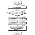
- FIG. 5 is a flowchart showing an example of the operation of the outdoor unit 2 of the air conditioner 100 returning from the low standby power state.
- the operation shown in FIG. 5 starts when the breaker 61 connected to the outdoor unit 2 is turned on and power is supplied from the AC power supply 60 to the outdoor unit 2.
- the breaker 61 When the breaker 61 is turned on and turned on, supply of power from the AC power supply 60 to the indoor units 1a and 1b is started. Specifically, electric power is supplied from the AC power supply 60 to the indoor units 1a and 1b via the power supply connection portion 21 of the outdoor unit 2 and the terminals S1 and S2 of the wiring connection portion 38.
- the rectifier circuit 18 converts alternating current to direct current
- the power supply circuit 12 generates control power
- power to the indoor unit control unit 11 and the communication circuit 13 Supply When the indoor unit control unit 11 and the communication circuit 13 receive power supply from the power supply circuit 12 and the indoor units 1a and 1b start operating (step S11), the air conditioner 100 enters a standby state.
- the switching devices 23, 24 and 25 of the outdoor unit 2 are in the released state, and power is not supplied to the rectifying circuit 28 of the outdoor unit 2. That is, the outdoor unit 2 is in the low standby power state.
- the indoor units 1a and 1b check whether a start signal has been received from the remote control 3 (step S12).
- the start signal here is a signal instructing the air conditioner 100 to start.
- the remote control 3 transmits an activation signal, for example, when an operation for starting driving is received from the user.
- step S12 When the indoor units 1a and 1b do not receive the start signal (step S12: No), step S12 is repeated.
- the remote control signal receiving unit 17 receives the signal transmitted from the remote control 3, and the indoor unit control unit 11 determines whether the signal received by the remote control signal receiving unit 17 is a start signal or not. Determine
- step S12 When the indoor units 1a and 1b receive the start signal (step S12: Yes), the open / close device 15 is closed (step S13), and the open / close device 23 of the outdoor unit 2 is closed (step S14). That is, when the switching device 15 is closed, the terminals S1 and S4 of the wiring connection portion 16 are shorted. Along with this, current flows in the coil inside the switchgear 23 of the outdoor unit 2 to operate the contact of the switchgear 23 and the switchgear 23 is closed. The indoor unit controller 11 performs an operation of closing the opening / closing device 15.
- the switching device 23 When the switching device 23 is closed, the power from the AC power supply 60 is supplied to the rectifier circuit 28 via the switching device 23 and the rush current prevention element 26. Then, the electric power converted into direct current by the rectifier circuit 28 is supplied to the inverter circuit 30 and the power supply generation unit 35 via the booster circuit 29. As a result, the power generation unit 35 starts generation of the control power, and the outdoor unit waveform generation unit 36, the outdoor unit control unit 37 and the communication circuit 34 receive the supply of the control power generated by the power generation unit 35 and operate. Start.
- the outdoor unit controller 37 When starting operation, the outdoor unit controller 37 first closes the switching device 24 and then closes the switching device 25 (step S15).
- the reason why the switching devices 24 and 25 are operated in this order is that the inrush current flowing into the rectifier circuit 28 at the start of the power supply is connected in series with the switching device 24 by closing the switching device 24 first. This is suppressed by the action of the inrush current preventing element 26. Thereafter, when the switching device 25 is closed, power is supplied to the rectifier circuit 28 without passing through the inrush current preventing element 26, and power is wasted in the inrush current preventing element 26. It can prevent.
- the outdoor unit control unit 37 generates a signal indicating that the power conversion unit 31 has started operation and the outdoor unit 2 has been activated, and transmits the signal to the indoor units 1a and 1b via the communication circuit 34.
- a signal indicating that the outdoor unit 2 has been activated is received by the communication circuit 13 of the indoor units 1a and 1b, and is delivered to the indoor unit control unit 11.
- the indoor unit control unit 11 receives a signal indicating that the outdoor unit 2 has been activated
- the indoor unit control unit 11 opens the open / close device 15.
- the indoor unit control unit 11 in which the opening / closing device 15 is closed in response to the reception of the start signal from the remote control 3 opens the opening / closing device 15.
- the other indoor unit control units 11 do nothing even if they receive a signal indicating that the outdoor unit 2 has been activated.
- the switching device 15 When the switching device 15 is in the open state, the terminal S1 and the terminal S4 of the wiring connection portion 16 are in the open state. As a result, the current does not flow to the coil inside the opening / closing device 23 of the outdoor unit 2, so the opening / closing device 23 is in the open state.
- the outdoor unit 2 is switched to the low standby power state for a predetermined time (for example, 30 Even when a minute has elapsed, the low standby power state may be restored.
- FIG. 6 is a flowchart showing an example of an operation of the outdoor unit 2 of the air conditioner 100 shifting from the operating state to the low standby power state.
- the operation shown in FIG. 6 starts when the indoor unit 1a or 1b receives an operation stop signal from the remote control 3 while the air conditioner 100 is operating.
- the remote controller 3 transmits an operation stop signal, for example, when an operation for stopping the operation is received from the user.
- the indoor units 1a and 1b stop the air conditioning operation and transmit a stop signal to the outdoor unit 2 (step S21).
- the air conditioning operation is an operation directly related to air conditioning, such as a blowing operation and an adjustment operation of the wind direction, an operation in which the communication circuit 13 communicates with the outdoor unit 2, and the remote control signal receiving unit 17 receives a signal from the remote control 3 Motion etc. are not included.
- the indoor unit control unit 11 stops the air conditioning operation, generates a stop signal, and transmits the stop signal to the outdoor unit 2 via the communication circuit 13. Send.
- the outdoor unit 2 When the outdoor unit 2 receives the stop signal transmitted by the indoor unit 1a or 1b in step S21, the outdoor unit 2 confirms whether or not transition to the low standby power state is possible (step S22).
- the outdoor unit controller 37 determines whether the outdoor unit 2 can shift to the low standby power state.
- the outdoor unit control unit 37 determines that transition to the low standby power state is possible when a certain condition is satisfied.
- the outdoor unit control unit 37 waits low based on, for example, the state of the indoor units 1a and 1b, the prediction of the outside air temperature change, and the compressor temperature that is the temperature detected by the temperature detector 33 of the outdoor unit 2. Determine if transition to power state is possible.
- the outdoor unit control unit 37 stops the air conditioning operation of all the indoor units 1a and 1b, and the preheating operation of the compressor 32 is performed based on the prediction of the outside air temperature change and the compressor temperature. If it is determined that it is not necessary, transition to the low standby power state is enabled.
- the preheating operation of the compressor 32 is an operation of adjusting the temperature of the compressor 32 by supplying current to the coil of the motor constituting the compressor 32 to generate heat.
- step S22: No If the outdoor unit 2 can not shift to the low standby power state (step S22: No), the outdoor unit 2 repeats the confirmation process until the transition to the low standby power state becomes possible.
- step S22: Yes the open / close devices 24 and 25 are opened in the reverse order to the case of recovery from the low standby power state. That is, the outdoor unit controller 37 first opens the switching device 25 and then opens the switching device 24 (step S23). As a result, the outdoor unit 2 shifts to the low standby power state (step S24).
- the outdoor unit 2 and the indoor units 1a and 1b are connected by four connection lines, and the first connection line of the four connection lines and Power is supplied from the outdoor unit 2 to the indoor units 1a and 1b using the second connection line, and the indoor units 1a and 1b open and close for starting the outdoor unit 2 using the fourth connection line. Operate the device.
- the outdoor unit 2 and the indoor units 1a and 1b communicate with each other via the third connection line.
- FIG. 7 is a diagram showing another configuration example of the air conditioner according to the embodiment of the present invention.
- the air conditioner 100a shown in FIG. 7 is the outdoor unit 2a of the air conditioner 100 shown in FIG.
- the outdoor unit 2 a has a configuration in which the switching device 39 and the rush current preventing element 40 are added to the outdoor unit 2.
- the switching device 39 and the rush current preventing element 40 are connected in series, and provided between the terminal S1 and the terminal S4 of the wiring connection portion 38. Specifically, one end of the switching device 39 is connected to the terminal S4, and the other end of the switching device 39 is connected to one end of the rush current prevention element 40. Further, the other end of the inrush current preventing element 40 is connected to the terminal S1.
- the switchgear 39 is a fourth switchgear in the outdoor unit 2a.
- the configuration other than the opening / closing device 39 of the outdoor unit 2a and the rush current preventing element 40 is the same as that of the outdoor unit 2, and therefore the description of the same configuration will be omitted.
- the outdoor unit 2a can notify the indoor unit 1a of the transition to the low standby power state using the opening / closing device 39.
- the outdoor unit controller 37 starts the operation and closes the switching devices 24 and 25 and then closes the switching device 39. Further, when shifting to the low standby power state, the outdoor unit control unit 37 also brings the open / close device 39 into an open state together with the open / close devices 24 and 25.
- the indoor unit 1a may detect the state of the switching device 39 using the detection circuit 14 and detect that the outdoor unit 2a has shifted to the low standby power state.
- the configuration shown in the above embodiment shows an example of the contents of the present invention, and can be combined with another known technique, and one of the configurations is possible within the scope of the present invention. Parts can be omitted or changed.
Abstract
Description
図1は、本発明の実施の形態にかかる空気調和機の構成例を示す図である。実施の形態にかかる空気調和機100は、室内機1aおよび1bと、室外機2とを備える。図1では、空気調和機100が室内機を2台備える構成としているが1台以上であればよい。また、室内機1aの構成と室内機1bの構成が異なる場合の例を説明しているが、複数の室内機が全て同じ構成であってもよい。すなわち、複数の室内機1aと単一の室外機2とが空気調和機100を構成してもよいし、複数の室内機1bと単一の室外機2とが空気調和機100を構成してもよい。また、室外機2は、ブレーカ61を介して交流電源60に接続される。 Embodiment.
FIG. 1 is a view showing a configuration example of an air conditioner according to an embodiment of the present invention. An
まず、室外機2が低待機電力状態から復帰する場合の動作について、図5を参照しながら説明する。図5は、空気調和機100の室外機2が低待機電力状態から復帰する動作の一例を示すフローチャートである。 (Operation when the outdoor unit 2 recovers from the low standby power state)
First, the operation when the outdoor unit 2 recovers from the low standby power state will be described with reference to FIG. FIG. 5 is a flowchart showing an example of the operation of the outdoor unit 2 of the
次に、室外機2が動作状態から低待機電力状態に移行する場合の動作について、図6を参照しながら説明する。図6は、空気調和機100の室外機2が動作状態から低待機電力状態に移行する動作の一例を示すフローチャートである。 (Operation when the outdoor unit 2 shifts from the operating state to the low standby power state)
Next, the operation in the case where the outdoor unit 2 shifts from the operating state to the low standby power state will be described with reference to FIG. FIG. 6 is a flowchart showing an example of an operation of the outdoor unit 2 of the
Claims (7)
- 室内機および室外機を備える空気調和機であって、
前記室外機は、
前記室内機が接続される第1の接続端子、第2の接続端子、第3の接続端子および第4の接続端子と、
電力変換部と、
前記第1の接続端子と前記電力変換部との間に設けられた開閉部と、
を備え、
前記室内機は、
前記第1の接続端子と接続される第1の室内機側端子、前記第2の接続端子と接続される第2の室内機側端子、前記第3の接続端子と接続される第3の室内機側端子、および前記第4の接続端子と接続される第4の室内機側端子と、
前記第1の室内機側端子と前記第4の室内機側端子との間に設けられた開閉機器と、
を備え、
前記開閉部は、
前記第2の接続端子および前記第4の接続端子から電力の供給を受けているときに閉状態となる第1の開閉機器と、
前記第1の開閉機器と並列に接続された第2の開閉機器と、
を備え、
前記第1の接続端子および前記第2の接続端子に交流電力が印加され、
前記室外機および前記室内機は、前記第3の接続端子と前記第3の室内機側端子とを接続する接続線を介して通信を行い、
前記室内機は、前記電力変換部が動作を停止している状態である低待機電力状態のときに起動信号を受け取ると前記開閉機器を閉状態とし、前記電力変換部が動作を開始した後に前記開閉機器を開状態とし、
前記室外機は、前記第1の開閉機器が閉状態となり前記電力変換部に対して交流電力の供給が開始されると前記第2の開閉機器を閉状態とする、
ことを特徴とする空気調和機。 An air conditioner comprising an indoor unit and an outdoor unit, comprising:
The outdoor unit is
A first connection terminal to which the indoor unit is connected, a second connection terminal, a third connection terminal, and a fourth connection terminal;
A power converter,
An open / close unit provided between the first connection terminal and the power conversion unit;
Equipped with
The indoor unit is
A first indoor unit side terminal connected to the first connection terminal, a second indoor unit side terminal connected to the second connection terminal, and a third indoor unit connected to the third connection terminal A machine-side terminal, and a fourth indoor unit-side terminal connected to the fourth connection terminal;
An opening / closing device provided between the first indoor unit side terminal and the fourth indoor unit side terminal;
Equipped with
The opening and closing unit is
A first switchgear that is closed when power is supplied from the second connection terminal and the fourth connection terminal;
A second switching device connected in parallel with the first switching device;
Equipped with
AC power is applied to the first connection terminal and the second connection terminal,
The outdoor unit and the indoor unit communicate via a connection line connecting the third connection terminal and the third indoor unit side terminal,
The indoor unit closes the switchgear when the start signal is received in the low standby power state, which is a state in which the power conversion unit stops operation, and the power conversion unit starts the operation. Open the switchgear,
The outdoor unit closes the second switching device when the first switching device is closed and supply of AC power to the power conversion unit is started.
An air conditioner characterized by - 前記室外機は、前記第2の開閉機器を開状態から閉状態にすると、前記電力変換部が動作を開始したことを示す信号を前記室内機へ送信し、
前記室内機は、前記電力変換部が動作を開始したことを示す前記信号を受信すると前記開閉機器を開状態とする、
ことを特徴とする請求項1に記載の空気調和機。 The outdoor unit transmits a signal indicating that the power conversion unit has started operation to the indoor unit when the second open / close device is closed from the open state.
When the indoor unit receives the signal indicating that the power conversion unit has started operation, the indoor unit opens the switching device.
The air conditioner according to claim 1, characterized in that. - 前記室外機は、一定の条件を満たした場合に前記第2の開閉機器を開状態にして前記室外機を前記低待機電力状態に移行させる、
ことを特徴とする請求項1または2に記載の空気調和機。 When the outdoor unit satisfies a certain condition, the second opening / closing device is opened to shift the outdoor unit to the low standby power state.
The air conditioner according to claim 1 or 2, characterized in that. - 前記開閉機器は、
一端が前記第1の開閉機器および前記第2の開閉機器に接続され、他端が前記電力変換部に接続された突入電流防止素子と、
前記第1の開閉機器、前記第2の開閉機器および前記突入電流防止素子と並列に接続された第3の開閉機器と、
を備え、
前記室外機は、
前記第2の開閉機器を閉状態にした後、前記第3の開閉機器を閉状態にする、
ことを特徴とする請求項1から3のいずれか一つに記載の空気調和機。 The switchgear is
A rush current preventing element having one end connected to the first switching device and the second switching device and the other end connected to the power conversion unit;
A third switching device connected in parallel with the first switching device, the second switching device, and the inrush current prevention element;
Equipped with
The outdoor unit is
After closing the second switching device, the third switching device is closed.
The air conditioner according to any one of claims 1 to 3, characterized in that. - 前記室外機は、
前記第2の開閉機器を開状態にする場合、前記第3の開閉機器を先に開状態にしてから前記第2の開閉機器を開状態にする、
ことを特徴とする請求項4に記載の空気調和機。 The outdoor unit is
When the second switching device is opened, the third switching device is opened first and then the second switching device is opened.
The air conditioner according to claim 4, characterized in that. - 前記室外機は、
前記第1の接続端子と前記第4の接続端子との間に設けられた第4の開閉機器、
を備え、
前記低待機電力状態の場合と前記低待機電力状態ではない場合とで前記第4の開閉機器の状態を変更することにより前記低待機電力状態となったことを前記室内機に通知する、
ことを特徴とする請求項1から5のいずれか一つに記載の空気調和機。 The outdoor unit is
A fourth switchgear provided between the first connection terminal and the fourth connection terminal;
Equipped with
Informing the indoor unit that the low standby power state has been entered by changing the state of the fourth switching device between the low standby power state and the low standby power state.
The air conditioner according to any one of claims 1 to 5, characterized in that. - 前記室外機には前記室内機が複数接続されることを特徴とする請求項1から6のいずれか一つに記載の空気調和機。 The air conditioner according to any one of claims 1 to 6, wherein a plurality of the indoor units are connected to the outdoor unit.
Priority Applications (6)
| Application Number | Priority Date | Filing Date | Title |
|---|---|---|---|
| PCT/JP2017/027086 WO2019021397A1 (en) | 2017-07-26 | 2017-07-26 | Air conditioner |
| CN201780093379.7A CN110959092B (en) | 2017-07-26 | 2017-07-26 | Air conditioner |
| US16/616,676 US11486596B2 (en) | 2017-07-26 | 2017-07-26 | Air conditioner |
| EP17918831.3A EP3660406B1 (en) | 2017-07-26 | 2017-07-26 | Air conditioner |
| JP2019532272A JP6732132B2 (en) | 2017-07-26 | 2017-07-26 | Air conditioner |
| AU2017424871A AU2017424871B2 (en) | 2017-07-26 | 2017-07-26 | Air conditioner |
Applications Claiming Priority (1)
| Application Number | Priority Date | Filing Date | Title |
|---|---|---|---|
| PCT/JP2017/027086 WO2019021397A1 (en) | 2017-07-26 | 2017-07-26 | Air conditioner |
Publications (1)
| Publication Number | Publication Date |
|---|---|
| WO2019021397A1 true WO2019021397A1 (en) | 2019-01-31 |
Family
ID=65040066
Family Applications (1)
| Application Number | Title | Priority Date | Filing Date |
|---|---|---|---|
| PCT/JP2017/027086 WO2019021397A1 (en) | 2017-07-26 | 2017-07-26 | Air conditioner |
Country Status (6)
| Country | Link |
|---|---|
| US (1) | US11486596B2 (en) |
| EP (1) | EP3660406B1 (en) |
| JP (1) | JP6732132B2 (en) |
| CN (1) | CN110959092B (en) |
| AU (1) | AU2017424871B2 (en) |
| WO (1) | WO2019021397A1 (en) |
Cited By (1)
| Publication number | Priority date | Publication date | Assignee | Title |
|---|---|---|---|---|
| WO2020228134A1 (en) * | 2019-05-10 | 2020-11-19 | 广东美的制冷设备有限公司 | Communication control method and apparatus for air conditioner, and air conditioner |
Families Citing this family (3)
| Publication number | Priority date | Publication date | Assignee | Title |
|---|---|---|---|---|
| CN108168048B (en) * | 2017-11-16 | 2020-04-24 | 青岛海尔空调器有限总公司 | Method and device for identifying air conditioner circuit and air conditioner |
| CN112032981B (en) * | 2020-07-24 | 2021-10-22 | 广东积微科技有限公司 | Air conditioner indoor and outdoor unit communication circuit and air conditioner |
| CN114811861B (en) * | 2022-03-30 | 2023-11-24 | 青岛海尔空调电子有限公司 | Central air conditioner control method and central air conditioner |
Citations (5)
| Publication number | Priority date | Publication date | Assignee | Title |
|---|---|---|---|---|
| JP2008101895A (en) * | 2006-10-18 | 2008-05-01 | Samsung Electronics Co Ltd | Air conditioner and control method therefor |
| JP2010121810A (en) * | 2008-11-18 | 2010-06-03 | Panasonic Corp | Communication control device for air conditioner |
| JP2014013143A (en) * | 2013-10-24 | 2014-01-23 | Daikin Ind Ltd | Air conditioner |
| JP2014152968A (en) | 2013-02-06 | 2014-08-25 | Mitsubishi Electric Corp | Air conditioner |
| JP2016090183A (en) * | 2014-11-07 | 2016-05-23 | 三菱電機株式会社 | Air conditioner |
Family Cites Families (12)
| Publication number | Priority date | Publication date | Assignee | Title |
|---|---|---|---|---|
| JP3730808B2 (en) * | 1999-06-03 | 2006-01-05 | 株式会社日立製作所 | Air conditioner |
| JP2004190889A (en) * | 2002-12-09 | 2004-07-08 | Sharp Corp | Air-conditioner |
| JP3806882B2 (en) * | 2004-11-29 | 2006-08-09 | ダイキン工業株式会社 | Air conditioner |
| JP5241585B2 (en) * | 2009-04-06 | 2013-07-17 | 三菱電機株式会社 | Air conditioner |
| KR101706102B1 (en) * | 2010-02-12 | 2017-02-27 | 삼성전자주식회사 | Air conditioner |
| KR101858938B1 (en) * | 2011-09-19 | 2018-06-29 | 삼성전자주식회사 | Air conditioner |
| JP5772588B2 (en) * | 2011-12-28 | 2015-09-02 | ダイキン工業株式会社 | Air conditioner |
| WO2013099277A1 (en) * | 2011-12-28 | 2013-07-04 | ダイキン工業株式会社 | Air conditioning device |
| JP5648700B2 (en) * | 2013-02-08 | 2015-01-07 | ダイキン工業株式会社 | Power consumption reduction device |
| JP5984732B2 (en) * | 2013-04-09 | 2016-09-06 | 三菱電機株式会社 | Air conditioner |
| JP6157374B2 (en) * | 2014-02-05 | 2017-07-05 | 三菱電機株式会社 | Air conditioner |
| CN106440220B (en) * | 2016-10-12 | 2019-07-02 | 青岛海尔空调器有限总公司 | Air-conditioner standby circuit and air conditioner |
-
2017
- 2017-07-26 JP JP2019532272A patent/JP6732132B2/en active Active
- 2017-07-26 CN CN201780093379.7A patent/CN110959092B/en active Active
- 2017-07-26 US US16/616,676 patent/US11486596B2/en active Active
- 2017-07-26 WO PCT/JP2017/027086 patent/WO2019021397A1/en unknown
- 2017-07-26 AU AU2017424871A patent/AU2017424871B2/en active Active
- 2017-07-26 EP EP17918831.3A patent/EP3660406B1/en active Active
Patent Citations (5)
| Publication number | Priority date | Publication date | Assignee | Title |
|---|---|---|---|---|
| JP2008101895A (en) * | 2006-10-18 | 2008-05-01 | Samsung Electronics Co Ltd | Air conditioner and control method therefor |
| JP2010121810A (en) * | 2008-11-18 | 2010-06-03 | Panasonic Corp | Communication control device for air conditioner |
| JP2014152968A (en) | 2013-02-06 | 2014-08-25 | Mitsubishi Electric Corp | Air conditioner |
| JP2014013143A (en) * | 2013-10-24 | 2014-01-23 | Daikin Ind Ltd | Air conditioner |
| JP2016090183A (en) * | 2014-11-07 | 2016-05-23 | 三菱電機株式会社 | Air conditioner |
Non-Patent Citations (1)
| Title |
|---|
| See also references of EP3660406A4 |
Cited By (1)
| Publication number | Priority date | Publication date | Assignee | Title |
|---|---|---|---|---|
| WO2020228134A1 (en) * | 2019-05-10 | 2020-11-19 | 广东美的制冷设备有限公司 | Communication control method and apparatus for air conditioner, and air conditioner |
Also Published As
| Publication number | Publication date |
|---|---|
| AU2017424871B2 (en) | 2021-01-14 |
| US11486596B2 (en) | 2022-11-01 |
| JPWO2019021397A1 (en) | 2019-11-07 |
| EP3660406A1 (en) | 2020-06-03 |
| AU2017424871A1 (en) | 2020-01-02 |
| EP3660406A4 (en) | 2020-08-12 |
| EP3660406B1 (en) | 2023-05-24 |
| CN110959092A (en) | 2020-04-03 |
| US20200200419A1 (en) | 2020-06-25 |
| CN110959092B (en) | 2021-03-12 |
| JP6732132B2 (en) | 2020-07-29 |
Similar Documents
| Publication | Publication Date | Title |
|---|---|---|
| JP3773512B2 (en) | Motor power supply device | |
| JP6732132B2 (en) | Air conditioner | |
| JP6184391B2 (en) | Air conditioner | |
| JP5382105B2 (en) | Air conditioner | |
| JP2012107817A (en) | Air conditioning apparatus | |
| JP6037884B2 (en) | Air conditioner | |
| JP2010178594A (en) | Power supply apparatus | |
| EP3367559B1 (en) | Air conditioner | |
| JP5804009B2 (en) | Air conditioner | |
| KR102060068B1 (en) | Power transforming apparatus and air conditioner including the same | |
| JP6336209B2 (en) | Air conditioner | |
| JP2000002188A (en) | Control device of air-conditioner | |
| JP4623220B2 (en) | Power circuit | |
| JP6957756B2 (en) | Air conditioner | |
| KR101657228B1 (en) | Apparatus for controlling stand-by power of air conditioner | |
| WO2016139795A1 (en) | Air conditioning device | |
| JP2015055450A (en) | Air conditioning device | |
| JP4623221B2 (en) | Power circuit | |
| JP2006034000A (en) | Rush current prevention circuit for air conditioner | |
| JP6173488B2 (en) | Inverter device and air conditioner using inverter device | |
| JP5999141B2 (en) | Power converter | |
| JP2014532389A (en) | Home appliance including an electric motor having at least two coils, method and system for controlling the home appliance, and method of using the electric motor for powering the home appliance | |
| JPH0360396A (en) | Refrigerator unit | |
| JP5151963B2 (en) | Cooling device for heating element storage device and heating element storage device using the same | |
| CN116829882A (en) | Air conditioner |
Legal Events
| Date | Code | Title | Description |
|---|---|---|---|
| ENP | Entry into the national phase |
Ref document number: 2019532272 Country of ref document: JP Kind code of ref document: A |
|
| ENP | Entry into the national phase |
Ref document number: 2017424871 Country of ref document: AU Date of ref document: 20170726 Kind code of ref document: A |
|
| NENP | Non-entry into the national phase |
Ref country code: DE |
|
| ENP | Entry into the national phase |
Ref document number: 2017918831 Country of ref document: EP Effective date: 20200226 |