WO2019016975A1 - 水陸両用車の冷却装置、及び、水陸両用車 - Google Patents
水陸両用車の冷却装置、及び、水陸両用車 Download PDFInfo
- Publication number
- WO2019016975A1 WO2019016975A1 PCT/JP2017/044872 JP2017044872W WO2019016975A1 WO 2019016975 A1 WO2019016975 A1 WO 2019016975A1 JP 2017044872 W JP2017044872 W JP 2017044872W WO 2019016975 A1 WO2019016975 A1 WO 2019016975A1
- Authority
- WO
- WIPO (PCT)
- Prior art keywords
- cooling
- cooling water
- heat exchanger
- cooling air
- amphibian
- Prior art date
- Legal status (The legal status is an assumption and is not a legal conclusion. Google has not performed a legal analysis and makes no representation as to the accuracy of the status listed.)
- Ceased
Links
Images




Classifications
-
- B—PERFORMING OPERATIONS; TRANSPORTING
- B60—VEHICLES IN GENERAL
- B60F—VEHICLES FOR USE BOTH ON RAIL AND ON ROAD; VEHICLES CAPABLE OF TRAVELLING IN OR ON DIFFERENT MEDIA, e.g. AMPHIBIOUS VEHICLES
- B60F3/00—Amphibious vehicles, i.e. vehicles capable of travelling both on land and on water; Land vehicles capable of travelling under water
- B60F3/003—Parts or details of the vehicle structure; vehicle arrangements not otherwise provided for
- B60F3/0053—Particular devices for gas circulation, e.g. air admission, cooling, watertightness
-
- B—PERFORMING OPERATIONS; TRANSPORTING
- B60—VEHICLES IN GENERAL
- B60F—VEHICLES FOR USE BOTH ON RAIL AND ON ROAD; VEHICLES CAPABLE OF TRAVELLING IN OR ON DIFFERENT MEDIA, e.g. AMPHIBIOUS VEHICLES
- B60F3/00—Amphibious vehicles, i.e. vehicles capable of travelling both on land and on water; Land vehicles capable of travelling under water
- B60F3/0007—Arrangement of propulsion or steering means on amphibious vehicles
-
- B—PERFORMING OPERATIONS; TRANSPORTING
- B60—VEHICLES IN GENERAL
- B60K—ARRANGEMENT OR MOUNTING OF PROPULSION UNITS OR OF TRANSMISSIONS IN VEHICLES; ARRANGEMENT OR MOUNTING OF PLURAL DIVERSE PRIME-MOVERS IN VEHICLES; AUXILIARY DRIVES FOR VEHICLES; INSTRUMENTATION OR DASHBOARDS FOR VEHICLES; ARRANGEMENTS IN CONNECTION WITH COOLING, AIR INTAKE, GAS EXHAUST OR FUEL SUPPLY OF PROPULSION UNITS IN VEHICLES
- B60K11/00—Arrangement in connection with cooling of propulsion units
- B60K11/02—Arrangement in connection with cooling of propulsion units with liquid cooling
- B60K11/04—Arrangement or mounting of radiators, radiator shutters, or radiator blinds
-
- F—MECHANICAL ENGINEERING; LIGHTING; HEATING; WEAPONS; BLASTING
- F01—MACHINES OR ENGINES IN GENERAL; ENGINE PLANTS IN GENERAL; STEAM ENGINES
- F01P—COOLING OF MACHINES OR ENGINES IN GENERAL; COOLING OF INTERNAL-COMBUSTION ENGINES
- F01P11/00—Component parts, details, or accessories not provided for in, or of interest apart from, groups F01P1/00 - F01P9/00
- F01P11/02—Liquid-coolant filling, overflow, venting, or draining devices
- F01P11/0276—Draining or purging
-
- F—MECHANICAL ENGINEERING; LIGHTING; HEATING; WEAPONS; BLASTING
- F01—MACHINES OR ENGINES IN GENERAL; ENGINE PLANTS IN GENERAL; STEAM ENGINES
- F01P—COOLING OF MACHINES OR ENGINES IN GENERAL; COOLING OF INTERNAL-COMBUSTION ENGINES
- F01P3/00—Liquid cooling
- F01P3/18—Arrangements or mounting of liquid-to-air heat-exchangers
-
- F—MECHANICAL ENGINEERING; LIGHTING; HEATING; WEAPONS; BLASTING
- F01—MACHINES OR ENGINES IN GENERAL; ENGINE PLANTS IN GENERAL; STEAM ENGINES
- F01P—COOLING OF MACHINES OR ENGINES IN GENERAL; COOLING OF INTERNAL-COMBUSTION ENGINES
- F01P3/00—Liquid cooling
- F01P3/20—Cooling circuits not specific to a single part of engine or machine
-
- F—MECHANICAL ENGINEERING; LIGHTING; HEATING; WEAPONS; BLASTING
- F01—MACHINES OR ENGINES IN GENERAL; ENGINE PLANTS IN GENERAL; STEAM ENGINES
- F01P—COOLING OF MACHINES OR ENGINES IN GENERAL; COOLING OF INTERNAL-COMBUSTION ENGINES
- F01P5/00—Pumping cooling-air or liquid coolants
- F01P5/02—Pumping cooling-air; Arrangements of cooling-air pumps, e.g. fans or blowers
- F01P5/06—Guiding or ducting air to, or from, ducted fans
-
- F—MECHANICAL ENGINEERING; LIGHTING; HEATING; WEAPONS; BLASTING
- F01—MACHINES OR ENGINES IN GENERAL; ENGINE PLANTS IN GENERAL; STEAM ENGINES
- F01P—COOLING OF MACHINES OR ENGINES IN GENERAL; COOLING OF INTERNAL-COMBUSTION ENGINES
- F01P5/00—Pumping cooling-air or liquid coolants
- F01P5/10—Pumping liquid coolant; Arrangements of coolant pumps
-
- F—MECHANICAL ENGINEERING; LIGHTING; HEATING; WEAPONS; BLASTING
- F01—MACHINES OR ENGINES IN GENERAL; ENGINE PLANTS IN GENERAL; STEAM ENGINES
- F01P—COOLING OF MACHINES OR ENGINES IN GENERAL; COOLING OF INTERNAL-COMBUSTION ENGINES
- F01P9/00—Cooling having pertinent characteristics not provided for in, or of interest apart from, groups F01P1/00 - F01P7/00
- F01P9/02—Cooling by evaporation, e.g. by spraying water on to cylinders
-
- F—MECHANICAL ENGINEERING; LIGHTING; HEATING; WEAPONS; BLASTING
- F01—MACHINES OR ENGINES IN GENERAL; ENGINE PLANTS IN GENERAL; STEAM ENGINES
- F01P—COOLING OF MACHINES OR ENGINES IN GENERAL; COOLING OF INTERNAL-COMBUSTION ENGINES
- F01P5/00—Pumping cooling-air or liquid coolants
- F01P5/10—Pumping liquid coolant; Arrangements of coolant pumps
- F01P5/12—Pump-driving arrangements
- F01P2005/125—Driving auxiliary pumps electrically
-
- F—MECHANICAL ENGINEERING; LIGHTING; HEATING; WEAPONS; BLASTING
- F01—MACHINES OR ENGINES IN GENERAL; ENGINE PLANTS IN GENERAL; STEAM ENGINES
- F01P—COOLING OF MACHINES OR ENGINES IN GENERAL; COOLING OF INTERNAL-COMBUSTION ENGINES
- F01P2050/00—Applications
- F01P2050/02—Marine engines
Definitions
- the present disclosure relates to a cooling device of an amphibious vehicle capable of switching between land operation and water operation, and an amphibious vehicle equipped with the cooling device.
- amphibious vehicles were mainly for leisure purposes, but the necessity to land on isolated areas at the time of earthquake disaster etc via water navigation is also increasing, so long distance navigation on water was assumed Amphibious vehicles are required.
- Such amphibians have heat sources such as power sources such as internal combustion engines and motors, and cooling for cooling them to achieve stable operation of the amphibians.
- the device is mounted.
- Patent Document 1 in an amphibious vehicle operated in the land mode and the water mode, an air-liquid heat exchanger capable of exchanging heat with ambient air in the land mode and heat exchange with ambient water in the water mode.
- a liquid-liquid heat exchanger is disclosed.
- one type of refrigerant is generally used for one heat exchanger.
- the amphibian is equipped with two types of heat exchangers respectively corresponding to the land mode and the water mode, utilizing the characteristics operated on both land and water.
- Such a configuration uses an air-liquid heat exchanger that is superior in cooling capacity to the air-air heat exchanger in the water mode because the traveling load is large and the calorific value increases in the water mode compared to the land mode. It makes sense in point.
- mounting two types of heat exchangers results in an increase in vehicle layout restrictions due to an increase in occupied volume in the vehicle and an increase in the weight of the entire vehicle.
- At least one embodiment of the present invention has been made in view of the above-described circumstances, and is effective in improving the layout efficiency and reducing the vehicle weight while obtaining a good cooling effect according to the operating condition of the amphibian.
- An object of the present invention is to provide a cooling system of an amphibian and an amphibian equipped with the same.
- a device for cooling an amphibian A heat exchanger mounted on an amphibious vehicle, A refrigerant introduction passage which can introduce cooling air or cooling water from the outside as a refrigerant to the heat exchanger; A cooling air discharge path capable of discharging the cooling air having passed through the heat exchanger to a cooling air discharge unit communicating with the outside; And a cooling water discharge passage capable of discharging the cooling water having passed through the heat exchanger to a cooling water discharge portion communicating with the outside.
- the cooling air discharge passage and the cooling water discharge passage are formed such that at least the cooling air discharge unit and the cooling water discharge unit are independent of each other.
- cooling air discharge portion and the cooling water discharge portion are independent of each other between the cooling air discharge passage and the cooling water discharge passage through which the cooling air and cooling water having passed through the heat exchanger are discharged respectively It is formed to be. Therefore, cooling air or cooling water, which is a plurality of refrigerants introduced from the outside of the vehicle, can be taken into a single heat exchanger and used. Thereby, a heat exchanger can be operated by using cooling air as a refrigerant
- It further includes a flow path switching unit configured to be able to selectively switch the discharge destination of the refrigerant after passing through the heat exchanger to any one of the cooling air discharge path and the cooling water discharge path.
- the flow path leading to the discharge destination is either the cooling air discharge path or the cooling water discharge path It can be selectively switched to one side.
- each refrigerant can be reliably guided into the corresponding flow path.
- the flow path switching unit is An opening communicating between the cooling air discharge passage and the cooling water discharge passage; A partition plate attached to the opening from the cooling water discharge path side; A biasing member resiliently biasing the partition plate against the opening; including.
- the partition plate in the case where the cooling water does not flow into the cooling water discharge path (for example, at the time of land operation), in the flow path switching unit, the partition plate is biased to the opening by the biasing member. As a result, the opening is closed.
- the cooling air introduced from the refrigerant introduction path forms a flow path which is discharged from the cooling air discharge path to the outside without entering the cooling water discharge path.
- the partition plate is opened by the reaction force exceeding the biasing force of the biasing member acting by the cooling water having a larger specific gravity than the cooling air. The cooling water flows into the opening.
- the cooling water introduced from the refrigerant introduction path forms a flow path which is discharged from the cooling water discharge path to the outside through the opening after passing through the heat exchanger.
- the opening leading to the cooling water discharge is closed, so the cooling air is reliably guided to the cooling air discharge path.
- the opening is automatically opened by the cooling water, so the cooling water is reliably guided to the cooling water discharge path.
- Such flow path switching does not require an active device accompanied by consumption of energy like an actuator, and can reliably cut off the flow path of the refrigerant flowing into the cooling device.
- the cooling air discharge passage has a fan downstream of a branch point with the cooling water discharge passage.
- the cooling air discharge path has a fan for blowing downstream of the branch point with the cooling water discharge path
- the cooling to the heat exchanger is performed by driving the fan during land operation. It can promote the introduction or discharge of Qi.
- the cooling air discharge path in which the fan is disposed is prevented from entering the cooling water as described above, the fan is not exposed to the cooling water, and stable operation can be ensured for a long time.
- the cooling air discharge passage is located on the downstream side of a branch point with the cooling water discharge passage above the water draft line of the amphibian.
- the cooling air discharge path is located above the water line of the amphibious vehicle on the downstream side of the junction with the cooling water discharge path, the cooling air discharges even when the vehicle is operated on the water Of the passage, the vicinity of the cooling air discharge portion is not flooded, and deterioration due to corrosion can be suppressed.
- a propulsion device for generating a thrust using the cooling water after passing through the heat exchanger is disposed.
- the propulsion device by disposing the propulsion device in the cooling water discharge path, it is possible to stably generate thrust using the cooling water after passing through the heat exchanger at the time of operation on water .
- the suction of the cooling water is performed in the propulsion device, the cooling water can be more efficiently taken into the heat exchanger disposed on the upstream side, and a good cooling effect can be obtained.
- the fuel cell system further includes a bypass passage that connects the refrigerant introduction passage and the cooling water discharge passage. A part of the refrigerant flowing through the refrigerant introduction passage can be supplied to the propulsion device via the bypass passage without passing through the heat exchanger.
- the system further includes a bypass that connects the refrigerant introduction path and the cooling water discharge path.
- a bypass that connects the refrigerant introduction path and the cooling water discharge path.
- the refrigerant introduction passage may further include a pump capable of pressure-feeding the cooling water.
- the refrigerant introduction passage is further provided with a pump capable of pressure-feeding the cooling water. Therefore, for example, even under a situation where the draft line is lowered, the cooling water can be forcibly pumped up by the pump, and the cooling water can be stably supplied to the heat exchanger.
- the heat exchanger may further include a dispersal unit capable of distributing the cooling water pumped by the pump from above with respect to the heat exchanger.
- the cooling water is evenly supplied to the heat exchanger because it further comprises a scattering portion capable of scattering the cooling water pumped by the pump from above to the heat exchanger. can do. As a result, at the time of on-the-water operation, it is possible to enjoy a stable high cooling effect.
- the cooling air discharge passage and the cooling water discharge passage have a common space on the heat exchanger side,
- the common space is configured to be capable of storing the cooling water by being partitioned by a partition member, and has a drain path capable of discharging the stored cooling water.
- the heat exchanger is submerged in the cooling water stored in the common space regardless of the vehicle state at the time of operation on the water, and stably high A cooling effect can be obtained.
- the partition member extends from the floor surface of the common space to above the heat exchanger.
- the partition member since the partition member extends from the floor surface of the common space to the upper side of the heat exchanger, the cooling water can be stored to the upper side of the heat exchanger. Thereby, the heat exchanger can be reliably submerged in the cooling water stored in the common space, and a stable and high cooling effect can be obtained.
- the cooling air discharge unit is provided above the partition member.
- the cooling air discharge part since the cooling air discharge part is provided above the partition member, the cooling air discharge part can be favorably isolated from the cooling water stored in the common space.
- the drain path is configured such that the cooling water stored in the shared space is discharged by the amphibian being opened at the timing when the amphibian is switched from on-water operation to on-land operation.
- the cooling water is stored in the common space and the heat exchanger is submerged because the drain passage is closed while the vehicle is operated on the water. And if it switches at the time of land operation, a drain path will open and the cooling water stored by common space will be discharged
- the weight of the vehicle can be reduced by discharging the cooling water stored at the time of the on-the-water driving, and the cooling air used at the time of the on-the-ground driving can be taken into the empty shared space.
- the heat exchanger can be appropriately and sufficiently cooled according to the operating state (land operation or floating operation), Stable running performance can be exhibited under various environments.
- a cooling device for an amphibious vehicle effective for the efficiency of layout and reduction of the vehicle weight while obtaining a good cooling effect according to the driving state of the amphibious vehicle.
- FIG. 1 It is a schematic diagram which shows roughly the whole structure of the amphibious vehicle provided with the cooling device which concerns on one Embodiment of this invention. It is an enlarged view which shows the flow of the cooling air at the time of land operation in the cooling device concerning a 1st embodiment. In the cooling device concerning a 1st embodiment, it is an enlarged drawing showing the flow of the cooling water at the time of on-the-water operation. It is a figure which shows the cooling device which concerns on 2nd Embodiment. It is a figure which shows the cooling device which concerns on 3rd Embodiment. It is a modification of FIG. It is a figure showing a cooling device provided with a partition member and a drain way concerning one embodiment.
- FIG. 1 is a schematic view schematically showing the entire configuration of an amphibian 10 provided with a cooling device 20 according to an embodiment of the present invention.
- the amphibious vehicle 10 has a vehicle body 12 having a substantially rectangular parallelepiped shape.
- a plurality of wheels 13 to which driving force from the engine 14 is transmitted via power transmission means (not shown) are provided below the vehicle body 12 during land operation.
- the vehicle main body 12 is provided with a water propulsion device (not shown) provided with a propeller or a water jet to which the driving force from the engine 14 is transmitted through the power transmission means (not shown) during operation on the water There is.
- the amphibian 10 is configured to be able to operate on water and on land by driving the marine propulsion device by the engine 14 during floating operation and rotating the wheels 13 by the engine 14 during land operation.
- the engine 14 mounted as a power source of the amphibious vehicle 10 is cooled, for example, by circulating cooling water in a water jacket formed in a cylinder block (not shown).
- a cooling device 20 for such an engine 14 is shown, and a heat exchanger 21 for cooling the cooling water circulating through the engine 14 by heat exchange with an external refrigerant (cooling gas or cooling water).
- an external refrigerant cooling gas or cooling water
- the heat exchanger 21 exemplifies cooling by heat exchange of cooling water of the engine 14 with an external refrigerant, but the present invention is not limited to this.
- the heat exchanger may exchange heat with cooling water for the motor, or part of the cooling cycle used for air conditioning of the vehicle It is applicable also to the heat exchanger etc. which are used for the heat exchanger to comprise, an intercooler, an EGR cooler, etc.
- the water resistance during marine operation is greater than the air resistance during land operation, so the engine load increases relatively during marine operation compared to during land operation, Along with this, a greater amount of cooling is required during on-water operation. Therefore, the sizes of the refrigerant and the cooling device which are desirable for cooling the vehicle are different between the land operation and the water operation. Specifically, when air is used as a coolant when the engine load is high, if air is used as the refrigerant, the size of the heat exchanger required for cooling becomes large, so a small amount of high cooling effect can be expected, and a large amount exists around It is desirable to take in the cooling water from the outside of the vehicle as the refrigerant.
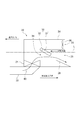
- FIG. 2 is an enlarged view showing the flow of cooling air at the time of land operation in the cooling device 20 according to the first embodiment
- FIG. 3 is a flow of cooling water at the time of on-water operation in the cooling device 20 according to the first embodiment. It is an enlarged view which shows.
- the cooling device 20 includes a heat exchanger 21 mounted on the amphibious vehicle 10, a refrigerant introduction path 22 capable of externally introducing the cooling air 50 or the cooling water 60 as a refrigerant to the heat exchanger 21, and the heat exchanger
- the cooling air discharge passage 24 which can discharge the cooling air 50 which has passed through 21 to the cooling air discharge unit 23 which communicates with the outside, and the cooling water discharge unit 25 which communicates the cooling water 60 which has passed through the heat exchanger 21 to the outside.
- a coolant discharge path 26 which can be discharged.
- the vehicle travels along the illustrated traveling direction, and along with it, the refrigerant (cooling air 50 or cooling water 60) present from the outside of the vehicle flows into the refrigerant intake port 16 (see FIG. 1). That is, the cooling air 50 is introduced into the refrigerant intake port 16 during land operation, and the cooling water 60 is introduced during floating operation.
- the refrigerant cooling air 50 or cooling water 60
- the introduction of the cooling air 50 and the cooling water 60 into the heat exchanger 21 is performed via the common single refrigerant introducing passage 22, but the cooling medium 50 and the cooling water As long as 60 can be introduced into the heat exchanger 21, it may be branched midway, or dedicated inlets for the cooling air 50 and the cooling water 60 may be provided independently.
- the refrigerant is the cooling air 50
- the refrigerant after passing through the heat exchanger 21 is discharged from the cooling air discharge unit 23 to the outside through the cooling air discharge passage 24, as shown in FIG.
- the coolant is the cooling water 60, as shown in FIG. 3
- the coolant is discharged from the cooling water discharge unit 25 to the outside through the cooling water discharge passage 26.
- the cooling air discharge part 23 and the cooling water discharge part 25 are mutually independent of the cooling air discharge passage 24 and the cooling water discharge passage 26 through which the cooling air 50 and the cooling water 60 passing through the heat exchanger 21 respectively pass. It is formed to be. Therefore, the cooling air 50 or the cooling water 60 introduced from the outside of the vehicle can be taken into the single heat exchanger 21 and used. As a result, since the cooling air 50 is used as a refrigerant during land operation and the cooling water 60 is used as a refrigerant during water operation, a single heat exchanger 21 can be used, so the number of heat exchangers mounted on a vehicle can be reduced. The vehicle layout can be improved by reducing the occupied volume of the heat exchanger 21 in the vehicle, which is effective in reducing the overall weight of the vehicle.
- the cooling device 20 in the present embodiment is a flow configured to be able to selectively switch the discharge destination of the refrigerant after passing through the heat exchanger 21 to any one of the cooling air discharge passage 24 and the cooling water discharge passage 26.
- the road switching unit 33 is further provided.
- the flow path switching unit 33 has an opening 34 communicating between the cooling air discharge passage 24 and the cooling water discharge passage 26, a partition plate 31 attached to the opening 34 from the cooling water discharge passage 26 side, and a partition plate And a biasing member 32 for biasing 31 against opening 34.
- the biasing member 32 biases the partition plate 31 in a direction opposite to the refrigerant inflow direction with a predetermined biasing force (elastic force), and is, for example, a torsion coil spring.
- the biasing force of the biasing member 32 is set to be stronger than the drag when the cooling air 50 flows into the opening 34 and to be weaker than the drag when the cooling water 60 flows into the opening 34.
- the flow path switching unit 33 in the present embodiment is configured such that the partition plate 31 is lifted along the refrigerant inflow direction only when a drag force larger than the biasing force is applied (see FIG. 3).
- the cooling air 50 flows into the vicinity of the opening 34 during land operation, since the reaction force of the cooling air 50 is smaller than the urging force of the urging member 32, the partition plate 31 Without lifting up, the opening 34 is closed, and the cooling air 50 passes through the cooling air discharge passage 24 (see FIG. 2).
- the cooling water 60 having a specific gravity larger than the cooling air 50 has a large resistance and therefore exceeds the biasing force of the biasing member 32 and the partition plate 31 is lifted. It flows in, and the cooling water 60 will pass the cooling water discharge path 26 (refer FIG. 3).
- the opening 34 leading to the cooling water discharge path 26 is closed, so the cooling air 50 is guided to the cooling air discharge path 24 It does not flow into the coolant discharge path 26.
- the cooling water 60 flows into the cooling device 20 at the time of operation on the water, the cooling water 60 is guided to the cooling water discharge path 26 because the opening 34 is automatically opened by the cooling water 60 Since the discharge passage 24 is provided above the water line, the cooling water 60 does not flow into the cooling air discharge passage 24). Therefore, the flow path switching unit 33 can appropriately switch the flow path according to the refrigerant flowing into the cooling device 20 without requiring an active drive mechanism such as an actuator.
- the cooling air discharge passage 24 further includes a fan 36 provided downstream of a branch point with the cooling water discharge passage 26.
- the fan 36 can be driven by electric power supplied from, for example, a battery (not shown) mounted on a vehicle, and generates negative pressure by being driven during land operation, thereby introducing the cooling air 50 into the heat exchanger 21 and It is configured to promote the exhaust of the cooling air 50 from the heat exchanger 21.
- the fan 36 is disposed downstream of the branch point of the cooling air discharge path 24 with the cooling water discharge path 26 (near the cooling air discharge portion 23).
- the position where the fan 36 is disposed is the vicinity of the cooling air discharge portion 23 in the cooling air discharge path 24 and is an area where the intrusion of the cooling water 60 is prevented as described above. Therefore, the fan 36 is not exposed to the cooling water 60 even when operated on the water, so that deterioration due to corrosion or the like is suppressed, and stable operation over a long period of time is possible.
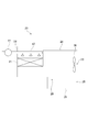
- FIG. 4 is a view showing a cooling device 20 according to the second embodiment.
- components corresponding to the above-described embodiment will be denoted by the same reference numerals, and overlapping descriptions will be omitted unless otherwise specified.
- the cooling device 20 includes a propulsion device 38 provided in the cooling water discharge passage 26.
- the propulsion device 38 is an element that constitutes a part of a marine propulsion device that is a power source when driving on the water, and, for example, cooling water after passing through the heat exchanger 21 by obtaining driving force from the engine 14 of the vehicle. To generate thrust F.
- the propulsion device 38 is, for example, a screw or a water jet.
- the cooling water 60 flows into the cooling device 20 and a flow from the heat exchanger 21 to the cooling water discharge portion 25 is generated. Further promoted by Generally, the amount of the cooling water 60 flowing into the cooling device 20 is generally lower when the vehicle is driven on the water and the speed is reduced because the vehicle turns or when a strong wind reverse to the traveling direction of the vehicle is blowing. It may be less than when driving on the water. In such a situation, although the heat exchanger 21 is in a high load state such as in-sea operation, it is conceivable that the inflow of the cooling water 60 becomes insufficient and it becomes difficult to secure a necessary amount of cooling.
- the propulsion device 38 is also used in an operating situation in which the introduction amount of the cooling water 60 to the heat exchanger 21 tends to be insufficient as described above.
- the cooling water 60 can be forcibly taken.
- the intake of the cooling water 60 to the heat exchanger 21 can be stably ensured, and the necessary amount of cooling can be sufficiently ensured.
- the cooling device 20 further includes a bypass passage 39 communicating the refrigerant introduction passage 22 and the cooling water discharge passage 26. Therefore, a part of the cooling water 60 flowing through the refrigerant introduction passage 22 is configured to be able to be supplied to the propulsion device 38 via the bypass passage 39 without passing through the heat exchanger 21.
- the above-described propulsion device 38 operates by absorbing a certain amount of water and generates thrust F.
- the propulsion device 38 is sufficient with only the cooling water 60 that has passed the heat exchanger 21. It may be difficult to secure the amount of water needed to generate the thrust. Therefore, in the present embodiment, the provision of the bypass passage 39 can secure an extra amount of water necessary for the propulsion device 38 via the bypass passage 39, so that stable propulsion performance can be obtained.
- the bypass path 39 when the land operation is switched to the water operation, it takes some time for the cooling water 60 to reach the empty cooling water discharge path 26. However, by providing the bypass path 39 in this way, the time is taken It is possible to shorten and complete the transition to marine operation at an earlier timing.
- the bypass passage 39 may be configured to connect the cooling water discharge passage 26 with the outside of the vehicle. At that time, for example, by using a pump that can be driven by electric power supplied from a battery (not shown) mounted on the vehicle, the cooling water 60 is pumped to the cooling water discharge path 26 from the outside of the vehicle It is also good.
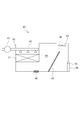
- FIG. 5 is a view showing a cooling device 20 according to a third embodiment.
- components corresponding to the above-described embodiment will be denoted by the same reference numerals, and overlapping descriptions will be omitted unless otherwise specified.
- the cooling device 20 further includes a pump 41 capable of pressure-feeding the cooling water 60 to the refrigerant introduction passage 22.
- a pump 41 capable of pressure-feeding the cooling water 60 to the refrigerant introduction passage 22.
- a distribution unit 42 capable of distributing the cooling water 60 pumped by the pump 41 from above to the heat exchanger 21 is provided.
- the cooling water 60 can be supplied evenly to the heat exchanger 21 regardless of the driving condition of the vehicle. As a result, during operation on water, stable and good cooling can be obtained.
- the cooling water is pumped up by the pump 41 at the time of operation on the water, flows in from the upper side to the heat exchanger 21, and after adding the heat exchanger 21, the opening 28 flows downward by its own weight. And is discharged to the cooling water discharge passage 26.
- the cooling air 50 is supplied to the heat exchanger 21 via the refrigerant introduction passage 22, and after passing through the heat exchanger 21, it is cooled by the fan 36 provided downstream of the cooling air discharge passage 24. The air is discharged from the air discharge unit 23.
- the cooling air discharge passage 24 and the cooling water discharge passage 26 are configured independently, but as shown in FIG. 6, the cooling water discharge passage 26 is omitted, and the cooling air discharge portion 23 and Only the cooling water discharger 25 may be configured to be independent. With such a configuration, the internal structure of the cooling device 20 can be simplified.
- FIG. 7 is a view showing a cooling device 20 according to the fourth embodiment.
- components corresponding to the above-described embodiment will be denoted by the same reference numerals, and overlapping descriptions will be omitted unless otherwise specified.
- the cooling air discharge passage 24 and the cooling water discharge passage 26 have a common space 44 on the heat exchanger 21 side.
- the common space 44 is configured to be capable of storing the cooling water 60 by being partitioned by the partition member 45.
- a drain passage 46 is provided in the common space 44, and the cooling water 60 stored in the common space 44 can be discharged.
- the drain passage 46 is configured to communicate with, for example, the outside of the vehicle.
- the heat exchanger 21 in order to secure a sufficient amount of cooling during operation on the water, it is preferable to dispose the heat exchanger 21 below the water surface. According to the present embodiment, by storing the cooling water 60 in the common space 44, the heat exchanger 21 can be disposed below the water surface for the stored cooling water 60 regardless of the vehicle state during the on-water driving. Thereby, a sufficient amount of cooling can be stably obtained.
- the partition member 45 that partitions the common space 44 extends from the floor surface of the common space 44 to above the heat exchanger 21. Therefore, it is possible to store sufficient cooling water for completely immersing the heat exchanger 21 in the common space 44 at the time of operation on the water.
- cooling air discharge unit 23 is provided above the partition member 45. Therefore, the cooling air discharge portion 23 can be well isolated from the cooling water stored in the common space 44 even during floating operation, and corrosion can be effectively prevented.
- drain passage 46 is opened at the timing when the amphibian 10 switches from on-water operation to on-land operation, whereby the cooling water 60 stored in the common space 44 is discharged.
- the drain passage 46 since the drain passage 46 is closed while the vehicle is operated on the water, the cooling water 60 is stored in the common space 44, but when switched on land, the drain passage 46 is opened, The cooling water 60 stored in the common space 44 is discharged. As a result, the cooling air 50 can be taken into the area occupied by the cooling water in the common space 44.
- a representation representing a relative or absolute arrangement such as “in a direction”, “along a direction”, “parallel”, “orthogonal”, “center”, “concentric” or “coaxial”
- a representation representing a relative or absolute arrangement such as “in a direction”, “along a direction”, “parallel”, “orthogonal”, “center”, “concentric” or “coaxial”
- expressions that indicate that things such as “identical”, “equal” and “homogeneous” are equal states not only represent strictly equal states, but also have tolerances or differences with which the same function can be obtained. It also represents the existing state.
- expressions representing shapes such as a square shape and a cylindrical shape not only indicate shapes such as a square shape and a cylindrical shape in a geometrically strict sense, but also within the range where the same effect can be obtained. Also, the shape including the uneven portion, the chamfered portion, and the like shall be indicated. Moreover, in the present specification, the expressions “comprising”, “including” or “having” one component are not exclusive expressions excluding the presence of other components.
Landscapes
- Engineering & Computer Science (AREA)
- Chemical & Material Sciences (AREA)
- Combustion & Propulsion (AREA)
- Mechanical Engineering (AREA)
- General Engineering & Computer Science (AREA)
- Transportation (AREA)
- Physics & Mathematics (AREA)
- Thermal Sciences (AREA)
- Cooling, Air Intake And Gas Exhaust, And Fuel Tank Arrangements In Propulsion Units (AREA)
Abstract
水陸両用車の冷却装置は、水陸両用車に搭載された熱交換器と、前記熱交換器に対して冷媒として冷却気又は冷却水を外部から導入可能な冷媒導入路と、前記熱交換器を通過した前記冷却気を、外部に連通する冷却気排出部に排出可能な冷却気排出路と、前記熱交換器を通過した前記冷却水を、外部に連通する冷却水排出部に排出可能な冷却水排出路とを備え、前記冷却気排出路及び前記冷却水排出路は、少なくとも前記冷却気排出部及び前記冷却水排出部が互いに独立するように形成される。
Description
本開示は、陸上運転及び水上運転を切替可能な水陸両用車の冷却装置、及び、当該冷却装置を搭載する水陸両用車に関する。
一般に、水陸両用車はレジャー目的を主としたものであったが、震災時などに孤立した地域へ水上航行を経由して上陸する必要性等も高まり、水上での長距離航行を想定した水陸両用車が求められている。このような水陸両用車は、内燃機関や電動機のような動力源をはじめとする発熱源を有しており、水陸両用車の安定的な動作を実現するために、これらを冷却するための冷却装置が搭載される。
特許文献1には、陸上モードと水上モードで運転される水陸両用車において、陸上モード時に周囲の空気と熱交換可能な空気―液体熱交換器と、水上モード時に周囲の水と熱交換可能な液体―液体熱交換器とを搭載したものが開示されている。
乗用車や船舶等、通常の乗り物における冷却装置では、一つの熱交換器に対して一種類の冷媒が用いられるのが一般的である。上述の特許文献1では、水陸両用車は陸上と水上との両方で運用される特性を利用して、陸上モードと水上モードとに夫々応じた2種類の熱交換器を搭載している。このような構成は、水上モードでは陸上モードに比べて走行負荷が大きく発熱量が増えるため、水上モードでは、空気-空気熱交換器に比べて冷却能力に優れる空気-液体熱交換器を利用する点で理にかなっている。しかしながら、2種類の熱交換器を搭載することは、車両における占有容積が増えることによって車両レイアウトの制約が増してしまうことや、車両全体の重量増加を招いてしまう。
本発明の少なくとも一つの実施形態は上述の事情に鑑みてなされたものであり、水陸両用車の運転状態に応じて良好な冷却効果を得つつ、レイアウトの効率化及び車両重量の低減に有効な水陸両用車の冷却装置及びこれを備えた水陸両用車を提供することを目的とする。
(1)本発明の幾つかの実施形態に係る水陸両用車の冷却装置は、
水陸両用車に搭載された熱交換器と、
前記熱交換器に対して冷媒として冷却気又は冷却水を外部から導入可能な冷媒導入路と、
前記熱交換器を通過した前記冷却気を、外部に連通する冷却気排出部に排出可能な冷却気排出路と、
前記熱交換器を通過した前記冷却水を、外部に連通する冷却水排出部に排出可能な冷却水排出路と
を備え、
前記冷却気排出路及び前記冷却水排出路は、少なくとも前記冷却気排出部及び前記冷却水排出部が互いに独立するように形成される。
水陸両用車に搭載された熱交換器と、
前記熱交換器に対して冷媒として冷却気又は冷却水を外部から導入可能な冷媒導入路と、
前記熱交換器を通過した前記冷却気を、外部に連通する冷却気排出部に排出可能な冷却気排出路と、
前記熱交換器を通過した前記冷却水を、外部に連通する冷却水排出部に排出可能な冷却水排出路と
を備え、
前記冷却気排出路及び前記冷却水排出路は、少なくとも前記冷却気排出部及び前記冷却水排出部が互いに独立するように形成される。
上記(1)の構成によれば、熱交換器を通過した冷却気及び冷却水がそれぞれ排出される冷却気排出路及び冷却水排出路は、少なくとも冷却気排出部及び冷却水排出部が互いに独立するように形成されている。そのため、車両外部から導入される複数の冷媒である冷却気又は冷却水を単一の熱交換器へ取り込んで使用することができる。これにより、陸上運転時には冷媒として冷却気を使用し、水上運転時には冷却水を冷媒として使用することで、熱交換器を運用できる。その結果、熱交換器の搭載数を抑えつつ、車両の走行状態に応じて良好な冷却効果が得られる。また、車両における熱交換器の占有容積を削減することで車両レイアウト性を向上でき、更に車両全体の重量低減にも効果的である。
(2)幾つかの実施形態では、上記(1)の構成において、
前記熱交換器を通過した後の前記冷媒の排出先を、前記冷却気排出路及び前記冷却水排出路のいずれか一方に選択的に切替可能に構成された流路切替部を更に備える。
前記熱交換器を通過した後の前記冷媒の排出先を、前記冷却気排出路及び前記冷却水排出路のいずれか一方に選択的に切替可能に構成された流路切替部を更に備える。
上記(2)の構成によれば、冷却装置内に導入される冷媒の種類(冷却気又は冷却水)に応じて、排出先に至る流路を冷却気排出路及び冷却水排出路の何れか一方に選択的に切替えることができる。これにより、各冷媒を、対応する各流路内へそれぞれ確実に案内することができる。
(3)幾つかの実施形態では、上記(2)の構成において、
前記流路切替部は、
前記冷却気排出路及び前記冷却水排出路間を連通する開口部と、
前記開口部に対して前記冷却水排出路側から取り付けられた仕切り板と、
前記仕切り板を前記開口部に対して弾性的に付勢する付勢部材と、
を含む。
前記流路切替部は、
前記冷却気排出路及び前記冷却水排出路間を連通する開口部と、
前記開口部に対して前記冷却水排出路側から取り付けられた仕切り板と、
前記仕切り板を前記開口部に対して弾性的に付勢する付勢部材と、
を含む。
上記(3)の構成によれば、冷却水排出路に冷却水が流入しない場合(例えば陸上運転時)には、流路切替部では、付勢部材によって仕切り板が開口部に対して付勢されることで開口部が塞がれた状態となる。この場合、冷媒導入路から導入される冷却気は、熱交換器を通過した後、冷却水排出路に侵入することなく、冷却気排出路から外部に排出される流路を形成する。一方、冷却気排出路に冷却水が流入する場合(例えば水上運転時)、冷却気に比べて比重が大きな冷却水によって付勢部材の付勢力を上回る抗力が作用することで仕切り板が開くため、開口部に冷却水が流入する。この場合、冷媒導入路から導入される冷却水は、熱交換器を通過した後、開口部を介して冷却水排出路から外部に排出される流路を形成する。
このように、車両が陸上運転時であり冷却装置内に冷却気が流入する状況では、冷却水排出へ至る開口部は閉じているため、冷却気が確実に冷却気排出路に案内される。一方で、車両が水上運転時であり冷却装置内に冷却水が流入する状況では、開口部が冷却水により自動的に開くため、冷却水が確実に冷却水排出路に案内される。このような流路切替は、アクチュエータのようにエネルギーの消費を伴うアクティブデバイスを必要とせず、冷却装置内に流入する冷媒の流路を確実に切り分けることができる。
このように、車両が陸上運転時であり冷却装置内に冷却気が流入する状況では、冷却水排出へ至る開口部は閉じているため、冷却気が確実に冷却気排出路に案内される。一方で、車両が水上運転時であり冷却装置内に冷却水が流入する状況では、開口部が冷却水により自動的に開くため、冷却水が確実に冷却水排出路に案内される。このような流路切替は、アクチュエータのようにエネルギーの消費を伴うアクティブデバイスを必要とせず、冷却装置内に流入する冷媒の流路を確実に切り分けることができる。
(4)幾つかの実施形態では、上記(1)~(3)の何れか一つの構成において、
前記冷却気排出路は前記冷却水排出路との分岐点より下流側にファンを有する。
前記冷却気排出路は前記冷却水排出路との分岐点より下流側にファンを有する。
上記(4)の構成によれば、冷却気排出路は冷却水排出路との分岐点より下流側に送風用のファンを有するため、陸上運転時にファンを駆動することにより熱交換器への冷却気の導入又は排出を促進できる。またファンが配置される冷却気排出路は、上述のように冷却水の侵入が防止されるため、ファンは冷却水に曝されることがなく、長期にわたって安定的な動作を確保できる。
(5)幾つかの実施形態では、上記(1)~(4)の何れか一つの構成において、
前記冷却気排出路は前記冷却水排出路との分岐点より下流側が、前記水陸両用車の喫水線より上方に位置する。
前記冷却気排出路は前記冷却水排出路との分岐点より下流側が、前記水陸両用車の喫水線より上方に位置する。
上記(5)の構成によれば、冷却気排出路は冷却水排出路との分岐点より下流側が、水陸両用車の喫水線より上方に位置するため、車両が水上運転時にあっても冷却気排出路のうち冷却気排出部の近傍は浸水することがなく、腐食による劣化を抑制できる。
(6)幾つかの実施形態では、上記(1)~(5)の何れか一つの構成において、
前記冷却水排出路には、前記熱交換器を通過した後の前記冷却水を用いて推力を発生させる推進装置が配置されている。
前記冷却水排出路には、前記熱交換器を通過した後の前記冷却水を用いて推力を発生させる推進装置が配置されている。
上記(6)の構成によれば、冷却水排出路に推進装置を配置することで、水上運転時に、熱交換器を通過した後の冷却水を用いて推力を安定的に発生させることができる。また推進装置では冷却水の吸い込みが行われるため、上流側に配置される熱交換器への冷却水の取り込みを促進し、良好な冷却効果が得られる。
(7)幾つかの実施形態では、上記(6)の構成において、
前記冷媒導入路及び前記冷却水排出路を連通するバイパス路を更に備え、
前記冷媒導入路を流れる前記冷媒の一部が前記熱交換器を通過することなく、前記バイパス路を介して前記推進装置に供給可能に構成される。
前記冷媒導入路及び前記冷却水排出路を連通するバイパス路を更に備え、
前記冷媒導入路を流れる前記冷媒の一部が前記熱交換器を通過することなく、前記バイパス路を介して前記推進装置に供給可能に構成される。
上記(7)の構成によれば、冷媒導入路及び冷却水排出路を連通するバイパス路を更に備える。水上運転時には車両状態によって、熱交換器を追加した冷却水のみでは推進装置にとって十分な水量を確保することが難しい場合がある。このような場合であっても、本構成では、バイパス路を介して推進に必要な十分な水量を確保できる。
(8)幾つかの実施形態では、上記(1)~(7)の何れか一つの構成において、
前記冷媒導入路に前記冷却水を圧送可能なポンプを更に備える。
前記冷媒導入路に前記冷却水を圧送可能なポンプを更に備える。
上記(8)の構成によれば、冷媒導入路に冷却水を圧送可能なポンプを更に備えている。そのため、例えば喫水線が下がってしまう状況下においても、ポンプで冷却水を強制的に汲み上げることができ、熱交換器に安定して冷却水を供給することができる。
(9)幾つかの実施形態では、上記(8)の構成において、
前記ポンプによって圧送された前記冷却水を前記熱交換器に対して上方から散布可能な散布部を更に備える。
前記ポンプによって圧送された前記冷却水を前記熱交換器に対して上方から散布可能な散布部を更に備える。
上記(9)の構成によれば、ポンプによって圧送された冷却水を熱交換器に対して上方から散布可能な散布部を更に備えているため、冷却水を熱交換器に対して偏りなく供給することができる。その結果、水上運転時において、安定して高い冷却効果を享受することができる。
(10)幾つかの実施形態では、上記(1)~(9)の何れか一つの構成において、
前記冷却気排出路及び前記冷却水排出路は前記熱交換器側に共有空間を有しており、
前記共有空間は仕切部材で仕切られることにより前記冷却水が貯留可能に構成され、且つ、貯留された前記冷却水を排出可能なドレイン路を有する。
前記冷却気排出路及び前記冷却水排出路は前記熱交換器側に共有空間を有しており、
前記共有空間は仕切部材で仕切られることにより前記冷却水が貯留可能に構成され、且つ、貯留された前記冷却水を排出可能なドレイン路を有する。
上記(10)の構成によれば、共有空間に冷却水を貯留することで、水上運転時に車両状態に関わらず、共有空間に貯留された冷却水に熱交換器を水没させ、安定して高い冷却効果を得ることができる。
(11)幾つかの実施形態では、上記(10)の構成において、
前記仕切部材は前記共有空間の床面から前記熱交換器より上方に至るまで延在する。
前記仕切部材は前記共有空間の床面から前記熱交換器より上方に至るまで延在する。
上記(11)の構成によれば、仕切部材は共有空間の床面から熱交換器より上方に至るまで延在しているため、冷却水を熱交換器の上方に至るまで貯留できる。これにより、共有空間に貯留された冷却水に熱交換器を確実に水没させ、安定して高い冷却効果を得ることができる。
(12)幾つかの実施形態では、上記(10)又は(11)の構成において、
前記冷却気排出部は前記仕切部材より上方に設けられる。
前記冷却気排出部は前記仕切部材より上方に設けられる。
上記(12)の構成によれば、冷却気排出部は仕切部材より上方に設けられているため、共有空間に貯留された冷却水から冷却気排出部を良好に隔離できる。
(13)幾つかの実施形態では、上記(10)~(12)の何れか一つの構成において、
前記ドレイン路は、前記水陸両用車が水上運転から陸上運転に切り替えるタイミングで開状態になることで前記共有空間に貯留された前記冷却水が排出されるように構成される。
前記ドレイン路は、前記水陸両用車が水上運転から陸上運転に切り替えるタイミングで開状態になることで前記共有空間に貯留された前記冷却水が排出されるように構成される。
上記(13)の構成によれば、車両が水上運転である間はドレイン路が閉じることで、冷却水が共有空間に貯留され、熱交換器が水没される。そして、陸上運転時に切り替わると、ドレイン路が開き、共有空間に貯留された冷却水が排出される。これにより、水上運転時に貯留された冷却水を排出することで車両重量を低減するとともに、空となった共有空間に対して陸上運転時に使用される冷却気を取り込むことができる。このようにドレイン路を開閉することにより、車両の運転状況(水上運転又は陸上運転)に応じた熱交換器の冷却ができる。
(14)本発明の幾つかの実施形態に係る水陸両用車は、
上記(1)~(13)の何れか一構成に係る冷却装置を備える。
上記(1)~(13)の何れか一構成に係る冷却装置を備える。
上記(14)の構成によれば、上述の冷却装置(上記各種態様を含む)を備えることで、運転状態(陸上運転又は水上運転)に応じて熱交換器を適切且つ十分に冷却できるため、様々な環境下において安定した走行性能を発揮することができる。
本発明の少なくとも一実施形態によれば、水陸両用車の運転状態に応じて良好な冷却効果を得つつ、レイアウトの効率化及び車両重量の低減に有効な水陸両用車の冷却装置及びこれを備えた水陸両用車を提供できる。
以下、添付図面を参照して本発明の幾つかの実施形態について説明する。ただし、実施形態として記載されている又は図面に示されている構成部品の寸法、材質、形状、その相対的配置等は、本発明の範囲をこれに限定する趣旨ではなく、単なる説明例にすぎない。
まず、図1を参照して、本発明の一実施形態に係る冷却装置20を備える水陸両用車10の全体構成について説明する。図1は、本発明の一実施形態に係る冷却装置20を備えた水陸両用車10の全体構成を概略的に示す模式図である。
図1に示すように、水陸両用車10は、略直方体形状をなす車両本体12を有する。車両本体12の下側には、陸上運転時において、エンジン14からの駆動力が動力伝達手段(不図示)を介して伝達される複数の車輪13が設けられている。また車両本体12には、水上運転時において、エンジン14からの駆動力が動力伝達手段(不図示)を介して伝達されるプロペラ又はウォータージェットを備えた水上推進器(不図示)が設けられている。このように、水陸両用車10は、水上運転時にはエンジン14により水上推進器を駆動させ、陸上運転時にはエンジン14により車輪13を回転させることで水上及び陸上での運転が可能に構成されている。
水陸両用車10の動力源として搭載されるエンジン14は、例えば不図示のシリンダブロックに形成されたウォータージャケット内で冷却水を循環させることにより冷却される。図1では、このようなエンジン14の冷却装置20が示されており、エンジン14を循環する冷却水を外部の冷媒(冷却気又は冷却水)と熱交換して冷却するための熱交換器21を含んでいる。
尚、後述する各実施形態においては、熱交換器21として、エンジン14の冷却水を外部の冷媒と熱交換することで冷却するものを例示するが、本発明はこれに限るものではない。例えば、エンジン14の代わりに動力源としてモータが採用されている場合はモータ用の冷却水と熱交換する熱交換器であってもよいし、車両の空調に使用される冷却サイクルの一部を構成する熱交換器、インタークーラやEGRクーラ等に使用される熱交換器等にも適用可能である。
一般的に、水陸両用車では、陸上運転時の空気抵抗よりも水上運転時の水抵抗の方が大きくなるため、水上運転時の方が陸上運転時に比べて相対的にエンジン負荷が増加し、これに伴って水上運転時により多くの冷却量が必要となる。したがって、陸上運転時と水上運転時とで、車両の冷却に望ましい冷媒や冷却装置のサイズは異なっている。具体的に言えば、エンジン負荷が高くなる水上運転時には、空気を冷媒とすると、冷却に必要な熱交換器のサイズが大きくなってしまうため、少量で高い冷却効果が望め、周囲に大量に存在する冷却水を車両外部から取り込んで冷媒とするのが望ましい。一方で、必要な冷却容量が比較的少ない陸上運転時には、周囲に存在するのは空気であるため、車両外部の空気を取り込んで冷媒とすることが望ましい。ここで仮に水上運転時には冷却水を使用する一の熱交換器を使用し、陸上運転時には冷却機を使用する他の熱交換機を使用しようとすると、複数台の熱交換器を搭載しなければならず、車両レイアウトの制約を増やしたり、車両における占有容積及び車両全体の重量増加を招いてしまうおそれがある。このような課題は以下に説明する各実施形態によって好適に解消可能である。
(第1実施形態)
第1実施形態について図2及び図3を参照しながら説明する。図2は第1実施形態に係る冷却装置20において陸上運転時の冷却気の流れを示す拡大図であり、図3は第1実施形態に係る冷却装置20において水上運転時の冷却水の流れを示す拡大図である。
第1実施形態について図2及び図3を参照しながら説明する。図2は第1実施形態に係る冷却装置20において陸上運転時の冷却気の流れを示す拡大図であり、図3は第1実施形態に係る冷却装置20において水上運転時の冷却水の流れを示す拡大図である。
冷却装置20は、水陸両用車10に搭載された熱交換器21と、熱交換器21に対して冷媒として冷却気50又は冷却水60を外部から導入可能な冷媒導入路22と、熱交換器21を通過した冷却気50を、外部に連通する冷却気排出部23に排出可能な冷却気排出路24と、熱交換器21を通過した冷却水60を、外部に連通する冷却水排出部25に排出可能な冷却水排出路26とを備える。
車両は図示する進行方向に沿って進行し、それに伴い、車両外部から周囲に存在する冷媒(冷却気50又は冷却水60)が冷媒取込口16(図1参照)に流入する。すなわち冷媒取込口16には、陸上運転時には冷却気50が導入され、水上運転時には冷却水60が導入される。
尚、本実施形態では冷却気50及び冷却水60の熱交換器21への導入は、共通する単一の冷媒導入路22を介して行われるが、冷媒導入路22は冷却気50及び冷却水60が熱交換器21に導入可能な限りにおいて、途中で分岐していてもよいし、冷却気50及び冷却水60についてそれぞれの専用の取込口が独立的に設けられていてもよい。
熱交換器21を通過した後の冷媒は、冷媒が冷却気50である場合、図2に示されるように、冷却気排出路24を介して冷却気排出部23から外部へ排出される。一方、冷媒が冷却水60である場合、図3に示されるように、冷却水排出路26を介して冷却水排出部25から外部へ排出される。
このように、熱交換器21を通過した冷却気50及び冷却水60がそれぞれ通過する冷却気排出路24及び冷却水排出路26は、少なくとも冷却気排出部23及び冷却水排出部25が互いに独立するように形成されている。そのため、車両外部から導入される冷却気50又は冷却水60を単一の熱交換器21へ取り込んで使用することができる。これにより、陸上運転時には冷媒として冷却気50を使用し、水上運転時には冷媒として冷却水60を使用するで、単一の熱交換器21を利用できるので、車両への熱交換器の搭載台数を抑えることができ、また、車両における熱交換器21の占有容積を削減することで車両レイアウト性を向上し、車両全体の重量低減にも有効である。
本実施形態における冷却装置20は、熱交換器21を通過した後の冷媒の排出先を、冷却気排出路24及び冷却水排出路26のいずれか一方に選択的に切替可能に構成された流路切替部33を更に備える。
流路切替部33は、冷却気排出路24及び冷却水排出路26間を連通する開口部34と、開口部34に対して冷却水排出路26側から取り付けられた仕切り板31と、仕切り板31を開口部34に対して付勢する付勢部材32とを含む。ここで、付勢部材32は、仕切り板31に対して、冷媒流入方向と逆向きの方向に所定の付勢力(弾性力)で付勢するものであり、例えば、ねじりコイルバネである。付勢部材32の付勢力は、冷却気50が開口部34に流入する際の抗力よりも強く、冷却水60が開口部34に流入する際の抗力よりも弱くなるように設定される。このため、本実施形態における流路切替部33は、付勢力よりも大きな抗力がかかる場合にのみ、仕切り板31が冷媒流入方向に沿って持ち上がるように構成されている(図3参照)。
上記のような構成によれば、陸上運転時は、冷却気50が開口部34の近傍に流入するものの、冷却気50の抗力が付勢部材32の付勢力よりも小さいため、仕切り板31が持ち上がることがなく、開口部34は塞がれた状態となり、冷却気50が冷却気排出路24を通過することとなる(図2参照)。一方で、水上運転時は、冷却気50よりも比重の大きい冷却水60は抗力が大きくなるため付勢部材32の付勢力を上回り、仕切り板31が持ち上がることで開口部34に冷却水60が流入し、冷却水60が冷却水排出路26を通過することとなる(図3参照)。
このように、陸上運転時に冷却装置20内に冷却気50が流入する状況では、冷却水排出路26へ至る開口部34は閉じているため、冷却気50は冷却気排出路24に案内され、冷却水排出路26に流入することはない。一方で、水上運転時に冷却装置20内に冷却水60が流入する状況では、冷却水60により自動的に開口部34が開くため、冷却水60は冷却水排出路26に案内される(冷却気排出路24は喫水線より上方に設けられるため、冷却水60が冷却気排出路24に流入することはない)。したがって、流路切替部33はアクチュエータのようなアクティブな駆動機構を必要とすることなく、冷却装置20内に流入する冷媒に応じて流路を適切に切り替えることができる。
また、本実施形態では、冷却気排出路24において冷却水排出路26との分岐点より下流側に設けられたファン36をさらに備える。ファン36は例えば車両に搭載された不図示のバッテリから供給される電力によって駆動可能であり、陸上運転時に駆動されることで負圧を発生させ、熱交換器21への冷却気50の導入及び熱交換器21からの冷却気50の排気を促進するように構成されている。
またファン36は、冷却気排出路24のうち冷却水排出路26との分岐点より下流側(冷却気排出部23付近)に配置されている。ファン36が配置された位置は、冷却気排出路24のうち冷却気排出部23の近傍であり、上述したように冷却水60の侵入が防止される領域である。そのため、ファン36は水上運転時においても冷却水60に曝されることがなく、腐食等による劣化が抑制され、長期にわたって安定的な動作が可能になっている。
(第2実施形態)
次に、第2実施形態について図4を参照しながら説明する。図4は第2実施形態に係る冷却装置20を示す図である。尚、以下の説明では上述の実施形態に対応する構成には共通の符号を付すこととし、特段の記載がない限りにおいて、重複する説明は省略する。
次に、第2実施形態について図4を参照しながら説明する。図4は第2実施形態に係る冷却装置20を示す図である。尚、以下の説明では上述の実施形態に対応する構成には共通の符号を付すこととし、特段の記載がない限りにおいて、重複する説明は省略する。
第2実施形態に係る冷却装置20は、冷却水排出路26に設けられた推進装置38を備える。推進装置38は、水上運転時に動力源となる水上推進器の一部を構成する要素であり、例えば車両のエンジン14から駆動力を得ることで、熱交換器21を通過した後の冷却水60を吸い込み、推力Fを発生させる。推進装置38は、例えばスクリューやウォータージェットである。
水上運転時には、第1実施形態1と同様に、冷却水60が冷却装置20内に流入し、熱交換器21から冷却水排出部25へ至る流れが生じるが、このような流れは推進装置38によって更に促進される。一般的に、水上運転時の車両が旋回するために速度を落としたり、車両の進行方向と逆向きの強風が吹いている場合には、冷却装置20内に流入する冷却水60の量が通常の水上運転時に比べて少なくことがある。このような状況では、熱交換器21が水上運転時という高負荷状態であるにも関わらず、冷却水60の流入量が足りなくなり、必要な冷却量の確保が難しくなることが考えられる。
第2実施形態では、冷却水排出路26に推進装置38を備えることによって、上記のように熱交換器21への冷却水60の導入量が不足しがちな運転状況においても、推進装置38によって冷却水60を強制的に取り込むことができる。この結果、車両の水上運転の状態に関わらず、安定的に熱交換器21への冷却水60の取り込みを確保でき、必要な冷却量を十分に確保できる。
また冷却装置20は冷媒導入路22及び冷却水排出路26を連通するバイパス路39を更に備える。そのため、冷媒導入路22を流れる冷却水60の一部は、熱交換器21を通過することなく、バイパス路39を介して推進装置38に供給可能に構成されている。
上述した推進装置38は、ある程度の水量を吸い込むことによって作動し推力Fを発生するが、水上運転時の車両状態によっては、熱交換器21を通過した冷却水60のみでは推進装置38が十分な推力を発生させるために必要な水量を確保することが難しい場合があり得る。そこで本実施形態では、バイパス路39を設けることにより、バイパス路39を介して推進装置38が必要な水量を余分に確保できるため、安定した推進性能が得られる。また、陸上運転から水上運転に切り替えた際には、空の冷却水排出路26に冷却水60が至るまでに少なからず時間を要するが、このようにバイパス路39を設けることで、その時間を短縮し、より早いタイミングで水上運転への移行を完了させることができる。
尚、バイパス路39は車両外部と冷却水排出路26を連通するように構成してもよい。その際に、例えば車両に搭載された不図示のバッテリから供給される電力によって駆動可能なポンプを使用することで、冷却水排出路26に車両外部から冷却水60を圧送するように構成してもよい。
尚、バイパス路39は車両外部と冷却水排出路26を連通するように構成してもよい。その際に、例えば車両に搭載された不図示のバッテリから供給される電力によって駆動可能なポンプを使用することで、冷却水排出路26に車両外部から冷却水60を圧送するように構成してもよい。
(第3実施形態)
次に、第3実施形態について説明する。図5は第3実施形態に係る冷却装置20を示す図である。尚、以下の説明では上述の実施形態に対応する構成には共通の符号を付すこととし、特段の記載がない限りにおいて、重複する説明は省略する。
次に、第3実施形態について説明する。図5は第3実施形態に係る冷却装置20を示す図である。尚、以下の説明では上述の実施形態に対応する構成には共通の符号を付すこととし、特段の記載がない限りにおいて、重複する説明は省略する。
第3実施形態では、冷却装置20は、冷媒導入路22に冷却水60を圧送可能なポンプ41を更に備える。
水上運転時、熱交換器21で十分な冷却量を得るためには、熱交換器21を水面下に配置させることが望ましい。しかし、車両の航行速度が上昇すると、揚力により車体が浮上して喫水線Lが下がってしまい、これにより熱交換器21が水面上に露出してしまう状況が生じ得る。そこで、本実施形態では、冷媒導入路22に冷却水60を圧送可能なポンプ41を備えることで、上記のように喫水線Lが熱交換器21の上部よりも下がってしまう状況においても、ポンプ41で冷却水60を強制的に汲み上げて冷却装置20に供給することで、安定的に良好な冷却量を確保できる。
水上運転時、熱交換器21で十分な冷却量を得るためには、熱交換器21を水面下に配置させることが望ましい。しかし、車両の航行速度が上昇すると、揚力により車体が浮上して喫水線Lが下がってしまい、これにより熱交換器21が水面上に露出してしまう状況が生じ得る。そこで、本実施形態では、冷媒導入路22に冷却水60を圧送可能なポンプ41を備えることで、上記のように喫水線Lが熱交換器21の上部よりも下がってしまう状況においても、ポンプ41で冷却水60を強制的に汲み上げて冷却装置20に供給することで、安定的に良好な冷却量を確保できる。
また本実施形態では、ポンプ41によって圧送された冷却水60を熱交換器21に対して上方から散布可能な散布部42を備える。このような構成とすることで、車両の運転状況に関わらず、冷却水60を熱交換器21に対して偏りなく供給することができる。この結果、水上運転時において、安定して良好な冷却量が得られる。
本実施形態では、水上運転時には冷却水はポンプ41によって汲み上げられ、熱交換器21に対して上方側から流入し、熱交換器21を追加した後は、自重によって下方へ流れ落ちるように開口部28を通り、冷却水排出路26に排出される。一方、陸上運転時には冷却気50は冷媒導入路22を介して熱交換器21へ供給され、熱交換器21を通過した後は、冷却気排出路24の下流側に設けられたファン36により冷却気排出部23から排出される。
尚、本実施形態では冷却気排出路24及び冷却水排出路26は独立して構成されているが、図6に示すように、冷却水排出路26を省略して、冷却気排出部23及び冷却水排出部25のみが独立するように構成してもよい。このような構成とすることで、冷却装置20の内部構造をシンプル化できる。
(第4実施形態)
次に、第4実施形態について図7を参照しながら説明する。図7は第4実施形態に係る冷却装置20を示す図である。尚、以下の説明では上述の実施形態に対応する構成には共通の符号を付すこととし、特段の記載がない限りにおいて、重複する説明は省略する。
次に、第4実施形態について図7を参照しながら説明する。図7は第4実施形態に係る冷却装置20を示す図である。尚、以下の説明では上述の実施形態に対応する構成には共通の符号を付すこととし、特段の記載がない限りにおいて、重複する説明は省略する。
本実施形態では、冷却気排出路24及び冷却水排出路26は熱交換器21側に共有空間44を有する。共有空間44は仕切部材45で仕切られることにより冷却水60が貯留可能に構成されている。共有空間44にはドレイン路46が設けられており、共有空間44に貯留された冷却水60を排出可能に構成されている。ドレイン路46は、例えば車両外部と連通するように構成される。
上述したように、水上運転時は十分な冷却量を確保するためには、熱交換器21を水面下に配置することが好ましい。本実施形態によれば、共有空間44に冷却水60を貯留することで、水上運転時に車両状態に関わらず、熱交換器21を貯留された冷却水60に水面下に配置させることができる。これにより、十分な冷却量を安定して得ることができる。
図7に示されるように、共有空間44を区画する仕切部材45は、共有空間44の床面から熱交換器21より上方に至るまで延在している。そのため、水上運転時には共有空間44に熱交換器21を完全に浸すために十分な冷却水を貯留することができる。
また、冷却気排出部23は仕切部材45より上方に設けられている。そのため水上運転時においても冷却気排出部23は共有空間44に貯留された冷却水から良好に隔離され、腐食を効果的に防止できる。
またドレイン路46は、水陸両用車10が水上運転から陸上運転に切り替わるタイミングで開状態になることで共有空間44に貯留された冷却水60が排出される。例えば、水上運転から陸上運転に切り替える際、トランスファーによって動力を推進装置から車輪13に切り替えることに伴って、ドレイン路46を開閉するとよい。
具体的に説明すると、車両が水上運転である間はドレイン路46が閉じているため、冷却水60は共有空間44に貯留されるが、陸上運転時に切り替わると、ドレイン路46が開くことにより、共有空間44に貯留された冷却水60が排出される。これにより、共有空間44で冷却水が占めていた領域に冷却気50を取り込むことが可能となる。
以上、本発明の実施形態について説明したが、本発明は上述した実施形態に限定されることはなく、上述した実施形態に変形を加えた形態や、これらの形態を適宜組み合わせた形態も含む。
本明細書において、「ある方向に」、「ある方向に沿って」、「平行」、「直交」、「中心」、「同心」或いは「同軸」等の相対的或いは絶対的な配置を表す表現は、厳密にそのような配置を表すのみならず、公差、若しくは、同じ機能が得られる程度の角度や距離をもって相対的に変位している状態も表すものとする。
例えば、「同一」、「等しい」及び「均質」等の物事が等しい状態であることを表す表現は、厳密に等しい状態を表すのみならず、公差、若しくは、同じ機能が得られる程度の差が存在している状態も表すものとする。
また、本明細書において、四角形状や円筒形状等の形状を表す表現は、幾何学的に厳密な意味での四角形状や円筒形状等の形状を表すのみならず、同じ効果が得られる範囲で、凹凸部や面取り部等を含む形状も表すものとする。
また、本明細書において、一の構成要素を「備える」、「含む」、又は、「有する」という表現は、他の構成要素の存在を除外する排他的な表現ではない。
例えば、「同一」、「等しい」及び「均質」等の物事が等しい状態であることを表す表現は、厳密に等しい状態を表すのみならず、公差、若しくは、同じ機能が得られる程度の差が存在している状態も表すものとする。
また、本明細書において、四角形状や円筒形状等の形状を表す表現は、幾何学的に厳密な意味での四角形状や円筒形状等の形状を表すのみならず、同じ効果が得られる範囲で、凹凸部や面取り部等を含む形状も表すものとする。
また、本明細書において、一の構成要素を「備える」、「含む」、又は、「有する」という表現は、他の構成要素の存在を除外する排他的な表現ではない。
10 水陸両用車
12 車両本体
13 車輪
14 エンジン
16 冷媒取込口
20 冷却装置
21 熱交換器
22 冷媒導入路
23 冷却気排出部
24 冷却気排出路
25 冷却水排出部
26 冷却水排出路
31 仕切り板
32 付勢部材
33 流路切替部
34 開口部
36 ファン
38 推進装置
39 バイパス路
41 ポンプ
42 散布部
44 共有空間
45 仕切部材
46 ドレイン路
L 喫水線
F 推力
12 車両本体
13 車輪
14 エンジン
16 冷媒取込口
20 冷却装置
21 熱交換器
22 冷媒導入路
23 冷却気排出部
24 冷却気排出路
25 冷却水排出部
26 冷却水排出路
31 仕切り板
32 付勢部材
33 流路切替部
34 開口部
36 ファン
38 推進装置
39 バイパス路
41 ポンプ
42 散布部
44 共有空間
45 仕切部材
46 ドレイン路
L 喫水線
F 推力
Claims (14)
- 水陸両用車に搭載された熱交換器と、
前記熱交換器に対して冷媒として冷却気又は冷却水を外部から導入可能な冷媒導入路と、
前記熱交換器を通過した前記冷却気を、外部に連通する冷却気排出部に排出可能な冷却気排出路と、
前記熱交換器を通過した前記冷却水を、外部に連通する冷却水排出部に排出可能な冷却水排出路と
を備え、
前記冷却気排出路及び前記冷却水排出路は、少なくとも前記冷却気排出部及び前記冷却水排出部が互いに独立するように形成される、水陸両用車の冷却装置。 - 前記熱交換器を通過した後の前記冷媒の排出先を、前記冷却気排出路及び前記冷却水排出路のいずれか一方に選択的に切替可能に構成された流路切替部を更に備える、請求項1に記載の水陸両用車の冷却装置。
- 前記流路切替機構は、
前記冷却気排出路及び前記冷却水排出路間を連通する開口部と、
前記開口部に対して前記冷却水排出路側から取り付けられた仕切り板と、
前記仕切り板を前記開口部に対して弾性的に付勢する付勢部材と、
を含む、請求項2に記載の水陸両用車の冷却装置。 - 前記冷却気排出路は前記冷却水排出路との分岐点より下流側にファンを有する、請求項1から3の何れか一項に記載の水陸両用車の冷却装置。
- 前記冷却気排出路は前記冷却水排出路との分岐点より下流側が、前記水陸両用車の喫水線より上方に位置する、請求項1から4の何れか一項に記載の水陸両用車の冷却装置。
- 前記冷却水排出路には、前記熱交換器を通過した後の前記冷却水を用いて推力を発生させる推進装置が配置されている、請求項1から5の何れか一項に記載の水陸両用車の冷却装置。
- 前記冷媒導入路及び前記冷却水排出路を連通するバイパス路を更に備え、
前記冷媒導入路を流れる前記冷媒の一部が前記熱交換器を通過することなく、前記バイパス路を介して前記推進装置に供給可能に構成された、請求項6に記載の水陸両用車の冷却装置。 - 前記冷媒導入路に前記冷却水を圧送可能なポンプを更に備える、請求項1から7の何れか一項に記載の水陸両用車の冷却装置。
- 前記ポンプによって圧送された前記冷却水を前記熱交換器に対して上方から散布可能な散布部を更に備える、請求項8に記載の水陸両用車の冷却装置。
- 前記冷却気排出路及び前記冷却水排出路は前記熱交換器側に共有空間を有しており、
前記共有空間は仕切部材で仕切られることにより前記冷却水が貯留可能に構成され、且つ、貯留された前記冷却水を排出可能なドレイン路を有する、請求項1から9の何れか一項に記載の水陸両用車の冷却装置。 - 前記仕切部材は前記共有空間の床面から前記熱交換器より上方に至るまで延在する、請求項10に記載の水陸両用車の冷却装置。
- 前記冷却気排出部は前記仕切部材より上方に設けられる、請求項10又は11に記載の水陸両用車の冷却装置。
- 前記ドレイン路は、前記水陸両用車が水上運転から陸上運転に切り替えるタイミングで開状態になることで前記共有空間に貯留された前記冷却水が排出されるように構成される、請求項10から12の何れか一項に記載の水陸両用車の冷却装置。
- 請求項1乃至13の何れか一項に記載の冷却装置を備えることを特徴とする水陸両用車。
Priority Applications (1)
| Application Number | Priority Date | Filing Date | Title |
|---|---|---|---|
| US16/618,063 US11179988B2 (en) | 2017-07-19 | 2017-12-14 | Cooling device for amphibious vehicle and amphibious vehicle |
Applications Claiming Priority (2)
| Application Number | Priority Date | Filing Date | Title |
|---|---|---|---|
| JP2017140113A JP6839043B2 (ja) | 2017-07-19 | 2017-07-19 | 水陸両用車の冷却装置、及び、水陸両用車 |
| JP2017-140113 | 2017-07-19 |
Publications (1)
| Publication Number | Publication Date |
|---|---|
| WO2019016975A1 true WO2019016975A1 (ja) | 2019-01-24 |
Family
ID=65015633
Family Applications (1)
| Application Number | Title | Priority Date | Filing Date |
|---|---|---|---|
| PCT/JP2017/044872 Ceased WO2019016975A1 (ja) | 2017-07-19 | 2017-12-14 | 水陸両用車の冷却装置、及び、水陸両用車 |
Country Status (3)
| Country | Link |
|---|---|
| US (1) | US11179988B2 (ja) |
| JP (1) | JP6839043B2 (ja) |
| WO (1) | WO2019016975A1 (ja) |
Cited By (1)
| Publication number | Priority date | Publication date | Assignee | Title |
|---|---|---|---|---|
| US20240100895A1 (en) * | 2022-09-26 | 2024-03-28 | Howe & Howe Inc. | Providing amphibious, submersible operation of an electric vehicle |
Citations (4)
| Publication number | Priority date | Publication date | Assignee | Title |
|---|---|---|---|---|
| JPH0449633U (ja) * | 1990-08-31 | 1992-04-27 | ||
| JP2006509138A (ja) * | 2002-05-03 | 2006-03-16 | ギブス テクノロジーズ リミティッド | 水陸両用ビークルの冷却システム |
| JP2008521679A (ja) * | 2004-11-29 | 2008-06-26 | ギブズ テクノロジーズ リミテッド | 水陸両用車の排気冷却システム |
| JP2013136290A (ja) * | 2011-12-28 | 2013-07-11 | Mitsubishi Heavy Ind Ltd | 水陸両用車両の冷却装置 |
Family Cites Families (4)
| Publication number | Priority date | Publication date | Assignee | Title |
|---|---|---|---|---|
| AT383999B (de) * | 1985-10-28 | 1987-09-10 | Steyr Daimler Puch Ag | Kuehleinrichtung fuer tauch- bzw. schwimmfaehige kraftfahrzeuge mit fluessigkeitsgekuehltem motor |
| US6358109B1 (en) | 1999-12-08 | 2002-03-19 | Bombardier Motor Corporation Of America | Air cooled marine engine exhaust |
| GB2420593B (en) | 2004-11-29 | 2007-04-25 | Gibbs Tech Ltd | An exhaust cooling system of an amphibious vehicle |
| JP5797111B2 (ja) | 2011-12-28 | 2015-10-21 | 三菱重工業株式会社 | 水陸両用車両の冷却構造 |
-
2017
- 2017-07-19 JP JP2017140113A patent/JP6839043B2/ja active Active
- 2017-12-14 WO PCT/JP2017/044872 patent/WO2019016975A1/ja not_active Ceased
- 2017-12-14 US US16/618,063 patent/US11179988B2/en active Active
Patent Citations (4)
| Publication number | Priority date | Publication date | Assignee | Title |
|---|---|---|---|---|
| JPH0449633U (ja) * | 1990-08-31 | 1992-04-27 | ||
| JP2006509138A (ja) * | 2002-05-03 | 2006-03-16 | ギブス テクノロジーズ リミティッド | 水陸両用ビークルの冷却システム |
| JP2008521679A (ja) * | 2004-11-29 | 2008-06-26 | ギブズ テクノロジーズ リミテッド | 水陸両用車の排気冷却システム |
| JP2013136290A (ja) * | 2011-12-28 | 2013-07-11 | Mitsubishi Heavy Ind Ltd | 水陸両用車両の冷却装置 |
Cited By (1)
| Publication number | Priority date | Publication date | Assignee | Title |
|---|---|---|---|---|
| US20240100895A1 (en) * | 2022-09-26 | 2024-03-28 | Howe & Howe Inc. | Providing amphibious, submersible operation of an electric vehicle |
Also Published As
| Publication number | Publication date |
|---|---|
| US11179988B2 (en) | 2021-11-23 |
| JP2019018748A (ja) | 2019-02-07 |
| US20210122203A1 (en) | 2021-04-29 |
| JP6839043B2 (ja) | 2021-03-03 |
Similar Documents
| Publication | Publication Date | Title |
|---|---|---|
| US11247528B2 (en) | Six-way valve and vehicle thermal management system having the same | |
| AU2003222995B2 (en) | Amphibious vehicle cooling systems | |
| JP4957768B2 (ja) | 冷却風導入構造 | |
| US11066143B2 (en) | Cooling system for electric propulsion system of watercraft | |
| EP3666570A1 (en) | Battery thermal management system for a vehicle | |
| KR102626857B1 (ko) | 가변 용량 적층형 열교환기 | |
| US11697341B2 (en) | Combined cooling and water braking system for a vehicle, and a method for cooling a propulsion device of a vehicle and water braking a pair of wheels of a vehicle | |
| JP2013107420A (ja) | 車両用電池の冷却装置 | |
| US10756400B2 (en) | Apparatus for cooling battery for vehicle | |
| JP2013035323A (ja) | 車両用電源装置の冷却構造 | |
| US12515776B2 (en) | Marine drive unit comprising a closed cooling circuit | |
| WO2019016975A1 (ja) | 水陸両用車の冷却装置、及び、水陸両用車 | |
| US20210332740A1 (en) | Cooling system | |
| CN215244196U (zh) | 一种新型水陆两栖车辆的特种车底盘 | |
| US11872878B2 (en) | Truck with rear walls for hydrogen storage | |
| KR20060028594A (ko) | 하이브리드 차량용 냉각시스템 | |
| KR20210136055A (ko) | 이중 유동 배기 가스 재순환 시스템을 갖는 해양 모터 | |
| KR200392286Y1 (ko) | 펀낼 케이싱에 오프닝이 형성된 선박 | |
| US11888133B2 (en) | Battery module cooling structure | |
| AU2013100080A4 (en) | Submarine air handling system | |
| Agarwal | Optimisation of a low-cost production automotive engine for range extender application in an electric vehicle | |
| JP2024026970A (ja) | 水冷式高圧燃料ポンプを備えた車両 | |
| WO2024023942A1 (ja) | 車両冷却系構造 | |
| JP2009126191A (ja) | 冷却システム | |
| JP2006160165A (ja) | 車両の冷却システム |
Legal Events
| Date | Code | Title | Description |
|---|---|---|---|
| 121 | Ep: the epo has been informed by wipo that ep was designated in this application |
Ref document number: 17918417 Country of ref document: EP Kind code of ref document: A1 |
|
| NENP | Non-entry into the national phase |
Ref country code: DE |
|
| 122 | Ep: pct application non-entry in european phase |
Ref document number: 17918417 Country of ref document: EP Kind code of ref document: A1 |