WO2019016967A1 - 操舵制御装置、電動パワーステアリング装置 - Google Patents
操舵制御装置、電動パワーステアリング装置 Download PDFInfo
- Publication number
- WO2019016967A1 WO2019016967A1 PCT/JP2017/027649 JP2017027649W WO2019016967A1 WO 2019016967 A1 WO2019016967 A1 WO 2019016967A1 JP 2017027649 W JP2017027649 W JP 2017027649W WO 2019016967 A1 WO2019016967 A1 WO 2019016967A1
- Authority
- WO
- WIPO (PCT)
- Prior art keywords
- steering
- driving force
- basic
- torque
- setting unit
- Prior art date
- Legal status (The legal status is an assumption and is not a legal conclusion. Google has not performed a legal analysis and makes no representation as to the accuracy of the status listed.)
- Ceased
Links
Images





Classifications
-
- B—PERFORMING OPERATIONS; TRANSPORTING
- B62—LAND VEHICLES FOR TRAVELLING OTHERWISE THAN ON RAILS
- B62D—MOTOR VEHICLES; TRAILERS
- B62D6/00—Arrangements for automatically controlling steering depending on driving conditions sensed and responded to, e.g. control circuits
- B62D6/08—Arrangements for automatically controlling steering depending on driving conditions sensed and responded to, e.g. control circuits responsive only to driver input torque
- B62D6/10—Arrangements for automatically controlling steering depending on driving conditions sensed and responded to, e.g. control circuits responsive only to driver input torque characterised by means for sensing or determining torque
-
- B—PERFORMING OPERATIONS; TRANSPORTING
- B62—LAND VEHICLES FOR TRAVELLING OTHERWISE THAN ON RAILS
- B62D—MOTOR VEHICLES; TRAILERS
- B62D5/00—Power-assisted or power-driven steering
- B62D5/04—Power-assisted or power-driven steering electrical, e.g. using an electric servo-motor connected to, or forming part of, the steering gear
- B62D5/0457—Power-assisted or power-driven steering electrical, e.g. using an electric servo-motor connected to, or forming part of, the steering gear characterised by control features of the drive means as such
- B62D5/046—Controlling the motor
- B62D5/0463—Controlling the motor calculating assisting torque from the motor based on driver input
-
- B—PERFORMING OPERATIONS; TRANSPORTING
- B62—LAND VEHICLES FOR TRAVELLING OTHERWISE THAN ON RAILS
- B62D—MOTOR VEHICLES; TRAILERS
- B62D15/00—Steering not otherwise provided for
- B62D15/02—Steering position indicators ; Steering position determination; Steering aids
- B62D15/021—Determination of steering angle
-
- B—PERFORMING OPERATIONS; TRANSPORTING
- B62—LAND VEHICLES FOR TRAVELLING OTHERWISE THAN ON RAILS
- B62D—MOTOR VEHICLES; TRAILERS
- B62D5/00—Power-assisted or power-driven steering
- B62D5/04—Power-assisted or power-driven steering electrical, e.g. using an electric servo-motor connected to, or forming part of, the steering gear
- B62D5/0421—Electric motor acting on or near steering gear
- B62D5/0424—Electric motor acting on or near steering gear the axes of motor and final driven element of steering gear, e.g. rack, being parallel
-
- H—ELECTRICITY
- H02—GENERATION; CONVERSION OR DISTRIBUTION OF ELECTRIC POWER
- H02P—CONTROL OR REGULATION OF ELECTRIC MOTORS, ELECTRIC GENERATORS OR DYNAMO-ELECTRIC CONVERTERS; CONTROLLING TRANSFORMERS, REACTORS OR CHOKE COILS
- H02P6/00—Arrangements for controlling synchronous motors or other dynamo-electric motors using electronic commutation dependent on the rotor position; Electronic commutators therefor
- H02P6/08—Arrangements for controlling the speed or torque of a single motor
-
- H—ELECTRICITY
- H02—GENERATION; CONVERSION OR DISTRIBUTION OF ELECTRIC POWER
- H02P—CONTROL OR REGULATION OF ELECTRIC MOTORS, ELECTRIC GENERATORS OR DYNAMO-ELECTRIC CONVERTERS; CONTROLLING TRANSFORMERS, REACTORS OR CHOKE COILS
- H02P6/00—Arrangements for controlling synchronous motors or other dynamo-electric motors using electronic commutation dependent on the rotor position; Electronic commutators therefor
- H02P6/14—Electronic commutators
- H02P6/16—Circuit arrangements for detecting position
Definitions
- the present invention relates to a steering control device and an electric power steering device.
- the electric power steering apparatus has a friction element.
- the electric power steering apparatus described in Patent Document 1 includes a reduction gear formed of a gear attached to a rotating shaft of an electric motor, and a gear engaged with the gear and fixed to a handle shaft. . Then, in the electric power steering apparatus described in Patent Document 1, motor control is performed so as to generate a target current from the vehicle speed and the steering torque and generate an assist force.
- An object of the present invention is to provide an electric power steering apparatus capable of shortening the time until the application of the assist force by the electric motor is started when the operation of the steering member is started.
- the present invention is based on an electric motor that applies an assisting force to the steering of a steering member, a torque detection unit that detects a steering torque of the steering member, and the steering torque detected by the torque detection unit.
- a basic driving force setting unit that sets a basic driving force of the electric motor, and a determination unit that determines whether to set a driving force larger than the basic driving force based on the rotational speed of the electric motor. It is a steering control device.
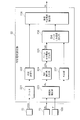
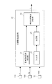
- FIG. 1 is a diagram showing a schematic configuration of an electric power steering apparatus according to an embodiment. It is a schematic block diagram of a control device. It is a schematic block diagram of the addition current setting part concerning a 1st embodiment.
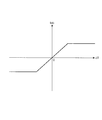
- FIG. 7 is a schematic view of a control map showing correspondence between relative steering angle and base addition current. It is a flowchart which shows the procedure of the target current setting process which a target current setting part performs. It is a figure which shows the relationship between a steering angle and steering torque. It is a figure which shows the relationship between steering torque and the moving amount
- FIG. 6 is a schematic view of a control map showing correspondence between relative steering torque and a base additional current. It is a schematic block diagram of the addition current setting part concerning a 3rd embodiment. It is a schematic block diagram of the addition current setting part concerning a 4th embodiment. It is a schematic block diagram of the target current setting part concerning a 5th embodiment.
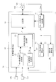
- FIG. 1 is a diagram showing a schematic configuration of an electric power steering apparatus 100 according to the embodiment.
- Electric power steering apparatus 100 (hereinafter sometimes referred to simply as “steering apparatus 100") is a steering apparatus for arbitrarily changing the traveling direction of the vehicle, and in the present embodiment, an automobile as an example of the vehicle. The configuration applied to 1 is illustrated.
- FIG. 1 is a view of the automobile 1 viewed from the front.
- the steering apparatus 100 includes a steering wheel (handle) 101 in the form of a wheel as an example of a steering member operated by a driver to change the traveling direction of the automobile 1 and a steering provided integrally with the steering wheel 101. And a shaft 102.
- the steering apparatus 100 also includes an upper connecting shaft 103 connected to the steering shaft 102 via a universal joint 103a, and a lower connecting shaft 108 connected to the upper connecting shaft 103 via a universal joint 103b. .
- the lower connecting shaft 108 rotates in conjunction with the rotation of the steering wheel 101.
- the steering device 100 also includes tie rods 104 connected to the left and right wheels 150 as rolling wheels, and a rack shaft 105 connected to the tie rods 104.
- the steering device 100 also includes a pinion 106 a that constitutes a rack and pinion mechanism together with rack teeth 105 a formed on the rack shaft 105.
- the pinion 106 a is formed at the lower end of the pinion shaft 106.
- the pinion shaft 106 applies a driving force (rack axial force) to roll the left and right wheels 150 by rotating with respect to the rack shaft 105.
- the steering device 100 also has a steering gear box 107 that houses the pinion shaft 106.
- the pinion shaft 106 is connected to the lower connecting shaft 108 via a torsion bar 112 in the steering gear box 107.
- a steering torque T applied to the steering wheel 101 based on the relative rotational angle between the lower connecting shaft 108 and the pinion shaft 106, in other words, based on the amount of torsion of the torsion bar 112.
- a torque sensor 109 is provided as an example of a torque detection unit that detects the torque.
- the steering apparatus 100 also includes an electric motor 110 supported by a steering gear box 107 and a reduction mechanism 111 that decelerates the driving force of the electric motor 110 and transmits it to the pinion shaft 106.
- the reduction mechanism 111 has a worm wheel 111a fixed to the pinion shaft 106, and a worm 111b connected to the output shaft of the electric motor 110 via a shaft coupling (not shown).
- the electric motor 110 applies a driving force (rack axial force) for rolling the wheel 150 to the rack shaft 105 by applying a rotational driving force to the pinion shaft 106.
- the electric motor 110 according to the present embodiment is a three-phase brushless motor having a resolver 120 that outputs a rotation angle signal ⁇ ms interlocked with a motor rotation angle ⁇ m that is a rotation angle of the electric motor 110.
- the steering device 100 also includes a control device 10 that controls the operation of the electric motor 110.
- the control device 10 receives an output signal from the torque sensor 109 described above.
- the control device 10 is a vehicle speed sensor that detects a vehicle speed Vc, which is a moving speed of the vehicle 1, via a network (CAN) that performs communication to flow signals for controlling various devices mounted on the vehicle 1.
- An output signal v from 170 is input.
- the steering apparatus 100 configured as described above drives the electric motor 110 based on the steering torque T detected by the torque sensor 109, and transmits the driving force (generated torque) of the electric motor 110 to the pinion shaft 106.
- the driving force (generated torque) of the electric motor 110 assists the driver's steering applied to the steering wheel 101.
- the electric motor 110 applies an assist force (assisting force) to the steering of the steering wheel 101 by the driver.
- FIG. 2 is a schematic configuration diagram of the control device 10.
- the control device 10 is an arithmetic logic operation circuit including a CPU, a ROM, a RAM, a backup RAM, and the like.
- a torque signal Td obtained by converting the steering torque T detected by the torque sensor 109 described above into an output signal, a vehicle speed signal v corresponding to the vehicle speed Vc from the vehicle speed sensor 170, and a rotation angle from the resolver 120 A signal ⁇ ms or the like is input.
- control device 10 calculates a target current It necessary for the electric motor 110 to supply based on the torque signal Td, the vehicle speed signal v, and the like, and the target current setting unit 20. And a controller 30 for performing feedback control and the like based on the target current It calculated.
- Control device 10 calculates motor rotation speed Vm based on motor rotation angle ⁇ m calculated by motor rotation angle calculation unit 71 that calculates motor rotation angle ⁇ m of electric motor 110, and motor rotation angle calculation unit 71.
- a motor rotation speed calculation unit 72 that calculates the rotation speed.
- the control device 10 includes a steering angle calculation unit 73 that calculates a steering angle ⁇ s that is a rotation angle of the steering wheel 101.
- the target current setting unit 20 calculates a basic target current Ib that is a basis for setting the target current It, and an additional current Ia to be added to the basic target current Ib in a predetermined case described later. And an additional current setting unit 22 for setting. Further, the target current setting unit 20 includes a final target current setting unit 23 that determines a target current It to be finally supplied to the electric motor 110.
- the basic target current setting unit 21 sets a basic target current Ib based on the torque signal Td and the vehicle speed signal v.
- the basic target current setting unit 21 can exemplify that the basic target current Ib is positive when the steering torque T is positive, and is negative when the steering torque T is negative. . Further, when the absolute values of the steering torque T are the same, the basic target current setting unit 21 can exemplify increasing the absolute value of the basic target current Ib as the vehicle speed Vc is lower.
- the basic target current setting unit 21 may set a dead zone where the basic target current Ib is 0 regardless of the value of the steering torque T. That the basic target current setting unit 21 sets the basic target current Ib means, in other words, the basic target current setting unit 21 sets the basic driving force based on the steering torque T.
- the additional current setting unit 22 will be described in detail later.
- Control unit 30 detects a motor drive control unit (not shown) for controlling the operation of electric motor 110, a motor drive unit (not shown) for driving electric motor 110, and an actual current Im actually flowing in electric motor 110. And a motor current detection unit (not shown).
- the motor drive control unit performs feedback based on the deviation between the target current It finally determined by the target current setting unit 20 and the actual current Im supplied to the electric motor 110 detected by the motor current detection unit. It has a feedback (F / B) control part (not shown) which performs control.
- the motor drive control unit also has a PWM signal generation unit (not shown) that generates a PWM (pulse width modulation) signal for PWM driving the electric motor 110.
- the motor drive unit is a so-called inverter, and includes, for example, six independent transistors (FETs) as switching elements, and three of the six transistors are connected between the positive side line of the power supply and the electric coil of each phase. The other three transistors are connected between the electrical coil of each phase and the negative side (ground) line of the power supply. Then, the drive of the electric motor 110 is controlled by driving the gates of two transistors selected from among the six transistors and performing a switching operation of these transistors.
- the motor current detection unit detects the value of the actual current Im flowing to the electric motor 110 from the voltage generated at both ends of the shunt resistor connected to the motor drive unit.
- the motor rotation angle calculation unit 71 calculates the motor rotation angle ⁇ m based on the rotation angle signal ⁇ ms from the resolver 120.
- the motor rotation speed calculation unit 72 calculates the motor rotation speed Vm of the electric motor 110 based on the motor rotation angle ⁇ m calculated by the motor rotation angle calculation unit 71.
- the steering angle calculation unit 73 has a correlation between the rotation angle (steering angle ⁇ s) of the steering wheel 101 and the motor rotation angle ⁇ m of the electric motor 110 because the steering wheel 101, the reduction mechanism 111, etc. are mechanically connected.
- the steering angle ⁇ s is calculated based on the motor rotation angle ⁇ m calculated by the motor rotation angle calculation unit 71.
- the steering angle calculation unit 73 performs steering based on the integrated value of the difference between the previous value and the current value of the motor rotation angle ⁇ m calculated periodically (for example, every one millisecond) by the motor rotation angle calculation unit 71. Calculate the angle ⁇ s.
- the direction in which the relative rotation angle occurs is positive (steering torque T is positive).
- the direction in which the relative rotational angle between the steering wheel 101 (lower connecting shaft 108) and the pinion shaft 106 changes (the direction in which the relative rotational angle occurs) at the time of left rotation of the steering wheel 101 from the neutral state Is negative).
- the basic target current setting portion 21 calculates the basic target current Ib so as to rotate the electric motor 110 in the clockwise direction, and the basic target current Ib is calculated.
- the direction in which the target current Ib flows is positive. That is, when the steering torque T is plus, the basic target current setting unit 21 calculates the plus basic target current Ib, and generates torque in the direction of rotating the electric motor 110 in the right rotation direction.
- the basic target current setting unit 21 calculates the negative basic target current Ib, and generates torque in the direction of rotating the electric motor 110 in the left rotation direction.
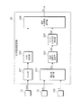
- FIG. 3 is a schematic configuration diagram of the additional current setting unit 22 according to the first embodiment.
- the additional current setting unit 22 is a filter 221 that filters the motor rotational speed signal Vms from the motor rotational speed calculation unit 72, and an additional determination unit that determines whether to add the additional current Ia based on the output from the filter 221 And 222 are provided.
- the additional current setting unit 22 corrects the steering angle ⁇ s to calculate the corrected steering angle ⁇ c, and the corrected steering angle ⁇ c is calculated based on the corrected steering angle ⁇ c.
- a relative steering angle calculation unit 224 is provided which calculates the relative steering angle ⁇ c of the previous value ⁇ c (n ⁇ 1) of the steering angle ⁇ c and the current value ⁇ c (n).
- the additional current setting unit 22 includes a base additional current calculation unit 225 that calculates a base additional current Iab serving as a base of the additional current Ia based on the relative steering angle ⁇ c calculated by the relative steering angle calculation unit 224. Further, the additional current setting unit 22 sets a final additional current Ia based on the determination made by the additional determination unit 222 and the base additional current Iab calculated by the base additional current calculation unit 225. It has 226.
- the filter 221 has a function of removing a frequency band component higher than a predetermined frequency to extract only a low frequency band component lower than a predetermined frequency, and a function of removing a predetermined frequency band component in a frequency band lower than the predetermined frequency. Filter.
- the addition determination unit 222 determines to supply the additional current Ia when the motor rotation speed Vm calculated by the motor rotation speed calculation unit 72 is 0 based on the output value from the filter 221, and the motor rotation speed calculation unit When the motor rotational speed Vm calculated by 72 is not 0, it is not determined to supply the additional current Ia.
- the addition determination unit 222 determines, based on the motor rotation speed Vm of the electric motor 110, an example of a determination unit that determines whether to set a driving force larger than the basic driving force caused by the basic target current Ib. Function.
- the steering angle correction unit 223 calculates the post-correction steering angle ⁇ c based on the steering angle ⁇ s calculated by the steering angle calculation unit 73 and the steering torque T detected by the torque sensor 109.
- the correction steering angle ⁇ t is a steering angle ⁇ s for which the driver steers the steering wheel 101 but the torsion bar 112 is twisted and the rotation of the pinion shaft 106 is not achieved.
- the steering angle correction unit 223 calculates the correction steering angle ⁇ t by multiplying the steering torque T detected by the torque sensor 109 by a predetermined coefficient (for example, the reciprocal of the spring rate of the torsion bar 112).
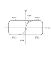
- FIG. 4 is a schematic view of a control map showing the correspondence between the relative steering angle ⁇ c and the base additional current Iab.
- the base additional current calculation unit 225 calculates a base additional current Iab according to the relative steering angle ⁇ c calculated by the relative steering angle calculation unit 224.
- the base additional current calculation unit 225 is, for example, relative to the control map illustrated in FIG. 4 showing the correspondence between the relative steering angle ⁇ c and the base additional current Iab, which is created in advance based on a rule of thumb and stored in the ROM.
- the base additional current Iab is calculated by substituting the steering angle ⁇ c. That the base addition current calculation unit 225 calculates the base addition current Iab means, in other words, the addition drive to be added to the basic driving force caused by the basic target current Ib based on the steering angle ⁇ s. It is to set the power.
- the base additional current Iab is positive. If the steering torque T is positive and the basic target current Ib is positive when it is cut in the right rotation direction, the base additional current Iab has the same sign as the basic target current Ib. On the other hand, when the steering wheel 101 is cut in the left rotation direction, the base added current Iab becomes negative. If the steering torque T is negative and the basic target current Ib is negative when it is cut in the left rotation direction, the base additional current Iab has the same sign as the basic target current Ib.
- the final addition current setting unit 226 sets the base addition current Iab calculated by the base addition current calculation unit 225 as the addition current Ia, and the addition determination unit 222 If it is not decided to supply the additional current Ia, 0 is set as the additional current Ia.
- FIG. 5 is a flowchart showing the procedure of the target current setting process performed by the target current setting unit 20.
- the target current setting unit 20 repeatedly executes this target current setting process, for example, every predetermined period (for example, one millisecond).
- the target current setting unit 20 sets a basic target current Ib (S501). This is processing in which the basic target current setting unit 21 calculates the basic target current Ib as described above.
- the target current setting unit 20 calculates the corrected steering angle ⁇ c (S502). This is processing that the steering angle correction unit 223 calculates based on the steering angle ⁇ s calculated by the steering angle calculation unit 73 and the steering torque T detected by the torque sensor 109.
- the target current setting unit 20 calculates the relative steering angle ⁇ c (S503). This is because the relative steering angle calculation unit 224 calculates the previous value ⁇ c (n ⁇ ) of the corrected steering angle ⁇ c calculated in S502 of the previous flow from the current value ⁇ c (n) of the corrected steering angle ⁇ c calculated in S502. 1) is a process of subtracting. Thereafter, the target current setting unit 20 calculates the base additional current Iab (S504). This is processing that the base additional current calculation unit 225 calculates based on the relative steering angle ⁇ c calculated in S503.
- the target current setting unit 20 determines whether to add the additional current Ia (S505). This is because the addition determination unit 222 determines to add (supply) the additional current Ia when the acquired motor rotational speed Vm is 0, and adds the additional current Ia when the motor rotational speed Vm is not 0. It is a process to decide not to (supply).
- the target current setting unit 20 sets the base additional current Iab calculated in S504 as the additional current Ia (S506). On the other hand, when it is determined not to supply (No in S505), the target current setting unit 20 sets the additional current Ia to 0 (S507).
- the target current setting unit 20 sets the target current It (S508).
- the electric motor 110 that applies an assisting force to the steering wheel 101, the torque sensor 109 that detects the steering torque T, and the torque sensor 109 detect Based on the basic target current setting unit 21 that sets the basic driving force of the electric motor 110 based on the steering torque T, and based on the motor rotation speed Vm of the electric motor 110, whether the driving force is larger than the basic driving force It is an example of a steering control apparatus provided with the addition determination part 222 as an example of the determination part to determine. Then, when the motor rotation speed Vm is 0, the addition determination unit 222 determines to set a driving force larger than the basic driving force.
- the steering apparatus 100 can rotate the electric motor 110 with the basic driving force of the electric motor 110 based on the steering torque T detected by the electric motor 110, the torque sensor 109, and the torque sensor 109.
- the controller 10 is provided with a driving force that is larger than the basic driving force (when the motor rotational speed Vm is 0).
- to make the driving force larger than the basic driving force means adding a driving force in the same rotational direction as the basic driving force to the rotational direction of the electric motor 110 to the basic driving force.
- the basic target current Ib which is the basis of the basic driving force is positive
- a value obtained by adding the positive additional current Ia to the basic target current Ib is taken as the target current It.
- the basic target current Ib that is the basis of the basic driving force is negative, a value obtained by adding the negative additional current Ia to the basic target current Ib is taken as the target current It.
- the steering device 100 sets a steering angle correction unit 223 as an example of an additional driving force setting unit that sets an additional driving force to be added to the basic driving force based on the steering angle ⁇ s of the steering wheel 101. And a relative steering angle calculation unit 224 and a base additional current calculation unit 225.
- the steering apparatus 100 according to the first embodiment sets a final target current as an example of a final driving force setting unit that sets a driving force larger than the basic driving force by adding an additional driving force to the basic driving force.
- the unit 23 is provided.
- FIG. 6 is a diagram showing the relationship between the steering angle ⁇ s and the steering torque T.
- FIG. 7 is a diagram showing the relationship between the steering torque T and the movement amount of the rack shaft 105.
- the relationship between the steering apparatus 100 according to the present embodiment is shown by a solid line, and a configuration different from the steering apparatus 100 according to the present embodiment in that the additional current Ia is not added to the target current It is compared. As an example, it is indicated by a broken line.
- FIG. 6 shows a case where the steering wheel 101 is cut in the right direction from the state where the steering angle ⁇ s is zero.
- the additional current Ia is not added.
- the rack shaft 105 moves earlier, for example, at the start of cutting of the steering wheel 101 than in the comparative example, and the wheels 150 are rolled.
- the output shaft of the electric motor 110 The driving force resulting from the additional current Ia is added even when the pinion shaft 106 does not rotate without overcoming the frictional force between the worm 111b fixed to the motor and the worm wheel 111a fixed to the pinion shaft 106. Thus, the pinion shaft 106 is rotated. Therefore, for example, the time until the application of the assist force by the electric motor 110 is started at the start of cutting of the steering wheel 101 becomes short. Therefore, according to the steering apparatus 100 according to the first embodiment, as shown in FIG. 6 and FIG.
- the assist force by the electric motor 110 is applied from the beginning of the start of the steering wheel 101 cut to reduce the steering load.
- the steering torque T becomes smaller when the steering angle ⁇ s is small), and the rack shaft 105 starts moving early.
- the steering angle ⁇ s does not easily increase even if the steering torque T is increased at the beginning of the start of the turning of the steering wheel 101 (rack shaft 105 hardly moves)
- the steering angle ⁇ s increases as the steering torque T increases, so that the steering feeling improves.
- the addition determination unit 222 determines to supply the additional current Ia when the motor rotation speed Vm is 0, and adds the additional current Ia when the motor rotation speed Vm is not 0. Although it does not determine to supply, it is not limited in particular to the aspect which concerns. For example, addition determination unit 222 determines to supply additional current Ia when the absolute value of motor rotation speed Vm is equal to or less than a predetermined rotation speed, and the absolute value of motor rotation speed Vm is greater than the predetermined rotation speed. In this case, it may not be decided to supply the additional current Ia.
- the motor rotational speed Vm when the absolute value of the motor rotational speed Vm is equal to or less than the predetermined rotational speed, the motor rotational speed Vm may be regarded as 0 (the absolute value of the motor rotational speed Vm is equal to or less than the predetermined rotational speed)
- the area may be a dead zone area).
- the addition determination unit 222 may further determine with reference to the steering angular velocity V ⁇ and the steering angle ⁇ s when determining whether to supply the additional current Ia.
- the addition determination unit 222 can illustrate grasping of the steering angular velocity V ⁇ based on the steering angle ⁇ s calculated by the steering angle calculation unit 73. For example, even if the motor rotation speed Vm is 0 (or the absolute value of the motor rotation speed Vm is equal to or less than a predetermined rotation speed), the addition determination unit 222 determines that the absolute value of the steering angular velocity V ⁇ is equal to or less than the predetermined speed.
- the rack shaft 105 moves and the wheel 150 is moved even though the driver does not intentionally steer the steering wheel 101 when the steering angle ⁇ s is around 0 (the absolute value of the steering angle ⁇ s is equal to or less than a predetermined angle). Rolling is suppressed.
- the steering apparatus 100 according to the second embodiment differs from the steering apparatus 100 according to the first embodiment in the additional current setting unit 22 of the target current setting unit 20 of the control device 10.
- differences from the steering apparatus 100 according to the first embodiment will be described, and description of the same points as the steering apparatus 100 according to the first embodiment will be omitted.
- FIG. 8 is a schematic configuration diagram of the additional current setting unit 22 according to the second embodiment.
- the additional current setting unit 22 according to the second embodiment differs from the additional current setting unit 22 according to the first embodiment in the method of calculating the base additional current Iab.
- the additional current setting unit 22 according to the second embodiment calculates a base additional current Iab based on the steering torque T detected by the torque sensor 109.
- the additional current setting unit 22 determines the previous value T (n-1) of the steering torque T based on the steering torque T detected by the torque sensor 109. And a current steering torque .DELTA.T of a current value T (n), and a base additional current calculation unit 235 which calculates a base additional current Iab based on the relative steering torque .DELTA.T.
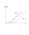
- FIG. 9 is a schematic view of a control map showing the correspondence between relative steering torque ⁇ T and base additional current Iab.
- the base additional current calculation unit 235 calculates a base additional current Iab according to the relative steering torque ⁇ T calculated by the relative steering torque calculation unit 234.
- the base additional current calculation unit 235 is, for example, relative to the control map illustrated in FIG. 9 showing the correspondence between the relative steering torque ⁇ T and the base additional current Iab, which is created in advance based on a rule of thumb and stored in the ROM. By substituting the steering torque ⁇ T, the base additional current Iab is calculated.
- the absolute value of the base additional current Iab increases as the absolute value of the relative steering torque ⁇ T increases.
- the base additional current Iab is set to be constant.
- the correlation between the relative steering torque ⁇ T and the base additional current Iab illustrated in FIG. 9 may be changed according to the vehicle speed Vc. For example, even if the relative steering torque ⁇ T is the same, the base additional current Iab may be set to increase as the vehicle speed Vc decreases.
- the steering apparatus 100 is a relative steering torque calculation unit as an example of an additional driving force setting unit that sets an additional driving force to be added to the basic driving force based on the steering torque T detected by the torque sensor 109. And 234 and a base additional current calculation unit 235.
- the target current It is set by adding the additional current Ia to the basic target current Ib.
- the time until the application of the assist force by the electric motor 110 is started when the operation such as time starts is shortened. Since the additional current Ia increases as the steering torque T increases, the steering load at the start of the operation of the steering wheel 101 can be reduced more accurately.
- the steering apparatus 100 according to the third embodiment differs from the steering apparatus 100 according to the first embodiment in the additional current setting unit 22 of the target current setting unit 20 of the control device 10.
- differences from the steering apparatus 100 according to the first embodiment will be described, and description of the same points as the steering apparatus 100 according to the first embodiment will be omitted.
- FIG. 10 is a schematic configuration diagram of the additional current setting unit 22 according to the third embodiment.
- the additional current setting unit 22 according to the third embodiment has a function of setting the base additional current Iab to 0 when a predetermined condition is satisfied with respect to the additional current setting unit 22 according to the first embodiment. It is different in having the point.
- the additional current setting unit 22 is performed by the determination unit 237 which determines whether a predetermined condition for setting the base additional current Iab to 0 is satisfied, and the determination unit 237.
- a final base additional current setting unit 238 that finally sets the base additional current Iab based on the determination and the base additional current Iab calculated by the base additional current calculation unit 225.
- the determination unit 237 determines that the predetermined condition is satisfied. If at least one of the absolute value of V ⁇ is greater than the predetermined speed or the absolute value of the steering angle ⁇ s is greater than the predetermined angle, it is determined that the predetermined condition is not satisfied.
- the determination unit 237 can exemplify grasping of the steering angular velocity V ⁇ based on the steering angle ⁇ s calculated by the steering angle calculation unit 73.
- the final base addition current setting unit 238 sets the base addition current Iab output to the final addition current setting unit 226 to zero.
- the base addition current calculation unit 225 outputs the base addition current Iab to be output to the final addition current setting unit 226. Is set to the calculated base addition current Iab.
- the steering device 100 sets a steering angle correction unit 223 as an example of an additional driving force setting unit that sets an additional driving force to be added to the basic driving force based on the steering angle ⁇ s of the steering wheel 101;
- a steering angle calculation unit 224, a base additional current calculation unit 225, a determination unit 237, and a final base additional current setting unit 238 are provided. Then, based on the steering angular velocity V ⁇ and the steering angle ⁇ s, the determination unit 237 determines whether to set the base additional current Iab, and hence the additional current Ia (additional driving force) to zero.
- the additional current Ia is zero. It becomes. Therefore, although the driver intentionally steers the steering wheel 101 when the steering angle ⁇ s is near 0 (the absolute value of the steering angle ⁇ s is equal to or less than a predetermined angle), the rack shaft 105 moves and the wheel 150 Rolling is suppressed.
- FIG. 11 is a schematic configuration diagram of the additional current setting unit 22 according to the fourth embodiment.
- the steering apparatus 100 according to the fourth embodiment includes a steering angle sensor 180 that detects a steering angle ⁇ s, as compared with the steering apparatus 100 according to the first embodiment, and a target current setting unit of the control device 10
- the twenty additional current setting units 22 are different.
- differences from the steering apparatus 100 according to the first embodiment will be described, and description of the same points as the steering apparatus 100 according to the first embodiment will be omitted.
- the steering angle sensor 180 can be exemplified to have the following structure.
- first rotating member attached to the steering shaft 102 itself and rotating in synchronization with the steering shaft 102
- second rotating member rotating in conjunction with the rotation of the first rotating member
- a magnetoresistive element for detecting a change in the magnetic field of the magnetized portion fixed to the second rotating member.
- the steering angle sensor 180 then outputs sine and cosine signals corresponding to the rotation angle of the steering wheel 101.
- the additional current setting unit 22 according to the fourth embodiment differs from the additional current setting unit 22 according to the first embodiment in the method of calculating the relative steering angle ⁇ c.
- the relative steering angle calculation unit 224 of the additional current setting unit 22 according to the fourth embodiment calculates the relative steering angle ⁇ c based on the detected steering angle ⁇ d detected by the steering angle sensor 180.
- the relative steering angle calculation unit 224 subtracts the previous value ⁇ d (n-1) from the current value ⁇ d (n) of the detected steering angle ⁇ d detected by the steering angle sensor 180.
- the steering apparatus 100 sets a relative steering angle calculation unit 224 as an example of an additional driving force setting unit that sets an additional driving force to be added to the basic driving force based on the steering angle ⁇ s of the steering wheel 101
- a base additional current calculation unit 225 is provided.
- the relative steering angle calculation unit 224 sets the base additional current Iab and hence the additional current Ia (additional driving force) based on the detected steering angle ⁇ d detected by the steering angle sensor 180 that detects the steering angle ⁇ s.
- the relative steering angle ⁇ c is calculated based on the detected steering angle ⁇ d detected by the steering angle sensor 180 that detects the steering angle ⁇ s, and the relative steering angle ⁇ c is calculated. Since the base additional current Iab is calculated on the basis of this, the additional current Ia that matches the driver's operation of the steering wheel 101 can be made more accurately.
- FIG. 12 is a schematic configuration diagram of the target current setting unit 20 according to the fifth embodiment.
- the target current setting unit 20 is different from the steering apparatus 100 according to the first embodiment.
- differences from the steering apparatus 100 according to the first embodiment will be described, and description of the same points as the steering apparatus 100 according to the first embodiment will be omitted.
- the target current setting unit 20 according to the fifth embodiment is a basic target current setting unit 21 that sets a basic target current setting unit 21, a filter 24, and a target current It that is ultimately supplied to the electric motor 110. And a determination unit 25 that determines whether to set the target current Ib.
- the target current setting unit 20 according to the fifth embodiment includes a final target current determination unit 26 that determines a target current It to be finally supplied to the electric motor 110 based on the determination made by the determination unit 25.
- the filter 24 has the same function as the filter 221 according to the first embodiment.
- the determination unit 25 determines to supply the basic target current Ib when the motor rotation speed Vm calculated by the motor rotation speed calculation unit 72 is not 0 based on the output value from the filter 24. On the other hand, when the motor rotation speed Vm calculated by the motor rotation speed calculation unit 72 is 0, the determination unit 25 determines to supply a current different from the basic target current Ib based on the output value from the filter 24. .
- the determination unit 25 functions as an example of a determination unit that determines whether to set a driving force larger than the basic driving force caused by the basic target current Ib based on the motor rotational speed Vm of the electric motor 110. Do.
- determination unit 25 determines to supply a current different from basic target current Ib, and the absolute value of motor rotational speed Vm is If it is higher than the predetermined rotation speed, it may be determined to supply the basic target current Ib.
- the final target current determining unit 26 determines the target current It to be finally supplied to the electric motor 110 as the basic target current Ib.
- the final target current determination unit 26 determines that the determination unit 25 supplies a current different from the basic target current Ib
- the final target current It to be supplied to the electric motor 110 is calculated from the basic target current Ib. Also determined to large large current Ig.
- the final target current determination unit 26 can exemplify calculating the large current Ig as in the following (1) or (2).
- the final target current determination unit 26 calculates a large current Ig based on the torque signal Td and the vehicle speed signal v.
- the final target current determination unit 26 makes the large current Ig positive if the steering torque T is positive, and makes the large current Ig negative if the steering torque T is negative. Further, when the absolute value of the steering torque T is the same, the final target current determination unit 26 increases the absolute value of the large current Ig as the vehicle speed Vc decreases. Further, when the absolute value of the steering torque T is the same, the final target current determination unit 26 makes the absolute value of the large current Ig larger than the absolute value of the basic target current Ib.
- control device 10 has the basic control map for calculating the basic target current Ib and the large current control map for calculating the large current Ig, and it is determined that the determination unit 25 supplies the basic target current Ib Depending on whether or not it is possible to switch the control map for calculating the current which finally becomes the target current It.
- the large current control map uses the large current control map rather than the absolute value of the basic target current Ib calculated using the basic control map even if the absolute value of the steering torque T and the vehicle speed Vc are the same. The absolute value of the calculated large current Ig is made larger.
- the control map for large current is used rather than the driving force of the electric motor 110 due to the basic target current Ib calculated using the basic control map.
- the driving force due to the large current Ig calculated is calculated to be larger.
- the target current setting unit 20 according to the fifth embodiment determines that the determination unit 25 finally supplies the basic target current Ib, the control for basic operation is performed. If the basic target current Ib calculated using the map is determined, and the determination unit 25 determines to supply a current different from the basic target current Ib, the large current Ig calculated using the large current control map is determined. Good.
- a large current Ig larger than the basic target current Ib is determined as the target current It. Therefore, for example, the time until the application of the assist force by the electric motor 110 is started at the start of the operation such as when the steering wheel 101 starts to cut becomes short.
- the component of the control apparatus 10 in each embodiment mentioned above may be implement
- the software (computer program) can be provided as stored in a computer readable recording medium.
- the “computer-readable recording medium” is not limited to portable recording mediums such as flexible disks and CD-ROMs, but internal storage devices in computers such as various RAMs and ROMs, and external storage devices such as hard disks Also includes.
Landscapes
- Engineering & Computer Science (AREA)
- Chemical & Material Sciences (AREA)
- Combustion & Propulsion (AREA)
- Transportation (AREA)
- Mechanical Engineering (AREA)
- Power Engineering (AREA)
- Steering Control In Accordance With Driving Conditions (AREA)
- Power Steering Mechanism (AREA)
- Control Of Electric Motors In General (AREA)
Abstract
操舵制御装置は、ステアリングホイールの操舵に対する補助力を加える電動モータと、ステアリングホイールの操舵トルクを検出するトルクセンサ109と、トルクセンサ109が検出した操舵トルクに基づいて電動モータの基本駆動力を設定する基本目標電流設定部と、電動モータの回転速度に基づいて、基本駆動力よりも大きい駆動力とするか否かを決定する付加決定部222と、を備える。
Description
本発明は、操舵制御装置、電動パワーステアリング装置に関する。
従来、電動パワーステアリング装置は、摩擦要素を有していることが知られている。例えば、特許文献1に記載の電動パワーステアリング装置は、電動モータの回転軸に取着したギアと、このギアと噛合されハンドル軸に固定されたギアとから構成された減速機を有している。そして、特許文献1に記載の電動パワーステアリング装置においては、車速と操舵トルクより目標電流を生成してアシスト力を発生させるようにモータ制御を行っている。
電動パワーステアリング装置などの操舵制御装置は摩擦要素を有していることから、操舵トルクに基づいて生成した目標電流に起因する電動モータの駆動力では摩擦力に打ち勝てず、ラックが移動しない(タイヤが転動しない)おそれがある。それゆえ、例えばステアリングホイール(操舵部材)の切り込み開始時に、切り込み開始から電動モータによるアシスト力が付与開始されるまでに時間差が生じるおそれがある。
本発明は、操舵部材の操作開始時に電動モータによるアシスト力が付与開始されるまでの時間を短くすることができる電動パワーステアリング装置を提供することを目的とする。
本発明は、操舵部材の操作開始時に電動モータによるアシスト力が付与開始されるまでの時間を短くすることができる電動パワーステアリング装置を提供することを目的とする。
かかる目的のもと、本発明は、操舵部材の操舵に対する補助力を加える電動モータと、前記操舵部材の操舵トルクを検出するトルク検出部と、前記トルク検出部が検出した前記操舵トルクに基づいて前記電動モータの基本駆動力を設定する基本駆動力設定部と、前記電動モータの回転速度に基づいて、前記基本駆動力よりも大きい駆動力とするか否かを決定する決定部と、を備える操舵制御装置である。
本発明によれば、操舵部材の操作開始時に電動モータによるアシスト力が付与開始されるまでの時間を短くすることができる。
以下、添付図面を参照して、本発明の実施の形態について詳細に説明する。
<第1の実施形態>
図1は、実施の形態に係る電動パワーステアリング装置100の概略構成を示す図である。
電動パワーステアリング装置100(以下、単に「ステアリング装置100」と称する場合もある。)は、車両の進行方向を任意に変えるためのかじ取り装置であり、本実施の形態においては車両の一例としての自動車1に適用した構成を例示している。なお、図1は、自動車1を前方から見た図である。
<第1の実施形態>
図1は、実施の形態に係る電動パワーステアリング装置100の概略構成を示す図である。
電動パワーステアリング装置100(以下、単に「ステアリング装置100」と称する場合もある。)は、車両の進行方向を任意に変えるためのかじ取り装置であり、本実施の形態においては車両の一例としての自動車1に適用した構成を例示している。なお、図1は、自動車1を前方から見た図である。
ステアリング装置100は、自動車1の進行方向を変えるために運転者が操作する操舵部材の一例としての車輪(ホイール)状のステアリングホイール(ハンドル)101と、ステアリングホイール101に一体的に設けられたステアリングシャフト102とを備えている。また、ステアリング装置100は、ステアリングシャフト102と自在継手103aを介して連結された上部連結シャフト103と、この上部連結シャフト103と自在継手103bを介して連結された下部連結シャフト108とを備えている。下部連結シャフト108は、ステアリングホイール101の回転に連動して回転する。
また、ステアリング装置100は、転動輪としての左右の車輪150それぞれに連結されたタイロッド104と、タイロッド104に連結されたラック軸105とを備えている。また、ステアリング装置100は、ラック軸105に形成されたラック歯105aとともにラック・ピニオン機構を構成するピニオン106aを備えている。ピニオン106aは、ピニオンシャフト106の下端部に形成されている。ピニオンシャフト106は、ラック軸105に対して、回転することにより左右の車輪150を転動させる駆動力(ラック軸力)を加える。
また、ステアリング装置100は、ピニオンシャフト106を収納するステアリングギヤボックス107を有している。ピニオンシャフト106は、ステアリングギヤボックス107内にてトーションバー112を介して下部連結シャフト108と連結されている。そして、ステアリングギヤボックス107の内部には、下部連結シャフト108とピニオンシャフト106との相対回転角度に基づいて、言い換えればトーションバー112の捩れ量に基づいて、ステアリングホイール101に加えられた操舵トルクTを検出するトルク検出部の一例としてのトルクセンサ109が設けられている。
また、ステアリング装置100は、ステアリングギヤボックス107に支持された電動モータ110と、電動モータ110の駆動力を減速してピニオンシャフト106に伝達する減速機構111とを有している。減速機構111は、ピニオンシャフト106に固定されたウォームホイール111aと、軸継手(不図示)を介して電動モータ110の出力軸に連結されるウォーム111bとを有する。電動モータ110は、ピニオンシャフト106に回転駆動力を加えることにより、ラック軸105に車輪150を転動させる駆動力(ラック軸力)を加える。本実施の形態に係る電動モータ110は、電動モータ110の回転角度であるモータ回転角度θmに連動した回転角度信号θmsを出力するレゾルバ120を有する3相ブラシレスモータである。
また、ステアリング装置100は、電動モータ110の作動を制御する制御装置10を備えている。制御装置10には、上述したトルクセンサ109からの出力信号が入力される。また、制御装置10には、自動車1に搭載される各種の機器を制御するための信号を流す通信を行うネットワーク(CAN)を介して、自動車1の移動速度である車速Vcを検出する車速センサ170からの出力信号vなどが入力される。
以上のように構成されたステアリング装置100は、トルクセンサ109が検出した操舵トルクTに基づいて電動モータ110を駆動し、電動モータ110の駆動力(発生トルク)をピニオンシャフト106に伝達する。これにより、電動モータ110の駆動力(発生トルク)が、ステアリングホイール101に加える運転者の操舵をアシストする。このように、電動モータ110は、運転者のステアリングホイール101の操舵に対してアシスト力(補助力)を付与する。
(制御装置)
次に、制御装置10について説明する。
図2は、制御装置10の概略構成図である。
制御装置10は、CPU、ROM、RAM、バックアップRAM等からなる算術論理演算回路である。
制御装置10には、上述したトルクセンサ109にて検出された操舵トルクTが出力信号に変換されたトルク信号Td、車速センサ170からの車速Vcに対応する車速信号v、レゾルバ120からの回転角度信号θmsなどが入力される。
次に、制御装置10について説明する。
図2は、制御装置10の概略構成図である。
制御装置10は、CPU、ROM、RAM、バックアップRAM等からなる算術論理演算回路である。
制御装置10には、上述したトルクセンサ109にて検出された操舵トルクTが出力信号に変換されたトルク信号Td、車速センサ170からの車速Vcに対応する車速信号v、レゾルバ120からの回転角度信号θmsなどが入力される。
そして、制御装置10は、トルク信号Td、車速信号vなどに基づいて電動モータ110が供給するのに必要となる目標電流Itを算出(設定)する目標電流設定部20と、目標電流設定部20が算出した目標電流Itに基づいてフィードバック制御などを行う制御部30とを備えている。また、制御装置10は、電動モータ110のモータ回転角度θmを算出するモータ回転角度算出部71と、モータ回転角度算出部71にて算出されたモータ回転角度θmに基づいて、モータ回転速度Vmを算出するモータ回転速度算出部72とを備えている。また、制御装置10は、ステアリングホイール101の回転角度である操舵角θsを算出する操舵角算出部73を備えている。
〔目標電流設定部〕
目標電流設定部20は、目標電流Itを設定する上で基本となる基本目標電流Ibを算出する基本目標電流設定部21と、後述する所定の場合に基本目標電流Ibに付加する付加電流Iaを設定する付加電流設定部22とを備えている。また、目標電流設定部20は、最終的に電動モータ110に供給する目標電流Itを決定する最終目標電流設定部23を備えている。
目標電流設定部20は、目標電流Itを設定する上で基本となる基本目標電流Ibを算出する基本目標電流設定部21と、後述する所定の場合に基本目標電流Ibに付加する付加電流Iaを設定する付加電流設定部22とを備えている。また、目標電流設定部20は、最終的に電動モータ110に供給する目標電流Itを決定する最終目標電流設定部23を備えている。
基本目標電流設定部21は、トルク信号Tdと、車速信号vとに基づいて基本目標電流Ibを設定する。基本目標電流設定部21は、操舵トルクTがプラスである場合には基本目標電流Ibはプラス、操舵トルクTがマイナスである場合には基本目標電流Ibはマイナスとすることを例示することができる。また、基本目標電流設定部21は、操舵トルクTの絶対値が同じである場合には、車速Vcが低速であるほど基本目標電流Ibの絶対値を大きくすることを例示することができる。なお、基本目標電流設定部21は、操舵トルクTの値に関わらず基本目標電流Ibを0とする不感帯領域を設定しても良い。基本目標電流設定部21が基本目標電流Ibを設定するということは、言い換えれば、基本目標電流設定部21は、操舵トルクTに基づいて基本駆動力を設定するということである。
付加電流設定部22については後で詳述する。
最終目標電流設定部23は、基本目標電流設定部21が設定した基本目標電流Ibと、付加電流設定部22が設定した付加電流Iaとを加算することにより得た値を目標電流Itに設定する(It=Ib+Ia)。
最終目標電流設定部23は、基本目標電流設定部21が設定した基本目標電流Ibと、付加電流設定部22が設定した付加電流Iaとを加算することにより得た値を目標電流Itに設定する(It=Ib+Ia)。
〔制御部〕
制御部30は、電動モータ110の作動を制御するモータ駆動制御部(不図示)と、電動モータ110を駆動させるモータ駆動部(不図示)と、電動モータ110に実際に流れる実電流Imを検出するモータ電流検出部(不図示)とを有している。
制御部30は、電動モータ110の作動を制御するモータ駆動制御部(不図示)と、電動モータ110を駆動させるモータ駆動部(不図示)と、電動モータ110に実際に流れる実電流Imを検出するモータ電流検出部(不図示)とを有している。
モータ駆動制御部は、目標電流設定部20にて最終的に決定された目標電流Itと、モータ電流検出部にて検出された電動モータ110へ供給される実電流Imとの偏差に基づいてフィードバック制御を行うフィードバック(F/B)制御部(不図示)を有している。また、モータ駆動制御部は、電動モータ110をPWM駆動するためのPWM(パルス幅変調)信号を生成するPWM信号生成部(不図示)を有している。
モータ駆動部は、所謂インバータであり、例えば、スイッチング素子として6個の独立したトランジスタ(FET)を備え、6個の内の3個のトランジスタは電源の正極側ラインと各相の電気コイルとの間に接続され、他の3個のトランジスタは各相の電気コイルと電源の負極側(アース)ラインと接続されている。そして、6個の中から選択した2個のトランジスタのゲートを駆動してこれらのトランジスタをスイッチング動作させることにより、電動モータ110の駆動を制御する。
モータ電流検出部は、モータ駆動部に接続されたシャント抵抗の両端に生じる電圧から電動モータ110に流れる実電流Imの値を検出する。
モータ電流検出部は、モータ駆動部に接続されたシャント抵抗の両端に生じる電圧から電動モータ110に流れる実電流Imの値を検出する。
〔モータ回転角度算出部、モータ回転速度算出部、操舵角算出部〕
モータ回転角度算出部71は、レゾルバ120からの回転角度信号θmsに基づいてモータ回転角度θmを算出する。
モータ回転速度算出部72は、モータ回転角度算出部71が算出したモータ回転角度θmに基づいて電動モータ110のモータ回転速度Vmを算出する。
モータ回転角度算出部71は、レゾルバ120からの回転角度信号θmsに基づいてモータ回転角度θmを算出する。
モータ回転速度算出部72は、モータ回転角度算出部71が算出したモータ回転角度θmに基づいて電動モータ110のモータ回転速度Vmを算出する。
操舵角算出部73は、ステアリングホイール101、減速機構111などが機械的に連結されているためにステアリングホイール101の回転角度(操舵角θs)と電動モータ110のモータ回転角度θmとの間に相関関係があることに鑑み、モータ回転角度算出部71にて算出されたモータ回転角度θmに基づいて操舵角θsを算出する。操舵角算出部73は、例えば、モータ回転角度算出部71にて定期的(例えば1ミリ秒毎)に算出されたモータ回転角度θmの前回値と今回値との差分の積算値に基づいて操舵角θsを算出する。
ここで、トーションバー112の捩れ量が0の状態(中立状態)からのステアリングホイール101の右回転時におけるステアリングホイール101(下部連結シャフト108)とピニオンシャフト106との相対回転角度が変化する方向(相対回転角度が生じる方向)をプラス(操舵トルクTがプラス)とする。また、中立状態からのステアリングホイール101の左回転時におけるステアリングホイール101(下部連結シャフト108)とピニオンシャフト106との相対回転角度が変化する方向(相対回転角度が生じる方向)をマイナス(操舵トルクTがマイナス)とする。
そして、トルクセンサ109にて検出された操舵トルクTがプラスであるときに、電動モータ110を右回転方向に回転させるように基本目標電流設定部21にて基本目標電流Ibが算出され、その基本目標電流Ibが流れる方向をプラスとする。つまり、操舵トルクTがプラスのときに基本目標電流設定部21はプラスの基本目標電流Ibを算出し、電動モータ110を右回転方向に回転させる方向のトルクを発生させる。操舵トルクTがマイナスのときに基本目標電流設定部21はマイナスの基本目標電流Ibを算出し、電動モータ110を左回転方向に回転させる方向のトルクを発生させる。
また、ステアリングホイール101の回転角度である操舵角θsが0度である状態からステアリングホイール101が右方向に回転した場合に操舵角θsがプラスとなり、左方向に回転した場合に操舵角θsがマイナスとなる。
また、ステアリングホイール101の回転角度である操舵角θsが0度である状態からステアリングホイール101が右方向に回転した場合に操舵角θsがプラスとなり、左方向に回転した場合に操舵角θsがマイナスとなる。
{付加電流設定部}
図3は、第1の実施形態に係る付加電流設定部22の概略構成図である。
付加電流設定部22は、モータ回転速度算出部72からのモータ回転速度信号Vmsをフィルタリングするフィルタ221と、フィルタ221からの出力に基づいて付加電流Iaを付加するか否かを決定する付加決定部222とを備えている。
また、付加電流設定部22は、操舵角θsを補正して補正後操舵角θcを算出する操舵角補正部223と、操舵角補正部223が算出した補正後操舵角θcに基づいて、補正後操舵角θcの前回値θc(n-1)と今回値θc(n)の相対操舵角Δθcを算出する相対操舵角算出部224とを備えている。
図3は、第1の実施形態に係る付加電流設定部22の概略構成図である。
付加電流設定部22は、モータ回転速度算出部72からのモータ回転速度信号Vmsをフィルタリングするフィルタ221と、フィルタ221からの出力に基づいて付加電流Iaを付加するか否かを決定する付加決定部222とを備えている。
また、付加電流設定部22は、操舵角θsを補正して補正後操舵角θcを算出する操舵角補正部223と、操舵角補正部223が算出した補正後操舵角θcに基づいて、補正後操舵角θcの前回値θc(n-1)と今回値θc(n)の相対操舵角Δθcを算出する相対操舵角算出部224とを備えている。
また、付加電流設定部22は、相対操舵角算出部224が算出した相対操舵角Δθcに基づいて付加電流Iaのベースとなるベース付加電流Iabを算出するベース付加電流算出部225を備えている。
また、付加電流設定部22は、付加決定部222が行った判定と、ベース付加電流算出部225が算出したベース付加電流Iabとに基づいて最終的に付加電流Iaを設定する最終付加電流設定部226を備えている。
また、付加電流設定部22は、付加決定部222が行った判定と、ベース付加電流算出部225が算出したベース付加電流Iabとに基づいて最終的に付加電流Iaを設定する最終付加電流設定部226を備えている。
フィルタ221は、所定の周波数より大きい周波数帯域成分を除去して所定の周波数以下の低周波数帯域成分だけを抽出する機能と、所定の周波数以下の周波数帯域内の所定周波数帯域成分を除去する機能とを備えるフィルタである。
付加決定部222は、フィルタ221からの出力値を基に、モータ回転速度算出部72が算出したモータ回転速度Vmが0である場合には付加電流Iaを供給すると決定し、モータ回転速度算出部72が算出したモータ回転速度Vmが0ではない場合には付加電流Iaを供給すると決定しない。このように、付加決定部222は、電動モータ110のモータ回転速度Vmに基づいて、基本目標電流Ibに起因する基本駆動力よりも大きい駆動力とするか否かを決定する決定部の一例として機能する。
操舵角補正部223は、操舵角算出部73が算出した操舵角θsと、トルクセンサ109が検出した操舵トルクTとに基づいて補正後操舵角θcを算出する。操舵角補正部223は、操舵角算出部73が算出した操舵角θsに、トルクセンサ109が検出した操舵トルクT相当分の補正用操舵角θtを加算することにより補正後操舵角θcを算出する(θc=θs+θt)。補正用操舵角θtは、運転者がステアリングホイール101を操舵しているがトーションバー112が捩れるだけでピニオンシャフト106の回転に至っていない分の操舵角θsである。操舵角補正部223は、トルクセンサ109が検出した操舵トルクTに予め定められた係数(例えばトーションバー112のバネレートの逆数)を乗算することにより、補正用操舵角θtを算出する。
相対操舵角算出部224は、補正後操舵角θcの今回値θc(n)から前回値θc(n-1)を減算することにより相対操舵角Δθcを算出する(Δθc=θc(n)-θc(n-1))。
図4は、相対操舵角Δθcとベース付加電流Iabとの対応を示す制御マップの概略図である。
ベース付加電流算出部225は、相対操舵角算出部224が算出した相対操舵角Δθcに応じたベース付加電流Iabを算出する。ベース付加電流算出部225は、例えば、予め経験則に基づいて作成しROMに記憶しておいた、相対操舵角Δθcとベース付加電流Iabとの対応を示す図4に例示した制御マップに、相対操舵角Δθcを代入することによりベース付加電流Iabを算出する。ベース付加電流算出部225がベース付加電流Iabを算出するということは、言い換えれば、ベース付加電流算出部225は、操舵角θsに基づいて、基本目標電流Ibに起因する基本駆動力に加える付加駆動力を設定するということである。
ベース付加電流算出部225は、相対操舵角算出部224が算出した相対操舵角Δθcに応じたベース付加電流Iabを算出する。ベース付加電流算出部225は、例えば、予め経験則に基づいて作成しROMに記憶しておいた、相対操舵角Δθcとベース付加電流Iabとの対応を示す図4に例示した制御マップに、相対操舵角Δθcを代入することによりベース付加電流Iabを算出する。ベース付加電流算出部225がベース付加電流Iabを算出するということは、言い換えれば、ベース付加電流算出部225は、操舵角θsに基づいて、基本目標電流Ibに起因する基本駆動力に加える付加駆動力を設定するということである。
なお、図4に例示した制御マップにおいては、ステアリングホイール101が右回転方向に切り込まれた場合には、ベース付加電流Iabはプラスとなる。右回転方向に切り込まれた場合には、操舵トルクTはプラスとなり、基本目標電流Ibはプラスとなることから、ベース付加電流Iabは、基本目標電流Ibの符号と同じ符合となる。他方、ステアリングホイール101が左回転方向に切り込まれた場合には、ベース付加電流Iabはマイナスとなる。左回転方向に切り込まれた場合には、操舵トルクTはマイナスとなり、基本目標電流Ibはマイナスとなることから、ベース付加電流Iabは、基本目標電流Ibの符号と同じ符合となる。
最終付加電流設定部226は、付加決定部222が付加電流Iaを供給すると決定した場合には、ベース付加電流算出部225が算出したベース付加電流Iabを付加電流Iaとして設定し、付加決定部222が付加電流Iaを供給すると決定していない場合には、付加電流Iaとして0を設定する。
次に、フローチャートを用いて、目標電流設定部20が行う目標電流設定処理の手順について説明する。
図5は、目標電流設定部20が行う目標電流設定処理の手順を示すフローチャートである。
目標電流設定部20は、この目標電流設定処理を、例えば予め定めた期間(例えば1ミリ秒)毎に繰り返し実行する。
図5は、目標電流設定部20が行う目標電流設定処理の手順を示すフローチャートである。
目標電流設定部20は、この目標電流設定処理を、例えば予め定めた期間(例えば1ミリ秒)毎に繰り返し実行する。
目標電流設定部20は、基本目標電流Ibを設定する(S501)。これは、基本目標電流設定部21が上述したようにして基本目標電流Ibを算出する処理である。
目標電流設定部20は、補正後操舵角θcを算出する(S502)。これは、操舵角補正部223が、操舵角算出部73が算出した操舵角θsと、トルクセンサ109が検出した操舵トルクTとに基づいて算出する処理である。
目標電流設定部20は、補正後操舵角θcを算出する(S502)。これは、操舵角補正部223が、操舵角算出部73が算出した操舵角θsと、トルクセンサ109が検出した操舵トルクTとに基づいて算出する処理である。
その後、目標電流設定部20は、相対操舵角Δθcを算出する(S503)。これは、相対操舵角算出部224が、S502にて算出した補正後操舵角θcの今回値θc(n)から前回のフローのS502にて算出した補正後操舵角θcの前回値θc(n-1)を減算する処理である。
その後、目標電流設定部20は、ベース付加電流Iabを算出する(S504)。これは、ベース付加電流算出部225が、S503にて算出した相対操舵角Δθcに基づいて算出する処理である。
その後、目標電流設定部20は、ベース付加電流Iabを算出する(S504)。これは、ベース付加電流算出部225が、S503にて算出した相対操舵角Δθcに基づいて算出する処理である。
その後、目標電流設定部20は、付加電流Iaを付加するか否かを判別する(S505)。これは、付加決定部222が、取得したモータ回転速度Vmが0である場合には付加電流Iaを付加(供給)すると決定し、モータ回転速度Vmが0ではない場合には付加電流Iaを付加(供給)しないと決定する処理である。
そして、供給すると決定した場合(S505でYes)、目標電流設定部20は、S504にて算出したベース付加電流Iabを付加電流Iaとして設定する(S506)。他方、供給しないと決定した場合(S505でNo)、目標電流設定部20は、付加電流Iaを0に設定する(S507)。
そして、目標電流設定部20は、目標電流Itを設定する(S508)。これは、最終目標電流設定部23が、S501にて設定した基本目標電流Ibと、S506又はS507にて設定した付加電流Iaとを加算することにより得た値を目標電流Itとして設定する処理である。
以上説明したように、第1の実施形態に係るステアリング装置100は、ステアリングホイール101の操舵に対する補助力を加える電動モータ110と、操舵トルクTを検出するトルクセンサ109と、トルクセンサ109が検出した操舵トルクTに基づいて電動モータ110の基本駆動力を設定する基本目標電流設定部21と、電動モータ110のモータ回転速度Vmに基づいて、基本駆動力よりも大きい駆動力とするか否かを決定する決定部の一例としての付加決定部222と、を備える操舵制御装置の一例である。そして、付加決定部222は、モータ回転速度Vmが0である場合には基本駆動力よりも大きい駆動力とすることを決定する。
言い換えると、第1の実施形態に係るステアリング装置100は、電動モータ110と、トルクセンサ109と、トルクセンサ109が検出した操舵トルクTに基づく電動モータ110の基本駆動力では電動モータ110が回転できていないときに(モータ回転速度Vmが0であるときに)、基本駆動力よりも大きい駆動力とする制御装置10とを備える。
ここで、基本駆動力よりも大きい駆動力とする、とは、基本駆動力に、基本駆動力の電動モータ110の回転方向と同じ回転方向の駆動力を付加することを意味する。言い換えると、基本駆動力の基となる基本目標電流Ibがプラスである場合には、基本目標電流Ibに、プラスの付加電流Iaを加算することにより得た値を目標電流Itとする。他方、基本駆動力の基となる基本目標電流Ibがマイナスである場合には、基本目標電流Ibに、マイナスの付加電流Iaを加算することにより得た値を目標電流Itとする。
ここで、基本駆動力よりも大きい駆動力とする、とは、基本駆動力に、基本駆動力の電動モータ110の回転方向と同じ回転方向の駆動力を付加することを意味する。言い換えると、基本駆動力の基となる基本目標電流Ibがプラスである場合には、基本目標電流Ibに、プラスの付加電流Iaを加算することにより得た値を目標電流Itとする。他方、基本駆動力の基となる基本目標電流Ibがマイナスである場合には、基本目標電流Ibに、マイナスの付加電流Iaを加算することにより得た値を目標電流Itとする。
また、第1の実施形態に係るステアリング装置100は、ステアリングホイール101の操舵角θsに基づいて基本駆動力に加える付加駆動力を設定する付加駆動力設定部の一例としての、操舵角補正部223、相対操舵角算出部224及びベース付加電流算出部225を備える。
また、第1の実施形態に係るステアリング装置100は、基本駆動力に付加駆動力を加えることで、基本駆動力よりも大きい駆動力を設定する最終駆動力設定部の一例としての最終目標電流設定部23を備える。
また、第1の実施形態に係るステアリング装置100は、基本駆動力に付加駆動力を加えることで、基本駆動力よりも大きい駆動力を設定する最終駆動力設定部の一例としての最終目標電流設定部23を備える。
《実施の形態に係るステアリング装置の作用、効果》
図6は、操舵角θsと操舵トルクTとの関係を示す図である。図7は、操舵トルクTとラック軸105の移動量との関係を示す図である。図6及び図7においては、本実施形態に係るステアリング装置100による関係を実線で示し、本実施形態に係るステアリング装置100に対して目標電流Itに付加電流Iaが加味されない点が異なる構成を比較例として破線で示している。また、図6では、操舵角θsが0である状態からステアリングホイール101が右方向に切り込まれた場合を示している。
図6は、操舵角θsと操舵トルクTとの関係を示す図である。図7は、操舵トルクTとラック軸105の移動量との関係を示す図である。図6及び図7においては、本実施形態に係るステアリング装置100による関係を実線で示し、本実施形態に係るステアリング装置100に対して目標電流Itに付加電流Iaが加味されない点が異なる構成を比較例として破線で示している。また、図6では、操舵角θsが0である状態からステアリングホイール101が右方向に切り込まれた場合を示している。
以上説明したように構成された第1の実施形態に係るステアリング装置100によれば、基本目標電流Ibに付加電流Iaが加算された目標電流Itに設定されるので、付加電流Iaが加算されない構成(比較例)よりも、例えばステアリングホイール101の切り込み開始時に早期にラック軸105が動き、車輪150が転動される。つまり、ステアリングホイール101が切り込まれてトルクセンサ109が操舵トルクTを検出していることにより設定される基本目標電流Ibに起因する駆動力(基本駆動力)では、例えば電動モータ110の出力軸に固定されたウォーム111bとピニオンシャフト106に固定されたウォームホイール111aとの間の摩擦力に打ち勝てずにピニオンシャフト106が回転しない場合においても、付加電流Iaに起因する駆動力が加算されることによりピニオンシャフト106が回転する。それゆえ、例えばステアリングホイール101の切り込み開始時に電動モータ110によるアシスト力が付与開始されるまでの時間が短くなる。従って、第1の実施形態に係るステアリング装置100によれば、図6、図7に示すように、例えばステアリングホイール101の切り込み開始初期から電動モータ110によるアシスト力が付与されて操舵負荷が軽減され(操舵角θsが小さいときから操舵トルクTが小さくなり)、早期にラック軸105が動き始める。また、図6、図7に示すように、比較例においては、ステアリングホイール101の切り込み開始初期に、操舵トルクTを大きくしても操舵角θsが大きくなり難い(ラック軸105が移動し難い)が、第1の実施形態に係るステアリング装置100によれば、操舵トルクTを大きくするのに応じて操舵角θsが大きくなるので、操舵フィーリングが向上する。
なお、上述した実施形態においては、付加決定部222が、モータ回転速度Vmが0である場合には付加電流Iaを供給すると決定し、モータ回転速度Vmが0ではない場合には付加電流Iaを供給すると決定しないが、特に係る態様に限定されない。例えば、付加決定部222は、モータ回転速度Vmの絶対値が予め定められた所定回転速度以下である場合に付加電流Iaを供給すると決定し、モータ回転速度Vmの絶対値が所定回転速度より大きい場合には付加電流Iaを供給すると決定しないようにしても良い。言い換えれば、モータ回転速度Vmの絶対値が所定回転速度以下である場合にはモータ回転速度Vmは0であるとみなすようにしても良い(モータ回転速度Vmの絶対値が所定回転速度以下である領域を不感帯領域としても良い)。
また、付加決定部222は、付加電流Iaを供給するか否かを決定する際に、モータ回転速度Vmに加えて、さらに操舵角速度Vθと操舵角θsとを参照して決定しても良い。付加決定部222は、操舵角算出部73が算出した操舵角θsに基づいて操舵角速度Vθを把握することを例示することができる。
例えば、付加決定部222は、モータ回転速度Vmが0(又はモータ回転速度Vmの絶対値が所定回転速度以下)である場合であっても、操舵角速度Vθの絶対値が所定速度以下であり、かつ、操舵角θsの絶対値が所定角以下である場合には、付加電流Iaを供給すると決定しないようにしても良い。これにより、操舵角θsが0付近(操舵角θsの絶対値が所定角以下)で、運転者が意図的にステアリングホイール101を操舵していないにもかかわらず、ラック軸105が動いて車輪150が転動することが抑制される。
例えば、付加決定部222は、モータ回転速度Vmが0(又はモータ回転速度Vmの絶対値が所定回転速度以下)である場合であっても、操舵角速度Vθの絶対値が所定速度以下であり、かつ、操舵角θsの絶対値が所定角以下である場合には、付加電流Iaを供給すると決定しないようにしても良い。これにより、操舵角θsが0付近(操舵角θsの絶対値が所定角以下)で、運転者が意図的にステアリングホイール101を操舵していないにもかかわらず、ラック軸105が動いて車輪150が転動することが抑制される。
<第2の実施形態>
第2の実施形態に係るステアリング装置100においては、第1の実施形態に係るステアリング装置100に対して、制御装置10の目標電流設定部20の付加電流設定部22が異なる。以下、第1の実施形態に係るステアリング装置100と異なる点について説明し、第1の実施形態に係るステアリング装置100と同じ点についての説明は省略する。
第2の実施形態に係るステアリング装置100においては、第1の実施形態に係るステアリング装置100に対して、制御装置10の目標電流設定部20の付加電流設定部22が異なる。以下、第1の実施形態に係るステアリング装置100と異なる点について説明し、第1の実施形態に係るステアリング装置100と同じ点についての説明は省略する。
図8は、第2の実施形態に係る付加電流設定部22の概略構成図である。
第2の実施形態に係る付加電流設定部22は、第1の実施形態に係る付加電流設定部22に対して、ベース付加電流Iabを算出する手法が異なる。第2の実施形態に係る付加電流設定部22は、トルクセンサ109が検出した操舵トルクTに基づいてベース付加電流Iabを算出する。
第2の実施形態に係る付加電流設定部22は、第1の実施形態に係る付加電流設定部22に対して、ベース付加電流Iabを算出する手法が異なる。第2の実施形態に係る付加電流設定部22は、トルクセンサ109が検出した操舵トルクTに基づいてベース付加電流Iabを算出する。
より具体的に、第2の実施形態に係る付加電流設定部22は、図8に示すように、トルクセンサ109が検出した操舵トルクTに基づいて、操舵トルクTの前回値T(n-1)と今回値T(n)の相対操舵トルクΔTを算出する相対操舵トルク算出部234と、相対操舵トルクΔTに基づいてベース付加電流Iabを算出するベース付加電流算出部235とを備えている。
相対操舵トルク算出部234は、トルクセンサ109が検出した操舵トルクTの今回値T(n)から前回値T(n-1)を減算することにより相対操舵トルクΔTを算出する(ΔT=T(n)-T(n-1))。
図9は、相対操舵トルクΔTとベース付加電流Iabとの対応を示す制御マップの概略図である。
ベース付加電流算出部235は、相対操舵トルク算出部234が算出した相対操舵トルクΔTに応じたベース付加電流Iabを算出する。ベース付加電流算出部235は、例えば、予め経験則に基づいて作成しROMに記憶しておいた、相対操舵トルクΔTとベース付加電流Iabとの対応を示す図9に例示した制御マップに、相対操舵トルクΔTを代入することによりベース付加電流Iabを算出する。なお、図9に例示した制御マップにおいては、相対操舵トルクΔTの絶対値が所定値以下である場合には相対操舵トルクΔTの絶対値が大きくなるに従ってベース付加電流Iabの絶対値が大きくなり、相対操舵トルクΔTの絶対値が所定値より大きい場合にはベース付加電流Iabが一定となるように設定されている。図9に例示した相対操舵トルクΔTとベース付加電流Iabとの相関関係を、車速Vcに応じて変更しても良い。例えば、相対操舵トルクΔTが同じであっても、車速Vcが小さいほどベース付加電流Iabが大きくなるように設定すると良い。
ベース付加電流算出部235は、相対操舵トルク算出部234が算出した相対操舵トルクΔTに応じたベース付加電流Iabを算出する。ベース付加電流算出部235は、例えば、予め経験則に基づいて作成しROMに記憶しておいた、相対操舵トルクΔTとベース付加電流Iabとの対応を示す図9に例示した制御マップに、相対操舵トルクΔTを代入することによりベース付加電流Iabを算出する。なお、図9に例示した制御マップにおいては、相対操舵トルクΔTの絶対値が所定値以下である場合には相対操舵トルクΔTの絶対値が大きくなるに従ってベース付加電流Iabの絶対値が大きくなり、相対操舵トルクΔTの絶対値が所定値より大きい場合にはベース付加電流Iabが一定となるように設定されている。図9に例示した相対操舵トルクΔTとベース付加電流Iabとの相関関係を、車速Vcに応じて変更しても良い。例えば、相対操舵トルクΔTが同じであっても、車速Vcが小さいほどベース付加電流Iabが大きくなるように設定すると良い。
第2の実施形態に係るステアリング装置100は、トルクセンサ109が検出した操舵トルクTに基づいて基本駆動力に加える付加駆動力を設定する付加駆動力設定部の一例としての、相対操舵トルク算出部234及びベース付加電流算出部235を備える。
以上説明したように構成された第2の実施形態に係るステアリング装置100によれば、基本目標電流Ibに付加電流Iaが加算された目標電流Itに設定されるので、例えばステアリングホイール101の切り込み開始時等の操作開始時に電動モータ110によるアシスト力が付与開始されるまでの時間が短くなる。そして、操舵トルクTが大きくなるほど付加電流Iaが大きくなるので、ステアリングホイール101の操作開始時の操舵負荷がより精度高く軽減される。
<第3の実施形態>
第3の実施形態に係るステアリング装置100においては、第1の実施形態に係るステアリング装置100に対して、制御装置10の目標電流設定部20の付加電流設定部22が異なる。以下、第1の実施形態に係るステアリング装置100と異なる点について説明し、第1の実施形態に係るステアリング装置100と同じ点についての説明は省略する。
第3の実施形態に係るステアリング装置100においては、第1の実施形態に係るステアリング装置100に対して、制御装置10の目標電流設定部20の付加電流設定部22が異なる。以下、第1の実施形態に係るステアリング装置100と異なる点について説明し、第1の実施形態に係るステアリング装置100と同じ点についての説明は省略する。
図10は、第3の実施形態に係る付加電流設定部22の概略構成図である。
第3の実施形態に係る付加電流設定部22は、第1の実施形態に係る付加電流設定部22に対して、さらに所定の条件が成立した場合にはベース付加電流Iabを0とする機能を備えている点が異なる。
第3の実施形態に係る付加電流設定部22は、第1の実施形態に係る付加電流設定部22に対して、さらに所定の条件が成立した場合にはベース付加電流Iabを0とする機能を備えている点が異なる。
より具体的に、第3の実施形態に係る付加電流設定部22は、ベース付加電流Iabを0とする所定の条件が成立しているか否かを判定する判定部237と、判定部237が行った判定と、ベース付加電流算出部225が算出したベース付加電流Iabとに基づいて最終的にベース付加電流Iabを設定する最終ベース付加電流設定部238とを備えている。
判定部237は、操舵角速度Vθの絶対値が所定速度以下であり、かつ、操舵角θsの絶対値が所定角以下である場合には、所定の条件が成立していると判定し、操舵角速度Vθの絶対値が所定速度より大きいか、又は、操舵角θsの絶対値が所定角より大きいかの少なくともいずれかの場合には、所定の条件が成立していないと判定する。判定部237は、操舵角算出部73が算出した操舵角θsに基づいて操舵角速度Vθを把握することを例示することができる。
最終ベース付加電流設定部238は、判定部237が所定の条件が成立していると判定した場合には、最終付加電流設定部226に出力するベース付加電流Iabを0に設定する。他方、最終ベース付加電流設定部238は、判定部237が所定の条件が成立していないと判定した場合には、最終付加電流設定部226に出力するベース付加電流Iabをベース付加電流算出部225が算出したベース付加電流Iabに設定する。
第3の実施形態に係るステアリング装置100は、ステアリングホイール101の操舵角θsに基づいて基本駆動力に加える付加駆動力を設定する付加駆動力設定部の一例としての、操舵角補正部223、相対操舵角算出部224、ベース付加電流算出部225、判定部237及び最終ベース付加電流設定部238を備える。そして、判定部237は、操舵角速度Vθ及び操舵角θsに基づいて、ベース付加電流Iab、ひいては付加電流Ia(付加駆動力)を0とするか否かを決定する。
第3の実施形態に係るステアリング装置100によれば、操舵角速度Vθの絶対値が所定速度以下であり、かつ、操舵角θsの絶対値が所定角以下である場合には、付加電流Iaが0となる。それゆえ、操舵角θsが0付近(操舵角θsの絶対値が所定角以下)で、運転者が意図的にステアリングホイール101を操舵していないにもかかわらず、ラック軸105が動いて車輪150が転動することが抑制される。
<第4の実施形態>
図11は、第4の実施形態に係る付加電流設定部22の概略構成図である。
第4の実施形態に係るステアリング装置100においては、第1の実施形態に係るステアリング装置100に対して、操舵角θsを検出する操舵角センサ180を備える点と、制御装置10の目標電流設定部20の付加電流設定部22が異なる。以下、第1の実施形態に係るステアリング装置100と異なる点について説明し、第1の実施形態に係るステアリング装置100と同じ点についての説明は省略する。操舵角センサ180は以下の構造であることを例示することができる。つまり、ステアリングシャフト102自体に取り付けられてステアリングシャフト102と同期回転する第1回転部材(不図示)と、この第1回転部材の回転に連動して回転する第2回転部材(不図示)と、この第2回転部材に固定された着磁部の磁界変化を検出する磁気抵抗素子(不図示)とを有する。そして、操舵角センサ180は、ステアリングホイール101の回転角度に対応する正弦波及び余弦波の信号を出力する。
図11は、第4の実施形態に係る付加電流設定部22の概略構成図である。
第4の実施形態に係るステアリング装置100においては、第1の実施形態に係るステアリング装置100に対して、操舵角θsを検出する操舵角センサ180を備える点と、制御装置10の目標電流設定部20の付加電流設定部22が異なる。以下、第1の実施形態に係るステアリング装置100と異なる点について説明し、第1の実施形態に係るステアリング装置100と同じ点についての説明は省略する。操舵角センサ180は以下の構造であることを例示することができる。つまり、ステアリングシャフト102自体に取り付けられてステアリングシャフト102と同期回転する第1回転部材(不図示)と、この第1回転部材の回転に連動して回転する第2回転部材(不図示)と、この第2回転部材に固定された着磁部の磁界変化を検出する磁気抵抗素子(不図示)とを有する。そして、操舵角センサ180は、ステアリングホイール101の回転角度に対応する正弦波及び余弦波の信号を出力する。
第4の実施形態に係る付加電流設定部22は、第1の実施形態に係る付加電流設定部22に対して、相対操舵角Δθcを算出する手法が異なる。第4の実施形態に係る付加電流設定部22の相対操舵角算出部224は、操舵角センサ180が検出した検出操舵角θdに基づいて相対操舵角Δθcを算出する。
より具体的に、第4の実施形態に係る相対操舵角算出部224は、操舵角センサ180が検出した検出操舵角θdの今回値θd(n)から前回値θd(n-1)を減算することにより相対操舵角Δθcを算出する(Δθc=θd(n)-θd(n-1))。
第4の実施形態に係るステアリング装置100は、ステアリングホイール101の操舵角θsに基づいて基本駆動力に加える付加駆動力を設定する付加駆動力設定部の一例としての、相対操舵角算出部224及びベース付加電流算出部225を備える。そして、相対操舵角算出部224は、操舵角θsを検出する操舵角センサ180が検出した検出操舵角θdに基づいて、ベース付加電流Iab、ひいては付加電流Ia(付加駆動力)を設定する。
第4の実施形態に係る付加電流設定部22によれば、操舵角θsを検出する操舵角センサ180が検出した検出操舵角θdに基づいて相対操舵角Δθcを算出し、この相対操舵角Δθcに基づいてベース付加電流Iabを算出するので、より精度高く運転者のステアリングホイール101の操作に合う付加電流Iaとすることができる。
<第5の実施形態>
図12は、第5の実施形態に係る目標電流設定部20の概略構成図である。
第5の実施形態に係るステアリング装置100においては、第1の実施形態に係るステアリング装置100に対して、目標電流設定部20が異なる。以下、第1の実施形態に係るステアリング装置100と異なる点について説明し、第1の実施形態に係るステアリング装置100と同じ点についての説明は省略する。
図12は、第5の実施形態に係る目標電流設定部20の概略構成図である。
第5の実施形態に係るステアリング装置100においては、第1の実施形態に係るステアリング装置100に対して、目標電流設定部20が異なる。以下、第1の実施形態に係るステアリング装置100と異なる点について説明し、第1の実施形態に係るステアリング装置100と同じ点についての説明は省略する。
第5の実施形態に係る目標電流設定部20は、基本目標電流設定部21と、フィルタ24と、最終的に電動モータ110に供給する目標電流Itを、基本目標電流設定部21が設定した基本目標電流Ibにするか否かを決定する決定部25とを備えている。また、第5の実施形態に係る目標電流設定部20は、決定部25が行った決定に基づいて、最終的に電動モータ110に供給する目標電流Itを決定する最終目標電流決定部26を備えている。
フィルタ24は、第1の実施形態に係るフィルタ221と同じ機能を有する。
フィルタ24は、第1の実施形態に係るフィルタ221と同じ機能を有する。
決定部25は、フィルタ24からの出力値を基に、モータ回転速度算出部72が算出したモータ回転速度Vmが0ではない場合には基本目標電流Ibを供給すると決定する。他方、決定部25は、フィルタ24からの出力値を基に、モータ回転速度算出部72が算出したモータ回転速度Vmが0である場合には基本目標電流Ibとは異なる電流を供給すると決定する。このように、決定部25は、電動モータ110のモータ回転速度Vmに基づいて、基本目標電流Ibに起因する基本駆動力よりも大きい駆動力とするか否かを決定する決定部の一例として機能する。なお、決定部25は、モータ回転速度Vmの絶対値が予め定められた所定回転速度以下である場合には基本目標電流Ibとは異なる電流を供給すると決定し、モータ回転速度Vmの絶対値が所定回転速度より大きい場合には基本目標電流Ibを供給すると決定しても良い。
最終目標電流決定部26は、決定部25が基本目標電流Ibを供給すると決定した場合には、最終的に電動モータ110に供給する目標電流Itを、基本目標電流Ibに決定する。他方、最終目標電流決定部26は、決定部25が基本目標電流Ibとは異なる電流を供給すると決定した場合には、最終的に電動モータ110に供給する目標電流Itを、基本目標電流Ibよりも大きい大電流Igに決定する。
最終目標電流決定部26は、大電流Igを以下の(1)又は(2)のように算出することを例示することができる。
(1)最終目標電流決定部26は、トルク信号Tdと、車速信号vとに基づいて大電流Igを算出する。最終目標電流決定部26は、操舵トルクTがプラスである場合には大電流Igはプラス、操舵トルクTがマイナスである場合には大電流Igはマイナスとする。また、最終目標電流決定部26は、操舵トルクTの絶対値が同じである場合には、車速Vcが低速であるほど大電流Igの絶対値を大きくする。また、最終目標電流決定部26は、操舵トルクTの絶対値が同じである場合には、基本目標電流Ibの絶対値よりも大電流Igの絶対値を大きくする。
なお、制御装置10は、基本目標電流Ibを算出する基本用制御マップと、大電流Igを算出する大電流用制御マップとを有し、決定部25が基本目標電流Ibを供給すると決定したか否かに応じて、最終的に目標電流Itとする電流を算出する制御マップを切り替えても良い。大電流用制御マップは、操舵トルクTの絶対値及び車速Vcが同じであるとしても、基本用制御マップを用いて算出した基本目標電流Ibの絶対値よりも、大電流用制御マップを用いて算出した大電流Igの絶対値の方が大きくなるように作成されている。つまり、操舵トルクTの絶対値及び車速Vcが同じであるとしても、基本用制御マップを用いて算出した基本目標電流Ibに起因する電動モータ110の駆動力よりも、大電流用制御マップを用いて算出した大電流Igに起因する駆動力の方が大きくなるように作成されている。そして、第5の実施形態に係る目標電流設定部20は、最終的に電動モータ110に供給する目標電流Itを、決定部25が基本目標電流Ibを供給すると決定した場合には、基本用制御マップを用いて算出した基本目標電流Ibに決定し、決定部25が基本目標電流Ibとは異なる電流を供給すると決定した場合には、大電流用制御マップを用いて算出した大電流Igに決定すると良い。
(1)最終目標電流決定部26は、トルク信号Tdと、車速信号vとに基づいて大電流Igを算出する。最終目標電流決定部26は、操舵トルクTがプラスである場合には大電流Igはプラス、操舵トルクTがマイナスである場合には大電流Igはマイナスとする。また、最終目標電流決定部26は、操舵トルクTの絶対値が同じである場合には、車速Vcが低速であるほど大電流Igの絶対値を大きくする。また、最終目標電流決定部26は、操舵トルクTの絶対値が同じである場合には、基本目標電流Ibの絶対値よりも大電流Igの絶対値を大きくする。
なお、制御装置10は、基本目標電流Ibを算出する基本用制御マップと、大電流Igを算出する大電流用制御マップとを有し、決定部25が基本目標電流Ibを供給すると決定したか否かに応じて、最終的に目標電流Itとする電流を算出する制御マップを切り替えても良い。大電流用制御マップは、操舵トルクTの絶対値及び車速Vcが同じであるとしても、基本用制御マップを用いて算出した基本目標電流Ibの絶対値よりも、大電流用制御マップを用いて算出した大電流Igの絶対値の方が大きくなるように作成されている。つまり、操舵トルクTの絶対値及び車速Vcが同じであるとしても、基本用制御マップを用いて算出した基本目標電流Ibに起因する電動モータ110の駆動力よりも、大電流用制御マップを用いて算出した大電流Igに起因する駆動力の方が大きくなるように作成されている。そして、第5の実施形態に係る目標電流設定部20は、最終的に電動モータ110に供給する目標電流Itを、決定部25が基本目標電流Ibを供給すると決定した場合には、基本用制御マップを用いて算出した基本目標電流Ibに決定し、決定部25が基本目標電流Ibとは異なる電流を供給すると決定した場合には、大電流用制御マップを用いて算出した大電流Igに決定すると良い。
(2)最終目標電流決定部25は、基本目標電流Ibに、予め定められたゲインGであって1よりも大きなゲインGを乗算することにより得た値を大電流Ig(=Ib×G)とする。
以上説明したように構成された第5の実施形態に係るステアリング装置100によれば、目標電流Itとして、基本目標電流Ibよりも大きな大電流Igが決定される。それゆえ、例えばステアリングホイール101の切り込み開始時等の操作開始時に電動モータ110によるアシスト力が付与開始されるまでの時間が短くなる。
なお、第2の実施形態~第5の実施形態に係る付加電流設定部22の、第1の実施形態に係る付加電流設定部22に対する差異点を、相互に組み合わせても良い。
また、上述した各実施形態における制御装置10の構成要素は、ハードウェアによって実現されていても良いし、ソフトウェアによって実現されていても良い。また、本発明の構成要素の一部または全部がソフトウェアで実現される場合には、そのソフトウェア(コンピュータープログラム)は、コンピューター読み取り可能な記録媒体に格納された形で提供することができる。「コンピューター読み取り可能な記録媒体」とは、フレキシブルディスクやCD-ROMのような携帯型の記録媒体に限らず、各種のRAMやROM等のコンピューター内の内部記憶装置や、ハードディスク等の外部記憶装置も含む。
10…制御装置、20…目標電流設定部、21…基本目標電流設定部、22…付加電流設定部、72…モータ回転速度算出部、109…トルクセンサ、111…減速機構、112…トーションバー、221…フィルタ、222…付加決定部、223…操舵角補正部、224…相対操舵角算出部、225…ベース付加電流算出部、226…最終付加電流設定部
Claims (10)
- 操舵部材の操舵に対する補助力を加える電動モータと、
前記操舵部材の操舵トルクを検出するトルク検出部と、
前記トルク検出部が検出した前記操舵トルクに基づいて前記電動モータの基本駆動力を設定する基本駆動力設定部と、
前記電動モータの回転速度に基づいて、前記基本駆動力よりも大きい駆動力とするか否かを決定する決定部と、
を備える操舵制御装置。 - 前記決定部は、前記操舵部材の操舵角速度と前記操舵部材の操舵角とをさらに参照して前記基本駆動力よりも大きい駆動力とするか否かを決定する
請求項1に記載の操舵制御装置。 - 前記決定部は、前記電動モータの回転速度が所定回転速度以下である場合には前記基本駆動力よりも大きい駆動力とすることを決定する
請求項1又は2に記載の操舵制御装置。 - 前記操舵部材の操舵角に基づいて前記基本駆動力に加える付加駆動力を設定する付加駆動力設定部と、
前記基本駆動力に前記付加駆動力を加えることで、前記基本駆動力よりも大きい駆動力を設定する最終駆動力設定部と、
をさらに備える請求項1から3のいずれか1項に記載の操舵制御装置。 - 前記付加駆動力設定部は、前記電動モータの回転角度と、前記トルク検出部が検出した前記操舵トルクとに基づいて前記付加駆動力を設定する
請求項4に記載の操舵制御装置。 - 前記付加駆動力設定部は、前記操舵角を検出する操舵角検出部が検出した前記操舵角に基づいて前記付加駆動力を設定する
請求項4に記載の操舵制御装置。 - 前記トルク検出部が検出した前記操舵トルクに基づいて前記基本駆動力に加える付加駆動力を設定する付加駆動力設定部と、
前記基本駆動力に前記付加駆動力を加えることで、前記基本駆動力よりも大きい駆動力を設定する最終駆動力設定部と、
をさらに備える請求項1から3のいずれか1項に記載の操舵制御装置。 - 前記付加駆動力設定部は、前記操舵部材の操舵角速度及び前記操舵部材の操舵角に基づいて、前記付加駆動力を0とするか否かを決定する
請求項4から7のいずれか1項に記載の操舵制御装置。 - 請求項1~8のいずれかに記載の操舵制御装置を用いて、前記操舵部材である、車両に設けられたステアリングホイールの操舵を制御する電動パワーステアリング装置。
- 車両のステアリングホイールの操舵に対する補助力を加える電動モータと、
前記ステアリングホイールの操舵トルクを検出するトルク検出部と、
前記トルク検出部が検出した前記操舵トルクに基づく前記電動モータの基本駆動力では前記電動モータが回転できていないときに、前記基本駆動力よりも大きい駆動力とする制御装置と、
を備える電動パワーステアリング装置。
Priority Applications (3)
| Application Number | Priority Date | Filing Date | Title |
|---|---|---|---|
| DE112017007758.3T DE112017007758T5 (de) | 2017-07-20 | 2017-07-31 | Lenkungssteuerungsvorrichtung und elektrische servolenkungsvorrichtung |
| CN201780091850.9A CN110740922B (zh) | 2017-07-20 | 2017-07-31 | 转向控制装置、电动助力转向装置 |
| US16/710,956 US11505243B2 (en) | 2017-07-20 | 2019-12-11 | Steering control device and electric power steering device |
Applications Claiming Priority (2)
| Application Number | Priority Date | Filing Date | Title |
|---|---|---|---|
| JP2017140567A JP6326171B1 (ja) | 2017-07-20 | 2017-07-20 | 操舵制御装置、電動パワーステアリング装置 |
| JP2017-140567 | 2017-07-20 |
Related Child Applications (1)
| Application Number | Title | Priority Date | Filing Date |
|---|---|---|---|
| US16/710,956 Continuation-In-Part US11505243B2 (en) | 2017-07-20 | 2019-12-11 | Steering control device and electric power steering device |
Publications (1)
| Publication Number | Publication Date |
|---|---|
| WO2019016967A1 true WO2019016967A1 (ja) | 2019-01-24 |
Family
ID=62143790
Family Applications (1)
| Application Number | Title | Priority Date | Filing Date |
|---|---|---|---|
| PCT/JP2017/027649 Ceased WO2019016967A1 (ja) | 2017-07-20 | 2017-07-31 | 操舵制御装置、電動パワーステアリング装置 |
Country Status (5)
| Country | Link |
|---|---|
| US (1) | US11505243B2 (ja) |
| JP (1) | JP6326171B1 (ja) |
| CN (1) | CN110740922B (ja) |
| DE (1) | DE112017007758T5 (ja) |
| WO (1) | WO2019016967A1 (ja) |
Cited By (1)
| Publication number | Priority date | Publication date | Assignee | Title |
|---|---|---|---|---|
| WO2019179849A1 (de) * | 2018-03-23 | 2019-09-26 | Thyssenkrupp Presta Ag | Drehmomentabhängige korrektur des drehwinkels einer lenkwelle einer elektromechanischen kraftfahrzeuglenkung |
Families Citing this family (2)
| Publication number | Priority date | Publication date | Assignee | Title |
|---|---|---|---|---|
| AU2016217073B2 (en) | 2015-02-12 | 2018-04-05 | Sumitomo Metal Mining Co., Ltd. | Sulfuric acid adding facility and operation method therefor |
| WO2019142319A1 (ja) * | 2018-01-19 | 2019-07-25 | 株式会社ショーワ | 操舵装置 |
Citations (3)
| Publication number | Priority date | Publication date | Assignee | Title |
|---|---|---|---|---|
| JP2005170257A (ja) * | 2003-12-11 | 2005-06-30 | Showa Corp | 電動パワーステアリング装置 |
| JP2009143372A (ja) * | 2007-12-13 | 2009-07-02 | Nsk Ltd | 電動パワーステアリング装置 |
| WO2010087295A1 (ja) * | 2009-01-28 | 2010-08-05 | 日本精工株式会社 | 電動パワーステアリング装置 |
Family Cites Families (10)
| Publication number | Priority date | Publication date | Assignee | Title |
|---|---|---|---|---|
| JP2600986B2 (ja) * | 1990-07-06 | 1997-04-16 | 三菱自動車工業株式会社 | 後輪の操舵制御方法 |
| JP2000016320A (ja) * | 1998-06-30 | 2000-01-18 | Koyo Seiko Co Ltd | 電動パワーステアリング装置 |
| JP2004338562A (ja) | 2003-05-15 | 2004-12-02 | Toyoda Mach Works Ltd | 電動パワーステアリング制御装置 |
| JP5942337B2 (ja) * | 2011-04-28 | 2016-06-29 | 株式会社ジェイテクト | 車両用操舵装置 |
| JP5803422B2 (ja) * | 2011-08-22 | 2015-11-04 | 株式会社ジェイテクト | モータ制御装置及び電動パワーステアリング装置 |
| JP6107928B2 (ja) * | 2013-03-08 | 2017-04-05 | 日本精工株式会社 | 電動パワーステアリング装置 |
| JP2015127194A (ja) | 2013-11-27 | 2015-07-09 | 本田技研工業株式会社 | 電動パワーステアリング装置 |
| WO2015141254A1 (ja) * | 2014-03-19 | 2015-09-24 | 日立オートモティブシステムズステアリング株式会社 | パワーステアリング装置およびパワーステアリング装置の制御装置 |
| CN106573646B (zh) * | 2014-08-08 | 2019-01-04 | 日本精工株式会社 | 电动助力转向装置 |
| JP5999291B1 (ja) * | 2014-12-25 | 2016-09-28 | 日本精工株式会社 | 電動パワーステアリング装置 |
-
2017
- 2017-07-20 JP JP2017140567A patent/JP6326171B1/ja active Active
- 2017-07-31 WO PCT/JP2017/027649 patent/WO2019016967A1/ja not_active Ceased
- 2017-07-31 CN CN201780091850.9A patent/CN110740922B/zh active Active
- 2017-07-31 DE DE112017007758.3T patent/DE112017007758T5/de active Pending
-
2019
- 2019-12-11 US US16/710,956 patent/US11505243B2/en active Active
Patent Citations (3)
| Publication number | Priority date | Publication date | Assignee | Title |
|---|---|---|---|---|
| JP2005170257A (ja) * | 2003-12-11 | 2005-06-30 | Showa Corp | 電動パワーステアリング装置 |
| JP2009143372A (ja) * | 2007-12-13 | 2009-07-02 | Nsk Ltd | 電動パワーステアリング装置 |
| WO2010087295A1 (ja) * | 2009-01-28 | 2010-08-05 | 日本精工株式会社 | 電動パワーステアリング装置 |
Cited By (1)
| Publication number | Priority date | Publication date | Assignee | Title |
|---|---|---|---|---|
| WO2019179849A1 (de) * | 2018-03-23 | 2019-09-26 | Thyssenkrupp Presta Ag | Drehmomentabhängige korrektur des drehwinkels einer lenkwelle einer elektromechanischen kraftfahrzeuglenkung |
Also Published As
| Publication number | Publication date |
|---|---|
| JP2019018772A (ja) | 2019-02-07 |
| CN110740922A (zh) | 2020-01-31 |
| US20200114965A1 (en) | 2020-04-16 |
| CN110740922B (zh) | 2021-09-17 |
| DE112017007758T5 (de) | 2020-04-16 |
| JP6326171B1 (ja) | 2018-05-16 |
| US11505243B2 (en) | 2022-11-22 |
Similar Documents
| Publication | Publication Date | Title |
|---|---|---|
| JP6260818B2 (ja) | 電動パワーステアリング装置 | |
| US9610973B2 (en) | Motor-driven power steering apparatus | |
| JP6115368B2 (ja) | ステアリング装置 | |
| WO2013084348A1 (ja) | 電動パワーステアリング装置 | |
| EP2572963B1 (en) | Electric power steering apparatus | |
| JP6609465B2 (ja) | 電動パワーステアリング装置 | |
| JP6326171B1 (ja) | 操舵制御装置、電動パワーステアリング装置 | |
| JP6291314B2 (ja) | 電動パワーステアリング装置、プログラム | |
| CN114194283A (zh) | 转向操作控制装置 | |
| JP2015229385A (ja) | 電動パワーステアリング装置 | |
| JP6252062B2 (ja) | ステアリング制御装置 | |
| JP2016020166A (ja) | ステアリング装置 | |
| JP2014196070A (ja) | 電動パワーステアリング装置 | |
| JP2017154632A (ja) | 電動パワーステアリング装置、プログラム | |
| JP2017043114A (ja) | 電動パワーステアリング装置 | |
| JP2002104218A (ja) | 電動パワーステアリング装置の制御装置 | |
| JP2017177950A (ja) | 電動パワーステアリング装置、プログラム | |
| JP6643934B2 (ja) | 電動パワーステアリング装置、プログラム | |
| JP6643935B2 (ja) | 電動パワーステアリング装置、プログラム | |
| JP2014000930A (ja) | 車両の電動パワーステアリング装置 | |
| JP2019156110A (ja) | 車両用操舵装置 | |
| JP6873362B2 (ja) | 電動パワーステアリング装置 | |
| JP2016165953A (ja) | 電動パワーステアリング装置 | |
| JP2018047876A (ja) | 車両用操舵装置 | |
| JP6453089B2 (ja) | 電動パワーステアリング装置 |
Legal Events
| Date | Code | Title | Description |
|---|---|---|---|
| 121 | Ep: the epo has been informed by wipo that ep was designated in this application |
Ref document number: 17918415 Country of ref document: EP Kind code of ref document: A1 |
|
| 122 | Ep: pct application non-entry in european phase |
Ref document number: 17918415 Country of ref document: EP Kind code of ref document: A1 |