WO2019016926A1 - Visiocasque - Google Patents
Visiocasque Download PDFInfo
- Publication number
- WO2019016926A1 WO2019016926A1 PCT/JP2017/026355 JP2017026355W WO2019016926A1 WO 2019016926 A1 WO2019016926 A1 WO 2019016926A1 JP 2017026355 W JP2017026355 W JP 2017026355W WO 2019016926 A1 WO2019016926 A1 WO 2019016926A1
- Authority
- WO
- WIPO (PCT)
- Prior art keywords
- light
- guide plate
- light guide
- prism
- incident
- Prior art date
Links
Images

Classifications
-
- G—PHYSICS
- G02—OPTICS
- G02B—OPTICAL ELEMENTS, SYSTEMS OR APPARATUS
- G02B27/00—Optical systems or apparatus not provided for by any of the groups G02B1/00 - G02B26/00, G02B30/00
- G02B27/02—Viewing or reading apparatus
-
- G—PHYSICS
- G09—EDUCATION; CRYPTOGRAPHY; DISPLAY; ADVERTISING; SEALS
- G09F—DISPLAYING; ADVERTISING; SIGNS; LABELS OR NAME-PLATES; SEALS
- G09F9/00—Indicating arrangements for variable information in which the information is built-up on a support by selection or combination of individual elements
-
- H—ELECTRICITY
- H04—ELECTRIC COMMUNICATION TECHNIQUE
- H04N—PICTORIAL COMMUNICATION, e.g. TELEVISION
- H04N5/00—Details of television systems
- H04N5/64—Constructional details of receivers, e.g. cabinets or dust covers
Definitions
- the technology disclosed by the present specification relates to a head mounted display used by being mounted on the head of a user.
- Patent Document 1 Japanese Patent Application Laid-Open No. 2010-48998 discloses a head-mounted display used by being attached to the head of a user.
- This head-mounted display device includes a frame that can be attached to the user's head, and an image forming device provided on the frame.
- the image forming apparatus includes a light guide plate and a projection device.
- the light guide plate is disposed at a position facing a part of the face including the user's eyes, and the light incident on the inside is guided by being totally reflected by the inner surfaces of the two main surfaces, and then toward the eyes It is a board for emitting light.
- the two main surfaces include a first main surface opposite to a part of the face and a second main surface opposite to the first main surface.
- the projection device is a device that emits light that forms an image toward the inside of the light guide plate, and is a position closer to the outer periphery of the first main surface of the light guide plate (that is, the surface facing a part of the face). Will be placed.
- the projection device When adopting the configuration of Patent Document 1 in which the projection device is disposed on the first main surface of the light guide plate, the projection device is selected from the first main surface of the light guide plate to avoid interference between the projection device and the user's face. , It is necessary to provide in the range outside the range which faces a face. Therefore, in order to avoid interference between the projector and the face, the light guide plate needs to extend to the outside of the face. That is, a relatively large light guide plate must be provided, and the entire head-mounted display may be upsized.
- the present specification discloses a technology that can miniaturize the entire head mounted display.
- the head mounted display disclosed by the present specification includes a frame that can be mounted on the user's head, and an image forming device provided on the frame.
- the image forming apparatus is disposed at a position facing a part of the face including the eyes of the user, and the light incident inside is guided by being totally reflected by the inner surfaces of the two main surfaces, A light guide plate for emitting light toward the eye, wherein the two main surfaces are a first main surface opposite to a part of the face and a second main surface opposite to the first main surface.
- a projection device disposed at a position near the outer peripheral edge of the light guide plate including the surface and the second main surface of the light guide plate and emitting light toward the inside of the light guide plate to form a target image And have.
- the projection apparatus includes a light source for irradiating the light forming the target image, and a light guiding optical element for introducing the light emitted from the light source into the light guide plate. There is.
- the light guide optical element is disposed on the second main surface of the light guide plate.
- the projection device since the projection device is disposed on the second main surface side, the projection device and the face of the user do not interfere with each other. Therefore, the light guide plate does not have to extend to the outside of the face.
- the light guide plate can be miniaturized as compared with the conventional configuration in which the projection device is disposed on the first main surface side (that is, the configuration in which the light guide plate needs to extend to the outside of the face). Therefore, the entire head mounted display can be miniaturized as compared with the conventional case.
- the light guiding optical element may include a prism for introducing the light emitted from the light source into the light guide plate after passing the light.
- the prism is an incident surface on which light from the light source is incident, and an exit surface in contact with the second main surface of the light guide plate and from which light passing through the prism is emitted to the light guide plate,
- the light emitting device may have a polyhedral shape having the light emitting surface provided so as to form a predetermined angle with the light receiving surface.
- the incident angle when light is incident on the light guide plate from the prism may be equal to or less than the refraction angle when light is incident on the light guide plate from the prism.
- the projection apparatus can be prevented from interfering with other surrounding members (for example, the eaves of a hat worn by the user).
- incident angle refers to an angle formed by a line perpendicular to the boundary surface between the prism and the light guide plate and the incident light at the light incident point to the light guide plate.
- refractive angle is an angle formed by a line perpendicular to the boundary surface and the light in the light guide plate.
- the light guiding optical element may include a prism for introducing the light emitted from the light source into the light guide plate after passing the light.
- the prism is an incident surface on which light from the light source is incident, and an exit surface in contact with the second main surface of the light guide plate and from which light passing through the prism is emitted to the light guide plate,
- the light emitting device may have a polyhedral shape having the light emitting surface provided so as to form a predetermined angle with the light receiving surface.
- the incident angle when light is incident on the light guide plate from the prism may be equal to or greater than the refraction angle when light is incident on the light guide plate from the prism.
- the angle of incidence is equal to or greater than the angle of refraction, it is possible to place the end of the incident surface of the prism (that is, the end farther from the user's face) closer to the user's view. it can. Therefore, it is possible to make it difficult for the projection device to enter the field of view of the user.
- the angle of incidence may be equal to the angle of refraction.
- the incident angle and the refracting angle are equal to each other, light is not reflected at the boundary between the prism and the light guide plate when light is incident from the prism to the light guide plate. Therefore, the light quantity loss can be reduced.
- the projection apparatus may be disposed at an upper portion of the positions near the outer peripheral edge of the second main surface of the light guide plate when the second main surface is viewed in front.
- This configuration can reduce the possibility that the projection device may disturb the user's view. Therefore, it is possible to realize a head-mounted display that can be used comfortably by the user at the time of wearing.
- the projection device may be disposed at a portion closer to the user's ear among the positions near the outer peripheral edge of the second main surface of the light guide plate.
- the load due to the weight of the projection device is mainly applied to the ear, which can reduce the application of the load locally on a part of the user's face. It may also reduce the likelihood that the projection device will interfere with the user's view. Therefore, it is possible to realize a head-mounted display that can be used comfortably by the user at the time of wearing.
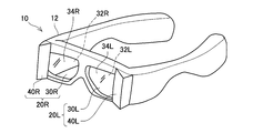
- FIG. 1 shows an appearance of a head mounted display according to a first embodiment.
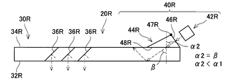
- BRIEF DESCRIPTION OF THE DRAWINGS The structure of the image forming apparatus of 1st Example is shown typically.
- the structure of the image forming apparatus of the 1st modification of 1st Example is shown typically.
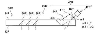
- the structure of the image forming apparatus of the 2nd modification of 1st Example is shown typically.
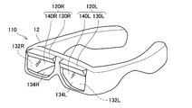
- the external appearance of the head mounted display of 2nd Example is shown.
- the head-mounted display device 10 illustrated in FIG. 1 is a display device (so-called head mounted display) used by being attached to the head of a user.
- the head mounted display 10 is referred to as a “display 10”.
- the display device 10 includes a frame 12, a right image forming device 20R, and a left image forming device 20L.
- the frame 12 shown in FIG. 1 is an eyeglass frame-like member.
- the user can wear the display device 10 on the head by wearing the frame 12 so as to wear glasses.
- the frame 12 may be a headband-like member, a helmet-like member, or any other frame that can be worn on the head.
- the right image forming device 20R is a device for making the right eye of a user wearing the frame 12 visually recognize a display image for the right eye (hereinafter, referred to as “right eye image”).
- the right image forming device 20R includes a right light guide plate 30R and a right projector 40R.
- the left image forming apparatus 20L is an apparatus for causing the left eye of the user wearing the frame 12 to visually recognize a display image for the left eye (hereinafter, referred to as “image for left eye”).
- the left image forming device 20L includes a left light guide plate 30L and a left projector 40L.
- the configurations of the left light guide plate 30L and the left projection device 40L are substantially the same as the configurations of the right light guide plate 30R and the right projection device 40R, except that the left and right are opposite. Therefore, hereinafter, when the right image forming apparatus 20R and the left image forming apparatus 20L are referred to without distinction, they are simply referred to as the "image forming apparatus 20", and the right light guide plate 30R and the left light guide plate 30L are not distinguished. When it calls it, it may only call it the "light guide plate 30", and when calling the right projector 40R and the left projector 40L without distinction, it may only call it the "projector 40.”
- the configuration of the right image forming apparatus 20R will be described below with reference to FIG.
- the left image forming apparatus 20L has substantially the same configuration as the right image forming apparatus 20R except that the left and right are opposite, so the configuration of the right image forming apparatus 20R will be described in detail below, and the configuration of the left image forming apparatus 20L Detailed explanation is omitted about.
- the right light guide plate 30R is a translucent substrate.
- the right light guide plate 30R is formed of, for example, glass. In another example, the right light guide plate 30R may be formed of a light transmissive resin material or the like. When the user wears the display device 10 on the head, the right light guide plate 30R is disposed at a position facing the range including the right eye RE in the user's face.
- the right light guide plate 30R has a first main surface 32R that is a main surface facing the user's face (that is, the right eye RE) and a main surface that is opposite to the first main surface 32R (that is, a side farther from the face). And the second main surface 34R.
- the right light guide plate 30R guides the light incident inside from the right projection device 40R by totally reflecting the inner surface of the first main surface 32R and the inner surface of the second main surface 34R, and then transmits the light to the right eye RE. Make it emit towards (see the broken arrow in FIG. 2).
- a plurality of half mirror members 36R are provided in the right light guide plate 30R.
- three half mirror members 36R are provided inside the right light guide plate 30R, but in the other example, the number of half mirror members 36R is two or more, and any number may be used. It may be.
- the plurality of half mirror members 36R are arranged side by side along a direction from the side where the right projection device 40R is provided (i.e., the outside of the face) toward the center side of the user's face.
- Each of the plurality of half mirror members 36R reflects a part of the light guided in the right light guide plate 30R, transmits the other part, and emits the reflected light toward the right eye RE It is.
- Each half mirror member 36R is a structure in which dielectric films such as SiO 2 and TiO 2 are laminated.
- the half mirror members 36R are disposed to form a predetermined angle with the first major surface 32R of the right light guide plate 30R, and are disposed in parallel at equal intervals.
- the right projection device 40R is disposed at a portion near the user's ear among positions near the outer peripheral edge of the second major surface 34R of the right light guide plate 30R.
- the right projector 40R may be rephrased as being disposed at a position on the outside of the user's face on the second major surface 34R of the right light guide plate 30R.
- the right projector 40R is a projector for emitting light forming an image for the right eye toward the inside of the right light guide plate 30R.
- the image for the right eye is an image showing a portion corresponding to the view range of the right eye in one target image to be visually recognized by the user.
- the right projector 40R includes a light source 42R and a prism 44R.
- the light source 42R is a light source for emitting light representing the above-described right-eye image.
- the light source 42R includes an LED (abbreviation for light emitting diode) panel (not shown), a liquid crystal on silicon (LCOS) panel, and an optical element (for example, a lens or the like).
- the light source 42R can emit light in various modes in accordance with an instruction of a control unit (not shown) mounted on the frame 12.
- the prism 44R is disposed on the second major surface 34R of the right light guide plate 30R.
- the prism 44R is a light guiding optical element for introducing the light emitted from the light source 42R into the right light guide plate 30R after passing the light.
- the prism 44R is formed in a triangular prism shape.
- the prism 44R has an entrance surface 46R and an exit surface 48R.
- the incident surface 46R is a surface on which the light from the light source 42R is incident. As shown in FIG. 2, the incident surface 46R is disposed to be orthogonal to the chief ray of light (including parallel light and diffused light) emitted from the light source 42R.
- the light source 42R is disposed at a position where light can be incident perpendicularly to the incident surface 46R.
- the incident surface 46R is arranged to form a large angle with the second major surface 34R.
- the emission surface 48R is a surface in contact with the second major surface 34R, and is a surface on the side from which the light passing through the inside of the prism 44R is emitted toward the right light guide plate 30R.
- the incident surface 46R and the exit surface 48R form a predetermined angle.
- the end 47R of the incident surface 46R of the prism 44R protrudes in a direction away from the user's face (that is, in the direction from the first major surface 32R to the second major surface 34R).
- the end 47R is disposed to the outside of the field of view of the right eye RE of the user.
- the prism 44R may be formed in a polyhedron shape other than the triangular prism shape, as long as it has an incident surface and an exit surface having the above-described features.
- the prism 44R is formed of a light transmitting resin material.
- the prism 44R may be made of glass.
- the prism 44R is formed of a material having physical properties different from those of the right light guide plate 30R.
- materials of the prism 44R and the right light guide plate 30R are selected so that the refractive index of the prism 44R is smaller than the refractive index of the right light guide plate 30R.
- the "refractive index" is an absolute refractive index.
- the incident surface 46R is disposed to be orthogonal to the chief ray of light (including parallel light and diffused light) emitted from the light source 42R. That is, the light source 42R is disposed at a position where light can be incident perpendicularly to the incident surface 46R. As shown in FIG. 2, in the present embodiment, the end 47R of the incident surface 46R of the prism 44R is disposed outside the field of view of the right eye RE of the user, and the incident surface 46R is larger than the second major surface 34R. Arranged to form an angle. Therefore, the light source 42R is disposed at a position near the second major surface 34R (a position near the right light guide plate 30R).
- FIG. 2 a path through which light emitted from the light source 42R (that is, light representing an image for the right eye) passes in the right image forming device 20R of this embodiment will be described.
- the light is schematically shown by a broken line.
- the light emitted from the light source 42R is introduced into the prism 44R via the incident surface 46R.
- the light introduced into the prism 44R passes through the prism 44R, is emitted from the emission surface 48R, and is incident into the right light guide plate 30R via the second main surface 34R in contact with the emission surface 48R. At this time, the light is refracted at the interface between the exit surface 48R and the second major surface 34R.
- the incident angle when light is incident from the prism 44R to the right light guide plate 30R is represented by ⁇ 1
- the refraction angle when light is incident from the prism 44R to the right light guide plate 30R is represented by ⁇ .
- the incident angle is an angle formed by a line perpendicular to the boundary surface between the prism 44R and the right light guide plate 30R (the alternate long and short dashed line in the figure) and the incident light at the point of incidence of light on the right light guide plate 30R.
- the refraction angle is an angle formed by a line perpendicular to the boundary surface and the light in the right light guide plate 30R.
- the refractive index of the prism 44R is smaller than the refractive index of the right light guide plate 30R. Therefore, the incident angle ⁇ 1 is larger than the refraction angle ⁇ .
- the light incident on the right light guide plate 30R is directed inward from the outside of the face while totally reflecting the inner surface of the first main surface 32R and the inner surface of the second main surface 34R (that is, the right eye RE from the user's right ear Light) along the direction of
- the light guided in the right light guide plate 30R is partially reflected by the plurality of half mirror members 36R and partially transmitted.
- the light reflected by each half mirror member 36R is emitted toward the right eye RE.
- an image for the right eye is formed on the retina of the right eye RE.
- the right eye RE of the user can visually recognize the image for the right eye.
- the left image forming apparatus 20L has substantially the same configuration as the right image forming apparatus 20R except that the right and left sides are opposite. Also in the left image forming apparatus 20L, light is incident on the left light guide plate 30L from the light source through the same path as described above, and an image for the left eye is formed on the retina of the user's left eye. Images can be viewed visually. The user can visually recognize one target image by visually recognizing the right-eye image with the right eye RE and visually recognizing the left-eye image with the left eye.
- the display device 10 of the present embodiment has been described above.
- the right projector 40R is disposed on the second main surface 34R side of the right light guide plate 30R. Therefore, the right projector 40R and the face of the user do not interfere with each other. Therefore, in the display device 10 according to the present embodiment, the right light guide plate 30R does not have to extend laterally to the outside of the face of the user.
- the right light guide plate 30R can be miniaturized as compared with the conventional configuration in which the projection device is disposed on the first main surface side (that is, the configuration in which the light guide plate needs to extend to the outside of the face). Therefore, the entire display device 10 can be miniaturized as compared with the conventional case.
- the refractive index of the prism 44R is smaller than the refractive index of the right light guide plate 30R. Therefore, the incident angle ⁇ 1 is larger than the refraction angle ⁇ . In addition, when the refractive index of the prism 44R is decreased, the incident angle ⁇ 1 is increased. Therefore, the end 47R (that is, the end far from the user's face) of the incident surface 46R of the prism 44R can be disposed outside the field of view of the user. Thereby, it is possible to make it difficult for the right projector 40R to enter the field of view of the user.
- the right projection device 40R is disposed at a portion near the outer peripheral edge of the second main surface 34R of the right light guide plate 30R near the user's right ear.
- the left projection device 40L is also disposed at a portion near the outer periphery of the second major surface 34L of the left light guide plate 30L near the user's left ear.
- the load due to the weight of the projection device 40 is mainly applied to the ear, which can reduce the local application of the load to a part of the user's face. Also, the possibility that the projection device 40 disturbs the user's view may be reduced. Therefore, it is possible to realize the display device 10 that can be used comfortably by the user at the time of wearing.
- FIG. 3 A modification of the display device 10 of the first embodiment will be described with reference to FIG.
- the basic configuration of the display device 10 of the present modification is also common to the display device 10 of FIGS. 1 and 2.
- the configuration of the prism 44R is different from that in FIG.
- the prism 44R (see FIG. 3) of this modification is formed of a material (that is, the same material) having the same physical properties as the right light guide plate 30R. Therefore, in the present modification, the prism 44R and the right light guide plate 30R are formed such that the refractive index of the prism 44R and the refractive index of the right light guide plate 30R are equal.
- the incident angle ⁇ 2 is equal to the refraction angle ⁇ .
- the refraction angle ⁇ in FIG. 3 is the same angle as the refraction angle ⁇ in FIG.
- the incident angle ⁇ 2 of this modification is smaller than the incident angle ⁇ 1 of FIG.
- the incident angle ⁇ 2 is smaller than the incident angle ⁇ 1 in the case of FIG. Due to this characteristic, as shown in FIG. 3, in the present modification, the end 47R of the incident surface 46R of the prism 44R is slightly forward of the end 47R of FIG. 2 (from the right light guide plate 30R (Protruding away from the face of the person) and at a position closer to the center of the face. Along with this, the light source 42R is also disposed at a position projecting slightly forward.
- FIG. 4 Modification 2 of the first embodiment; FIG. 4
- the basic configuration of the display device 10 of the present modification is also common to the display device 10 of FIGS.
- the configuration of the prism 44R is different from that in FIGS. 2 and 3.
- the prism 44R (FIG. 4) of this modification is formed of a material (that is, the same material) having physical properties different from those of the right light guide plate 30R.
- each material of the prism 44R and the right light guide plate 30R is selected such that the refractive index of the prism 44R is larger than the refractive index of the right light guide plate 30R.
- the incident angle ⁇ 3 is smaller than the refraction angle ⁇ .
- the incident angle ⁇ 3 of the present embodiment is smaller than the incident angle ⁇ 2 of FIG.
- the refraction angle ⁇ in FIG. 4 is the same as the refraction angle ⁇ in FIGS. 2 and 3.
- the incident angle ⁇ 3 is smaller than the incident angle ⁇ 2 in the case of FIG. 3 (and the incident angle ⁇ 1 in the case of FIG. 2). Due to this characteristic, as shown in FIG. 4, in the present modification, the end 47R of the incident surface 46R of the prism 44R is slightly further forward than the end 47R of FIG. 3 (in a direction away from the user's face ) And at a position closer to the center of the face. Along with this, the light source 42R is disposed at a position projecting further forward. In this modification, therefore, it is possible to suppress the right projector 40R from interfering with other surrounding members (for example, the eaves of a hat worn by the user, etc.).
- FIG. 5 (Second embodiment; FIG. 5)
- the display device 110 according to the second embodiment will be described with reference to FIG. 5, focusing on differences from the first embodiment.
- the configuration of the right image forming apparatus 120R and the configuration of the left image forming apparatus 120L are different from those of the first embodiment.
- the right image forming device 120R includes the right light guide plate 130R and the right projection device 140R
- the left image forming device 120L includes the left light guide plate 130L and the left projection device 140L
- the left image forming apparatus 120L has substantially the same configuration as the right image forming apparatus 120R except that the left and right are opposite, so the configuration of the right image forming apparatus 120R will be described in detail below. The detailed description of the configuration of the forming apparatus 120L is omitted.
- the right light guide plate 130R of this embodiment also has a first main surface 132R which is a main surface facing the user's face and a second main surface 134R which is a main surface opposite to the first main surface 132R.
- a plurality of half mirror members are provided inside the right light guide plate 130R.
- the plurality of half mirror members are arranged side by side along the direction from the side where the right projection device 140R is provided (that is, the upper side of the face) to the lower side.
- the right projector 140R of the present embodiment is an upper portion (i.e., closer to the user's eyebrows) when the second main surface 34 is viewed from the front among positions near the outer peripheral edge of the second main surface 34R of the right light guide plate 30R. Side edge).
- the right projector 140R of the present embodiment is also a projector for emitting light for forming an image for the right eye toward the inside of the right light guide plate 30R. Therefore, although not shown, the right projector 140R of this embodiment also includes a light source for emitting light representing the image for the right eye, and a prism for introducing the light emitted from the light source into the right light guide plate 130R. Have. Also in this embodiment, the prism is disposed on the second major surface 134R of the right light guide plate 130R.
- the material of the prism and the right light guide plate 130R is selected so that the refractive index of the prism is larger than the refractive index of the right light guide plate 130R.
- the end of the incident surface of the prism protrudes relatively forward, and the center of the right light guide plate 130R is Orientation). Therefore, for example, when the user wears a hat or the like together with the display device 110, as shown in FIG. 4, by adopting a configuration in which the incident angle ⁇ 3 is smaller than the incident angle ⁇ 2 (FIG. 3) There is also an advantage that it becomes difficult to interfere with the projection of the right projection device 140R.
- the material of the prism and the right light guide plate 130R is selected so that the refractive index of the prism is smaller than the refractive index of the right light guide plate 130R. It is also good.
- the material of the prism and the right light guide plate 130R is selected so that the refractive index of the prism is smaller than the refractive index of the right light guide plate 130R. It is also good.
- the prism and the right light guide plate 130R are formed of the same material so that the refractive index of the prism is equal to the refractive index of the right light guide plate 130R. Good.
- the projection device 40 is disposed near the outer peripheral edge of the second main surface 34 of the light guide plate 30 and in a portion close to the user's ear (see FIG. 1).
- the projection device 140 is closer to the outer peripheral edge of the second main surface 134 of the light guide plate 130, and is an upper part when viewed from the front of the second main surface 34 (i.e. It is disposed at the near end (see FIG. 5).
- the arrangement position of a projection apparatus is not restricted to these, As long as it is a position near the outer periphery among 2nd main surfaces of a light-guide plate, it can arrange
- the projection device may be disposed near the outer periphery of the second main surface of the light guide plate and in a portion close to the user's eyebrow.
- the projection device may be disposed closer to the outer peripheral edge of the second main surface of the light guide plate and in the lower portion (i.e., near the lower end of the user's pupil).
- the display devices 10 and 110 are provided with two image forming devices, that is, the right image forming devices 20R and 120R and the left image forming devices 20L and 120L.
- the present invention is not limited to this, and the display device may include only one image forming apparatus (for example, only one for right eye and one for left eye).
- the projection devices 40 and 140 are provided with a prism.
- the light guiding optical element provided in the projection device is not limited to this, and it is optional as long as it can be disposed on the second main surface of the light guide plate and introduce the light emitted from the light source into the light guide plate.
- Other elements for example, a lens may be used.
Abstract
La présente invention concerne un visiocasque pourvu d'un cadre qui peut être installé sur la tête d'un utilisateur, et un dispositif de formation d'image ménagé dans le cadre. Le dispositif de formation d'image comprend : une plaque de guidage de lumière qui est disposée à une position faisant face à une partie, comprenant les yeux, du visage de l'utilisateur et est destinée à guider la lumière incidente dans celle-ci par réflexion totale de la lumière au niveau des surfaces internes de deux surfaces principales, et émettre de la lumière vers les yeux, les deux surfaces principales comprenant une première surface principale faisant face à la partie du visage et une seconde surface principale sur le côté opposé de la première surface principale; et un dispositif de projection disposé à proximité d'un bord circonférentiel externe sur la seconde surface principale de la plaque de guidage de lumière et rayonnant, vers l'intérieur de la plaque de guidage de lumière, une lumière qui forme une image cible. Le dispositif de projection comporte : une source de lumière pour rayonner la lumière qui forme l'image cible; et un élément optique de guidage de lumière pour introduire, à l'intérieur de la plaque de guidage de lumière, la lumière émise par la source de lumière. L'élément optique de guidage de lumière est disposé sur la seconde surface principale de la plaque de guidage de lumière.
Priority Applications (2)
| Application Number | Priority Date | Filing Date | Title |
|---|---|---|---|
| PCT/JP2017/026355 WO2019016926A1 (fr) | 2017-07-20 | 2017-07-20 | Visiocasque |
| JP2019530315A JPWO2019016926A1 (ja) | 2017-07-20 | 2017-07-20 | 頭部装着型表示装置 |
Applications Claiming Priority (1)
| Application Number | Priority Date | Filing Date | Title |
|---|---|---|---|
| PCT/JP2017/026355 WO2019016926A1 (fr) | 2017-07-20 | 2017-07-20 | Visiocasque |
Publications (1)
| Publication Number | Publication Date |
|---|---|
| WO2019016926A1 true WO2019016926A1 (fr) | 2019-01-24 |
Family
ID=65016392
Family Applications (1)
| Application Number | Title | Priority Date | Filing Date |
|---|---|---|---|
| PCT/JP2017/026355 WO2019016926A1 (fr) | 2017-07-20 | 2017-07-20 | Visiocasque |
Country Status (2)
| Country | Link |
|---|---|
| JP (1) | JPWO2019016926A1 (fr) |
| WO (1) | WO2019016926A1 (fr) |
Citations (4)
| Publication number | Priority date | Publication date | Assignee | Title |
|---|---|---|---|---|
| JP2010224479A (ja) * | 2009-03-25 | 2010-10-07 | Olympus Corp | 頭部装着型画像表示装置 |
| JP2013210633A (ja) * | 2000-06-05 | 2013-10-10 | Lumus Ltd | 基板によって誘導される光学ビーム拡大器 |
| WO2016048729A1 (fr) * | 2014-09-24 | 2016-03-31 | Microsoft Technology Licensing, Llc | Suivi oculaire par guide d'onde utilisant des réseaux de diffraction commutables |
| JP2017049289A (ja) * | 2015-08-31 | 2017-03-09 | セイコーエプソン株式会社 | 導光装置及び虚像表示装置 |
-
2017
- 2017-07-20 JP JP2019530315A patent/JPWO2019016926A1/ja active Pending
- 2017-07-20 WO PCT/JP2017/026355 patent/WO2019016926A1/fr active Application Filing
Patent Citations (4)
| Publication number | Priority date | Publication date | Assignee | Title |
|---|---|---|---|---|
| JP2013210633A (ja) * | 2000-06-05 | 2013-10-10 | Lumus Ltd | 基板によって誘導される光学ビーム拡大器 |
| JP2010224479A (ja) * | 2009-03-25 | 2010-10-07 | Olympus Corp | 頭部装着型画像表示装置 |
| WO2016048729A1 (fr) * | 2014-09-24 | 2016-03-31 | Microsoft Technology Licensing, Llc | Suivi oculaire par guide d'onde utilisant des réseaux de diffraction commutables |
| JP2017049289A (ja) * | 2015-08-31 | 2017-03-09 | セイコーエプソン株式会社 | 導光装置及び虚像表示装置 |
Also Published As
| Publication number | Publication date |
|---|---|
| JPWO2019016926A1 (ja) | 2020-05-21 |
Similar Documents
| Publication | Publication Date | Title |
|---|---|---|
| JP7190337B2 (ja) | 回折光学レンズを具備した多重映像ディスプレイ装置 | |
| US10107994B2 (en) | Wide field-of-view virtual image projector | |
| US9298001B2 (en) | Optical configurations for head worn computing | |
| WO2015154643A1 (fr) | Affichage transmissif de lunettes | |
| JP2018502328A (ja) | 光結合を用いたヘッドマウント型画像装置 | |
| US11619816B2 (en) | Head-mounted display | |
| CN112230435A (zh) | 光学系统和可穿戴设备 | |
| CN107643559A (zh) | 基于反射式波导耦合器的光线传导和分离方法及装置 | |
| US11543648B2 (en) | Virtual image projection device | |
| CN112462519A (zh) | 一种出光均匀的光栅波导显示装置 | |
| JP6822194B2 (ja) | 虚像光学系および虚像表示装置 | |
| TWI669564B (zh) | 鏡頭模組及投影裝置 | |
| WO2019016926A1 (fr) | Visiocasque | |
| US11467417B2 (en) | Display device | |
| KR20220010359A (ko) | 증강 현실 표시 장치 | |
| CN115004080A (zh) | 导光体和虚像显示装置 | |
| US20230030353A1 (en) | Virtual image display device | |
| US20230031714A1 (en) | Virtual image display device | |
| US11940624B2 (en) | Optical device and wearable image display device | |
| CN115248500B (zh) | 扩增实境眼镜 | |
| WO2021232967A1 (fr) | Ensemble d'affichage optique et dispositif vestimentaire intelligent | |
| CN112305761B (zh) | 图像显示装置 | |
| US20220229220A1 (en) | Optical device for augmented reality having improved light transmittance | |
| US11899210B2 (en) | Wearable image display device | |
| WO2024033968A1 (fr) | Système optique de projection et terminal de type lunettes |
Legal Events
| Date | Code | Title | Description |
|---|---|---|---|
| 121 | Ep: the epo has been informed by wipo that ep was designated in this application |
Ref document number: 17918543 Country of ref document: EP Kind code of ref document: A1 |
|
| ENP | Entry into the national phase |
Ref document number: 2019530315 Country of ref document: JP Kind code of ref document: A |
|
| NENP | Non-entry into the national phase |
Ref country code: DE |
|
| 122 | Ep: pct application non-entry in european phase |
Ref document number: 17918543 Country of ref document: EP Kind code of ref document: A1 |