WO2019016926A1 - Head-mounted display apparatus - Google Patents
Head-mounted display apparatus Download PDFInfo
- Publication number
- WO2019016926A1 WO2019016926A1 PCT/JP2017/026355 JP2017026355W WO2019016926A1 WO 2019016926 A1 WO2019016926 A1 WO 2019016926A1 JP 2017026355 W JP2017026355 W JP 2017026355W WO 2019016926 A1 WO2019016926 A1 WO 2019016926A1
- Authority
- WO
- WIPO (PCT)
- Prior art keywords
- light
- guide plate
- light guide
- prism
- incident
- Prior art date
Links
Images

Classifications
-
- G—PHYSICS
- G02—OPTICS
- G02B—OPTICAL ELEMENTS, SYSTEMS OR APPARATUS
- G02B27/00—Optical systems or apparatus not provided for by any of the groups G02B1/00 - G02B26/00, G02B30/00
- G02B27/02—Viewing or reading apparatus
-
- G—PHYSICS
- G09—EDUCATION; CRYPTOGRAPHY; DISPLAY; ADVERTISING; SEALS
- G09F—DISPLAYING; ADVERTISING; SIGNS; LABELS OR NAME-PLATES; SEALS
- G09F9/00—Indicating arrangements for variable information in which the information is built-up on a support by selection or combination of individual elements
-
- H—ELECTRICITY
- H04—ELECTRIC COMMUNICATION TECHNIQUE
- H04N—PICTORIAL COMMUNICATION, e.g. TELEVISION
- H04N5/00—Details of television systems
- H04N5/64—Constructional details of receivers, e.g. cabinets or dust covers
Definitions
- the technology disclosed by the present specification relates to a head mounted display used by being mounted on the head of a user.
- Patent Document 1 Japanese Patent Application Laid-Open No. 2010-48998 discloses a head-mounted display used by being attached to the head of a user.
- This head-mounted display device includes a frame that can be attached to the user's head, and an image forming device provided on the frame.
- the image forming apparatus includes a light guide plate and a projection device.
- the light guide plate is disposed at a position facing a part of the face including the user's eyes, and the light incident on the inside is guided by being totally reflected by the inner surfaces of the two main surfaces, and then toward the eyes It is a board for emitting light.
- the two main surfaces include a first main surface opposite to a part of the face and a second main surface opposite to the first main surface.
- the projection device is a device that emits light that forms an image toward the inside of the light guide plate, and is a position closer to the outer periphery of the first main surface of the light guide plate (that is, the surface facing a part of the face). Will be placed.
- the projection device When adopting the configuration of Patent Document 1 in which the projection device is disposed on the first main surface of the light guide plate, the projection device is selected from the first main surface of the light guide plate to avoid interference between the projection device and the user's face. , It is necessary to provide in the range outside the range which faces a face. Therefore, in order to avoid interference between the projector and the face, the light guide plate needs to extend to the outside of the face. That is, a relatively large light guide plate must be provided, and the entire head-mounted display may be upsized.
- the present specification discloses a technology that can miniaturize the entire head mounted display.
- the head mounted display disclosed by the present specification includes a frame that can be mounted on the user's head, and an image forming device provided on the frame.
- the image forming apparatus is disposed at a position facing a part of the face including the eyes of the user, and the light incident inside is guided by being totally reflected by the inner surfaces of the two main surfaces, A light guide plate for emitting light toward the eye, wherein the two main surfaces are a first main surface opposite to a part of the face and a second main surface opposite to the first main surface.
- a projection device disposed at a position near the outer peripheral edge of the light guide plate including the surface and the second main surface of the light guide plate and emitting light toward the inside of the light guide plate to form a target image And have.
- the projection apparatus includes a light source for irradiating the light forming the target image, and a light guiding optical element for introducing the light emitted from the light source into the light guide plate. There is.
- the light guide optical element is disposed on the second main surface of the light guide plate.
- the projection device since the projection device is disposed on the second main surface side, the projection device and the face of the user do not interfere with each other. Therefore, the light guide plate does not have to extend to the outside of the face.
- the light guide plate can be miniaturized as compared with the conventional configuration in which the projection device is disposed on the first main surface side (that is, the configuration in which the light guide plate needs to extend to the outside of the face). Therefore, the entire head mounted display can be miniaturized as compared with the conventional case.
- the light guiding optical element may include a prism for introducing the light emitted from the light source into the light guide plate after passing the light.
- the prism is an incident surface on which light from the light source is incident, and an exit surface in contact with the second main surface of the light guide plate and from which light passing through the prism is emitted to the light guide plate,
- the light emitting device may have a polyhedral shape having the light emitting surface provided so as to form a predetermined angle with the light receiving surface.
- the incident angle when light is incident on the light guide plate from the prism may be equal to or less than the refraction angle when light is incident on the light guide plate from the prism.
- the projection apparatus can be prevented from interfering with other surrounding members (for example, the eaves of a hat worn by the user).
- incident angle refers to an angle formed by a line perpendicular to the boundary surface between the prism and the light guide plate and the incident light at the light incident point to the light guide plate.
- refractive angle is an angle formed by a line perpendicular to the boundary surface and the light in the light guide plate.
- the light guiding optical element may include a prism for introducing the light emitted from the light source into the light guide plate after passing the light.
- the prism is an incident surface on which light from the light source is incident, and an exit surface in contact with the second main surface of the light guide plate and from which light passing through the prism is emitted to the light guide plate,
- the light emitting device may have a polyhedral shape having the light emitting surface provided so as to form a predetermined angle with the light receiving surface.
- the incident angle when light is incident on the light guide plate from the prism may be equal to or greater than the refraction angle when light is incident on the light guide plate from the prism.
- the angle of incidence is equal to or greater than the angle of refraction, it is possible to place the end of the incident surface of the prism (that is, the end farther from the user's face) closer to the user's view. it can. Therefore, it is possible to make it difficult for the projection device to enter the field of view of the user.
- the angle of incidence may be equal to the angle of refraction.
- the incident angle and the refracting angle are equal to each other, light is not reflected at the boundary between the prism and the light guide plate when light is incident from the prism to the light guide plate. Therefore, the light quantity loss can be reduced.
- the projection apparatus may be disposed at an upper portion of the positions near the outer peripheral edge of the second main surface of the light guide plate when the second main surface is viewed in front.
- This configuration can reduce the possibility that the projection device may disturb the user's view. Therefore, it is possible to realize a head-mounted display that can be used comfortably by the user at the time of wearing.
- the projection device may be disposed at a portion closer to the user's ear among the positions near the outer peripheral edge of the second main surface of the light guide plate.
- the load due to the weight of the projection device is mainly applied to the ear, which can reduce the application of the load locally on a part of the user's face. It may also reduce the likelihood that the projection device will interfere with the user's view. Therefore, it is possible to realize a head-mounted display that can be used comfortably by the user at the time of wearing.
- FIG. 1 shows an appearance of a head mounted display according to a first embodiment.
- BRIEF DESCRIPTION OF THE DRAWINGS The structure of the image forming apparatus of 1st Example is shown typically.
- the structure of the image forming apparatus of the 1st modification of 1st Example is shown typically.
- the structure of the image forming apparatus of the 2nd modification of 1st Example is shown typically.
- the external appearance of the head mounted display of 2nd Example is shown.
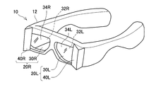
- the head-mounted display device 10 illustrated in FIG. 1 is a display device (so-called head mounted display) used by being attached to the head of a user.
- the head mounted display 10 is referred to as a “display 10”.
- the display device 10 includes a frame 12, a right image forming device 20R, and a left image forming device 20L.
- the frame 12 shown in FIG. 1 is an eyeglass frame-like member.
- the user can wear the display device 10 on the head by wearing the frame 12 so as to wear glasses.
- the frame 12 may be a headband-like member, a helmet-like member, or any other frame that can be worn on the head.
- the right image forming device 20R is a device for making the right eye of a user wearing the frame 12 visually recognize a display image for the right eye (hereinafter, referred to as “right eye image”).
- the right image forming device 20R includes a right light guide plate 30R and a right projector 40R.
- the left image forming apparatus 20L is an apparatus for causing the left eye of the user wearing the frame 12 to visually recognize a display image for the left eye (hereinafter, referred to as “image for left eye”).
- the left image forming device 20L includes a left light guide plate 30L and a left projector 40L.
- the configurations of the left light guide plate 30L and the left projection device 40L are substantially the same as the configurations of the right light guide plate 30R and the right projection device 40R, except that the left and right are opposite. Therefore, hereinafter, when the right image forming apparatus 20R and the left image forming apparatus 20L are referred to without distinction, they are simply referred to as the "image forming apparatus 20", and the right light guide plate 30R and the left light guide plate 30L are not distinguished. When it calls it, it may only call it the "light guide plate 30", and when calling the right projector 40R and the left projector 40L without distinction, it may only call it the "projector 40.”
- the configuration of the right image forming apparatus 20R will be described below with reference to FIG.
- the left image forming apparatus 20L has substantially the same configuration as the right image forming apparatus 20R except that the left and right are opposite, so the configuration of the right image forming apparatus 20R will be described in detail below, and the configuration of the left image forming apparatus 20L Detailed explanation is omitted about.
- the right light guide plate 30R is a translucent substrate.
- the right light guide plate 30R is formed of, for example, glass. In another example, the right light guide plate 30R may be formed of a light transmissive resin material or the like. When the user wears the display device 10 on the head, the right light guide plate 30R is disposed at a position facing the range including the right eye RE in the user's face.
- the right light guide plate 30R has a first main surface 32R that is a main surface facing the user's face (that is, the right eye RE) and a main surface that is opposite to the first main surface 32R (that is, a side farther from the face). And the second main surface 34R.
- the right light guide plate 30R guides the light incident inside from the right projection device 40R by totally reflecting the inner surface of the first main surface 32R and the inner surface of the second main surface 34R, and then transmits the light to the right eye RE. Make it emit towards (see the broken arrow in FIG. 2).
- a plurality of half mirror members 36R are provided in the right light guide plate 30R.
- three half mirror members 36R are provided inside the right light guide plate 30R, but in the other example, the number of half mirror members 36R is two or more, and any number may be used. It may be.
- the plurality of half mirror members 36R are arranged side by side along a direction from the side where the right projection device 40R is provided (i.e., the outside of the face) toward the center side of the user's face.
- Each of the plurality of half mirror members 36R reflects a part of the light guided in the right light guide plate 30R, transmits the other part, and emits the reflected light toward the right eye RE It is.
- Each half mirror member 36R is a structure in which dielectric films such as SiO 2 and TiO 2 are laminated.
- the half mirror members 36R are disposed to form a predetermined angle with the first major surface 32R of the right light guide plate 30R, and are disposed in parallel at equal intervals.
- the right projection device 40R is disposed at a portion near the user's ear among positions near the outer peripheral edge of the second major surface 34R of the right light guide plate 30R.
- the right projector 40R may be rephrased as being disposed at a position on the outside of the user's face on the second major surface 34R of the right light guide plate 30R.
- the right projector 40R is a projector for emitting light forming an image for the right eye toward the inside of the right light guide plate 30R.
- the image for the right eye is an image showing a portion corresponding to the view range of the right eye in one target image to be visually recognized by the user.
- the right projector 40R includes a light source 42R and a prism 44R.
- the light source 42R is a light source for emitting light representing the above-described right-eye image.
- the light source 42R includes an LED (abbreviation for light emitting diode) panel (not shown), a liquid crystal on silicon (LCOS) panel, and an optical element (for example, a lens or the like).
- the light source 42R can emit light in various modes in accordance with an instruction of a control unit (not shown) mounted on the frame 12.
- the prism 44R is disposed on the second major surface 34R of the right light guide plate 30R.
- the prism 44R is a light guiding optical element for introducing the light emitted from the light source 42R into the right light guide plate 30R after passing the light.
- the prism 44R is formed in a triangular prism shape.
- the prism 44R has an entrance surface 46R and an exit surface 48R.
- the incident surface 46R is a surface on which the light from the light source 42R is incident. As shown in FIG. 2, the incident surface 46R is disposed to be orthogonal to the chief ray of light (including parallel light and diffused light) emitted from the light source 42R.
- the light source 42R is disposed at a position where light can be incident perpendicularly to the incident surface 46R.
- the incident surface 46R is arranged to form a large angle with the second major surface 34R.
- the emission surface 48R is a surface in contact with the second major surface 34R, and is a surface on the side from which the light passing through the inside of the prism 44R is emitted toward the right light guide plate 30R.
- the incident surface 46R and the exit surface 48R form a predetermined angle.
- the end 47R of the incident surface 46R of the prism 44R protrudes in a direction away from the user's face (that is, in the direction from the first major surface 32R to the second major surface 34R).
- the end 47R is disposed to the outside of the field of view of the right eye RE of the user.
- the prism 44R may be formed in a polyhedron shape other than the triangular prism shape, as long as it has an incident surface and an exit surface having the above-described features.
- the prism 44R is formed of a light transmitting resin material.
- the prism 44R may be made of glass.
- the prism 44R is formed of a material having physical properties different from those of the right light guide plate 30R.
- materials of the prism 44R and the right light guide plate 30R are selected so that the refractive index of the prism 44R is smaller than the refractive index of the right light guide plate 30R.
- the "refractive index" is an absolute refractive index.
- the incident surface 46R is disposed to be orthogonal to the chief ray of light (including parallel light and diffused light) emitted from the light source 42R. That is, the light source 42R is disposed at a position where light can be incident perpendicularly to the incident surface 46R. As shown in FIG. 2, in the present embodiment, the end 47R of the incident surface 46R of the prism 44R is disposed outside the field of view of the right eye RE of the user, and the incident surface 46R is larger than the second major surface 34R. Arranged to form an angle. Therefore, the light source 42R is disposed at a position near the second major surface 34R (a position near the right light guide plate 30R).
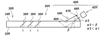
- FIG. 2 a path through which light emitted from the light source 42R (that is, light representing an image for the right eye) passes in the right image forming device 20R of this embodiment will be described.
- the light is schematically shown by a broken line.
- the light emitted from the light source 42R is introduced into the prism 44R via the incident surface 46R.
- the light introduced into the prism 44R passes through the prism 44R, is emitted from the emission surface 48R, and is incident into the right light guide plate 30R via the second main surface 34R in contact with the emission surface 48R. At this time, the light is refracted at the interface between the exit surface 48R and the second major surface 34R.
- the incident angle when light is incident from the prism 44R to the right light guide plate 30R is represented by ⁇ 1
- the refraction angle when light is incident from the prism 44R to the right light guide plate 30R is represented by ⁇ .
- the incident angle is an angle formed by a line perpendicular to the boundary surface between the prism 44R and the right light guide plate 30R (the alternate long and short dashed line in the figure) and the incident light at the point of incidence of light on the right light guide plate 30R.
- the refraction angle is an angle formed by a line perpendicular to the boundary surface and the light in the right light guide plate 30R.
- the refractive index of the prism 44R is smaller than the refractive index of the right light guide plate 30R. Therefore, the incident angle ⁇ 1 is larger than the refraction angle ⁇ .
- the light incident on the right light guide plate 30R is directed inward from the outside of the face while totally reflecting the inner surface of the first main surface 32R and the inner surface of the second main surface 34R (that is, the right eye RE from the user's right ear Light) along the direction of
- the light guided in the right light guide plate 30R is partially reflected by the plurality of half mirror members 36R and partially transmitted.
- the light reflected by each half mirror member 36R is emitted toward the right eye RE.
- an image for the right eye is formed on the retina of the right eye RE.
- the right eye RE of the user can visually recognize the image for the right eye.
- the left image forming apparatus 20L has substantially the same configuration as the right image forming apparatus 20R except that the right and left sides are opposite. Also in the left image forming apparatus 20L, light is incident on the left light guide plate 30L from the light source through the same path as described above, and an image for the left eye is formed on the retina of the user's left eye. Images can be viewed visually. The user can visually recognize one target image by visually recognizing the right-eye image with the right eye RE and visually recognizing the left-eye image with the left eye.
- the display device 10 of the present embodiment has been described above.
- the right projector 40R is disposed on the second main surface 34R side of the right light guide plate 30R. Therefore, the right projector 40R and the face of the user do not interfere with each other. Therefore, in the display device 10 according to the present embodiment, the right light guide plate 30R does not have to extend laterally to the outside of the face of the user.
- the right light guide plate 30R can be miniaturized as compared with the conventional configuration in which the projection device is disposed on the first main surface side (that is, the configuration in which the light guide plate needs to extend to the outside of the face). Therefore, the entire display device 10 can be miniaturized as compared with the conventional case.
- the refractive index of the prism 44R is smaller than the refractive index of the right light guide plate 30R. Therefore, the incident angle ⁇ 1 is larger than the refraction angle ⁇ . In addition, when the refractive index of the prism 44R is decreased, the incident angle ⁇ 1 is increased. Therefore, the end 47R (that is, the end far from the user's face) of the incident surface 46R of the prism 44R can be disposed outside the field of view of the user. Thereby, it is possible to make it difficult for the right projector 40R to enter the field of view of the user.
- the right projection device 40R is disposed at a portion near the outer peripheral edge of the second main surface 34R of the right light guide plate 30R near the user's right ear.
- the left projection device 40L is also disposed at a portion near the outer periphery of the second major surface 34L of the left light guide plate 30L near the user's left ear.
- the load due to the weight of the projection device 40 is mainly applied to the ear, which can reduce the local application of the load to a part of the user's face. Also, the possibility that the projection device 40 disturbs the user's view may be reduced. Therefore, it is possible to realize the display device 10 that can be used comfortably by the user at the time of wearing.
- FIG. 3 A modification of the display device 10 of the first embodiment will be described with reference to FIG.
- the basic configuration of the display device 10 of the present modification is also common to the display device 10 of FIGS. 1 and 2.
- the configuration of the prism 44R is different from that in FIG.
- the prism 44R (see FIG. 3) of this modification is formed of a material (that is, the same material) having the same physical properties as the right light guide plate 30R. Therefore, in the present modification, the prism 44R and the right light guide plate 30R are formed such that the refractive index of the prism 44R and the refractive index of the right light guide plate 30R are equal.
- the incident angle ⁇ 2 is equal to the refraction angle ⁇ .
- the refraction angle ⁇ in FIG. 3 is the same angle as the refraction angle ⁇ in FIG.
- the incident angle ⁇ 2 of this modification is smaller than the incident angle ⁇ 1 of FIG.
- the incident angle ⁇ 2 is smaller than the incident angle ⁇ 1 in the case of FIG. Due to this characteristic, as shown in FIG. 3, in the present modification, the end 47R of the incident surface 46R of the prism 44R is slightly forward of the end 47R of FIG. 2 (from the right light guide plate 30R (Protruding away from the face of the person) and at a position closer to the center of the face. Along with this, the light source 42R is also disposed at a position projecting slightly forward.
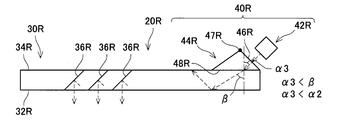
- FIG. 4 Modification 2 of the first embodiment; FIG. 4
- the basic configuration of the display device 10 of the present modification is also common to the display device 10 of FIGS.
- the configuration of the prism 44R is different from that in FIGS. 2 and 3.
- the prism 44R (FIG. 4) of this modification is formed of a material (that is, the same material) having physical properties different from those of the right light guide plate 30R.
- each material of the prism 44R and the right light guide plate 30R is selected such that the refractive index of the prism 44R is larger than the refractive index of the right light guide plate 30R.
- the incident angle ⁇ 3 is smaller than the refraction angle ⁇ .
- the incident angle ⁇ 3 of the present embodiment is smaller than the incident angle ⁇ 2 of FIG.
- the refraction angle ⁇ in FIG. 4 is the same as the refraction angle ⁇ in FIGS. 2 and 3.
- the incident angle ⁇ 3 is smaller than the incident angle ⁇ 2 in the case of FIG. 3 (and the incident angle ⁇ 1 in the case of FIG. 2). Due to this characteristic, as shown in FIG. 4, in the present modification, the end 47R of the incident surface 46R of the prism 44R is slightly further forward than the end 47R of FIG. 3 (in a direction away from the user's face ) And at a position closer to the center of the face. Along with this, the light source 42R is disposed at a position projecting further forward. In this modification, therefore, it is possible to suppress the right projector 40R from interfering with other surrounding members (for example, the eaves of a hat worn by the user, etc.).
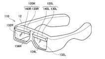
- FIG. 5 (Second embodiment; FIG. 5)
- the display device 110 according to the second embodiment will be described with reference to FIG. 5, focusing on differences from the first embodiment.
- the configuration of the right image forming apparatus 120R and the configuration of the left image forming apparatus 120L are different from those of the first embodiment.
- the right image forming device 120R includes the right light guide plate 130R and the right projection device 140R
- the left image forming device 120L includes the left light guide plate 130L and the left projection device 140L
- the left image forming apparatus 120L has substantially the same configuration as the right image forming apparatus 120R except that the left and right are opposite, so the configuration of the right image forming apparatus 120R will be described in detail below. The detailed description of the configuration of the forming apparatus 120L is omitted.
- the right light guide plate 130R of this embodiment also has a first main surface 132R which is a main surface facing the user's face and a second main surface 134R which is a main surface opposite to the first main surface 132R.
- a plurality of half mirror members are provided inside the right light guide plate 130R.
- the plurality of half mirror members are arranged side by side along the direction from the side where the right projection device 140R is provided (that is, the upper side of the face) to the lower side.
- the right projector 140R of the present embodiment is an upper portion (i.e., closer to the user's eyebrows) when the second main surface 34 is viewed from the front among positions near the outer peripheral edge of the second main surface 34R of the right light guide plate 30R. Side edge).
- the right projector 140R of the present embodiment is also a projector for emitting light for forming an image for the right eye toward the inside of the right light guide plate 30R. Therefore, although not shown, the right projector 140R of this embodiment also includes a light source for emitting light representing the image for the right eye, and a prism for introducing the light emitted from the light source into the right light guide plate 130R. Have. Also in this embodiment, the prism is disposed on the second major surface 134R of the right light guide plate 130R.
- the material of the prism and the right light guide plate 130R is selected so that the refractive index of the prism is larger than the refractive index of the right light guide plate 130R.
- the end of the incident surface of the prism protrudes relatively forward, and the center of the right light guide plate 130R is Orientation). Therefore, for example, when the user wears a hat or the like together with the display device 110, as shown in FIG. 4, by adopting a configuration in which the incident angle ⁇ 3 is smaller than the incident angle ⁇ 2 (FIG. 3) There is also an advantage that it becomes difficult to interfere with the projection of the right projection device 140R.
- the material of the prism and the right light guide plate 130R is selected so that the refractive index of the prism is smaller than the refractive index of the right light guide plate 130R. It is also good.
- the material of the prism and the right light guide plate 130R is selected so that the refractive index of the prism is smaller than the refractive index of the right light guide plate 130R. It is also good.
- the prism and the right light guide plate 130R are formed of the same material so that the refractive index of the prism is equal to the refractive index of the right light guide plate 130R. Good.
- the projection device 40 is disposed near the outer peripheral edge of the second main surface 34 of the light guide plate 30 and in a portion close to the user's ear (see FIG. 1).
- the projection device 140 is closer to the outer peripheral edge of the second main surface 134 of the light guide plate 130, and is an upper part when viewed from the front of the second main surface 34 (i.e. It is disposed at the near end (see FIG. 5).
- the arrangement position of a projection apparatus is not restricted to these, As long as it is a position near the outer periphery among 2nd main surfaces of a light-guide plate, it can arrange
- the projection device may be disposed near the outer periphery of the second main surface of the light guide plate and in a portion close to the user's eyebrow.
- the projection device may be disposed closer to the outer peripheral edge of the second main surface of the light guide plate and in the lower portion (i.e., near the lower end of the user's pupil).
- the display devices 10 and 110 are provided with two image forming devices, that is, the right image forming devices 20R and 120R and the left image forming devices 20L and 120L.
- the present invention is not limited to this, and the display device may include only one image forming apparatus (for example, only one for right eye and one for left eye).
- the projection devices 40 and 140 are provided with a prism.
- the light guiding optical element provided in the projection device is not limited to this, and it is optional as long as it can be disposed on the second main surface of the light guide plate and introduce the light emitted from the light source into the light guide plate.
- Other elements for example, a lens may be used.
Landscapes
- Physics & Mathematics (AREA)
- General Physics & Mathematics (AREA)
- Engineering & Computer Science (AREA)
- Theoretical Computer Science (AREA)
- Optics & Photonics (AREA)
- Multimedia (AREA)
- Signal Processing (AREA)
- Devices For Indicating Variable Information By Combining Individual Elements (AREA)
Abstract
This head-mounted display apparatus is provided with a frame that can be mounted on the head of a user and an image forming device provided in the frame. The image forming device is provided with: a light guide plate which is disposed at a position facing a portion, which includes the eyes, of the face of the user and is for guiding light incident therein by totally reflecting the light at inner surfaces of two main surfaces and then emitting the light toward the eyes, wherein the two main surfaces include a first main surface facing the portion of the face and a second main surface on the reverse side of the first main surface; and a projection device disposed near an outer circumferential edge on the second main surface of the light guide plate and radiating, toward the inside of the light guide plate, light that forms a target image. The projection device is provided with: a light source for radiating the light that forms the target image; and a light guide optical element for introducing, to the inside of the light guide plate, the light emitted from the light source. The light guide optical element is disposed on the second main surface of the light guide plate.
Description
本明細書によって開示される技術は、ユーザの頭部に装着して使用される頭部装着型表示装置に関する。
The technology disclosed by the present specification relates to a head mounted display used by being mounted on the head of a user.
例えば、特開2010-48998号公報(以下特許文献1という)には、ユーザの頭部に装着して使用される頭部装着型表示装置が開示されている。この頭部装着型表示装置は、ユーザの頭部に装着可能なフレームと、フレームに設けられる画像形成装置とを備える。画像形成装置は、導光板と投影装置とを備える。導光板は、ユーザの眼を含む顔の一部に対向する位置に配置され、内部に入射された光を、2つの主面の内面で全反射することによって導光した後、眼に向かって出射させるための板である。2つの主面は、顔の一部に対向する第1主面と、第1主面の反対側の面である第2主面とを含む。投影装置は、導光板の内部に向かって画像を形成する光を照射する装置であって、導光板の第1主面(即ち、顔の一部に対向する面)のうちの外周寄りの位置に配置される。
For example, Japanese Patent Application Laid-Open No. 2010-48998 (hereinafter referred to as Patent Document 1) discloses a head-mounted display used by being attached to the head of a user. This head-mounted display device includes a frame that can be attached to the user's head, and an image forming device provided on the frame. The image forming apparatus includes a light guide plate and a projection device. The light guide plate is disposed at a position facing a part of the face including the user's eyes, and the light incident on the inside is guided by being totally reflected by the inner surfaces of the two main surfaces, and then toward the eyes It is a board for emitting light. The two main surfaces include a first main surface opposite to a part of the face and a second main surface opposite to the first main surface. The projection device is a device that emits light that forms an image toward the inside of the light guide plate, and is a position closer to the outer periphery of the first main surface of the light guide plate (that is, the surface facing a part of the face). Will be placed.
導光板の第1主面に投影装置を配置する特許文献1の構成を採用する場合、投影装置とユーザの顔との干渉を避けるために、投影装置を、導光板の第1主面のうち、顔に対向する範囲よりも外側の範囲に設ける必要がある。そのため、投影装置と顔との干渉を避けるためには、導光板が顔の外側まで延びている必要がある。即ち、比較的大型の導光板を備えなければならず、頭部装着型表示装置全体が大型化する場合があった。
When adopting the configuration of Patent Document 1 in which the projection device is disposed on the first main surface of the light guide plate, the projection device is selected from the first main surface of the light guide plate to avoid interference between the projection device and the user's face. , It is necessary to provide in the range outside the range which faces a face. Therefore, in order to avoid interference between the projector and the face, the light guide plate needs to extend to the outside of the face. That is, a relatively large light guide plate must be provided, and the entire head-mounted display may be upsized.
本明細書では、頭部装着型表示装置全体を小型化し得る技術を開示する。
The present specification discloses a technology that can miniaturize the entire head mounted display.
本明細書によって開示される頭部装着型表示装置は、ユーザの頭部に装着可能なフレームと、前記フレームに設けられる画像形成装置と、を備える。前記画像形成装置は、前記ユーザの眼を含む顔の一部に対向する位置に配置され、内部に入射された光を、2つの主面の内面で全反射することによって導光した後、前記眼に向かって出射させるための導光板であって、前記2つの主面は、前記顔の一部に対向する第1主面と、前記第1主面の反対側の面である第2主面とを含む、前記導光板と、前記導光板の前記第2主面のうちの外周縁寄りの位置に配置され、前記導光板の内部に向かって対象画像を形成する光を照射する投影装置と、を備えている。前記投影装置は、前記対象画像を形成する前記光を照射するための光源と、前記光源から出射された前記光を前記導光板の内部に導入するための導光用光学素子と、を備えている。前記導光用光学素子は、前記導光板の前記第2主面に配置される。
The head mounted display disclosed by the present specification includes a frame that can be mounted on the user's head, and an image forming device provided on the frame. The image forming apparatus is disposed at a position facing a part of the face including the eyes of the user, and the light incident inside is guided by being totally reflected by the inner surfaces of the two main surfaces, A light guide plate for emitting light toward the eye, wherein the two main surfaces are a first main surface opposite to a part of the face and a second main surface opposite to the first main surface. And a projection device disposed at a position near the outer peripheral edge of the light guide plate including the surface and the second main surface of the light guide plate and emitting light toward the inside of the light guide plate to form a target image And have. The projection apparatus includes a light source for irradiating the light forming the target image, and a light guiding optical element for introducing the light emitted from the light source into the light guide plate. There is. The light guide optical element is disposed on the second main surface of the light guide plate.
この構成によると、第2主面側に投影装置が配置されているため、投影装置とユーザの顔とが干渉することがない。そのため、導光板が顔の外側まで延びている必要がない。第1主面側に投影装置を配置する従来の構成(即ち、導光板が顔の外側まで延びている必要がある構成)に比べて、導光板を小型化することができる。そのため、従来に比べて、頭部装着型表示装置全体を小型化することができる。
According to this configuration, since the projection device is disposed on the second main surface side, the projection device and the face of the user do not interfere with each other. Therefore, the light guide plate does not have to extend to the outside of the face. The light guide plate can be miniaturized as compared with the conventional configuration in which the projection device is disposed on the first main surface side (that is, the configuration in which the light guide plate needs to extend to the outside of the face). Therefore, the entire head mounted display can be miniaturized as compared with the conventional case.
前記導光用光学素子は、前記光源から出射された前記光を通過させた後で前記導光板内に導入させるプリズムを含んでもよい。前記プリズムは、前記光源からの光が入射する入射面と、前記導光板の前記第2主面に接するとともに、前記プリズム内を通過した光が前記導光板に出射する出射面であって、前記入射面との間に所定の角度を形成するように設けられる前記出射面と、を有する多面体形状を有していてもよい。前記プリズムから前記導光板に光が入射する際の入射角は、前記プリズムから前記導光板に光が入射する際の屈折角以下であってもよい。
The light guiding optical element may include a prism for introducing the light emitted from the light source into the light guide plate after passing the light. The prism is an incident surface on which light from the light source is incident, and an exit surface in contact with the second main surface of the light guide plate and from which light passing through the prism is emitted to the light guide plate, The light emitting device may have a polyhedral shape having the light emitting surface provided so as to form a predetermined angle with the light receiving surface. The incident angle when light is incident on the light guide plate from the prism may be equal to or less than the refraction angle when light is incident on the light guide plate from the prism.
この構成によると、入射角が屈折角以下であるため、プリズムの入射面の端部(即ち、ユーザの顔から遠い側の端部)を、ユーザの視界の内側寄りに配置することができる。そのため、投影装置が、周囲の他部材(例えば、ユーザが被る帽子のひさし等)と干渉することを抑制し得る。なお、ここで言う「入射角」とは、導光板への光の入射点において、プリズムと導光板との境界面に垂直な線と入射した光とがなす角度のことである。また、「屈折角」とは、上記の境界面に垂直な線と、導光板内の光とがなす角度のことである。
According to this configuration, since the angle of incidence is equal to or less than the angle of refraction, the end of the incident surface of the prism (that is, the end farther from the user's face) can be disposed inward of the user's field of view. Therefore, the projection apparatus can be prevented from interfering with other surrounding members (for example, the eaves of a hat worn by the user). The term “incident angle” as used herein refers to an angle formed by a line perpendicular to the boundary surface between the prism and the light guide plate and the incident light at the light incident point to the light guide plate. The “refractive angle” is an angle formed by a line perpendicular to the boundary surface and the light in the light guide plate.
前記導光用光学素子は、前記光源から出射された前記光を通過させた後で前記導光板内に導入させるプリズムを含んでもよい。前記プリズムは、前記光源からの光が入射する入射面と、前記導光板の前記第2主面に接するとともに、前記プリズム内を通過した光が前記導光板に出射する出射面であって、前記入射面との間に所定の角度を形成するように設けられる前記出射面と、を有する多面体形状を有していてもよい。前記プリズムから前記導光板に光が入射する際の入射角は、前記プリズムから前記導光板に光が入射する際の屈折角以上であってもよい。
The light guiding optical element may include a prism for introducing the light emitted from the light source into the light guide plate after passing the light. The prism is an incident surface on which light from the light source is incident, and an exit surface in contact with the second main surface of the light guide plate and from which light passing through the prism is emitted to the light guide plate, The light emitting device may have a polyhedral shape having the light emitting surface provided so as to form a predetermined angle with the light receiving surface. The incident angle when light is incident on the light guide plate from the prism may be equal to or greater than the refraction angle when light is incident on the light guide plate from the prism.
この構成によると、入射角が屈折角以上であるため、そのため、プリズムの入射面の端部(即ち、ユーザの顔から遠い側の端部)を、ユーザの視界の外側寄りに配置することができる。そのため、投影装置をユーザの視界に入り難くすることができる。
According to this configuration, since the angle of incidence is equal to or greater than the angle of refraction, it is possible to place the end of the incident surface of the prism (that is, the end farther from the user's face) closer to the user's view. it can. Therefore, it is possible to make it difficult for the projection device to enter the field of view of the user.
前記入射角は前記屈折角と等しくてもよい。
The angle of incidence may be equal to the angle of refraction.
入射角と屈折角とが等しければ、プリズムから導光板に光が入射する際に、プリズムと導光板との境界で光が反射しない。そのため、光量ロスを低減させることができる。
If the incident angle and the refracting angle are equal to each other, light is not reflected at the boundary between the prism and the light guide plate when light is incident from the prism to the light guide plate. Therefore, the light quantity loss can be reduced.
前記投影装置は、前記導光板の前記第2主面の外周縁寄りの前記位置のうち、前記第2主面を正面視する場合における上側部分に配置されてもよい。
The projection apparatus may be disposed at an upper portion of the positions near the outer peripheral edge of the second main surface of the light guide plate when the second main surface is viewed in front.
この構成によると、投影装置がユーザの視界を妨げる可能性を低減し得る。そのため、装着時にユーザが快適に使用し得る頭部装着型表示装置を実現することができる。
This configuration can reduce the possibility that the projection device may disturb the user's view. Therefore, it is possible to realize a head-mounted display that can be used comfortably by the user at the time of wearing.
前記投影装置は、前記導光板の前記第2主面の外周縁寄りの前記位置のうち、前記ユーザの耳に近い部分に配置されてもよい。
The projection device may be disposed at a portion closer to the user's ear among the positions near the outer peripheral edge of the second main surface of the light guide plate.
この構成によると、投影装置の重量による負荷が主に耳に加わるため、ユーザの顔の一部に負荷が局所的に加わることを低減し得る。また、投影装置がユーザの視界を妨げる可能性も低減し得る。そのため、装着時にユーザが快適に使用し得る頭部装着型表示装置を実現することができる。
According to this configuration, the load due to the weight of the projection device is mainly applied to the ear, which can reduce the application of the load locally on a part of the user's face. It may also reduce the likelihood that the projection device will interfere with the user's view. Therefore, it is possible to realize a head-mounted display that can be used comfortably by the user at the time of wearing.
(第1実施例)
(頭部装着型表示装置10の構成;図1、図2)
図1に示す頭部装着型表示装置10は、ユーザの頭部に装着して用いられる表示装置(いわゆるヘッドマウントディスプレイ)である。以下、本明細書では頭部装着型表示装置10のことを「表示装置10」と呼ぶ。図1に示すように、表示装置10は、フレーム12と、右画像形成装置20Rと、左画像形成装置20Lと、を備える。 (First embodiment)
(Configuration of Head MountedDisplay 10; FIG. 1, FIG. 2)
The head-mounteddisplay device 10 illustrated in FIG. 1 is a display device (so-called head mounted display) used by being attached to the head of a user. Hereinafter, in the present specification, the head mounted display 10 is referred to as a “display 10”. As shown in FIG. 1, the display device 10 includes a frame 12, a right image forming device 20R, and a left image forming device 20L.
(頭部装着型表示装置10の構成;図1、図2)
図1に示す頭部装着型表示装置10は、ユーザの頭部に装着して用いられる表示装置(いわゆるヘッドマウントディスプレイ)である。以下、本明細書では頭部装着型表示装置10のことを「表示装置10」と呼ぶ。図1に示すように、表示装置10は、フレーム12と、右画像形成装置20Rと、左画像形成装置20Lと、を備える。 (First embodiment)
(Configuration of Head Mounted
The head-mounted
図1に示すフレーム12は、眼鏡フレーム状の部材である。ユーザは、眼鏡を装着するようにフレーム12を装着することによって、表示装置10を頭部に装着することができる。他の例では、フレーム12は、ヘッドバンド状の部材、ヘルメット状の部材等、頭部に装着可能な形状のフレームであれば任意の形状のフレームであってもよい。
The frame 12 shown in FIG. 1 is an eyeglass frame-like member. The user can wear the display device 10 on the head by wearing the frame 12 so as to wear glasses. In another example, the frame 12 may be a headband-like member, a helmet-like member, or any other frame that can be worn on the head.
右画像形成装置20Rは、フレーム12を装着したユーザの右眼に右眼用の表示用画像(以下「右眼用画像」と呼ぶ)を視認させるための装置である。右画像形成装置20Rは、右導光板30Rと右投影装置40Rとを含む。同様に、左画像形成装置20Lは、フレーム12を装着したユーザの左眼に左眼用の表示用画像(以下「左眼用画像」と呼ぶ)を視認させるための装置である。左画像形成装置20Lは、左導光板30Lと左投影装置40Lとを含む。左導光板30Lと左投影装置40Lの構成は、左右が反対であることを除き、右導光板30Rと右投影装置40Rの構成とほぼ同様である。そのため、以下では、右画像形成装置20Rと左画像形成装置20Lとを区別せずに呼ぶ場合には単に「画像形成装置20」と呼び、右導光板30Rと左導光板30Lとを区別せずに呼ぶ場合には単に「導光板30」と呼び、右投影装置40Rと左投影装置40Lとを区別せずに呼ぶ場合には単に「投影装置40」と呼ぶ場合がある。
The right image forming device 20R is a device for making the right eye of a user wearing the frame 12 visually recognize a display image for the right eye (hereinafter, referred to as “right eye image”). The right image forming device 20R includes a right light guide plate 30R and a right projector 40R. Similarly, the left image forming apparatus 20L is an apparatus for causing the left eye of the user wearing the frame 12 to visually recognize a display image for the left eye (hereinafter, referred to as “image for left eye”). The left image forming device 20L includes a left light guide plate 30L and a left projector 40L. The configurations of the left light guide plate 30L and the left projection device 40L are substantially the same as the configurations of the right light guide plate 30R and the right projection device 40R, except that the left and right are opposite. Therefore, hereinafter, when the right image forming apparatus 20R and the left image forming apparatus 20L are referred to without distinction, they are simply referred to as the "image forming apparatus 20", and the right light guide plate 30R and the left light guide plate 30L are not distinguished. When it calls it, it may only call it the "light guide plate 30", and when calling the right projector 40R and the left projector 40L without distinction, it may only call it the "projector 40."
以下、図2を参照して、右画像形成装置20Rの構成を説明する。左画像形成装置20Lは、左右が反対であることを除いて右画像形成装置20Rとほぼ構成が共通するため、以下では右画像形成装置20Rの構成について詳しく説明し、左画像形成装置20Lの構成については詳しい説明を省略する。
The configuration of the right image forming apparatus 20R will be described below with reference to FIG. The left image forming apparatus 20L has substantially the same configuration as the right image forming apparatus 20R except that the left and right are opposite, so the configuration of the right image forming apparatus 20R will be described in detail below, and the configuration of the left image forming apparatus 20L Detailed explanation is omitted about.
右導光板30Rは透光性の基板である。右導光板30Rは例えばガラスによって形成される。他の例では、右導光板30Rは光透過性の樹脂材料等によって形成されていてもよい。ユーザが表示装置10を頭部に装着すると、ユーザの顔のうち右眼REを含む範囲に対向する位置に右導光板30Rが配置される。
The right light guide plate 30R is a translucent substrate. The right light guide plate 30R is formed of, for example, glass. In another example, the right light guide plate 30R may be formed of a light transmissive resin material or the like. When the user wears the display device 10 on the head, the right light guide plate 30R is disposed at a position facing the range including the right eye RE in the user's face.
右導光板30Rは、ユーザの顔(即ち右眼RE)に対向する側の主面である第1主面32Rと、第1主面32Rと反対側の主面(即ち、顔から遠い側の面)である第2主面34Rとを有する。右導光板30Rは、右投影装置40Rから内部に入射された光を、第1主面32Rの内面と第2主面34Rの内面とで全反射することによって導光した後、右眼REに向かって出射させる(図2中の破線矢印参照)。
The right light guide plate 30R has a first main surface 32R that is a main surface facing the user's face (that is, the right eye RE) and a main surface that is opposite to the first main surface 32R (that is, a side farther from the face). And the second main surface 34R. The right light guide plate 30R guides the light incident inside from the right projection device 40R by totally reflecting the inner surface of the first main surface 32R and the inner surface of the second main surface 34R, and then transmits the light to the right eye RE. Make it emit towards (see the broken arrow in FIG. 2).
右導光板30Rの内部には、複数個のハーフミラー部材36Rが設けられている。図2の例では、右導光板30Rの内部には3個のハーフミラー部材36Rが設けられているが、他の例では、ハーフミラー部材36Rの数は2個以上であれば任意の数であってもよい。複数個のハーフミラー部材36Rは、右投影装置40Rが設けられている側(即ち、顔の外側)からユーザの顔の中心側に向かう方向に沿って並んで配置されている。
A plurality of half mirror members 36R are provided in the right light guide plate 30R. In the example of FIG. 2, three half mirror members 36R are provided inside the right light guide plate 30R, but in the other example, the number of half mirror members 36R is two or more, and any number may be used. It may be. The plurality of half mirror members 36R are arranged side by side along a direction from the side where the right projection device 40R is provided (i.e., the outside of the face) toward the center side of the user's face.
複数個のハーフミラー部材36Rのそれぞれは、右導光板30R内で導光される光の一部を反射し、他の一部を透過させ、反射した光を右眼REに向かって出射させる部材である。各ハーフミラー部材36Rは、SiO2、TiO2等の誘電体膜を積層させた構造体である。各ハーフミラー部材36Rは、右導光板30Rの第1主面32Rに対して所定の角度を形成するように配置されているとともに、互いに等間隔をあけて平行に配置されている。
Each of the plurality of half mirror members 36R reflects a part of the light guided in the right light guide plate 30R, transmits the other part, and emits the reflected light toward the right eye RE It is. Each half mirror member 36R is a structure in which dielectric films such as SiO 2 and TiO 2 are laminated. The half mirror members 36R are disposed to form a predetermined angle with the first major surface 32R of the right light guide plate 30R, and are disposed in parallel at equal intervals.
右投影装置40Rは、右導光板30Rの第2主面34Rの外周縁寄りの位置のうち、ユーザの耳に近い部分に配置される。右投影装置40Rは、右導光板30Rの第2主面34Rのうち、ユーザの顔の外側寄りの位置に配置される、と言い換えてもよい。右投影装置40Rは、右導光板30Rの内部に向かって右眼用画像を形成する光を照射するための投影装置である。ここで、右眼用画像は、ユーザに視認させる1個の対象画像のうちの右眼の視界範囲に対応する部分を示す画像である。
The right projection device 40R is disposed at a portion near the user's ear among positions near the outer peripheral edge of the second major surface 34R of the right light guide plate 30R. The right projector 40R may be rephrased as being disposed at a position on the outside of the user's face on the second major surface 34R of the right light guide plate 30R. The right projector 40R is a projector for emitting light forming an image for the right eye toward the inside of the right light guide plate 30R. Here, the image for the right eye is an image showing a portion corresponding to the view range of the right eye in one target image to be visually recognized by the user.
右投影装置40Rは、光源42Rと、プリズム44Rと、を含む。光源42Rは、上記の右眼用画像を表わす光を照射するための光源である。光源42Rは、図示しないLED(Light Emitting Diodeの略)パネル、LCOS(Liquid Crystal On Silicon)パネル、光学素子(例えばレンズ等)を含む。光源42Rは、フレーム12に搭載されている制御部(図示しない)の指示に従って、様々な態様で光を照射することができる。
The right projector 40R includes a light source 42R and a prism 44R. The light source 42R is a light source for emitting light representing the above-described right-eye image. The light source 42R includes an LED (abbreviation for light emitting diode) panel (not shown), a liquid crystal on silicon (LCOS) panel, and an optical element (for example, a lens or the like). The light source 42R can emit light in various modes in accordance with an instruction of a control unit (not shown) mounted on the frame 12.
プリズム44Rは、右導光板30Rの第2主面34Rに配置されている。プリズム44Rは、光源42Rから出射された光を通過させた後で右導光板30R内に導入するための導光用光学素子である。本実施例では、プリズム44Rは、三角柱形状に形成されている。プリズム44Rは、入射面46Rと、出射面48Rとを有する。入射面46Rは、光源42Rからの光が入射する面である。入射面46Rは、図2に示すように、光源42Rから出射される光(平行光、拡散光を含む)のうちの主光線と直交するように配置される。即ち、光源42Rは、入射面46Rに対して垂直に光を入射できる位置に配置される。図2に示すように、入射面46Rは、第2主面34Rに対して大きい角度を形成するように配置される。出射面48Rは、第2主面34Rに接する面であるとともに、プリズム44R内を通過した光が右導光板30Rに向けて出射する側の面である。入射面46Rと出射面48Rとは所定の角度を形成する。また、図2に示すように、プリズム44Rの入射面46Rの端部47Rは、ユーザの顔から離れる方向に(即ち第1主面32Rから第2主面34Rに向かう方向に)突出している。そして、本実施例では、端部47Rは、ユーザの右眼REの視界の外側寄りに配置されている。なお、他の例では、プリズム44Rは、上記のような特徴を備える入射面及び出射面を有していれば、三角柱形状以外の多面体形状に形成されていてもよい。
The prism 44R is disposed on the second major surface 34R of the right light guide plate 30R. The prism 44R is a light guiding optical element for introducing the light emitted from the light source 42R into the right light guide plate 30R after passing the light. In the present embodiment, the prism 44R is formed in a triangular prism shape. The prism 44R has an entrance surface 46R and an exit surface 48R. The incident surface 46R is a surface on which the light from the light source 42R is incident. As shown in FIG. 2, the incident surface 46R is disposed to be orthogonal to the chief ray of light (including parallel light and diffused light) emitted from the light source 42R. That is, the light source 42R is disposed at a position where light can be incident perpendicularly to the incident surface 46R. As shown in FIG. 2, the incident surface 46R is arranged to form a large angle with the second major surface 34R. The emission surface 48R is a surface in contact with the second major surface 34R, and is a surface on the side from which the light passing through the inside of the prism 44R is emitted toward the right light guide plate 30R. The incident surface 46R and the exit surface 48R form a predetermined angle. Further, as shown in FIG. 2, the end 47R of the incident surface 46R of the prism 44R protrudes in a direction away from the user's face (that is, in the direction from the first major surface 32R to the second major surface 34R). Then, in the present embodiment, the end 47R is disposed to the outside of the field of view of the right eye RE of the user. In another example, the prism 44R may be formed in a polyhedron shape other than the triangular prism shape, as long as it has an incident surface and an exit surface having the above-described features.
本実施例では、プリズム44Rは、光透過性の樹脂材料によって形成されている。他の例では、プリズム44Rは、ガラスによって形成されていてもよい。本実施例では、プリズム44Rは、右導光板30Rとは異なる物性を有する素材によって形成される。本実施例では、プリズム44Rの屈折率が、右導光板30Rの屈折率よりも小さくなるように、プリズム44Rと右導光板30Rのそれぞれの素材が選択されている。ここで「屈折率」とは、絶対屈折率のことである。
In the present embodiment, the prism 44R is formed of a light transmitting resin material. In another example, the prism 44R may be made of glass. In the present embodiment, the prism 44R is formed of a material having physical properties different from those of the right light guide plate 30R. In the present embodiment, materials of the prism 44R and the right light guide plate 30R are selected so that the refractive index of the prism 44R is smaller than the refractive index of the right light guide plate 30R. Here, the "refractive index" is an absolute refractive index.
上記の通り、本実施例では、入射面46Rは、光源42Rから出射される光(平行光、拡散光を含む)のうちの主光線と直交するように配置される。即ち、光源42Rは、入射面46Rに対して垂直に光を入射できる位置に配置される。図2に示すように、本実施例では、プリズム44Rの入射面46Rの端部47Rがユーザの右眼REの視界の外側寄りに配置され、入射面46Rが第2主面34Rに対して大きい角度を形成するように配置される。そのため、光源42Rは、第2主面34R寄りの位置(右導光板30Rに近い位置)に配置される。
As described above, in the present embodiment, the incident surface 46R is disposed to be orthogonal to the chief ray of light (including parallel light and diffused light) emitted from the light source 42R. That is, the light source 42R is disposed at a position where light can be incident perpendicularly to the incident surface 46R. As shown in FIG. 2, in the present embodiment, the end 47R of the incident surface 46R of the prism 44R is disposed outside the field of view of the right eye RE of the user, and the incident surface 46R is larger than the second major surface 34R. Arranged to form an angle. Therefore, the light source 42R is disposed at a position near the second major surface 34R (a position near the right light guide plate 30R).
続いて、図2を参照して、本実施例の右画像形成装置20Rにおいて、光源42Rから照射された光(即ち右眼用画像を表わす光)が通過する経路について説明する。図2中では、光は破線で模式的に示されている。光源42Rから照射された光は、入射面46Rを介してプリズム44R内に導入される。プリズム44R内に導入された光は、プリズム44Rを通過して出射面48Rから出射され、出射面48Rに接する第2主面34Rを介して右導光板30R内に入射される。この際、出射面48Rと第2主面34Rとの境界面において、光が屈折する。図2では、プリズム44Rから右導光板30Rに光が入射する際の入射角をα1で表し、プリズム44Rから右導光板30Rに光が入射する際の屈折角をβで表している。ここで、入射角とは、右導光板30Rへの光の入射点において、プリズム44Rと右導光板30Rとの境界面に垂直な線(図中の一点鎖線)と入射した光とのなす角度のことである。また、屈折角とは、上記の境界面に垂直な線と、右導光板30R内の光とのなす角度のことである。本実施例では、プリズム44Rの屈折率は右導光板30Rの屈折率よりも小さい。そのため、入射角α1は屈折角βよりも大きい。
Subsequently, with reference to FIG. 2, a path through which light emitted from the light source 42R (that is, light representing an image for the right eye) passes in the right image forming device 20R of this embodiment will be described. In FIG. 2, the light is schematically shown by a broken line. The light emitted from the light source 42R is introduced into the prism 44R via the incident surface 46R. The light introduced into the prism 44R passes through the prism 44R, is emitted from the emission surface 48R, and is incident into the right light guide plate 30R via the second main surface 34R in contact with the emission surface 48R. At this time, the light is refracted at the interface between the exit surface 48R and the second major surface 34R. In FIG. 2, the incident angle when light is incident from the prism 44R to the right light guide plate 30R is represented by α1, and the refraction angle when light is incident from the prism 44R to the right light guide plate 30R is represented by β. Here, the incident angle is an angle formed by a line perpendicular to the boundary surface between the prism 44R and the right light guide plate 30R (the alternate long and short dashed line in the figure) and the incident light at the point of incidence of light on the right light guide plate 30R. It is Further, the refraction angle is an angle formed by a line perpendicular to the boundary surface and the light in the right light guide plate 30R. In the present embodiment, the refractive index of the prism 44R is smaller than the refractive index of the right light guide plate 30R. Therefore, the incident angle α1 is larger than the refraction angle β.
右導光板30Rに入射された光は、第1主面32Rの内面及び第2主面34Rの内面を全反射しながら、顔の外側から内側に向かう方向(即ちユーザの右耳から右眼REに向かう方向)に沿って導光される。右導光板30R内を導光される光は、複数個のハーフミラー部材36Rによって一部が反射され、一部が透過される。各ハーフミラー部材36Rが反射した光は、右眼REに向けて出射される。その結果、右眼REの網膜上に、右眼用画像が結像される。これにより、ユーザの右眼REは右眼用画像を視認することができる。
The light incident on the right light guide plate 30R is directed inward from the outside of the face while totally reflecting the inner surface of the first main surface 32R and the inner surface of the second main surface 34R (that is, the right eye RE from the user's right ear Light) along the direction of The light guided in the right light guide plate 30R is partially reflected by the plurality of half mirror members 36R and partially transmitted. The light reflected by each half mirror member 36R is emitted toward the right eye RE. As a result, an image for the right eye is formed on the retina of the right eye RE. Thereby, the right eye RE of the user can visually recognize the image for the right eye.
以上、右画像形成装置20Rの構成及び光の経路について説明した。上記の通り、左画像形成装置20Lは、左右が反対であることを除いて右画像形成装置20Rとほぼ構成が共通する。左画像形成装置20Lでも、上記と同様の経路によって、光源から左導光板30Lに光が入射され、ユーザの左眼の網膜上に左眼用画像が結像され、ユーザの左眼は左眼用画像を視認することができる。ユーザは、右眼REで右眼用画像を視認し、左眼で左眼用画像を視認することにおって、1つの対象画像を視認することができる。
The configuration and the light path of the right image forming apparatus 20R have been described above. As described above, the left image forming apparatus 20L has substantially the same configuration as the right image forming apparatus 20R except that the right and left sides are opposite. Also in the left image forming apparatus 20L, light is incident on the left light guide plate 30L from the light source through the same path as described above, and an image for the left eye is formed on the retina of the user's left eye. Images can be viewed visually. The user can visually recognize one target image by visually recognizing the right-eye image with the right eye RE and visually recognizing the left-eye image with the left eye.
以上、本実施例の表示装置10について説明した。上記の通り、本実施例では、右導光板30Rの第2主面34R側に右投影装置40Rが配置されている。そのため、右投影装置40Rとユーザの顔とが干渉することがない。そのため、本実施例の表示装置10では、右導光板30Rがユーザの顔の外側まで横に伸びている必要がない。第1主面側に投影装置を配置する従来の構成(即ち、導光板が顔の外側まで延びている必要がある構成)に比べて、右導光板30Rを小型化することができる。そのため、従来に比べて、表示装置10全体を小型化することができる。
The display device 10 of the present embodiment has been described above. As described above, in the present embodiment, the right projector 40R is disposed on the second main surface 34R side of the right light guide plate 30R. Therefore, the right projector 40R and the face of the user do not interfere with each other. Therefore, in the display device 10 according to the present embodiment, the right light guide plate 30R does not have to extend laterally to the outside of the face of the user. The right light guide plate 30R can be miniaturized as compared with the conventional configuration in which the projection device is disposed on the first main surface side (that is, the configuration in which the light guide plate needs to extend to the outside of the face). Therefore, the entire display device 10 can be miniaturized as compared with the conventional case.
上記の通り、本実施例では、プリズム44Rの屈折率が右導光板30Rの屈折率よりも小さい。そのため、入射角α1は屈折角βよりも大きい。また、プリズム44Rの屈折率を小さくすると入射角α1が大きくなる。そのため、プリズム44Rの入射面46Rの端部47R(即ち、ユーザの顔から遠い側の端部)を、ユーザの視界の外側寄りに配置することができる。これにより、右投影装置40Rをユーザの視界に入り難くすることができる。
As described above, in the present embodiment, the refractive index of the prism 44R is smaller than the refractive index of the right light guide plate 30R. Therefore, the incident angle α1 is larger than the refraction angle β. In addition, when the refractive index of the prism 44R is decreased, the incident angle α1 is increased. Therefore, the end 47R (that is, the end far from the user's face) of the incident surface 46R of the prism 44R can be disposed outside the field of view of the user. Thereby, it is possible to make it difficult for the right projector 40R to enter the field of view of the user.
また、本実施例では、右投影装置40Rは、右導光板30Rの第2主面34Rの外周縁寄りの位置のうち、ユーザの右耳に近い部分に配置される。左投影装置40Lも、左導光板30Lの第2主面34Lの外周縁寄りの位置のうち、ユーザの左耳に近い部分に配置される。この構成によると、投影装置40の重量による負荷が主に耳に加わるため、ユーザの顔の一部に負荷が局所的に加わることを低減し得る。また、投影装置40がユーザの視界を妨げる可能性も低減し得る。そのため、装着時にユーザが快適に使用し得る表示装置10を実現することができる。
Further, in the present embodiment, the right projection device 40R is disposed at a portion near the outer peripheral edge of the second main surface 34R of the right light guide plate 30R near the user's right ear. The left projection device 40L is also disposed at a portion near the outer periphery of the second major surface 34L of the left light guide plate 30L near the user's left ear. According to this configuration, the load due to the weight of the projection device 40 is mainly applied to the ear, which can reduce the local application of the load to a part of the user's face. Also, the possibility that the projection device 40 disturbs the user's view may be reduced. Therefore, it is possible to realize the display device 10 that can be used comfortably by the user at the time of wearing.
(第1実施例の変形例1;図3)
図3を参照して、第1実施例の表示装置10の変形例について説明する。本変形例の表示装置10も、基本的構成は図1、図2の表示装置10と共通する。ただし、本変形例の表示装置10では、プリズム44Rの構成が図2とは異なる。本変形例のプリズム44R(図3参照)は、右導光板30Rと同じ物性を有する素材(即ち同じ素材)によって形成される。そのため、本変形例では、プリズム44Rの屈折率と、右導光板30Rの屈折率とが等しくなるように、プリズム44R及び右導光板30Rが形成されている。 (Modified example 1 of the first embodiment; FIG. 3)
A modification of thedisplay device 10 of the first embodiment will be described with reference to FIG. The basic configuration of the display device 10 of the present modification is also common to the display device 10 of FIGS. 1 and 2. However, in the display device 10 of this modification, the configuration of the prism 44R is different from that in FIG. The prism 44R (see FIG. 3) of this modification is formed of a material (that is, the same material) having the same physical properties as the right light guide plate 30R. Therefore, in the present modification, the prism 44R and the right light guide plate 30R are formed such that the refractive index of the prism 44R and the refractive index of the right light guide plate 30R are equal.
図3を参照して、第1実施例の表示装置10の変形例について説明する。本変形例の表示装置10も、基本的構成は図1、図2の表示装置10と共通する。ただし、本変形例の表示装置10では、プリズム44Rの構成が図2とは異なる。本変形例のプリズム44R(図3参照)は、右導光板30Rと同じ物性を有する素材(即ち同じ素材)によって形成される。そのため、本変形例では、プリズム44Rの屈折率と、右導光板30Rの屈折率とが等しくなるように、プリズム44R及び右導光板30Rが形成されている。 (Modified example 1 of the first embodiment; FIG. 3)
A modification of the
この場合、図3に示すように、プリズム44Rから右導光板30Rに光が入射する際に、出射面48Rと第2主面34Rとの境界面において光の屈折が起こらない。即ち、入射角α2と屈折角βが等しい。図3の屈折角βは、図2の屈折角βと同じ角度である。また、本変形例の入射角α2は図2の入射角α1よりも小さい。このように、本変形例では、プリズム44Rから右導光板30Rに光が入射する際に、プリズム44Rと右導光板30Rとの境界で光の反射が起こらない。これにより、光量のロスを低減させることができる。
In this case, as shown in FIG. 3, when light is incident on the right light guide plate 30R from the prism 44R, refraction of the light does not occur at the interface between the emission surface 48R and the second major surface 34R. That is, the incident angle α2 is equal to the refraction angle β. The refraction angle β in FIG. 3 is the same angle as the refraction angle β in FIG. Further, the incident angle α2 of this modification is smaller than the incident angle α1 of FIG. Thus, in the present modification, when light is incident from the prism 44R to the right light guide plate 30R, no light reflection occurs at the boundary between the prism 44R and the right light guide plate 30R. Thereby, the loss of light quantity can be reduced.
また、本変形例では、入射角α2が、図2の場合の入射角α1と比べて小さい。この特性のために、図3に示すように、本変形例では、プリズム44Rの入射面46Rの端部47Rが、図2の端部47Rに比べて、やや前方(右導光板30Rから、ユーザの顔面と反対側に離れる方向)に突出するとともに、やや顔の中心寄りに寄った位置に配置される。これに伴い、光源42Rも、やや前方に突出した位置に配置される。
Furthermore, in the present modification, the incident angle α2 is smaller than the incident angle α1 in the case of FIG. Due to this characteristic, as shown in FIG. 3, in the present modification, the end 47R of the incident surface 46R of the prism 44R is slightly forward of the end 47R of FIG. 2 (from the right light guide plate 30R (Protruding away from the face of the person) and at a position closer to the center of the face. Along with this, the light source 42R is also disposed at a position projecting slightly forward.
(第1実施例の変形例2;図4)
図4を参照して、第1実施例の表示装置10の他の変形例について説明する。本変形例の表示装置10も、基本的構成は図1~図3の表示装置10と共通する。ただし、本変形例の表示装置10でも、プリズム44Rの構成が図2、図3とは異なる。本変形例のプリズム44R(図4)は、右導光板30Rと異なる物性を有する素材(即ち同じ素材)によって形成される。本変形例では、プリズム44Rの屈折率が、右導光板30Rの屈折率よりも大きくなるように、プリズム44R及び右導光板30Rの各素材が選択されている。 (Modification 2 of the first embodiment; FIG. 4)
Another modified example of thedisplay device 10 according to the first embodiment will be described with reference to FIG. The basic configuration of the display device 10 of the present modification is also common to the display device 10 of FIGS. However, also in the display device 10 of this modification, the configuration of the prism 44R is different from that in FIGS. 2 and 3. The prism 44R (FIG. 4) of this modification is formed of a material (that is, the same material) having physical properties different from those of the right light guide plate 30R. In this modification, each material of the prism 44R and the right light guide plate 30R is selected such that the refractive index of the prism 44R is larger than the refractive index of the right light guide plate 30R.
図4を参照して、第1実施例の表示装置10の他の変形例について説明する。本変形例の表示装置10も、基本的構成は図1~図3の表示装置10と共通する。ただし、本変形例の表示装置10でも、プリズム44Rの構成が図2、図3とは異なる。本変形例のプリズム44R(図4)は、右導光板30Rと異なる物性を有する素材(即ち同じ素材)によって形成される。本変形例では、プリズム44Rの屈折率が、右導光板30Rの屈折率よりも大きくなるように、プリズム44R及び右導光板30Rの各素材が選択されている。 (Modification 2 of the first embodiment; FIG. 4)
Another modified example of the
この場合、本変形例では、図4に示すように、プリズム44Rから右導光板30Rに光が入射する際に、出射面48Rと第2主面34Rとの境界面において光が屈折する。上記の通り、本変形例では、プリズム44Rの屈折率は右導光板30Rの屈折率よりも大きい。そのため、入射角α3は屈折角βよりも小さい。また、本実施例の入射角α3は、図3の入射角α2よりも小さい。図4の屈折角βは、図2、図3の屈折角βと同じ角度である。
In this case, in the present modification, as shown in FIG. 4, when light is incident from the prism 44R to the right light guide plate 30R, the light is refracted at the interface between the exit surface 48R and the second major surface 34R. As described above, in the present modification, the refractive index of the prism 44R is larger than the refractive index of the right light guide plate 30R. Therefore, the incident angle α3 is smaller than the refraction angle β. Further, the incident angle α3 of the present embodiment is smaller than the incident angle α2 of FIG. The refraction angle β in FIG. 4 is the same as the refraction angle β in FIGS. 2 and 3.
また、本変形例では、入射角α3が、図3の場合の入射角α2(及び図2の場合の入射角α1)と比べて小さい。この特性のために、図4に示すように、本変形例では、プリズム44Rの入射面46Rの端部47Rが、図3の端部47Rに比べて、さらにやや前方(ユーザの顔面から離れる方向)に突出するとともに、やや顔の中心寄りに寄った位置に配置される。これに伴い、光源42Rは、さらに前方に突出した位置に配置される。本変形例では、そのため、右投影装置40Rが、周囲の他部材(例えば、ユーザが被る帽子のひさし等)と干渉することを抑制し得る。
Further, in the present modification, the incident angle α3 is smaller than the incident angle α2 in the case of FIG. 3 (and the incident angle α1 in the case of FIG. 2). Due to this characteristic, as shown in FIG. 4, in the present modification, the end 47R of the incident surface 46R of the prism 44R is slightly further forward than the end 47R of FIG. 3 (in a direction away from the user's face ) And at a position closer to the center of the face. Along with this, the light source 42R is disposed at a position projecting further forward. In this modification, therefore, it is possible to suppress the right projector 40R from interfering with other surrounding members (for example, the eaves of a hat worn by the user, etc.).
(第2実施例;図5)
図5を参照して、第2実施例の表示装置110について、第1実施例と異なる点を中心に説明する。本実施例では、右画像形成装置120Rの構成、及び、左画像形成装置120Lの構成が、第1実施例とは異なる。 (Second embodiment; FIG. 5)
Thedisplay device 110 according to the second embodiment will be described with reference to FIG. 5, focusing on differences from the first embodiment. In the present embodiment, the configuration of the right image forming apparatus 120R and the configuration of the left image forming apparatus 120L are different from those of the first embodiment.
図5を参照して、第2実施例の表示装置110について、第1実施例と異なる点を中心に説明する。本実施例では、右画像形成装置120Rの構成、及び、左画像形成装置120Lの構成が、第1実施例とは異なる。 (Second embodiment; FIG. 5)
The
本実施例でも、右画像形成装置120Rは、右導光板130Rと右投影装置140Rとを含み、左画像形成装置120Lは、左導光板130Lと左投影装置140Lとを含む。本実施例でも、左画像形成装置120Lは、左右が反対であることを除いて右画像形成装置120Rとほぼ構成が共通するため、以下では右画像形成装置120Rの構成について詳しく説明し、左画像形成装置120Lの構成については詳しい説明を省略する。
Also in this embodiment, the right image forming device 120R includes the right light guide plate 130R and the right projection device 140R, and the left image forming device 120L includes the left light guide plate 130L and the left projection device 140L. Also in this embodiment, the left image forming apparatus 120L has substantially the same configuration as the right image forming apparatus 120R except that the left and right are opposite, so the configuration of the right image forming apparatus 120R will be described in detail below. The detailed description of the configuration of the forming apparatus 120L is omitted.
本実施例の右導光板130Rも、ユーザの顔に対向する側の主面である第1主面132Rと、第1主面132Rと反対側の主面である第2主面134Rとを有する。そして、本実施例でも、右導光板130Rの内部には、複数個のハーフミラー部材(図示しない)が設けられている。ただし、本実施例では、複数個のハーフミラー部材は、右投影装置140Rが設けられている側(即ち、顔の上側)から下側に向かう方向に沿って並んで配置されている。
The right light guide plate 130R of this embodiment also has a first main surface 132R which is a main surface facing the user's face and a second main surface 134R which is a main surface opposite to the first main surface 132R. . Also in this embodiment, a plurality of half mirror members (not shown) are provided inside the right light guide plate 130R. However, in the present embodiment, the plurality of half mirror members are arranged side by side along the direction from the side where the right projection device 140R is provided (that is, the upper side of the face) to the lower side.
本実施例の右投影装置140Rは、右導光板30Rの第2主面34Rの外周縁寄りの位置のうち、第2主面34を正面視した場合における上側の部分(即ちユーザの眉に近い側の端部)に配置される。本実施例の右投影装置140Rも、右導光板30Rの内部に向かって右眼用画像を形成する光を照射するための投影装置である。そのため、図示しないが、本実施例の右投影装置140Rも、右眼用画像を表わす光を照射する光源と、光源から出射された光を右導光板130R内に導入するためのプリズムと、を有する。本実施例でも、プリズムは、右導光板130Rの第2主面134Rに配置されている。
The right projector 140R of the present embodiment is an upper portion (i.e., closer to the user's eyebrows) when the second main surface 34 is viewed from the front among positions near the outer peripheral edge of the second main surface 34R of the right light guide plate 30R. Side edge). The right projector 140R of the present embodiment is also a projector for emitting light for forming an image for the right eye toward the inside of the right light guide plate 30R. Therefore, although not shown, the right projector 140R of this embodiment also includes a light source for emitting light representing the image for the right eye, and a prism for introducing the light emitted from the light source into the right light guide plate 130R. Have. Also in this embodiment, the prism is disposed on the second major surface 134R of the right light guide plate 130R.
本実施例では、上記の図4の変形例と同様に、プリズムの屈折率が右導光板130Rの屈折率よりも大きくなるように、プリズム及び右導光板130Rの素材が選択されている。
In the present embodiment, as in the modification of FIG. 4 described above, the material of the prism and the right light guide plate 130R is selected so that the refractive index of the prism is larger than the refractive index of the right light guide plate 130R.
上記の通り、プリズムの屈折率が右導光板130Rの屈折率よりも大きい場合、プリズムの入射面の端部が比較的前方に突出するとともに、右導光板130Rの中心寄り(図5中の下方向寄り)に配置される。そのため、例えば、ユーザが、表示装置110とともに帽子等を着用するような場合には、図4のように入射角α3が入射角α2(図3)に比べて小さい構成を採用することで、帽子のひさしと右投影装置140Rとが干渉しにくくなる、という利点もある。
As described above, when the refractive index of the prism is larger than the refractive index of the right light guide plate 130R, the end of the incident surface of the prism protrudes relatively forward, and the center of the right light guide plate 130R is Orientation). Therefore, for example, when the user wears a hat or the like together with the display device 110, as shown in FIG. 4, by adopting a configuration in which the incident angle α3 is smaller than the incident angle α2 (FIG. 3) There is also an advantage that it becomes difficult to interfere with the projection of the right projection device 140R.
本実施例の変形例では、上記の第1実施例と同様に、プリズムの屈折率が右導光板130Rの屈折率よりも小さくなるように、プリズム及び右導光板130Rの素材が選択されていてもよい。また、変形例では、上記の図3の変形例と同様に、プリズムの屈折率が右導光板130Rの屈折率と等しくなるように、プリズム及び右導光板130Rが同じ素材で形成されていてもよい。
In the modification of this embodiment, as in the first embodiment, the material of the prism and the right light guide plate 130R is selected so that the refractive index of the prism is smaller than the refractive index of the right light guide plate 130R. It is also good. In the modification, as in the modification of FIG. 3 described above, even if the prism and the right light guide plate 130R are formed of the same material so that the refractive index of the prism is equal to the refractive index of the right light guide plate 130R. Good.
以上、実施例を詳細に説明したが、これらは例示に過ぎず、請求の範囲を限定するものではない。請求の範囲に記載の技術には、以上に例示した具体例を様々に変形、変更したものが含まれる。例えば、以下の変形例を採用してもよい。
As mentioned above, although an Example was described in detail, these are only examples and do not limit the range of a claim. The art set forth in the claims includes various variations and modifications of the specific examples illustrated above. For example, the following modifications may be employed.
(変形例1)上記の第1実施例では、投影装置40は、導光板30の第2主面34のうちの外周縁寄りであって、ユーザの耳に近い部分に配置されている(図1参照)。第2実施例では、投影装置140は、導光板130の第2主面134のうちの外周縁寄りであって、第2主面34を正面視した場合における上側の部分(即ちユーザの眉に近い側の端部)に配置されている(図5参照)。投影装置の配置位置は、これらに限られず、導光板の第2主面のうちの外周縁寄りの位置であれば、任意の位置に配置することができる。従って、例えば、投影装置は、導光板の第2主面のうちの外周縁寄りであって、ユーザの眉間に近い部分に配置されてもよい。また他の例では、投影装置は、導光板の第2主面のうちの外周縁寄りであって、下側部分(即ちユーザの瞳の下方側の端部近傍)に配置されてもよい。
(Modification 1) In the first embodiment described above, the projection device 40 is disposed near the outer peripheral edge of the second main surface 34 of the light guide plate 30 and in a portion close to the user's ear (see FIG. 1). In the second embodiment, the projection device 140 is closer to the outer peripheral edge of the second main surface 134 of the light guide plate 130, and is an upper part when viewed from the front of the second main surface 34 (i.e. It is disposed at the near end (see FIG. 5). The arrangement position of a projection apparatus is not restricted to these, As long as it is a position near the outer periphery among 2nd main surfaces of a light-guide plate, it can arrange | position in arbitrary positions. Thus, for example, the projection device may be disposed near the outer periphery of the second main surface of the light guide plate and in a portion close to the user's eyebrow. In another example, the projection device may be disposed closer to the outer peripheral edge of the second main surface of the light guide plate and in the lower portion (i.e., near the lower end of the user's pupil).
(変形例2)上記の各実施例では、表示装置10、110は、右画像形成装置20R、120Rと、左画像形成装置20L、120Lと、の2つの画像形成装置を備えている。これに限られず、表示装置は、画像形成装置を1つだけ(例えば、右眼用と左眼用のうちの一方のみ)備えていてもよい。
(Modification 2) In each of the above-described embodiments, the display devices 10 and 110 are provided with two image forming devices, that is, the right image forming devices 20R and 120R and the left image forming devices 20L and 120L. The present invention is not limited to this, and the display device may include only one image forming apparatus (for example, only one for right eye and one for left eye).
(変形例3)上記の各実施例では、投影装置40、140はプリズムを備えている。しかしながら、投影装置が備える導光用光学素子はこれに限られず、導光板の第2主面に配置され、光源から出射された光を導光板の内部に導入することが可能であれば、任意の他の素子(例えばレンズ等)を用いてもよい。
(Modification 3) In each of the above-mentioned embodiments, the projection devices 40 and 140 are provided with a prism. However, the light guiding optical element provided in the projection device is not limited to this, and it is optional as long as it can be disposed on the second main surface of the light guide plate and introduce the light emitted from the light source into the light guide plate. Other elements (for example, a lens) may be used.
また、本明細書または図面に説明した技術要素は、単独であるいは各種の組合せによって技術的有用性を発揮するものであり、出願時請求項記載の組合せに限定されるものではない。また、本明細書または図面に例示した技術は複数目的を同時に達成するものであり、そのうちの一つの目的を達成すること自体で技術的有用性を持つものである。
The technical elements described in the present specification or the drawings exhibit technical usefulness singly or in various combinations, and are not limited to the combinations described in the claims at the time of filing. In addition, the techniques illustrated in the present specification or the drawings simultaneously achieve a plurality of purposes, and achieving one of the purposes itself has technical utility.
Claims (6)
- 頭部装着型表示装置であって、
ユーザの頭部に装着可能なフレームと、
前記フレームに設けられる画像形成装置と、
を備え、
前記画像形成装置は、
前記ユーザの眼を含む顔の一部に対向する位置に配置され、内部に入射された光を、2つの主面の内面で全反射することによって導光した後、前記眼に向かって出射させるための導光板であって、前記2つの主面は、前記顔の一部に対向する第1主面と、前記第1主面の反対側の面である第2主面とを含む、前記導光板と、
前記導光板の前記第2主面のうちの外周縁寄りの位置に配置され、前記導光板の内部に向かって対象画像を形成する光を照射する投影装置と、
を備えており、
前記投影装置は、
前記対象画像を形成する前記光を照射するための光源と、
前記光源から出射された前記光を前記導光板の内部に導入するための導光用光学素子と、
を備えており、
前記導光用光学素子は、前記導光板の前記第2主面に配置される、
頭部装着型表示装置。 A head mounted display,
A frame that can be worn on the user's head,
An image forming apparatus provided in the frame;
Equipped with
The image forming apparatus is
It is disposed at a position facing a part of the face including the eyes of the user, and the light incident on the inside is guided by being totally reflected on the inner surfaces of the two main surfaces and then emitted toward the eyes A light guide plate, wherein the two main surfaces include a first main surface opposite to a part of the face and a second main surface opposite to the first main surface. A light guide plate,
A projection device which is disposed at a position near the outer peripheral edge of the second main surfaces of the light guide plate, and emits light for forming a target image toward the inside of the light guide plate;
Equipped with
The projection device
A light source for irradiating the light forming the target image;
A light guiding optical element for introducing the light emitted from the light source into the light guide plate;
Equipped with
The light guiding optical element is disposed on the second main surface of the light guiding plate.
Head-mounted display. - 前記導光用光学素子は、前記光源から出射された前記光を通過させた後で前記導光板内に導入させるプリズムを含み、
前記プリズムは、前記光源からの光が入射する入射面と、前記導光板の前記第2主面に接するとともに、前記プリズム内を通過した光が前記導光板に出射する出射面であって、前記入射面との間に所定の角度を形成するように設けられる前記出射面と、を有する多面体形状を有しており、
前記プリズムから前記導光板に光が入射する際の入射角は、前記プリズムから前記導光板に光が入射する際の屈折角以下である、
請求項1に記載の頭部装着型表示装置。 The light guiding optical element includes a prism which causes the light emitted from the light source to be introduced into the light guide plate after passing through the light.
The prism is an incident surface on which light from the light source is incident, and an exit surface in contact with the second main surface of the light guide plate and from which light passing through the prism is emitted to the light guide plate, And an exit surface provided to form a predetermined angle with the entrance surface.
The incident angle when light is incident on the light guide plate from the prism is equal to or less than the refraction angle when light is incident on the light guide plate from the prism.
The head mounted display according to claim 1. - 前記導光用光学素子は、前記光源から出射された前記光を通過させた後で前記導光板内に導入させるプリズムを含み、
前記プリズムは、前記光源からの光が入射する入射面と、前記導光板の前記第2主面に接するとともに、前記プリズム内を通過した光が前記導光板に出射する出射面であって、前記入射面との間に所定の角度を形成するように設けられる前記出射面と、を有する多面体形状を有しており、
前記プリズムから前記導光板に光が入射する際の入射角は、前記プリズムから前記導光板に光が入射する際の屈折角以上である、
請求項1に記載の頭部装着型表示装置。 The light guiding optical element includes a prism which causes the light emitted from the light source to be introduced into the light guide plate after passing through the light.
The prism is an incident surface on which light from the light source is incident, and an exit surface in contact with the second main surface of the light guide plate and from which light passing through the prism is emitted to the light guide plate, And an exit surface provided to form a predetermined angle with the entrance surface.
The incident angle when light is incident on the light guide plate from the prism is equal to or greater than the refraction angle when light is incident on the light guide plate from the prism.
The head mounted display according to claim 1. - 前記入射角は前記屈折角と等しい、
請求項2又は3に記載の頭部装着型表示装置。 The incident angle is equal to the refracted angle,
The head mounted display according to claim 2 or 3. - 前記投影装置は、前記導光板の前記第2主面の外周縁寄りの前記位置のうち、前記第2主面を正面視する場合における上側部分に配置される、
請求項1から4のいずれか一項に記載の頭部装着型表示装置。 The projection device is disposed at an upper portion of the positions near the outer peripheral edge of the second main surface of the light guide plate in the case where the second main surface is viewed in front.
The head mounted display according to any one of claims 1 to 4. - 前記投影装置は、前記導光板の前記第2主面の外周縁寄りの前記位置のうち、前記ユーザの耳に近い部分に配置される、
請求項1から4のいずれか一項に記載の頭部装着型表示装置。 The projection device is disposed at a portion near the outer ear of the user among the positions near the outer peripheral edge of the second main surface of the light guide plate.
The head mounted display according to any one of claims 1 to 4.
Priority Applications (2)
| Application Number | Priority Date | Filing Date | Title |
|---|---|---|---|
| PCT/JP2017/026355 WO2019016926A1 (en) | 2017-07-20 | 2017-07-20 | Head-mounted display apparatus |
| JP2019530315A JPWO2019016926A1 (en) | 2017-07-20 | 2017-07-20 | Head-mounted display device |
Applications Claiming Priority (1)
| Application Number | Priority Date | Filing Date | Title |
|---|---|---|---|
| PCT/JP2017/026355 WO2019016926A1 (en) | 2017-07-20 | 2017-07-20 | Head-mounted display apparatus |
Publications (1)
| Publication Number | Publication Date |
|---|---|
| WO2019016926A1 true WO2019016926A1 (en) | 2019-01-24 |
Family
ID=65016392
Family Applications (1)
| Application Number | Title | Priority Date | Filing Date |
|---|---|---|---|
| PCT/JP2017/026355 WO2019016926A1 (en) | 2017-07-20 | 2017-07-20 | Head-mounted display apparatus |
Country Status (2)
| Country | Link |
|---|---|
| JP (1) | JPWO2019016926A1 (en) |
| WO (1) | WO2019016926A1 (en) |
Citations (4)
| Publication number | Priority date | Publication date | Assignee | Title |
|---|---|---|---|---|
| JP2010224479A (en) * | 2009-03-25 | 2010-10-07 | Olympus Corp | Head-mounted-type image display device |
| JP2013210633A (en) * | 2000-06-05 | 2013-10-10 | Lumus Ltd | Substrate-guided optical beam expander |
| WO2016048729A1 (en) * | 2014-09-24 | 2016-03-31 | Microsoft Technology Licensing, Llc | Waveguide eye tracking employing switchable diffraction gratings |
| JP2017049289A (en) * | 2015-08-31 | 2017-03-09 | セイコーエプソン株式会社 | Light guide device and virtual image display device |
-
2017
- 2017-07-20 JP JP2019530315A patent/JPWO2019016926A1/en active Pending
- 2017-07-20 WO PCT/JP2017/026355 patent/WO2019016926A1/en active Application Filing
Patent Citations (4)
| Publication number | Priority date | Publication date | Assignee | Title |
|---|---|---|---|---|
| JP2013210633A (en) * | 2000-06-05 | 2013-10-10 | Lumus Ltd | Substrate-guided optical beam expander |
| JP2010224479A (en) * | 2009-03-25 | 2010-10-07 | Olympus Corp | Head-mounted-type image display device |
| WO2016048729A1 (en) * | 2014-09-24 | 2016-03-31 | Microsoft Technology Licensing, Llc | Waveguide eye tracking employing switchable diffraction gratings |
| JP2017049289A (en) * | 2015-08-31 | 2017-03-09 | セイコーエプソン株式会社 | Light guide device and virtual image display device |
Also Published As
| Publication number | Publication date |
|---|---|
| JPWO2019016926A1 (en) | 2020-05-21 |
Similar Documents
| Publication | Publication Date | Title |
|---|---|---|
| JP7190337B2 (en) | Multiple image display device with diffractive optical lens | |
| US10107994B2 (en) | Wide field-of-view virtual image projector | |
| US9298001B2 (en) | Optical configurations for head worn computing | |
| WO2015154643A1 (en) | Transmissive glasses display | |
| JP2018502328A (en) | Head-mounted image device using optical coupling | |
| US11619816B2 (en) | Head-mounted display | |
| CN112230435A (en) | Optical system and wearable device | |
| CN107643559A (en) | Light conduction and separation method and device based on reflective waveguide coupler | |
| US11543648B2 (en) | Virtual image projection device | |
| CN112462519A (en) | Grating waveguide display device with uniform light emission | |
| JP6822194B2 (en) | Virtual image optical system and virtual image display device | |
| TWI669564B (en) | Lens module and projection device | |
| WO2019016926A1 (en) | Head-mounted display apparatus | |
| US11467417B2 (en) | Display device | |
| KR20220010359A (en) | Augmented reality display apparatus | |
| US20230030353A1 (en) | Virtual image display device | |
| US20230031714A1 (en) | Virtual image display device | |
| US11940624B2 (en) | Optical device and wearable image display device | |
| CN115248500B (en) | Augmented reality glasses | |
| WO2021232967A1 (en) | Optical display assembly and intelligent wearable device | |
| CN112305761B (en) | Image display device | |
| US20220229220A1 (en) | Optical device for augmented reality having improved light transmittance | |
| US11899210B2 (en) | Wearable image display device | |
| WO2024033968A1 (en) | Projection optical system and spectacle-type terminal | |
| WO2024004557A1 (en) | Spatial floating video display system |
Legal Events
| Date | Code | Title | Description |
|---|---|---|---|
| 121 | Ep: the epo has been informed by wipo that ep was designated in this application |
Ref document number: 17918543 Country of ref document: EP Kind code of ref document: A1 |
|
| ENP | Entry into the national phase |
Ref document number: 2019530315 Country of ref document: JP Kind code of ref document: A |
|
| NENP | Non-entry into the national phase |
Ref country code: DE |
|
| 122 | Ep: pct application non-entry in european phase |
Ref document number: 17918543 Country of ref document: EP Kind code of ref document: A1 |