WO2019013153A1 - 車椅子 - Google Patents
車椅子 Download PDFInfo
- Publication number
- WO2019013153A1 WO2019013153A1 PCT/JP2018/025836 JP2018025836W WO2019013153A1 WO 2019013153 A1 WO2019013153 A1 WO 2019013153A1 JP 2018025836 W JP2018025836 W JP 2018025836W WO 2019013153 A1 WO2019013153 A1 WO 2019013153A1
- Authority
- WO
- WIPO (PCT)
- Prior art keywords
- support
- pair
- wheelchair
- holding member
- caster
- Prior art date
- Legal status (The legal status is an assumption and is not a legal conclusion. Google has not performed a legal analysis and makes no representation as to the accuracy of the status listed.)
- Ceased
Links
Images


Classifications
-
- A—HUMAN NECESSITIES
- A61—MEDICAL OR VETERINARY SCIENCE; HYGIENE
- A61G—TRANSPORT, PERSONAL CONVEYANCES OR ACCOMMODATION SPECIALLY ADAPTED FOR PATIENTS OR DISABLED PERSONS; OPERATING TABLES OR CHAIRS; CHAIRS FOR DENTISTRY; FUNERAL DEVICES
- A61G5/00—Chairs or personal conveyances specially adapted for patients or disabled persons, e.g. wheelchairs
- A61G5/08—Chairs or personal conveyances specially adapted for patients or disabled persons, e.g. wheelchairs foldable
Definitions
- the present invention relates to a wheelchair.
- a front body and a rear wheel are provided on a vehicle body, and a back and a seat are formed on the vehicle body.
- Patent Document 1 discloses a foldable wheelchair in which the front wheel is detachable.
- the foldable wheelchair disclosed in Patent Document 1 has a four-wheel configuration in which a vehicle body includes two front wheels (auxiliary wheels) and two drive wheels.
- the wheelchair is preferably a three-wheeled configuration with one front wheel (auxiliary wheel) for two main wheels. Furthermore, in terms of ease of transport, the three-wheeled wheelchair is preferably foldable.
- Patent Document 1 When the technology described in Patent Document 1 is applied to realize a three-wheel foldable wheelchair, the position of the front wheel does not change after folding and before folding, so the space for installing the wheelchair after folding is large. There is a problem of
- An aspect of the present invention aims to realize a wheelchair that can be folded in a compact manner and has a small installation space after folding.
- the wheelchair according to one aspect of the present invention comprises a pair of side frames, a driving wheel provided one each on the pair of side frames, and the pair of driving wheels
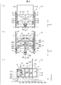
- FIG. 1 It is a perspective view showing composition of a wheelchair concerning an embodiment of the present invention.
- the structure of the wheelchair which concerns on embodiment of this invention when it will be in an unfolded state by a folding mechanism is shown, (a) is a front view, (b) is a top view, (c) is a side view. .
- the structure of the wheelchair which concerns on embodiment of this invention when it will be in a folding state by a folding mechanism is shown, (a) is a front view, (b) is a top view, (c) is a side view. .
- FIG. 1 is a perspective view showing the configuration of a wheelchair 10 according to the present embodiment.
- the wheelchair 10 includes a vehicle body frame 1, a folding mechanism 2 for folding the vehicle body frame 1, and a pair of drive wheels (also referred to as rear wheels) provided on the vehicle body frame 1. It is provided with 3 ⁇ 3 and one caster 4 (also referred to as front wheel) that assists the pair of drive wheels 3 ⁇ 3 forward.
- the wheelchair 10 is a three-wheeled configuration provided with one caster 4 for two drive wheels 3.
- the body frame 1 is provided with a back seat 71 and a seat 72 which are chair portions on which the user rides.
- the back seat 71 side of the wheelchair 10 is the rear side, and the rear side and the opposite side are the front side.
- the front side is the side on which the user in the wheelchair 10 is seated.
- the caster 4 side is made lower side with respect to the seat 72, and let the other side be upper side.
- the front-rear direction when defined as described above is taken as the X direction, the left and right direction as the Y direction, and the up and down direction as the Z direction. It can be said that the X direction is the traveling direction of the drive wheels 3 and 3.
- the wheelchair 10 is provided with a caster storage mechanism 5 (storage mechanism).
- the caster accommodation mechanism 5 has a mechanism for accommodating the caster 4 in the vehicle body frame 1 in conjunction with the folding operation by the folding mechanism 2.
- the wheelchair 10 is provided with brake and support mechanisms 6 and 6 (support mechanisms) on the left and right sides of the vehicle body frame 1, respectively.
- the brake / support mechanism 6, 6 has a mechanism for blocking the rotation of the drive wheels 3, 3 and for holding the position of the vehicle body frame 1 by the support member 63 coming into contact with the floor surface.
- the vehicle body frame 1 is configured such that left and right side frames 11 are connected by a folding mechanism 2.
- the side frame 11 has a rectangular frame formed by an upper horizontal frame 11A, a lower horizontal frame 11B, a front vertical frame 11C, and a back vertical frame 11D.
- upper frames 11E and 11E extending upward are provided on the upper horizontal frames 11A and 11A of the left and right side frames 11 and 11, respectively.
- support frames 11F and 11F for supporting the drive wheels 3 and 3 are provided in the rectangular frames of the left and right side frames 11 and 11, respectively.
- the support frames 11F and 11F have an H shape.
- the upper frames 11E and 11E may be provided with grip members for the caregiver pushing the wheelchair 10 to grip.
- the upper horizontal frames 11A and 11A may be provided with support portions for placing the user's arms and for standing and standing.
- the upper frames 11E and 11E are back frames, and a cloth back sheet 71 is stretched between the pair of upper frames 11E and 11E.
- the folding mechanism 2 folds the pair of side frames 11 in a direction in which they are brought close to each other.
- the folding mechanism 2 includes a cross frame 21 provided with a pair of cross rods 21A and 21A in an X shape, and two cross frames 21 and 21 are arranged in parallel in the front-rear direction of the vehicle body frame 1 .
- the lower horizontal frame 11B is provided with supports 21B.21B for supporting the lower end portions of the cross rods 21A.21A.
- the support pins 21B and 21B are provided with pivot pins 21C and 21C.
- the lower end portions of the cross rods 21A and 21A are rotatably supported on the YZ plane including the vertical direction (Z direction) and the horizontal direction (Y direction) via the pivot pins 21C and 21C.
- central portions of the X-shaped cross rods 21A and 21A are pivotally supported by a pivot shaft 22 extending in the front-rear direction. That is, the X-shaped cross rods 21A and 21A are rotatably supported in the vertical direction with the pivot shaft 22 at the center portion as an axis. Further, the two cross frames 21 disposed in parallel in the front-rear direction are connected to each other via a pivot shaft 22. The pivot shaft 22 also has a function of holding an interval between the two cross frames 21 in the front-rear direction. Further, upper end portions of the pair of cross rods 21A and 21A are connected by a pair of round bar-like connecting rods 23 and 23 disposed in the front-rear direction of the vehicle body frame 1.
- the wheelchair 10 can be folded in the left-right direction by the folding mechanism 2.
- the folding operation of the wheelchair 10 will be described.
- the cross frame 21 is pivoted so as to extend in the vertical direction around the pivot shaft 22 (the pivot shaft portion).
- the vehicle body frame 1 can be folded in the left-right direction of the wheelchair 10, and the wheelchair 10 is in a folded state.
- the cross frame 21 is pivoted around the pivot shaft 22 so as to extend in the left-right direction.
- the pivot shaft 22 is a vertically moving member that moves upward in conjunction with the folding operation of the folding mechanism 2.
- the pair of connecting rods 23 respectively abuts on the upper horizontal frames 11A and 11A of the side frames 11. Then, a cloth seat is stretched over the pair of connecting rods 23 and 23, whereby the seat sheet 72 of the wheelchair 10 is formed.
- Each of the pair of drive wheels 3 and 3 includes a wheel (not shown) and a rubber or resin tire (not shown) provided on the outer periphery of the wheel.
- Axle shafts 31 and 31 are provided at the centers of the drive wheels 3 and 3.
- the axle shafts 31, 31 are inserted into and supported by axle support holes (not shown) formed in the support frames 11F, 11F of the left and right side frames 11, 11, respectively.
- the pair of drive wheels 3 is rotatably supported by the vehicle body frame 1 by the axle shafts 31. Further, although not shown in FIG. 1, a hand rim used when the user moves the wheelchair 10 by himself is provided on the further outside of the pair of drive wheels 3.
- the brake and support mechanisms 6, 6 are provided on the upper horizontal frames 11A and 11A of the left and right side frames 11 and 11, respectively.
- the brake and support mechanism 6, 6 includes a bearing support plate 61, 61, operation levers 62, 62, support members 63, 63, link mechanisms 64, 64, and wheel pressing members 65, 65. .
- the link mechanisms 64 and 64 and the wheel pressing members 65 and 65 are mounted on the bearing support plate 61.
- the operation levers 62 and 62 are connected to the support members 63 and 63 and the wheel pressing members 65 and 65 via the link mechanisms 64 and 64, respectively.
- the link mechanisms 64, 64 transmit the force from the operation levers 62, 62 to both the support members 63, 63 and the wheel pressing members 65, 65.
- the wheel pressing members 65 and 65 abut against the drive wheels 3 and 3 to prevent the rotation of the drive wheels 3 and 3 by operating the control levers 62 forward. Do. Then, in conjunction with the rotation prevention of the drive wheels 3 and 3 by the wheel pressing members 65 and 65, the support members 63 come into contact with the floor surface, and the position of the vehicle body frame 1 is maintained.
- the configuration and operation of the link mechanisms 64 and 64 in the brake and support mechanisms 6 and 6 will be described later.
- the caster 4 is provided on the vehicle body frame 1 via the caster storage mechanism 5.
- the caster housing mechanism 5 is provided with a yoke 41 which rotatably supports the caster 4. As a result, the caster 4 pivots in the entire circumferential direction on the horizontal floor surface.
- the caster 4 is also configured to include a wheel (not shown) and a rubber or resin tire (not shown) provided on the outer periphery of the wheel.
- the caster storage mechanism 5 moves the caster 4 rearward in the X direction in conjunction with the folding operation by the folding mechanism 2. More specifically, the caster 4 is accommodated in the vehicle body frame 1 in conjunction with the approach of the pair of side frames 11.
- the configuration and operation of the caster storage mechanism 5 will be described in detail.
- FIG. 2 shows the configuration of the wheelchair 10 when the folding mechanism 2 is in the unfolded state
- FIG. 2 (a) is a front view
- FIG. 2 (b) is a top view
- c) is a side view
- 3 shows the configuration of the wheelchair 10 when it is in the folded state by the folding mechanism 2.
- FIG. 3 (a) is a front view
- FIG. 3 (b) is a top view
- c) is a side view.
- the caster housing mechanism 5 includes a rod-like arm 51 (holding member) for holding the caster 4, a pair of support arms 52 and 52 (first support arm), and a support arm 53. And (second support arm).
- the pair of support arms 52 is a member that connects the rod-like arm 51 to the pair of side frames 11.
- the support arm 53 is a member that connects the rod-like arm 51 and the pivot shaft 22 as an up and down moving member that moves upward in conjunction with the folding operation of the folding mechanism 2.
- the rod-like arm 51 has a shape extending in parallel in the front-rear direction, and is disposed so as to overlap the rotation shaft 22 in the Z direction. That is, the rotating shaft 22 extends in parallel to the X direction on the upper side of the rod-like arm 51.
- a support 51A for supporting the caster 4 is provided at the front end of the rod-like arm 51.
- the yoke 41 is provided on the support portion 51A.
- the pair of support arms 52, 52 is supported so that the end portions 52C, 52C (the holding member side end portions) can be pivoted relative to the rod-like arm 51. Then, they are arranged in line symmetry with the rod-like arm 51 as an axis, and form a V shape having the end 52C as a vertex.
- a plurality of pairs of support arms 52 are provided, and the end 52A, 52A (side frame side end) and the end 52C, 52C in each pair are in the X direction. Are arranged at predetermined intervals.
- connection portions of the rod-like arm 51 with the end portions 52C and 52C of the support arms 52 and 52 are provided at approximately the middle position and the rear end position in the length direction (front-rear direction) of the rod-like arm 51.
- the pair of support arms 52 are arranged in parallel in the front-rear direction.
- the pair of support arms 52 is a member that defines the position of the rod-like arm 51 in the left-right direction (Y direction). In the left-right direction, the rod-like arm 51 is disposed at a substantially central position between the side frames 11 facing each other. Further, the length direction of the rod-like arm 51 coincides with the front-rear direction (X direction). The pair of support arms 52 maintain the position of the rod-like arm 51 in the Y direction during operation of the wheelchair 10.
- Ends 52A and 52A (side frame side ends) opposite to the rod-like arm 51 in the pair of support arms 52 and 52 are supported by the side frames 11 and 11, respectively.
- the end portions 52A and 52A are provided with pivot pins 52B and 52B.
- the end portions 52A and 52A of the pair of support arms 52 and 52 are rotatably supported on the XY plane with respect to the side frames 11 and 11 via pivot pins 52B and 52B.
- pivot pins 52D, 52D are provided at the end portions 52C, 52C (end portions on the holding member side) of the support arms 52, 52 on the side of the rod-like arm 51.
- the ends 52C and 52C of the pair of support arms 52 and 52 are pivotally supported on the XY plane via pivot pins 52D and 52D.
- the pivot pins 52B and 52B provided on the side frames 11 and 11 side are disposed closer to the caster 4 than the pivot pins 52D and 52D provided on the rod-like arm 51 side.
- the end portions 52A and 52A are disposed on the front side in the X direction with respect to the end portions 52C and 52C.
- the support arm 53 is a member that defines the position of the rod-like arm 51 in the vertical direction (Z direction). In the vertical direction, the rod-like arm 51 is disposed such that the caster 4 supported by the support portion 51A is in contact with the floor surface. The support arm 53 holds this position. The support arm 53 holds the position of the rod-like arm 51 in the Z direction while the wheelchair 10 is in operation. As a result, the caster 4 is maintained in contact with the floor surface.
- a pivot pin 53 ⁇ / b> B is provided at an end 53 ⁇ / b> A (upper and lower moving member side end) of the support arm 53 opposite to the rod-like arm 51.
- the end 53A of the support arm 53 is rotatably supported on the XZ plane including the longitudinal direction (X direction) and the vertical direction (Z direction) with respect to the pivot shaft 22 via the pivot pin 53B.
- a pivot pin 53D is provided at an end 53C (end on the holding member side) of the support arm 53 on the side of the rod-like arm 51.
- the end 53C of the support arm 53 is rotatably supported on the XZ plane with respect to the rod-like arm 51 via a pivot pin 53D.
- the pivot pin 53D provided on the rod-like arm 51 side is disposed closer to the caster 4 than the pivot pin 53B provided on the pivot shaft 22 side. That is, the end portion 53C is disposed on the front side in the X direction with respect to the end portion 53A, and is close to the caster 4.
- the pair of support arms 52 are each end 52A
- the 52A is rotatably supported by the side frames 11 and 11, and the respective end portions 52C and 52C are rotatably supported by the rod-like arm 51.
- the end portions 52A and 52A are disposed forward of the end portions 52C and 52C.
- the support arm 53 is rotatably supported at the end 53C with respect to the rod-like arm 51 on the XZ plane (vertical surface) including both the rod-like arm 51 and the rotation shaft 22, and the end 53A is rotatably supported on the rotation shaft 22.
- the end 53C is disposed forward of the end 53A.
- the caster accommodation mechanism 5 accommodates the caster 4 in the vehicle body frame 1 in conjunction with the folding operation by the folding mechanism 2.
- the storage operation of the caster 4 in the vehicle body frame 1 by the caster storage mechanism 5 will be described.
- the pivot pins 52B and 52B provided on the side frames 11 and 11 side are closer to the caster 4 than the pivot pins 52D and 52D provided on the rod-like arm 51 side. Therefore, in the support arms 52, 52, the angle ⁇ 1 ⁇ ⁇ 1 formed between the support arms 52, 52 and the rod-like arm 51 becomes smaller while maintaining the V shape with the end 52C at the top by the folding operation. It works like that.
- the rod-like arm 51 supporting the caster 4 moves in the front-rear direction (X direction) so as to approach the side frames 11 by the movement of the support arms 52 during the folding operation. As a result, when the wheelchair 10 is in the folded state, the caster 4 is accommodated in the vehicle body frame 1.
- the rod-like arm 51 is held in the Z direction by the support arm 53 during the folding operation. Therefore, as the folding operation by the folding mechanism 2 proceeds, the distance between the pivot shaft 22 and the rod-like arm 51 in the Z direction increases. Then, the pivot pin 53B and the pivot pin 53D serve as a pivot and the support arm 53 is folded.
- the pivot pin 53D provided on the rod-like arm 51 side is closer to the caster 4 than the pivot pin 53B provided on the pivot shaft 22 side.
- the support arm 53 the folding operation, moves as the angle theta 2 between the support arm 53 and the rod-shaped arm 51 is increased.
- the rod-like arm 51 on which the caster 4 is supported moves in the front-rear direction (X direction) so as to approach the side frames 11 and 11 by the movement of the support arm 53 during the folding operation.
- the caster 4 is accommodated in the vehicle body frame 1.
- an angle ⁇ 1 ⁇ ⁇ between the support arms 52 ⁇ 52 and the rod-like arm 51 is formed by the pair of V-shaped support arms 52. It moves so that 1 becomes large.
- the support arm 53 is moved so that the angle theta 2 between the support arm 53 and the rod-shaped arm 51 is reduced.
- the rod-like arm 51 moves forward, and the caster 4 is disposed in front of the vehicle body frame 1.
- the lateral movement of the rod-like arm 51 is restricted by the pair of support arms 52, 52, and the vertical movement of the rod-like arm 51 is restricted by the support arm 53.
- the caster storage mechanism 5 can store the caster 4 in the vehicle body frame 1 in conjunction with the folding operation by the folding mechanism 2. Therefore, even in the three-wheeled wheelchair 10, the caster 4 can be efficiently stored in the vehicle body frame 1 by the folding operation, and the transportation performance of the wheelchair 10 is improved. Therefore, it is possible to realize a three-wheeled wheelchair that can be compactly folded and has a small installation space after folding.
- the caster accommodation mechanism 5 may include a lock portion that locks the rod-like arm 51 so as not to retract when the vehicle body frame 1 is changed from the folded state to the expanded state by the folding mechanism 2.
- the caster storage mechanism 5 is configured to include both of the pair of support arms 52 and 52 and the support arm 53.
- the caster accommodation mechanism 5 is not limited to the above configuration, and the caster 4 may be provided in the vehicle body frame 1 even if the caster accommodation mechanism 5 includes any one of the pair of support arms 52 and 52 and the support arm 53. It is possible to accommodate.
- the brake and support mechanism 6, 6 includes an operation lever 62 (switching mechanism) and two support members 63, 63 on the front side of the drive wheels 3 and 3 in the X direction.
- the support member 63 is a member that supports the position of the vehicle body frame 1 by coming into contact with the floor surface.
- the operating lever 62 is in a supported state in which the vehicle body frame 1 is supported by at least two supporting members 63 and a pair of driving wheels 3 and 3 with respect to the floor surface, and a separated state in which the supporting members 63 and 63 are separated from the floor surface And a member that switches between
- the wheelchair 10 which concerns on this embodiment will not be specifically limited if it is a structure which switches the said support state and the said separation state, The structure independent of the brake mechanism may be sufficient.
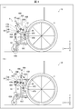
- FIG. 4 is a side view showing the operation of the brake and support mechanism 6.
- FIG. 4 (a) shows the state of the brake and support mechanism 6 when the rotation of the drive wheel 3 is blocked. b) shows the state of the brake and support mechanism 6 when the rotation prevention of the drive wheel 3 is released.
- the link mechanism 64 includes an L-shaped first actuation link member 66 and a second actuation link member 67.
- the L-shaped bending portion 66A of the first operation link member 66 is supported by the bearing support plate 61 via the pivot pin 66B.
- the first actuation link member 66 is pivotable in the XZ plane about a pivot pin 66B provided at the bending portion 66A.
- the operating lever 62 is connected to one end 66C of the first operating link member 66.
- a support member 63 is connected to the other end 66D of the first operation link member 66 via a pivot pin 63A.
- the support member 63 is pivotable about a pivot pin 63A provided at the end 66D. Further, a grounding portion 63 ⁇ / b> B is provided at an end of the support member 63 opposite to the first operation link member 66.
- the grounding portion 63B is made of a material such as rubber that has a relatively high frictional force with the floor surface.
- one end 65A of the wheel holding member 65 is rotatably supported by the bearing support plate 61 via the rotation pin 65B.
- the support position (position of the pivot pin 65B) of the wheel pressing member 65 in the bearing support plate 61 is located rearward of the support position (position of the pivot pin 66B) of the first operation link member 66.
- an abutting portion 65C that abuts on the drive wheel 3 is provided.
- the second actuation link member 67 is a member that connects the first actuation link member 66 and the wheel pressing member 65.
- One end 67A of the second actuation link member 67 is supported by the first actuation link member 66 via the pivot pin 67B.
- the second actuation link member 67 is pivotable relative to the first actuation link member 66 in the XZ plane with the pivot pin 67B as an axis.
- the connection position of the end 67A of the second operation link member 67 in the first operation link member 66 is a position between the end 66D to which the support member 63 is connected and the bending portion 66A.
- the connection position of the end 67A of the second actuating link member 67 in the first actuating link member 66 is the position between the end 66D and the bending portion 66A.
- connection position of the end 67A of the second actuation link member 67 is not limited to the configuration shown in FIGS. 4A and 4B, and the position between the end 66D and the bending portion 66A. If it is In particular, it is preferable that the second actuation link member 67 be connected between the end 66D and the bending portion 66A at a position closer to the end 66D than the center.
- connection position of the end portion 67C of the second operation link member 67 in the wheel pressing member 65 is a position closer to the contact portion 65C than the center of the wheel pressing member 65. It is preferable that the connection position of the end portion 67C of the second operation link member 67 be closer to the contact portion 65C of the wheel pressing member 65.
- the link mechanism 64 is in the support state where the support member 63 abuts on the floor when the wheel pressing member 65 abuts on the drive wheel 3, and when the wheel pressing member 65 is separated from the drive wheel 3. Act to move away from the floor surface.
- the operation of the brake and support mechanism 6 will be described based on (a) and (b) of FIG.
- the user rotates the operation lever 62 forward (counterclockwise in FIG. 4A).
- the first operation link member 66 is pivoted forward about the pivot pin 66B via the pivot pin 66B.
- the end 66D of the first operation link member 66 is rotated downward.
- the support member 63 is connected to the end 66D of the first actuation link member 66 via the pivot pin 63A.
- the support member 63 is pivotable about a pivot pin 63A provided at the end 66D. Therefore, with the rotation of the end 66D, the support member 63 moves vertically downward and contacts the floor surface via the grounding portion 63B.
- first actuation link member 66 is rotatably coupled to the second actuation link member 67 via the pivot pin 67B at a position between the end 66D and the bending portion 66A. .
- the second operation link member 67 is rotatably connected to the wheel pressing member 65 via the rotation pin 67D. Therefore, with the rotation of the first operation link member 66 by the rotation operation of the operation lever 62, the second operation link member 67 moves rearward, and a rear force is transmitted to the wheel pressing member 65.
- the force for turning the operating lever 62 forward is converted to a rear force by the link mechanism 64 and transmitted to the wheel pressing member 65.
- the wheel holding member 65 is rotatably supported at the end portion 65A by the bearing support plate 61 via the rotation pin 65B. Therefore, with the rotation of the first operation link member 66 due to the rotation operation of the operation lever 62, the wheel pressing member 65 has the contact portion 65C with the rotation pin 65B provided at the end 65A as an axis. It turns so as to approach the drive wheel 3. As a result, the rotation of the drive wheel 3 is blocked and locked by the contact of the contact portion 65C with the drive wheel 3.
- the user rotates the control lever 62 rearward (clockwise in (b) of FIG. 4).
- the first actuation link member 66 pivots rearward about the pivot pin 66B, and the end 66D of the first actuation link member 66 moves upward.
- the support member 63 moves vertically upward, and the ground contact portion 63B separates from the floor surface.
- the second actuation link member 67 moves forward as the first actuation link member 66 pivots upward.
- the wheel pressing member 65 connected to the second operation link member 67 rotates about the rotation pin 65B provided at the end 65A so that the contact portion 65C is separated from the drive wheel 3 Do.
- the lock of the drive wheel 3 by the wheel pressing member 65 is released.
- the link mechanism 64 operates in conjunction with the rotation prevention of the drive wheel 3 by the rotation operation of the operation lever 62.
- the two support members 63 contact the floor surface via the grounding portion 63B. Therefore, at the time of parking, the wheelchair 10 shown in FIG. 1 has three contact points 63B and 63B of the pair of support members 63 and 63 at three points of the pair of drive wheels 3 and 3 and the caster 4 with respect to the floor surface. It will be supported by 5 points added. Therefore, when the drive wheels 3 and 3 are locked and the user transfers, the ground contact area is increased and the stability of the vehicle body frame 1 is increased, so that the vehicle body frame 1 does not fall over. Thereby, the user can shift to the wheelchair 10 with ease.
- the link mechanism 64 interlocks with the lock release of the drive wheel 3 by the rotation operation of the operation lever 62, and the contact portion 63B of the two support members 63 is ground. Separates from the floor surface. Therefore, when traveling, the wheelchair 10 travels on three wheels of the pair of drive wheels 3 and 3 and the caster 4. Therefore, the wheelchair 10 according to the present embodiment can also realize the fine turn during traveling.
- the brake and support mechanisms 6 and 6 can realize the wheelchair 10 having both the merits of small turning during traveling and the stability at the time of wheel locking.
- the brake / support mechanism 6 interlocks with the locking operation of the drive wheel 3 by the pivoting operation of the operation lever 62 so that the support member 63 is a floor. It was configured to be in contact with the surface.
- the brake and support mechanism 6 is not limited to the configuration in which the operation of the support member 63 interlocks with the locking operation of the drive wheel 3 by the turning operation of the operation lever 62. It may be configured to include a first operation lever for operating the support member 63 and a second operation lever for operating the wheel pressing member 65. In such a configuration, the operation of the support member 63 by the first operation lever and the operation of the wheel pressing member 65 by the second operation lever are independent.
- the brake mechanism in the brake and support mechanism 6 is not limited to the configuration shown in (a) and (b) of FIG. 4 and may be a known mechanism.
- the brake mechanism in the brake / support mechanism 6 the drive wheel 3 is locked by the pivoting operation of the control lever 62 to the rear, and the lock of the drive wheel 3 is released by the pivoting operation of the control lever 62 to the front It may be a brake mechanism.
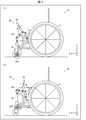
- FIG. 5 is a side view showing the configuration of a modification of the brake / support mechanism 6, and FIG. 5 (a) shows a state when the rotation of the drive wheel 3 is blocked, and FIG. 6 shows the state when the rotation prevention of the drive wheel 3 is released.
- a modified brake / support mechanism 6A has a point that the support member 63 includes a support caster 63C (supporting support wheel) (see FIG. It differs from the configuration shown in a) and (b).
- the two support members 63 are supported by the link mechanism 64 in conjunction with the rotation prevention of the drive wheel 3 by the rotation operation of the operation lever 62. Contact the floor through 63C. Even with such a configuration, when the drive wheel 3 is locked and the user transfers, the wheelchair 10 has two points on the floor surface at three points of the pair of drive wheels 3 and 3 and the caster 4 The supporting caster 63C of the supporting member 63 is supported at five points. Therefore, the contact area is increased, and the stability of the vehicle body frame 1 is increased, so that the vehicle body frame does not fall.
- the support casters 63C of the two support members 63 are linked by the link mechanism 64. It will be in the state separated from the floor surface. That is, the wheelchair 10 shown by (b) of FIG. 5 becomes a structure arrange
- the brake and support mechanism provided in the wheelchair 10 may have a configuration in which the brake and support mechanism 6 and the brake and support mechanism 6A are combined.
- the brake and support mechanism 6 shown in (a) and (b) of FIG. 4 may include a support caster 63C shown in (a) and (b) of FIG. In this case, the support caster 63C is separated from the floor regardless of traveling and locking of the drive wheel 3.
- the wheelchair 10 according to the present embodiment is not limited to the three-wheel configuration, and includes the vehicle body frame 1, and the vehicle body frame 1 is provided with a pair of drive wheels 3 and 3 and a caster 4 disposed in front thereof.
- the number of casters 4 is not particularly limited as long as the configuration is adopted. Therefore, if the brake / support mechanism 6/6 is configured to support the vehicle body frame by the at least two support members 63/63 and the pair of drive wheels 3/3 with respect to the floor surface in the support state, Well, depending on the number of castors 4, the support point to the floor also differs.
- the wheelchair which concerns on one Embodiment of this invention is a advancing direction with respect to a pair of side frame, the driving wheel provided one each in the pair of side frames, and the pair of driving wheels.
- the storage mechanism is provided to move the
- the storage mechanism is provided to move the auxiliary wheel rearward in the advancing direction in conjunction with the folding operation by the folding mechanism, so that it can be folded compactly and the installation space after folding is A small wheelchair can be realized.
- the storage mechanism includes a pair of first support arms that respectively connect the holding member for holding the auxiliary wheel and the pair of side frames;
- each side frame side end is rotatably supported to the side frame, and each holding member side end is rotatably supported to the holding member,
- the side frame side end may be disposed on the front side in the traveling direction with respect to the holding member side end.
- the side frame side end portions of the pair of first support arms are rotatably supported with respect to the side frame, and the respective holding member side end portions are the holding side
- the side frame side end portion is rotatably supported by the member, and the side frame side end portion is disposed on the front side in the advancing direction with respect to the support member side end portion.
- the holding member holding the auxiliary wheel is retracted. Therefore, according to the above configuration, it is possible to realize a wheelchair that can be folded compactly and has a small installation space after folding.
- the storage mechanism connects the holding member for supporting the auxiliary wheel and the vertical movement member which moves upward in conjunction with the folding operation by the folding mechanism.
- the second support arm has a vertical movement member side end rotatably supported by the vertical movement member, and a holding member side end rotates relative to the holding member.
- the holding member side end may be movably supported, and may be disposed on the front side in the traveling direction with respect to the vertical movement member side end.
- the second support arm has the vertically movable member side end portion rotatably supported by the vertically movable member, and the holding member side end portion pivoted relative to the holding member.
- the holding member side end portion is supported on the front side in the traveling direction with respect to the vertical movement member side end portion, so that the holding member side end portion is moved upward in the vertical movement member in conjunction with the folding operation by the folding mechanism. With the movement, the holding member provided with the auxiliary wheel retracts. Therefore, according to the above configuration, it is possible to realize a wheelchair that can be folded compactly and has a small installation space after folding.
- the holding member has a shape extending in parallel with the traveling direction, and a plurality of pairs of the first support arms are provided, and the side frame side in each pair It is preferable that the end portion and the support member side end portion be arranged side by side at a predetermined interval in the traveling direction.
- connection structure between the side frame and the holding member can be made robust. Therefore, a rigid wheelchair can be provided.
- the folding mechanism includes a cross frame having a pair of cross rods which connect the pair of side frames and intersect each other, and the vertical movement member.
- the vertically moving member is a pivot shaft portion extending in parallel in the advancing direction on the upper side of the holding member and pivotally supporting the crossing portion of the pair of cross rods.
Landscapes
- Health & Medical Sciences (AREA)
- Life Sciences & Earth Sciences (AREA)
- Animal Behavior & Ethology (AREA)
- General Health & Medical Sciences (AREA)
- Public Health (AREA)
- Veterinary Medicine (AREA)
- Handcart (AREA)
Abstract
コンパクトに折り畳むことができ、かつ折り畳み後の設置スペースが小さい車椅子を実現することを目的として、本発明の車椅子(10)は、折り畳み機構(2)による折り畳み動作に連動してキャスタ(4)を進行方向後ろ側に移動させるキャスタ収納機構(5)を備えている。
Description
本発明は、車椅子に関する。
介護用または身体が不自由な人が利用する車椅子は、車体に前輪と後輪とが設けられ、この車体には背部及び座部が形成されている。
例えば特許文献1には、前輪が着脱可能な折り畳み式の車椅子が開示されている。
特許文献1に記載の折り畳み式の車椅子は、車体に2つの前輪(補助輪)と2つの駆動輪を備えた4輪構成である。
走行中の小回りの観点では、車椅子は、2つの主車輪に対して1つの前輪(補助輪)を備えた3輪構成であることが好ましい。さらに、運搬の容易性の観点から、3輪構成の車椅子は折り畳み式であることが好ましい。
3輪構成の折り畳み式車椅子を実現するために、特許文献1に記載の技術を適用した場合、折り畳み後と折り畳み前とで前輪の位置が変化しないため、折り畳み後の車椅子を設置するスペースが大きいという問題がある。
本発明の一態様は、コンパクトに折り畳むことができ、かつ折り畳み後の設置スペースが小さい車椅子を実現することを目的とする。
上記の課題を解決するために、本発明の一態様に係る車椅子は、1対のサイドフレームと、前記1対のサイドフレームにそれぞれ1つずつ設けられる駆動輪と、前記1対の駆動輪よりも進行方向前側に配置される補助輪とを備えた車椅子であって、前記1対のサイドフレーム同士を近づける方向に折り畳む折り畳み機構と、前記折り畳み機構による折り畳み動作に連動して前記補助輪を進行方向後ろ側に移動させる収納機構を備えたことを特徴としている。
本発明の一態様によれば、コンパクトに折り畳むことができ、かつ折り畳み後の設置スペースが小さい車椅子を実現できるという効果を奏する。
以下、本発明の一実施形態について、詳細に説明する。図1は、本実施形態に係る車椅子10の構成を示す斜視図である。
図1に示されるように、本実施形態に係る車椅子10は、車体フレーム1と、車体フレーム1を折り畳む折り畳み機構2と、車体フレーム1に設けられた1対の駆動輪(後輪ともいう)3・3と、1対の駆動輪3・3を前方で補助する1つのキャスタ4(前輪ともいう)と、を備えている。車椅子10は、2つの駆動輪3・3に対し1つのキャスタ4を備えた3輪式の構成である。車体フレーム1には、使用者が搭乗する椅子部分である背シート71及び座シート72が設けられている。ここで、車椅子10の背シート71側を後側とし、後側と反対側を前側とする。前側は、車椅子10における使用者が搭乗する側であるともいえる。また、座シート72に対してキャスタ4側を下側とし、その反対側を上側とする。また、上記のように規定した場合の前後方向をX方向とし、左右方向をY方向とし、上下方向をZ方向とする。X方向は、駆動輪3・3の進行方向であるともいえる。
また、車椅子10は、キャスタ収納機構5(収納機構)が設けられている。このキャスタ収納機構5は、折り畳み機構2による折り畳み動作に連動してキャスタ4を車体フレーム1内に収納する機構を有している。
また、車椅子10は、車体フレーム1の左側及び右側にそれぞれ、ブレーキ・支持機構6・6(支持機構)が設けられている。このブレーキ・支持機構6・6は、駆動輪3・3の回転を阻止するとともに、支持部材63が床面と接触することにより車体フレーム1の位置を保持する機構を有している。
車体フレーム1は、左右のサイドフレーム11・11が折り畳み機構2により連結された構成となっている。サイドフレーム11は、上側水平フレーム11A、下側水平フレーム11B、前側垂直フレーム11C、及び背側垂直フレーム11Dにより形成された四角形状フレームを有する。また、左右のサイドフレーム11・11の上側水平フレーム11A・11Aにはそれぞれ、上方に延びた上方フレーム11E・11Eが設けられている。また、左右のサイドフレーム11・11それぞれの四角形状フレーム内には、駆動輪3・3を支持するための支持フレーム11F・11Fは設けられている。この支持フレーム11F・11Fは、H形状を有している。なお、車体フレーム1・1には、例えば、上方フレーム11E・11Eに、車椅子10を押す介護者が握るためのグリップ部材が設けられていてもよい。また、上側水平フレーム11A・11Aには、使用者の腕を置いたり、立ち座りをしたりするときのサポート部分が設けられていてもよい。また、上方フレーム11E・11Eは背フレームになっており、1対の上方フレーム11E・11E同士の間に布製の背シート71が架け渡されている。
折り畳み機構2は、1対のサイドフレーム11・11同士を近づける方向に折り畳む。折り畳み機構2は、X形状をした1対のクロス棒21A・21Aを備えたクロスフレーム21を備え、2つのクロスフレーム21・21が車体フレーム1の前後方向に並列配置された構成となっている。また、左右のサイドフレーム11・11を構成する部材のうち下側水平フレーム11Bには、それぞれのクロス棒21A・21Aの下端部を支持するための支持具21B・21Bが設けられている。支持具21B・21Bには、回動ピン21C・21Cが設けられている。それぞれのクロス棒21A・21Aの下端部は、回動ピン21C・21Cを介して、上下方向(Z方向)及び左右方向(Y方向)を含むYZ面上に回動可能に支持されている。
また、X形状のクロス棒21A・21Aの中央部は、前後方向に延びる回動シャフト22によって軸支されている。すなわち、X形状のクロス棒21A・21Aは、中央部の回動シャフト22を軸として、上下方向に回転可能に支持されている。また、前後方向に並列配置された2つのクロスフレーム21・21同士は、回動シャフト22を介して連結している。回動シャフト22は、2つのクロスフレーム21・21同士の前後方向の間隔を保持する機能も有する。また、1対のクロス棒21A・21Aの上端部は、車体フレーム1の前後方向に配置された1対の丸棒状の連結棒23・23によって連結される。
車椅子10は、折り畳み機構2により、左右方向に折り畳むことが可能となる。車椅子10の折り畳み動作について、説明する。まず、クロスフレーム21を回動シャフト22(回動軸部)の周りに上下方向に延びるように回動させる。これによって、車体フレーム1を車椅子10の左右方向に折り畳むことができ、車椅子10は、折り畳み状態となる。また、クロスフレーム21を回動シャフト22の周りに左右方向に延びるように回動させる。これによって、車体フレーム1を車椅子10の左右方向に広げることができ、車椅子10は、展開状態となる。回動シャフト22は、折り畳み機構2の折り畳み動作に連動して上方向へ移動する上下移動部材である。
車椅子10では、車体フレーム1を広げきったとき、1対の連結棒23・23はそれぞれ、サイドフレーム11の上側水平フレーム11A・11Aに当接する。そして、1対の連結棒23・23には布製のシートを架け渡され、これにより車椅子10の座シート72が形成される。
1対の駆動輪3・3はそれぞれ、ホイール(不図示)、及びホイールの外周に設けられたゴム製または樹脂製のタイヤ(不図示)を備えた構成となっている。駆動輪3・3の中心には車軸シャフト31・31が設けられている。そして、車軸シャフト31・31はそれぞれ、左右のサイドフレーム11・11の支持フレーム11F・11Fに形成された車軸支持穴(図示せず)に挿通して支持されている。1対の駆動輪3・3は、車軸シャフト31・31により、車体フレーム1に回動可能に支持される。また、図1には示されていないが、1対の駆動輪3・3の更に外側には、使用者が自分で車椅子10を動かすときに使用されるハンドリムが設けられる。
また、ブレーキ・支持機構6・6はそれぞれ、左右のサイドフレーム11・11における上側水平フレーム11A・11Aに設けられている。ブレーキ・支持機構6・6は、軸受け支持板61・61と、操作レバー62・62と、支持部材63・63と、リンク機構64・64と、車輪押え部材65・65と、を備えている。軸受け支持板61には、リンク機構64・64及び車輪押え部材65・65が搭載されている。また、操作レバー62・62は、リンク機構64・64を介して、支持部材63・63及び車輪押え部材65・65それぞれと連結している。リンク機構64・64は、操作レバー62・62による力を支持部材63・63及び車輪押え部材65・65の両方に伝達する。リンク機構64・64の作用により、車椅子10では、操作レバー62・62を前方へ操作させることによって、車輪押え部材65・65が駆動輪3・3に当接し駆動輪3・3の回転を阻止する。そして、この車輪押え部材65・65による駆動輪3・3の回転阻止と連動して、支持部材63・63が床面に接地し、車体フレーム1の位置が保持される。ブレーキ・支持機構6・6におけるリンク機構64・64の構成や作用については、後述する。
また、キャスタ4は、キャスタ収納機構5を介して、車体フレーム1に設けられている。キャスタ収納機構5には、キャスタ4を回転可能に支持するヨーク41が設けられている。これにより、キャスタ4は、水平な床面上にて全周方向に旋回する。なお、キャスタ4も、ホイール(不図示)、及びホイールの外周に設けられたゴム製または樹脂製のタイヤ(不図示)を備えた構成となっている。
(キャスタ収納機構5)
本実施形態に係る車椅子10の特徴的構成の1つは、キャスタ収納機構5を備えた点である。キャスタ収納機構5は、折り畳み機構2による折り畳み動作に連動してキャスタ4をX方向後ろ側に移動させる。より具体的には、1対のサイドフレーム11・11同士の接近に連動してキャスタ4を車体フレーム1内に収容する。以下、キャスタ収納機構5の構成及び動作について、詳述する。
本実施形態に係る車椅子10の特徴的構成の1つは、キャスタ収納機構5を備えた点である。キャスタ収納機構5は、折り畳み機構2による折り畳み動作に連動してキャスタ4をX方向後ろ側に移動させる。より具体的には、1対のサイドフレーム11・11同士の接近に連動してキャスタ4を車体フレーム1内に収容する。以下、キャスタ収納機構5の構成及び動作について、詳述する。
図2は、折り畳み機構2により展開状態となったときの車椅子10の構成を示し、図2の(a)は正面図であり、図2の(b)は上面図であり、図2の(c)は側面図である。図3は、折り畳み機構2により折り畳み状態となったときの車椅子10の構成を示し、図3の(a)は正面図であり、図3の(b)は上面図であり、図3の(c)は側面図である。
図1~図3に示されるように、キャスタ収納機構5は、キャスタ4を保持する棒状アーム51(保持部材)と、1対の支持アーム52・52(第1支持アーム)と、支持アーム53(第2支持アーム)と、を備えている。1対の支持アーム52・52は、棒状アーム51と1対のサイドフレーム11・11とをそれぞれ接続する部材である。支持アーム53は、棒状アーム51と、折り畳み機構2の折り畳み動作に連動して上方向に移動する上下移動部材としての回動シャフト22とを接続する部材である。
棒状アーム51は、前後方向に平行に延びた形状となっており、Z方向において回動シャフト22と重なるように配置されている。すなわち、回動シャフト22は、棒状アーム51の上側にて、X方向に平行に延びている。棒状アーム51の前端部には、キャスタ4を支持する支持部51Aが設けられている。ヨーク41は、この支持部51Aに設けられている。
また、上側から見て、1対の支持アーム52・52は、それぞれの端部52C・52C(保持部材側端部)が棒状アーム51に対し回動可能になるように支持されている。そして、棒状アーム51を軸として線対称になるように配置され、端部52Cを頂点とするV字形状を形成する。図1~図3に示された構成では、支持アーム52・52の対が複数設けられ、それぞれの対における端部52A・52A(サイドフレーム側端部)および端部52C・52Cが、X方向に所定の間隔で並んで配置される。棒状アーム51における支持アーム52・52の端部52C・52Cとの連結部は、棒状アーム51の長さ方向(前後方向)におけるほぼ中間位置、及び後端位置に設けられる。1対の支持アーム52・52は、前後方向に並列して配置されている。このように支持アーム52・52の対が複数設けられるので、サイドフレーム11・11と棒状アーム51との接続構造を頑強にすることができる。よって、剛性の高い車椅子10を提供することができる。
1対の支持アーム52・52は、左右方向(Y方向)において棒状アーム51の位置を規定する部材である。左右方向において、棒状アーム51は、互いに対向するサイドフレーム11・11間の略中央の位置に配置されている。また、棒状アーム51の長さ方向は、前後方向(X方向)に一致している。1対の支持アーム52・52は、車椅子10の動作中、Y方向における棒状アーム51の位置を保持する。
1対の支持アーム52・52における棒状アーム51と反対側の端部52A・52A(サイドフレーム側端部)は、サイドフレーム11・11に支持されている。端部52A・52Aには、回動ピン52B・52Bが設けられている。1対の支持アーム52・52の端部52A・52Aは、回動ピン52B・52Bを介して、サイドフレーム11・11対しXY面上で回動可能に支持されている。また、支持アーム52・52における棒状アーム51側の端部52C・52C(保持部材側端部)には、回動ピン52D・52Dが設けられている。1対の支持アーム52・52の端部52C・52Cは、回動ピン52D・52Dを介して、XY面上に回動可能に支持されている。キャスタ収納機構5では、サイドフレーム11・11側に設けられた回動ピン52B・52Bは、棒状アーム51側に設けられた回動ピン52D・52Dよりもキャスタ4に近くなるように配置されている。すなわち、端部52A・52Aは、端部52C・52CよりもX方向前側に配置されている。
また、支持アーム53は、上下方向(Z方向)において、棒状アーム51の位置を規定する部材である。上下方向において、棒状アーム51は、支持部51Aにて支持されたキャスタ4が床面に接触するように配置されている。支持アーム53により、この位置が保持される。支持アーム53は、車椅子10の動作中、Z方向における棒状アーム51の位置を保持する。これにより、キャスタ4が床面に接触した状態が維持される。
支持アーム53における棒状アーム51と反対側の端部53A(上下移動部材側端部)には、回動ピン53Bが設けられている。支持アーム53の端部53Aは、回動ピン53Bを介して、回動シャフト22に対して、前後方向(X方向)及び上下方向(Z方向)を含むXZ面上で回動可能に支持されている。また、支持アーム53における棒状アーム51側の端部53C(保持部材側端部)には、回動ピン53Dが設けられている。支持アーム53の端部53Cは、回動ピン53Dを介して、棒状アーム51に対しXZ面上に回動可能に支持されている。キャスタ収納機構5では、棒状アーム51側に設けられた回動ピン53Dは、回動シャフト22側に設けられた回動ピン53Bよりもキャスタ4に近くなるように配置されている。すなわち、端部53Cは、端部53AよりもX方向前側に配され、キャスタ4に近い。
以上のように、キャスタ収納機構5では、棒状アーム51及び1対の支持アーム52・52の両方を含むXY面(水平面)上で、1対の支持アーム52・52は、それぞれの端部52A・52Aがサイドフレーム11・11に対し回動可能に支持されていると共に、それぞれの端部52C・52Cが棒状アーム51に対し回動可能に支持されている。そして、端部52A・52Aは、端部52C・52Cよりも前方に配されている。また、支持アーム53は、棒状アーム51及び回動シャフト22の両方を含むXZ面(垂直面)上で、端部53Cが棒状アーム51に対して回動可能に支持されていると共に、端部53Aが回動シャフト22に対して回動可能に支持されている。そして、端部53Cは、端部53Aよりも前方に配されている。
このようなキャスタ収納機構5により、キャスタ4は、折り畳み機構2による折り畳み動作に連動して車体フレーム1内に収納される。以下、キャスタ収納機構5によるキャスタ4の車体フレーム1内の収納動作について、説明する。
図2の(a)~(c)及び図3の(a)~(c)に示されるように、折り畳み機構2による折り畳み動作が進むに従い、サイドフレーム11・11間の距離が小さくなるとともに、回動シャフト22が上方へ移動する。一方、棒状アーム51は、折り畳み動作中、1対の支持アーム52・52によりY方向における位置が保持されている。このため、折り畳み機構2による折り畳み動作が進むに従い、Y方向におけるサイドフレーム11・11と棒状アーム51との距離は小さくなる。そして、回動ピン52B・52Bと回動ピン52D・52Dとが回動軸となって支持アーム52・52が折り畳まれる。
ここで、支持アーム52・52において、サイドフレーム11・11側に設けられた回動ピン52B・52Bは、棒状アーム51側に設けられた回動ピン52D・52Dよりもキャスタ4に近い。それゆえ、支持アーム52・52は、折り畳み動作により、端部52Cを頂点とするV字形状を維持しつつ、支持アーム52・52と棒状アーム51とのなす角度θ1・θ1が小さくなるように動く。このとき、キャスタ4が支持された棒状アーム51は、折り畳み動作中、支持アーム52・52の動きにより、サイドフレーム11・11へ近づくように前後方向(X方向)へ移動する。その結果、車椅子10の折り畳み状態では、キャスタ4が車体フレーム1内に収容される。
また、棒状アーム51は、折り畳み動作中、支持アーム53によりZ方向における位置が保持されている。このため、折り畳み機構2による折り畳み動作が進むに従い、Z方向における回動シャフト22と棒状アーム51との距離は大きくなる。そして、回動ピン53Bと回動ピン53Dとが回動軸となって支持アーム53が折り畳まれる。
ここで、支持アーム53において、棒状アーム51側に設けられた回動ピン53Dは、回動シャフト22側に設けられた回動ピン53Bよりもキャスタ4に近い。それゆえ、支持アーム53は、折り畳み動作により、支持アーム53と棒状アーム51とのなす角度θ2が大きくなるように動く。このとき、キャスタ4が支持された棒状アーム51は、折り畳み動作中、支持アーム53の動きにより、サイドフレーム11・11へ近づくように前後方向(X方向)へ移動する。その結果、車椅子10の折り畳み状態では、キャスタ4が車体フレーム1内に収容される。
また、折り畳み機構2により車体フレーム1を折り畳み状態から展開状態にしたとき、V字形状の1対の支持アーム52・52は、支持アーム52・52と棒状アーム51とのなす角度θ1・θ1が大きくなるように動く。また、支持アーム53は、支持アーム53と棒状アーム51とのなす角度θ2が小さくなるように動く。この支持アーム52・52及び支持アーム53の動きに伴い、棒状アーム51は、前方へ移動し、キャスタ4が車体フレーム1の前方に配置される。棒状アーム51が前方へ移動する間は、1対の支持アーム52・52によって棒状アーム51の左右方向の動きが規制され、支持アーム53によって棒状アーム51の上下方向の動きが規制される。
このように、車椅子10では、キャスタ収納機構5により、折り畳み機構2による折り畳み動作に連動してキャスタ4を車体フレーム1内に収納することが可能となる。それゆえ、3輪式の車椅子10であっても、折り畳み動作によりキャスタ4を効率的に車体フレーム1内に収納することができ、車椅子10の運搬性能が向上する。したがって、コンパクトに折り畳むことができ、かつ折り畳み後の設置スペースが小さい3輪構成の車椅子を実現することができる。
なお、キャスタ収納機構5は、折り畳み機構2により車体フレーム1を折り畳み状態から展開状態にしたときに棒状アーム51が後退しないようにロックするロック部を備えていてもよい。
また、上記の構成例では、キャスタ収納機構5は、車体フレーム1内にキャスタ4を収容するために、1対の支持アーム52・52及び支持アーム53の両方を備えた構成であった。しかし、キャスタ収納機構5は、上記の構成に限定されず、1対の支持アーム52・52、及び支持アーム53の何れか1つを備えた構成であっても、車体フレーム1内にキャスタ4を収容することが可能である。
(ブレーキ・支持機構6・6)
本実施形態に係る車椅子10の他の特徴的構成は、ブレーキ・支持機構6・6を備えた点である。ブレーキ・支持機構6・6は、操作レバー62(切替機構)と、駆動輪3・3のX方向前側に2つの支持部材63・63と、を備えている。支持部材63は、床面と接触することにより車体フレーム1の位置を支持する部材である。操作レバー62は、床面に対し少なくとも2つの支持部材63・63と1対の駆動輪3・3により車体フレーム1を支持する支持状態と、支持部材63・63が床面から離間した離間状態とを切り替える部材である。
本実施形態に係る車椅子10の他の特徴的構成は、ブレーキ・支持機構6・6を備えた点である。ブレーキ・支持機構6・6は、操作レバー62(切替機構)と、駆動輪3・3のX方向前側に2つの支持部材63・63と、を備えている。支持部材63は、床面と接触することにより車体フレーム1の位置を支持する部材である。操作レバー62は、床面に対し少なくとも2つの支持部材63・63と1対の駆動輪3・3により車体フレーム1を支持する支持状態と、支持部材63・63が床面から離間した離間状態とを切り替える部材である。
以下では、操作レバーの操作により、駆動輪3・3の回転を阻止するブレーキ機構と連動して前記支持状態と前記離間状態とを切り替えるブレーキ・支持機構6・6の動作について、説明する。なお、本実施形態に係る車椅子10は、前記支持状態と前記離間状態とを切り替える構成であれば特に限定されず、ブレーキ機構と独立した構成であってもよい。
図4は、ブレーキ・支持機構6の動作を示す側面図であり、図4の(a)は、駆動輪3の回転を阻止したときのブレーキ・支持機構6の状態を示し、図4の(b)は、駆動輪3の回転阻止を解除したときのブレーキ・支持機構6の状態を示す。
図4の(a)及び(b)に示されるように、リンク機構64は、L字形状の第1の作動リンク部材66と、第2の作動リンク部材67と、を備えている。第1の作動リンク部材66は、L字形状の屈曲部66Aが、回動ピン66Bを介して軸受け支持板61に支持されている。第1の作動リンク部材66は、屈曲部66Aに設けられた回動ピン66Bを軸としてXZ平面で回動可能になっている。また、第1の作動リンク部材66の一方の端部66Cには操作レバー62が連結している。そして、第1の作動リンク部材66の他方の端部66Dには、支持部材63が、回動ピン63Aを介して連結している。このため、支持部材63は、端部66Dに設けられた回動ピン63Aを軸として回動可能になっている。また、支持部材63における第1の作動リンク部材66と反対側の端部には、接地部63Bが設けられている。接地部63Bは、ゴムなどの床面との摩擦力が比較的高い材料により構成されている。
また、車輪押え部材65の一方の端部65Aは、回動ピン65Bを介して軸受け支持板61に回動可能に支持されている。軸受け支持板61における車輪押え部材65の支持位置(回動ピン65Bの位置)は、第1の作動リンク部材66の支持位置(回動ピン66Bの位置)よりも後方に位置している。車輪押え部材65の他方の端部には、駆動輪3と当接する当接部65Cが設けられている。
第2の作動リンク部材67は、第1の作動リンク部材66と車輪押え部材65とを連結する部材である。
第2の作動リンク部材67の一方の端部67Aは、回動ピン67Bを介して、第1の作動リンク部材66に支持されている。第2の作動リンク部材67は、回動ピン67Bを軸として、第1の作動リンク部材66に対してXZ平面で回動可能になっている。第1の作動リンク部材66における第2の作動リンク部材67の端部67Aの連結位置は、支持部材63が連結している端部66Dと屈曲部66Aとの間の位置である。図4の(a)及び(b)に示された構成では、第1の作動リンク部材66における第2の作動リンク部材67の端部67Aの連結位置は、端部66Dと屈曲部66Aとの間の略中央位置である。しかし、第2の作動リンク部材67の端部67Aの連結位置は、図4の(a)及び(b)に示された構成に限定されず、端部66Dと屈曲部66Aとの間の位置であればよい。特に、第2の作動リンク部材67は、端部66Dと屈曲部66Aとの間において、中央よりも端部66Dに近い位置に連結していることが好ましい。
また、第2の作動リンク部材67の他方の端部67Cは、回動ピン67Dを介して、車輪押え部材65に支持されている。第2の作動リンク部材67は、回動ピン67Dを軸として、車輪押え部材65に対してXZ平面で回動可能になっている。車輪押え部材65における第2の作動リンク部材67の端部67Cの連結位置は、車輪押え部材65の中央よりも当接部65Cに近い位置である。第2の作動リンク部材67の端部67Cの連結位置は、車輪押え部材65の当接部65Cに近ければ近いほど好ましい。
リンク機構64は、車輪押え部材65が駆動輪3に当接したときに支持部材63が床面に当接した前記支持状態になり、車輪押え部材65が駆動輪3から離間したときには支持部材63が床面から離間した離間状態になる動作をする。ブレーキ・支持機構6の動作について、図4の(a)及び(b)に基づいて説明する。
図4の(a)に示されるように、ブレーキ・支持機構6の操作レバー62が前方へ移動した状態では、支持部材63の接地部63Bが床面に接地するとともに、車輪押え部材65の接地部63Bが駆動輪3に当接している。この状態では、駆動輪3の回転が阻止されているとともに、車椅子10は、床面に対して、2つの駆動輪3・3、キャスタ4、及び2つの支持部材63・63との5点で支持されている。
車椅子10を駐車する場合、使用者は操作レバー62を前方へ(図4の(a)において反時計周りに)回動操作する。このとき、回動ピン66Bを介して、第1の作動リンク部材66が回動ピン66Bを軸として前方へ回動する。そして、この回動により、第1の作動リンク部材66の端部66Dは下方へ回動する。ここで、第1の作動リンク部材66の端部66Dには、支持部材63が、回動ピン63Aを介して連結している。そして、支持部材63は、端部66Dに設けられた回動ピン63Aを軸として回動可能になっている。それゆえ、端部66Dの回動に伴い、支持部材63は、鉛直下方向へ移動し、接地部63Bを介して床面に接触する。
また、第1の作動リンク部材66は、端部66Dと屈曲部66Aとの間の位置にて、回動ピン67Bを介して、第2の作動リンク部材67と回動可能に連結している。そして、第2の作動リンク部材67は、回動ピン67Dを介して、車輪押え部材65と回動可能に連結している。それゆえ、操作レバー62の回動操作による第1の作動リンク部材66の回動に伴い第2の作動リンク部材67が後方へ移動し、車輪押え部材65に対し後方の力が伝達される。このようにブレーキ・支持機構6では、操作レバー62を前方へ回動操作する力が、リンク機構64により後方の力に変換されて車輪押え部材65へ伝達される。ここで、車輪押え部材65は、端部65Aにて、回動ピン65Bを介して軸受け支持板61に回動可能に支持されている。それゆえ、操作レバー62の回動操作による第1の作動リンク部材66の回動に伴い、車輪押え部材65は、端部65Aに設けられた回動ピン65Bを軸として、当接部65Cが駆動輪3に近づくように回動する。その結果、当接部65Cの駆動輪3への当接により、駆動輪3の回転が阻止されロックされる。
駆動輪3のロックを解除するためには、使用者は、操作レバー62を後方へ(図4の(b)において時計周りに)回動操作する。これにより、第1の作動リンク部材66が回動ピン66Bを軸として後方へ回動し、第1の作動リンク部材66の端部66Dは上方へ移動する。そして、端部66Dの移動に伴い、支持部材63は、鉛直上方向へ移動し、接地部63Bが床面から離間する。また第2の作動リンク部材67は、第1の作動リンク部材66の上方への回動に伴い、前方へ移動する。そして、第2の作動リンク部材67に連結している車輪押え部材65は、端部65Aに設けられた回動ピン65Bを軸として、当接部65Cが駆動輪3から離間するように回動する。その結果、駆動輪3の車輪押え部材65によるロックが解除される。
このように、本実施形態に係る車椅子10によれば、使用者が車椅子10を駐車するとき、操作レバー62の回動操作による駆動輪3の回転阻止と連動して、リンク機構64により、2つの支持部材63が接地部63Bを介して床面に接触する。それゆえ、駐車時、図1に示す車椅子10は、床面に対して、1対の駆動輪3・3及びキャスタ4の3点に、1対の支持部材63・63の接地部63B・63Bを加えた5点で支持されることになる。したがって、駆動輪3・3をロックして使用者が乗り移る際、接地面積が増え、車体フレーム1の安定性が増すため、車体フレーム1が転倒することはない。これにより、使用者は安心して車椅子10に乗り移ることができる。
また、使用者が駆動輪3・3のロックを解除するときには、操作レバー62の回動操作による駆動輪3のロック解除と連動して、リンク機構64により、2つの支持部材63の接地部63Bが床面から離間する。それゆえ、走行時、車椅子10は、1対の駆動輪3・3及びキャスタ4の3輪にて走行することになる。したがって、本実施形態に係る車椅子10は、走行時の小回りの良さも実現できる。
以上のことから、本実施形態によれば、ブレーキ・支持機構6・6により、走行時の小回りの良さと車輪ロック時の安定性との両方を兼ね備えた車椅子10を実現できる。
なお、図4の(a)及び(b)に示された構成では、ブレーキ・支持機構6は、操作レバー62の回動操作による駆動輪3のロック動作と連動して、支持部材63が床面と接触する構成であった。しかし、ブレーキ・支持機構6は、支持部材63の動作が操作レバー62の回動操作による駆動輪3のロック動作と連動する構成に限定されるものではない。支持部材63を操作する第1の操作レバーと、車輪押え部材65を操作する第2の操作レバーとを備えた構成であってもよい。このような構成では、第1の操作レバーによる支持部材63の動作と第2の操作レバーによる車輪押え部材65の動作とが独立している。
また、図4の(a)及び(b)に示された構成では、ブレーキ・支持機構6は、操作レバー62の前方への回動操作により駆動輪3がロックされ、操作レバー62の後方への回動操作により駆動輪3のロックが解除されるブレーキ機構であった。しかし、ブレーキ・支持機構6におけるブレーキ機構は、図4の(a)及び(b)に示された構成に限定されず、公知の機構であり得る。例えば、ブレーキ・支持機構6におけるブレーキ機構は、操作レバー62の後方への回動操作により駆動輪3がロックされ、操作レバー62の前方への回動操作により駆動輪3のロックが解除されるブレーキ機構であってもよい。
図5は、ブレーキ・支持機構6の変形例の構成を示す側面図であり、図5の(a)は、駆動輪3の回転を阻止したときの状態を示し、図5の(b)は、駆動輪3の回転阻止を解除したときの状態を示す。
図5の(a)及び(b)に示されるように、変形例としてのブレーキ・支持機構6Aは、支持部材63が支持用キャスタ63C(支持用補助輪)を備える点が、図4の(a)及び(b)に示された構成と異なる。
使用者が車椅子10を駐車するとき、ブレーキ・支持機構6Aでは、操作レバー62の回動操作による駆動輪3の回転阻止と連動して、リンク機構64により、2つの支持部材63が支持用キャスタ63Cを介して床面に接触する。このような構成であっても、駆動輪3をロックして使用者が乗り移る際、車椅子10は、床面に対して、1対の駆動輪3・3及びキャスタ4の3点に、2つの支持部材63の支持用キャスタ63Cを加えた5点で支持されることになる。このため、接地面積が増え、車体フレーム1の安定性が増すため、車体フレームが転倒することはない。
また、使用者が駆動輪3のロックを解除するときには、操作レバー62の回動操作による駆動輪3のロック解除と連動して、リンク機構64により、2つの支持部材63の支持用キャスタ63Cが床面から離間した状態となる。すなわち、図5の(b)に示された車椅子10は、走行時、支持用キャスタ63Cが床面から離間した状態でキャスタ4の前方に配置された構成となる。このように走行時に支持用キャスタ63Cが床面から離間した状態となっていることにより、車椅子10では、床面よりも高い段差部といった障害物をスムーズに乗り越えることができる。図5の(b)に示された車椅子10が障害物を乗り越える場合、まず、支持用キャスタ63Cが障害物の上面に係合する。このとき、支持用キャスタ63Cの効果により、車椅子10はスムーズに障害物の上面を走行する。このため、図5の(a)及び(b)に示されるブレーキ・支持機構6Aを備えた車椅子10では、走行時、段差部といった障害物をスムーズに乗り越えることができる。
また、本実施形態に係る車椅子10に備えられたブレーキ・支持機構は、ブレーキ・支持機構6とブレーキ・支持機構6Aを組み合わせた構成であってもよい。例えば、図4の(a)及び(b)に示されたブレーキ・支持機構6は、図5の(a)及び(b)に示す支持用キャスタ63Cを備えていてもよい。この場合、支持用キャスタ63Cは、走行時及び駆動輪3のロック時に関わらず床面から離間している。
なお、本実施形態に係る車椅子10は、3輪構成に限定されず、車体フレーム1を備え、車体フレーム1に1対の駆動輪3・3とその前方に配置されたキャスタ4とが設けられた構成であればよく、キャスタ4の数は特に限定されない。それゆえ、ブレーキ・支持機構6・6は、前記支持状態にて、床面に対し少なくとも2つの支持部材63・63と1対の駆動輪3・3とにより車体フレームを支持する構成であればよく、キャスタ4の数に応じて床面に対する支持点も異なる。
以上のように、本発明の一実施形態に係る車椅子は、1対のサイドフレームと、前記1対のサイドフレームにそれぞれ1つずつ設けられる駆動輪と、前記1対の駆動輪よりも進行方向前側に配置される補助輪とを備えた車椅子であって、前記1対のサイドフレーム同士を近づける方向に折り畳む折り畳み機構と、前記折り畳み機構による折り畳み動作に連動して前記補助輪を進行方向後ろ側に移動させる収納機構を備えた構成である。
上記の構成によれば、前記折り畳み機構による折り畳み動作に連動して前記補助輪を進行方向後ろ側に移動させる収納機構を備えているので、コンパクトに折り畳むことができ、かつ折り畳み後の設置スペースが小さい車椅子を実現することができる。
本発明の一実施形態に係る車椅子では、前記収納機構は、前記補助輪を保持する保持部材と、前記1対のサイドフレームとをそれぞれ接続する1対の第1支持アームを備え、前記1対の第1支持アームは、それぞれのサイドフレーム側端部が前記サイドフレームに対し回動可能に支持されていると共に、それぞれの保持部材側端部が前記保持部材に対し回動可能に支持され、前記サイドフレーム側端部は、前記保持部材側端部よりも進行方向前側に配されている構成であってもよい。
上記の構成によれば、前記1対の第1支持アームは、それぞれのサイドフレーム側端部が前記サイドフレームに対し回動可能に支持されていると共に、それぞれの保持部材側端部が前記保持部材に対し回動可能に支持され、前記サイドフレーム側端部は、前記支持部材側端部よりも進行方向前側に配されているので、前記折り畳み機構による前記1対のサイドフレーム同士の接近に伴い、前記補助輪が保持された保持部材は後退する。それゆえ、上記の構成によれば、コンパクトに折り畳むことができ、かつ折り畳み後の設置スペースが小さい車椅子を実現することができる。
また、本発明の一実施形態に係る車椅子では、前記収納機構は、前記補助輪を支持する保持部材と、前記折り畳み機構による折り畳み動作に連動して上方向に移動する上下移動部材と、を接続する第2支持アームを備え、前記第2支持アームは、上下移動部材側端部が前記上下移動部材に対し回動可能に支持されていると共に、保持部材側端部が前記保持部材に対し回動可能に支持され、前記保持部材側端部は、前記上下移動部材側端部よりも進行方向前側に配されている構成であってもよい。
上記の構成によれば、前記第2支持アームは、上下移動部材側端部が前記上下移動部材に対し回動可能に支持されていると共に、保持部材側端部が前記保持部材に対し回動可能に支持され、前記保持部材側端部は、前記上下移動部材側端部よりも進行方向前側に配されているので、前記折り畳み機構による折り畳み動作に連動して上下移動部材の上方向への移動に伴い、前記補助輪が設けられた保持部材は後退する。それゆえ、上記の構成によれば、コンパクトに折り畳むことができ、かつ折り畳み後の設置スペースが小さい車椅子を実現することができる。
また、本発明の一実施形態に係る車椅子は、前記保持部材が、進行方向に平行に延伸した形状となっており、前記第1支持アームの対が複数設けられ、それぞれの対におけるサイドフレーム側端部および支持部材側端部が、進行方向に所定の間隔で並んで配置される構成であることが好ましい。
上記の構成によれば、前記第1支持アームの対が複数設けられるので、サイドフレームと保持部材との接続構造を頑強にすることができる。よって、剛性の高い車椅子を提供することができる。
また、本発明の一実施形態に係る車椅子では、前記折り畳み機構は、前記1対のサイドフレーム間を連結し、互いに交差する1対のクロス棒を有するクロスフレームと、前記上下移動部材とを備え、前記上下移動部材が、前記保持部材の上側にて進行方向に平行に延び、前記1対のクロス棒の交差部を軸支する回動軸部であることが好ましい。
上記の構成によれば、前記上下移動部材として、前記1対のクロス棒の交差部を軸支する回動軸部を用いるため、部品点数を削減することができる。
本発明は上述した実施形態に限定されるものではなく、請求項に示した範囲で種々の変更が可能であり、実施形態に開示された技術的手段それぞれを適宜組み合わせて得られる実施形態についても本発明の技術的範囲に含まれる。
1 車体フレーム
2 折り畳み機構
3 駆動輪
4 キャスタ(補助輪)
5 キャスタ収納機構(収納機構)
6、6A ブレーキ・支持機構(支持機構)
10 車椅子
11 サイドフレーム
21 クロスフレーム
21A クロス棒
22 回動シャフト(回動軸部、上下移動部材)
51 棒状アーム(保持部材)
52 支持アーム(第1支持アーム)
52A 端部(サイドフレーム側端部)
52C 端部(保持部材側端部)
53 支持アーム(第2支持アーム)
53A 端部(上下移動部材側端部)
53C 端部(保持部材側端部)
62 操作レバー(切替機構)
63 支持部材
63B 接地部
63C 支持用キャスタ(支持用補助輪)
64 リンク機構
65 車輪押え部材
65C 当接部
66 第1の作動リンク部材
67 第2の作動リンク部材
2 折り畳み機構
3 駆動輪
4 キャスタ(補助輪)
5 キャスタ収納機構(収納機構)
6、6A ブレーキ・支持機構(支持機構)
10 車椅子
11 サイドフレーム
21 クロスフレーム
21A クロス棒
22 回動シャフト(回動軸部、上下移動部材)
51 棒状アーム(保持部材)
52 支持アーム(第1支持アーム)
52A 端部(サイドフレーム側端部)
52C 端部(保持部材側端部)
53 支持アーム(第2支持アーム)
53A 端部(上下移動部材側端部)
53C 端部(保持部材側端部)
62 操作レバー(切替機構)
63 支持部材
63B 接地部
63C 支持用キャスタ(支持用補助輪)
64 リンク機構
65 車輪押え部材
65C 当接部
66 第1の作動リンク部材
67 第2の作動リンク部材
Claims (5)
- 1対のサイドフレームと、前記1対のサイドフレームにそれぞれ1つずつ設けられる駆動輪と、前記1対の駆動輪よりも進行方向前側に配置される補助輪とを備えた車椅子であって、
前記1対のサイドフレーム同士を近づける方向に折り畳む折り畳み機構と、
前記折り畳み機構による折り畳み動作に連動して前記補助輪を進行方向後ろ側に移動させる収納機構を備えたことを特徴とする車椅子。 - 前記収納機構は、
前記補助輪を保持する保持部材と、前記1対のサイドフレームとをそれぞれ接続する1対の第1支持アームを備え、
前記1対の第1支持アームは、それぞれのサイドフレーム側端部が前記サイドフレームに対し回動可能に支持されていると共に、それぞれの保持部材側端部が前記保持部材に対し回動可能に支持され、前記サイドフレーム側端部は、前記保持部材側端部よりも進行方向前側に配されていることを特徴とする請求項1に記載の車椅子。 - 前記収納機構は、
前記補助輪を支持する保持部材と、前記折り畳み機構による折り畳み動作に連動して上方向に移動する上下移動部材と、を接続する第2支持アームを備え、
前記第2支持アームは、上下移動部材側端部が前記上下移動部材に対し回動可能に支持されていると共に、保持部材側端部が前記保持部材に対し回動可能に支持され、前記保持部材側端部は、前記上下移動部材側端部よりも進行方向前側に配されていることを特徴とする請求項1または2に記載の車椅子。 - 前記保持部材が、進行方向に平行に延伸した形状となっており、
前記第1支持アームの対が複数設けられ、それぞれの対におけるサイドフレーム側端部および支持部材側端部が、進行方向に所定の間隔で並んで配置されることを特徴とする請求項2に記載の車椅子。 - 前記折り畳み機構は、
前記1対のサイドフレーム間を連結し、互いに交差する1対のクロス棒を有するクロスフレームと、前記上下移動部材とを備え、
前記上下移動部材が、前記保持部材の上側にて進行方向に平行に延び、前記1対のクロス棒の交差部を軸支する回動軸部であることを特徴とする請求項3に記載の車椅子。
Applications Claiming Priority (2)
| Application Number | Priority Date | Filing Date | Title |
|---|---|---|---|
| JP2017138084A JP6822336B2 (ja) | 2017-07-14 | 2017-07-14 | 車椅子 |
| JP2017-138084 | 2017-07-14 |
Publications (1)
| Publication Number | Publication Date |
|---|---|
| WO2019013153A1 true WO2019013153A1 (ja) | 2019-01-17 |
Family
ID=65001695
Family Applications (1)
| Application Number | Title | Priority Date | Filing Date |
|---|---|---|---|
| PCT/JP2018/025836 Ceased WO2019013153A1 (ja) | 2017-07-14 | 2018-07-09 | 車椅子 |
Country Status (2)
| Country | Link |
|---|---|
| JP (1) | JP6822336B2 (ja) |
| WO (1) | WO2019013153A1 (ja) |
Citations (3)
| Publication number | Priority date | Publication date | Assignee | Title |
|---|---|---|---|---|
| JPS5389145A (en) * | 1977-01-14 | 1978-08-05 | Yoshiho Tanaka | Wheelchair |
| JPS58120726U (ja) * | 1982-02-10 | 1983-08-17 | トヨタ車体株式会社 | 折畳み式車椅子 |
| JPH01157734U (ja) * | 1988-04-22 | 1989-10-31 |
-
2017
- 2017-07-14 JP JP2017138084A patent/JP6822336B2/ja active Active
-
2018
- 2018-07-09 WO PCT/JP2018/025836 patent/WO2019013153A1/ja not_active Ceased
Patent Citations (3)
| Publication number | Priority date | Publication date | Assignee | Title |
|---|---|---|---|---|
| JPS5389145A (en) * | 1977-01-14 | 1978-08-05 | Yoshiho Tanaka | Wheelchair |
| JPS58120726U (ja) * | 1982-02-10 | 1983-08-17 | トヨタ車体株式会社 | 折畳み式車椅子 |
| JPH01157734U (ja) * | 1988-04-22 | 1989-10-31 |
Also Published As
| Publication number | Publication date |
|---|---|
| JP2019017658A (ja) | 2019-02-07 |
| JP6822336B2 (ja) | 2021-01-27 |
Similar Documents
| Publication | Publication Date | Title |
|---|---|---|
| JP5436911B2 (ja) | ベビーカー | |
| JP3980349B2 (ja) | ベビーカー | |
| JP5432787B2 (ja) | 折り畳み式乳母車 | |
| JP2001519287A (ja) | 操舵可能荷台アセンブリ | |
| WO2010143301A1 (ja) | ベビーカー | |
| US20230029406A1 (en) | Children's vehicle | |
| JP2016168153A (ja) | 小型電動車両 | |
| CN110723191B (zh) | 折叠儿童推车 | |
| WO2016098506A1 (ja) | 乳母車 | |
| CN112969625B (zh) | 婴儿车 | |
| CN121019677A (zh) | 附有车轮的育儿器具 | |
| JP6822336B2 (ja) | 車椅子 | |
| JP6915420B2 (ja) | 車椅子 | |
| WO2017138173A1 (ja) | 複輪車両 | |
| JP2025179556A (ja) | 車輪付き育児器具 | |
| WO2021124506A1 (ja) | 車両 | |
| JP6450534B2 (ja) | 手押し車 | |
| JP2025179554A (ja) | 車輪付き育児器具 | |
| JP2026001379A (ja) | 車輪付き育児器具 | |
| JP2025179555A (ja) | 車輪付き育児器具 | |
| JP6483790B1 (ja) | 車椅子 | |
| JP2003159283A (ja) | 折り畳み式車 | |
| HK40052808A (en) | Baby carriage | |
| JPH0822649B2 (ja) | ベッド等におけるキャスタの連動操作機構 | |
| HK40044065B (en) | Baby carriage |
Legal Events
| Date | Code | Title | Description |
|---|---|---|---|
| 121 | Ep: the epo has been informed by wipo that ep was designated in this application |
Ref document number: 18832761 Country of ref document: EP Kind code of ref document: A1 |
|
| NENP | Non-entry into the national phase |
Ref country code: DE |
|
| 122 | Ep: pct application non-entry in european phase |
Ref document number: 18832761 Country of ref document: EP Kind code of ref document: A1 |