WO2019013035A1 - 位置推定システム及び位置推定方法 - Google Patents
位置推定システム及び位置推定方法 Download PDFInfo
- Publication number
- WO2019013035A1 WO2019013035A1 PCT/JP2018/025150 JP2018025150W WO2019013035A1 WO 2019013035 A1 WO2019013035 A1 WO 2019013035A1 JP 2018025150 W JP2018025150 W JP 2018025150W WO 2019013035 A1 WO2019013035 A1 WO 2019013035A1
- Authority
- WO
- WIPO (PCT)
- Prior art keywords
- image
- identifier
- identification information
- unit
- estimation system
- Prior art date
- Legal status (The legal status is an assumption and is not a legal conclusion. Google has not performed a legal analysis and makes no representation as to the accuracy of the status listed.)
- Ceased
Links
Images



Classifications
-
- B—PERFORMING OPERATIONS; TRANSPORTING
- B66—HOISTING; LIFTING; HAULING
- B66F—HOISTING, LIFTING, HAULING OR PUSHING, NOT OTHERWISE PROVIDED FOR, e.g. DEVICES WHICH APPLY A LIFTING OR PUSHING FORCE DIRECTLY TO THE SURFACE OF A LOAD
- B66F9/00—Devices for lifting or lowering bulky or heavy goods for loading or unloading purposes
- B66F9/06—Devices for lifting or lowering bulky or heavy goods for loading or unloading purposes movable, with their loads, on wheels or the like, e.g. fork-lift trucks
- B66F9/075—Constructional features or details
- B66F9/20—Means for actuating or controlling masts, platforms, or forks
- B66F9/24—Electrical devices or systems
-
- G—PHYSICS
- G01—MEASURING; TESTING
- G01B—MEASURING LENGTH, THICKNESS OR SIMILAR LINEAR DIMENSIONS; MEASURING ANGLES; MEASURING AREAS; MEASURING IRREGULARITIES OF SURFACES OR CONTOURS
- G01B11/00—Measuring arrangements characterised by the use of optical techniques
-
- G—PHYSICS
- G01—MEASURING; TESTING
- G01C—MEASURING DISTANCES, LEVELS OR BEARINGS; SURVEYING; NAVIGATION; GYROSCOPIC INSTRUMENTS; PHOTOGRAMMETRY OR VIDEOGRAMMETRY
- G01C15/00—Surveying instruments or accessories not provided for in groups G01C1/00 - G01C13/00
-
- G—PHYSICS
- G05—CONTROLLING; REGULATING
- G05D—SYSTEMS FOR CONTROLLING OR REGULATING NON-ELECTRIC VARIABLES
- G05D1/00—Control of position, course, altitude or attitude of land, water, air or space vehicles, e.g. using automatic pilots
- G05D1/02—Control of position or course in two dimensions
Definitions
- the present invention relates to a position estimation system and a position estimation method for estimating the position of a mobile body on a traveling surface.
- Patent Document 1 a plurality of labels having different patterns are arranged on the ceiling of a space such as a warehouse, and an image obtained by capturing an image of a label with a camera attached to a forklift Techniques for estimating the position of a forklift are described.
- Patent Document 1 estimates the position of the forklift from only the pattern, position and orientation of the label in the image in which the label is captured, and can roughly estimate the position of the forklift within the warehouse. It is difficult to estimate the position of the forklift with higher accuracy.
- a position estimation system includes a plurality of identifiers, an imaging unit, and an information processing apparatus.
- the plurality of identifiers are installed at a predetermined position on the traveling surface of the mobile body in a predetermined posture, and different first identification information is given to each of the plurality of identifiers.
- the imaging unit is attached to the moving body and configured to be capable of imaging at least one of the plurality of identifiers.
- the information processing apparatus processes the image picked up by the image pickup unit to thereby obtain the first identification information of the identifier in the image, the relative positional relationship between the identifier in the image, and the movable body.
- an estimation unit for estimating the position of the moving body on the traveling surface based on the first and second identification information.
- the position of the mobile on the traveling surface is estimated based on the absolute position of the identifier on the traveling surface and the relative positional relationship of the mobile to the identifier. Therefore, the position on the traveling surface of the moving body can be estimated more accurately.
- the image processing unit may calculate, as the second identification information, a distance between an identifier in the image and the moving body.
- the image processing unit may calculate, as the second identification information, an orientation of the moving body with respect to an identifier in the image.
- the image processing unit calculates an orientation of the moving body by processing an image in which an identifier having an anisotropy with respect to an arrangement direction in which the plurality of identifiers are arranged along one axis direction is captured. It is also good. This makes it easier to estimate the orientation of the mobile relative to the identifier.
- the plurality of identifiers have a rectangular shape, and one corner portion is provided with an index portion indicating that the corner portion is different from the other corner portions,
- the image processing unit may calculate the direction of the movable body based on the position of the index unit in the image. This makes it easy to estimate the traveling direction, the direction, and the like of the moving object from the image in which the identifier is captured.
- the image processing unit may extract, for each identification symbol, the first identification information including at least two or more types of identification symbols having different attributes.
- the information processing apparatus may further include a communication unit configured to be able to output information on the position of the moving body on the traveling surface. This makes it possible to notify the estimated position of the mobile on the traveling surface to the outside.
- the apparatus further comprises a detection unit configured to detect the amount of movement of the moving body,
- the estimation unit may further estimate the position of the movable body on the traveling surface based on the position of the movable body on the traveling surface estimated by the estimation unit and the output of the detection unit.
- a position estimating method comprising: At least one of the identifiers of is imaged. By processing the image in which the identifier is captured, the first identification information of the identifier in the image and the second identification information on the relative positional relationship between the identifier in the image and the moving object are extracted Be done. The position of the moving body on the traveling surface is estimated based on the first and second identification information.
- the X, Y, and Z axis directions indicate three axis directions orthogonal to each other, and the Z axis direction corresponds to the height direction.
- FIG. 1 is a view showing a moving body 1 to which a position estimation system 100 according to the present embodiment is applied
- FIG. 2 is a view showing a traveling surface S of the moving body 1.
- the configuration of the position estimation system 100 is not limited to the following description.
- the position estimation system 100 includes a plurality of identifiers 10, an imaging unit 11, an information processing apparatus 12, a display unit 13, a detection unit 14, and an operation management system 15 (see FIG. 5). Have.
- the plurality of identifiers 10 are installed at predetermined positions on the traveling surface S of the mobile body 1 in a predetermined posture.
- the traveling surface S is typically a floor surface on which the mobile unit 1 travels in a factory or the like, and is divided into areas from the luggage storage area by white lines W etc., in the X-axis direction, Y-axis direction or A plurality of straight or curvilinear passages extending in a direction intersecting the direction are formed.
- the plurality of identifiers 10 are disposed on the traveling surface S at regular intervals along the X and Y axis directions, and have a shape exhibiting anisotropy in the X and Y axis directions.
- the distance R between the identifier 10 and the identifier 10 is not particularly limited, and is, for example, about several tens cm to several hundreds cm.
- Each of the plurality of identifiers 10 is given different first identification information I.
- the first identification information I is composed of three alphanumeric characters, but of course the present invention is not limited to this, and may be composed of a character string etc. of four digits or more (see FIGS. 3 and 4) .
- alphabetic symbols (“A”, “F”, “C”, etc.) in the previous stage identify individual passages, and the crossing position between the passages is “P” etc. Common symbols are used.
- the numerical symbols in the subsequent stages represent positional information in each passage.
- the identifier 10 is typically rectangular, and one corner portion is provided with an index portion 10a indicating that the corner portion is different from the other corner portions.
- the indicator 10a is, for example, a notch formed at the corner of the identifier 10 (see FIG. 3), or a marking (see FIG. 4) or the like applied to the corner.
- the moving body is obtained from the image in which the identifier 10 is captured using the notch or the mark as an index.
- the traveling direction or direction of 1 can be estimated.
- the shape of the identifier 10 is typically a rectangular shape, it is not limited thereto, and there is no limitation on the type, such as a triangular shape or a diamond shape.
- FIG. 3 and 4 are diagrams showing an example of the configuration of the identifier 10.
- FIG. The first identification information I is information indicating the location of the identifier 10 on the traveling surface S, and functions as an address of the traveling surface S.
- the first identification information I is composed of, for example, character strings (identification symbols) of two different attributes.
- the imaging unit 11 is attached to the rear of the movable body 1 as shown in FIG. 1 and configured to be capable of imaging the traveling surface S on the rear side in the traveling direction of the movable body 1. Imaging conditions such as an inclination angle and an angle of view with respect to the traveling surface S of the optical axis of the imaging unit 11 are input to the information processing apparatus 12 as known information. The imaging conditions are typically fixed but may be variable.
- the imaging unit 11 is connected to the information processing apparatus 12 wirelessly or by wire, and outputs the captured image to the information processing apparatus 12.
- the imaging unit 11 has an image sensor such as, for example, a charge coupled device (CCD) sensor or a complementary metal oxide semiconductor (CMOS) sensor, and acquires a moving image behind the moving direction of the moving body 1 at a predetermined frame rate.
- CMOS complementary metal oxide semiconductor
- the imaging unit 11 is typically a video camera such as a CCD camera, the present invention is not limited to this, and a still camera or a stereo camera capable of acquiring a still image at the back of the moving direction of the moving body 1 at a predetermined imaging interval It may be
- the information processing apparatus 12 has hardware necessary for a computer such as a central processing unit (CPU), a read only memory (ROM), a random access memory (RAM), and a hard disk drive (HDD).
- the CPU loads a program stored in the ROM or the HDD into the RAM and executes the program to control each block operation of the information processing apparatus 12 described later.
- the program is installed in the information processing apparatus 12 via, for example, various storage media (internal memory). Alternatively, the program may be installed via the Internet or the like. In the present embodiment, for example, a PC (Personal Computer) or a tablet terminal is used as the information processing apparatus 12, but any other computer may be used.
- PC Personal Computer
- a tablet terminal is used as the information processing apparatus 12, but any other computer may be used.
- the display unit 13 is configured to be able to display an image captured by the imaging unit 11, an image output from the information processing device 12, and the like.
- the display unit 13 is a display device using, for example, liquid crystal, organic EL (Electro-Luminescence) or the like.
- the display unit 13 may be configured to have an input unit for inputting a user's operation.
- operation devices such as a touch panel and a keyboard, are employ
- the detection unit 14 is provided on the mobile unit 1 and is connected to the information processing apparatus 12 wirelessly or by wire.
- the detection unit 14 detects the amount of movement of the mobile unit 1 and is configured to be able to output to the information processing device 12.
- the detection unit 14 is, for example, a wheel speed sensor, an acceleration sensor, a steering angle sensor, an angular velocity sensor, or the like, and the type is not limited.
- the operation management system 15 acquires information on the position on the traveling surface S of the mobile body 1 output from the information processing device 12 (see FIG. 5). Based on this information, the operation management system 15 notifies the user who operates the mobile unit 1 of the current position, navigates the mobile unit 1, manages the movement trajectory of the mobile unit 1 and the like via the display unit 13. Do.
- FIG. 5 is a functional block diagram showing a configuration example of the information processing apparatus 12.
- the information processing apparatus 12 includes an image processing unit 121, an estimation unit 122, a map data file 123, and a communication unit 124.
- the image processing unit 121 processes the image acquired from the imaging unit 11 to obtain information on the relative positional relationship between the first identification information I of the identifier 10 in the image, the identifier 10 in the image, and the moving object 1. (Hereinafter, second identification information) is extracted.
- the estimation unit 122 estimates the position of the mobile body 1 on the traveling surface S based on the first identification information I and the second identification information.
- the map data file 123 is a database storing information (hereinafter referred to as position registration data) in which the first identification information I of the identifier 10 and the absolute position of the identifier 10 on the traveling surface S are associated with each other.
- the map data file 123 causes the display unit 13 to display the first identification information I and the absolute position of the identifier 10 on the traveling surface S as text data.
- the communication unit 124 is configured to output information on the position of the mobile body 1 on the traveling surface S to the operation management system 15 so that the information can be acquired from the operation management system 15.
- the communication unit 124 functions as an input / output interface of the information processing apparatus 12.
- FIG. 6 is a flowchart showing a method for the position estimation system 100 to estimate the position on the traveling surface S of the moving body 1.
- the position estimation method of the mobile body 1 will be described with reference to FIG. 6 as appropriate.
- Step S01 Location Registration
- a plurality of identifiers 10 are arranged at regular intervals on the traveling surface S in an arbitrary traveling area (see FIG. 2).
- position registration data is created in which the first identification information I assigned to the plurality of identifiers 10 and the absolute positions of the plurality of identifiers 10 in the traveling area are associated with each other. And.
- This data is stored in the information processing apparatus 12, and a database (map data file 123) is constructed.
- Step S02 Imaging
- the imaging unit 11 attached to the movable body 1 moving on the traveling surface S captures the identifier 10.
- the imaging unit 11 captures at least one of the plurality of identifiers 10 installed on the traveling surface S.
- the identifier 10 on the passage of the mobile unit 1 is typically imaged.
- the present invention is not limited to this, and the identifier 10 outside the passage may be imaged.
- Step S03 Determination of presence or absence of identifier
- the image processing unit 121 determines whether or not the identifier 10 is captured for the image acquired from the imaging unit 11.
- the image processing unit 121 determines that the identifier 10 is captured (YES in S03)
- the image processing unit 121 executes image processing to be described later.
- Step S04 image processing
- the image processing unit 121 performs predetermined image processing on the image acquired from the imaging unit 11. Thereby, the first identification information I in the identifier 10 in the image and the second identification information are extracted.
- the image processing unit 121 extracts a plurality of character strings of different attributes for each character string (identification symbol) of the same attribute.
- the type of information to be extracted is more limited than the extraction of the entire first identification information I, so erroneous recognition when the image processing unit 121 recognizes the first identification information I is suppressed.
- the first identification information I shown in FIG. 3 is composed of a 3-digit character string and a 4-digit numeric string.
- the image processing unit 121 can recognize in advance that the 3-digits of the former stage and the 4-digits of the latter stage are different attributes by recognizing in advance that the 3-digits of the former stage are katakana and the 4-digits of the latter stage are numbers. Therefore, false recognition is suppressed. Also in the combination of the English letters and the numbers shown in FIG. 4, for example, since the misrecognition between the English letters “B” and the numbers “8” is surely prevented, the first identification information I Can be recognized with high accuracy.
- FIGS. 7 and 8 are image diagrams showing an image G obtained by imaging the identifier 10 by the imaging unit 11.
- the image processing unit 121 performs, for example, a binarization process or the like on the image G acquired from the imaging unit 11 to extract the outline of the identifier 10 in the image G or The index unit 10a is extracted. Thereby, the position and the orientation of the identifier 10 in the image G are specified.
- the distance between the identifier 10 and the mobile unit 1 is calculated as second identification information. Specifically, for example, since the width L3 of the area (margin) other than the identifier 10 in the image G depends on the distance between the identifier 10 and the moving object 1, the image processing unit 121 is based on the width L3. The distance between the identifier 10 and the mobile unit 1 is calculated.
- the image processing unit 121 calculates the orientation of the mobile body 1 with respect to the identifier 10 as second identification information based on the orientation of the identifier 10 in the identified image G.
- a virtual imaginary line passing an arbitrary two points E1 and E2 of the identifier 10 in the image G is L1
- an imaginary line indicating the optical axis of the imaging unit 11 is L2.
- the identifier 10 when the plurality of identifiers 10 are arranged in a predetermined posture along a uniaxial direction (arrangement direction), the identifier 10 according to the present embodiment exhibits anisotropy with respect to the arrangement direction, and the index portion 10a (see FIG. 2), for example, as shown in FIG. 8, the angles B and C formed by the long side or the short side of the virtual line L2 and the identifier 10, and the inclination angle D from the arrangement direction L4 of the virtual line L2.
- the orientation of the mobile body 1 with respect to the identifier 10 can also be calculated.
- the image processing unit 121 outputs, to the estimation unit 122, the first identification information I and the second identification information extracted from the image in which the identifier 10 is captured.
- Step S05 position estimation
- the estimation unit 122 collates the first identification information I acquired from the image processing unit 121 with the position registration data registered in advance in the map data file 123, thereby to give an identifier to which the first identification information I is added.
- the absolute position on the traveling surface S of 10 is identified.
- the estimation unit 122 estimates the position of the mobile body 1 in the traveling area based on the identified absolute position of the identifier 10 on the traveling surface S and the second identification information for the identifier 10.
- the estimation unit 122 determines the absolute position of the identifier 10 on the traveling surface S and the relative positional relationship (distance, direction, etc.) of the moving object 1 with respect to the identifier 10, on the traveling surface S of the moving object 1 Estimate the position. Thereby, it becomes possible to estimate the position on the traveling surface S of the moving body 1 with higher accuracy.
- the position estimation system 100 can estimate the position of the mobile body 1 as long as the configuration includes at least the plurality of identifiers 10, the imaging unit 11, and the information processing apparatus 12.
- the number of parts can be reduced compared to the conventional infrastructure coordination type using wireless communication, for example, and cost reduction can be achieved.
- the position estimation system 100 can complete the device configuration in a restricted space such as the inside of a building, the position estimation system 100 is not limited to the outdoors, and the mobile object 1 can be used indoors where GPS (Global Positioning System) can not be used. It is possible to estimate the position.
- GPS Global Positioning System
- the estimation unit 122 outputs, to the display unit 13 and the communication unit 124, information on the position of the mobile body 1 on the traveling surface S obtained by the above-described method.
- the user operating the mobile unit 1 can confirm the estimated position of the mobile unit 1 and the estimated position can be grasped through the operation management system 15. Further, by accumulating the position information with time, operation management of the mobile unit 1 can be used.
- Step S03 Determination of presence or absence of identifier
- the image processing unit 121 determines whether or not the identifier 10 is captured for the image acquired from the imaging unit 11.
- the estimation unit 122 estimates the position of the mobile body 1 by a method described later.
- Step S05 position estimation
- the estimation unit 122 estimates the position of the movable body 1 on the traveling surface S based on the output of the detection unit 14 attached to the movable body 1. Specifically, the estimating unit 122 estimates the position of the moving body 1 from the amount of movement of the moving body 1 on the traveling surface S detected by the detecting unit 14.
- the movement amount is, for example, a movement distance from the identifier 10 captured immediately before, or the like.
- the mobile unit 1 when the mobile unit 1 includes the detection unit 14, the mobile unit 1 moves between the identifier 10 and the identifier 10, and the identifier 10 is accommodated in the view range of the imaging unit 11. Even if not, the position on the traveling surface S of the moving body 1 can be estimated.
- the position on the traveling surface S of the moving body 1 can be estimated from the position of the moving body 1 on the traveling surface S estimated based on the identifier 10 captured immediately before and the movement amount with respect to the identifier 10 .
- the number of identifiers 10 arranged on the traveling surface S can be reduced, and cost reduction can be achieved.
- Step S05 position estimation
- the estimation unit 122 determines the position of the mobile body 1 in the traveling area estimated by the same method as in the first application example and the movement of the mobile body 1 on the traveling surface S detected by the same method as the second application example From the amount, the position of the mobile unit 1 in the traveling area is estimated.
- the estimation unit 122 not only determines the absolute position of the identifier 10 on the traveling surface S and the relative positional relationship of the moving object 1 with respect to the identifier 10, but also the traveling surface S of the moving object 1 detected by the detection unit 14
- the position of the mobile unit 1 on the traveling surface S is further estimated based on the amount of movement of the vehicle. Thereby, the certainty of the estimation unit 122 in estimating the position of the mobile body 1 on the traveling surface S is further improved.
- the position estimation system 100 is premised to be applied to one moving body 1, but the present invention is not limited to this, and is applied to two or more moving bodies 1 moving on the traveling surface S It may be done.
- the information processing apparatus 12 and the imaging part 11 are separately provided in the position estimation system 100 of the said embodiment, these may be provided integrally.
- position estimating system 100 of the above-mentioned embodiment is typically applied to a forklift, it is not restricted to this.
- the position estimation system 100 may be applied to all movable bodies movable on the traveling surface S, regardless of its application.
- the mobile unit 1 is not limited to a manned mobile unit, and may be an unmanned mobile unit.
Landscapes
- Engineering & Computer Science (AREA)
- Transportation (AREA)
- General Physics & Mathematics (AREA)
- Physics & Mathematics (AREA)
- Structural Engineering (AREA)
- Radar, Positioning & Navigation (AREA)
- Combustion & Propulsion (AREA)
- Chemical & Material Sciences (AREA)
- Civil Engineering (AREA)
- Remote Sensing (AREA)
- Life Sciences & Earth Sciences (AREA)
- Geology (AREA)
- Mechanical Engineering (AREA)
- Length Measuring Devices By Optical Means (AREA)
- Control Of Position, Course, Altitude, Or Attitude Of Moving Bodies (AREA)
Abstract
【課題】フォークリフト等の移動体の位置を高精度に推定可能な位置推定システム及び位置推定方法を提供すること。 【解決手段】本発明の一形態に係る位置推定システムは、複数の識別子と、撮像部と、情報処理装置と、を有する。上記複数の識別子は、移動体の走行面上の所定の位置に所定の姿勢で設置され、それぞれに異なる第1の識別情報が付与される。上記撮像部は、上記移動体に取り付けられ、上記複数の識別子のうち少なくとも1つの識別子を撮像可能に構成される。上記情報処理装置は、上記撮像部により撮像された画像を処理することにより、上記画像内の識別子の上記第1の識別情報と、上記画像内の識別子と上記移動体との相対的な位置関係に関する第2の識別情報とを抽出する画像処理部と、上記第1及び第2の識別情報に基づき、上記移動体の上記走行面上の位置を推定する推定部と、を有する。
Description
本発明は、走行面上の移動体の位置を推定する位置推定システム及び位置推定方法に関する。
従来、屋内で作業を行うフォークリフト等の移動体の位置を推定する方法として種々の方法が知られている。
例えば特許文献1には、倉庫等の空間の天井部にそれぞれ異なるパターンを有する複数のラベルを配置して、フォークリフトに取り付けられたカメラでラベルを撮像することにより得られた画像から、倉庫内のフォークリフトの位置を推定する技術が記載されている。
この技術によれば、空間の天井部に設けられた複数のラベルがそれぞれ異なるパターンを有することから、撮像した画像内のラベルのパターンを基準として、フォークリフトの位置を推定できるとしている。
しかしながら、特許文献1に記載の発明は、ラベルが撮像された画像内のラベルのパターン、位置及び向きのみからフォークリフトの位置を推定するものであり、倉庫内におけるフォークリフトの位置を大まかに推定できるものの、より高精度にフォークリフトの位置を推定することは困難である。
以上のような事情に鑑み、本発明の目的は、フォークリフト等の移動体の位置を高精度に推定可能な位置推定システム及び位置推定方法を提供することにある。
上記目的を達成するため、本発明の一形態に係る位置推定システムは、複数の識別子と、撮像部と、情報処理装置と、を有する。
上記複数の識別子は、移動体の走行面上の所定の位置に所定の姿勢で設置され、それぞれに異なる第1の識別情報が付与される。
上記撮像部は、上記移動体に取り付けられ、上記複数の識別子のうち少なくとも1つの識別子を撮像可能に構成される。
上記情報処理装置は、上記撮像部により撮像された画像を処理することにより、上記画像内の識別子の上記第1の識別情報と、上記画像内の識別子と上記移動体との相対的な位置関係に関する第2の識別情報とを抽出する画像処理部と、上記第1及び第2の識別情報に基づき、上記移動体の上記走行面上の位置を推定する推定部と、を有する。
上記複数の識別子は、移動体の走行面上の所定の位置に所定の姿勢で設置され、それぞれに異なる第1の識別情報が付与される。
上記撮像部は、上記移動体に取り付けられ、上記複数の識別子のうち少なくとも1つの識別子を撮像可能に構成される。
上記情報処理装置は、上記撮像部により撮像された画像を処理することにより、上記画像内の識別子の上記第1の識別情報と、上記画像内の識別子と上記移動体との相対的な位置関係に関する第2の識別情報とを抽出する画像処理部と、上記第1及び第2の識別情報に基づき、上記移動体の上記走行面上の位置を推定する推定部と、を有する。
上記構成によれば、走行面上の移動体の位置が、走行面上の識別子の絶対位置と、この識別子に対する移動体の相対的な位置関係に基づき推定される。これにより、より高精度に移動体の走行面上の位置を推定することができる。
上記画像処理部は、上記第2の識別情報として、上記画像内の識別子と上記移動体との間の距離を算出してもよい。
上記画像処理部は、上記第2の識別情報として、上記画像内の識別子に対する上記移動体の向きを算出してもよい。
上記画像処理部は、上記複数の識別子が一軸方向に沿って配列された配列方向に対して異方性を有する識別子が撮像された画像を処理することにより、上記移動体の向きを算出してもよい。
これにより、識別子に対する移動体の向きを推定しやすくなる。
これにより、識別子に対する移動体の向きを推定しやすくなる。
上記複数の識別子は矩形状を有し、1つの角部に他の角部と異なる角部であることを示す指標部が設けられ、
上記画像処理部は、上記画像内の上記指標部の位置に基づき、上記移動体の向きを算出してもよい。
これにより、識別子が撮像された画像から移動体の進行方向や向き等が推定しやすくなる。
上記画像処理部は、上記画像内の上記指標部の位置に基づき、上記移動体の向きを算出してもよい。
これにより、識別子が撮像された画像から移動体の進行方向や向き等が推定しやすくなる。
上記画像処理部は、それぞれ異なる属性の識別記号を少なくとも2種類以上含む上記第1の識別情報を、上記識別記号毎に抽出してもよい。
これにより、第1識別情報全体を抽出するよりも抽出する情報の種類が限定されるため、第1識別情報を認識する際の誤認識が抑制される。
これにより、第1識別情報全体を抽出するよりも抽出する情報の種類が限定されるため、第1識別情報を認識する際の誤認識が抑制される。
上記情報処理装置は、上記移動体の上記走行面上の位置に関する情報を出力可能に構成された通信部をさらに有してもよい。
これにより、走行面上の移動体の推定位置を外部に通知可能となる。
これにより、走行面上の移動体の推定位置を外部に通知可能となる。
上記移動体の移動量を検出可能に構成された検出部をさらに具備し、
上記推定部は、上記推定部により推定された上記移動体の上記走行面上の位置と、上記検出部の出力に基づき、上記移動体の上記走行面上の位置をさらに推定してもよい。
これにより、識別子が撮像部の視野範囲に収められていなくとも、移動体の位置推定が可能となる。
上記推定部は、上記推定部により推定された上記移動体の上記走行面上の位置と、上記検出部の出力に基づき、上記移動体の上記走行面上の位置をさらに推定してもよい。
これにより、識別子が撮像部の視野範囲に収められていなくとも、移動体の位置推定が可能となる。
上記目的を達成するため、本発明の一形態に係る位置推定方法は、移動体の走行面上の所定の位置に所定の姿勢で設置され、それぞれに異なる第1の識別情報が付与された複数の識別子のうち少なくとも1つの識別子が撮像される。
識別子が撮像された画像を処理することにより、上記画像内の識別子の第1の識別情報と、上記画像内の識別子と上記移動体との相対的な位置関係に関する第2の識別情報とが抽出される。
上記第1及び第2の識別情報に基づき、上記移動体の前記走行面上の位置が推定される。
識別子が撮像された画像を処理することにより、上記画像内の識別子の第1の識別情報と、上記画像内の識別子と上記移動体との相対的な位置関係に関する第2の識別情報とが抽出される。
上記第1及び第2の識別情報に基づき、上記移動体の前記走行面上の位置が推定される。
以下、図面を参照しながら、本発明の実施形態を説明する。本実施形態では、例えば、工場内を走行する荷役用のフォークリフト等の移動体を対象とした位置推定システムについて説明する。なお、以下の図においてX、Y及びZ軸方向は相互に直交する3軸方向を示し、Z軸方向は高さ方向に相当する。
<位置推定システムの概要>
図1は本実施形態に係る位置推定システム100が適用される移動体1を示す図であり、図2は移動体1の走行面Sを示す図である。なお、位置推定システム100の構成は、以下の説明に限定されるものではない。
図1は本実施形態に係る位置推定システム100が適用される移動体1を示す図であり、図2は移動体1の走行面Sを示す図である。なお、位置推定システム100の構成は、以下の説明に限定されるものではない。
本実施形態に係る位置推定システム100は、複数の識別子10と、撮像部11と、情報処理装置12と、表示部13と、検出部14と、稼働管理システム15(図5参照)と、を有する。
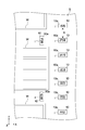
複数の識別子10は、移動体1の走行面S上の所定の位置に所定の姿勢で設置されている。走行面Sは、典型的には、工場等の屋内において移動体1が走行する床面であって、白線W等により荷物置き場と領域的に区画された、X軸方向、Y軸方向又はこれらと交差する方向に延在する直線的又は曲線的な複数の通路を構成する。
複数の識別子10は、X及びY軸方向に沿って一定の間隔で走行面S上に設置され、X及びY軸方向に対して異方性を示す形状を有する。識別子10と識別子10との間の間隔Rは特に限定されず、例えば数十cm~数百cm程度である。
複数の識別子10は、それぞれに異なる第1識別情報Iが付与される。図2の例では、第1識別情報Iが3ケタの英数字で構成されるが、勿論これに限られず、4ケタ以上の文字列等で構成されてもよい(図3、図4参照)。図2に示す第1識別情報Iにおいて、前段の英字記号(「A」、「F」、「C」など)は、個々の通路を特定し、通路間の交差位置は、「P」等の共通の記号が用いられる。後段の数字記号は、各通路での位置情報を表している。
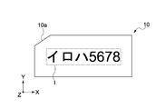
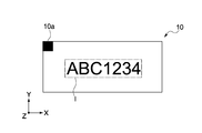
本実施形態に係る識別子10は典型的には矩形状であり、1つの角部に他の角部と異なる角部であることを示す指標部10aが設けられる。この指標部10aは、例えば識別子10の角部に形成された切欠きであり(図3参照)、あるいは、角部に施されたマーキング(図4参照)等である。
これにより、複数の識別子10が図2に示すように、所定の姿勢で一軸方向に規則的に配列されている場合に、切欠きやマーキングを指標として、識別子10が撮像された画像から移動体1の進行方向や向き等を推定することができる。なお、識別子10の形状は典型的には矩形状であるが、これに限られず、三角状やひし形状等その種類は問わない。
図3及び図4は識別子10の構成例を示す図である。第1識別情報Iは走行面S上の識別子10の所在を示す情報であり、走行面Sのアドレスとして機能する。
第1識別情報Iは図3及び図4に示すように、例えば2種類の異なる属性の文字列(識別記号)から構成される。第1識別情報Iを構成する文字列には、典型的には、カタカナやひらがな等の仮名、数字やアルファベット等の英数字、図形等が採用されるがこれに限られず、「@>=-」等の特殊文字や数学記号等が採用されてもよい。
撮像部11は、図1に示すように移動体1の後方に取り付けられ、移動体1の進行方向後方の走行面Sを撮像可能に構成される。撮像部11の光軸の走行面Sに対する傾斜角や画角等の撮像条件は、既知情報として情報処理装置12へ入力される。当該撮像条件は典型的には固定であるが、可変であってもよい。撮像部11は、情報処理装置12に無線又は有線により接続され、撮像した画像を情報処理装置12に出力する。
撮像部11は、例えばCCD(Charge Coupled Device)センサやCMOS(Complementary Metal Oxide Semiconductor)センサ等のイメージセンサを有し、所定のフレームレートで移動体1の進行方向後方の動画を取得する。なお、撮像部11は典型的にはCCDカメラ等のビデオカメラであるが、これに限られず、移動体1の進行方向後方の静止画を所定の撮像間隔で所得可能なスチルカメラやステレオカメラ等であってもよい。
情報処理装置12は、CPU(Central Processing Unit)、ROM(Read Only Memory)、RAM(Random Access Memory)、HDD(Hard Disk Drive)等のコンピュータに必要なハードウェアを有する。CPUが、ROMやHDDに格納されたプログラムをRAMにロードして実行することにより、後述する情報処理装置12の各ブロック動作が制御される。
プログラムは、例えば種々の記憶媒体(内部メモリ)を介して情報処理装置12にインストールされる。あるいは、インターネット等を介してプログラムのインストールが実行されてもよい。本実施形態では、情報処理装置12として、例えば、PC(Personal Computer)やタブレット端末等が用いられるが、他の任意のコンピュータが用いられてもよい。
表示部13は、撮像部11が撮像した画像や、情報処理装置12から出力された画像等を表示可能に構成される。表示部13は、例えば、液晶、有機EL(Electro-Luminescence)等を用いた表示デバイスである。表示部13は、ユーザの操作を入力するための入力部を有する構成であってもよい。当該入力部としては、例えば、タッチパネルや、キーボード等の操作デバイスが採用される。
検出部14は、移動体1に設けられ、情報処理装置12と無線又は有線により接続される。検出部14は、移動体1の移動量を検出し、情報処理装置12に出力可能に構成される。検出部14は、例えば車輪速センサ、加速度センサ、舵角センサ又は角速度センサ等であり、その種類は問わない。
稼働管理システム15は、情報処理装置12から出力された移動体1の走行面S上の位置に関する情報を取得する(図5参照)。稼働管理システム15はこの情報に基づき、表示部13を介して、移動体1を操縦するユーザに現在位置を知らせたり、移動体1をナビゲーションしたり、移動体1の移動軌跡等を管理したりする。
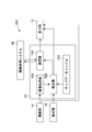
図5は、情報処理装置12の構成例を示す機能ブロック図である。情報処理装置12は、図5に示すように、画像処理部121と、推定部122と、マップデータファイル123と、通信部124と、を有する。
画像処理部121は、撮像部11から取得した画像を処理することにより、画像内の識別子10の第1識別情報Iと、画像内の識別子10と移動体1との相対的な位置関係に関する情報(以下、第2識別情報)とを抽出する。
推定部122は、第1識別情報Iと第2識別情報に基づき、移動体1の走行面S上の位置を推定する。
マップデータファイル123は、識別子10の第1識別情報Iと、当該識別子10の走行面S上の絶対位置とが対応づけられた情報(以下、位置登録データ)を記憶するデータベースである。マップデータファイル123は例えば、第1識別情報Iと走行面S上の識別子10の絶対位置をテキストデータとして表示部13に表示させる。
通信部124は、移動体1の走行面S上の位置に関する情報を稼働管理システム15に出力し、稼働管理システム15から情報を取得可能に構成される。通信部124は、情報処理装置12の入出力インターフェースとして機能する。
<位置推定方法>
図6は、位置推定システム100が移動体1の走行面S上の位置を推定する方法を示すフローチャートである。以下、移動体1の位置推定方法について、図6を適宜参照しながら説明する。
図6は、位置推定システム100が移動体1の走行面S上の位置を推定する方法を示すフローチャートである。以下、移動体1の位置推定方法について、図6を適宜参照しながら説明する。
[適用例1]
(ステップS01:位置登録)
先ず、任意の走行エリア内の走行面S上に、複数の識別子10を一定の間隔で配置する(図2参照)。次に、複数の識別子10に付与された第1識別情報Iと、走行エリア内の複数の識別子10の絶対位置とがそれぞれ対応づけられた位置登録データを作成する。そして。このデータを情報処理装置12に記憶させ、データベース(マップデータファイル123)を構築する。
(ステップS01:位置登録)
先ず、任意の走行エリア内の走行面S上に、複数の識別子10を一定の間隔で配置する(図2参照)。次に、複数の識別子10に付与された第1識別情報Iと、走行エリア内の複数の識別子10の絶対位置とがそれぞれ対応づけられた位置登録データを作成する。そして。このデータを情報処理装置12に記憶させ、データベース(マップデータファイル123)を構築する。
(ステップS02:撮像)
次に、走行面S上を移動する移動体1に取り付けられた撮像部11が、識別子10を撮像する。この際、撮像部11は走行面S上に設置された複数の識別子10のうち少なくとも1つの識別子10を撮像する。なお、本実施形態では、典型的には移動体1の通路上の識別子10が撮像されるが、これに限られず、通路外の識別子10が撮像されてもよい。
次に、走行面S上を移動する移動体1に取り付けられた撮像部11が、識別子10を撮像する。この際、撮像部11は走行面S上に設置された複数の識別子10のうち少なくとも1つの識別子10を撮像する。なお、本実施形態では、典型的には移動体1の通路上の識別子10が撮像されるが、これに限られず、通路外の識別子10が撮像されてもよい。
(ステップS03:識別子の有無の判定)
画像処理部121は、撮像部11から取得した画像について、識別子10が撮像されているか否かを判定する。ここで、画像処理部121は、識別子10が撮像されていると判定した場合(S03のYES)は、後述する画像処理を実行する。
画像処理部121は、撮像部11から取得した画像について、識別子10が撮像されているか否かを判定する。ここで、画像処理部121は、識別子10が撮像されていると判定した場合(S03のYES)は、後述する画像処理を実行する。
(ステップS04;画像処理)
画像処理部121は、撮像部11から取得した画像に所定の画像処理を施す。これにより、画像内の識別子10における第1識別情報Iと、第2識別情報が抽出される。
画像処理部121は、撮像部11から取得した画像に所定の画像処理を施す。これにより、画像内の識別子10における第1識別情報Iと、第2識別情報が抽出される。
本実施形態では、第1識別情報Iを抽出する処理の一例として、画像処理部121は異なる属性の複数の文字列を、同じ属性の文字列(識別記号)毎に抽出する。これにより、第1識別情報I全体を抽出するよりも抽出する情報の種類が限定されるため、画像処理部121が第1識別情報Iを認識する際の誤認識が抑制される。
例えば図3に示した第1識別情報Iは、3ケタの文字列と、4ケタの数字列とにより構成される。画像処理部121は、前段の3ケタはカタカナであり、後段の4ケタは数字であることを予め認識しておくことで、前段の3ケタと後段の4ケタとを相異なる属性として識別できるため、誤認識が抑制される。図4に示した英文字と数字との組み合わせについても同様に、例えば、英文字の「B」と数字の「8」との間の誤認識が確実に防止されるため、第1識別情報Iを高精度に認識することができる。
一方、図7及び図8は、撮像部11が識別子10を撮像した画像Gを示すイメージ図である。第2識別情報を抽出する処理の一例としては、先ず、画像処理部121が撮像部11から取得した画像Gに例えば2値化処理等を施すことにより、画像G内の識別子10の輪郭線や指標部10aを抽出する。これにより、画像G内における識別子10の位置と向きが特定される。
次に、特定した画像G内の識別子10の位置に基づき、第2識別情報として、識別子10と移動体1との間の距離を算出する。具体的には、例えば、画像G内における識別子10以外の領域(余白)の幅L3は、識別子10と移動体1との間の距離に依存するため、画像処理部121は幅L3に基づき、識別子10と移動体1との間の距離を算出する。
さらに、画像処理部121は、特定した画像G内の識別子10の向きに基づき、第2識別情報として、識別子10に対する移動体1の向きを算出する。
具体的には、例えば、画像G内の識別子10の任意の2点E1,E2を通る直線的な仮想線をL1とし、撮像部11の光軸を示す仮想線をL2とした場合に、仮想線L1とL2がなす角度Aを算出することで、識別子10に対する移動体1の向きを算出する。
あるいは、複数の識別子10が一軸方向(配列方向)に沿って所定の姿勢で配列されている場合に、本実施形態に係る識別子10は配列方向に対して異方性を示し、且つ、指標部10aを有するため(図2参照)、例えば図8に示すように仮想線L2と識別子10の長辺又は短辺とがなす角度B,Cや、仮想線L2の配列方向L4からの傾斜角D等と、画像G内の指標部10aの位置を総合的に考慮することで、識別子10に対する移動体1の向きを算出することもできる。
続いて、画像処理部121は、識別子10が撮像された画像から抽出した第1識別情報Iと第2識別情報を推定部122に出力する。
(ステップS05:位置推定)
推定部122は、画像処理部121から取得した第1識別情報Iと、予めマップデータファイル123に登録されている位置登録データとを照合することにより、当該第1識別情報Iが付与された識別子10の走行面S上の絶対位置を特定する。
推定部122は、画像処理部121から取得した第1識別情報Iと、予めマップデータファイル123に登録されている位置登録データとを照合することにより、当該第1識別情報Iが付与された識別子10の走行面S上の絶対位置を特定する。
次いで、推定部122は、特定した走行面S上の識別子10の絶対位置と、この識別子10に対する第2識別情報とに基づき、走行エリア内での移動体1の位置を推定する。
即ち、推定部122は、走行面S上の識別子10の絶対位置と、この識別子10に対する移動体1の相対的な位置関係(距離、向き等)に基づき、移動体1の走行面S上の位置を推定する。これにより、より高精度に移動体1の走行面S上の位置を推定することが可能となる。
また、本実施形態に係る位置推定システム100は、最低限、複数の識別子10、撮像部11及び情報処理装置12を有する構成であれば、移動体1の位置を推定することができる。これにより、従来の例えば無線通信を利用したインフラ協調型のものよりも部品点数を削減することができ、低コスト化を図ることが可能となる。
さらに、位置推定システム100は、建物内部のような制限された空間内で装置構成を完結させることができるため、屋外に限られず、GPS(Global Positioning System)が利用できない屋内においても移動体1の位置を推定することが可能である。
続いて、推定部122は上述した方法により得られた、走行面S上の移動体1の位置に関する情報を表示部13及び通信部124に出力する。これにより、移動体1を操縦するユーザが移動体1の推定位置を確認できる共に、稼働管理システム15を介してこの推定位置が把握される。また、当該位置情報を経時的に蓄積することで、移動体1の運行管理に役立てることができる。
[適用例2]
次に、位置推定システム100が移動体1の走行面S上の位置を推定する別の方法について説明する。なお、適用例1と同様のステップついては、その説明を省略する。
次に、位置推定システム100が移動体1の走行面S上の位置を推定する別の方法について説明する。なお、適用例1と同様のステップついては、その説明を省略する。
(ステップS03:識別子の有無の判定)
画像処理部121は、撮像部11から取得した画像について、識別子10が撮像されているか否かを判定する。ここで、画像処理部121は、識別子10が撮像されていないと判定した場合(S03のNO)は、推定部122が後述する方法により移動体1の位置を推定する。
画像処理部121は、撮像部11から取得した画像について、識別子10が撮像されているか否かを判定する。ここで、画像処理部121は、識別子10が撮像されていないと判定した場合(S03のNO)は、推定部122が後述する方法により移動体1の位置を推定する。
(ステップS05:位置推定)
推定部122は、移動体1に取り付けられた検出部14の出力に基づき、移動体1の走行面S上の位置を推定する。具体的には、推定部122は検出部14が検出した移動体1の走行面S上の移動量から移動体1の位置を推定する。この移動量とは、例えば、直前に撮像した識別子10からの移動距離等である。
推定部122は、移動体1に取り付けられた検出部14の出力に基づき、移動体1の走行面S上の位置を推定する。具体的には、推定部122は検出部14が検出した移動体1の走行面S上の移動量から移動体1の位置を推定する。この移動量とは、例えば、直前に撮像した識別子10からの移動距離等である。
本実施形態に係る位置推定システム100では、移動体1が検出部14を有することにより、移動体1が識別子10と識別子10との間を移動し、識別子10が撮像部11の視野範囲に収められていない場合でも、移動体1の走行面S上の位置を推定することができる。
即ち、直前に撮像された識別子10に基づき推定された走行面S上の移動体1の位置と、当該識別子10に対する移動量から、移動体1の走行面S上の位置を推定することができる。これにより、走行面S上に配置される識別子10の数を削減することができ、低コスト化を図ることが可能となる。
[適用例3]
次に、位置推定システム100が移動体1の走行面S上の位置を推定する別の方法について説明する。なお、適用例1及び2と同様のステップについては、その説明を省略する。
次に、位置推定システム100が移動体1の走行面S上の位置を推定する別の方法について説明する。なお、適用例1及び2と同様のステップについては、その説明を省略する。
(ステップS05:位置推定)
推定部122は、適用例1と同様の手法により推定された走行エリア内での移動体1の位置と、適用例2と同様の手法により検出された当該移動体1の走行面S上の移動量から、走行エリア内での移動体1の位置を推定する。
推定部122は、適用例1と同様の手法により推定された走行エリア内での移動体1の位置と、適用例2と同様の手法により検出された当該移動体1の走行面S上の移動量から、走行エリア内での移動体1の位置を推定する。
即ち、推定部122は、走行面S上の識別子10の絶対位置と、この識別子10に対する移動体1の相対的な位置関係のみならず、検出部14が検出した移動体1の走行面S上の移動量に基づき、走行面S上での移動体1の位置をさらに推定する。これにより、推定部122が走行面S上での移動体1の位置を推定する上での確実性がより向上する。
以上、本発明の実施形態について説明したが、本発明は上述の実施形態にのみ限定されるものではなく種々変更を加え得ることは勿論である。
例えば上記実施形態では、位置推定システム100は、一台の移動体1に適用されることを前提としているが、これに限られず、走行面S上の移動する2台以上の移動体1に適用されてもよい。
また、上記実施形態の位置推定システム100では、情報処理装置12と撮像部11が別体的に設けられた構成であるが、これらが一体的に設けられていてもよい。
さらに、上記実施形態の位置推定システム100は、典型的にはフォークリフトに適用されるが、これに限られない。位置推定システム100は、走行面S上を移動可能な移動体全般に適用されてもよくその用途は問わない。移動体1は有人移動体である場合に限られず、無人移動体であってもよい。
Claims (9)
- 移動体の走行面上の所定の位置に所定の姿勢で設置され、それぞれに異なる第1の識別情報が付与された複数の識別子と、
前記移動体に取り付けられ、前記複数の識別子のうち少なくとも1つの識別子を撮像可能に構成された撮像部と、
前記撮像部により撮像された画像を処理することにより、前記画像内の識別子の前記第1の識別情報と、前記画像内の識別子と前記移動体との相対的な位置関係に関する第2の識別情報とを抽出する画像処理部と、前記第1及び第2の識別情報に基づき、前記移動体の前記走行面上の位置を推定する推定部と、を有する情報処理装置と
を具備する位置推定システム。 - 請求項1に記載の位置推定システムであって、
前記画像処理部は、前記第2の識別情報として、前記画像内の識別子と前記移動体との間の距離を算出する
位置推定システム。 - 請求項1に記載の位置推定システムであって、
前記画像処理部は、前記第2の識別情報として、前記画像内の識別子に対する前記移動体の向きを算出する
位置推定システム。 - 請求項3に記載の位置推定システムであって、
前記画像処理部は、前記複数の識別子が一軸方向に沿って配列された配列方向に対して異方性を有する識別子が撮像された画像を処理することにより、前記移動体の向きを算出する
位置推定システム。 - 請求項4に記載の位置推定システムであって、
前記複数の識別子は矩形状を有し、1つの角部に他の角部と異なる角部であることを示す指標部が設けられ、
前記画像処理部は、前記画像内の前記指標部の位置に基づき、前記移動体の向きを算出する
位置推定システム。 - 請求項1に記載の位置推定システムであって、
前記第1の識別情報は、それぞれ異なる属性の識別記号を少なくとも2種類以上含み、
前記画像処理部は、前記第1の識別情報を、前記識別記号毎に抽出する
位置推定システム。 - 請求項1に記載の位置推定システムであって、
前記情報処理装置は、前記移動体の前記走行面上の位置に関する情報を出力可能に構成された通信部をさらに有する
位置推定システム。 - 請求項1に記載の位置推定システムであって、
前記移動体の移動量を検出可能に構成された検出部をさらに具備し、
前記推定部は、前記推定部により推定された前記移動体の前記走行面上の位置と、前記検出部の出力に基づき、前記移動体の前記走行面上の位置をさらに推定する
位置推定システム。 - 移動体の走行面上の所定の位置に所定の姿勢で設置され、それぞれに異なる第1の識別情報が付与された複数の識別子のうち少なくとも1つの識別子を撮像し、
識別子が撮像された画像を処理することにより、前記画像内の識別子の第1の識別情報と、前記画像内の識別子と前記移動体との相対的な位置関係に関する第2の識別情報とを抽出し、
前記第1及び第2の識別情報に基づき、前記移動体の前記走行面上の位置を推定する
位置推定方法。
Applications Claiming Priority (2)
| Application Number | Priority Date | Filing Date | Title |
|---|---|---|---|
| JP2017134841A JP2019015681A (ja) | 2017-07-10 | 2017-07-10 | 位置推定システム及び位置推定方法 |
| JP2017-134841 | 2017-07-10 |
Publications (1)
| Publication Number | Publication Date |
|---|---|
| WO2019013035A1 true WO2019013035A1 (ja) | 2019-01-17 |
Family
ID=65002447
Family Applications (1)
| Application Number | Title | Priority Date | Filing Date |
|---|---|---|---|
| PCT/JP2018/025150 Ceased WO2019013035A1 (ja) | 2017-07-10 | 2018-07-03 | 位置推定システム及び位置推定方法 |
Country Status (2)
| Country | Link |
|---|---|
| JP (1) | JP2019015681A (ja) |
| WO (1) | WO2019013035A1 (ja) |
Families Citing this family (2)
| Publication number | Priority date | Publication date | Assignee | Title |
|---|---|---|---|---|
| WO2020179386A1 (ja) * | 2019-03-04 | 2020-09-10 | パナソニックIpマネジメント株式会社 | 移動体制御方法、移動体制御システム、及びプログラム |
| KR102887210B1 (ko) * | 2022-09-29 | 2025-11-18 | 네이버 주식회사 | 식별자 인식 기반 위치 결정 방법 및 장치 |
Citations (5)
| Publication number | Priority date | Publication date | Assignee | Title |
|---|---|---|---|---|
| JPH01302408A (ja) * | 1988-05-31 | 1989-12-06 | Hara Ee I Sekkei:Kk | パレット搬送車両の絶対位置及び方向認識方法 |
| JP2007164441A (ja) * | 2005-12-13 | 2007-06-28 | Denso Corp | 移動体方位決定装置、移動体方位決定方法、ナビゲーション装置、および移動可能端末装置 |
| JP2009015684A (ja) * | 2007-07-06 | 2009-01-22 | Komatsu Utility Co Ltd | 配車システム及び方法 |
| WO2016124999A1 (en) * | 2015-02-05 | 2016-08-11 | Grey Orange Pte. Ltd. | Apparatus and method for navigation control |
| US20160271800A1 (en) * | 2015-03-17 | 2016-09-22 | Amazon Technologies, Inc. | Systems and Methods to Facilitate Human/Robot Interaction |
Family Cites Families (1)
| Publication number | Priority date | Publication date | Assignee | Title |
|---|---|---|---|---|
| JP2008309530A (ja) * | 2007-06-12 | 2008-12-25 | National Institute Of Information & Communication Technology | 位置検出装置、それにおける位置の検出をコンピュータに実行させるためのプログラムおよびそのプログラムを記録したコンピュータ読み取り可能な記録媒体 |
-
2017
- 2017-07-10 JP JP2017134841A patent/JP2019015681A/ja active Pending
-
2018
- 2018-07-03 WO PCT/JP2018/025150 patent/WO2019013035A1/ja not_active Ceased
Patent Citations (5)
| Publication number | Priority date | Publication date | Assignee | Title |
|---|---|---|---|---|
| JPH01302408A (ja) * | 1988-05-31 | 1989-12-06 | Hara Ee I Sekkei:Kk | パレット搬送車両の絶対位置及び方向認識方法 |
| JP2007164441A (ja) * | 2005-12-13 | 2007-06-28 | Denso Corp | 移動体方位決定装置、移動体方位決定方法、ナビゲーション装置、および移動可能端末装置 |
| JP2009015684A (ja) * | 2007-07-06 | 2009-01-22 | Komatsu Utility Co Ltd | 配車システム及び方法 |
| WO2016124999A1 (en) * | 2015-02-05 | 2016-08-11 | Grey Orange Pte. Ltd. | Apparatus and method for navigation control |
| US20160271800A1 (en) * | 2015-03-17 | 2016-09-22 | Amazon Technologies, Inc. | Systems and Methods to Facilitate Human/Robot Interaction |
Also Published As
| Publication number | Publication date |
|---|---|
| JP2019015681A (ja) | 2019-01-31 |
Similar Documents
| Publication | Publication Date | Title |
|---|---|---|
| KR102347015B1 (ko) | 창고 환경에서의 차량 추적 | |
| CN110411441B (zh) | 用于多模态映射和定位的系统和方法 | |
| JP6822797B2 (ja) | 標示ベースの位置測定 | |
| US10664675B2 (en) | Code recognition device | |
| US11017244B2 (en) | Obstacle type recognizing method and apparatus, device and storage medium | |
| US10347005B2 (en) | Object state identification method, object state identification apparatus, and carrier | |
| JP4985166B2 (ja) | 自己位置推定装置 | |
| CN103189827B (zh) | 对象显示装置以及对象显示方法 | |
| JP6649796B2 (ja) | 物体状態特定方法、物体状態特定装置、および、搬送車 | |
| KR20200041355A (ko) | 마커를 결합한 동시 위치결정과 지도작성 내비게이션 방법, 장치 및 시스템 | |
| CN108038139B (zh) | 地图构建方法、装置和机器人定位方法、装置、计算机设备和存储介质 | |
| US20210012124A1 (en) | Method of collecting road sign information using mobile mapping system | |
| JP2017054494A5 (ja) | ||
| JP6601613B2 (ja) | 位置推定方法、位置推定装置及び位置推定プログラム | |
| CN112907661B (zh) | 一种移动目标定位方法、装置、电子设备、系统及介质 | |
| CN107817246B (zh) | 存储图像处理程序的介质、图像处理方法及图像处理装置 | |
| JP6479296B2 (ja) | 位置姿勢推定装置および位置姿勢推定方法 | |
| WO2018207426A1 (ja) | 情報処理装置、情報処理方法、及びプログラム | |
| KR20250093255A (ko) | 가상 현실에서 인사이드 아웃 트래킹을 위한 imu 센서 데이터를 활용하는 가속 비전 기반 포즈 추정 방법 | |
| WO2019013035A1 (ja) | 位置推定システム及び位置推定方法 | |
| US11715229B2 (en) | Moving body and system | |
| WO2019201228A1 (zh) | 位置测量方法和位置测量装置 | |
| CN116086455A (zh) | 设备定位方法、装置、设备和存储介质 | |
| JP4984640B2 (ja) | 認識装置、地図データ作成装置および認識方法 | |
| JP2009216480A (ja) | 三次元位置姿勢計測方法および装置 |
Legal Events
| Date | Code | Title | Description |
|---|---|---|---|
| 121 | Ep: the epo has been informed by wipo that ep was designated in this application |
Ref document number: 18832155 Country of ref document: EP Kind code of ref document: A1 |
|
| NENP | Non-entry into the national phase |
Ref country code: DE |
|
| 122 | Ep: pct application non-entry in european phase |
Ref document number: 18832155 Country of ref document: EP Kind code of ref document: A1 |