WO2019013002A1 - めっき液の評価方法及びめっき液の評価機構 - Google Patents
めっき液の評価方法及びめっき液の評価機構 Download PDFInfo
- Publication number
- WO2019013002A1 WO2019013002A1 PCT/JP2018/024540 JP2018024540W WO2019013002A1 WO 2019013002 A1 WO2019013002 A1 WO 2019013002A1 JP 2018024540 W JP2018024540 W JP 2018024540W WO 2019013002 A1 WO2019013002 A1 WO 2019013002A1
- Authority
- WO
- WIPO (PCT)
- Prior art keywords
- plating solution
- plating
- light
- copper sulfate
- fluorescence
- Prior art date
- Legal status (The legal status is an assumption and is not a legal conclusion. Google has not performed a legal analysis and makes no representation as to the accuracy of the status listed.)
- Ceased
Links
Images







Classifications
-
- C—CHEMISTRY; METALLURGY
- C25—ELECTROLYTIC OR ELECTROPHORETIC PROCESSES; APPARATUS THEREFOR
- C25D—PROCESSES FOR THE ELECTROLYTIC OR ELECTROPHORETIC PRODUCTION OF COATINGS; ELECTROFORMING; APPARATUS THEREFOR
- C25D17/00—Constructional parts, or assemblies thereof, of cells for electrolytic coating
-
- C—CHEMISTRY; METALLURGY
- C25—ELECTROLYTIC OR ELECTROPHORETIC PROCESSES; APPARATUS THEREFOR
- C25D—PROCESSES FOR THE ELECTROLYTIC OR ELECTROPHORETIC PRODUCTION OF COATINGS; ELECTROFORMING; APPARATUS THEREFOR
- C25D21/00—Processes for servicing or operating cells for electrolytic coating
- C25D21/12—Process control or regulation
-
- C—CHEMISTRY; METALLURGY
- C25—ELECTROLYTIC OR ELECTROPHORETIC PROCESSES; APPARATUS THEREFOR
- C25D—PROCESSES FOR THE ELECTROLYTIC OR ELECTROPHORETIC PRODUCTION OF COATINGS; ELECTROFORMING; APPARATUS THEREFOR
- C25D21/00—Processes for servicing or operating cells for electrolytic coating
- C25D21/12—Process control or regulation
- C25D21/14—Controlled addition of electrolyte components
-
- G—PHYSICS
- G01—MEASURING; TESTING
- G01N—INVESTIGATING OR ANALYSING MATERIALS BY DETERMINING THEIR CHEMICAL OR PHYSICAL PROPERTIES
- G01N21/00—Investigating or analysing materials by the use of optical means, i.e. using sub-millimetre waves, infrared, visible or ultraviolet light
- G01N21/62—Systems in which the material investigated is excited whereby it emits light or causes a change in wavelength of the incident light
- G01N21/63—Systems in which the material investigated is excited whereby it emits light or causes a change in wavelength of the incident light optically excited
- G01N21/64—Fluorescence; Phosphorescence
Definitions
- the present invention relates to a plating solution evaluation method and a plating solution evaluation mechanism. More specifically, the present invention relates to a method for evaluating a plating solution and a plating solution evaluation method that make it possible to predict the states of a plating solution and a film while performing a plating process on an object to be plated, as well as having a simple configuration.
- a copper plating process is performed in which the surface of a target material is coated with a copper thin film to impart copper characteristics.
- Copper has high thermal conductivity, high electrical conductivity, and excellent spreadability. Copper plating is widely used for various materials such as steel, copper alloy, zinc die casting, plastics, ceramics and the like for decoration and function.
- through-hole plating for printed circuit boards for electronic circuits TSV plating, strike plating for improving adhesion of plating, base plating for decoration, plating on plastic, precision for replication as copper plating processing applications
- electroforming mixed coal prevention with steel materials, etc., printing rolls in gravure printing, etc.
- the main plating baths currently put to practical use include a copper sulfate bath (copper sulfate plating), a copper pyrophosphate bath, a copper cyanide bath, a copper borofluoride bath and the like.
- copper sulfate plating which is a type of electrolytic plating, is easy to work with, and can flow a relatively large current, has good current efficiency, and is suitable for high-speed plating because a high concentration bath can be used. Furthermore, due to the low price and the wide coverage of the object to be plated, copper plating is suitable for industrial use.
- Patent Document 1 a method capable of simply measuring the concentration of monovalent copper in a copper sulfate plating solution which affects the roughness of the copper plating surface and plating defects. That is, by measuring the concentration of monovalent copper in the plating bath as a method of detecting the state change of the plating bath in operation at a factory etc., it is possible to manage the copper sulfate plating solution according to the concentration. .
- Patent Document 1 Although the method for measuring the concentration of monovalent copper sulfate plating solution described in Patent Document 1 described above is one of the techniques that enables the state of the copper sulfate plating solution to be managed in real time, Apart from the formation, there are components that can be focused on from the viewpoint of improving the quality of the plating film and the like.
- the copper sulfate plating solution contains various additives in addition to the base copper sulfate and sulfuric acid for the purpose of improving the performance of the plated film.
- the additives are generally three components of carrier, brightener and leveler, and each additive component is adsorbed on the plating surface to exhibit a unique action. More specifically, the combination of the three components causes the plating to be obtained with excellent gloss, throwing power and leveling ability.
- Janus green which is one of the levelers contributing to the smoothing of the plating film, is consumed (the concentration decreases) with the current application time, but its concentration is 2 mg / in the initial state before the current application. It is a very slight concentration of about L. Therefore, in order to measure the concentration, it was necessary to sample a copper sulfate plating solution and perform mass spectrometry and the like. That is, the concentration of the additive during the plating bath treatment can not be confirmed in situ, and it has been difficult to manage the copper sulfate plating solution regarding the additive.
- the present invention has been made in view of the above points, and is an evaluation of a plating solution which makes it possible to predict the state of a plating solution and a coating while performing a plating process on an object to be plated, as well as having a simple configuration. It is an object of the present invention to provide a method and an evaluation mechanism of a plating solution.
- the present inventors conducted the examination described below about the additive contained in the copper sulfate plating solution, and obtained the knowledge about the present invention.
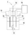
- the beaker 71 is filled with the copper sulfate plating solution 70.
- an anode 76 made of a copper plate and a cathode 75 (a target to be plated) made of a platinum plate are fixed to the beaker 71 via a fixing jig 72, and the tip of each electrode is a copper sulfate plating solution 70.
- the proximal end is connected to the power supply 74.
- the tip of the nozzle 73 connected to a gas supply source (not shown) is immersed in the copper sulfate plating solution 70.
- a rotor 77 is disposed in the beaker 71.
- composition of copper sulfate plating solution 70 The composition of the copper sulfate plating solution 70 is shown below. Copper sulfate: 99.876 g / L (0.4 M / L), sulfuric acid: 49.04 g / L (0.5 M / L), chlorine 50 mg / L (1.41 mM / L), PEG (polyethylene glycol): 0.1 g / L (0.025) mM / L), SPS (3,3'-dithiobis (1-propanesulfonic acid) disodium): 1 mg / L (2.82 ⁇ 10 -3 mM / L), JGB (Janus green B): 2 mg / L (3.91) ⁇ 10 -3 mM / L) Chlorine, PEG, SPS and JGB are additives. Further, the copper sulfate plating solution 70 is a plating solution blended for fine wiring formation technology (damascene).
- the experimental conditions of the energization experiment are as follows. Immersion size of electrode: 40 mm ⁇ 20 mm, bubbling: gas bubbling, current density: 8.1 to 62.5 mA / cm 2 (current value: 0.13 A to 1 A), energization time: 0 to 180 min, beaker capacity: 200 ml (liquid volume: 150 ml) )
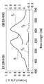
- Fig. 2 shows the fluorescence spectrum (symbol F 1 of Fig. 2) and the excitation spectrum (symbol E 1 of Fig. 2) of a sample with a current density of 62.5 mA / cm 2 (current value 1 A) and a conduction time of 20 min. It shows the and excitation spectrum (code F 2 in FIG. 2) fluorescent spectra in the new liquid sample (code E 2 of Figure 2).
- the horizontal axis is the wavelength
- the vertical axis is the light intensity.
- a fluorescence spectrum is a result at the time of fixing excitation light to wavelength 500nm
- an excitation spectrum is a result at the time of fixing the fluorescence wavelength to detect to 630 nm.
- a fluorescence spectrum having a light emission peak in the vicinity of a wavelength of 600 nm was confirmed in a sample having a current density of 62.5 mA / cm 2 (current value of 1 A) and an energization time of 10 min.
- an excitation spectrum having an absorption (excitation) peak at around 550 nm was confirmed.
- the emission peak and the absorption peak were not confirmed in the sample of the new solution. Therefore, it became clear that the fluorescence which has a luminescence peak in wavelength 600 nm vicinity has arisen by electricity supply to a copper sulfate plating solution.
- fluorescence was generated around a wavelength of 600 nm in the samples (denoted a to e) which were samples after energization and contained JGB.
- the combination of JGB and chlorine has an influence on the increase of fluorescence intensity from the relationship between the code e and the code d
- the combination of the JGB and PEG has an influence on the increase of fluorescence intensity from the relationship between the code e and the code c
- the concentrations in the copper sulfate plating solution are 1.96 ⁇ 10 -3 mM / L, 3.91 ⁇ 10 -3 mM / L, 5.87 ⁇ 10 -3 mM / L and 7.82 ⁇ 10 -3 mM / L from the lowest concentration.
- the excitation light is fixed at a wavelength of 500 nm.
- FIG. 4 (a) shows the change in fluorescence intensity of each sample.
- the horizontal axis is the conduction time (min)
- the vertical axis is the fluorescence intensity at a wavelength of 600 nm.
- the present inventors specified that the generation of fluorescence in the copper sulfate plating solution subjected to the current-passing treatment was caused by JGB.
- Methylene violet is a fluorescent substance with an absorption wavelength of 554 nm.
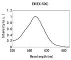
- FIG. 5 shows a fluorescence spectrum of the sample after the current density of 31.3 mA / cm 2 (current value of 0.5 A) and the current application time of 12 minutes in the above-described experiment (1) of applying current to the copper sulfate plating solution. Also in the same sample, the fluorescence spectrum of methylene violet generated by the decomposition of JGB was confirmed. Furthermore, although not shown, in the measurement of the excitation spectrum of the same sample, a clear excitation peak was confirmed around the wavelength of 545 nm.
- the generation of fluorescence in the copper sulfate plating solution is a phenomenon that responds extremely sensitively to the current, and the generation of fluorescence can be sufficiently detected even under conditions where the value of the current density is small or for a short time. It became clear. From this, the present inventors have found the possibility that the decreasing tendency of JGB can be detected by measuring the fluorescence intensity from the initial stage during the plating treatment with a copper sulfate plating solution.
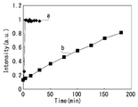
- the graph indicated by symbol a in FIG. 8 is a sample using a copper plate for the anode
- the graph indicated by symbol b is a sample using phosphorus-containing copper as the anode.
- the increase in fluorescence intensity with the passage of time after the start of energization was slower than in the sample of the copper plate.
- the generation of fluorescence accompanying the decomposition of JGB occurs even when phosphorus-containing copper is used for the anode.
- the measurement of the fluorescence intensity of wavelength 600nm can be utilized as an evaluation index of a sulfated copper plating solution, even if it uses phosphorus-containing copper for an anode.
- an object to be plated using a plating solution containing an additive is subjected to at least the plating solution in order to detect unevenness of a film. Irradiating light of a predetermined wavelength.
- the additive in the plating solution, it is possible to capture a decrease in the additive that affects the plating film and the like, and use it as an index for evaluating the condition of the plating solution and the plating film. That is, for example, it is possible to detect whether or not the copper sulfate plating solution is in an appropriate state for the plating process by confirming the decrease of the predetermined additive. Further, along with this, it is possible to obtain prediction information of the quality of the plated film, for example, the presence or absence and the degree of uneven color, rough or rough surface, glossiness and the like.
- the plating solution by irradiating the plating solution with light of a predetermined wavelength, it is possible to use information on changes in physical properties of light such as absorption, transmission, reflection, and scattering of light generated in the plating solution. For example, information of fluorescence generated by components contained in the plating solution and information of light scattering in the plating solution can be obtained. These pieces of information can be used as information for confirming the state of the plating solution.
- the present inventors also estimate that there is a correlation between the increase in the light scattering intensity in the copper sulfate plating solution and the occurrence of surface roughening in the plating film. Therefore, by irradiating light of a predetermined wavelength to the copper sulfate plating solution and measuring the light scattering intensity in the copper sulfate plating solution, it can be used as prediction information of roughness on the surface of the plated film.
- the plating solution by irradiating the plating solution with light of a predetermined wavelength in order to detect at least the unevenness of the film, based on the information on the change in physical properties of the light such as absorption, transmission, reflection, and scattering of light generated in the plating solution.
- the presence or absence and degree of unevenness of the plated film can be predicted.
- the additive is a dye molecule having at least an azo group
- decomposition of the additive contained in the plating solution that is, fluorescence emitted by a product generated by reductive cleavage of the azo group is It can be used as an indicator of condition evaluation. Also, this makes it possible to predict the deterioration of the smoothness of the plated film due to the consumption of the additive and the unevenness of the film by light irradiation and fluorescence detection.
- disassembly of Janus green contained in a plating solution can be made into the parameter
- the wavelength is excited by light in the range of 495 to 570 nm, and plating is performed by detecting the fluorescence intensity emitted thereby. It becomes possible to evaluate the condition of the solution and the plating film.
- the plating solution is irradiated with light of a predetermined wavelength in order to detect unevenness of the film in addition to unevenness of the film for the object to be plated
- information on scattering of light generated in the plating solution is used. Not only unevenness of the plating film, but also roughening of the plating film, for example, generation of a concavo-convex structure on the surface of the plating film, and remarkable generation of massive particles can be predicted.
- the evaluation mechanism of the plating solution of the present invention comprises: a plating apparatus having a plating tank filled with a plating solution containing an additive; and the plating solution with light at a predetermined wavelength. And an illuminable light source generation means.
- the plating solution contains an additive
- the decrease in the additive that affects the plating film and the like can be grasped and can be used as an index for evaluating the condition of the plating solution and the plating film.
- an additive will be consumed and it will reduce, but since an additive is replenished in order to ensure the quality of a plating film after this, a plating solution is In principle, it will be returned to the state of containing the additive.
- the light source generating means capable of irradiating the plating solution with light at a predetermined wavelength can utilize information on changes in physical properties of light such as absorption, transmission, reflection, and scattering of light generated in the plating solution.
- the information of the physical-property change of light it can detect with the known light detection apparatus, for example, photomultiplier, CCD, a photodiode etc.
- the known light detection apparatus for example, photomultiplier, CCD, a photodiode etc.
- it is the presence or absence of fluorescence etc. it is possible to detect also by visual observation.
- each area of the plating tank filled with the plating solution is irradiated with the light of the predetermined wavelength.
- State evaluation of the plating solution in the area can be performed. For example, even in the same plating solution, it is assumed that the state of the plating solution is different in the vicinity of the electrode and in the area away from the electrode. Since a large-scale plating tank is used at the industrial level, it is considered that the change in the state of the plating solution is also noticeable due to the difference in the position in the plating tank. Therefore, it becomes possible to compare the detection information of different irradiation areas, and to utilize it as reference information for optimizing the plating processing conditions such as the size and structure of the plating tank, bubbling and stirring conditions.
- the method for evaluating a plating solution according to the present invention has a simple configuration, and is a method capable of predicting the states of a plating solution and a film while performing a plating process on an object to be plated.
- the evaluation mechanism of the plating solution according to the present invention has a simple configuration and is a method capable of predicting the state of the plating solution and the film while performing the plating process on the object to be plated.
- FIG. 1 is a schematic view showing an example of an evaluation mechanism of a copper sulfate plating solution to which the present invention is applied.
- the structure shown below is an example of the present invention, and the contents of the present invention are not limited to this.
- An evaluation mechanism 1 for a copper sulfate plating solution shown in FIG. 1 includes a plating tank 2, a light source 3, a light chopper 4, a lens 5, and a light detection mechanism 6.
- the plating tank 2 is a reaction system in which a copper sulfate plating process is performed.
- the light source 3 is a light source of the laser beam to be irradiated with laser light L 1 having a predetermined wavelength to the plating tank 2, the wavelength of the irradiating light is adjustable configuration in the range of 495 ⁇ 570 nm. Furthermore, the light source 3 is configured to be able to change the irradiation position of the irradiation light, and the light can be irradiated to a desired area in the plating tank 2 filled with the copper sulfate plating solution 20.
- the write chopper 4 by intermittent laser light L 1 of the light source 3 is a device that allows distinguished from ambient light.
- the laser beam L 1 irradiated to the copper sulfate plating solution 20 filled in the plating tank 2 is emitted, absorbed, transmitted, reflected, scattered and the like in the copper sulfate plating solution 20 and emitted light L 2 Are collected and supplied to the light detection mechanism 6.
- the light detection mechanism 6 is a part that detects various information included in the emitted light L 2 and acquires information that is an index for evaluating the state of the copper sulfate plating solution 20 and the state of the plating film.
- a beaker 21 is filled with a copper sulfate plating solution 20.
- the copper sulfate plating solution 20 contains Janus green.
- an anode 26 and a cathode 25 are fixed to the beaker 21 via a fixing jig 22.
- the anode 26 and the cathode 25 are connected to a power supply 24 so that the copper sulfate plating solution 20 can be energized.
- the plating tank 2 has the nozzle 23 connected to the gas supply source which is not shown in figure.
- the light detection mechanism 6 has a photomultiplier 61, a lock-in up 62, and a terminal 63 for information analysis.
- the photomultiplier 61 is a high sensitivity photodetector that converts and amplifies the light energy of the outgoing light L2 into electrical energy.
- the lock-in amplifier 62 is connected to the light chopper 4 and synchronizes the signal output from the photomultiplier 61 to remove noise during measurement.
- the terminal 63 is a device for converting into output information to be analyzed or output by a software function or the like according to the type of output signal.
- the information detected by the photomultiplier 61 is, for example, the fluorescence intensity of the emitted light L 2 , and the degradation (density decrease) of Janus green contained in the copper sulfate plating solution 20 is confirmed using the information of the measured fluorescence intensity as an index be able to.
- the light source 3 does not necessarily have to be configured to be able to adjust the wavelength of the irradiation light. It may be a light source that emits only a single wavelength, as long as it can emit information of light finally detected, for example, light of a wavelength that can obtain fluorescence intensity.
- the light source 3 does not necessarily have to be configured to be able to change the irradiation position of the irradiation light.
- the light source 3 is configured to be able to change the irradiation position of the irradiation light.
- a known variable mechanism such as manual or motor drive can be adopted.
- the light detection mechanism 6 does not necessarily have to be configured by the photomultiplier 61.
- a photodetector having a spectral function such as a spectrophotometer. In this case, not only the prediction of the occurrence of the unevenness of the plating film by the measurement of the fluorescence intensity, but also the roughness of the film generated on the plating film can be predicted by measuring the light scattering intensity.
- the evaluation mechanism of the copper sulfate plating solution to which the present invention is applied can measure on-time the degradation of Janus green contained in the copper sulfate plating solution using fluorescence intensity. Based on this measurement result, it is possible to evaluate the state of copper sulfate plating.
- the measurement system can be easily provided in accordance with the site where the plating tank is arranged.
- the measurement of the fluorescence intensity by a light detection mechanism has become possible for easy and highly sensitive measurement. Furthermore, by devising the illumination of the environment where the plating tank is provided, etc., it is also possible to visually detect the fluorescence, so measurement can be performed by a simple evaluation mechanism without introducing a special light detection device. it can. In addition, it is also possible to measure the change of a specific area with high time resolution by incorporating a light collecting function by a lens.
- the evaluation method of the copper sulfate plating solution according to the present invention has a simple configuration, and a method capable of predicting the state of the copper sulfate plating solution and the film while performing the plating treatment on the object to be plated It has become.
- the evaluation mechanism of the copper sulfate plating solution according to the present invention has a simple configuration and is a method capable of predicting the state of the copper sulfate plating solution and the coating while performing plating on the object to be plated. .
- Copper sulfate plating treatment was performed under the following conditions to evaluate the quality of the plating film.
- the plating treatment was performed using a plating bath in which the copper sulfate plating solution 70 was filled in the test apparatus configuration 7 described above.
- the plating process was performed for 30 minutes while rotating the rotor at 1,000 rpm at a current density of 15.6 mA / cm 2 (current value: 0.2 A).
- As a copper sulfate plating solution before (0 min), for 4 min, 8 min, 16 min, 30 min for current treatment, and for the solution for which 30 min current has been applied, JGB is added again (replenished) by concentration for our location It was.
- FIG. 10 is a graph showing a time-dependent change in fluorescence intensity at a wavelength of 600 nm of a sample in this test.
- 11 and 12 are photographic data
- FIG. 13 is a 1000 ⁇ SEM image
- FIG. 14 is a 30000 ⁇ SEM image.
- the sample before energization (0 min) had a slight surface roughness and a semi-glossy appearance.
- the surface of 8 min was observed to be spread in white roughness as a whole, and semi-gloss was observed.
- the surface for 16 min was uneven in color as a whole and had no gloss.
- the surface for 30 minutes had a whitish color unevenness as a whole, was not glossy and was rough.
- the surface re-added with JGB had an overall whitish color unevenness and roughness, but a semi-glossy appearance.
- the surface in each sample looks like a uniform surface in the 1000 ⁇ SEM image (see FIG. 13)
- the 30000 ⁇ SEM image shown in FIG. 14 shows the clean surface seen in the sample before energization (0 min)
- the particles on the surface became large, and the concavo-convex structure became noticeable.
- the surface on which JGB was re-added after 30 minutes had the same texture as the surface of the 4 min sample.
- a spectrophotometer is used as a light detection mechanism for the above-described measurement system of fluorescence intensity, and copper sulfate plating treatment is performed on the same copper sulfate plating solution
- the fluorescence intensity and the light scattering intensity were measured.
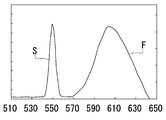
- the light scattering intensity has a peak at a wavelength of 550 nm, which is due to the wavelength of the light serving as the light source.
- the fluorescence intensity has a peak at around a wavelength of 600 nm.
Landscapes
- Chemical & Material Sciences (AREA)
- Engineering & Computer Science (AREA)
- Chemical Kinetics & Catalysis (AREA)
- Electrochemistry (AREA)
- Materials Engineering (AREA)
- Metallurgy (AREA)
- Organic Chemistry (AREA)
- Automation & Control Theory (AREA)
- Health & Medical Sciences (AREA)
- Physics & Mathematics (AREA)
- Nuclear Medicine, Radiotherapy & Molecular Imaging (AREA)
- Life Sciences & Earth Sciences (AREA)
- Analytical Chemistry (AREA)
- Biochemistry (AREA)
- General Health & Medical Sciences (AREA)
- General Physics & Mathematics (AREA)
- Immunology (AREA)
- Pathology (AREA)
- Investigating, Analyzing Materials By Fluorescence Or Luminescence (AREA)
- Electroplating And Plating Baths Therefor (AREA)
Abstract
【課題】簡易な構成であるとともに、被めっき対象物にめっき処理を施しながら、めっき液及び被膜の状態を予測可能にするめっき液の評価方法及びめっき液の評価機構を提供する。 【解決手段】本発明を適用した硫酸銅めっき液の評価機構の一例である硫酸銅めっき液の評価機構1は、めっき槽2と、光源3と、ライトチョッパ4と、レンズ5と、光検出機構6を備えている。
Description
本発明はめっき液の評価方法及びめっき液の評価機構に関する。詳しくは、簡易な構成であるとともに、被めっき対象物にめっき処理を施しながら、めっき液及び被膜の状態を予測可能にするめっき液の評価方法及びめっき液の評価機構に係るものである。
従来、表面処理の一種として、対象となる材料の表面を銅の薄膜で被覆して、銅の特性を付与する銅めっき処理が行われている。銅は熱伝導性、電気伝導性が高く、展延性に優れる性質を有している。銅めっき処理は、鉄鋼や銅合金、亜鉛ダイカスト、プラスチック、セラミックス等の様々な素材に装飾用、機能用として幅広く利用されている。
例えば、銅めっき処理の用途として、電子回路用プリント基板のスルーホールめっき、TSVめっき、めっきの密着性を向上させるためのストライクめっき、装飾の下地めっき、プラスチック上へのめっき、複製のための精密電鋳、鋼材等での混炭防止、グラビア印刷における印刷ロール等が存在する。
また、銅めっき処理において、現在実用化されている主なめっき浴は、硫酸銅浴(硫酸銅めっき)、ピロリン酸銅浴、シアン化銅浴、ホウフッ化銅浴等がある。
特に、電解めっきの一種である硫酸銅めっきは、作業が容易であり、比較的大きな電流が流せて、電流効率が良く、高濃度浴が使用できるため高速度めっきに適している。更に、価格の安さや、被めっき対象物の対象範囲が広いことから、銅めっきの中でも産業レベルでの活用に適している。
このような産業レベルで活用する硫酸銅めっき処理では、めっき表面の品質の確保や、めっきの不良率を低減することが当然重要となる。また、大型・多量の被めっき対象物の処理や、長時間に渡るめっき処理を行うことから、めっき浴の状態をリアルタイムで管理することが求められている。
こうしたなか、本発明者らは、銅めっき表面のざらつきや、めっき不良に影響を及ぼす硫酸銅めっき液中の一価銅濃度を簡便に測定可能な方法を考案している(例えば、特許文献1参照)。即ち、工場等で稼働中のめっき浴の状態変化を捉える方法として、めっき浴中の一価銅の濃度を測定することで、その濃度に応じた硫酸銅めっき液の管理を可能となっている。
ここで、上述した特許文献1に記載の硫酸銅めっき液の一価銅の濃度測定方法は、硫酸銅めっき液の状態をリアルタイムで管理可能とする技術の1つではあるが、一価銅の生成以外にも、めっき被膜の品質等を向上させる観点から着目しうる構成要素が存在する。
硫酸銅めっき液には、ベースとなる硫酸銅、硫酸の他に、めっき被膜の性能を向上させる目的から、各種添加剤が配合される。添加剤はキャリアー、ブライトナー、レベラーの三成分が一般的であり、各添加剤成分は、めっき表面に吸着して特有の作用を示す。より詳細には、三成分が複合的に作用しあうことで、光沢性、均一電着性、レべリング性に優れためっきが得られるものとなる。
このような硫酸銅めっき液中の添加剤成分には、電気めっき処理において通電を継続的に行うと消費され、新たに硫酸銅めっき液中に添加する必要が生じるものがある。
例えば、めっき被膜の平滑化に寄与するレベラーの1種であるヤヌスグリーンは、通電時間に伴い、消費されていく(濃度が下がっていく)が、その濃度は通電前の初期状態において、2mg/L程度の非常に微量な濃度である。そのため、濃度を測定するためには、硫酸銅めっき液をサンプリングして、質量分析法等を行う必要があった。即ち、めっき浴処理中の添加剤の濃度をその場で確認することができず、添加剤に関する硫酸銅めっき液の管理を行うことが困難であった。
本発明は、以上の点に鑑みて創案されたものであり、簡易な構成であるとともに、被めっき対象物にめっき処理を施しながら、めっき液及び被膜の状態を予測可能にするめっき液の評価方法及びめっき液の評価機構を提供することを目的とする。
本発明者らは、硫酸銅めっき液に含有する添加剤について以下で説明する検討を行い、本発明に関する知見を得た。
[硫酸銅めっき液における蛍光検出]
(1)硫酸銅めっき液への通電実験
本発明者らは、硫酸銅めっき液に通電処理を行うと、波長600nm付近の赤色領域に蛍光が生じることを観察した。図1に示す装置構成と、下記の条件で硫酸銅めっき液に通電処理を行い、蛍光スペクトルと励起スペクトルを確認した。
(1)硫酸銅めっき液への通電実験
本発明者らは、硫酸銅めっき液に通電処理を行うと、波長600nm付近の赤色領域に蛍光が生じることを観察した。図1に示す装置構成と、下記の条件で硫酸銅めっき液に通電処理を行い、蛍光スペクトルと励起スペクトルを確認した。
図1に示すように、実験装置構成7では、ビーカー71に硫酸銅めっき液70を充填している。また、銅板で構成された陽極76と、白金板で構成された陰極75(被めっき対象物)が固定治具72を介してビーカー71に固定され、各電極の先端側が硫酸銅めっき液70に浸され、基端側が電源74に接続されている。また、図示しないガス供給源に接続されたノズル73の先端が硫酸銅めっき液70に浸されている。また、ビーカー71の中に回転子77が配置されている。
(硫酸銅めっき液70の組成)
硫酸銅めっき液70の組成を以下に示す。
硫酸銅:99.876g/L(0.4M/L)、硫酸:49.04g/L(0.5M/L)、塩素50mg/L(1.41mM/L)、PEG(ポリエチレングリコール):0.1g/L(0.025mM/L)、SPS(3,3'-ジチオビス(1-プロパンスルホン酸)2ナトリウム):1mg/L(2.82×10-3mM/L)、JGB(ヤヌスグリーンB):2mg/L(3.91×10-3mM/L)
なお、塩素、PEG、SPS及びJGBは添加剤である。また、硫酸銅めっき液70は、微細配線形成技術(ダマシン)用に配合されためっき液である。
硫酸銅めっき液70の組成を以下に示す。
硫酸銅:99.876g/L(0.4M/L)、硫酸:49.04g/L(0.5M/L)、塩素50mg/L(1.41mM/L)、PEG(ポリエチレングリコール):0.1g/L(0.025mM/L)、SPS(3,3'-ジチオビス(1-プロパンスルホン酸)2ナトリウム):1mg/L(2.82×10-3mM/L)、JGB(ヤヌスグリーンB):2mg/L(3.91×10-3mM/L)
なお、塩素、PEG、SPS及びJGBは添加剤である。また、硫酸銅めっき液70は、微細配線形成技術(ダマシン)用に配合されためっき液である。
(実験パラメータ)
通電実験の実験条件は次のとおりである。
電極の浸漬サイズ:40mm×20mm、バブリング:ガスバブリング、電流密度:8.1~62.5mA/cm2(電流値:0.13A~1A)、通電時間:0~180min、ビーカー容量:200ml(液容量:150ml)
通電実験の実験条件は次のとおりである。
電極の浸漬サイズ:40mm×20mm、バブリング:ガスバブリング、電流密度:8.1~62.5mA/cm2(電流値:0.13A~1A)、通電時間:0~180min、ビーカー容量:200ml(液容量:150ml)
図2に電流密度62.5mA/cm2(電流値1A)、通電時間20minのサンプルにおける蛍光スペクトル(図2の符号F1)及び励起スペクトル(図2の符号E1)と、通電をしていない新液のサンプルにおける蛍光スペクトル(図2の符号F2)及び励起スペクトル(図2の符号E2)を示す。なお、図2に示すスペクトルにおいて横軸は波長、縦軸は光の強度である。また、蛍光スペクトルは、励起光を波長500nmに固定した際の結果であり、励起スペクトルは、検出する蛍光波長を630nmに固定した際の結果である。
図2に示すように、電流密度62.5mA/cm2(電流値1A)、通電時間10minのサンプルにおいて、波長600nm付近に発光ピークを有する蛍光スペクトルが確認された。また、550nm付近に吸収(励起)ピークを有する励起スペクトルが確認された。一方、新液のサンプルにおいては、発光ピーク及び吸収ピークは確認されなかった。従って、硫酸銅めっき液への通電によって、波長600nm付近に発光ピークを有する蛍光が生じていることが明らかとなった。
(2)硫酸銅めっき液成分と蛍光出現の関係
続いて、硫酸銅めっき液の組成中のどの成分が蛍光の発生に寄与しているかを確認するための検討を行った。上述した図1に示す実験装置構成7を用いて、硫酸銅めっき液を構成する成分を変えて、電流密度62.5mA/cm2(電流値1A)、通電時間10min後の各サンプルの蛍光強度を測定した。なお、励起光は波長500nmに固定している。
図3に各サンプルの蛍光スペクトルを示す。図3に示す各スペクトルとサンプルとの対応関係は次のようになっている。
符号a:硫酸銅めっき液70(全成分)
符号b:硫酸銅原液+塩素+PEG+JGB
符号c:硫酸銅原液+PEG+JGB
符号d:硫酸銅原液+塩素+JGB
符号e:硫酸銅原液+JGB
符号f:硫酸銅めっき液70(全成分)で、通電をしていない新液
符号g:硫酸銅原液+塩素+PEG
符号h:硫酸銅原液+塩素+PEG+SPS
続いて、硫酸銅めっき液の組成中のどの成分が蛍光の発生に寄与しているかを確認するための検討を行った。上述した図1に示す実験装置構成7を用いて、硫酸銅めっき液を構成する成分を変えて、電流密度62.5mA/cm2(電流値1A)、通電時間10min後の各サンプルの蛍光強度を測定した。なお、励起光は波長500nmに固定している。
図3に各サンプルの蛍光スペクトルを示す。図3に示す各スペクトルとサンプルとの対応関係は次のようになっている。
符号a:硫酸銅めっき液70(全成分)
符号b:硫酸銅原液+塩素+PEG+JGB
符号c:硫酸銅原液+PEG+JGB
符号d:硫酸銅原液+塩素+JGB
符号e:硫酸銅原液+JGB
符号f:硫酸銅めっき液70(全成分)で、通電をしていない新液
符号g:硫酸銅原液+塩素+PEG
符号h:硫酸銅原液+塩素+PEG+SPS
図3に示すように、通電後のサンプルであって、JGBを含有するサンプル(符号a~e)において、波長600nm付近の蛍光が生じていた。また、符号eと符号dの関係からJGBと塩素の組み合わせが蛍光強度の増加に影響がある点、符号eと符号cの関係からJGBとPEGの組み合わせが蛍光強度の増加に影響がある点、更に、符号eと符号bの関係からJGBと塩素とPEGの組み合わせが、蛍光強度の増加により一層影響がある点が示された。従って、通電後の硫酸銅めっき液における波長600nm付近の蛍光の発生には、JGBが発光中心として関与しており、更に、塩素とPEGが影響していることが推測された。
(3)JGB濃度の違いと蛍光強度の変化
硫酸銅めっき液におけるJGBの濃度と蛍光強度との関連性を確認するための検討を行った。上述した図1に示す実験装置構成7を用いて、硫酸銅めっき液を構成するJGBの濃度を変えて、電流密度62.5mA/cm2(電流値1A)の通電処理を行い、経過時間ごとの波長600nmの蛍光強度を測定した。硫酸銅めっき液における濃度は、濃度の低い方から1.96×10-3mM/L、3.91×10-3mM/L、5.87×10-3mM/L、及び7.82×10-3mM/Lの4段階とした。なお、励起光は波長500nmに固定している。
図4(a)に各サンプルの蛍光強度の変化を示す。図4(a)は横軸が通電時間(min)、縦軸が波長600nmの蛍光強度である。
硫酸銅めっき液におけるJGBの濃度と蛍光強度との関連性を確認するための検討を行った。上述した図1に示す実験装置構成7を用いて、硫酸銅めっき液を構成するJGBの濃度を変えて、電流密度62.5mA/cm2(電流値1A)の通電処理を行い、経過時間ごとの波長600nmの蛍光強度を測定した。硫酸銅めっき液における濃度は、濃度の低い方から1.96×10-3mM/L、3.91×10-3mM/L、5.87×10-3mM/L、及び7.82×10-3mM/Lの4段階とした。なお、励起光は波長500nmに固定している。
図4(a)に各サンプルの蛍光強度の変化を示す。図4(a)は横軸が通電時間(min)、縦軸が波長600nmの蛍光強度である。
図4(a)に示すように、JGBの濃度上昇に伴い、発生する波長600nmの蛍光強度は大きくなった。また、濃度に関わらず、通電開始後5分程度で蛍光強度は一定値で最大になり、それ以後の顕著な増減が確認されなかった。この結果、通電により硫酸銅めっき液に生じる波長600nmの蛍光強度は、JGBの濃度に比例することが明らかとなった。なお、図4(b)にJGB濃度と通電開始20分経過後の波長600nmの蛍光強度との関係をグラフに示している。
上記の検討から、本発明者らは、通電処理を行った硫酸銅めっき液での蛍光の発生はJGBに起因するものであることを特定した。また、JGBからの蛍光が発生する現象は、硫酸銅めっき液中における一価の銅イオンが酸化(Cu+→Cu2+)されるのに伴い、JGBの化学構造中のアゾ基(N=N)の部分の化学結合が還元的切断を受け、メチレンバイオレット(Methylene Violet)とフェニレンジアミン(Phenylenediamine)が形成されることによるものと推測される。メチレンバイオレットは、吸収波長554nmの蛍光物質である。
また、上述した(1)硫酸銅めっき液への通電実験における、電流密度31.3mA/cm2(電流値0.5A)、通電時間12min後のサンプルの蛍光スペクトルを図5に示す。同サンプルにおいても、JGBの分解により生じたメチレンバイオレットの蛍光スペクトルが確認された。更に、図示しないが、同サンプルでの励起スペクトルの測定では、波長545nm付近に明確な励起ピークが確認された。
(4)電流密度と蛍光強度との関係
上述した(1)硫酸銅めっき液への通電実験における結果から、電流密度と蛍光強度との関係性を調べるために、JGBの濃度が2mg/L(3.91×10-3mM/L)の硫酸銅めっき液に対して、通電して20分経過後における電流密度が異なるサンプルの蛍光スペクトル及び励起スペクトルを確認した。
図6に、電流密度62.5mA/cm2(電流値1A)のサンプルにおける蛍光スペクトル(図6の符号F1)及び励起スペクトル(図6の符号E1)、電流密度31.3mA/cm2(電流値0.5A)のサンプルにおける蛍光スペクトル(図6の符号F2)及び励起スペクトル(図6の符号E2)、電流密度15.6mA/cm2(電流値0.25A)のサンプルにおける蛍光スペクトル(図6の符号F3)及び励起スペクトル(図6の符号E3)、及び、通電をしていない新液のサンプルにおける蛍光スペクトル(図6の符号F4)及び励起スペクトル(図6の符号E4)を示す。なお、図6に示す蛍光スペクトルは、励起光を波長500nmに固定した際の結果であり、励起スペクトルは、検出する蛍光波長を630nmに固定した際の結果である。
上述した(1)硫酸銅めっき液への通電実験における結果から、電流密度と蛍光強度との関係性を調べるために、JGBの濃度が2mg/L(3.91×10-3mM/L)の硫酸銅めっき液に対して、通電して20分経過後における電流密度が異なるサンプルの蛍光スペクトル及び励起スペクトルを確認した。
図6に、電流密度62.5mA/cm2(電流値1A)のサンプルにおける蛍光スペクトル(図6の符号F1)及び励起スペクトル(図6の符号E1)、電流密度31.3mA/cm2(電流値0.5A)のサンプルにおける蛍光スペクトル(図6の符号F2)及び励起スペクトル(図6の符号E2)、電流密度15.6mA/cm2(電流値0.25A)のサンプルにおける蛍光スペクトル(図6の符号F3)及び励起スペクトル(図6の符号E3)、及び、通電をしていない新液のサンプルにおける蛍光スペクトル(図6の符号F4)及び励起スペクトル(図6の符号E4)を示す。なお、図6に示す蛍光スペクトルは、励起光を波長500nmに固定した際の結果であり、励起スペクトルは、検出する蛍光波長を630nmに固定した際の結果である。
図6に示すように、異なる電流密度(電流値)で20分間の通電処理を行うと、波長600nm付近の赤色領域に蛍光が確認された。電流密度の値が異なっても、蛍光強度はほぼ同程度であり、大きな差は見られなかった。なお、各サンプルでの励起スペクトルはほぼ一致していた(図6中の符号E1~E4のスペクトル参照)。
(5)電流密度と通電時間の関係
上述した(1)硫酸銅めっき液への通電実験における結果から、電流密度と通電時間との関係性を調べるために、JGBの濃度が2mg/L(3.91×10-3mM/L)の硫酸銅めっき液に対して、通電開始後の経過時間ごとの電流密度が異なるサンプルの蛍光強度を確認した。
図7に結果を示す。図7における各グラフと電流密度との対応関係は次のようになっている。
符号a:電流密度62.5mA/cm2(電流値1A)
符号b:電流密度31.3mA/cm2(電流値0.5A)
符号c:電流密度21.9mA/cm2(電流値0.35A)
符号d:電流密度15.6mA/cm2(電流値0.25A)
符号e:電流密度12.5mA/cm2(電流値0.2A)
符号f:電流密度8.1mA/cm2(電流値0.13A)
上述した(1)硫酸銅めっき液への通電実験における結果から、電流密度と通電時間との関係性を調べるために、JGBの濃度が2mg/L(3.91×10-3mM/L)の硫酸銅めっき液に対して、通電開始後の経過時間ごとの電流密度が異なるサンプルの蛍光強度を確認した。
図7に結果を示す。図7における各グラフと電流密度との対応関係は次のようになっている。
符号a:電流密度62.5mA/cm2(電流値1A)
符号b:電流密度31.3mA/cm2(電流値0.5A)
符号c:電流密度21.9mA/cm2(電流値0.35A)
符号d:電流密度15.6mA/cm2(電流値0.25A)
符号e:電流密度12.5mA/cm2(電流値0.2A)
符号f:電流密度8.1mA/cm2(電流値0.13A)
図7に示すように、符号aで示す電流密度62.5mA/cm2(電流値1A)のサンプルでは、通電開始直後に蛍光強度が大きく増加して、通電開始から5分経過する前に、蛍光強度は最大となり、その後の増減はなかった。符号bで示す電流密度31.3mA/cm2(電流値0.5A)及び符号cで示す電流密度21.9mA/cm2(電流値0.35A)においても、通電開始から5分経過後ぐらいから蛍光強度が大きく増加して、通電開始から10分前後で蛍光強度は最大となり、その後の増減はなかった。符号dで示す電流密度15.6mA/cm2(電流値0.25A)を含め、それ以下の電流密度の小さなサンプルでは、通電開始の時間経過に応じて蛍光強度が増加する傾向が確認された。
これらの結果から、硫酸銅めっき液における蛍光の発生は、電流に極めて敏感に応答する現象であり、電流密度の値が小さな条件や、短い通電時間でも蛍光の発生が充分に検知可能であることが明らかとなった。このことから、本発明者らは、硫酸銅めっき液でのめっき処理中の初期の段階から、JGBの減少傾向を蛍光強度の測定により検知できる可能性を見出した。
(6)陽極の材料の違いによる検討
上述の各検討では、陽極に銅版を用いた装置を用いていたが、陽極に含燐銅を使用した場合にも、通電処理によって硫酸銅めっき液で蛍光が検出可能か否かを確認した。含燐銅は、めっき被膜の品質を損なう一価銅が生成しない陽極材料であり、産業的な硫酸銅めっき処理において一般的に用いられている。
本検討では、電流密度62.5mA/cm2(電流値1A)で、通電開始からの時間経過ごとの波長600nmの蛍光強度を測定した。図8に結果を示すが、図8における符号aで示すグラフが陽極に銅板を用いたサンプル、符号bで示すグラフが陽極に含燐銅を用いたサンプルである。
図8に示すように、陽極に含燐銅を用いたサンプルでは、銅版のサンプルよりも通電開始後の時間経過に伴う蛍光強度の増加が緩やかであった。但し、陽極に含燐銅を用いた場合にも、JGBの分解に伴う蛍光の発生が生じることが確認された。これにより、陽極に含燐銅を用いても、硫酸銅めっき液の評価指標として、波長600nmの蛍光強度の測定が利用できることが明らかとなった。
上述の各検討では、陽極に銅版を用いた装置を用いていたが、陽極に含燐銅を使用した場合にも、通電処理によって硫酸銅めっき液で蛍光が検出可能か否かを確認した。含燐銅は、めっき被膜の品質を損なう一価銅が生成しない陽極材料であり、産業的な硫酸銅めっき処理において一般的に用いられている。
本検討では、電流密度62.5mA/cm2(電流値1A)で、通電開始からの時間経過ごとの波長600nmの蛍光強度を測定した。図8に結果を示すが、図8における符号aで示すグラフが陽極に銅板を用いたサンプル、符号bで示すグラフが陽極に含燐銅を用いたサンプルである。
図8に示すように、陽極に含燐銅を用いたサンプルでは、銅版のサンプルよりも通電開始後の時間経過に伴う蛍光強度の増加が緩やかであった。但し、陽極に含燐銅を用いた場合にも、JGBの分解に伴う蛍光の発生が生じることが確認された。これにより、陽極に含燐銅を用いても、硫酸銅めっき液の評価指標として、波長600nmの蛍光強度の測定が利用できることが明らかとなった。
[本発明の作用]
本発明者らは以上で説明した知見に基づき、上記の目的を達成するために本発明を考案した。本発明の作用について述べる。
本発明者らは以上で説明した知見に基づき、上記の目的を達成するために本発明を考案した。本発明の作用について述べる。
上記の目的を達成するために、本発明のめっき液の評価方法は、添加剤を含有するめっき液を用いためっきの被めっき対象物について、少なくとも被膜のむらを検知するために、前記めっき液に所定の波長の光を照射する工程を備える。
ここで、めっき液に添加剤を含むことによって、めっき被膜に影響を与える添加剤の減少等を捉え、めっき液及びめっき被膜の状態評価の指標として利用可能となる。即ち、例えば、所定の添加剤の減少を確認することで、硫酸銅めっき液がめっき処理に適切な状態にあるか否かを検知可能となる。また、これに伴い、めっき被膜の品質、例えば、色むら、表面の荒れやざらつき、光沢性等の有無や程度の予測情報を得ることができる。
また、めっき液に所定の波長の光を照射することによって、めっき液内で生じた光の吸収、透過、反射、散乱等の光の物性変化に関する情報を利用することができる。例えば、めっき液に含まれる構成成分によって生じた蛍光の情報や、めっき液中の光散乱の情報を得ることができる。これらの情報は、めっき液の状態を確認するための情報として活用可能である。
また、本発明者らは、硫酸銅めっき液における光散乱強度の増加と、めっき被膜における被膜表面の荒れの発生に相関性があると推定している。そのため、硫酸銅めっき液に所定の波長の光を照射し、硫酸銅めっき液中の光散乱強度を測定することで、めっき被膜表面における荒れの予測情報として利用しうる。
また、少なくとも被膜のむらを検知するために、めっき液に所定の波長の光を照射することによって、めっき液内で生じた光の吸収、透過、反射、散乱等の光の物性変化に関する情報に基づき、めっき被膜のむらの有無や程度が予測可能となる。
また、添加剤が少なくともアゾ基を有する色素分子場合には、めっき液に含まれる添加剤の分解、即ち、アゾ基が還元的に切断されることで生じる生成物が発する蛍光を、めっき液の状態評価の指標とすることができる。また、これにより、添加剤の消費によるめっき被膜の平滑性の悪化、被膜のむらを光照射と蛍光検出により予測可能となる。
また、添加剤が少なくともヤヌスグリーンを含む場合には、めっき液に含まれるヤヌスグリーンの分解により生じる蛍光を、めっき液の状態評価の指標とすることができる。また、これにより、ヤヌスグリーンの消費によるめっき被膜の平滑性の悪化、被膜のむらを光照射と蛍光検出により予測可能となる。
また、所定の波長の光は、495~570nmの範囲の緑色光である場合には、波長が495~570nmの範囲の光で励起され、これにより放出される蛍光強度を検出することで、めっき液や、めっき被膜の状態を評価可能となる。
また、被めっき対象物について、被膜のむらに加えて被膜の荒れを検知するために、めっき液に所定の波長の光を照射する場合には、めっき液内で生じた光の散乱に関する情報に基づき、めっき被膜のむらだけでなく、めっき被膜の荒れ、例えば、めっき被膜表面上の凹凸構造の発生や、塊状の粒子の顕著な発生を予測することができる。
また、上記の目的を達成するために、本発明のめっき液の評価機構は、添加剤を含有するめっき液が充填されためっき槽を有するめっき装置と、前記めっき液に所定の波長に光を照射可能な光源発生手段とを備える。
ここで、めっき液が添加剤を含有することによって、めっき被膜に影響を与える添加剤の減少等を捉え、めっき液及びめっき被膜の状態評価の指標として利用可能となる。なお、めっき液は、めっき処理を続けて行うと、添加剤が消費され減少していくが、この後、めっき被膜の品質を担保するために、添加剤は補充されるため、めっき液は、原則、添加剤が含まれた状態に戻るものとなっている。
また、めっき液に所定の波長に光を照射可能な光源発生手段によって、めっき液内で生じた光の吸収、透過、反射、散乱等の光の物性変化に関する情報を利用することができる。なお、光の物性変化の情報については、既知の光検出機器、例えば、フォトマル、CCD、フォトダイオード等で検出することができる。また、蛍光の有無等であれば、目視によっても検出することが可能である。
また、光源発生手段が、所定の波長の光の照射位置を可変可能に構成された場合には、めっき液が充填されためっき槽の各領域に所定の波長の光を照射して、照射した領域におけるめっき液の状態評価を行うことができる。例えば、同じめっき液中であっても、電極の近傍と、電極から離れた領域では、めっき液の状態が異なることが想定される。産業レベルで利用されるめっき槽には大規模なものも使用されるため、めっき槽中の位置の違いによって、めっき液の状態変化も顕著に表れることが考えられる。そのため、異なる照射領域の検出情報を比較して、めっき槽の大きや構造、バブリングや撹拌条件等、めっき処理の条件を最適化するための参考情報として、活用することが可能となる。
本発明に係るめっき液の評価方法は、簡易な構成であるとともに、被めっき対象物にめっき処理を施しながら、めっき液及び被膜の状態を予測可能な方法となっている。
また、本発明に係るめっき液の評価機構は、簡易な構成であるとともに、被めっき対象物にめっき処理を施しながら、めっき液及び被膜の状態を予測可能な方法となっている。
また、本発明に係るめっき液の評価機構は、簡易な構成であるとともに、被めっき対象物にめっき処理を施しながら、めっき液及び被膜の状態を予測可能な方法となっている。
以下、本発明の実施の形態について図面を参照しながら説明し、本発明の理解に供する。
図1は、本発明を適用した硫酸銅めっき液の評価機構の一例を示す概略図である。なお、以下に示す構造は本発明の一例であり、本発明の内容はこれに限定されるものではない。
図1は、本発明を適用した硫酸銅めっき液の評価機構の一例を示す概略図である。なお、以下に示す構造は本発明の一例であり、本発明の内容はこれに限定されるものではない。
図1に示す硫酸銅めっき液の評価機構1は、めっき槽2と、光源3と、ライトチョッパ4と、レンズ5と、光検出機構6を備えている。
めっき槽2は硫酸銅めっき処理が行われる反応系である。光源3はめっき槽2に所定の波長のレーザー光L1を照射するレーザー光の光源であり、照射光の波長は495~570nmの範囲で調整可能に構成されている。更に、光源3は照射光の照射位置を可変可能に構成され、めっき槽2中の硫酸銅めっき液20が充填された所望の領域に、光を照射可能となっている。また、ライトチョッパ4は、光源3のレーザー光L1を断続させて、周囲の光と区別可能にする装置である。
レンズ5は、めっき槽2に充填された硫酸銅めっき液20に照射されたレーザー光L1が、硫酸銅めっき液20内で吸収、透過、反射、散乱等を経て出光してきた出射光L2を集光して、光検出機構6に供給する部材である。光検出機構6は、出射光L2が有する各種情報を検出して、硫酸銅めっき液20の状態評価や、めっき被膜の状態評価の指標となる情報を取得する部分である。
めっき槽2は、ビーカー21に硫酸銅めっき液20を充填している。硫酸銅めっき液20には、ヤヌスグリーンが含有されている。また、めっき槽2には、陽極26と陰極25が固定治具22を介してビーカー21に固定されている。陽極26及び陰極25は電源24に接続され、硫酸銅めっき液20に通電可能に構成されている。また、めっき槽2は、図示しないガス供給源に接続されたノズル23を有している。
光検出機構6は、フォトマル61、ロックインアップ62及び情報解析用の端末63を有している。フォトマル61は、出射光L2の光エネルギーを電気エネルギーに変換・増幅する高感度光検出器である。ロックインアンプ62はライトチョッパ4と接続され、フォトマル61から出力された信号に対して同期をとり、測定時のノイズを除去する装置である。端末63は、出力信号の種類に応じて、ソフトウェア機能等により解析やアウトプットする出力情報に変換する機器である。フォトマル61で検出する情報は、例えば、出射光L2の蛍光強度であり、硫酸銅めっき液20に含まれるヤヌスグリーンの分解(濃度減少)を、測定した蛍光強度の情報を指標として確認することができる。
ここで、必ずしも、光源3が照射光の波長を調製可能に構成される必要はない。最終的に検出される光の情報、例えば、蛍光強度を得られる波長の光を照射可能であれば、単一の波長のみを照射する光源であってもよい。
また、必ずしも、光源3が照射光の照射位置を可変可能に構成される必要はない。但し、硫酸銅めっき液20の異なる位置に光を照射することで、めっき槽2中の様々な場所の出射光L2の情報を入手可能となり、異なる照射位置での比較が可能となる点から、光源3が照射光の照射位置を可変可能に構成されることが好ましい。また、この際の可変可能とするための機構は、手動又はモータ駆動等、既知の可変機構を採用することができる。
また、必ずしも、光検出機構6がフォトマル61で構成される必要はない。例えば、蛍光強度だけでなく、光散乱強度を同時に測定したい場合には、分光機能を有する光検出器、例えば、分光測光装置等を利用することも可能である。この場合、蛍光強度の測定によるめっき被膜のむらの発生の予測のみならず、光散乱強度を測定することで、めっき被膜に生じる被膜の荒れも予測することができる。
以上のような構成により、本発明を適用した硫酸銅めっき液の評価機構は、硫酸銅めっき液に含まれるヤヌスグリーンの分解について、蛍光強度を用いてオンタイムで計測することが可能である。この測定結果に基づき、硫酸銅めっきの状態評価を行うことができる。
また、めっき槽に対する光源や光検出機構の配置位置が自由に設計できるため、めっき槽が配置された現場に合わせて測定系を容易に設けることができる。
また、光検出機構による蛍光強度の測定は、容易かつ高感度な測定が可能なものとなっている。更に、めっき槽が設けられた環境の照明等を工夫することで、目視により蛍光を捉えることも可能となるため、特殊な光検出装置を導入することなく簡易な評価機構で測定を行うことができる。また、レンズによる集光機能を組み込むことで、特定の領域の変化を高い時間分解で測定することも可能となっている。
以上のように、本発明に係る硫酸銅めっき液の評価方法は、簡易な構成であるとともに、被めっき対象物にめっき処理を施しながら、硫酸銅めっき液及び被膜の状態を予測可能な方法となっている。
また、本発明に係る硫酸銅めっき液の評価機構は、簡易な構成であるとともに、被めっき対象物にめっき処理を施しながら、硫酸銅めっき液及び被膜の状態を予測可能な方法となっている。
また、本発明に係る硫酸銅めっき液の評価機構は、簡易な構成であるとともに、被めっき対象物にめっき処理を施しながら、硫酸銅めっき液及び被膜の状態を予測可能な方法となっている。
以下、本発明の実施例を説明する。
(1)蛍光強度の測定によるめっき被膜の評価
以下の条件による硫酸銅めっき処理を行い、めっき皮膜の品質評価を行った。ここでは、上述した実験装置構成7に、硫酸銅めっき液70を充填しためっき漕でめっき処理を行った。めっき処理は、電流密度15.6mA/cm2(電流値0.2A)で、回転子を1,000rpmで回転させながら、30分間行った。硫酸銅めっき液として、通電前(0min)、通電処理を4min、8min、16min、30min行ったもの、および30min通電を行った液に、再度JGBを当所の濃度分追加(補充)したものを用いた。それぞれの液で作製されためっき皮膜部分の写真撮影と、走査型電子顕微鏡(SEM)による観察(1,000倍および30,000倍)を行い、めっき皮膜のざらつき、光沢、色むらを確認した。
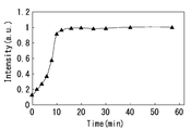
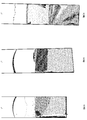
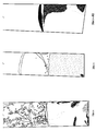
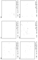
図10は本試験におけるサンプルの波長600nmの蛍光強度の経時変化を示すグラフである。また、図11及び図12は写真データ、図13は、1000倍のSEM画像、図14は、30000倍のSEM画像である。
以下の条件による硫酸銅めっき処理を行い、めっき皮膜の品質評価を行った。ここでは、上述した実験装置構成7に、硫酸銅めっき液70を充填しためっき漕でめっき処理を行った。めっき処理は、電流密度15.6mA/cm2(電流値0.2A)で、回転子を1,000rpmで回転させながら、30分間行った。硫酸銅めっき液として、通電前(0min)、通電処理を4min、8min、16min、30min行ったもの、および30min通電を行った液に、再度JGBを当所の濃度分追加(補充)したものを用いた。それぞれの液で作製されためっき皮膜部分の写真撮影と、走査型電子顕微鏡(SEM)による観察(1,000倍および30,000倍)を行い、めっき皮膜のざらつき、光沢、色むらを確認した。
図10は本試験におけるサンプルの波長600nmの蛍光強度の経時変化を示すグラフである。また、図11及び図12は写真データ、図13は、1000倍のSEM画像、図14は、30000倍のSEM画像である。
図11及び図12に示すように、通電前(0min)のサンプルは、表面にざらつきが少しあり、半光沢が見られた。4minの表面は色むらが生じていた。8minの表面は全体的に白いざらつきに広がりが確認され、半光沢が見られた。16minの表面は全体的に色むらがあり、光沢がなかった。30minの表面は、全体的に白っぽく色むらがあり、光沢がなく、ざらつきがあった。30min後にJGB再添加した表面は、全体的に白っぽく色むらがあり、ざらつきもあるが、半光沢が見られた。図10の蛍光強度の経時変化と比較すると、4min、8minの蛍光強度が著しく増加するタイミングで、表面に色むらが生じ、蛍光強度が最大値となった16minのタイミングでは表面全体に色むらの広がりが確認された。この結果から、蛍光強度の増加と、めっき被膜表面の色むらの広がりに相関が確認された。
1000倍のSEM画像では各サンプルにおける表面は均一な表面のように見えるが(図13参照)、図14に示す30000倍のSEM画像では、通電前(0min)のサンプルで見られていたきれいな表面が、時間の経過と共に表面上の粒子が大きくなり、凹凸構造が顕著に見られるようになった。また、30min後にJGB再添加した表面は、4minのサンプルの表面と同程度の質感となっていた。
(2)蛍光強度と光散乱強度の同時測定
上述した蛍光強度の測定系に対して、光検出機構に分光測光装置を採用して、同一の硫酸銅めっき液に対して、硫酸銅めっき処理中の蛍光強度と光散乱強度の測定を行った。図15の符号Sに示すように、光散乱強度は、波長550nmにピークが確認されるが、これは、光源となる光の波長によるものである。また、図15中の符号Fで示すように、蛍光強度は波長600nm付近にピークが確認される。
上述した蛍光強度の測定系に対して、光検出機構に分光測光装置を採用して、同一の硫酸銅めっき液に対して、硫酸銅めっき処理中の蛍光強度と光散乱強度の測定を行った。図15の符号Sに示すように、光散乱強度は、波長550nmにピークが確認されるが、これは、光源となる光の波長によるものである。また、図15中の符号Fで示すように、蛍光強度は波長600nm付近にピークが確認される。
図16に示すように、通電開始から時間経過ごとに、蛍光強度(符号F)と光散乱強度(符号S)を計測することで、通電時間に伴う変化が見られる。通電開始から初期の段階では、蛍光強度が顕著に増加して、この変化を計測することで、正常な状態のめっき被膜表面(符号X1の領域)から、めっき被膜の表面のむらの発生、広がり(符号X2の領域)を予測することができる。更に、蛍光強度が増加するタイミングの途中から、光散乱強度が増加していき、この変化を計測することで、光散乱強度の増加と相関するめっき被膜の荒れを予測することができる。このように、同一のめっき槽において、通電処理の時間経過に伴い生じる「被膜のむら」と「被膜の荒れ」という2つの異なるめっき被膜の品質指標を、蛍光強度と光散乱強度を測定することで簡易に予測することができる。なお、符号Iは、めっき被膜における荒れのファクターの増加を概念的に示した矢印である。s
1 硫酸銅めっき液の評価機構
2 めっき槽
20 硫酸銅めっき液
21 ビーカー
22 固定治具
23 ノズル
24 電源
25 陰極
26 陽極
3 光源
4 ライトチョッパ
5 レンズ
6 光検出機構
61 フォトマル
62 ロックインアンプ
63 端末
2 めっき槽
20 硫酸銅めっき液
21 ビーカー
22 固定治具
23 ノズル
24 電源
25 陰極
26 陽極
3 光源
4 ライトチョッパ
5 レンズ
6 光検出機構
61 フォトマル
62 ロックインアンプ
63 端末
Claims (6)
- 添加剤を含有するめっき液を用いためっきの被めっき対象物について、少なくとも被膜のむらを検知するために、前記めっき液に所定の波長の光を照射する工程を備える
めっき液の評価方法。 - 前記添加剤は少なくともアゾ基を有する色素分子を含む
請求項1に記載のめっき液の評価方法。 - 前記被めっき対象物について、被膜のむらに加えて被膜の荒れを検知するために、前記めっき液に所定の波長の光を照射する
請求項1又は請求項2に記載のめっき液の評価方法。 - 前記所定の波長の光の照射は、前記めっき液に通電して、被めっき対象物にめっきをしながら行う
請求項1、請求項2又は請求項3に記載のめっき液の評価方法。 - 添加剤を含有するめっき液が充填されためっき槽を有するめっき装置と、
前記めっき液に所定の波長の光を照射可能な光源発生手段とを備える
めっき液の評価機構。 - 前記光源発生手段は、前記所定の波長の光の照射位置を可変可能に構成された
請求項5に記載のめっき液の評価機構。
Applications Claiming Priority (2)
| Application Number | Priority Date | Filing Date | Title |
|---|---|---|---|
| JP2017-138579 | 2017-07-14 | ||
| JP2017138579A JP2020152927A (ja) | 2017-07-14 | 2017-07-14 | めっき液の評価方法及びめっき液の評価機構 |
Publications (1)
| Publication Number | Publication Date |
|---|---|
| WO2019013002A1 true WO2019013002A1 (ja) | 2019-01-17 |
Family
ID=65002564
Family Applications (1)
| Application Number | Title | Priority Date | Filing Date |
|---|---|---|---|
| PCT/JP2018/024540 Ceased WO2019013002A1 (ja) | 2017-07-14 | 2018-06-28 | めっき液の評価方法及びめっき液の評価機構 |
Country Status (2)
| Country | Link |
|---|---|
| JP (1) | JP2020152927A (ja) |
| WO (1) | WO2019013002A1 (ja) |
Citations (2)
| Publication number | Priority date | Publication date | Assignee | Title |
|---|---|---|---|---|
| US20030049850A1 (en) * | 2001-09-12 | 2003-03-13 | Golden Josh H. | Enhanced detection of metal plating additives |
| JP2013053338A (ja) * | 2011-09-02 | 2013-03-21 | Sumitomo Metal Mining Co Ltd | 硫酸銅めっき液中の染料系添加剤の濃度測定方法、めっき方法及びめっき装置 |
-
2017
- 2017-07-14 JP JP2017138579A patent/JP2020152927A/ja active Pending
-
2018
- 2018-06-28 WO PCT/JP2018/024540 patent/WO2019013002A1/ja not_active Ceased
Patent Citations (2)
| Publication number | Priority date | Publication date | Assignee | Title |
|---|---|---|---|---|
| US20030049850A1 (en) * | 2001-09-12 | 2003-03-13 | Golden Josh H. | Enhanced detection of metal plating additives |
| JP2013053338A (ja) * | 2011-09-02 | 2013-03-21 | Sumitomo Metal Mining Co Ltd | 硫酸銅めっき液中の染料系添加剤の濃度測定方法、めっき方法及びめっき装置 |
Also Published As
| Publication number | Publication date |
|---|---|
| JP2020152927A (ja) | 2020-09-24 |
Similar Documents
| Publication | Publication Date | Title |
|---|---|---|
| KR20020034894A (ko) | 도금조 분석 방법 | |
| JPS6019455B2 (ja) | 有機レベリング剤の有効量を決定する方法 | |
| CN1213295C (zh) | 测量电镀浴中的添加剂浓度 | |
| CN108760821B (zh) | 一种电镀添加剂的定性和定量分析方法 | |
| KR20050111766A (ko) | 전기 구리 도금액의 분석 방법, 그 분석 장치 및 반도체제품의 제조 방법 | |
| TWI275790B (en) | Analysis method | |
| US6508924B1 (en) | Control of breakdown products in electroplating baths | |
| Hermanns et al. | In-situ control of microdischarge characteristics in unipolar pulsed plasma electrolytic oxidation of aluminum | |
| US7384535B2 (en) | Bath analysis | |
| Ackermann et al. | A complementary Raman and SECM study on electrically conductive coatings based on graphite sol-gel composite electrodes for the electrochemical antifouling | |
| Zhu et al. | Interaction between PCB-Cu corrosion and electrochemical migration under the Coupling of electric field and thin liquid film | |
| US4939370A (en) | Method of and device for inspecting and/or controlling metallization processes | |
| JP2020152927A (ja) | めっき液の評価方法及びめっき液の評価機構 | |
| Sciscenko et al. | Determination of a typical additive in zinc electroplating baths | |
| US11125717B2 (en) | Electrochemical sensor for lead detection | |
| JP7291911B2 (ja) | 電気ニッケルめっき液中の添加剤濃度推定方法 | |
| US12241862B2 (en) | Electrochemical sensor for lead detection | |
| Xu et al. | Study on the preparation mechanism and property analysis of a localized Au coating by laser-induced cyanide-free electroplating | |
| JP6011874B2 (ja) | めっき液に含まれる抑制剤の評価方法 | |
| Li et al. | Toward Preeminent Throwing Power from a Novel Alkaline Copper Electronic Electroplating Bath with Composite Coordination Agents | |
| JP2013053338A (ja) | 硫酸銅めっき液中の染料系添加剤の濃度測定方法、めっき方法及びめっき装置 | |
| JP2009242876A (ja) | めっきつきまわり評価装置および評価方法 | |
| Yang et al. | Effect of power supply on the deposition of Zn on a steel substrate using cathodic plasma electrolysis | |
| WO2014094810A1 (en) | Method for monitoring the filling properties of a copper electrolyte | |
| US20020084195A1 (en) | Automated chemical management system executing improved electrolyte analysis method |
Legal Events
| Date | Code | Title | Description |
|---|---|---|---|
| 121 | Ep: the epo has been informed by wipo that ep was designated in this application |
Ref document number: 18831021 Country of ref document: EP Kind code of ref document: A1 |
|
| NENP | Non-entry into the national phase |
Ref country code: DE |
|
| 122 | Ep: pct application non-entry in european phase |
Ref document number: 18831021 Country of ref document: EP Kind code of ref document: A1 |
|
| NENP | Non-entry into the national phase |
Ref country code: JP |