WO2019012764A1 - 電極装置 - Google Patents
電極装置 Download PDFInfo
- Publication number
- WO2019012764A1 WO2019012764A1 PCT/JP2018/015076 JP2018015076W WO2019012764A1 WO 2019012764 A1 WO2019012764 A1 WO 2019012764A1 JP 2018015076 W JP2018015076 W JP 2018015076W WO 2019012764 A1 WO2019012764 A1 WO 2019012764A1
- Authority
- WO
- WIPO (PCT)
- Prior art keywords
- electrode
- terminal
- installation terminal
- installation
- signal
- Prior art date
- Legal status (The legal status is an assumption and is not a legal conclusion. Google has not performed a legal analysis and makes no representation as to the accuracy of the status listed.)
- Ceased
Links
Images






Classifications
-
- H—ELECTRICITY
- H04—ELECTRIC COMMUNICATION TECHNIQUE
- H04B—TRANSMISSION
- H04B13/00—Transmission systems characterised by the medium used for transmission, not provided for in groups H04B3/00 - H04B11/00
- H04B13/005—Transmission systems in which the medium consists of the human body
-
- H—ELECTRICITY
- H04—ELECTRIC COMMUNICATION TECHNIQUE
- H04W—WIRELESS COMMUNICATION NETWORKS
- H04W76/00—Connection management
- H04W76/10—Connection setup
Definitions
- the present disclosure relates to an electrode device.
- the human body communication system is configured of a plurality of terminals in proximity to the user's human body.
- Each terminal has at least two electrodes, and when the terminal worn by the user causes a potential difference between the two electrodes, an electric field distribution is generated on the surface of the human body of the user.
- the contact between the user having the electric field distribution and the other terminal or the spatial coupling between the terminals causes a potential difference between the two electrodes of the other terminal, and the other terminal extracts a signal from the potential difference, Human body communication (electric field communication) can be realized.
- Patent Document 1 discloses a gate system using human body communication.
- the electrode installed at the gate and the portable terminal carried by the user communicate via spatial coupling, and the user is authenticated based on the communication.
- the present disclosure proposes a new and improved electrode device capable of suppressing the occurrence of communication unintended by the user.
- a first electrode and a second electrode are provided, and the second electrode is a region facing one surface of the first electrode, and the other of the first electrode.
- An electrode device is provided, which has a region projecting on the side of the surface.
- FIG. 2 shows a top view and a cross-sectional view of the installation terminal according to the first embodiment. It is an explanatory view showing an installation terminal by a 1st embodiment. It is explanatory drawing which shows simulation of the sensitivity with respect to each direction of the installation terminal by 1st Embodiment. It is explanatory drawing which shows the installation terminal by 2nd Embodiment.
- a plurality of components having substantially the same functional configuration may be distinguished by attaching different alphabets to the same reference numerals.
- each of the plurality of components is only given the same reference numeral.
- BAN communication human body communication
- BAN communication human body communication
- an electrode provided on the terminals distributing an electric field on the surface of the human body.
- FIG. 1 is an explanatory view showing a configuration of a human body communication system.
- a human body communication system including the installation terminal 10 and the wearable terminal 20 is shown.
- the installation terminal 10 is an example of an electrode device having at least two electrodes, and in the example shown in FIG. 1, the installation terminal 10 is installed at a door D of a building H.
- the installation terminal 10 also includes a communication processing unit such as a reception processing unit that extracts a reception signal from a potential difference generated between two electrodes, and a transmission processing unit that generates a potential difference between the two electrodes as a signal transmission process.
- the method of human body communication is not particularly limited, and for example, the standard of ISO / IEC 17982 (Close Capacitive Coupling Communication, CCCC) may be applied.
- the wearable terminal 20 is a wristband communication device.
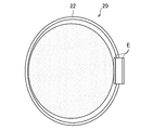
- the wearable terminal 20 includes, as shown in FIG. 2, a band 22 and two electrodes E attached to a wrist or an arm.
- BAN communication using the electrode E is realized by causing the electrode E to generate an electric field in the human body or inducing a reception signal indicating the change in the electric field generated in the human body to the electrode E.
- the two electrodes E are typically formed of parallel flat plates.
- the size of the two electrodes E may be the same or different.
- the central axis of each of the two electrodes E may be the same or different.
- the shape of the electrode E is not particularly limited.
- the shape of the electrode E may be rectangular, circular, or a more complicated shape.
- the wearable terminal 20 is only an example of a communication device, and a portable terminal carried by a user can also be applied as the communication device.
- the method of human body communication is not particularly limited, and, for example, the standard of ISO / IEC 17982 (Close Capacitive Coupling Communication, CCCC) may be applied.
- BAN communication between the wearable terminal 20 and the installation terminal 10 is realized via the user's human body. If the predetermined communication sequence is successful by the BAN communication, the installation terminal 10 controls the locking or unlocking of the key of the door D by, for example, driving an actuator (not shown).
- the wearable terminal 20 when the wearable terminal 20 generates an electric field in the human body, a space electric field is formed around it. Therefore, even if the user does not touch the electrode of the installation terminal 10, when the user approaches the installation terminal 10, the wearable terminal 20 and the installation terminal 10 can be spatially coupled. As a result, BAN communication is performed between the wearable terminal 20 and the installation terminal 10, and locking or unlocking of the door D is performed.
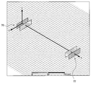
- FIG. 3 is an explanatory view showing an arrangement example of two sets of electrodes.
- the receiving electrode 70 and the transmitting electrode 72 are shown, and the transmitting electrode 72 is located on the normal direction of the plane of the receiving electrode 70.
- the transmitting electrode 72 shown in FIG. 3 is 0 deg (front)
- the transmitting electrode 72 rotationally moves within the range of 0 deg to 360 deg around the z axis shown in FIG.
- the signal strength of the received signal changes as shown in FIG.
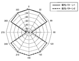
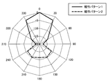
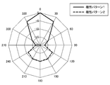
- FIG. 4 is an explanatory view showing the signal strength at the receiving electrode 70 of the signal transmitted from each rotational position. Numbers such as “ ⁇ 10” and “ ⁇ 20” in FIG. 4 indicate dB values of sensitivity in each direction based on the sensitivity to 0 deg. As shown in FIG. 4, the signal strength at the receiving electrode 70 of the signals transmitted from 0 deg and 180 deg is maximum. The receiving electrode 70 has sufficient sensitivity to the signal transmitted from the wide angle range including 0 deg and 180 deg. In FIG. 4, the solid line indicates the polarity pattern 1 and the broken line indicates the polarity pattern 2. The polar pattern 1 and the polar pattern 2 have mutually opposite polarity patterns. A signal transmitted from the front side of the receiving electrode 70 has a polarity pattern 1, and a signal transmitted from the back side of the receiving electrode 70 has a polarity pattern 2.
- the receiving electrode 70 is equivalent to the signal transmitted from the outside (for example, 0 deg) of the building H and the signal transmitted from the inside (for example, 180 deg) of the building H Have a sensitivity of Therefore, even if the user wearing the wearable terminal 20 approaches the installation terminal from either the outside or the inside of the building H, the installation terminal and the wearable terminal 20 can be spatially coupled.
- the signal is a signal transmitted from the outside or the inside of the building H based on the polarity pattern of the signal received by the receiving electrode 70.
- the reception electrode 70 has reception sensitivity in a wide angle range, it is difficult to determine the position of the transmission source of the signal with high accuracy using only the polarity pattern.
- the inventor of the present invention has come to create an embodiment of the present disclosure paying attention to the above circumstances. According to the embodiment of the present disclosure, it is possible to determine the positional relationship between the installation terminal 10 and the wearable terminal 20 with high accuracy, and as a result, it is possible to suppress the occurrence of communication not intended by the user.
- the installation terminal 11 according to the first embodiment, the installation terminal 12 according to the second embodiment, the installation terminal 13 according to the third embodiment, and the installation terminal 14 according to the fourth embodiment will be sequentially described in detail below.
- the term “installation terminal 10” is used as a concept encompassing the installation terminals 11 to 14 according to each embodiment.
- FIG. 5 is a perspective view of the installation terminal 11 according to the first embodiment.
- FIG. 6 is a top view and a cross-sectional view of the installation terminal 11 according to the first embodiment.
- the installation terminal 11 includes the flat plate electrode 110 (first electrode), the square electrode 120 (second electrode), and the control substrate 130. .
- the flat plate electrode 110 is a conductor disposed inside the square electrode 120 as shown in FIGS. 5 and 6.
- the flat electrode 110 has an upper surface 111 and a lower surface 112.
- the upper surface 111 and the lower surface 112 may be, for example, a square having a side length of 30 mm, as shown in the top view of FIG.
- the rectangular electrode 120 is a rectangular conductor having a bottom surface 121, a side surface 123 perpendicular to the bottom surface 121, and a top surface 125 facing the bottom surface 121.
- the bottom surface 121 is a region facing the lower surface 112 of the flat plate electrode 110.
- the side surface 123 and the top surface 125 are regions projecting from the bottom surface 121 to the top surface 111 side of the flat plate electrode 110.
- the upper surface 125 of the rectangular electrode 120 is a surface facing the upper surface 111 of the flat plate electrode 110, and has an opening 127 at the center.
- the bottom surface 121 may be, for example, a square having a side length of 67 mm, and the side surface 123 may have a height of 38 mm.
- the opening 127 may be a square having a side length of 25 mm, and the difference in height between the flat plate electrode 110 and the upper surface 125 of the rectangular electrode 120 may be 15 mm.
- the flat plate electrode 110 and the side surface 123 of the rectangular electrode 120 have a space, that is, the area of the flat plate electrode 110 is smaller than the area of the bottom surface 121 of the square electrode 120. Further, the lower surface 112 of the flat plate electrode 110 and the bottom surface 121 of the rectangular electrode 120 have a space.
- the rectangular electrode 120 and the flat electrode 110 may be made of, for example, copper.
- the control substrate 130 is configured to perform signal processing for BAN communication, and is electrically connected to the flat plate electrode 110 and the rectangular electrode 120.
- the control board 130 has, for example, a central processing unit (CPU), a modulation / demodulation unit (PHY, MAC), a transmission processing unit, a reception processing unit, and the like.
- the modulation / demodulation unit modulates transmission data supplied from the CPU to generate a modulation signal, and the transmission processing unit applies the modulation signal to the flat plate electrode 110 and the rectangular electrode 120 in a predetermined frequency band to transmit the signal. To be realized.
- the signal input from the flat plate electrode 110 and the rectangular electrode 120 is subjected to amplification processing, band limitation processing for extracting a necessary frequency band, and the like, and the modem unit demodulates reception data from the signal after reception processing.
- reception of a signal is realized.
- control substrate 130 determines whether the signal strength of a signal received from another electrode device such as the wearable terminal 20 exceeds a threshold, and outputs a control signal according to the determination result. Include functions as a control unit.
- the control board 130 outputs a control signal for unlocking or locking the door D in accordance with the determination result.
- the installation terminal 11 as described above is installed in the door D such that the opening 127 faces the outside of the building H.
- the installation terminal 11 installed at the door D has a stronger sensitivity to the signal transmitted from the outside of the building H than to the signal transmitted from the inside of the building H. This is based on the rectangular electrode 120 having a region projecting to the upper surface 111 side of the flat plate electrode 110.
- the above-described region of the rectangular electrode 120 between the wearable terminal 20 and the flat electrode 110 By interposing the bottom surface 121 or the like, a potential difference is unlikely to occur between the flat plate electrode 110 and the rectangular electrode 120.
- the flat plate electrode 110 and the wearable terminal 20 are not shielded by the square electrode 120 due to the presence of the opening 127. A potential difference is likely to occur between the flat plate electrode 110 and the rectangular electrode 120.
- the installation terminal 11 installed at the door D has a higher sensitivity to the signal transmitted from the outside of the building H than to the signal transmitted from the inside of the building H .
- the sensitivities of the installation terminal 11 in each direction will be specifically described.
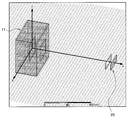
- FIG. 7 is a perspective view of the installation terminal 11, and FIG. 8 is an explanatory view showing simulation of the sensitivity of the installation terminal 11 in each direction.
- the normal direction (x direction, front direction) of the flat plate electrode 110 from the flat plate electrode 110 to the opening 127 shown in FIG. 7 is 0 deg
- the wearable terminal 20 rotationally moves within the range of 0 deg to 360 deg around the z axis
- the signal strength of the signal received by the installation terminal 11 from the wearable terminal 20 changes as shown in FIG. Numbers such as "-5" and "-10" in FIG. 8 indicate dB values of sensitivity in each direction based on the sensitivity to 0 deg.
- the sensitivity of the installation terminal 11 is significantly higher than 90 deg to 270 deg at 0 to 90 deg and 270 to 0 deg. That is, the installation terminal 11 has higher sensitivity to the signal from the outside of the building H than to the signal from the inside of the building H. Further, comparing FIG. 4 and FIG. 8, in the example of FIG. 4, the sensitivity exists in the range of about 120 deg on the front side, but the range in which the installation terminal 11 according to the present embodiment has sensitivity is shown in FIG. The front side is limited to about 60 deg.
- control board 130 of the installation terminal 11 determines whether the signal strength of the signal received from the wearable terminal 20 exceeds the threshold, and the signal strength of the signal received from the wearable terminal 20 exceeds the threshold. When the authentication is successful, a control signal for unlocking or locking the door D is output. If the signal strength of the signal received from the wearable terminal 20 is equal to or less than the threshold, the control board 130 may discard the signal.
- the installation terminal 11 according to the present embodiment communicates with the wearable terminal 20 of the user who approaches the door D from the outside of the building H via the spatial coupling, the wearable of the user who approaches the door D from the inside of the building H Communication with the terminal 20 is difficult. For this reason, it is possible to suppress the case where unlocking or locking of the door D unintended by the user is performed when the user wearing the wearable terminal 20 approaches the door D from the inside of the building H.
- control substrate 130 is based on the fact that the signal strength of the signal received from wearable terminal 20 exceeds the threshold and the signal received from wearable terminal 20 has a predetermined polarity pattern (polarity pattern 1).
- the communication with the wearable terminal 20 may be controlled. With this configuration, it is possible to more reliably prevent the connection between the wearable terminal 20 located inside the building H and the installation terminal 11 from being established.
- FIG. 9 is an explanatory view showing the installation terminal 12 according to the second embodiment.
- the installation terminal 12 according to the second embodiment does not have a surface facing the upper surface 111 of the flat plate electrode 110. That is, the installation terminal 12 has an opening wider than the opening 127 described in the first embodiment.
- the sensitivity of the installation terminal 12 is higher than 90 deg to 270 deg at 0 to 90 deg and 270 to 0 deg, similarly to the simulation result of the first embodiment described with reference to FIG. Become. Furthermore, the sensitivity at 60 deg and 300 deg is higher than the sensitivity shown in the simulation results of the first embodiment. That is, the range in which the installation terminal 12 according to the second embodiment has sensitivity is wider than the range in which the installation terminal 11 according to the first embodiment has sensitivity.
- Such an installation terminal 12 may function more usefully than the installation terminal 11 according to the first embodiment, depending on the characteristics of the door D and the building H on which the installation terminal 12 is installed, or the required security, etc. It is possible.
- FIG. 11 is an explanatory view showing the installation terminal 13 according to the third embodiment.
- the installation terminal 13 according to the third embodiment differs from the installation terminal 11 according to the first embodiment in terms of height (a length between the bottom surface 121 and the top surface 125).
- the height of the installation terminal 13 according to the third embodiment is larger than the height of the installation terminal 11 according to the first embodiment.
- the height of the installation terminal 13 according to the third embodiment is 60 mm.
- the installation terminal 13 When the normal direction (x direction, front direction) of the flat plate electrode 110 from the flat plate electrode 110 to the opening 127 is 0 deg, and the wearable terminal 20 rotationally moves within the range of 0 deg to 360 deg around the z axis, the installation terminal 13 The signal strength of the signal received from the wearable terminal 20 changes as shown in FIG.
- the range in which the installation terminal 13 has sensitivity is narrower than the range in which the installation terminal 11 according to the first embodiment has sensitivity, as shown in FIG. That is, the installation terminal 13 according to the third embodiment can further restrict the range of the wearable terminal 20 capable of establishing a connection with the installation terminal 13.
- the difference between the heights of the flat plate electrode 110 and the upper surface 125 of the installation terminal 10 increases as the height of the installation terminal 10 increases. It can be understood that the larger the installation terminal 10 has sensitivity, the smaller the range of the sensitivity. In view of the fact that the range of sensitivity in the configuration of the installation terminal 11 according to the first embodiment is narrower than the example shown in FIG. 4, the height of the installation terminal 10 is the same as that of the installation terminal 11 according to the first embodiment. The height is 38 mm or more, and the difference in height between the flat plate electrode 110 and the upper surface 125 of the installation terminal 10 is preferably 15 mm or more in the first embodiment. More desirably, the height of the installation terminal 10 may be 60 mm or more, which is the height of the installation terminal 13 according to the first embodiment.
- FIG. 13 is an explanatory view showing the installation terminal 14 according to the fourth embodiment.
- the installation terminal 14 according to the fourth embodiment differs from the installation terminal 12 according to the second embodiment with respect to the height (the length from the bottom surface 121 of the side surface 123).
- the height of the installation terminal 14 according to the fourth embodiment is larger than the height of the installation terminal 12 according to the first embodiment.
- the installation terminal 14 wears
- the signal strength of the signal received from the terminal 20 changes as shown in FIG.
- the range in which the installation terminal 14 has sensitivity is narrower than the range in which the installation terminal 12 according to the second embodiment has sensitivity, as shown in FIG. 14. That is, the installation terminal 14 according to the fourth embodiment can limit the range of the wearable terminal 20 capable of establishing a connection with the installation terminal 14 in comparison with the second embodiment.
- the installation terminal 10 may be installed in a door of a room in the building H.
- the installation terminal 10 may be installed on the door of a vehicle such as a car or a ship.
- the square opening 127 is formed on the upper surface 125 of the installation terminal 11 is described with reference to FIG. 6 and the like, but the configuration of the opening 127 is the same as the example illustrated in FIG. It is not limited.
- the upper surface 125a and the upper surface 125b may be separated, and as a result, a rectangular opening 128 may be formed.
- the sensitivity is relatively wide on the circumference having the axis in the short side direction of the opening 128 as the rotation axis (y axis), and the circumference having the axis in the longitudinal direction of the opening 128 as the rotation axis (z axis) Above it is possible to limit the range of sensitivity.
- the shape of the installation terminal 10 is not limited to square shape.
- the installation terminal 10 may have a cylindrical shape or a spherical shape.
- a first electrode, A second electrode, Equipped with An electrode device comprising: a region facing the one surface of the first electrode; and a region protruding toward the other surface of the first electrode.
- the electrode device according to (1), wherein the region projecting to the other surface side includes a region facing the other surface of the first electrode.
- the electrode device according to (2), wherein the region facing the other surface has an opening.
- the second electrode has a rectangular shape, has a bottom surface as a region facing one surface of the first electrode, and includes a side surface including a region projecting to the other surface of the first electrode.
- the electrode device further includes a control unit configured to control connection establishment based on the fact that the signal strength of a signal received from another electrode device exceeds a threshold value.
- the electrode apparatus as described in a term.
- the control unit is configured such that the signal strength of a signal received from the other electrode device exceeds a threshold, and the connection is performed based on the signal received from the other electrode device having a predetermined polarity pattern.
Landscapes
- Engineering & Computer Science (AREA)
- Computer Networks & Wireless Communication (AREA)
- Signal Processing (AREA)
- Near-Field Transmission Systems (AREA)
- Quality & Reliability (AREA)
- Physics & Mathematics (AREA)
- Electromagnetism (AREA)
Abstract
【課題】ユーザが意図しない通信の発生を抑制する。 【解決手段】第1の電極と、第2の電極と、を備え、前記第2の電極は、前記第1の電極の一方の面と対向する領域、および前記第1の電極の他方の面側に突出する領域を有する、電極装置。
Description
本開示は、電極装置に関する。
近年、BAN(Body Area Network)とも呼ばれる人体通信システムの研究が進められている。人体通信システムは、ユーザの人体に近接する複数の端末により構成される。各端末は少なくとも2枚の電極を有し、ユーザに装着された端末が2枚の電極間に電位差を生じさせると、ユーザの人体表面に電界分布が生じる。電界分布を有するユーザと他の端末との接触、または端末間での空間結合により、他の端末の2枚の電極間に電位差が生じ、他の端末が当該電位差から信号を抽出することで、人体通信(電界通信)が実現され得る。
特許文献1には、人体通信を利用するゲートシステムが開示されている。当該ゲートシステムでは、ゲートに設置された電極とユーザが携帯する携帯端末が空間結合を介して通信し、当該通信に基づいてユーザの認証が行われる。
しかし、人体通信システムにおいては、ユーザが意図しない通信が行われてしまう場合が生じ得た。例えば、家のドアに設置された電極と家の外にいるユーザとの空間結合によりドアの施錠解錠を行うシステムにおいて、家の中にいるユーザがドアに接近した場合に当該ユーザと電極が空間結合し、ユーザが意図しないドアの解錠が行われることが懸念される。
そこで、本開示では、ユーザが意図しない通信の発生を抑制可能な、新規かつ改良された電極装置を提案する。
本開示によれば、第1の電極と、第2の電極と、を備え、前記第2の電極は、前記第1の電極の一方の面と対向する領域、および前記第1の電極の他方の面側に突出する領域を有する、電極装置が提供される。
以上説明したように本開示によれば、ユーザが意図しない通信の発生を抑制することができる。
なお、上記の効果は必ずしも限定的なものではなく、上記の効果とともに、または上記の効果に代えて、本明細書に示されたいずれかの効果、または本明細書から把握され得る他の効果が奏されてもよい。
以下に添付図面を参照しながら、本開示の好適な実施の形態について詳細に説明する。なお、本明細書及び図面において、実質的に同一の機能構成を有する構成要素については、同一の符号を付することにより重複説明を省略する。
また、本明細書及び図面において、実質的に同一の機能構成を有する複数の構成要素を、同一の符号の後に異なるアルファベットを付して区別する場合もある。ただし、実質的に同一の機能構成を有する複数の構成要素の各々を特に区別する必要がない場合、複数の構成要素の各々に同一符号のみを付する。
また、以下に示す項目順序に従って本開示を説明する。
0.人体通信システムの概要
1.第1の実施形態
2.第2の実施形態
3.第3の実施形態
4.第4の実施形態
5.むすび
0.人体通信システムの概要
1.第1の実施形態
2.第2の実施形態
3.第3の実施形態
4.第4の実施形態
5.むすび
<0.人体通信システムの概要>
本開示の実施形態は、BAN(Body Area Network)とも呼ばれる人体通信システムに適用される。人体通信システムにおける端末間のBAN通信(人体通信)は、端末に設けられた電極が人体表面に電界を分布させることにより実現される。以下、図1を参照し、このような人体通信システムの具体的な構成例を説明する。
本開示の実施形態は、BAN(Body Area Network)とも呼ばれる人体通信システムに適用される。人体通信システムにおける端末間のBAN通信(人体通信)は、端末に設けられた電極が人体表面に電界を分布させることにより実現される。以下、図1を参照し、このような人体通信システムの具体的な構成例を説明する。
図1は、人体通信システムの構成を示す説明図である。図1においては、設置端末10およびウェアラブル端末20を含む人体通信システムを示している。
設置端末10は、少なくとも2つの電極を有する電極装置の一例であり、図1に示した例では、建物HのドアDに設置されている。設置端末10は、2つの電極間に生じた電位差から受信信号を抽出する受信処理部、信号の送信処理として2つの電極間に電位差を生じさせる送信処理部、などの通信処理部も備える。人体通信の方式は特に限定されず、例えば、ISO/IEC 17982 (Close Capacitive Coupling Communication ,CCCC)の規格が適用されてもよい。
ウェアラブル端末20は、リストバンド型の通信装置である。ウェアラブル端末20は、図2に示すように、手首または腕に装着されるバンド部22および2枚の電極Eを備える。電極Eが人体に電界を生じさせること、または、電極Eに人体に生じた電界の変化を示す受信信号が誘起されることにより、電極Eを用いたBAN通信が実現される。
なお、2枚の電極Eは、典型的には平行平板で構成される。2枚の電極Eのサイズは、同一であってもよいし、異なってもよい。また、2枚の電極Eの各々の中心軸は、同一であってもよいし、異なってもよい。また、電極Eの形状は特に限定されず、例えば、電極Eの形状は矩形であってもよいし、円形であってもよいし、より複雑な形状であってもよい。また、ウェアラブル端末20は通信装置の一例に過ぎず、通信装置として、ユーザによって携帯される携帯端末も適用可能である。また、人体通信の方式は特に限定されず、例えば、ISO/IEC 17982 (Close Capacitive Coupling Communication ,CCCC)の規格が適用されてもよい。
上述したウェアラブル端末20を装着するユーザが設置端末10の電極に触れると、ユーザの人体を介してウェアラブル端末20と設置端末10との間のBAN通信が実現される。BAN通信により所定の通信シーケンスが成功すると、設置端末10は、例えば図示しないアクチュエータを駆動することによりドアDの鍵の施錠または解錠を制御する。
ここで、ウェアラブル端末20が人体に電界を生じさせると、周囲に空間電場が形成される。このため、ユーザが設置端末10の電極に触れなくても、ユーザが設置端末10に近づくことにより、ウェアラブル端末20と設置端末10が空間結合し得る。結果、ウェアラブル端末20と設置端末10との間でBAN通信が行われ、ドアDの施錠または解錠が行われる。
(背景)
しかし、2つの電極が2枚の平行平板で構成される設置端末が用いられる場合、建物Hの内側からウェアラブル端末20を装着したユーザが設置端末に近づくことによってもウェアラブル端末20と設置端末が空間結合し、結果、ユーザが意図しないドアDの施錠または解錠が行われてしまう。以下、この点について図3および図4を参照してより具体的に説明する。
しかし、2つの電極が2枚の平行平板で構成される設置端末が用いられる場合、建物Hの内側からウェアラブル端末20を装着したユーザが設置端末に近づくことによってもウェアラブル端末20と設置端末が空間結合し、結果、ユーザが意図しないドアDの施錠または解錠が行われてしまう。以下、この点について図3および図4を参照してより具体的に説明する。
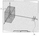
図3は、2組の電極の配置例を示す説明図である。図3においては、受信電極70および送信電極72が示されており、受信電極70の平面の法線方向上に送信電極72が位置している。図3に示した送信電極72の位置を0deg(正面)として、図3に示したz軸周りで送信電極72が0deg~360degの範囲内で回転移動した場合、受信電極70が送信電極72から受信する信号の信号強度は図4に示すように変化する。
図4は、各回転位置から送信された信号の受信電極70における信号強度を示す説明図である。図4における「-10」、「-20」などの数字は、0degへの感度を基準とする各方向への感度のdB値を示す。図4に示したように、0degおよび180degから送信された信号の受信電極70における信号強度は最大となる。受信電極70は、0degおよび180degを含む広角な範囲から送信された信号に対して十分な感度を有する。なお、図4において実線は極性パターン1を示し、破線は極性パターン2を示す。極性パターン1と極性パターン2は相互に反対の極性パターンである。受信電極70の正面側から送信された信号は極性パターン1を有し、受信電極70の背面側から送信された信号は極性パターン2を有する。
上述した受信電極70を有する設置端末においては、受信電極70は、建物Hの外側(例えば、0deg)から送信された信号および建物Hの内側(例えば、180deg)から送信された信号に対して同等の感度を有する。このため、ウェアラブル端末20を装着したユーザが建物Hの外側または内側のいずれから設置端末に近づいても、設置端末とウェアラブル端末20が空間結合し得る。
この点に関し、受信電極70が受信した信号の極性パターンに基づいて、当該信号が建物Hの外側または内側から送信された信号であるかを判断することが考えられる。しかし、受信電極70は広角な範囲に受信感度を有するので、極性パターンのみで信号の送信元の位置を高精度に判断することは困難であった。
そこで、本件発明者は、上記事情に着目して本開示の実施形態を創作するに至った。本開示の実施形態によれば、設置端末10とウェアラブル端末20との位置関係を高精度に判断することが可能となり、結果、ユーザが意図しない通信の発生を抑制することが可能である。以下、第1の実施形態による設置端末11、第2の実施形態による設置端末12、第3の実施形態による設置端末13および第4の実施形態による設置端末14について順次詳細に説明する。なお、本明細書では、各実施形態による設置端末11~14を包括する概念として設置端末10という表現が用いられる。
<1.第1の実施形態>
図5は、第1の実施形態による設置端末11の斜視図である。図6は、第1の実施形態による設置端末11の上面図および断面図である。
図5は、第1の実施形態による設置端末11の斜視図である。図6は、第1の実施形態による設置端末11の上面図および断面図である。
図5および図6に示したように、本実施形態による設置端末11は、平板電極110(第1の電極)と、角型電極120(第2の電極)と、制御基板130と、を備える。
平板電極110は、図5および図6に示したように、角型電極120の内側に配置される導体である。平板電極110は、上面111および下面112を有する。上面111および下面112は、図6の上面図に示したように、例えば1辺の長さが30mmである正方形であってもよい。
角型電極120は、底面121、底面121と垂直な側面123、および底面121と対向する上面125を有する角型形状の導体である。底面121は、平板電極110の下面112と対向する領域である。側面123および上面125は、底面121から平板電極110の上面111側に突出する領域である。また、角型電極120の上面125は、平板電極110の上面111と対向する面であり、中央に開口127を有する。
図6に示したように、底面121は例えば1辺の長さが67mmである正方形であってもよく、側面123の高さは38mmであってもよい。開口127は1辺の長さが25mmである正方形であってもよく、平板電極110と角型電極120の上面125との高さの差分は15mmであってもよい。平板電極110と角型電極120の側面123とは間隔を有する、すなわち、平板電極110の面積は角型電極120の底面121の面積よりも小さい。また、平板電極110の下面112と角型電極120の底面121は間隔を有する。なお、角型電極120および平板電極110は例えば銅で形成され得る。
制御基板130は、BAN通信のための信号処理を行う構成であって、平板電極110および角型電極120と電気的に接続されている。制御基板130は、例えば、CPU(Central Processing Unit)、変復調部(PHY、MAC)、送信処理部、および受信処理部などを有する。変復調部がCPUから供給される送信データを変調して変調信号を生成し、送信処理部が変調信号を所定の周波数帯で平板電極110および角型電極120に印加することにより、信号の送信が実現される。また、平板電極110および角型電極120から入力される信号に増幅、必要な周波数帯域を抜き出すための帯域制限などの受信処理を施し、受信処理後の信号から変復調部が受信データを復調することにより、信号の受信が実現される。
また、本実施形態による制御基板130は、ウェアラブル端末20のような他の電極装置から受信された信号の信号強度が閾値を上回っているか否かを判断し、判断結果に応じた制御信号を出力する制御部としての機能を包含する。例えば、制御基板130は、上記判断結果に応じてドアDの解錠または施錠ための制御信号を出力する。
上述したような設置端末11は、開口127が建物Hの外側を向くようにドアDに設置される。ドアDに設置された設置端末11は、建物Hの外側から送信された信号に対して、建物Hの内側から送信された信号に対するよりも強い感度を有する。これは、角型電極120が、平板電極110の上面111側にまで突出する領域を有することに基づく。
具体的には、平板電極110の下面112側、すなわち建物Hの内側に位置するウェアラブル端末20により形成された空間電場では、ウェアラブル端末20と平板電極110の間に角型電極120の上記領域および底面121などが介在することにより、平板電極110と角型電極120の間に電位差が生じ難い。
一方、平板電極110の上面111側、すなわち建物Hの外側に位置するウェアラブル端末20により形成された空間電場では、開口127の存在により平板電極110とウェアラブル端末20が角型電極120によって遮蔽されないので、平板電極110と角型電極120の間に電位差が生じやすい。
結果、上述したように、ドアDに設置された設置端末11は、建物Hの外側から送信された信号に対して、建物Hの内側から送信された信号に対するよりも強い感度を有することになる。以下、設置端末11の各方向に対する感度について具体的に説明する。
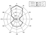
図7は設置端末11の斜視図であり、図8は設置端末11の各方向に対する感度のシミュレーションを示す説明図である。図7に示した平板電極110から開口127へ向かう平板電極110の法線方向(x方向、正面方向)を0degとし、ウェアラブル端末20がz軸周りに0deg~360degの範囲内で回転移動した場合、設置端末11がウェアラブル端末20から受信する信号の信号強度は図8に示すように変化する。図8における「-5」、「-10」などの数字は、0degへの感度を基準とする各方向への感度のdB値を示す。
図8に示したように、設置端末11の感度は、0~90degおよび270~0degにおいて、90deg~270degよりも顕著に高くなる。すなわち、設置端末11は、建物Hの外側からの信号に対して、建物Hの内側からの信号に対してよりも高い感度を有する。また、図4と図8を比較すると、図4の例では正面側の約120degの範囲に感度が存在するが、本実施形態による設置端末11が感度を有する範囲は、図8に示したように正面側の約60degの範囲に制限される。
ここで、設置端末11の制御基板130は、ウェアラブル端末20から受信された信号の信号強度が閾値を上回っているか否かを判断し、ウェアラブル端末20から受信された信号の信号強度が閾値を上回っている場合にウェアラブル端末20との接続確立のための通信(例えば、Association Sequence)を制御し、認証が成功した場合にドアDの解錠または施錠のための制御信号を出力する。ウェアラブル端末20から受信された信号の信号強度が閾値以下である場合、制御基板130は、当該信号を破棄してもよい。
従って、本実施形態による設置端末11は、建物Hの外側からドアDに近づいたユーザのウェアラブル端末20とは空間結合を介して通信するものの、建物Hの内側からドアDに近づいたユーザのウェアラブル端末20とは通信を行い難い。このため、ウェアラブル端末20を装着したユーザが建物Hの内側からドアDに近づくことによりユーザの意図しないドアDの解錠または施錠が行われてしまう場合を抑制することが可能である。
さらに、制御基板130は、ウェアラブル端末20から受信された信号の信号強度が閾値を上回っており、かつ、ウェアラブル端末20から受信された信号が所定の極性パターン(極性パターン1)を有することに基づき、ウェアラブル端末20との通信を制御してもよい。かかる構成により、建物Hの内側に位置するウェアラブル端末20と設置端末11との接続確立をより確実に防止することが可能である。
<2.第2の実施形態>
続いて、本開示の第2の実施形態による設置端末12を説明する。
続いて、本開示の第2の実施形態による設置端末12を説明する。
図9は、第2の実施形態による設置端末12を示す説明図である。図9に示したように、第2の実施形態による設置端末12は、平板電極110の上面111に対向する面を有さない。すなわち、設置端末12は、第1の実施形態で説明した開口127よりも広い開口を有する。
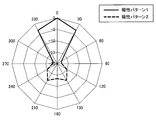
平板電極110から開口へ向かう平板電極110の法線方向(x方向、正面方向)を0degとし、ウェアラブル端末20がz軸周りに0deg~360degの範囲内で回転移動した場合、設置端末11がウェアラブル端末20から受信する信号の信号強度は図10に示すように変化する。
図10に示したように、設置端末12の感度は、図8を参照して説明した第1の実施形態のシミュレーション結果と同様に、0~90degおよび270~0degにおいて、90deg~270degよりも高くなる。さらに、60degおよび300degにおける感度は、第1の実施形態のシミュレーション結果に示される感度よりも高くなる。すなわち、第2の実施形態による設置端末12が感度を有する範囲は、第1の実施形態による設置端末11が感度を有する範囲よりも広くなる。
このような設置端末12は、設置端末12が設置されるドアDおよび建物Hの特性、または求められるセキュリティなどの環境によっては、第1の実施形態による設置端末11よりも有用に機能することが可能である。
<3.第3の実施形態>
続いて、本開示の第3の実施形態による設置端末13を説明する。
続いて、本開示の第3の実施形態による設置端末13を説明する。
図11は、第3の実施形態による設置端末13を示す説明図である。第3の実施形態による設置端末13は、第1の実施形態による設置端末11と、高さ(底面121と上面125との間の長さ)に関して相違する。第3の実施形態による設置端末13の高さは、第1の実施形態による設置端末11の高さよりも大きい。例えば、第3の実施形態による設置端末13の高さは、60mmである。
平板電極110から開口127へ向かう平板電極110の法線方向(x方向、正面方向)を0degとし、ウェアラブル端末20がz軸周りに0deg~360degの範囲内で回転移動した場合、設置端末13がウェアラブル端末20から受信する信号の信号強度は図12に示すように変化する。
設置端末13が感度を有する範囲は、図12に示したように、第1の実施形態による設置端末11が感度を有する範囲よりも狭くなる。すなわち、第3の実施形態による設置端末13は、設置端末13と接続を確立できるウェアラブル端末20の範囲を一層制限することが可能である。
なお、第1の実施形態のシミュレーション結果と、第3の実施形態のシミュレーション結果から、設置端末10の高さが大きいほど、また、平板電極110と設置端末10の上面125との高さの差分が大きいほど、設置端末10が感度を有する範囲を狭くできることが分かる。第1の実施形態による設置端末11の構成で感度の範囲が図4に示した例よりも狭くなっていることに鑑みると、設置端末10の高さは第1の実施形態による設置端末11の高さである38mm以上であり、平板電極110と設置端末10の上面125との高さの差分は第1の実施形態での差分である15mm以上であることが望ましい。さらに望ましくは、設置端末10の高さは第1の実施形態による設置端末13の高さである60mm以上であってもよい。
<4.第4の実施形態>
続いて、本開示の第4の実施形態による設置端末14を説明する。
続いて、本開示の第4の実施形態による設置端末14を説明する。
図13は、第4の実施形態による設置端末14を示す説明図である。第4の実施形態による設置端末14は、第2の実施形態による設置端末12と、高さ(側面123の底面121からの長さ)に関して相違する。第4の実施形態による設置端末14の高さは、第1の実施形態による設置端末12の高さよりも大きい。
平板電極110から開口へ向かう平板電極110の法線方向(x方向、正面方向)を0degとし、ウェアラブル端末20がz軸周りに0deg~360degの範囲内で回転移動した場合、設置端末14がウェアラブル端末20から受信する信号の信号強度は図14に示すように変化する。
設置端末14が感度を有する範囲は、図14に示したように、第2の実施形態による設置端末12が感度を有する範囲よりも狭くなる。すなわち、第4の実施形態による設置端末14は、設置端末14と接続を確立できるウェアラブル端末20の範囲を第2の実施形態より制限することが可能である。
<5.むすび>
以上説明したように、本開示の実施形態によれば、ウェアラブル端末20を装着したユーザが建物Hの内側からドアDに近づくことによりユーザの意図しないドアDの解錠または施錠が行われてしまう場合を抑制することが可能である。
以上説明したように、本開示の実施形態によれば、ウェアラブル端末20を装着したユーザが建物Hの内側からドアDに近づくことによりユーザの意図しないドアDの解錠または施錠が行われてしまう場合を抑制することが可能である。
なお、添付図面を参照しながら本開示の好適な実施形態について詳細に説明したが、本開示の技術的範囲はかかる例に限定されない。本開示の技術分野における通常の知識を有する者であれば、特許請求の範囲に記載された技術的思想の範疇内において、各種の変更例または修正例に想到し得ることは明らかであり、これらについても、当然に本開示の技術的範囲に属するものと了解される。
例えば、上記では建物HのドアDに設置端末10が設置される例を説明したが、設置端末10は、建物H内の部屋のドアに設置されてもよい。また、設置端末10は、自動車や船舶のような乗物のドアに設置されてもよい。
また、第1の実施形態においては、図6などを参照して設置端末11の上面125に正方形の開口127が形成される例を説明したが、開口127の構成は図6に示した例に限定されない。例えば、設置端末11には、図15に示すように上面125aおよび上面125bが分離して構成され、結果、長方形の開口128が形成されてもよい。かかる構成においては、開口128の短手方向の軸を回転軸(y軸)とする周上では比較的広く感度を確保し、開口128の長手方向の軸を回転軸(z軸)とする周上では感度の範囲を制限することが可能である。
また、上記では設置端末10が角型形状を有する例を説明したが、設置端末10の形状は角型形状に限定されない。例えば、設置端末10は円柱形状を有してもよいし、球形状を有してもよい。
また、本明細書に記載された効果は、あくまで説明的または例示的なものであって限定的ではない。つまり、本開示に係る技術は、上記の効果とともに、または上記の効果に代えて、本明細書の記載から当業者には明らかな他の効果を奏しうる。
また、以下のような構成も本開示の技術的範囲に属する。
(1)
第1の電極と、
第2の電極と、
を備え、
前記第2の電極は、前記第1の電極の一方の面と対向する領域、および前記第1の電極の他方の面側に突出する領域を有する、電極装置。
(2)
前記他方の面側に突出する領域は、前記第1の電極の前記他方の面と対向する領域を含む、前記(1)に記載の電極装置。
(3)
前記他方の面と対向する領域は開口を有する、前記(2)に記載の電極装置。
(4)
前記第2の電極は角型形状を有し、前記第1の電極の一方の面と対向する領域として底面を有し、前記第1の電極の他方の面側に突出する領域を含む側面を有する、前記(1)~(3)のいずれか一項に記載の電極装置。
(5)
前記第2の電極の前記底面からの高さは38mm以上であり、
前記第1の電極と、前記側面の前記第1の電極の他方の面側の端との高さの差分は15mm以上である、前記(4)に記載の電極装置。
(6)
前記電極装置は、他の電極装置から受信された信号の信号強度が閾値を上回っていることに基づいて接続確立を制御する制御部をさらに備える、前記(1)~(5)のいずれか一項に記載の電極装置。
(7)
前記制御部は、前記他の電極装置から受信された信号の信号強度が閾値を上回っており、かつ、前記他の電極装置から受信された信号が所定の極性パターンを有することに基づき、前記接続確立を制御する、前記(6)に記載の電極装置。
(1)
第1の電極と、
第2の電極と、
を備え、
前記第2の電極は、前記第1の電極の一方の面と対向する領域、および前記第1の電極の他方の面側に突出する領域を有する、電極装置。
(2)
前記他方の面側に突出する領域は、前記第1の電極の前記他方の面と対向する領域を含む、前記(1)に記載の電極装置。
(3)
前記他方の面と対向する領域は開口を有する、前記(2)に記載の電極装置。
(4)
前記第2の電極は角型形状を有し、前記第1の電極の一方の面と対向する領域として底面を有し、前記第1の電極の他方の面側に突出する領域を含む側面を有する、前記(1)~(3)のいずれか一項に記載の電極装置。
(5)
前記第2の電極の前記底面からの高さは38mm以上であり、
前記第1の電極と、前記側面の前記第1の電極の他方の面側の端との高さの差分は15mm以上である、前記(4)に記載の電極装置。
(6)
前記電極装置は、他の電極装置から受信された信号の信号強度が閾値を上回っていることに基づいて接続確立を制御する制御部をさらに備える、前記(1)~(5)のいずれか一項に記載の電極装置。
(7)
前記制御部は、前記他の電極装置から受信された信号の信号強度が閾値を上回っており、かつ、前記他の電極装置から受信された信号が所定の極性パターンを有することに基づき、前記接続確立を制御する、前記(6)に記載の電極装置。
10~14 設置端末
20 ウェアラブル端末
22 バンド部
110 平板電極
111 上面
112 下面
120 角型電極
121 底面
123 側面
125 上面
127、128 開口
130 制御基板
20 ウェアラブル端末
22 バンド部
110 平板電極
111 上面
112 下面
120 角型電極
121 底面
123 側面
125 上面
127、128 開口
130 制御基板
Claims (7)
- 第1の電極と、
第2の電極と、
を備え、
前記第2の電極は、前記第1の電極の一方の面と対向する領域、および前記第1の電極の他方の面側に突出する領域を有する、電極装置。 - 前記他方の面側に突出する領域は、前記第1の電極の前記他方の面と対向する領域を含む、請求項1に記載の電極装置。
- 前記他方の面と対向する領域は開口を有する、請求項2に記載の電極装置。
- 前記第2の電極は角型形状を有し、前記第1の電極の一方の面と対向する領域として底面を有し、前記第1の電極の他方の面側に突出する領域を含む側面を有する、請求項1に記載の電極装置。
- 前記第2の電極の前記底面からの高さは38mm以上であり、
前記第1の電極と、前記側面の前記第1の電極の他方の面側の端との高さの差分は15mm以上である、請求項4に記載の電極装置。 - 前記電極装置は、他の電極装置から受信された信号の信号強度が閾値を上回っていることに基づいて接続確立を制御する制御部をさらに備える、請求項1に記載の電極装置。
- 前記制御部は、前記他の電極装置から受信された信号の信号強度が閾値を上回っており、かつ、前記他の電極装置から受信された信号が所定の極性パターンを有することに基づき、前記接続確立を制御する、請求項6に記載の電極装置。
Priority Applications (1)
| Application Number | Priority Date | Filing Date | Title |
|---|---|---|---|
| US16/628,118 US20200220625A1 (en) | 2017-07-11 | 2018-04-10 | Electrode device |
Applications Claiming Priority (2)
| Application Number | Priority Date | Filing Date | Title |
|---|---|---|---|
| JP2017135397A JP2019021952A (ja) | 2017-07-11 | 2017-07-11 | 電極装置 |
| JP2017-135397 | 2017-07-11 |
Publications (1)
| Publication Number | Publication Date |
|---|---|
| WO2019012764A1 true WO2019012764A1 (ja) | 2019-01-17 |
Family
ID=65001255
Family Applications (1)
| Application Number | Title | Priority Date | Filing Date |
|---|---|---|---|
| PCT/JP2018/015076 Ceased WO2019012764A1 (ja) | 2017-07-11 | 2018-04-10 | 電極装置 |
Country Status (3)
| Country | Link |
|---|---|
| US (1) | US20200220625A1 (ja) |
| JP (1) | JP2019021952A (ja) |
| WO (1) | WO2019012764A1 (ja) |
Cited By (1)
| Publication number | Priority date | Publication date | Assignee | Title |
|---|---|---|---|---|
| JP2022530215A (ja) * | 2019-09-30 | 2022-06-28 | エルジー・ケム・リミテッド | ホログラフィック光学素子およびその製造方法 |
Citations (6)
| Publication number | Priority date | Publication date | Assignee | Title |
|---|---|---|---|---|
| WO2004010618A1 (ja) * | 2002-07-18 | 2004-01-29 | Ntt Docomo, Inc. | 電界通信システムおよび電界通信装置、および電極配置方法 |
| JP2009302894A (ja) * | 2008-06-13 | 2009-12-24 | Sanyo Electric Co Ltd | 通信システム及びそれに用いられる受信装置 |
| JP2011004177A (ja) * | 2009-06-18 | 2011-01-06 | Nippon Telegr & Teleph Corp <Ntt> | 電界通信用送信モジュール、受信モジュール、トランシーバ及び電界通信システム |
| JP2011097166A (ja) * | 2009-10-27 | 2011-05-12 | Denso Corp | 人体通信用の通信装置 |
| JP2013121034A (ja) * | 2011-12-07 | 2013-06-17 | Toshiba Corp | 通信装置 |
| JP2014060628A (ja) * | 2012-09-18 | 2014-04-03 | Toshiba Corp | 通信装置 |
-
2017
- 2017-07-11 JP JP2017135397A patent/JP2019021952A/ja active Pending
-
2018
- 2018-04-10 US US16/628,118 patent/US20200220625A1/en not_active Abandoned
- 2018-04-10 WO PCT/JP2018/015076 patent/WO2019012764A1/ja not_active Ceased
Patent Citations (6)
| Publication number | Priority date | Publication date | Assignee | Title |
|---|---|---|---|---|
| WO2004010618A1 (ja) * | 2002-07-18 | 2004-01-29 | Ntt Docomo, Inc. | 電界通信システムおよび電界通信装置、および電極配置方法 |
| JP2009302894A (ja) * | 2008-06-13 | 2009-12-24 | Sanyo Electric Co Ltd | 通信システム及びそれに用いられる受信装置 |
| JP2011004177A (ja) * | 2009-06-18 | 2011-01-06 | Nippon Telegr & Teleph Corp <Ntt> | 電界通信用送信モジュール、受信モジュール、トランシーバ及び電界通信システム |
| JP2011097166A (ja) * | 2009-10-27 | 2011-05-12 | Denso Corp | 人体通信用の通信装置 |
| JP2013121034A (ja) * | 2011-12-07 | 2013-06-17 | Toshiba Corp | 通信装置 |
| JP2014060628A (ja) * | 2012-09-18 | 2014-04-03 | Toshiba Corp | 通信装置 |
Cited By (2)
| Publication number | Priority date | Publication date | Assignee | Title |
|---|---|---|---|---|
| JP2022530215A (ja) * | 2019-09-30 | 2022-06-28 | エルジー・ケム・リミテッド | ホログラフィック光学素子およびその製造方法 |
| US12596326B2 (en) | 2019-09-30 | 2026-04-07 | Lg Chem, Ltd. | Holographic optical device and manufacturing method therefor |
Also Published As
| Publication number | Publication date |
|---|---|
| JP2019021952A (ja) | 2019-02-07 |
| US20200220625A1 (en) | 2020-07-09 |
Similar Documents
| Publication | Publication Date | Title |
|---|---|---|
| Haataja et al. | Two practical man-in-the-middle attacks on bluetooth secure simple pairing and countermeasures | |
| EP3352440B1 (en) | Method and apparatus for configuration and control of wireless docking | |
| RU2604953C2 (ru) | Система повышения эффективности у беспроводной стыковочной линии связи | |
| US20160240023A1 (en) | Lock arrangement and method for detecting the presence and location of a device sending a radio signal | |
| Gao et al. | Deaf-aid: Mobile IoT communication exploiting stealthy speaker-to-gyroscope channel | |
| US10560157B2 (en) | Wireless communication system | |
| WO2019012764A1 (ja) | 電極装置 | |
| WO2008142113A1 (de) | Verfahren und vorrichtung zur elektronischen kommunikation zwischen wenigstens zwei kommunikationsgeräten | |
| JP2013125998A (ja) | ループアンテナ | |
| US10411428B2 (en) | Electrical connector | |
| JP5684695B2 (ja) | 無線通信システム | |
| US10107646B2 (en) | Orientation sensor | |
| JP5670976B2 (ja) | 通信装置 | |
| WO2019012778A1 (ja) | 電極装置 | |
| Pozniak et al. | RF exploitation and detection techniques using software defined radio: A survey | |
| WO2011010646A1 (ja) | センサ機能付きrfidタグ | |
| Pasanen et al. | New efficient rf fingerprint-based security solution for bluetooth secure simple pairing | |
| JP5300913B2 (ja) | 設置用電界通信装置 | |
| CN117203101A (zh) | 用于认证使用车辆的人的授权的装置和方法 | |
| JP7653874B2 (ja) | 通信装置 | |
| JP2023042216A (ja) | 通信装置 | |
| JP2018093341A (ja) | アンテナ装置 | |
| JP2021000963A (ja) | 鉄道車両の電気連結器 | |
| US20240397272A1 (en) | Method for operating a smart mobile device, hearing device and hearing system | |
| CN205179095U (zh) | 一种计算机网络安全控制系统 |
Legal Events
| Date | Code | Title | Description |
|---|---|---|---|
| 121 | Ep: the epo has been informed by wipo that ep was designated in this application |
Ref document number: 18832007 Country of ref document: EP Kind code of ref document: A1 |
|
| NENP | Non-entry into the national phase |
Ref country code: DE |
|
| 122 | Ep: pct application non-entry in european phase |
Ref document number: 18832007 Country of ref document: EP Kind code of ref document: A1 |