WO2019008767A1 - 作業車両の制御システム、制御方法、及び作業車両 - Google Patents
作業車両の制御システム、制御方法、及び作業車両 Download PDFInfo
- Publication number
- WO2019008767A1 WO2019008767A1 PCT/JP2017/025022 JP2017025022W WO2019008767A1 WO 2019008767 A1 WO2019008767 A1 WO 2019008767A1 JP 2017025022 W JP2017025022 W JP 2017025022W WO 2019008767 A1 WO2019008767 A1 WO 2019008767A1
- Authority
- WO
- WIPO (PCT)
- Prior art keywords
- work vehicle
- dump
- segments
- candidate positions
- controller
- Prior art date
- Legal status (The legal status is an assumption and is not a legal conclusion. Google has not performed a legal analysis and makes no representation as to the accuracy of the status listed.)
- Ceased
Links
Images



Classifications
-
- E—FIXED CONSTRUCTIONS
- E02—HYDRAULIC ENGINEERING; FOUNDATIONS; SOIL SHIFTING
- E02F—DREDGING; SOIL-SHIFTING
- E02F9/00—Component parts of dredgers or soil-shifting machines, not restricted to one of the kinds covered by groups E02F3/00 - E02F7/00
- E02F9/26—Indicating devices
- E02F9/261—Surveying the work-site to be treated
- E02F9/262—Surveying the work-site to be treated with follow-up actions to control the work tool, e.g. controller
-
- B—PERFORMING OPERATIONS; TRANSPORTING
- B66—HOISTING; LIFTING; HAULING
- B66F—HOISTING, LIFTING, HAULING OR PUSHING, NOT OTHERWISE PROVIDED FOR, e.g. DEVICES WHICH APPLY A LIFTING OR PUSHING FORCE DIRECTLY TO THE SURFACE OF A LOAD
- B66F9/00—Devices for lifting or lowering bulky or heavy goods for loading or unloading purposes
- B66F9/06—Devices for lifting or lowering bulky or heavy goods for loading or unloading purposes movable, with their loads, on wheels or the like, e.g. fork-lift trucks
- B66F9/075—Constructional features or details
- B66F9/12—Platforms; Forks; Other load supporting or gripping members
- B66F9/19—Additional means for facilitating unloading
- B66F9/195—Additional means for facilitating unloading for pushing the load
-
- E—FIXED CONSTRUCTIONS
- E02—HYDRAULIC ENGINEERING; FOUNDATIONS; SOIL SHIFTING
- E02F—DREDGING; SOIL-SHIFTING
- E02F3/00—Dredgers; Soil-shifting machines
- E02F3/04—Dredgers; Soil-shifting machines mechanically-driven
- E02F3/76—Graders, bulldozers, or the like with scraper plates or ploughshare-like elements; Levelling scarifying devices
-
- E—FIXED CONSTRUCTIONS
- E02—HYDRAULIC ENGINEERING; FOUNDATIONS; SOIL SHIFTING
- E02F—DREDGING; SOIL-SHIFTING
- E02F3/00—Dredgers; Soil-shifting machines
- E02F3/04—Dredgers; Soil-shifting machines mechanically-driven
- E02F3/76—Graders, bulldozers, or the like with scraper plates or ploughshare-like elements; Levelling scarifying devices
- E02F3/7609—Scraper blade mounted forwardly of the tractor on a pair of pivoting arms which are linked to the sides of the tractor, e.g. bulldozers
-
- E—FIXED CONSTRUCTIONS
- E02—HYDRAULIC ENGINEERING; FOUNDATIONS; SOIL SHIFTING
- E02F—DREDGING; SOIL-SHIFTING
- E02F3/00—Dredgers; Soil-shifting machines
- E02F3/04—Dredgers; Soil-shifting machines mechanically-driven
- E02F3/76—Graders, bulldozers, or the like with scraper plates or ploughshare-like elements; Levelling scarifying devices
- E02F3/80—Component parts
- E02F3/84—Drives or control devices therefor, e.g. hydraulic drive systems
-
- E—FIXED CONSTRUCTIONS
- E02—HYDRAULIC ENGINEERING; FOUNDATIONS; SOIL SHIFTING
- E02F—DREDGING; SOIL-SHIFTING
- E02F9/00—Component parts of dredgers or soil-shifting machines, not restricted to one of the kinds covered by groups E02F3/00 - E02F7/00
- E02F9/20—Drives; Control devices
- E02F9/2025—Particular purposes of control systems not otherwise provided for
- E02F9/2045—Guiding machines along a predetermined path
-
- G—PHYSICS
- G05—CONTROLLING; REGULATING
- G05D—SYSTEMS FOR CONTROLLING OR REGULATING NON-ELECTRIC VARIABLES
- G05D1/00—Control of position, course, altitude or attitude of land, water, air or space vehicles, e.g. using automatic pilots
- G05D1/02—Control of position or course in two dimensions
- G05D1/021—Control of position or course in two dimensions specially adapted to land vehicles
- G05D1/0212—Control of position or course in two dimensions specially adapted to land vehicles with means for defining a desired trajectory
- G05D1/0217—Control of position or course in two dimensions specially adapted to land vehicles with means for defining a desired trajectory in accordance with energy consumption, time reduction or distance reduction criteria
Definitions
- the present invention relates to a control system, a control method, and a work vehicle of a work vehicle.
- the work performed by the work vehicle is a dumping work in the dumping area.
- the dumping operation is, for example, an operation of transporting an object such as earth and sand excavated in a mine to a cliff in the dumping area and discharging the object below the cliff.
- objects are stacked on the dumping area, and the stacked objects are pushed out of the cliff by a work vehicle such as a bulldozer and dropped below the cliff.
- the total amount of objects piled up in the dumping area often exceeds the maximum capacity of the blades of the work vehicle.
- the shape of the cliff edge is not uniform, the distance between the object and the edge differs depending on the place. Therefore, depending on how the work vehicle is run, work efficiency is affected. If it is a skilled operator, it is acquired by experience how to drive a work vehicle, but it is not easy for an operator with little experience to work efficiently.
- An object of the present invention is to carry out dumping work efficiently and easily by a work vehicle.
- a control system is a control system for a work vehicle for performing a dumping operation for pushing an object from an edge of a damping area, and includes a controller.
- the controller is programmed to perform the following processing.
- the controller obtains damping area data indicating the shape of the edge of the damping area.
- the controller acquires material data indicating the shape of the object in the damping area.
- the controller determines a plurality of segments that partition the object based on the material data.
- the controller determines a plurality of dump candidate positions along the edge of the dumping area.
- the controller determines the dump position in the dump operation by combining the plurality of segments and the plurality of dump candidate positions.
- a control method is a control method of a work vehicle for performing a dumping operation of pushing an object from the edge of a damping area, and includes the following processing.
- the first process is to obtain damping area data indicating the shape of the edge of the damping area.
- the second process is to obtain material data indicating the shape of the object in the damping area.
- the third process is to determine a plurality of segments dividing an object based on material data.
- the fourth process is to determine a plurality of dump candidate positions along the edge of the dumping area.
- the fifth process is to determine a combination of a plurality of segments and a plurality of dump candidate positions.
- the sixth process is to control the work vehicle to perform the dumping work according to the combination.
- an object in the dumping area is divided into a plurality of segments, and a plurality of dump candidate positions are determined along the cliff edge of the dumping area. Then, the dump position is determined by the combination of the plurality of segments and the plurality of dump candidate positions. Therefore, by moving the work vehicle according to the determined dump position, dumping can be performed efficiently and easily.
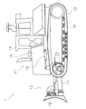
- FIG. 1 is a side view showing a work vehicle 1 according to the embodiment.
- the work vehicle 1 according to the present embodiment is a bulldozer.
- the work vehicle 1 includes a vehicle body 11, a travel device 12, and a work implement 13.
- the vehicle body 11 has a cab 14 and an engine room 15.
- a driver's seat (not shown) is disposed in the driver's cab 14.
- the engine room 15 is disposed in front of the cab 14.
- the traveling device 12 is attached to the lower part of the vehicle body 11.
- the traveling device 12 has a pair of right and left crawler belts 16. In FIG. 1, only the left crawler belt 16 is illustrated. As the crawler 16 rotates, the work vehicle 1 travels.
- the work implement 13 is attached to the vehicle body 11.
- the working machine 13 has a lift frame 17, a blade 18 and a lift cylinder 19.
- the lift frame 17 is attached to the vehicle body 11 so as to be able to move up and down.
- the lift frame 17 supports the blade 18.
- the blade 18 is disposed in front of the vehicle body 11.
- the blade 18 moves up and down as the lift frame 17 moves up and down.
- the lift cylinder 19 is connected to the vehicle body 11 and the lift frame 17.
- the lift frame 17 rotates up and down by the expansion and contraction of the lift cylinder 19.
- FIG. 2 is a block diagram showing the configuration of the drive system 2 of the work vehicle 1 and the control system 3.
- the drive system 2 includes an engine 22, a hydraulic pump 23, and a power transmission 24.
- the hydraulic pump 23 is driven by the engine 22 and discharges hydraulic oil.
- the hydraulic oil discharged from the hydraulic pump 23 is supplied to the hydraulic actuator 25.
- the hydraulic actuator 25 includes the lift cylinder 19 described above. Although one hydraulic pump 23 is illustrated in FIG. 2, a plurality of hydraulic pumps may be provided.
- a control valve 26 is disposed between the hydraulic actuator 25 and the hydraulic pump 23.
- the control valve 26 is a proportional control valve, and controls the flow rate of hydraulic fluid supplied from the hydraulic pump 23 to the lift cylinder 19.
- the control valve 26 may be a pressure proportional control valve.
- the control valve 26 may be an electromagnetic proportional control valve.
- the power transmission 24 transmits the driving force of the engine 22 to the traveling device 12.
- the power transmission device 24 may be, for example, HST (Hydro Static Transmission).
- the power transmission 24 may be, for example, a torque converter or a transmission having a plurality of transmission gears.
- the control system 3 includes a controller 31, a position detection device 32, a communication device 33, and a storage device 34.
- the controller 31 is programmed to control the work vehicle 1 based on the acquired data.
- the controller 31 includes, for example, a processing device such as a CPU.
- the controller 31 is not limited to one unit, but may be divided into a plurality of controllers.
- the position detection device 32 detects the position of the work vehicle 1.
- the position detection device 32 includes, for example, a GNSS (Global Navigation Satellite System) receiver such as a GPS (Global Positioning System).
- the controller 31 acquires current position data indicating the current position of the work vehicle 1 from the position detection device 32.
- GNSS Global Navigation Satellite System
- GPS Global Positioning System
- the communication device 33 is connected to an external device of the work vehicle 1 via a wireless or wired connection.
- the communication device 33 communicates with devices outside the work vehicle 1.
- the communication device 33 communicates with the external surveying device 35.
- the surveying device 35 may be, for example, a device using laser surveying.
- the surveying device 35 may include a camera and survey using image data of a work site.
- the surveying device 35 may be, for example, a device mounted on a UAV (Unmanned Aerial Vehicle) and performing aerial surveys.
- UAV Unmanned Aerial Vehicle
- the storage device 34 includes, for example, a memory and an auxiliary storage device.
- the storage device 34 may be, for example, a RAM or a ROM.
- the storage device 34 may be a semiconductor memory or a hard disk.
- the storage device 34 is an example of a non-transitory computer readable recording medium.
- the storage unit 34 stores computer instructions that can be executed by the processor and control the work vehicle 1.
- the storage device 34 records data from an external device acquired via the communication device 33.
- the controller 31 controls these devices by outputting command signals to the engine 22, the hydraulic pump 23, the power transmission device 24, and the control valve 26.
- the controller 31 operates the hydraulic actuator 25 by controlling the displacement of the hydraulic pump 23 and the opening degree of the control valve 26. Thereby, the working machine 13 can be operated.
- the controller 31 causes the work vehicle 1 to travel by controlling the rotational speed of the engine 22 and the power transmission device 24.
- the controller 31 controls the capacity of the HST hydraulic pump and the capacity of the hydraulic motor.
- the controller 31 controls an actuator for gear shift. Further, the controller 31 turns the work vehicle 1 by controlling the power transmission 24 so that a speed difference is generated between the left and right crawler belts 16.
- the controller 31 can cause the work vehicle 1 to travel automatically by controlling the engine 22 and the power transmission device 24.
- the controller 31 can automatically control the work machine 13 by controlling the engine 22, the hydraulic pump 23, and the control valve 26.
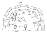
- FIG. 3 is a top view of the damping area.
- FIG. 4 is a side view of the damping area.
- the transport means 100 such as a dump truck transports and discharges an object such as earth and sand to the vicinity of the edge 200 of the cliff.
- piles of piled up objects M1-M6 are placed near the edge 200 of the dumping area.
- the dumping operation is an operation in which the work vehicle 1 cuts a part of the pile of the objects M1 to M6 with the blade 18, and pushes out and drops the edge 200 of the dumping area.
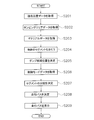
- FIG. 5 is a flowchart showing the process of automatic control of the work vehicle 1. As shown in FIG. 5, in step S101, the controller 31 acquires current position data. The controller 31 acquires current position data from the position detection device 32.
- step S102 the controller 31 acquires damping area data.
- the dumping area data indicates the shape and position of the edge 200 of the dumping area.
- the shape of the damping area is expressed by polygon approximation.
- the surveying apparatus 35 acquires damping area data by surveying the damping area.
- the controller 31 acquires damping area data from the surveying device 35.
- step S103 the controller 31 acquires material data.
- the material data indicates the shape and position of the object M1 in the damping area.
- the shape of the object M1 is expressed by polygon approximation.
- the surveying apparatus 35 acquires material data by surveying the dumping area.
- the controller 31 acquires material data from the surveying device 35.
- step S104 the controller 31 performs segmentation of the object M1.
- the controller 31 determines a plurality of segments SG dividing the object M1 based on the material data.
- the controller 31 calculates the volume of the object M1 based on the material data.
- the controller 31 determines the position of the segment plane SP that is the boundary of the plurality of segments SG such that the volume of each segment SG matches the predetermined target volume. Thereby, as shown in FIG. 7, the controller 31 determines the first to n-th segments SG. In FIG. 7, segment numbers “1” to “n” are assigned to each segment SG.
- the segment plane SP is, for example, along the traveling direction of the work vehicle 1. However, the directions of the segment planes SP may be different from each other.
- the target volume may be determined based on the maximum capacity of the blade 18. For example, the target volume may be the maximum capacity of the blade 18 multiplied by a predetermined percentage.
- step S105 the controller 31 determines a dump candidate position DP.
- the controller 31 determines a plurality of dump candidate positions DP along the edge 200 of the dumping area. For example, the controller 31 determines the positions at constant distances along the edge 200 of the dumping area as dump candidate positions DP. Thereby, as shown in FIG. 7, the controller 31 determines the first to mth dump candidate positions DP. In FIG. 7, dump position numbers “1” to “m” are assigned to each dump candidate position DP.
- the first dump candidate position DP is a position on the edge 200 closest to the first segment SG.
- the number m of dump candidate positions DP may be determined based on the number n of the segments SG.
- the intervals between the plurality of dump candidate positions DP may not be constant.
- control mode data indicates a control mode selected from among a plurality of control modes.
- the control mode may be selected by the operator, for example. Alternatively, it may be selected automatically by the controller 31.
- the requirements considered in determining the combination of the segment SG and the dump candidate position DP are set.
- the plurality of control modes include a shortest distance mode, a uniform distribution mode, and a target distribution mode. The control mode and the requirements will be described later.
- step S107 the controller 31 determines distribution of the segment SG.
- the controller 31 determines a combination of a plurality of segments SG and a plurality of dump candidate positions DP.
- the controller 31 determines a combination of a plurality of segments SG and a plurality of dump candidate positions DP which minimize the cost of dumping, while satisfying the above-described requirements.
- the cost is the movement distance of the work vehicle 1 for transporting the segment SG to the dump candidate position DP.
- the cost may be the distance between the segment SG and the dump candidate position DP. Therefore, the controller 31 determines a combination of a plurality of segments SG and a plurality of dump candidate positions DP which minimize the total movement distance. As described later, in the present embodiment, the controller 31 determines a combination of a plurality of segments SG and a plurality of dump candidate positions DP by linear programming.
- step S108 the controller 31 determines a traveling path.
- the controller 31 determines a traveling path in accordance with the combination of the segment SG determined in step S107 and the dump candidate position DP.
- the controller 31 determines, as the dump position DP, the dump candidate positions DP selected in combination among the plurality of dump candidate positions DP.
- the controller 31 determines the traveling path PH so as to connect the combined segment SG and the dump position DP.
- the traveling path PH only a part of the traveling path is denoted by the symbol “PH”, and the numerals of the other traveling paths are omitted. The same applies to the code "SG" of the segment and the code "DP" of the dump position.
- step S109 the controller 31 controls the work vehicle 1 to execute the dumping work.
- the controller 31 moves the work vehicle 1 along the travel path PH determined in step S108.
- the controller 31 controls the work vehicle 1 based on the current position data and the traveling path PH.
- a combination of the segment SG and the dump candidate position DP is determined using Integer Linear Programming (ILP).
- ILP Integer Linear Programming
- all variables are integers.
- the formula of integer linear programming is shown by the following formula (1). However, It is.
- C is a cost matrix.
- X is a variable matrix.
- a and b are constant matrices which indicate requirements of the variable matrix X.
- the dimension of each matrix is expressed by the following equation (4).
- n is the number of segments SG.
- m is the number of dump candidate positions DP.
- p is the number of requirements.
- the cost matrix C is expressed by the following equations (5) and (6).
- the movement distance from the k-th segment SG to the i-th dump candidate position DP is set as a cost.
- the movement distance is determined, for example, by Euclidean distance. However, the movement distance may be determined by a method other than the Euclidean distance.
- variable matrix X is expressed by the following equations (7) to (9).
- "1” means that the traveling path from the k-th segment SG to the i-th dump candidate position DP is selected, and "0" indicates the k-th segment SG to the i-th dump candidate position DP It means that the traveling path is not selected. That is, the solution of the variable matrix X indicates a combination of the segment SG and the dump candidate position DP.
- FIG. 8 shows an example of the distribution of the segment SG in the shortest distance mode among the control modes described above.
- the number m of dump candidate positions DP is 10, and the number n of segments SG is 10.
- the segment SG and the dump candidate position DP follow the first requirement condition shown by the following equation (10) and minimize the total movement distance.
- the solution of the combination with is determined.
- each of the n segments SG is necessarily transported to any one of the m dump candidate positions DP.
- multiple segments SG may be selected for one dump candidate position DP.
- the third dump candidate position DP is selected for the first and second segments SG.
- the fourth dump candidate position DP is selected for the third and fourth segments SG.
- the fifth dump candidate position DP is selected for the fifth to eighth segments SG.
- the sixth dump candidate position DP is selected for the ninth and tenth segments SG.
- each segment SG is distributed to the closest dump candidate position DP.
- FIG. 9 shows an example of the distribution of the segments SG in the equal distribution mode among the control modes described above.
- the first requirement shown by the equation (10) and the second requirement shown by the following equation (11) are used and the movement distance is
- the solution of the combination of the segment SG and the dump candidate position DP is determined such that the sum is minimized.
- the segment SG of 1 or less is selected for the dump candidate position DP of 1, and the 2 or more segments SG of 1 or more are not selected for the dump position DP of 1 according to the second requirement shown by the equation (11). Therefore, the second requirement shown by the above equation (11) indicates the requirement for equally distributing each segment SG to each dump candidate position DP.
- the first to tenth dump candidate positions DP are selected on a one-to-one basis.
- the segment SG is distributed to the closest dump candidate position DP in the case where each segment SG is equally distributed to each dump candidate position DP.
- the number m of the dump candidate positions DP needs to be equal to or more than the number n of the segments SG, as shown by the following equation (12).
- the number m of dump candidate positions DP and the number n of segments SG are both 10, 10 segments SG are equally distributed to 10 dump candidate positions DP.
- the number m of dump candidate positions DP is larger than the number n of segments SG, there is a dump candidate position DP not selected.
- FIG. 10 shows an example of distribution of the segments SG in the target distribution mode among the control modes described above.
- the first requirement shown in the equation (10) and the third requirement shown in the following equation (13) are followed along with the movement distance.
- the solution of the combination of the segment SG and the dump candidate position DP is determined such that the sum is minimized.
- y i is the number of segments SG distributed to the ith dump candidate position DP.
- V is the total amount of the object M1.
- the number of segments SG distributed to a specific dump candidate position DP is set according to the third requirement shown by equation (13). For example, as shown in FIG. It is. This means that two segments SG are distributed to the first dump candidate position DP. Also, It is. This means that the segment SG is not distributed to the second dump candidate position DP.
- the first and second segments SG are selected for the first dump candidate position DP.
- the third and sixth segments SG are selected for the third dump candidate position DP.
- the fourth and seventh segments SG are selected for the fourth dump candidate position DP.
- the fifth and eighth segments SG are selected for the fifth dump candidate position DP.
- the ninth and tenth segments SG are selected for the tenth dump candidate position DP.
- the segment SG is not distributed to the second, sixth, seventh, eighth and ninth dump candidate positions DP.
- the segment SG is distributed to the closest dump candidate position DP while the number of segments SG distributed to the specific dump candidate position DP is fixed.
- the dump candidate position DP with a smaller amount of soil can be designated to carry the segment SG as compared to other places.
- y i may be set by the operator.
- the controller 31 may determine y i based on the dumping area data.
- the object M1 in the dumping area is divided into a plurality of segments SG, and a plurality of dump candidate positions DP along the cliff edge 200 of the dumping area Is determined. Then, the travel path PH of the work vehicle 1 is determined by the combination of the plurality of segments SG and the plurality of dump candidate positions DP. Therefore, by moving the work vehicle 1 along the travel path PH, dumping can be efficiently performed by automatic control.
- the work vehicle 1 is not limited to the bulldozer but may be another vehicle such as a wheel loader.
- the work vehicle 1 may be a remotely steerable vehicle. In that case, a driver's cab may be omitted like work vehicle 1a shown in FIG. In Drawing 11, the same numerals are given to composition corresponding to work vehicle 1 concerning an embodiment mentioned above.
- a part of control system 3 may be arranged outside work vehicle 1.
- the controller 31 may have a plurality of controllers separate from one another.
- the controller 31 may include a remote controller 311 disposed outside the work vehicle 1 and an on-board controller 312 mounted on the work vehicle 1.
- the remote controller 311 and the on-vehicle controller 312 may be capable of communicating wirelessly via the communication devices 33 and 36. Then, part of the functions of the controller 31 described above may be performed by the remote controller 311, and the remaining functions may be performed by the onboard controller 312.
- the process of determining the combination of the segment SG and the dump candidate position DP (S107) and the process of determining the traveling path PH (S108) are executed by the remote controller 311, and the process of executing the dumping work (S109) It may be performed by the controller 312.
- the automatic control of the work vehicle 1 may be a semi-automatic control performed in conjunction with a manual operation by the operator.
- the automatic control may be a fully automatic control performed without manual operation by the operator.
- the work vehicle 1 may be operated by the operator operating the operation device 37 disposed outside the work vehicle 1. In that case, forward movement, reverse movement, and turning of the work vehicle 1 may be operated by the operation device 37.
- a target point may be set by the operation device 37, and the work vehicle 1 may travel to the target point by automatic control by the controller 31.
- the work vehicle 1 may travel only by the automatic control by the controller 31 without the operation by the operation device 37.
- the dumping area data and the material data may be acquired by separate devices.
- the dumping area data may be obtained from a surveying device outside the work vehicle 1, and the material data may be obtained from another surveying device mounted on the work vehicle 1.
- the dumping work may be performed by the operation of the operator.
- the traveling path PH may be displayed in step S209.
- an example of the travel path PH as shown in FIGS. 8 to 10 may be displayed on the display 38 shown in FIG. 12.
- the processes of steps S201 to S208 are the same as the processes of steps S101 to S108 in FIG. 5, respectively.
- the operating device 37 and the display 38 may be mounted on the work vehicle 1.
- the method of determining the combination of the segment SG and the dump candidate position DP with the lowest cost is not limited to linear programming, and may be another method.
- the cost is not limited to the movement distance, but may be other parameters such as work time or the number of pressings. That is, the combination of the segment SG and the dump candidate position DP may be determined so as to minimize the working time or the number of times of pushing as well as the movement distance.
- the plurality of segments SG may be determined by other methods without being limited to the maximum capacity of the blade.
- the target volume may be a fixed value.
- the target volume may be a variable value according to the state of the work vehicle 1.
- the travel path PH is not limited to a straight line connecting the segment SG and the dump position DP.
- the travel path PH may be determined to minimize the leakage of the object M1 from the blade.
- dumping can be performed efficiently and easily by the work vehicle.
Landscapes
- Engineering & Computer Science (AREA)
- Structural Engineering (AREA)
- Civil Engineering (AREA)
- General Engineering & Computer Science (AREA)
- Mining & Mineral Resources (AREA)
- Mechanical Engineering (AREA)
- Physics & Mathematics (AREA)
- Aviation & Aerospace Engineering (AREA)
- Radar, Positioning & Navigation (AREA)
- Remote Sensing (AREA)
- Transportation (AREA)
- General Physics & Mathematics (AREA)
- Automation & Control Theory (AREA)
- Geology (AREA)
- Life Sciences & Earth Sciences (AREA)
- Operation Control Of Excavators (AREA)
Abstract
Description








200 ダンピングエリアの縁
M1 物体
SG セグメント
DP ダンプ位置
1 作業車両
3 制御システム
18 ブレード
Claims (20)
- ダンピングエリアの縁から物体を押し出すダンプ作業を行うための作業車両の制御システムであって、
コントローラを備え、
前記コントローラは、
前記ダンピングエリアの縁の形状を示すダンピングエリアデータを取得し、
前記ダンピングエリアの前記物体の形状を示すマテリアルデータを取得し、
前記マテリアルデータに基づいて前記物体を区画した複数のセグメントを決定し、
前記ダンピングエリアの縁に沿う複数のダンプ候補位置を決定し、
前記複数のセグメントと前記複数のダンプ候補位置との組み合わせにより、前記ダンプ作業におけるダンプ位置を決定するように、プログラムされている、
作業車両の制御システム。 - 前記コントローラは、前記組み合わせにより、前記ダンプ作業における前記作業車両の走行パスを決定するように、プログラムされている、
請求項1に記載の作業車両の制御システム。 - 前記コントローラは、前記ダンプ作業のコストが最小となる前記複数のセグメントと前記複数のダンプ候補位置との前記組み合わせを決定するようにプログラムされている、
請求項1又は2に記載の作業車両の制御システム。 - 前記コストは、前記作業車両の移動距離であり、
前記コントローラは、前記作業車両の移動距離の総和が最小となる前記複数のセグメントと前記複数のダンプ候補位置との前記組み合わせを決定するようにプログラムされている、
請求項3に記載の作業車両の制御システム。 - 前記コントローラは、線形計画法により前記コストが最小となる前記複数のセグメントと前記複数のダンプ候補位置との前記組み合わせを決定するようにプログラムされている、
請求項3又は4に記載の作業車両の制御システム。 - 前記コントローラは、
前記複数のセグメントと前記複数のダンプ候補位置との前記組み合わせにおいて所定の要求条件を設定し、
前記要求条件を満たしつつ、前記コストが最小となる前記複数のセグメントと前記複数のダンプ候補位置との前記組み合わせを決定する、
請求項3から5のいずれかに記載の作業車両の制御システム。 - 前記要求条件は、前記セグメントのそれぞれに対して選択される前記ダンプ候補位置の数が1つであることを含む、
請求項6に記載の作業車両の制御システム。 - 前記要求条件は、前記ダンプ候補位置のそれぞれに対して選択される前記セグメントの数が1又は0であることを含む、
請求項6又は7に記載の作業車両の制御システム。 - 前記要求条件は、特定の前記ダンプ候補位置に対して2以上の前記セグメントを選択することを含む、
請求項6又は7に記載の作業車両の制御システム。 - 前記作業車両はブレードを備え、
前記コントローラは、前記ブレードの最大容量に基づいて前記複数のセグメントを決定するようにプログラムされている、
請求項1から9のいずれかに記載の作業車両の制御システム。 - 請求項1から10のいずれかに記載の制御システムを備える作業車両。
- ダンピングエリアの縁から物体を押し出すダンプ作業を行うための作業車両の制御方法であって、
前記ダンピングエリアの縁の形状を示すダンピングエリアデータを取得することと、
前記ダンピングエリアの前記物体の形状を示すマテリアルデータを取得することと、
前記マテリアルデータに基づいて前記物体を区画した複数のセグメントを決定することと、
前記ダンピングエリアの縁に沿う複数のダンプ候補位置を決定することと、
前記複数のセグメントと前記複数のダンプ候補位置との組み合わせを決定することと、
前記組み合わせに従って前記ダンプ作業を行うように前記作業車両を制御することと、
を備える作業車両の制御方法。 - 前記ダンプ作業のコストが最小となる前記複数のセグメントと前記複数のダンプ候補位置との前記組み合わせが決定される、
請求項12に記載の作業車両の制御方法。 - 前記コストは、前記作業車両の移動距離であり、
前記作業車両の移動距離の総和が最小となる前記複数のセグメントと前記複数のダンプ候補位置との前記組み合わせが決定される、
請求項13に記載の作業車両の制御方法。 - 線形計画法により前記コストが最小となる前記複数のセグメントと前記複数のダンプ候補位置との前記組み合わせが決定される、
請求項13又は14に記載の作業車両の制御方法。 - 前記複数のセグメントと前記複数のダンプ候補位置との前記組み合わせにおいて所定の要求条件を設定することをさらに備え、
前記要求条件を満たしつつ、前記コストが最小となる前記複数のセグメントと前記複数のダンプ候補位置との前記組み合わせが決定される、
請求項13から15のいずれかに記載の作業車両の制御方法。 - 前記要求条件は、前記セグメントのそれぞれに対して選択される前記ダンプ候補位置の数が1つであることを含む、
請求項16に記載の作業車両の制御方法。 - 前記要求条件は、前記ダンプ候補位置のそれぞれに対して選択される前記セグメントの数が1又は0であることを含む、
請求項16又は17に記載の作業車両の制御方法。 - 前記要求条件は、特定の前記ダンプ位置に対して2以上の前記セグメントを選択することを含む、
請求項16又は17に記載の作業車両の制御方法。 - 前記作業車両は、ブレードを備え、
前記ブレードの最大容量に基づいて前記複数のセグメントが決定される、
請求項12から19のいずれかに記載の作業車両の制御方法。
Priority Applications (5)
| Application Number | Priority Date | Filing Date | Title |
|---|---|---|---|
| US16/335,392 US11035101B2 (en) | 2017-07-07 | 2017-07-07 | Control system for work vehicle, control method, and work vehicle |
| CA3037945A CA3037945C (en) | 2017-07-07 | 2017-07-07 | Control system for work vehicle, control method, and work vehicle |
| PCT/JP2017/025022 WO2019008767A1 (ja) | 2017-07-07 | 2017-07-07 | 作業車両の制御システム、制御方法、及び作業車両 |
| AU2017422760A AU2017422760B2 (en) | 2017-07-07 | 2017-07-07 | Control system for a work vehicle, control method, and work vehicle |
| JP2019528324A JP6861814B2 (ja) | 2017-07-07 | 2017-07-07 | 作業車両の制御システム、制御方法、及び作業車両 |
Applications Claiming Priority (1)
| Application Number | Priority Date | Filing Date | Title |
|---|---|---|---|
| PCT/JP2017/025022 WO2019008767A1 (ja) | 2017-07-07 | 2017-07-07 | 作業車両の制御システム、制御方法、及び作業車両 |
Publications (1)
| Publication Number | Publication Date |
|---|---|
| WO2019008767A1 true WO2019008767A1 (ja) | 2019-01-10 |
Family
ID=64950744
Family Applications (1)
| Application Number | Title | Priority Date | Filing Date |
|---|---|---|---|
| PCT/JP2017/025022 Ceased WO2019008767A1 (ja) | 2017-07-07 | 2017-07-07 | 作業車両の制御システム、制御方法、及び作業車両 |
Country Status (5)
| Country | Link |
|---|---|
| US (1) | US11035101B2 (ja) |
| JP (1) | JP6861814B2 (ja) |
| AU (1) | AU2017422760B2 (ja) |
| CA (1) | CA3037945C (ja) |
| WO (1) | WO2019008767A1 (ja) |
Cited By (2)
| Publication number | Priority date | Publication date | Assignee | Title |
|---|---|---|---|---|
| WO2019176193A1 (ja) * | 2018-03-15 | 2019-09-19 | 株式会社小松製作所 | 作業機械の走行経路を計画するためのシステム、方法、及び作業機械 |
| JP2025085716A (ja) * | 2022-11-16 | 2025-06-05 | 鹿島建設株式会社 | 建設機械の作業管理方法 |
Families Citing this family (3)
| Publication number | Priority date | Publication date | Assignee | Title |
|---|---|---|---|---|
| WO2025220762A1 (ko) * | 2024-04-16 | 2025-10-23 | 볼보 컨스트럭션 이큅먼트 에이비 | 건설기계의 클리닝 보조 시스템 및 건설기계의 클리닝 보조 제어 방법 |
| WO2026057035A1 (zh) * | 2024-09-12 | 2026-03-19 | 深圳库犸科技有限公司 | 一种卸草方法及相关装置 |
| CN119148712B (zh) * | 2024-09-12 | 2025-12-16 | 深圳库犸科技有限公司 | 一种用于卸草的控制方法及相关装置 |
Citations (9)
| Publication number | Priority date | Publication date | Assignee | Title |
|---|---|---|---|---|
| JPH0726586A (ja) * | 1993-07-08 | 1995-01-27 | Komatsu Ltd | ブルドーザの自動ドージング制御装置 |
| JPH07146707A (ja) * | 1993-11-25 | 1995-06-06 | Hazama Gumi Ltd | 重機車両の遠隔操縦方法 |
| JP2007164279A (ja) * | 2005-12-09 | 2007-06-28 | Komatsu Ltd | 無人車両の誘導走行制御装置 |
| US20090327011A1 (en) * | 2008-06-30 | 2009-12-31 | Autonomous Solutions, Inc. | Vehicle dispatching method and system |
| JP2010211827A (ja) * | 1998-02-13 | 2010-09-24 | Komatsu Ltd | 車両の誘導装置 |
| JP2012118694A (ja) * | 2010-11-30 | 2012-06-21 | Komatsu Ltd | 無人車両の走行システムにおける走行制御方法および無人車両の走行システム |
| JP2014526072A (ja) * | 2011-06-03 | 2014-10-02 | カーディナル オプティミゼーション, インコーポレイテッド | 複数車両資源配分および経路指定解決策のためのシステムおよび方法 |
| JP2016132912A (ja) * | 2015-01-19 | 2016-07-25 | 鹿島建設株式会社 | 建設機械の施工方法及び建設機械の施工システム |
| US20160342915A1 (en) * | 2015-05-22 | 2016-11-24 | Caterpillar Inc. | Autonomous Fleet Size Management |
Family Cites Families (7)
| Publication number | Priority date | Publication date | Assignee | Title |
|---|---|---|---|---|
| JP3373121B2 (ja) * | 1996-12-02 | 2003-02-04 | 株式会社小松製作所 | ブルドーザのドージング装置 |
| JPH11296229A (ja) * | 1998-02-13 | 1999-10-29 | Komatsu Ltd | 車両の誘導装置 |
| US9388550B2 (en) * | 2014-09-12 | 2016-07-12 | Caterpillar Inc. | System and method for controlling the operation of a machine |
| US9297147B1 (en) * | 2014-09-30 | 2016-03-29 | Caterpillar Inc. | Semi-autonomous tractor system crest ramp removal |
| US10724929B2 (en) * | 2016-05-13 | 2020-07-28 | Clarapath, Inc. | Automated tissue sectioning and storage system |
| US10036137B2 (en) * | 2016-07-15 | 2018-07-31 | Caterpillar Inc. | Autonomous loading system and method for operating same |
| US10801177B2 (en) * | 2017-01-23 | 2020-10-13 | Built Robotics Inc. | Excavating earth from a dig site using an excavation vehicle |
-
2017
- 2017-07-07 AU AU2017422760A patent/AU2017422760B2/en active Active
- 2017-07-07 JP JP2019528324A patent/JP6861814B2/ja active Active
- 2017-07-07 CA CA3037945A patent/CA3037945C/en active Active
- 2017-07-07 WO PCT/JP2017/025022 patent/WO2019008767A1/ja not_active Ceased
- 2017-07-07 US US16/335,392 patent/US11035101B2/en active Active
Patent Citations (9)
| Publication number | Priority date | Publication date | Assignee | Title |
|---|---|---|---|---|
| JPH0726586A (ja) * | 1993-07-08 | 1995-01-27 | Komatsu Ltd | ブルドーザの自動ドージング制御装置 |
| JPH07146707A (ja) * | 1993-11-25 | 1995-06-06 | Hazama Gumi Ltd | 重機車両の遠隔操縦方法 |
| JP2010211827A (ja) * | 1998-02-13 | 2010-09-24 | Komatsu Ltd | 車両の誘導装置 |
| JP2007164279A (ja) * | 2005-12-09 | 2007-06-28 | Komatsu Ltd | 無人車両の誘導走行制御装置 |
| US20090327011A1 (en) * | 2008-06-30 | 2009-12-31 | Autonomous Solutions, Inc. | Vehicle dispatching method and system |
| JP2012118694A (ja) * | 2010-11-30 | 2012-06-21 | Komatsu Ltd | 無人車両の走行システムにおける走行制御方法および無人車両の走行システム |
| JP2014526072A (ja) * | 2011-06-03 | 2014-10-02 | カーディナル オプティミゼーション, インコーポレイテッド | 複数車両資源配分および経路指定解決策のためのシステムおよび方法 |
| JP2016132912A (ja) * | 2015-01-19 | 2016-07-25 | 鹿島建設株式会社 | 建設機械の施工方法及び建設機械の施工システム |
| US20160342915A1 (en) * | 2015-05-22 | 2016-11-24 | Caterpillar Inc. | Autonomous Fleet Size Management |
Cited By (6)
| Publication number | Priority date | Publication date | Assignee | Title |
|---|---|---|---|---|
| WO2019176193A1 (ja) * | 2018-03-15 | 2019-09-19 | 株式会社小松製作所 | 作業機械の走行経路を計画するためのシステム、方法、及び作業機械 |
| JP2019160093A (ja) * | 2018-03-15 | 2019-09-19 | 株式会社小松製作所 | 作業機械の走行経路を計画するためのシステム、方法、及び作業機械 |
| JP7043300B2 (ja) | 2018-03-15 | 2022-03-29 | 株式会社小松製作所 | 作業機械の走行経路を計画するためのシステム、方法、及び作業機械 |
| US11674287B2 (en) | 2018-03-15 | 2023-06-13 | Komatsu Ltd. | System and method for planning travel path for work machine, and work machine |
| JP2025085716A (ja) * | 2022-11-16 | 2025-06-05 | 鹿島建設株式会社 | 建設機械の作業管理方法 |
| JP7784582B2 (ja) | 2022-11-16 | 2025-12-11 | 鹿島建設株式会社 | 建設機械の作業管理方法 |
Also Published As
| Publication number | Publication date |
|---|---|
| CA3037945C (en) | 2021-01-12 |
| US20200018047A1 (en) | 2020-01-16 |
| CA3037945A1 (en) | 2019-01-10 |
| JP6861814B2 (ja) | 2021-04-21 |
| AU2017422760A1 (en) | 2019-04-11 |
| AU2017422760B2 (en) | 2019-11-14 |
| US11035101B2 (en) | 2021-06-15 |
| JPWO2019008767A1 (ja) | 2020-05-07 |
Similar Documents
| Publication | Publication Date | Title |
|---|---|---|
| AU2019204212B2 (en) | Control system for work vehicle, method for setting trajectory of work implement, and work vehicle | |
| JP7043300B2 (ja) | 作業機械の走行経路を計画するためのシステム、方法、及び作業機械 | |
| AU2018325613B2 (en) | Control System for Work Vehicle, Method, and Work Vehicle | |
| JP6861814B2 (ja) | 作業車両の制御システム、制御方法、及び作業車両 | |
| WO2018179383A1 (ja) | 作業車両の制御システム、及び作業機の軌跡設定方法 | |
| WO2018142453A1 (ja) | 作業車両の制御システム、及び作業機の軌跡設定方法 | |
| JP6910450B2 (ja) | 作業車両の制御システム、方法、及び作業車両 | |
| AU2020224468B2 (en) | Control system and control method for work machine | |
| WO2019044821A1 (ja) | 作業車両の制御システム、方法、及び作業車両 | |
| CN111051616B (zh) | 作业车辆的控制系统、方法以及作业车辆 | |
| WO2019044785A1 (ja) | 作業車両の制御システム、方法、及び作業車両 | |
| JP7049884B2 (ja) | 作業車両の制御システム、方法、及び作業車両 | |
| US11414840B2 (en) | Control system for work machine, method, and work machine | |
| WO2019150974A1 (ja) | 作業車両の制御システム、方法、及び作業車両 | |
| WO2021131644A1 (ja) | 作業機械を制御するためのシステムおよび方法 | |
| WO2022049890A1 (ja) | 作業機械、作業機械を制御するための方法、及びシステム |
Legal Events
| Date | Code | Title | Description |
|---|---|---|---|
| 121 | Ep: the epo has been informed by wipo that ep was designated in this application |
Ref document number: 17916570 Country of ref document: EP Kind code of ref document: A1 |
|
| ENP | Entry into the national phase |
Ref document number: 3037945 Country of ref document: CA |
|
| ENP | Entry into the national phase |
Ref document number: 2019528324 Country of ref document: JP Kind code of ref document: A |
|
| ENP | Entry into the national phase |
Ref document number: 2017422760 Country of ref document: AU Date of ref document: 20170707 Kind code of ref document: A |
|
| NENP | Non-entry into the national phase |
Ref country code: DE |
|
| 122 | Ep: pct application non-entry in european phase |
Ref document number: 17916570 Country of ref document: EP Kind code of ref document: A1 |