WO2019007392A1 - Verrou électronique - Google Patents
Verrou électronique Download PDFInfo
- Publication number
- WO2019007392A1 WO2019007392A1 PCT/CN2018/094642 CN2018094642W WO2019007392A1 WO 2019007392 A1 WO2019007392 A1 WO 2019007392A1 CN 2018094642 W CN2018094642 W CN 2018094642W WO 2019007392 A1 WO2019007392 A1 WO 2019007392A1
- Authority
- WO
- WIPO (PCT)
- Prior art keywords
- lock body
- lock
- main control
- control board
- electronic lock
- Prior art date
Links
Images


Classifications
-
- E—FIXED CONSTRUCTIONS
- E05—LOCKS; KEYS; WINDOW OR DOOR FITTINGS; SAFES
- E05B—LOCKS; ACCESSORIES THEREFOR; HANDCUFFS
- E05B15/00—Other details of locks; Parts for engagement by bolts of fastening devices
-
- E—FIXED CONSTRUCTIONS
- E05—LOCKS; KEYS; WINDOW OR DOOR FITTINGS; SAFES
- E05B—LOCKS; ACCESSORIES THEREFOR; HANDCUFFS
- E05B3/00—Fastening knobs or handles to lock or latch parts
-
- E—FIXED CONSTRUCTIONS
- E05—LOCKS; KEYS; WINDOW OR DOOR FITTINGS; SAFES
- E05B—LOCKS; ACCESSORIES THEREFOR; HANDCUFFS
- E05B45/00—Alarm locks
- E05B45/06—Electric alarm locks
-
- E—FIXED CONSTRUCTIONS
- E05—LOCKS; KEYS; WINDOW OR DOOR FITTINGS; SAFES
- E05B—LOCKS; ACCESSORIES THEREFOR; HANDCUFFS
- E05B47/00—Operating or controlling locks or other fastening devices by electric or magnetic means
-
- E—FIXED CONSTRUCTIONS
- E05—LOCKS; KEYS; WINDOW OR DOOR FITTINGS; SAFES
- E05B—LOCKS; ACCESSORIES THEREFOR; HANDCUFFS
- E05B49/00—Electric permutation locks; Circuits therefor ; Mechanical aspects of electronic locks; Mechanical keys therefor
-
- G—PHYSICS
- G07—CHECKING-DEVICES
- G07C—TIME OR ATTENDANCE REGISTERS; REGISTERING OR INDICATING THE WORKING OF MACHINES; GENERATING RANDOM NUMBERS; VOTING OR LOTTERY APPARATUS; ARRANGEMENTS, SYSTEMS OR APPARATUS FOR CHECKING NOT PROVIDED FOR ELSEWHERE
- G07C9/00—Individual registration on entry or exit
Definitions
- An electronic lock includes a lock body, an inner lock body, an outer lock body, a finger vein collector, and a main control board.
- the main control board controls the movement of the drive device by the finger vein information collected by the finger vein collector.
- the driving device acts on the clutch device to engage or disengage the outer handle with the drive shaft, and uses the finger vein information to unlock. Since the finger vein information has a living body performance, it cannot be imitated, and the safety performance of the electronic lock can be improved.
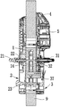
- FIG. 3 is an exploded perspective view showing the structure of an electronic lock portion of the embodiment of the present application.
- the present application discloses an electronic lock including a lock body 1, an outer lock body 3, an inner lock body 2, a finger vein collector 5 and a main control board 4.
- the lock body 1 is existing.
- the lock body which is commonly used in the technology, is mounted on the door panel 9.
- the outer lock body 3 and the inner lock body 2 are respectively disposed on opposite sides of the lock body 1, and the outer lock body 3 and the inner lock body 2 are mounted on the door panel 9.
- the outer lock body 3 includes a housing 30, an outer handle 31 rotatably mounted on the housing 30, a clutch device 32, and a driving device 34.
- the outer handle 31 passes through the clutch device 32.
- the drive shaft 14 is coupled and the drive unit 34 can act on the clutch unit 32 to engage the outer handle 31 with the drive shaft 14.
- the main control board 4 is located in the outer lock body 3 and can be connected to the housing 30 of the outer lock body 3.
- the finger vein collector 5 is mounted on the housing 30 of the outer lock body 3, and the finger vein collector 5 and the drive unit 34 are both The main control board 4 is electrically connected.
- the finger vein collector 5 includes a collection port 51 and an infrared circuit board 52.
- the infrared circuit board 52 is located in the outer lock body 3 and electrically connected to the main control board 4, and the infrared circuit board 52 is horizontally mounted in the housing 30.
- the collecting port 51 is embedded in the housing 30 of the outer locking body 3, the collecting port 51 is used for collecting the finger vein information of the user, and the infrared circuit board 52 sends the finger vein information collected by the collecting port 51 to the main control board 4, and the main control board 4
- the movement of the driving device 34 is controlled by the finger vein information collected by the finger vein collector 5, so that the clutch device 32 is engaged to engage the outer handle 31 with the drive shaft 14, that is, the main control plate 4 will receive the finger vein collected by the finger vein collector 5.
- the information is compared with the finger vein information of the user stored therein. When the two match, the movement of the driving device 34 can be controlled by the authentication to engage the outer handle 31 with the drive shaft 14 to realize the unlocking action.
- the clutch device 32 includes a connecting sleeve 321 and a driving sleeve 322 connected to the outer handle 31.
- the outer handle 31 and the driving sleeve 322 are preferably connected by a spline.
- One end of the 321 is connected to the transmission shaft 14.
- one end of the connecting sleeve 321 is provided with a square hole matching the shape of the transmission shaft 14.
- the connecting sleeve 321 is sleeved on the transmission shaft 14 and detachable from the transmission shaft 14 through the fastener.
- the other end of the connecting sleeve 321 is inserted into the driving sleeve 322 and a gap is reserved between the driving sleeve 322 and the driving sleeve 322.
- the driving sleeve 322 is provided with a movable guiding post 323, and the guiding post 323 passes through the reset member 324 and the driving sleeve. 322 is connected, and a socket 325 is formed on the connecting sleeve 321 corresponding to the guiding post 323 for inserting the guiding post 323.
- the driving device 34 can push the guiding post 323 into the insertion hole 325 to engage the connecting sleeve 321 with the driving sleeve 322, thereby The outer handle 31 is engaged with the drive shaft 14 to complete the unlocking.
- the clutch device 32 adopts the above form, and has a simple structure, convenient operation, and low cost on the basis of satisfying the use requirements.
- the clutch device 326 is provided with a stopper 326, and the stopper 326 is interlocked with the outer handle 31.
- the outer lock body 3 further includes a limiting device 33.
- the limiting device 33 is located in the housing 30 of the outer locking body 3, and the limiting device 33 is floatably disposed on the rotating path of the blocking block 326.
- the limiting device 33 enters the rotation path of the stopper 326 to limit the range of the rotation angle of the stopper 326. Since the stopper 326 is interlocked with the outer handle 31, the outer handle 31 is restricted. The range of rotation angles.
- the stopper device 33 moves out of the rotation path of the stopper 326 to release the restriction of the range of the rotation angle of the stopper 326, that is, the restriction of the range of the rotation angle of the outer handle 31 is released.
- the block 326 is preferably located on the drive sleeve 322 of the clutch device and integrally formed with the drive sleeve 322.
- the block 326 is provided with a through hole 327 communicating with the drive sleeve 322.
- the reset member 324 is a spring and a guide post.
- the 323 is located in the through hole 327 and is connected to the hole wall of the through hole 327 through the reset member 324.
- the guide post 323 protrudes toward the end of the stop away from the connecting sleeve 321 and does not contact the connecting sleeve 321 when subjected to
- the guide post 323 will move along the axis of the through hole 327 and partially insert into the insertion hole 325 of the connecting sleeve 321 to combine the driving sleeve 322 with the connecting sleeve 321 when the outer handle 31 is rotated.
- the driving sleeve 322 can be driven to rotate, and then the connecting sleeve 321 and the transmission shaft 14 are rotated to trigger the main locking tongue 11 of the locking body 1 to realize the opening and closing of the locking body 1.
- the limiting plate 331 When the limiting plate 331 is under pressure, it can be moved downward along the axial direction of the guiding rod 332 under the action of the pressure, that is, to move to the side close to the outer handle 31, and enter the rotation path of the stopper 326, limiting The range of the rotation angle of the stopper 326, which in turn defines the range of the rotation angle of the outer handle 31, when the pressure on the limiting plate 331 is released, the limiting plate 331 is directed upward along the axis of the guide rod 332 by the elastic force of the elastic member 333.
- the movement that is, the movement away from the side of the outer handle 31, removes the rotation path of the stopper 326 to release the limitation of the range of the rotation angle of the stopper 326, and then the range of the rotation angle of the outer handle 31 is released to meet the use requirements of different installation positions.
- the limiting device 33 adopts the above structure to facilitate installation and processing on the basis of satisfying the use requirements, and can fully utilize the axial space of the outer locking body 3, leaving installation space or working space for other mounting members, and maximally The size of the outer lock body 3 is reduced, and the cost is reduced.
- the driving device 34 preferably includes a pushing block 345 and a driving mechanism that drives the pushing block 345 to move toward or away from the guiding post 323.
- the pushing block 345 is preferably a curved plate structure and is connected to the power mechanism.
- the power mechanism drives the push block 345 to move toward the guide post 323, and the push block 345 contacts the guide post 323 and continues to advance, so that the guide post 323 passes along The axis of the hole 327 is moved to connect the connecting sleeve 321 with the driving sleeve 322 to engage the outer handle 31 with the transmission shaft 14.
- the outer handle 31 can be rotated to drive the main locking tongue 11 of the lock body 1 to complete the unlocking.
- the power mechanism drives the push block 345 to move away from the guide post 323, the guide post 323 is separated from the push block 345, and the guide post 323 is reset by the reset member 324.
- the connecting sleeve 321 is separated from the driving sleeve 322 to complete the locking.
- the power mechanism preferably includes a driving motor 342, a transmission mechanism 343 and an energy storage mechanism.
- the driving motor 342 is connected to the energy storage mechanism via a transmission mechanism 343, and the pushing block 345 is located on the energy storage mechanism.
- the driving motor 342, the transmission mechanism 343 and the energy storage mechanism are preferably Located in a casing 341, the driving motor 342 transmits power to the energy storage mechanism through the transmission mechanism 343.
- the energy storage mechanism stores energy to a critical point, it is triggered, and the push block 345 thereon is ejected to act on the clutch device 32.
- the unlocking action is completed, when the driving motor 342 rotates in the reverse direction, the energy storage mechanism is retracted to complete the closing operation.
- the gear 343a and the gear A transmission wheel is connected between the 343b, the transmission wheel is a double gear, the gear 343a and the gear 343b are both meshed with the transmission wheel, and the power of the driving motor 342 is transmitted to the rotating shaft 344 through the transmission mechanism 343, and the rotating shaft 344 is rotated, and the rotating shaft 344 is rotated.
- the offset 348 is rotated accordingly. Since the offset pin 348 is inserted into the spiral gap of the spring, when the offset pin 348 is rotated, since the two ends of the spring 346 are restricted by the slot 347 and cannot be rotated, the spring 346 can only be gradually compressed.
- the clutch device 32 is connected to the driving sleeve 322.
- the driving motor 342 is operated in the reverse direction, the spring 346 is released, so that the limiting block 349 and the pushing block 345 are reset, and the connecting sleeve 321 and the transmission are connected. 322 separation.
- the transmission mechanism 343 adopts an intermeshing gear structure, and the transmission wheel is designed as a double gear structure.
- the large gear of the double gear structure meshes with the gear 343a, and the pinion gear of the double gear structure meshes with the 343b, on the basis of transmitting power. It can also play the role of two-stage deceleration to meet the requirements of use.
- the transmission mechanism 343 is not limited to the above form.
- a worm gear can also be used.
- the worm wheel is coupled to the rotating shaft 344, and the worm is connected to the output shaft of the driving motor 342. .
- the outer lock body 3 is provided with a power emergency board 38 and a charging interface 39, and the power emergency board 38 is installed in the outer lock body 3.
- the charging interface 39 can be embedded in the housing 30 of the outer locking body 3.
- the power emergency board 38 is electrically connected to the charging interface 39 and the main control board 4.
- the charging interface 39 is preferably a USB interface, and the power emergency board 38 and the charging interface are provided. 39.
- the main control board 4 can be provided with an external charging power source in an emergency state. When the power of the electronic lock is exhausted, the charging can be performed through the charging interface 39 to prevent the electronic lock from being unusable due to the exhaustion of the power.
- the power emergency board 38 and the charging interface 39 are preferably located on the outer lock body 3, which can effectively prevent the electronic lock from being opened. It can be understood that the power emergency board 38 and the charging interface 39 are not limited to being located on the outer lock body 3. In some optional embodiments, the power emergency board 38 and the charging interface 39 can also be located on the inner lock body 2, It can also meet the charging requirements.
- a password collecting device 6 electrically connected to the main control board 4 is further disposed on the outer locking body 3, and the password collecting device 6 is embedded on the outer locking body 3 and includes a key display screen 61 and a password collecting device.
- 6 is configured to collect password information and transmit the password information to the main control board 4 to cause the main control board 4 to perform identity verification based on the password information.
- the specific main control board 4 can compare the collected password information with the password information of the user stored therein, and when the two match, the identity verification can be performed. At this time, the main control board 4 can send an unlock command to the drive unit 34 to complete the unlocking.
- the outer lock body 3 is further provided with a lock core 37 that cooperates with the lock body.
- the lock core 37 has a mechanical lock hole 371 for key unlocking, and the mechanical lock hole 371 is provided with an openable
- the keyhole cover 372, in particular, the keyhole cover 372 can be fastened to the housing 30 of the outer lock body 3. Therefore, the electronic lock provided by the present application can not only unlock the finger vein, but also unlock the password, and can also ensure the safety and practicability of the electronic lock by mechanical unlocking and triple unlocking.
- the external locking body 3 is provided with a motor switching interface 35 and a burglar alarm 36.
- the motor switching interface 35 is preferably embedded in the outer locking body 3, and the motor switching interface 35 and the burglar alarm 36 are both
- the main control board 4 is electrically connected.
- the burglar alarm 36 can issue a corresponding alarm prompt according to the illegal action event alarm command sent by the main control board 4 to warn the user that there is a risk of theft.
- the motor switching interface 35 is correspondingly provided.
- the lock body 1 can be provided with a motor and motor switching interface 35.
- the connection is further controlled by the main control board 4 to control the motor provided by the lock body 1 to complete the unlocking, so that the overall versatility of the electronic lock is higher, and it can be applied to different lock bodies 1.
- the outer lock body 3 is provided with a monitor 7 electrically connected to the main control board 4, the monitor 7 is embedded in the housing 30 of the outer lock body 3, and the monitor 7 is configured to monitor The external sound information and/or image information of the electronic lock is transmitted to the main control panel 4 to transmit sound information and/or image information.
- the monitor 7 can be used to capture the situation outside the user's door, so that the user can monitor the situation of the door of the house or the door of the company in real time.
- the outer locking body 3 is provided with a proximity sensing device 8 electrically connected to the main control board 4, and the proximity sensing device 8 is mounted on the housing 30 of the outer locking body 3, and the proximity sensing device 8 is It is configured to collect environmental information around the electronic lock and send environmental information to the main control board 4, and the main control board 4 can output a corresponding power supply mode according to the collected environmental information, such as a normal power supply mode or an energy-saving power supply mode, to achieve energy saving. purpose.
- a battery compartment 25 and a cover 26 fastened to the battery compartment 25 are disposed in the inner lock body 2, and the battery compartment 25 is provided with a main body.
- the control panel 4 is electrically connected to a battery pack for supplying power to the components of the electronic lock, such as powering the finger vein collector 5, the driving device 34, the password collecting device 6, and the like.
- the battery compartment 25 and the battery pack are not limited to being disposed in the inner lock body 2.
- the battery compartment 25 and the battery pack may be disposed in the outer lock body 3, correspondingly
- the cover 26 is also disposed in the outer lock body 3.
- the inner lock body 2 is provided with an anti-lock knob 23, and the anti-lock knob 23 is connected with the lock body 1 through the connecting shaft to control the opening and closing of the anti-lock tongue 12 of the lock body 1, by providing the anti-lock tongue 12 and The anti-lock knob 23 can be controlled to open and close the anti-lock tongue 12, so that the user can unlock the electronic lock indoors, and the outdoor can not be opened, thereby improving the overall safety performance of the electronic lock.
- a function setting device 24 electrically connected to the main control board 4 is further disposed in the inner lock body 2.
- the function setting device 24 includes a display screen 241 and a function key board 242, and a function key board.
- a connecting post is preferably provided on the 242.
- the function key plate 242 is located in the housing 20 of the inner locking body 2 and is connected to the housing 20 of the inner locking body 2 via a connecting post.
- the function setting device 24 is located above the battery compartment 25 and is enclosed by the cover 26 in the housing 20 of the inner lock body 2, and the function setting device 24 is configured to input the user's finger vein information and password information, and to the main control
- the board 4 sends the user's finger vein information and password information, and the vein information and the password information are stored in the main control board 4 for use with the finger vein information collected by the finger vein collector 5 and the password information collected by the password collection device 6. Comparison.
- the electronic lock provided by the embodiment of the present application can use the finger vein information to unlock, can not be imitated, can improve the safety performance of the electronic lock, and only needs to be equipped with a set of locks to meet different use requirements, reducing production and stocking costs. Easy to promote.
Abstract
L'invention concerne un verrou électronique, comprenant un corps de verrou (1), un corps de verrou externe (3), un corps de verrou interne (2), un panneau de commande principal (4) et un collecteur de veine de doigt (5). Le corps de verrou (1) comprend une languette de verrouillage principale (11) et un trou d'insertion (13), un arbre de transmission rotatif (14) étant inséré dans le trou d'insertion (13). Le corps de verrou extérieur (3) comprend une poignée extérieure rotative (31), un dispositif d'embrayage (32), un dispositif de limitation de position (33) et un dispositif d'entraînement (34), la poignée extérieure (31) étant reliée à l'arbre de transmission (14) par l'intermédiaire du dispositif d'embrayage (32) ; un obturateur (326) est disposé sur le dispositif d'embrayage (32) ; l'obturateur (326) est relié à la poignée extérieure (31) ; et le dispositif de limitation de position (33) est disposé sur un trajet de rotation de l'obturateur (326) de manière flottante.
Applications Claiming Priority (2)
| Application Number | Priority Date | Filing Date | Title |
|---|---|---|---|
| CN201720825687.1 | 2017-07-07 | ||
| CN201720825687.1U CN207131202U (zh) | 2017-07-07 | 2017-07-07 | 电子锁 |
Publications (1)
| Publication Number | Publication Date |
|---|---|
| WO2019007392A1 true WO2019007392A1 (fr) | 2019-01-10 |
Family
ID=61633481
Family Applications (1)
| Application Number | Title | Priority Date | Filing Date |
|---|---|---|---|
| PCT/CN2018/094642 WO2019007392A1 (fr) | 2017-07-07 | 2018-07-05 | Verrou électronique |
Country Status (2)
| Country | Link |
|---|---|
| CN (1) | CN207131202U (fr) |
| WO (1) | WO2019007392A1 (fr) |
Families Citing this family (4)
| Publication number | Priority date | Publication date | Assignee | Title |
|---|---|---|---|---|
| CN207131202U (zh) * | 2017-07-07 | 2018-03-23 | 燕南国创科技(北京)有限公司 | 电子锁 |
| CN109488119A (zh) * | 2018-10-12 | 2019-03-19 | 深圳市律远汇智科技有限公司 | 一种基于区块链技术的续航能力强的智能门锁 |
| CN111140095A (zh) * | 2020-01-13 | 2020-05-12 | 深圳市高盾电子有限公司 | 锁具和门体 |
| TWI800125B (zh) * | 2021-11-29 | 2023-04-21 | 百富股份有限公司 | 無線控制電子大門鎖 |
Citations (8)
| Publication number | Priority date | Publication date | Assignee | Title |
|---|---|---|---|---|
| WO1997028334A1 (fr) * | 1996-01-31 | 1997-08-07 | Sargent Manufacturing Company | Serrure a mortaise reversible |
| US6145353A (en) * | 1999-02-02 | 2000-11-14 | Unican Electronics | Electronically activated door lock assembly |
| US20040123427A1 (en) * | 2002-12-30 | 2004-07-01 | Taiwan Fu Hsing Industrial Co., Ltd. | Adjustable handle assembly for a lock |
| CN205153707U (zh) * | 2015-11-19 | 2016-04-13 | 北京安恒利通科技股份公司 | 电子门锁离合装置 |
| CN105971410A (zh) * | 2016-07-11 | 2016-09-28 | 南京东屋电气有限公司 | 电子锁 |
| CN205777993U (zh) * | 2016-05-12 | 2016-12-07 | 江门市科裕智能科技有限公司 | 一种执手可自由换向的电子门锁 |
| CN106760944A (zh) * | 2016-12-30 | 2017-05-31 | 徐高强 | 可转换方向的门把手 |
| CN207131202U (zh) * | 2017-07-07 | 2018-03-23 | 燕南国创科技(北京)有限公司 | 电子锁 |
-
2017
- 2017-07-07 CN CN201720825687.1U patent/CN207131202U/zh not_active Expired - Fee Related
-
2018
- 2018-07-05 WO PCT/CN2018/094642 patent/WO2019007392A1/fr active Application Filing
Patent Citations (8)
| Publication number | Priority date | Publication date | Assignee | Title |
|---|---|---|---|---|
| WO1997028334A1 (fr) * | 1996-01-31 | 1997-08-07 | Sargent Manufacturing Company | Serrure a mortaise reversible |
| US6145353A (en) * | 1999-02-02 | 2000-11-14 | Unican Electronics | Electronically activated door lock assembly |
| US20040123427A1 (en) * | 2002-12-30 | 2004-07-01 | Taiwan Fu Hsing Industrial Co., Ltd. | Adjustable handle assembly for a lock |
| CN205153707U (zh) * | 2015-11-19 | 2016-04-13 | 北京安恒利通科技股份公司 | 电子门锁离合装置 |
| CN205777993U (zh) * | 2016-05-12 | 2016-12-07 | 江门市科裕智能科技有限公司 | 一种执手可自由换向的电子门锁 |
| CN105971410A (zh) * | 2016-07-11 | 2016-09-28 | 南京东屋电气有限公司 | 电子锁 |
| CN106760944A (zh) * | 2016-12-30 | 2017-05-31 | 徐高强 | 可转换方向的门把手 |
| CN207131202U (zh) * | 2017-07-07 | 2018-03-23 | 燕南国创科技(北京)有限公司 | 电子锁 |
Also Published As
| Publication number | Publication date |
|---|---|
| CN207131202U (zh) | 2018-03-23 |
Similar Documents
| Publication | Publication Date | Title |
|---|---|---|
| WO2019007392A1 (fr) | Verrou électronique | |
| CN104034203B (zh) | 枪支智能安全锁 | |
| CN205743348U (zh) | 机柜电子锁 | |
| CN202299736U (zh) | 一种安全防盗锁 | |
| CN107355141A (zh) | 一种将传统机械锁改造为智能电子锁的装置 | |
| CN105333768B (zh) | 枪支扳机锁 | |
| WO2021189737A1 (fr) | Verrou et système de porte | |
| CN206309149U (zh) | 安全空转电子锁 | |
| CN113153011A (zh) | 智能门锁 | |
| CN200989097Y (zh) | 门锁遥控防盗装置 | |
| CN207110691U (zh) | 一种后置离合游离把手电子锁 | |
| CN104034202B (zh) | 一种枪支智能安全锁 | |
| CN201627476U (zh) | 一种遥控电子保险柜 | |
| CN202544555U (zh) | 机械式无电源电子防盗锁 | |
| CN108798297A (zh) | 一种保险柜锁具 | |
| CN107975298A (zh) | 一种指纹密码锁 | |
| CN102086718B (zh) | 一种带电磁离合器的电子锁眼保护装置 | |
| CN203928868U (zh) | 一种枪支智能安全锁 | |
| CN208546052U (zh) | 一种保险柜锁具 | |
| CN209760995U (zh) | 一种电动离合门把手 | |
| CN207131209U (zh) | 一种将传统机械锁改造为智能电子锁的装置 | |
| CN209837977U (zh) | 一种智能抽屉锁 | |
| CN108505852A (zh) | 一种电控防盗车门锁 | |
| CN110984710A (zh) | 一种面部识别智能锁 | |
| CN110847712A (zh) | 一种智能门锁 |
Legal Events
| Date | Code | Title | Description |
|---|---|---|---|
| 121 | Ep: the epo has been informed by wipo that ep was designated in this application |
Ref document number: 18828696 Country of ref document: EP Kind code of ref document: A1 |
|
| NENP | Non-entry into the national phase |
Ref country code: DE |
|
| 32PN | Ep: public notification in the ep bulletin as address of the adressee cannot be established |
Free format text: NOTING OF LOSS OF RIGHTS PURSUANT TO RULE 112(1) EPC (EPO FORM 1205A DATED 25/07/2020 |
|
| 122 | Ep: pct application non-entry in european phase |
Ref document number: 18828696 Country of ref document: EP Kind code of ref document: A1 |