WO2019007392A1 - Electronic lock - Google Patents
Electronic lock Download PDFInfo
- Publication number
- WO2019007392A1 WO2019007392A1 PCT/CN2018/094642 CN2018094642W WO2019007392A1 WO 2019007392 A1 WO2019007392 A1 WO 2019007392A1 CN 2018094642 W CN2018094642 W CN 2018094642W WO 2019007392 A1 WO2019007392 A1 WO 2019007392A1
- Authority
- WO
- WIPO (PCT)
- Prior art keywords
- lock body
- lock
- main control
- control board
- electronic lock
- Prior art date
Links
Images


Classifications
-
- E—FIXED CONSTRUCTIONS
- E05—LOCKS; KEYS; WINDOW OR DOOR FITTINGS; SAFES
- E05B—LOCKS; ACCESSORIES THEREFOR; HANDCUFFS
- E05B15/00—Other details of locks; Parts for engagement by bolts of fastening devices
-
- E—FIXED CONSTRUCTIONS
- E05—LOCKS; KEYS; WINDOW OR DOOR FITTINGS; SAFES
- E05B—LOCKS; ACCESSORIES THEREFOR; HANDCUFFS
- E05B3/00—Fastening knobs or handles to lock or latch parts
-
- E—FIXED CONSTRUCTIONS
- E05—LOCKS; KEYS; WINDOW OR DOOR FITTINGS; SAFES
- E05B—LOCKS; ACCESSORIES THEREFOR; HANDCUFFS
- E05B45/00—Alarm locks
- E05B45/06—Electric alarm locks
-
- E—FIXED CONSTRUCTIONS
- E05—LOCKS; KEYS; WINDOW OR DOOR FITTINGS; SAFES
- E05B—LOCKS; ACCESSORIES THEREFOR; HANDCUFFS
- E05B47/00—Operating or controlling locks or other fastening devices by electric or magnetic means
-
- E—FIXED CONSTRUCTIONS
- E05—LOCKS; KEYS; WINDOW OR DOOR FITTINGS; SAFES
- E05B—LOCKS; ACCESSORIES THEREFOR; HANDCUFFS
- E05B49/00—Electric permutation locks; Circuits therefor ; Mechanical aspects of electronic locks; Mechanical keys therefor
-
- G—PHYSICS
- G07—CHECKING-DEVICES
- G07C—TIME OR ATTENDANCE REGISTERS; REGISTERING OR INDICATING THE WORKING OF MACHINES; GENERATING RANDOM NUMBERS; VOTING OR LOTTERY APPARATUS; ARRANGEMENTS, SYSTEMS OR APPARATUS FOR CHECKING NOT PROVIDED FOR ELSEWHERE
- G07C9/00—Individual registration on entry or exit
Definitions
- An electronic lock includes a lock body, an inner lock body, an outer lock body, a finger vein collector, and a main control board.
- the main control board controls the movement of the drive device by the finger vein information collected by the finger vein collector.
- the driving device acts on the clutch device to engage or disengage the outer handle with the drive shaft, and uses the finger vein information to unlock. Since the finger vein information has a living body performance, it cannot be imitated, and the safety performance of the electronic lock can be improved.
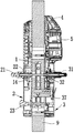
- FIG. 3 is an exploded perspective view showing the structure of an electronic lock portion of the embodiment of the present application.
- the present application discloses an electronic lock including a lock body 1, an outer lock body 3, an inner lock body 2, a finger vein collector 5 and a main control board 4.
- the lock body 1 is existing.
- the lock body which is commonly used in the technology, is mounted on the door panel 9.
- the outer lock body 3 and the inner lock body 2 are respectively disposed on opposite sides of the lock body 1, and the outer lock body 3 and the inner lock body 2 are mounted on the door panel 9.
- the outer lock body 3 includes a housing 30, an outer handle 31 rotatably mounted on the housing 30, a clutch device 32, and a driving device 34.
- the outer handle 31 passes through the clutch device 32.
- the drive shaft 14 is coupled and the drive unit 34 can act on the clutch unit 32 to engage the outer handle 31 with the drive shaft 14.
- the main control board 4 is located in the outer lock body 3 and can be connected to the housing 30 of the outer lock body 3.
- the finger vein collector 5 is mounted on the housing 30 of the outer lock body 3, and the finger vein collector 5 and the drive unit 34 are both The main control board 4 is electrically connected.
- the finger vein collector 5 includes a collection port 51 and an infrared circuit board 52.
- the infrared circuit board 52 is located in the outer lock body 3 and electrically connected to the main control board 4, and the infrared circuit board 52 is horizontally mounted in the housing 30.
- the collecting port 51 is embedded in the housing 30 of the outer locking body 3, the collecting port 51 is used for collecting the finger vein information of the user, and the infrared circuit board 52 sends the finger vein information collected by the collecting port 51 to the main control board 4, and the main control board 4
- the movement of the driving device 34 is controlled by the finger vein information collected by the finger vein collector 5, so that the clutch device 32 is engaged to engage the outer handle 31 with the drive shaft 14, that is, the main control plate 4 will receive the finger vein collected by the finger vein collector 5.
- the information is compared with the finger vein information of the user stored therein. When the two match, the movement of the driving device 34 can be controlled by the authentication to engage the outer handle 31 with the drive shaft 14 to realize the unlocking action.
- the clutch device 32 includes a connecting sleeve 321 and a driving sleeve 322 connected to the outer handle 31.
- the outer handle 31 and the driving sleeve 322 are preferably connected by a spline.
- One end of the 321 is connected to the transmission shaft 14.
- one end of the connecting sleeve 321 is provided with a square hole matching the shape of the transmission shaft 14.
- the connecting sleeve 321 is sleeved on the transmission shaft 14 and detachable from the transmission shaft 14 through the fastener.
- the other end of the connecting sleeve 321 is inserted into the driving sleeve 322 and a gap is reserved between the driving sleeve 322 and the driving sleeve 322.
- the driving sleeve 322 is provided with a movable guiding post 323, and the guiding post 323 passes through the reset member 324 and the driving sleeve. 322 is connected, and a socket 325 is formed on the connecting sleeve 321 corresponding to the guiding post 323 for inserting the guiding post 323.
- the driving device 34 can push the guiding post 323 into the insertion hole 325 to engage the connecting sleeve 321 with the driving sleeve 322, thereby The outer handle 31 is engaged with the drive shaft 14 to complete the unlocking.
- the clutch device 32 adopts the above form, and has a simple structure, convenient operation, and low cost on the basis of satisfying the use requirements.
- the clutch device 326 is provided with a stopper 326, and the stopper 326 is interlocked with the outer handle 31.
- the outer lock body 3 further includes a limiting device 33.
- the limiting device 33 is located in the housing 30 of the outer locking body 3, and the limiting device 33 is floatably disposed on the rotating path of the blocking block 326.
- the limiting device 33 enters the rotation path of the stopper 326 to limit the range of the rotation angle of the stopper 326. Since the stopper 326 is interlocked with the outer handle 31, the outer handle 31 is restricted. The range of rotation angles.
- the stopper device 33 moves out of the rotation path of the stopper 326 to release the restriction of the range of the rotation angle of the stopper 326, that is, the restriction of the range of the rotation angle of the outer handle 31 is released.
- the block 326 is preferably located on the drive sleeve 322 of the clutch device and integrally formed with the drive sleeve 322.
- the block 326 is provided with a through hole 327 communicating with the drive sleeve 322.
- the reset member 324 is a spring and a guide post.
- the 323 is located in the through hole 327 and is connected to the hole wall of the through hole 327 through the reset member 324.
- the guide post 323 protrudes toward the end of the stop away from the connecting sleeve 321 and does not contact the connecting sleeve 321 when subjected to
- the guide post 323 will move along the axis of the through hole 327 and partially insert into the insertion hole 325 of the connecting sleeve 321 to combine the driving sleeve 322 with the connecting sleeve 321 when the outer handle 31 is rotated.
- the driving sleeve 322 can be driven to rotate, and then the connecting sleeve 321 and the transmission shaft 14 are rotated to trigger the main locking tongue 11 of the locking body 1 to realize the opening and closing of the locking body 1.
- the limiting plate 331 When the limiting plate 331 is under pressure, it can be moved downward along the axial direction of the guiding rod 332 under the action of the pressure, that is, to move to the side close to the outer handle 31, and enter the rotation path of the stopper 326, limiting The range of the rotation angle of the stopper 326, which in turn defines the range of the rotation angle of the outer handle 31, when the pressure on the limiting plate 331 is released, the limiting plate 331 is directed upward along the axis of the guide rod 332 by the elastic force of the elastic member 333.
- the movement that is, the movement away from the side of the outer handle 31, removes the rotation path of the stopper 326 to release the limitation of the range of the rotation angle of the stopper 326, and then the range of the rotation angle of the outer handle 31 is released to meet the use requirements of different installation positions.
- the limiting device 33 adopts the above structure to facilitate installation and processing on the basis of satisfying the use requirements, and can fully utilize the axial space of the outer locking body 3, leaving installation space or working space for other mounting members, and maximally The size of the outer lock body 3 is reduced, and the cost is reduced.
- the driving device 34 preferably includes a pushing block 345 and a driving mechanism that drives the pushing block 345 to move toward or away from the guiding post 323.
- the pushing block 345 is preferably a curved plate structure and is connected to the power mechanism.
- the power mechanism drives the push block 345 to move toward the guide post 323, and the push block 345 contacts the guide post 323 and continues to advance, so that the guide post 323 passes along The axis of the hole 327 is moved to connect the connecting sleeve 321 with the driving sleeve 322 to engage the outer handle 31 with the transmission shaft 14.
- the outer handle 31 can be rotated to drive the main locking tongue 11 of the lock body 1 to complete the unlocking.
- the power mechanism drives the push block 345 to move away from the guide post 323, the guide post 323 is separated from the push block 345, and the guide post 323 is reset by the reset member 324.
- the connecting sleeve 321 is separated from the driving sleeve 322 to complete the locking.
- the power mechanism preferably includes a driving motor 342, a transmission mechanism 343 and an energy storage mechanism.
- the driving motor 342 is connected to the energy storage mechanism via a transmission mechanism 343, and the pushing block 345 is located on the energy storage mechanism.
- the driving motor 342, the transmission mechanism 343 and the energy storage mechanism are preferably Located in a casing 341, the driving motor 342 transmits power to the energy storage mechanism through the transmission mechanism 343.
- the energy storage mechanism stores energy to a critical point, it is triggered, and the push block 345 thereon is ejected to act on the clutch device 32.
- the unlocking action is completed, when the driving motor 342 rotates in the reverse direction, the energy storage mechanism is retracted to complete the closing operation.
- the gear 343a and the gear A transmission wheel is connected between the 343b, the transmission wheel is a double gear, the gear 343a and the gear 343b are both meshed with the transmission wheel, and the power of the driving motor 342 is transmitted to the rotating shaft 344 through the transmission mechanism 343, and the rotating shaft 344 is rotated, and the rotating shaft 344 is rotated.
- the offset 348 is rotated accordingly. Since the offset pin 348 is inserted into the spiral gap of the spring, when the offset pin 348 is rotated, since the two ends of the spring 346 are restricted by the slot 347 and cannot be rotated, the spring 346 can only be gradually compressed.
- the clutch device 32 is connected to the driving sleeve 322.
- the driving motor 342 is operated in the reverse direction, the spring 346 is released, so that the limiting block 349 and the pushing block 345 are reset, and the connecting sleeve 321 and the transmission are connected. 322 separation.
- the transmission mechanism 343 adopts an intermeshing gear structure, and the transmission wheel is designed as a double gear structure.
- the large gear of the double gear structure meshes with the gear 343a, and the pinion gear of the double gear structure meshes with the 343b, on the basis of transmitting power. It can also play the role of two-stage deceleration to meet the requirements of use.
- the transmission mechanism 343 is not limited to the above form.
- a worm gear can also be used.
- the worm wheel is coupled to the rotating shaft 344, and the worm is connected to the output shaft of the driving motor 342. .
- the outer lock body 3 is provided with a power emergency board 38 and a charging interface 39, and the power emergency board 38 is installed in the outer lock body 3.
- the charging interface 39 can be embedded in the housing 30 of the outer locking body 3.
- the power emergency board 38 is electrically connected to the charging interface 39 and the main control board 4.
- the charging interface 39 is preferably a USB interface, and the power emergency board 38 and the charging interface are provided. 39.
- the main control board 4 can be provided with an external charging power source in an emergency state. When the power of the electronic lock is exhausted, the charging can be performed through the charging interface 39 to prevent the electronic lock from being unusable due to the exhaustion of the power.
- the power emergency board 38 and the charging interface 39 are preferably located on the outer lock body 3, which can effectively prevent the electronic lock from being opened. It can be understood that the power emergency board 38 and the charging interface 39 are not limited to being located on the outer lock body 3. In some optional embodiments, the power emergency board 38 and the charging interface 39 can also be located on the inner lock body 2, It can also meet the charging requirements.
- a password collecting device 6 electrically connected to the main control board 4 is further disposed on the outer locking body 3, and the password collecting device 6 is embedded on the outer locking body 3 and includes a key display screen 61 and a password collecting device.
- 6 is configured to collect password information and transmit the password information to the main control board 4 to cause the main control board 4 to perform identity verification based on the password information.
- the specific main control board 4 can compare the collected password information with the password information of the user stored therein, and when the two match, the identity verification can be performed. At this time, the main control board 4 can send an unlock command to the drive unit 34 to complete the unlocking.
- the outer lock body 3 is further provided with a lock core 37 that cooperates with the lock body.
- the lock core 37 has a mechanical lock hole 371 for key unlocking, and the mechanical lock hole 371 is provided with an openable
- the keyhole cover 372, in particular, the keyhole cover 372 can be fastened to the housing 30 of the outer lock body 3. Therefore, the electronic lock provided by the present application can not only unlock the finger vein, but also unlock the password, and can also ensure the safety and practicability of the electronic lock by mechanical unlocking and triple unlocking.
- the external locking body 3 is provided with a motor switching interface 35 and a burglar alarm 36.
- the motor switching interface 35 is preferably embedded in the outer locking body 3, and the motor switching interface 35 and the burglar alarm 36 are both
- the main control board 4 is electrically connected.
- the burglar alarm 36 can issue a corresponding alarm prompt according to the illegal action event alarm command sent by the main control board 4 to warn the user that there is a risk of theft.
- the motor switching interface 35 is correspondingly provided.
- the lock body 1 can be provided with a motor and motor switching interface 35.
- the connection is further controlled by the main control board 4 to control the motor provided by the lock body 1 to complete the unlocking, so that the overall versatility of the electronic lock is higher, and it can be applied to different lock bodies 1.
- the outer lock body 3 is provided with a monitor 7 electrically connected to the main control board 4, the monitor 7 is embedded in the housing 30 of the outer lock body 3, and the monitor 7 is configured to monitor The external sound information and/or image information of the electronic lock is transmitted to the main control panel 4 to transmit sound information and/or image information.
- the monitor 7 can be used to capture the situation outside the user's door, so that the user can monitor the situation of the door of the house or the door of the company in real time.
- the outer locking body 3 is provided with a proximity sensing device 8 electrically connected to the main control board 4, and the proximity sensing device 8 is mounted on the housing 30 of the outer locking body 3, and the proximity sensing device 8 is It is configured to collect environmental information around the electronic lock and send environmental information to the main control board 4, and the main control board 4 can output a corresponding power supply mode according to the collected environmental information, such as a normal power supply mode or an energy-saving power supply mode, to achieve energy saving. purpose.
- a battery compartment 25 and a cover 26 fastened to the battery compartment 25 are disposed in the inner lock body 2, and the battery compartment 25 is provided with a main body.
- the control panel 4 is electrically connected to a battery pack for supplying power to the components of the electronic lock, such as powering the finger vein collector 5, the driving device 34, the password collecting device 6, and the like.
- the battery compartment 25 and the battery pack are not limited to being disposed in the inner lock body 2.
- the battery compartment 25 and the battery pack may be disposed in the outer lock body 3, correspondingly
- the cover 26 is also disposed in the outer lock body 3.
- the inner lock body 2 is provided with an anti-lock knob 23, and the anti-lock knob 23 is connected with the lock body 1 through the connecting shaft to control the opening and closing of the anti-lock tongue 12 of the lock body 1, by providing the anti-lock tongue 12 and The anti-lock knob 23 can be controlled to open and close the anti-lock tongue 12, so that the user can unlock the electronic lock indoors, and the outdoor can not be opened, thereby improving the overall safety performance of the electronic lock.
- a function setting device 24 electrically connected to the main control board 4 is further disposed in the inner lock body 2.
- the function setting device 24 includes a display screen 241 and a function key board 242, and a function key board.
- a connecting post is preferably provided on the 242.
- the function key plate 242 is located in the housing 20 of the inner locking body 2 and is connected to the housing 20 of the inner locking body 2 via a connecting post.
- the function setting device 24 is located above the battery compartment 25 and is enclosed by the cover 26 in the housing 20 of the inner lock body 2, and the function setting device 24 is configured to input the user's finger vein information and password information, and to the main control
- the board 4 sends the user's finger vein information and password information, and the vein information and the password information are stored in the main control board 4 for use with the finger vein information collected by the finger vein collector 5 and the password information collected by the password collection device 6. Comparison.
- the electronic lock provided by the embodiment of the present application can use the finger vein information to unlock, can not be imitated, can improve the safety performance of the electronic lock, and only needs to be equipped with a set of locks to meet different use requirements, reducing production and stocking costs. Easy to promote.
Landscapes
- Engineering & Computer Science (AREA)
- Mechanical Engineering (AREA)
- Physics & Mathematics (AREA)
- General Physics & Mathematics (AREA)
- Lock And Its Accessories (AREA)
Abstract
Disclosed is an electronic lock, comprising a lock body (1), an outer lock body (3), an inner lock body (2), a main control panel (4) and a finger vein collector (5). The lock body (1) comprises a main lock tongue (11) and an insertion hole (13), wherein a rotatable transmission shaft (14) is inserted into the insertion hole (13). The outer lock body (3) comprises a rotatable outer handle (31), a clutch device (32), a position-limiting device (33) and a driving device (34), wherein the outer handle (31) is connected to the transmission shaft (14) via the clutch device (32); a stopper (326) is arranged on the clutch device (32); the stopper (326) is linked with the outer handle (31); and the position-limiting device (33) is arranged on a rotation path of the stopper (326) in a floatable manner.
Description
相关申请的交叉引用Cross-reference to related applications
本申请要求享有于2017年7月7日提交的名称为“电子锁”的中国专利申请201720825687.1的优先权,该申请的全部内容通过引用并入本文中。This application claims the benefit of priority to the benefit of the benefit of the benefit of the benefit of the benefit of the benefit of the benefit of the benefit of the benefit of the benefit of the benefit of the benefit of the benefit of the benefit of the benefit of the benefit of the benefit of the benefit of the benefit of the benefit of the disclosure.
本申请涉及锁具技术领域,特别是涉及一种电子锁。The present application relates to the field of lock technology, and in particular to an electronic lock.
目前,随着社会的进步和人们的需求,电子锁在安全技术防范领域的使用率越来越高。电子锁区别于传统的机械锁,其是使用非机械钥匙如随机码、二维码、指纹识别等作为用户识别ID而实现锁的开闭,相对于传统的机械锁具有结构简单,安全级别高等优点,因此得到了广泛的应用。At present, with the progress of society and the needs of people, the use rate of electronic locks in the field of security technology prevention is getting higher and higher. The electronic lock is different from the traditional mechanical lock, which uses a non-mechanical key such as random code, two-dimensional code, fingerprint recognition, etc. as the user identification ID to realize the opening and closing of the lock, and has a simple structure and a high security level compared with the conventional mechanical lock. The advantages are therefore widely used.
然而,现有的电子锁,如指纹锁、二维码等,具有可模仿性,容易被伪造,安全性能低,极大的限制了电子锁的推广使用。同时,由于用户的门的使用方式不同,即有左开门及右开门之分,使得电子锁把手的布置方向不同,则需要厂家根据门的使用方式同时配备两种类型的锁,增加了生产备货成本。However, existing electronic locks, such as fingerprint locks, two-dimensional codes, etc., are imitative, easily forged, and have low security performance, which greatly limits the promotion and use of electronic locks. At the same time, because the user's door is used in different ways, that is, there are left and right door openings, so that the arrangement direction of the electronic lock handle is different, the manufacturer needs to be equipped with two types of locks according to the way of using the door, thereby increasing production and stocking. cost.
实用新型内容Utility model content
本申请实施例提供一种电子锁,利用指静脉信息进行开锁,不可模仿,能够提高电子锁的安全性能,同时只需配备一套锁即可满足不同的使用需求,降低生产备货成本,提高了售前沟通效率。The embodiment of the present application provides an electronic lock, which uses the finger vein information to unlock, can not be imitated, can improve the safety performance of the electronic lock, and only needs to be equipped with a set of locks to meet different use requirements, reduce production and stocking costs, and improve Pre-sales communication efficiency.
一方面,根据本申请实施例提出了一种电子锁,包括锁体,包括主锁舌及插孔,插孔内插接有可转动的传动轴,以控制主锁舌的开合;外锁身,包括可转动的外把手、离合装置、限位装置及驱动装置,外把手通过 离合装置与传动轴连接,驱动装置能够作用于离合装置以使外把手与传动轴接合,离合装置上设置有挡块,挡块与外把手联动,限位装置可浮动的设置在挡块的旋转路径上;当限位装置受到压力时,限位装置进入挡块的旋转路径中以限制挡块的旋转角度范围,当解除作用于限位装置的压力时,限位装置移出挡块的旋转路径,以解除对挡块旋转角度范围的限制;内锁身,包括可转动的内把手,内把手与传动轴连接;主控制板,位于内锁身或外锁身内;指静脉采集器,位于外锁身上;其中,外锁身及内锁身分别位于锁体的两侧且相对设置,指静脉采集器及驱动装置均与主控制板电气连接,主控制板通过指静脉采集器采集的指静脉信息控制驱动装置运动以使外把手与传动轴接合。In one aspect, an electronic lock is provided according to an embodiment of the present application, including a lock body, including a main lock tongue and a jack, and a rotatable drive shaft is inserted into the jack to control opening and closing of the main lock tongue; The body comprises a rotatable outer handle, a clutch device, a limiting device and a driving device, and the outer handle is connected to the transmission shaft through the clutch device, and the driving device can act on the clutch device to engage the outer handle with the transmission shaft, and the clutch device is provided with The stopper and the stopper are interlocked with the outer handle, and the limiting device is floatingly disposed on the rotating path of the stopper; when the limiting device is under pressure, the limiting device enters the rotating path of the blocking to limit the rotation angle of the blocking member; Range, when the pressure acting on the limiting device is released, the limiting device moves out of the rotating path of the stopper to release the limitation of the range of the rotation angle of the stopper; the inner locking body includes a rotatable inner handle, the inner handle and the transmission shaft The main control board is located in the inner lock body or the outer lock body; the finger vein collector is located on the outer lock body; wherein the outer lock body and the inner lock body are respectively located on opposite sides of the lock body and are oppositely arranged, The pulse collector and the driving device are electrically connected to the main control board, and the main control board controls the movement of the driving device through the finger vein information collected by the finger vein collector to engage the outer handle with the transmission shaft.
根据本申请实施例提供的电子锁,其包括锁体、内锁身、外锁身、指静脉采集器及主控制板,主控制板通过指静脉采集器采集的指静脉信息控制驱动装置的运动,使得驱动装置作用于离合装置,以使外把手与传动轴接合或分离,利用指静脉信息进行开锁,由于指静脉信息具有活体性能,不可模仿,能够提高电子锁的安全性能。An electronic lock according to an embodiment of the present application includes a lock body, an inner lock body, an outer lock body, a finger vein collector, and a main control board. The main control board controls the movement of the drive device by the finger vein information collected by the finger vein collector. The driving device acts on the clutch device to engage or disengage the outer handle with the drive shaft, and uses the finger vein information to unlock. Since the finger vein information has a living body performance, it cannot be imitated, and the safety performance of the electronic lock can be improved.
进一步的,在离合装置上设置有能够与外把手联动的挡块,同时在挡块的旋转路径上设置有可浮动的限位装置,使其在受压时,能够限制挡块的旋转角度范围,在解除压力时,相应解除挡块旋转角度范围的限制,即,能够限制外把手的旋转角度范围或解除外把手的旋转角度范围的限制。解除限位装置所受压力时,可以根据电子锁的安装位置不同,调整把手的布置方向,以满足使用要求,厂家只需配备一套锁即可满足不同的使用需求,降低生产备货成本。Further, the clutch device is provided with a stopper capable of interlocking with the outer handle, and at the same time, a floatable limiting device is disposed on the rotating path of the stopper, so that when the pressure is pressed, the range of the rotation angle of the stopper can be restricted. When the pressure is released, the limit of the range of the rotation angle of the stopper is correspondingly released, that is, the range of the rotation angle of the outer handle or the limitation of the range of the rotation angle of the outer handle can be restricted. When the pressure of the limiting device is released, the arrangement direction of the handle can be adjusted according to the installation position of the electronic lock to meet the requirements of use. The manufacturer only needs to be equipped with a set of locks to meet different usage requirements and reduce the production and storage cost.
下面将参考附图来描述本申请示例性实施例的特征、优点和技术效果。Features, advantages, and technical effects of the exemplary embodiments of the present application will be described below with reference to the accompanying drawings.
图1是本申请实施例的电子锁安装在门板上的整体结构示意图;1 is a schematic view showing the overall structure of an electronic lock mounted on a door panel according to an embodiment of the present application;
图2是本申请实施例的电子锁安装在门板上的剖面结构示意图;2 is a cross-sectional structural view showing an electronic lock mounted on a door panel according to an embodiment of the present application;
图3是本申请实施例的电子锁部分结构的分解示意图;3 is an exploded perspective view showing the structure of an electronic lock portion of the embodiment of the present application;
图4是本申请实施例的锁体的结构示意图;4 is a schematic structural view of a lock body according to an embodiment of the present application;
图5是本申请实施例的内锁身的结构示意图;FIG. 5 is a schematic structural view of an inner lock body according to an embodiment of the present application; FIG.
图6是本申请实施例的内锁身的剖面结构示意图;6 is a schematic cross-sectional structural view of an inner lock body according to an embodiment of the present application;
图7是本申请实施例的外锁身的结构示意图;7 is a schematic structural view of an outer lock body according to an embodiment of the present application;
图8是本申请实施例的外锁身的剖面结构示意图;8 is a schematic cross-sectional structural view of an outer lock body according to an embodiment of the present application;
图9是本申请实施例的外把手、内把手与传动轴连接的分解示意图;Figure 9 is an exploded perspective view showing the connection of the outer handle and the inner handle to the drive shaft in the embodiment of the present application;
图10是本申请实施例的外把手、内把手与传动轴连接的剖面结构示意图;Figure 10 is a cross-sectional structural view showing the connection of the outer handle and the inner handle to the drive shaft in the embodiment of the present application;
图11是本申请实施例的离合装置的剖面结构示意图;11 is a schematic cross-sectional structural view of a clutch device according to an embodiment of the present application;
图12是本申请实施例的外锁身的内部结构示意图;12 is a schematic view showing the internal structure of an outer lock body according to an embodiment of the present application;
图13是本申请实施例的驱动装置的剖面结构示意图;13 is a schematic cross-sectional structural view of a driving device according to an embodiment of the present application;
图14是本申请实施例的驱动装置的工作原理图;Figure 14 is a schematic view showing the operation of the driving device of the embodiment of the present application;
图15是本申请实施例的驱动装置与离合装置配合状态的结构示意图。FIG. 15 is a schematic structural view showing a state in which a driving device and a clutch device are engaged in the embodiment of the present application.
其中:among them:
1-锁体;11-主锁舌;111-斜锁舌;112-联动锁舌;12-反锁舌;13-插孔;14-传动轴;1-lock body; 11-main lock tongue; 111- oblique lock tongue; 112-linkage lock tongue; 12-anti-lock tongue; 13-jack; 14-drive shaft;
2-内锁身;20-壳体;21-内把手;22-内把手转动机构;23-反锁旋钮;24-功能设定装置;241-显示屏;242-功能按键板;25-电池仓;26-仓盖;2-inner lock body; 20-shell; 21-inner handle; 22-inner handle turning mechanism; 23-reverse lock knob; 24-function setting device; 241-display; 242-function button board; ; 26- warehouse cover;
3-外锁身;30-壳体;31-外把手;3-outer body; 30-shell; 31-outer handle;
32-离合装置;321-连接套;322-传动套;323-导柱;324-复位部件;325-插孔;326-挡块;327-通孔;32-clutch device; 321-connecting sleeve; 322-drive sleeve; 323-guide post; 324-reset member; 325-jack; 326-stop; 327-through hole;
33-限位装置;331-限位板;332-导杆;333-弹性部件;33-limit device; 331-limit plate; 332-guide rod; 333-elastic component;
34-驱动装置;341-外壳;342-驱动电机;343-传动机构;343a-齿轮;343b-齿轮;344-转轴;345-推块;346-弹簧;347-卡槽;348-抵销;349-限位块;34-drive unit; 341-housing; 342-drive motor; 343-transmission mechanism; 343a-gear; 343b-gear; 344-rotor; 345-push block; 346-spring; 347-card slot; 348-offset; 349-limit block;
35-电机切换接口;36-防盗报警器;37-锁芯;371-机械锁孔;372-锁孔盖;38-电源应急板;39-充电接口;35-motor switching interface; 36-burglary alarm; 37-lock core; 371-mechanical keyhole; 372-lockhole cover; 38-power emergency board; 39-charging interface;
4-主控制板;4- main control board;
5-指静脉采集器;51-采集口;52-红外电路板;5-finger vein collector; 51-collection port; 52-infrared circuit board;
6-密码采集装置;61-按键显示屏;6-password acquisition device; 61-button display;
7-监控器;7-monitor;
8-接近感应装置;8- proximity sensing device;
9-门板。9-door panel.
下面将详细描述本申请的各个方面的特征和示例性实施例。在下面的详细描述中,提出了许多具体细节,以便提供对本申请的全面理解。但是,对于本领域技术人员来说很明显的是,本申请可以在不需要这些具体细节中的一些细节的情况下实施。下面对实施例的描述仅仅是为了通过示出本申请的示例来提供对本申请的更好的理解。在附图和下面的描述中,至少部分的公知结构和技术没有被示出,以便避免对本申请造成不必要的模糊;并且,为了清晰,可能夸大了部分结构的尺寸。此外,下文中所描述的特征、结构或特性可以以任何合适的方式结合在一个或更多实施例中。Features and exemplary embodiments of various aspects of the present application are described in detail below. In the following detailed description, numerous specific details are set forth However, it will be apparent to those skilled in the art that the present disclosure may be practiced without some of the details. The following description of the embodiments is merely provided to provide a better understanding of the present application. In the drawings and the following description, at least some of the structures and techniques are not shown in order to avoid unnecessary obscuring of the present application; and, for clarity, the dimensions of some of the structures may be exaggerated. Furthermore, the features, structures, or characteristics described hereinafter may be combined in any suitable manner in one or more embodiments.
下述描述中出现的方位词均为图中示出的方向,并不是对本申请具体结构进行限定。在本申请的描述中,还需要说明的是,除非另有明确的规定和限定,术语“安装”、“连接”应做广义理解,例如,可以是固定连接,也可以是可拆卸连接,或一体地连接;可以是直接相连,也可以间接相连。对于本领域的普通技术人员而言,可视具体情况理解上述术语在本申请中的具体含义。The orientations appearing in the following description are all directions shown in the drawings and are not intended to limit the specific structure of the application. In the description of the present application, it should also be noted that the terms "installation" and "connection" are to be understood broadly, and may be, for example, a fixed connection or a detachable connection, or Connected in one piece; they can be connected directly or indirectly. For those of ordinary skill in the art, the specific meanings of the above terms in the present application can be understood as the case may be.
为了更好地理解本申请,下面结合图1至图15根据本申请实施例的电子锁进行详细描述。For a better understanding of the present application, an electronic lock according to an embodiment of the present application will be described in detail below with reference to FIGS. 1 through 15.
如图1至图3所示,本申请公开了一种电子锁,包括锁体1、外锁身3、内锁身2、指静脉采集器5及主控制板4,锁体1为现有技术中通用的锁体,安装于门板9上,外锁身3及内锁身2分别位于锁体1的两侧且相对设置,外锁身3及内锁身2均安装在门板9上。As shown in FIG. 1 to FIG. 3, the present application discloses an electronic lock including a lock body 1, an outer lock body 3, an inner lock body 2, a finger vein collector 5 and a main control board 4. The lock body 1 is existing. The lock body, which is commonly used in the technology, is mounted on the door panel 9. The outer lock body 3 and the inner lock body 2 are respectively disposed on opposite sides of the lock body 1, and the outer lock body 3 and the inner lock body 2 are mounted on the door panel 9.
如图4所示,锁体1包括主锁舌11、反锁舌12及插孔13,所说的主锁舌11包括并排设置的三个联动锁舌112及斜锁舌111。插孔13内插接有可转动的传动轴14,以控制主锁舌11的开合,传动轴14为方轴且两端延伸出门板9。As shown in FIG. 4, the lock body 1 includes a main lock tongue 11, a reverse lock tongue 12 and a socket 13, and the main lock tongue 11 includes three interlocking lock tongues 112 and an oblique lock tongue 111 which are arranged side by side. The jack 13 is internally connected with a rotatable transmission shaft 14 for controlling the opening and closing of the main bolt 11, and the transmission shaft 14 is a square shaft and both ends extend out of the door panel 9.
如图2、图5及图6所示,内锁身2包括壳体20、可转动安装在壳体20上的内把手21,内把手21与传动轴14连接,优选内把手21通过一内把手转动机构22与传动轴14连接,内把手转动结构22为轴套类零件,内把手21与内把手转动机构22通过花键连接。As shown in FIG. 2, FIG. 5 and FIG. 6, the inner lock body 2 includes a housing 20 and an inner handle 21 rotatably mounted on the housing 20. The inner handle 21 is coupled to the drive shaft 14, preferably the inner handle 21 is passed through. The handle rotation mechanism 22 is coupled to the drive shaft 14, and the inner handle rotation structure 22 is a sleeve type component, and the inner handle 21 is coupled to the inner handle rotation mechanism 22 by splines.
如图2、图7及图8所示,外锁身3包括壳体30、可转动安装在壳体30上的外把手31、离合装置32及驱动装置34,外把手31通过离合装置32与传动轴14连接,驱动装置34能够作用于离合装置32以使外把手31与传动轴14接合。主控制板4位于外锁身3内,可以与外锁身3的壳体30连接,指静脉采集器5安装在外锁身3的壳体30上,指静脉采集器5及驱动装置34均与主控制板4电气连接。As shown in FIG. 2, FIG. 7, and FIG. 8, the outer lock body 3 includes a housing 30, an outer handle 31 rotatably mounted on the housing 30, a clutch device 32, and a driving device 34. The outer handle 31 passes through the clutch device 32. The drive shaft 14 is coupled and the drive unit 34 can act on the clutch unit 32 to engage the outer handle 31 with the drive shaft 14. The main control board 4 is located in the outer lock body 3 and can be connected to the housing 30 of the outer lock body 3. The finger vein collector 5 is mounted on the housing 30 of the outer lock body 3, and the finger vein collector 5 and the drive unit 34 are both The main control board 4 is electrically connected.
具体的,指静脉采集器5包括采集口51及红外电路板52,红外电路板52位于外锁身3内且与主控制板4电气连接,红外电路板52水平架设在壳体30内。采集口51镶嵌在外锁身3的壳体30上,采集口51用于采集用户的指静脉信息,红外电路板52将采集口51采集的指静脉信息发送至主控制板4,主控制板4通过指静脉采集器5采集的指静脉信息控制驱动装置34的运动,使得离合装置32接合,以使外把手31与传动轴14接合,即主控制板4将指静脉采集器5采集的指静脉信息与其内部存储的用户的指静脉信息相比对,当二者匹配时,就可以通过身份验证,控制驱动装置34的运动以使外把手31与传动轴14接合,实现开锁动作。Specifically, the finger vein collector 5 includes a collection port 51 and an infrared circuit board 52. The infrared circuit board 52 is located in the outer lock body 3 and electrically connected to the main control board 4, and the infrared circuit board 52 is horizontally mounted in the housing 30. The collecting port 51 is embedded in the housing 30 of the outer locking body 3, the collecting port 51 is used for collecting the finger vein information of the user, and the infrared circuit board 52 sends the finger vein information collected by the collecting port 51 to the main control board 4, and the main control board 4 The movement of the driving device 34 is controlled by the finger vein information collected by the finger vein collector 5, so that the clutch device 32 is engaged to engage the outer handle 31 with the drive shaft 14, that is, the main control plate 4 will receive the finger vein collected by the finger vein collector 5. The information is compared with the finger vein information of the user stored therein. When the two match, the movement of the driving device 34 can be controlled by the authentication to engage the outer handle 31 with the drive shaft 14 to realize the unlocking action.
本申请利用指静脉采集器5采集指静脉信息技术进行开锁,由于指静脉信息具有活体性能,不可模仿,能够提高电子锁的安全性能。The application uses the finger vein collector 5 to collect the finger vein information technology for unlocking. Since the finger vein information has a living body performance, it cannot be imitated, and the safety performance of the electronic lock can be improved.
可以理解的是,主控制板4并不仅限于设置在外锁身3内,在一些可选的实施例中,主控制板4也可以根据实际需要,设置在内锁身2内。It can be understood that the main control board 4 is not limited to being disposed in the outer lock body 3. In some optional embodiments, the main control board 4 can also be disposed in the inner lock body 2 according to actual needs.
如图9、图10及图11所示,本实施例中,离合装置32包括连接套321及与外把手31连接的传动套322,外把手31与传动套322优选通过花 键连接,连接套321的一端与传动轴14连接,具体在连接套321的一端设置有与传动轴14形状相匹配的方孔,连接套321套设在传动轴14上并与传动轴14通过紧固件可拆卸连接,连接套321的另一端插接入传动套322内并与传动套322之间预留有空隙,传动套322上设置有可移动的导柱323,导柱323通过复位部件324与传动套322连接,连接套321上与导柱323对应处设置有供导柱323插入的插孔325,驱动装置34能够推动导柱323插入插孔325以将连接套321与传动套322接合,进而将外把手31与传动轴14接合,完成解锁。离合装置32采用上述形式,在满足使用要求的基础上,结构简单,操作方便,且成本低廉。As shown in FIG. 9, FIG. 10 and FIG. 11, in the present embodiment, the clutch device 32 includes a connecting sleeve 321 and a driving sleeve 322 connected to the outer handle 31. The outer handle 31 and the driving sleeve 322 are preferably connected by a spline. One end of the 321 is connected to the transmission shaft 14. Specifically, one end of the connecting sleeve 321 is provided with a square hole matching the shape of the transmission shaft 14. The connecting sleeve 321 is sleeved on the transmission shaft 14 and detachable from the transmission shaft 14 through the fastener. The other end of the connecting sleeve 321 is inserted into the driving sleeve 322 and a gap is reserved between the driving sleeve 322 and the driving sleeve 322. The driving sleeve 322 is provided with a movable guiding post 323, and the guiding post 323 passes through the reset member 324 and the driving sleeve. 322 is connected, and a socket 325 is formed on the connecting sleeve 321 corresponding to the guiding post 323 for inserting the guiding post 323. The driving device 34 can push the guiding post 323 into the insertion hole 325 to engage the connecting sleeve 321 with the driving sleeve 322, thereby The outer handle 31 is engaged with the drive shaft 14 to complete the unlocking. The clutch device 32 adopts the above form, and has a simple structure, convenient operation, and low cost on the basis of satisfying the use requirements.
如图9、图10及图11所示,离合装置32上设置有挡块326,挡块326与外把手31联动,同时,如图12所示,外锁身3还包括限位装置33,限位装置33位于外锁身3的壳体30内,限位装置33可浮动的设置在挡块326的旋转路径上。当限位装置33受到压力时,限位装置33进入挡块326的旋转路径中以限制挡块326的旋转角度范围,由于挡块326与外把手31联动,因此,即限制了外把手31的旋转角度范围。当解除作用于限位装置33的压力时,限位装置33移出挡块326的旋转路径,以解除挡块326旋转角度范围的限制,即解除了外把手31的旋转角度范围的限制。As shown in FIG. 9, FIG. 10 and FIG. 11, the clutch device 326 is provided with a stopper 326, and the stopper 326 is interlocked with the outer handle 31. Meanwhile, as shown in FIG. 12, the outer lock body 3 further includes a limiting device 33. The limiting device 33 is located in the housing 30 of the outer locking body 3, and the limiting device 33 is floatably disposed on the rotating path of the blocking block 326. When the limiting device 33 is under pressure, the limiting device 33 enters the rotation path of the stopper 326 to limit the range of the rotation angle of the stopper 326. Since the stopper 326 is interlocked with the outer handle 31, the outer handle 31 is restricted. The range of rotation angles. When the pressure acting on the stopper device 33 is released, the stopper device 33 moves out of the rotation path of the stopper 326 to release the restriction of the range of the rotation angle of the stopper 326, that is, the restriction of the range of the rotation angle of the outer handle 31 is released.
在离合装置32上设置挡块326,同时在外锁身3内设置限位装置33,使得在解除限位装置33所受压力时,可以根据电子锁的安装位置不同,调整外把手31的布置方向,以满足使用要求,厂家只需配备一套锁即可满足不同安装位置的使用需求,降低生产成本。同时,在对外锁身3进行包装时,可以将外把手31由与外锁身3的侧面垂直的位置旋转至与外锁身3的侧面平行的位置,可以节约包装的空间,便于包装,并且采用上述调整方式,相对于现有技术能够减小外锁身3的尺寸,即能够减小电子锁的整体尺寸。A stopper 326 is disposed on the clutch device 32, and a limiting device 33 is disposed in the outer locking body 3, so that when the pressure of the limiting device 33 is released, the arrangement direction of the outer handle 31 can be adjusted according to the installation position of the electronic lock. In order to meet the requirements of use, the manufacturer only needs to equip a set of locks to meet the needs of different installation locations and reduce production costs. Meanwhile, when the outer lock body 3 is packaged, the outer handle 31 can be rotated from a position perpendicular to the side surface of the outer lock body 3 to a position parallel to the side surface of the outer lock body 3, which can save space for packaging and facilitate packaging, and With the above adjustment method, the size of the outer lock body 3 can be reduced relative to the prior art, that is, the overall size of the electronic lock can be reduced.
在具体实施时,挡块326优选位于离合装置的传动套322上,且与传动套322一体成型,挡块326上设置有与传动套322连通的通孔327,复位部件324为弹簧,导柱323位于通孔327内且通过复位部件324与通孔 327的孔壁连接,在不受外力时,导柱323向挡块远离连接套321的一端凸出且与连接套321不接触,当受到驱动装置34的顶压时,导柱323将沿着通孔327的轴线移动且部分插进入连接套321的插孔325内,将传动套322与连接套321结合,当旋转外把手31时,能够带动传动套322转动,继而带动连接套321及传动轴14转动,触发锁体1的主锁舌11,实现锁体1的开合。In a specific implementation, the block 326 is preferably located on the drive sleeve 322 of the clutch device and integrally formed with the drive sleeve 322. The block 326 is provided with a through hole 327 communicating with the drive sleeve 322. The reset member 324 is a spring and a guide post. The 323 is located in the through hole 327 and is connected to the hole wall of the through hole 327 through the reset member 324. When the external force is not applied, the guide post 323 protrudes toward the end of the stop away from the connecting sleeve 321 and does not contact the connecting sleeve 321 when subjected to When the driving device 34 is pressed, the guide post 323 will move along the axis of the through hole 327 and partially insert into the insertion hole 325 of the connecting sleeve 321 to combine the driving sleeve 322 with the connecting sleeve 321 when the outer handle 31 is rotated. The driving sleeve 322 can be driven to rotate, and then the connecting sleeve 321 and the transmission shaft 14 are rotated to trigger the main locking tongue 11 of the locking body 1 to realize the opening and closing of the locking body 1.
作为一种优选的实施方式,如图12所示,限位装置33包括限位板331及导杆332,导杆332与外锁身3连接,具体可以将其固定在外锁身3的壳体30的内壁,导杆332优选垂直于壳体30的表面,导杆332的轴线与传动轴14的轴线平行,限位板331套设在导杆332上且能够沿着导杆332的轴线方向移动,导杆332的数量优选为两个,可以避免限位板331转动,限位板331与外锁身3之间连接有弹性部件333,弹性部件333优选为弹簧。具体实施时,可将弹性部件333套设在其中一导杆332上。当限位板331受到压力时,使其在压力的作用下能够沿着导杆332的轴线方向向下运动,即向靠近外把手31的一侧运动,进入挡块326的旋转路径内,限制挡块326的旋转角度范围,继而限定外把手31的旋转角度范围,当解除限位板331上的压力时,限位板331在弹性部件333弹力的作用下沿着导杆332的轴线方向向上运动,即向远离外把手31的一侧运动,移出挡块326的旋转路径,以解除挡块326旋转角度范围的限制,继而解除外把手31的旋转角度范围,以满足不同安装位置的使用需求。限位装置33采用上述结构在满足使用要求的基础上,便于安装及加工,同时能够充分利用外锁身3的轴向空间,为其他安装构件留出安装空间或工作空间,并能够最大限度地减小外锁身3的尺寸,降低成本。As a preferred embodiment, as shown in FIG. 12, the limiting device 33 includes a limiting plate 331 and a guiding rod 332. The guiding rod 332 is connected to the outer locking body 3, and specifically can be fixed to the outer locking body 3 The inner wall of the guide wall 332 is preferably perpendicular to the surface of the housing 30. The axis of the guide rod 332 is parallel to the axis of the drive shaft 14, and the limiting plate 331 is sleeved on the guide rod 332 and can be along the axis of the guide rod 332. For the movement, the number of the guide rods 332 is preferably two, the rotation of the limiting plate 331 can be avoided, and the elastic member 333 is connected between the limiting plate 331 and the outer locking body 3, and the elastic member 333 is preferably a spring. In a specific implementation, the elastic member 333 can be sleeved on one of the guiding rods 332. When the limiting plate 331 is under pressure, it can be moved downward along the axial direction of the guiding rod 332 under the action of the pressure, that is, to move to the side close to the outer handle 31, and enter the rotation path of the stopper 326, limiting The range of the rotation angle of the stopper 326, which in turn defines the range of the rotation angle of the outer handle 31, when the pressure on the limiting plate 331 is released, the limiting plate 331 is directed upward along the axis of the guide rod 332 by the elastic force of the elastic member 333. The movement, that is, the movement away from the side of the outer handle 31, removes the rotation path of the stopper 326 to release the limitation of the range of the rotation angle of the stopper 326, and then the range of the rotation angle of the outer handle 31 is released to meet the use requirements of different installation positions. . The limiting device 33 adopts the above structure to facilitate installation and processing on the basis of satisfying the use requirements, and can fully utilize the axial space of the outer locking body 3, leaving installation space or working space for other mounting members, and maximally The size of the outer lock body 3 is reduced, and the cost is reduced.
为了更好的限制外把手31的旋转角度,限位装置33的数量优选为两个以上,本实施例中,限位装置33的数量为两个且对称布置,能够将外把手31的旋转角度范围限定为180°,当然,也可以根据预定的旋转角度范围,增加限位装置33的数量。同时,为了保证在对外把手31进行换向后,如将外把手31旋转180°应用在其他安装位置时,使得离合装置32在驱动装置34的作用下仍能够正常工作,相应挡块326的数量也为两 个,同时每个挡块326内均对应设置有导柱323。In order to better limit the rotation angle of the outer handle 31, the number of the limiting devices 33 is preferably two or more. In the embodiment, the number of the limiting devices 33 is two and symmetrically arranged, and the rotation angle of the outer handle 31 can be The range is limited to 180°, and of course, the number of the limiting devices 33 can be increased according to a predetermined range of rotation angles. At the same time, in order to ensure that after the external handle 31 is reversed, if the outer handle 31 is rotated by 180° in other installation positions, the clutch device 32 can still work normally under the action of the driving device 34, and the number of corresponding stops 326 There are also two, and each of the stoppers 326 is correspondingly provided with a guide post 323.
如图13至图15所示,驱动装置34优选包括推块345及驱动推块345向靠近或远离导柱323方向移动的动力机构,推块345优选为弧形板结构且与动力机构连接,当驱动装置34接收主控制板4发出的开锁指令时,其动力机构驱动推块345向靠近导柱323方向移动,推块345与导柱323接触并继续前行,使得导柱323沿着通孔327的轴线移动,将连接套321与传动套322连接,以使外把手31与传动轴14接合,转动外把手31即可驱动锁体1的主锁舌11,完成解锁。当驱动装置34接收主控制板4发出的关锁指令时,动力机构驱动推块345向远离导柱323方向移动,导柱323与推块345分离,导柱323在复位部件324的作用下复位,使得连接套321与传动套322分离,完成关锁。As shown in FIG. 13 to FIG. 15, the driving device 34 preferably includes a pushing block 345 and a driving mechanism that drives the pushing block 345 to move toward or away from the guiding post 323. The pushing block 345 is preferably a curved plate structure and is connected to the power mechanism. When the driving device 34 receives the unlocking command from the main control board 4, the power mechanism drives the push block 345 to move toward the guide post 323, and the push block 345 contacts the guide post 323 and continues to advance, so that the guide post 323 passes along The axis of the hole 327 is moved to connect the connecting sleeve 321 with the driving sleeve 322 to engage the outer handle 31 with the transmission shaft 14. The outer handle 31 can be rotated to drive the main locking tongue 11 of the lock body 1 to complete the unlocking. When the driving device 34 receives the lock command issued by the main control board 4, the power mechanism drives the push block 345 to move away from the guide post 323, the guide post 323 is separated from the push block 345, and the guide post 323 is reset by the reset member 324. The connecting sleeve 321 is separated from the driving sleeve 322 to complete the locking.
动力机构优选包括驱动电机342、传动机构343及蓄能机构,驱动电机342通过传动机构343与蓄能机构连接,推块345位于蓄能机构上,驱动电机342、传动机构343及蓄能机构优选位于一外壳341内,驱动电机342将动力通过传动机构343传递至蓄能机构上,蓄能机构蓄能至临界点时被触发,将其上的推块345顶出,作用于离合装置32,完成解锁动作,当驱动电机342反向转动时,将蓄能机构收回,完成关锁动作。The power mechanism preferably includes a driving motor 342, a transmission mechanism 343 and an energy storage mechanism. The driving motor 342 is connected to the energy storage mechanism via a transmission mechanism 343, and the pushing block 345 is located on the energy storage mechanism. The driving motor 342, the transmission mechanism 343 and the energy storage mechanism are preferably Located in a casing 341, the driving motor 342 transmits power to the energy storage mechanism through the transmission mechanism 343. When the energy storage mechanism stores energy to a critical point, it is triggered, and the push block 345 thereon is ejected to act on the clutch device 32. When the unlocking action is completed, when the driving motor 342 rotates in the reverse direction, the energy storage mechanism is retracted to complete the closing operation.
本实施例中,蓄能机构包括转轴344、与推块345固定连接的限位块349及弹簧346,限位块349上设置有卡槽347,限位块349及弹簧346均套设在转轴344上,弹簧346的两端插入限位块349的卡槽347内,限位块349优选为中空的筒状结构,限位块349可沿着转轴344的轴线方向移动,转轴344上设置有插入到弹簧346上的抵销348,传动机构343的输出端与转轴344连接,转轴344及抵销348的转动带动弹簧346压缩并储能,当弹簧346达到预设压力时将限位块349及推块345推出。本实施例中,传动机构343可以采用齿轮结构,包括两个齿轮,其中一个齿轮343a位于驱动电机342的输出轴上,另一个齿轮343b位于转轴344上,本实施例中,在齿轮343a与齿轮343b之间连接有一传动轮,传动轮为双联齿轮,齿轮343a与齿轮343b均与传动轮啮合,驱动电机342的动力通过传动机构343传递至转轴344上,带动转轴344转动,转轴344上的抵销 348随之转动,由于抵销348插接在弹簧的螺旋间隙内,当抵销348转动时,由于弹簧346的两端被卡槽347限制而不能旋转,弹簧346只能逐渐被压缩,当弹簧346被压缩达到预设压力时,或者说当弹簧346的弹力能够克服推块345及限位块349的重力时,将限位块349及推块345推出,向导柱323方向移动,触发离合装置32,使得连接套321与传动套322连接,当驱动电机342反向运行时,释放弹簧346,使得限位块349及推块345复位,连接套321与传动套322分离。传动机构343采用相互啮合的齿轮结构,并将传动轮设计成双联齿轮结构,双联齿轮结构的大齿轮与齿轮343a啮合,双联齿轮结构的小齿轮与343b啮合,在传递动力的基础上,还能够起到两级减速的作用,以满足使用要求。In this embodiment, the energy storage mechanism includes a rotating shaft 344, a limiting block 349 and a spring 346 fixedly connected to the pushing block 345. The limiting block 349 is provided with a card slot 347, and the limiting block 349 and the spring 346 are sleeved on the rotating shaft. On the 344, the two ends of the spring 346 are inserted into the slot 347 of the limiting block 349. The limiting block 349 is preferably a hollow cylindrical structure. The limiting block 349 is movable along the axis of the rotating shaft 344, and the rotating shaft 344 is disposed on the rotating shaft 344. The output end of the transmission mechanism 343 is coupled to the rotating shaft 344. The rotation of the rotating shaft 344 and the canceling pin 348 drives the spring 346 to compress and store energy. When the spring 346 reaches the preset pressure, the limiting block 349 is inserted. And push block 345 was introduced. In this embodiment, the transmission mechanism 343 can adopt a gear structure, including two gears, one gear 343a is located on the output shaft of the drive motor 342, and the other gear 343b is located on the rotating shaft 344. In this embodiment, the gear 343a and the gear A transmission wheel is connected between the 343b, the transmission wheel is a double gear, the gear 343a and the gear 343b are both meshed with the transmission wheel, and the power of the driving motor 342 is transmitted to the rotating shaft 344 through the transmission mechanism 343, and the rotating shaft 344 is rotated, and the rotating shaft 344 is rotated. The offset 348 is rotated accordingly. Since the offset pin 348 is inserted into the spiral gap of the spring, when the offset pin 348 is rotated, since the two ends of the spring 346 are restricted by the slot 347 and cannot be rotated, the spring 346 can only be gradually compressed. When the spring 346 is compressed to a preset pressure, or when the spring force of the spring 346 can overcome the gravity of the push block 345 and the limit block 349, the limit block 349 and the push block 345 are pushed out, and the guide column 323 is moved to trigger. The clutch device 32 is connected to the driving sleeve 322. When the driving motor 342 is operated in the reverse direction, the spring 346 is released, so that the limiting block 349 and the pushing block 345 are reset, and the connecting sleeve 321 and the transmission are connected. 322 separation. The transmission mechanism 343 adopts an intermeshing gear structure, and the transmission wheel is designed as a double gear structure. The large gear of the double gear structure meshes with the gear 343a, and the pinion gear of the double gear structure meshes with the 343b, on the basis of transmitting power. It can also play the role of two-stage deceleration to meet the requirements of use.
可以理解的是,传动机构343并不限于上述形式,在一些可选的实施例中,也可以采用蜗轮蜗杆配合的形式,此时,蜗轮与转轴344连接,蜗杆与驱动电机342的输出轴连接。It can be understood that the transmission mechanism 343 is not limited to the above form. In some optional embodiments, a worm gear can also be used. In this case, the worm wheel is coupled to the rotating shaft 344, and the worm is connected to the output shaft of the driving motor 342. .
如图2、图3、图7及图8所示,作为一种可选的实施方式,外锁身3上设置有电源应急板38及充电接口39,电源应急板38安装在外锁身3内,充电接口39可以内嵌在外锁身3的壳体30上,电源应急板38与充电接口39及主控制板4电气连接,充电接口39优选为USB接口,通过设置电源应急板38及充电接口39,能够为主控制板4提供紧急状态下的外接充电电源,在电子锁的电量耗尽时,可通过充电接口39进行充电,避免因电量耗尽而导致电子锁不可使用。电源应急板38及充电接口39优选位于外锁身3上,能够有效的避免电子锁无法打开的状况发生。可以理解的是,电源应急板38及充电接口39并不局限于位于外锁身3上,在一些可选的实施例中,电源应急板38及充电接口39也可以位于内锁身2上,也能够满足充电要求。As shown in FIG. 2, FIG. 3, FIG. 7 and FIG. 8, as an alternative embodiment, the outer lock body 3 is provided with a power emergency board 38 and a charging interface 39, and the power emergency board 38 is installed in the outer lock body 3. The charging interface 39 can be embedded in the housing 30 of the outer locking body 3. The power emergency board 38 is electrically connected to the charging interface 39 and the main control board 4. The charging interface 39 is preferably a USB interface, and the power emergency board 38 and the charging interface are provided. 39. The main control board 4 can be provided with an external charging power source in an emergency state. When the power of the electronic lock is exhausted, the charging can be performed through the charging interface 39 to prevent the electronic lock from being unusable due to the exhaustion of the power. The power emergency board 38 and the charging interface 39 are preferably located on the outer lock body 3, which can effectively prevent the electronic lock from being opened. It can be understood that the power emergency board 38 and the charging interface 39 are not limited to being located on the outer lock body 3. In some optional embodiments, the power emergency board 38 and the charging interface 39 can also be located on the inner lock body 2, It can also meet the charging requirements.
作为一种可选的实施方式,在外锁身3上还设置有与主控制板4电气连接的密码采集装置6,密码采集装置6镶嵌在外锁身3上且包括按键显示屏61,密码采集装置6被配置为采集密码信息,并将密码信息向主控制板4发送,以使主控制板4根据密码信息进行身份验证。具体的主控制板4可以将采集的密码信息与其内部存储的用户的密码信息相比对,当二者 匹配时,就可以通过身份验证。此时,主控制板4可以向驱动装置34发送开锁指令,完成开锁。As an optional implementation manner, a password collecting device 6 electrically connected to the main control board 4 is further disposed on the outer locking body 3, and the password collecting device 6 is embedded on the outer locking body 3 and includes a key display screen 61 and a password collecting device. 6 is configured to collect password information and transmit the password information to the main control board 4 to cause the main control board 4 to perform identity verification based on the password information. The specific main control board 4 can compare the collected password information with the password information of the user stored therein, and when the two match, the identity verification can be performed. At this time, the main control board 4 can send an unlock command to the drive unit 34 to complete the unlocking.
通过设置与主控制板4电气连接的密码采集装置6,为电子锁的开锁提供了另一种开锁方式,电子锁可以根据验证指静脉采集器5采集的指静脉信息进行开锁,也可以根据验证密码采集装置6采集的密码信息进行开锁,或者,还可以在指静脉信息及密码信息双重验证的基础上进行开锁,安全性能更高。By setting the password collection device 6 electrically connected to the main control board 4, another unlocking mode is provided for unlocking the electronic lock, and the electronic lock can be unlocked according to the finger vein information collected by the verification finger vein collector 5, or can be verified according to the verification. The password information collected by the password collection device 6 is unlocked, or unlocked based on the dual verification of the finger vein information and the password information, and the security performance is higher.
作为一种可选的实施方式,在外锁身3上还设置有与锁体配合的锁芯37,锁芯37具有机械锁孔371,以用于钥匙开锁,机械锁孔371处设置有可打开的锁孔盖372,具体的,锁孔盖372可以扣接在外锁身3的壳体30上。由此,本申请提供的电子锁不仅可以通过指静脉开锁、密码开锁,同时还可通过机械开锁,三重开锁保障,进一步提高电子锁的安全性及实用性。As an optional embodiment, the outer lock body 3 is further provided with a lock core 37 that cooperates with the lock body. The lock core 37 has a mechanical lock hole 371 for key unlocking, and the mechanical lock hole 371 is provided with an openable The keyhole cover 372, in particular, the keyhole cover 372 can be fastened to the housing 30 of the outer lock body 3. Therefore, the electronic lock provided by the present application can not only unlock the finger vein, but also unlock the password, and can also ensure the safety and practicability of the electronic lock by mechanical unlocking and triple unlocking.
作为一种可选的实施方式,在外锁身3上设置有电机切换接口35及防盗报警器36,电机切换接口35优选内嵌在外锁身3内,电机切换接口35及防盗报警器36均与主控制板4电气连接。防盗报警器36能够根据主控制板4发送的非法动作事件报警指令而发出相应的报警提示,以警示用户可能存在被盗危险。由于现有技术中的锁体1有的自备开锁电机,因此相应设置了电机切换接口35,当锁体1自备有开锁电机时,可将锁体1自备的电机与电机切换接口35连接,进而通过主控制板4控制锁体1自备的电机以完成开锁,以使电子锁的整体通用性更高,可适用于不同的锁体1。As an optional implementation manner, the external locking body 3 is provided with a motor switching interface 35 and a burglar alarm 36. The motor switching interface 35 is preferably embedded in the outer locking body 3, and the motor switching interface 35 and the burglar alarm 36 are both The main control board 4 is electrically connected. The burglar alarm 36 can issue a corresponding alarm prompt according to the illegal action event alarm command sent by the main control board 4 to warn the user that there is a risk of theft. Since the lock body 1 of the prior art has a self-providing unlocking motor, the motor switching interface 35 is correspondingly provided. When the lock body 1 is provided with an unlocking motor, the lock body 1 can be provided with a motor and motor switching interface 35. The connection is further controlled by the main control board 4 to control the motor provided by the lock body 1 to complete the unlocking, so that the overall versatility of the electronic lock is higher, and it can be applied to different lock bodies 1.
作为一种可选的实施方式,外锁身3上设置有与主控制板4电气连接的监控器7,监控器7内嵌在外锁身3的壳体30上,监控器7被配置为监测电子锁的外部的声音信息和/或图像信息,并向主控制板4发送声音信息和/或图像信息。具体可以利用监控器7拍摄用户门外部的情况,使得用户可以实时监控家门口或者公司门口的情况。As an alternative embodiment, the outer lock body 3 is provided with a monitor 7 electrically connected to the main control board 4, the monitor 7 is embedded in the housing 30 of the outer lock body 3, and the monitor 7 is configured to monitor The external sound information and/or image information of the electronic lock is transmitted to the main control panel 4 to transmit sound information and/or image information. Specifically, the monitor 7 can be used to capture the situation outside the user's door, so that the user can monitor the situation of the door of the house or the door of the company in real time.
作为一种可选的实施方式,在外锁身3上设置有与主控制板4电气连接的接近感应装置8,接近感应装置8安装于外锁身3的壳体30上,接近 感应装置8被配置为采集电子锁周围的环境信息,并向主控制板4发送环境信息,主控制板4可以根据所采集的环境信息输出相应的供电模式,如常规供电模式或者节能供电模式,以达到节能的目的。As an alternative embodiment, the outer locking body 3 is provided with a proximity sensing device 8 electrically connected to the main control board 4, and the proximity sensing device 8 is mounted on the housing 30 of the outer locking body 3, and the proximity sensing device 8 is It is configured to collect environmental information around the electronic lock and send environmental information to the main control board 4, and the main control board 4 can output a corresponding power supply mode according to the collected environmental information, such as a normal power supply mode or an energy-saving power supply mode, to achieve energy saving. purpose.
如图2至图6所示,作为一种可选的实施方式,在内锁身2内设置有电池仓25及扣接在电池仓25上的仓盖26,电池仓25内设置有与主控制板4电气连接的电池组,电池组用于向电子锁的各部件供电,如向指静脉采集器5、驱动装置34、密码采集装置6等供电。As shown in FIG. 2 to FIG. 6 , as an alternative embodiment, a battery compartment 25 and a cover 26 fastened to the battery compartment 25 are disposed in the inner lock body 2, and the battery compartment 25 is provided with a main body. The control panel 4 is electrically connected to a battery pack for supplying power to the components of the electronic lock, such as powering the finger vein collector 5, the driving device 34, the password collecting device 6, and the like.
可以理解的是,电池仓25及电池组并不局限于设置在内锁身2内,在一些可选的实施例中,还可以将电池仓25及电池组设置在外锁身3内,相应的,仓盖26也设置在外锁身3内。It is to be understood that the battery compartment 25 and the battery pack are not limited to being disposed in the inner lock body 2. In some optional embodiments, the battery compartment 25 and the battery pack may be disposed in the outer lock body 3, correspondingly The cover 26 is also disposed in the outer lock body 3.
作为一种可选的实施方式,内锁身2上设置有反锁旋钮23,反锁旋钮23通过连接轴与锁体1连接以控制锁体1的反锁舌12的开合,通过设置反锁舌12及能够控制反锁舌12开合的反锁旋钮23,使得用户可以在室内将电子锁进行反锁,室外无法打开,提高了电子锁的整体安全性能。As an optional embodiment, the inner lock body 2 is provided with an anti-lock knob 23, and the anti-lock knob 23 is connected with the lock body 1 through the connecting shaft to control the opening and closing of the anti-lock tongue 12 of the lock body 1, by providing the anti-lock tongue 12 and The anti-lock knob 23 can be controlled to open and close the anti-lock tongue 12, so that the user can unlock the electronic lock indoors, and the outdoor can not be opened, thereby improving the overall safety performance of the electronic lock.
作为一种可选的实施方式,在内锁身2内还设置有与主控制板4电气连接的功能设定装置24,功能设定装置24包括显示屏241及功能按键板242,功能按键板242上优选设置有连接柱,功能按键板242位于内锁身2的壳体20内且通过连接柱与内锁身2的壳体20连接。功能设定装置24位于电池仓25的上方且通过仓盖26封闭在内锁身2的壳体20内,功能设定装置24被配置为录入用户的指静脉信息和密码信息,并向主控制板4发送用户的指静脉信息和密码信息,指静脉信息和密码信息存储于主控制板4中,以用于与指静脉采集器5采集的指静脉信息及密码采集装置6采集的密码信息相比对。As an optional implementation manner, a function setting device 24 electrically connected to the main control board 4 is further disposed in the inner lock body 2. The function setting device 24 includes a display screen 241 and a function key board 242, and a function key board. A connecting post is preferably provided on the 242. The function key plate 242 is located in the housing 20 of the inner locking body 2 and is connected to the housing 20 of the inner locking body 2 via a connecting post. The function setting device 24 is located above the battery compartment 25 and is enclosed by the cover 26 in the housing 20 of the inner lock body 2, and the function setting device 24 is configured to input the user's finger vein information and password information, and to the main control The board 4 sends the user's finger vein information and password information, and the vein information and the password information are stored in the main control board 4 for use with the finger vein information collected by the finger vein collector 5 and the password information collected by the password collection device 6. Comparison.
综上,本申请实施例提供的电子锁能够利用指静脉信息进行开锁,不可模仿,能够提高电子锁的安全性能,同时只需配备一套锁即可满足不同的使用需求,降低生产备货成本,易于推广使用。In summary, the electronic lock provided by the embodiment of the present application can use the finger vein information to unlock, can not be imitated, can improve the safety performance of the electronic lock, and only needs to be equipped with a set of locks to meet different use requirements, reducing production and stocking costs. Easy to promote.
虽然已经参考优选实施例对本申请进行了描述,但在不脱离本申请的范围的情况下,可以对其进行各种改进并且可以用等效物替换其中的部件。尤其是,只要不存在结构冲突,各个实施例中所提到的各项技术特征 均可以任意方式组合起来。本申请并不局限于文中公开的特定实施例,而是包括落入权利要求的范围内的所有技术方案。Although the present application has been described with reference to the preferred embodiments, various modifications may be made thereto and the components may be replaced with equivalents without departing from the scope of the application. In particular, the technical features mentioned in the various embodiments can be combined in any manner as long as there is no structural conflict. The present application is not limited to the specific embodiments disclosed herein, but includes all technical solutions falling within the scope of the claims.
Claims (14)
- 一种电子锁,其特征在于:包括An electronic lock characterized by: including锁体,包括主锁舌及插孔,所述插孔内插接有可转动的传动轴,以控制所述主锁舌的开合;The lock body includes a main lock tongue and a jack, and the jack has a rotatable transmission shaft inserted therein to control opening and closing of the main lock tongue;外锁身,包括可转动的外把手、离合装置、限位装置及驱动装置,所述外把手通过所述离合装置与所述传动轴连接,所述驱动装置能够作用于所述离合装置以使所述外把手与所述传动轴接合,所述离合装置上设置有挡块,所述挡块与所述外把手联动,所述限位装置可浮动的设置在所述挡块的旋转路径上;当所述限位装置受到压力时,所述限位装置进入所述挡块的旋转路径中以限制所述挡块的旋转角度范围,当解除作用于所述限位装置的所述压力时,所述限位装置移出所述挡块的旋转路径,以解除对所述挡块旋转角度范围的限制;The outer lock body includes a rotatable outer handle, a clutch device, a limiting device and a driving device, and the outer handle is connected to the transmission shaft through the clutch device, and the driving device can act on the clutch device to enable The outer handle is engaged with the transmission shaft, the clutch device is provided with a stopper, the stopper is interlocked with the outer handle, and the limiting device is floatingly disposed on a rotation path of the stopper When the limiting device is under pressure, the limiting device enters a rotation path of the stopper to limit a range of a rotation angle of the stopper, when the pressure acting on the limiting device is released And the limiting device moves out of the rotation path of the block to release the limitation on the range of the rotation angle of the block;内锁身,包括可转动的内把手,所述内把手与所述传动轴连接;The inner lock body includes a rotatable inner handle, and the inner handle is coupled to the drive shaft;主控制板,位于所述内锁身或所述外锁身内;a main control board located in the inner lock body or the outer lock body;指静脉采集器,位于所述外锁身上;a finger vein collector located on the outer lock body;其中,所述外锁身及所述内锁身分别位于所述锁体的两侧且相对设置,所述指静脉采集器及所述驱动装置均与所述主控制板电气连接,所述主控制板通过所述指静脉采集器采集的指静脉信息控制所述驱动装置运动以使所述外把手与所述传动轴接合。Wherein, the outer lock body and the inner lock body are respectively disposed on opposite sides of the lock body and oppositely disposed, and the finger vein collector and the driving device are electrically connected to the main control board, the main The control panel controls movement of the drive device by finger vein information collected by the finger vein collector to engage the outer handle with the drive shaft.
- 根据权利要求1所述的电子锁,其特征在于:所述离合装置包括连接套及与所述外把手连接的传动套,所述挡块位于所述传动套上,所述连接套的一端与所述传动轴连接,所述连接套的另一端插接入所述传动套内并与所述传动套之间预留有空隙,所述传动套上设置有可移动的导柱,所述导柱通过复位部件与所述传动套连接,所述连接套上与所述导柱对应处设置有供所述导柱插入的插孔,所述驱动装置能够推动所述导柱插入所述插孔以使所述外把手与所述传动轴接合。The electronic lock according to claim 1, wherein the clutch device comprises a connecting sleeve and a driving sleeve connected to the outer handle, the stopper is located on the driving sleeve, and one end of the connecting sleeve is The drive shaft is connected, the other end of the connecting sleeve is inserted into the driving sleeve and a gap is reserved between the driving sleeve, and the driving sleeve is provided with a movable guiding column, the guiding The column is connected to the driving sleeve through a resetting member, and a socket for inserting the guiding post is disposed on the connecting sleeve corresponding to the guiding post, and the driving device is capable of pushing the guiding post into the jack The outer handle is engaged with the drive shaft.
- 根据权利要求1或2所述的电子锁,其特征在于:所述限位装置包括限位板及导杆,所述导杆与所述外锁身连接,所述限位板套设在所述 导杆上且能够沿着所述导杆的轴线方向移动,所述限位板与所述外锁身之间连接有弹性部件。The electronic lock according to claim 1 or 2, wherein the limiting device comprises a limiting plate and a guiding rod, the guiding rod is connected with the outer locking body, and the limiting plate is sleeved in the The guide rod is movable along the axial direction of the guide rod, and an elastic member is connected between the limiting plate and the outer lock body.
- 根据权利要求2所述的电子锁,其特征在于:所述驱动装置包括动力机构及推块,所述推块与所述动力机构连接,所述动力机构能够驱动所述推块向靠近或远离所述导柱的方向移动,以使所述外把手与所述传动轴接合或分离。The electronic lock according to claim 2, wherein said driving means comprises a power mechanism and a push block, said push block being coupled to said power mechanism, said power mechanism being capable of driving said push block toward or away from The direction of the guide post is moved to engage or disengage the outer handle from the drive shaft.
- 根据权利要求4所述的电子锁,其特征在于:所述动力机构包括驱动电机、传动机构及蓄能机构,所述驱动电机通过所述传动机构与所述蓄能机构连接,所述推块位于所述蓄能机构上。The electronic lock according to claim 4, wherein said power mechanism comprises a drive motor, a transmission mechanism and an energy storage mechanism, and said drive motor is coupled to said energy storage mechanism via said transmission mechanism, said push block Located on the energy storage mechanism.
- 根据权利要求5所述的电子锁,其特征在于:所述蓄能机构包括转轴、与所述推块固定连接的限位块及弹簧,所述限位块上设置有卡槽,所述限位块及所述弹簧均套设在所述转轴上,所述弹簧的两端插入所述卡槽内,所述限位块能够沿着所述转轴轴线方向移动,所述转轴上设置有插入到所述弹簧上的抵销,所述传动机构的输出端与所述转轴连接以驱动所述转轴转动,所述转轴及所述抵销的转动带动所述弹簧压缩并储能,当所述弹簧达到预设压力时将所述限位块及所述推块推出。The electronic lock according to claim 5, wherein the energy storage mechanism comprises a rotating shaft, a limiting block fixedly connected to the pushing block, and a spring, wherein the limiting block is provided with a card slot, the limit The block and the spring are sleeved on the rotating shaft, two ends of the spring are inserted into the card slot, the limiting block is movable along the axis of the rotating shaft, and the rotating shaft is provided with an insertion An output to the spring, the output end of the transmission mechanism is coupled to the rotating shaft to drive the rotating shaft to rotate, and the rotation of the rotating shaft and the canceling pin drives the spring to compress and store energy when The limit block and the push block are pushed out when the spring reaches a preset pressure.
- 根据权利要求1所述的电子锁,其特征在于:所述指静脉采集器包括采集口及红外电路板,所述红外电路板与所述主控制板电气连接。The electronic lock according to claim 1, wherein the finger vein collector comprises a collection port and an infrared circuit board, and the infrared circuit board is electrically connected to the main control board.
- 根据权利要求1所述的电子锁,其特征在于:所述外锁身或所述内锁身上设置有电源应急板及充电接口,所述电源应急板与所述充电接口及所述主控制板电气连接。The electronic lock according to claim 1, wherein the outer lock body or the inner lock body is provided with a power emergency board and a charging interface, the power emergency board and the charging interface and the main control board. Electrical connections.
- 根据权利要求1所述的电子锁,其特征在于:所述外锁身上还设置有与所述锁体配合的锁芯,所述锁芯具有机械锁孔,以用于钥匙开锁,所述机械锁孔处设置有可打开的锁孔盖。The electronic lock according to claim 1, wherein said outer lock body is further provided with a lock cylinder that cooperates with said lock body, said lock cylinder has a mechanical lock hole for key unlocking, said machine An unlockable keyhole cover is provided at the keyhole.
- 根据权利要求1所述的电子锁,其特征在于:所述锁体还包括反锁舌,所述内锁身上设置有反锁旋钮,所述反锁旋钮通过连接轴与所述锁体连接,以控制所述反锁舌的开合。The electronic lock according to claim 1, wherein the lock body further comprises an anti-locking tongue, the inner lock body is provided with an anti-lock knob, and the anti-lock knob is connected to the lock body through a connecting shaft to control the The opening and closing of the anti-lock tongue.
- 根据权利要求1所述的电子锁,其特征在于:所述外锁身上设置有电机切换接口及防盗报警器,所述电机切换接口及所述防盗报警器均与所述主控制板电气连接。The electronic lock according to claim 1, wherein the external lock body is provided with a motor switching interface and a burglar alarm, and the motor switching interface and the burglar alarm are electrically connected to the main control board.
- 根据权利要求1所述的电子锁,其特征在于:所述外锁身上设置有与所述主控制板电气连接的密码采集装置,所述密码采集装置被配置为采集密码信息,并将所述密码信息向所述主控制板发送,以使所述主控制板根据所述密码信息进行身份验证。The electronic lock according to claim 1, wherein said external lock body is provided with a password collecting device electrically connected to said main control board, said password collecting means being configured to collect password information, and said The password information is sent to the main control board to cause the main control board to perform identity verification based on the password information.
- 根据权利要求12所述的电子锁,其特征在于:所述内锁身内设置有与所述主控制板电气连接的功能设定装置,所述功能设定装置包括显示屏及功能按键板,所述功能设定装置被配置为录入用户的指静脉信息和/或密码信息,并向所述主控制板发送所述用户的指静脉信息和/或密码信息。The electronic lock according to claim 12, wherein the inner lock body is provided with a function setting device electrically connected to the main control board, and the function setting device comprises a display screen and a function key plate. The function setting means is configured to enter the user's finger vein information and/or password information and transmit the user's finger vein information and/or password information to the main control board.
- 根据权利要求1所述的电子锁,其特征在于:所述外锁身上设置有与所述主控制板电气连接的监控器,所述监控器被配置为监测所述电子锁的外部的声音信息和/或图像信息,并向所述主控制板发送所述声音信息和/或图像信息。The electronic lock according to claim 1, wherein said outer lock body is provided with a monitor electrically connected to said main control board, said monitor being configured to monitor sound information external to said electronic lock And/or image information and transmitting the sound information and/or image information to the main control panel.
Applications Claiming Priority (2)
| Application Number | Priority Date | Filing Date | Title |
|---|---|---|---|
| CN201720825687.1 | 2017-07-07 | ||
| CN201720825687.1U CN207131202U (en) | 2017-07-07 | 2017-07-07 | Electronic lock |
Publications (1)
| Publication Number | Publication Date |
|---|---|
| WO2019007392A1 true WO2019007392A1 (en) | 2019-01-10 |
Family
ID=61633481
Family Applications (1)
| Application Number | Title | Priority Date | Filing Date |
|---|---|---|---|
| PCT/CN2018/094642 WO2019007392A1 (en) | 2017-07-07 | 2018-07-05 | Electronic lock |
Country Status (2)
| Country | Link |
|---|---|
| CN (1) | CN207131202U (en) |
| WO (1) | WO2019007392A1 (en) |
Families Citing this family (4)
| Publication number | Priority date | Publication date | Assignee | Title |
|---|---|---|---|---|
| CN207131202U (en) * | 2017-07-07 | 2018-03-23 | 燕南国创科技(北京)有限公司 | Electronic lock |
| CN109488119A (en) * | 2018-10-12 | 2019-03-19 | 深圳市律远汇智科技有限公司 | A kind of intelligent door lock that the cruising ability based on block chain technology is strong |
| CN111140095B (en) * | 2020-01-13 | 2024-09-20 | 深圳市高盾电子有限公司 | Lockset and door body |
| TWI800125B (en) * | 2021-11-29 | 2023-04-21 | 百富股份有限公司 | Remote control smart door lock |
Citations (8)
| Publication number | Priority date | Publication date | Assignee | Title |
|---|---|---|---|---|
| WO1997028334A1 (en) * | 1996-01-31 | 1997-08-07 | Sargent Manufacturing Company | Reversible mortise lock |
| US6145353A (en) * | 1999-02-02 | 2000-11-14 | Unican Electronics | Electronically activated door lock assembly |
| US20040123427A1 (en) * | 2002-12-30 | 2004-07-01 | Taiwan Fu Hsing Industrial Co., Ltd. | Adjustable handle assembly for a lock |
| CN205153707U (en) * | 2015-11-19 | 2016-04-13 | 北京安恒利通科技股份公司 | Clutch device for electronic door lock |
| CN105971410A (en) * | 2016-07-11 | 2016-09-28 | 南京东屋电气有限公司 | Electronic lock |
| CN205777993U (en) * | 2016-05-12 | 2016-12-07 | 江门市科裕智能科技有限公司 | The electronic lock that a kind of handle can freely commutate |
| CN106760944A (en) * | 2016-12-30 | 2017-05-31 | 徐高强 | The door handle in convertible direction |
| CN207131202U (en) * | 2017-07-07 | 2018-03-23 | 燕南国创科技(北京)有限公司 | Electronic lock |
-
2017
- 2017-07-07 CN CN201720825687.1U patent/CN207131202U/en not_active Expired - Fee Related
-
2018
- 2018-07-05 WO PCT/CN2018/094642 patent/WO2019007392A1/en active Application Filing
Patent Citations (8)
| Publication number | Priority date | Publication date | Assignee | Title |
|---|---|---|---|---|
| WO1997028334A1 (en) * | 1996-01-31 | 1997-08-07 | Sargent Manufacturing Company | Reversible mortise lock |
| US6145353A (en) * | 1999-02-02 | 2000-11-14 | Unican Electronics | Electronically activated door lock assembly |
| US20040123427A1 (en) * | 2002-12-30 | 2004-07-01 | Taiwan Fu Hsing Industrial Co., Ltd. | Adjustable handle assembly for a lock |
| CN205153707U (en) * | 2015-11-19 | 2016-04-13 | 北京安恒利通科技股份公司 | Clutch device for electronic door lock |
| CN205777993U (en) * | 2016-05-12 | 2016-12-07 | 江门市科裕智能科技有限公司 | The electronic lock that a kind of handle can freely commutate |
| CN105971410A (en) * | 2016-07-11 | 2016-09-28 | 南京东屋电气有限公司 | Electronic lock |
| CN106760944A (en) * | 2016-12-30 | 2017-05-31 | 徐高强 | The door handle in convertible direction |
| CN207131202U (en) * | 2017-07-07 | 2018-03-23 | 燕南国创科技(北京)有限公司 | Electronic lock |
Also Published As
| Publication number | Publication date |
|---|---|
| CN207131202U (en) | 2018-03-23 |
Similar Documents
| Publication | Publication Date | Title |
|---|---|---|
| WO2019007392A1 (en) | Electronic lock | |
| CN104034203B (en) | Gun intelligent safety lock | |
| CN205743348U (en) | Electronic lock for machine cabinet | |
| WO2021189737A1 (en) | Door lock and door system | |
| CN202299736U (en) | Safe burglarproof lock | |
| CN113153011A (en) | Intelligent door lock | |
| CN107355141A (en) | A kind of device that tradition machinery lock is transform as to intelligent electronic lock | |
| CN105333768B (en) | Gun trigger lock | |
| CN206309149U (en) | Safety idle running electronic lock | |
| CN104034202B (en) | A kind of gun intelligent safety lock | |
| CN201627476U (en) | Remotely-controlled electronic safe | |
| CN202544555U (en) | Mechanical power-free electronic anti-theft lock | |
| CN114809816A (en) | Intelligent anti-theft door lock with double fingerprints | |
| CN108798297A (en) | A kind of safety cabinet lockset | |
| TWI763369B (en) | Electromechanical lock and method of using the same | |
| CN107975298A (en) | A kind of finger-print puzzle lock | |
| CN102086718B (en) | Electronic lock hole protective device with electromagnetic clutch | |
| CN203928868U (en) | A kind of gun intelligent safety lock | |
| CN209723927U (en) | Gate lock for cabinet | |
| CN208546052U (en) | A kind of safety cabinet lockset | |
| CN209760995U (en) | Electric clutch door handle | |
| CN207131209U (en) | A kind of device that tradition machinery lock is transform as to intelligent electronic lock | |
| CN209837977U (en) | Intelligent drawer lock | |
| CN108505852A (en) | A kind of automatically controlled antitheft car door lock | |
| CN110984710A (en) | Face identification intelligence lock |
Legal Events
| Date | Code | Title | Description |
|---|---|---|---|
| 121 | Ep: the epo has been informed by wipo that ep was designated in this application |
Ref document number: 18828696 Country of ref document: EP Kind code of ref document: A1 |
|
| NENP | Non-entry into the national phase |
Ref country code: DE |
|
| 32PN | Ep: public notification in the ep bulletin as address of the adressee cannot be established |
Free format text: NOTING OF LOSS OF RIGHTS PURSUANT TO RULE 112(1) EPC (EPO FORM 1205A DATED 25/07/2020 |
|
| 122 | Ep: pct application non-entry in european phase |
Ref document number: 18828696 Country of ref document: EP Kind code of ref document: A1 |