WO2019004342A1 - シーリング材吐出装置およびシーリング材吐出装置本体 - Google Patents
シーリング材吐出装置およびシーリング材吐出装置本体 Download PDFInfo
- Publication number
- WO2019004342A1 WO2019004342A1 PCT/JP2018/024543 JP2018024543W WO2019004342A1 WO 2019004342 A1 WO2019004342 A1 WO 2019004342A1 JP 2018024543 W JP2018024543 W JP 2018024543W WO 2019004342 A1 WO2019004342 A1 WO 2019004342A1
- Authority
- WO
- WIPO (PCT)
- Prior art keywords
- sealing material
- cartridge
- motor
- piston
- plunger
- Prior art date
- Legal status (The legal status is an assumption and is not a legal conclusion. Google has not performed a legal analysis and makes no representation as to the accuracy of the status listed.)
- Ceased
Links
Images


Classifications
-
- B—PERFORMING OPERATIONS; TRANSPORTING
- B05—SPRAYING OR ATOMISING IN GENERAL; APPLYING FLUENT MATERIALS TO SURFACES, IN GENERAL
- B05C—APPARATUS FOR APPLYING FLUENT MATERIALS TO SURFACES, IN GENERAL
- B05C11/00—Component parts, details or accessories not specifically provided for in groups B05C1/00 - B05C9/00
- B05C11/10—Storage, supply or control of liquid or other fluent material; Recovery of excess liquid or other fluent material
-
- B—PERFORMING OPERATIONS; TRANSPORTING
- B05—SPRAYING OR ATOMISING IN GENERAL; APPLYING FLUENT MATERIALS TO SURFACES, IN GENERAL
- B05C—APPARATUS FOR APPLYING FLUENT MATERIALS TO SURFACES, IN GENERAL
- B05C5/00—Apparatus in which liquid or other fluent material is projected, poured or allowed to flow on to the surface of the work
Definitions
- the present invention relates to a sealing material discharge device and a sealing material discharge device main body.
- a sealing material discharge device of this type a sealing material discharge device that discharges from a nozzle provided in a cartridge by pressing a sealing material in the cartridge with a pusher provided at the tip of the piston shaft
- a motor is connected to a ball screw on which a slider connected to the motor is installed, and the piston shaft and the pusher move integrally in the axial direction according to the rotation of the motor (see, for example, Patent Document 1) ).
- the piston shaft when the discharge start command of the sealing material is received, the piston shaft is moved in the discharge direction of the sealing material at the first speed in the first period, and then the first speed is increased in the second period.
- the piston shaft is moved in the discharge direction of the sealing material at a slow second speed.
- the first period is defined as the amount of movement of the piston shaft based on the remaining amount and viscosity of the sealing material filled in the cartridge.
- the moving speed of the piston shaft (piston) is a second speed slower than the first speed. It is an issue how to determine the switching timing to switch to.
- this switching timing is determined as the moving amount of the piston shaft based on the remaining amount and viscosity of the sealing material, it is also possible to improve the technology by determining it with a parameter different from the moving amount of the piston shaft Useful for.
- the sealing material discharge device and the sealing material discharge device main body of the present invention mainly determine the switching timing for switching the movement speed of the piston from the first speed to the second speed slower than that by a parameter different from the movement amount of the piston I assume.
- the sealing material discharge apparatus and the sealing material discharge apparatus main body of the present invention employ the following means in order to achieve the above-described main object.
- the sealing material discharge device of the present invention is A sealing material discharge device that discharges the sealing material from a nozzle provided at the tip of the cartridge by pressing the sealing material in a cylindrical cartridge with a piston, Moving means for moving the piston in the axial direction of the cartridge by rotation of a motor;
- a first step control is performed to control the motor so that the piston moves to the front end side of the cartridge at a first speed, and during execution of the first step control
- control means for executing a second step control for controlling the motor so that the piston moves to the leading end side of the cartridge at a second speed slower than the first speed when the torque of the motor becomes larger than a threshold.
- the gist is to have
- the first step control is performed to control the motor so that the piston moves to the front end side of the cartridge at the first speed.
- a second step control is performed to control the motor so that the piston moves to the leading end side of the cartridge at a second speed slower than the first speed. That is, the switching timing for switching from the first stage control to the second stage control is determined by the torque of the motor.
- the second stage control is executed compared to the case where the second stage control is executed from the beginning. It is possible to stabilize the flow rate of the sealant from the nozzle (the bead width) quickly from the start.
- the inventor has confirmed by experiments that this effect is exerted. Therefore, it can be said that the switching timing can be appropriately set even if the switching timing is determined not by the movement amount of the piston but by the torque of the motor.
- the threshold value may be a value larger than the torque value when the torque value of the motor is stable during execution of the second stage control. This makes it possible to stabilize the sealing material discharge flow rate (bead width) and motor torque more quickly from the start of execution of the second stage control.
- the sealing material discharge device of the present invention a material that hardens as time passes after thawing is used as the sealing material, and the threshold value tends to increase as the time from thawing of the sealing material increases. It may be set to This means that the value of the discharge flow rate of the sealing material from the nozzle (the width of the bead) and the torque value of the motor when the torque of the motor is stable increase as the time after thawing is prolonged by the inventor through experiments. It is because I found it.
- the motor is an AC servomotor driven by three-phase AC power
- the control means is detected by a rotational position sensor and a current sensor attached to the motor
- the motor may be controlled using the rotational position of the rotor and the phase current of each phase, and the torque of the motor may be estimated using the rotational position of the rotor and the phase current. In this way, it is not necessary to provide a dedicated sensor for estimating the torque of the motor, so it is possible to suppress an increase in the number of sensors.
- the sealing material discharge device main body of the present invention is A cartridge with a plunger filled with a sealant in a tubular cartridge and sealed by a plunger is mounted, and the sealant in the cartridge with a plunger is pressed by a piston to bring the sealant to the front end of the cartridge
- a sealing material discharge device for discharging from a provided nozzle wherein Moving means for moving the piston in the axial direction of the cartridge by rotation of a motor;
- Moving means for moving the piston in the axial direction of the cartridge by rotation of a motor When discharging the sealing material from the nozzle, a first step control is performed to control the motor so that the piston moves to the front end side of the cartridge at a first speed, and during execution of the first step control
- control means for executing a second step control for controlling the motor so that the piston moves to the leading end side of the cartridge at a second speed slower than the first speed when the torque of the motor becomes larger than a threshold.
- the gist is to have
- the first step control is performed to control the motor so that the piston moves to the front end side of the cartridge at the first speed.
- a second step control is performed to control the motor so that the piston moves to the leading end side of the cartridge at a second speed slower than the first speed. That is, the switching timing for switching from the first stage control to the second stage control is determined by the torque of the motor.
- the second stage control is executed compared to the case where the second stage control is executed from the beginning. It is possible to stabilize the flow rate of the sealant from the nozzle (the bead width) quickly from the start.
- the inventor has confirmed by experiments that this effect is exerted. Therefore, it can be said that the switching timing can be appropriately set even if the switching timing is determined not by the movement amount of the piston but by the torque of the motor.
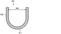
- FIG. 5 is a cross-sectional view showing a cross section of a plunger 30.
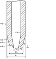
- FIG. FIG. 6 is a cross-sectional view showing a cross-section of a portion of a piston 40. It is explanatory drawing which shows an example of a mode that the suction pump 46 is stopping and driving.
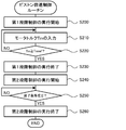
- 7 is a flowchart of an example of a control routine executed by a control device 60. It is a flow chart which shows an example of a piston advance control routine. It is explanatory drawing which shows the mode of the torque of the motor 51 at the time of performing 1st experiment.
- FIG. 1 is a schematic view showing the configuration of a sealing material discharge apparatus 20 according to an embodiment of the present invention
- FIG. 2 is a cross sectional view showing a cross section of a plunger 30, and
- FIG. It is sectional drawing which shows the cross section of a part (tip side).
- the sealant discharge device 20 includes a cartridge 22 with a plunger and a cartridge 22 with a plunger (cartridge 24) in which the sealant 24 is filled in the cartridge 24 and sealed by the plunger 30.
- a movement mechanism 50 for moving the piston 40 in the axial direction of the cartridge 22 with plunger (cartridge 24), and a control device 60 for controlling the entire apparatus.
- the cartridge 22 with a plunger for example, a commercially available product is used.
- the sealant discharge device 20 is used to seal a desired sealing area such as a joint of a fuel tank mounted on an aircraft.
- the sealant discharge device 20 may be used for sealing a desired sealing range other than a fuel tank in the aircraft industry, or may be used for sealing a sealing desired range in an industry other than the aircraft industry.
- the cartridge 24 is made of, for example, polypropylene, polyethylene, nylon or the like.
- the cartridge 24 is formed in a bottomed cylindrical shape with one end side (the upper side in FIG. 1) open, and is a hemispherical bottom portion 25 having a hole in the center and the cartridge 24 from the periphery of the hole in the outer surface of the bottom portion 25.
- the nozzle attachment portion 26 extending in the axial direction (axial direction in FIG. 1), and the cylindrical tubular portion extending from the outer periphery of the bottom portion 25 to the opposite side (upper side in FIG. 1) of the convex side of the bottom portion 25 And 27.
- a nozzle 34 is attached to the nozzle attachment portion 26 of the cartridge 24.
- the nozzle 34 may be of any shape or size depending on the application.
- the plunger 30 is formed so as to be deformable by, for example, an ABS resin or the like. As shown in FIG. 2, the plunger 30 is formed in a bottomed cylindrical shape having one end side (the upper side in FIG. 2) open, and the hemispherical bottom 31 and the convex of the bottom 31 from the outer periphery of the bottom 31. And a cylindrical tubular portion 32 extending to the side opposite to the side (upper side in FIG. 2). The plunger 30 is disposed in the cartridge 24 such that one end side (opening side) of the plunger 30 is on the base end side (upper side in FIG. 1) of the cartridge 24 as shown in FIG. Seal.
- the protective case 38 is made of, for example, stainless steel.
- the protective case 38 is formed in a bottomed cylindrical shape with one end side (upper side in FIG. 1) open, and is hemispherical and has a bottom 38a having a hole in the center and a convex side of the bottom 38a from the outer periphery of the bottom 38a And a cylindrical tubular portion 38b extending to the opposite side.
- the hole of the bottom 38 a is set to a value larger than the outer diameter of the nozzle 34.
- the inner peripheral surfaces of the bottom portion 38 a and the cylindrical portion 38 b are formed to be aligned with the outer peripheral surface of the bottom portion 25 of the cartridge 24 and the cylindrical portion 27.
- the outer diameter of the open end (upper end in FIG. 1) is set to a value smaller than the outer diameter of the other portions, and an external thread is formed on the outer periphery of the open end. It is formed.
- the cartridge 22 with plunger (cartridge 24) described above is inserted into the protective case 38 from the upper side of FIG. At this time, the open end face (upper end face in FIG. 1) of the cylindrical portion 27 of the cartridge 24 and the open end face (upper end face in FIG. 1) of the cylindrical portion 38b of the protective case 38 become flush with each other. There is.
- the protective case 38 is fixed to the base member 21.
- the fixing member 39 includes an annular bottom 39a and an annular wall 39b extending annularly from the outer periphery of the bottom 39a.
- the inner diameter of the annular bottom 39a is set to a value substantially equal to the inner diameter of the cylindrical portion 27 of the cartridge 24, and the outer diameters of the annular bottom 39a and the annular wall 39b are portions of the protective case 38 other than the open end. It is set to a value approximately equal to the outer diameter.
- a female screw that can be screwed to the male screw of the cylindrical portion 38b of the protective case 38 is formed on the inner periphery of the annular wall 39b.
- the fixing member 39 and the protective case 38 are fixed to each other by screwing the female screw of the annular wall 39 b of the fixing member 39 and the male screw of the cylindrical portion 38 b of the protective case 38.
- the annular bottom 39 a of the fixing member 39 can prevent the cartridge 22 with the plunger (cartridge 24) from coming off the protective case 38.
- the piston 40 is made of, for example, an aluminum alloy or the like, and the surface thereof is coated with a fluorocarbon resin such as polytetrafluoroethylene or masked by an adhesive tape of fluorocarbon resin.
- the piston 40 has a through hole 41 penetrating in the axial direction (vertical direction in FIG. 3) as shown in FIG. 3, and at the distal end portion (lower end portion in FIG. 3) It has a taper portion 42 in which the outer diameter gradually decreases from the value R1 to a smaller value R2 toward the side.
- the first tapered portion 43 of the piston 40 has an inclination angle ⁇ 1 with respect to the axial direction of the piston 40, and the outer diameter gradually decreases from the value R1 to a value R3 smaller than that and larger than the value R2.
- a second tapered portion 44 whose outer diameter gradually decreases from the value R3 to the value R2 at an inclination angle ⁇ 2 larger than the inclination angle ⁇ 1 with respect to the axial direction is provided in this order from the base end side of the piston 40.
- the value R1 is set to a value larger than the inner diameter R0 (see FIG. 2) of the cylindrical portion 32 of the plunger 30, and the values R2 and R3 are larger than the inner diameter R0 of the cylindrical portion 32 of the plunger 30.
- the piston 40 is disposed such that the tip end side is on the plunger 30 side (lower side in FIG. 1).
- the axial length (the length in the vertical direction in FIG. 1) of the tapered portion 42 of the piston 40 is made A space can be formed by the plunger 30 and the piston 40 when the inner periphery of the cylindrical portion 32 of the plunger 30 and the tapered portion 42 of the piston 40 are in contact with each other while shortening.
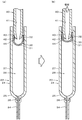
- FIG. 4 is an explanatory view showing an example of a state in which the suction pump 46 is stopped and in operation.
- FIG. 4A shows a state in which the suction pump 46 is stopped
- FIG. 4B shows a state in which the suction pump 46 is in operation. As shown in FIG.
- the outer diameter of the first tapered portion 43 of the piston 40 gradually decreases from a value R1 larger than the inner diameter R0 of the cylindrical portion 32 of the plunger 30 to R3 smaller than the inner diameter R0 toward the tip end side of the piston 40 It is because it has become. In this manner, the periphery of the opening end of the cylindrical portion 32 of the plunger 30 is spread, so that the gap between the outer periphery around the opening end of the cylindrical portion 32 of the plunger 30 and the inner periphery of the cartridge 24 can be narrowed.
- the cartridge 22 with the plunger (the cartridge 24) is inserted into the protective case 38, the radially outer periphery of the open end of the cylindrical portion 32 of the plunger 30 is pushed and spread from the plunger 30 to the cartridge 24. Even if the force is increased, the deformation of the cartridge 24 (the diameter expansion of the portion pressed by the plunger 30) can be suppressed.
- the moving mechanism 50 includes a motor 51, a drive circuit 52 that drives the motor 51 using electric power from an AC power supply (not shown) (for example, an industrial power supply), a reduction gear 53 and a transmission mechanism 54 on the rotation shaft of the motor 51.
- the ball screw 55 connected thereto, the slider 56 screwed to the ball screw 55 and fixed to the piston 40, and the piston 40 and the slider 56 in the axial direction of the cartridge 22 with cartridge (cartridge 24) (upper and lower in FIG. 1) Guide rails 57 for guiding movement in the direction).
- the motor 51, the drive circuit 52, the reduction gear 53, and the guide rail 57 are fixed to the base member 21, and the ball screw 55 is rotatably supported by the base member 21.
- the motor 51 is configured as an AC servomotor, and is rotationally driven by receiving three-phase AC power from the drive circuit 52.
- the drive circuit 52 includes a converter that converts AC power from an AC power supply into DC power, and an inverter that converts DC power from the AC / DC converter into three-phase AC power and supplies the three-phase AC power to the motor 51.
- the transmission mechanism 54 includes a pulley 54a attached to the output side of the reduction gear 53, a pulley 54b attached to one end (upper end in FIG. 1) of the ball screw 55, and a belt 54c wound around the pulley 54a and the pulley 54b. And.
- the ball screw 55 rotates in the first direction via the reduction gear 53 and the transmission mechanism 54, and the slider 56 and the piston 40 move toward the tip end of the cartridge 24 (FIG. Move to the middle, down).
- the motor 51 rotates in the second direction opposite to the first direction
- the ball screw 55 rotates in the second direction opposite to the first direction via the reduction gear 53 and the transmission mechanism 54
- the slider 56 and the piston 40 moves to the side (upper side in FIG. 1) away from the cartridge 24.
- the rotation in the first direction of the motor 51 and the ball screw 55 is referred to as “positive rotation”
- the rotation in the second direction is referred to as “negative rotation”.
- the control device 60 is configured as a computer having a CPU, a ROM, a RAM, an input / output port, and the like.
- the control device 60 receives signals from the input device 70 for the operator to give various instructions, and signals from various sensors (for example, the motor 51 from the rotational position sensor 51a that detects the rotational position of the rotor of the motor 51).
- the rotational position ⁇ m of the rotor and the phase current Iu, Iv, Iw, etc. of each phase from the current sensor 51b flowing in each phase of the motor 51 are input through the input port.
- the control device 60 outputs a control signal to the suction pump 46, a control signal to the drive circuit 52, and the like via an output port.
- As the input device 70 various switches, a keyboard, a mouse, etc. can be mentioned.
- the sealing material discharge device 20 is a cartridge with a plunger 22 attached with a protective case 38, and is used by being attached to the device main body.
- the cartridge without the protective case 38, that is, the cartridge 22 with a plunger may be directly attached to the apparatus main body.
- the sealing material discharge device 20 of the embodiment configured in this way in particular, the operation when sealing the sealing desired range such as a joint of a fuel tank mounted on an aircraft using the sealing material discharge device 20 explain.
- the base member 21 of the sealing material discharge device 20 is attached to a position adjustment device (not shown) such as a robot arm, and the position adjustment device (position of the nozzle 34) of the base member 21 is adjusted by this position adjustment device. It was a thing.
- This position adjustment device is also controlled by the control device 60.
- the operator When sealing the desired sealing area, the operator operates the input device 70 to set the desired sealing area (for example, the start position and the end position, the path from the start position to the end position), and the sealing start (the sealing The discharge start of the material 28 is instructed. Then, when the start of sealing is instructed, the control device 60 controls the position adjusting device to adjust the position of the base member 21 so that the nozzle 34 faces the start position of the desired sealing range, and thereafter, FIG. Execute the control routine of
- the controller 60 starts driving the suction pump 46 (step S100), and thereafter moves (advances) the piston 40 to the distal end side of the cartridge 24
- the execution is started (step S110).
- the piston advance control is performed by controlling the drive circuit 52 so that the motor 51 rotates forward. The details of the piston advance control will be described later.
- the motor 51 is rotated forward, the ball screw 55 rotates forward, and the slider 56 and the piston 40 move to the front end side of the cartridge 24 (downward in FIG. 1).
- the plunger 30 is pushed toward the front end side of the cartridge 24 by the piston 40, and the sealing material 28 in the cartridge 24 is pushed toward the front end side of the cartridge 24 by the plunger 30 and discharged from the nozzle 34.
- the suction end of the cylindrical portion 32 of the plunger 30 is pushed and spread by the suction of the plunger 30 by the suction pump 46, and the outer circumference and the inner circumference of the cartridge 24 near the open end of the cylindrical portion 32 of the plunger 30.
- the relationship between the movement amount of the plunger 30 and the actual discharge flow rate of the sealing material 28 from the nozzle 34 can be made closer to an ideal relationship, and the deviation between the desired discharge flow rate and the actual discharge flow rate can be further reduced. be able to.
- the sealing accuracy the accuracy of the thickness and the width of the sealing material 28
- the deviation between the desired discharge flow rate and the actual discharge flow rate is further reduced. The significance is great.
- the surface of the piston 40 is coated with a fluorine resin or masked by a fluorine resin adhesive tape, even when the sealing material 28 leaks from the gap, when cleaning the piston 40, The cleaning can be facilitated.
- the position adjusting device is controlled to move the base member 21 so that the nozzle 34 moves along the extending direction of the desired sealing range. Thereby, sealing can be performed along the extension direction of the sealing desired range.
- step S120 it is determined whether or not the sealing completion condition (discharge stopping condition of the sealing material 28) is satisfied (step S120), and when it is determined that the sealing completion condition is not satisfied, the above-described piston advancing control is executed. While waiting for the ceiling end condition to be met.
- the sealing end condition for example, a condition in which the nozzle 34 is opposed to the end position of the sealing desired range or a condition in which the sealing end is instructed by the operation of the input device 70 by the operator can be mentioned.
- step S120 When the sealing end condition is satisfied in step S120, the execution of the piston advancing control is ended (step S130), and the piston retraction control for moving (retracting) the piston 40 by a predetermined amount L0 to the side separating from the cartridge 24 is executed ( Step S140) After that, the drive of the suction pump 46 is ended (step S150), and this routine is ended.
- the control of the position adjusting device is ended, or the position adjusting device is controlled to move the base member 21 to the standby position.
- the piston retraction control is performed by controlling the drive circuit 52 such that the motor 51 rotates in the negative direction by a predetermined rotation amount S0 corresponding to the predetermined amount L0.
- the motor 51 rotated in the negative direction
- the ball screw 55 rotates in the negative direction
- the slider 56 and the piston 40 move to the side (upper side in FIG. 1) separating from the cartridge 24.
- the plunger 30 since the plunger 30 is attracted toward the piston 40, when the piston 40 moves away from the cartridge 24, the plunger 30 also moves following the piston 40.
- the pressure in the space (the space formed by the cartridge 24 and the plunger 30) filled with the sealing material 28 is reduced compared to the case where the plunger 30 does not move following the piston 40, and from the nozzle 34
- the predetermined amount L0 is different depending on the properties of the sealing material 28 and the like, and the pressure at the space filled with the sealing material 28 can be improved while the removal of the sealing material 28 from the nozzle 34 is stopped.
- the control device 60 first starts execution of the first step control to move (advance) the tip end side of the cartridge 24 at a relatively large predetermined speed V1 (step advance) S200).
- the torque Tm of the motor 51 reaches the threshold Tmref or more during execution of the first step control (steps S210 and S220)
- the execution of the first step control is ended (step S230), and the piston 40 is moved from the predetermined speed V1.
- Execution of the second step control to move (advance) the tip end side of the cartridge 24 at a small predetermined speed V2 is also started (step S240).
- the sealing termination condition discharge termination condition of the sealing material 28
- step S260 the execution of the second stage control is terminated (step S260), and this routine is performed.
- the target rotational speed Nm * of the motor 51 is set so that the piston 40 moves (advances) to the front end side of the cartridge 24 at the predetermined speed V1. This is performed by controlling the drive circuit 52 so as to rotate.
- the target rotational speed Nm * of the motor 51 is set so that the piston 40 moves to the front end side of the cartridge 24 at a predetermined speed V2, and the drive circuit rotates so as to rotate the motor 51 at the target rotational speed Nm * It is done by controlling 52.
- the control of the drive circuit 52 performs pulse width modulation control using the rotational position ⁇ m of the rotor of the motor 51 from the rotational position sensor 51a and the phase currents Iu, Iv, Iw of each phase of the motor 51 from the current sensor 51b It is performed by PWM control.
- the predetermined speeds V1 and V2 the speeds at which the discharge flow rate of the sealing material 28 becomes the desired flow rates Q1 and Q2 when the discharge flow rate of the sealing material 28 from the nozzle 34 is stable are used.
- the desired flow rate Q2 is determined based on the shapes of the cartridge 24 and the nozzle 34, the desired width and the desired thickness of the bead to be applied to the desired sealing range, the moving speed of the base member 21 (nozzle 34) by the position adjustment device, etc.
- Values such as 150 cc / min, 200 cc / min, 250 cc / min, etc. are used.
- a value such as 2 times, 3 times or 4 times the desired flow rate Q2 is used.
- the torque Tm of the motor 51 is estimated based on the rotational position ⁇ m of the rotor of the motor 51 from the rotational position sensor 51a and the phase currents Iu, Iv, Iw of each phase of the motor 51 from the current sensor 51b. .
- the threshold value Tmref is determined as a value larger than the torque Tm (hereinafter referred to as “stable torque Tmst”) when the torque Tm of the motor 51 is stable during execution of the second step control, for example, stable torque Tmst However, large values such as 10%, 20%, and 30% are used.
- the inventor conducted a first experiment using a commercially available cartridge 22 with a plunger.
- the base member 21 nozzle 34
- Vset a predetermined speed Vset by the position adjustment device (see FIG. Only the second stage control was performed while moving in 1) (lateral direction).
- one cartridge 22 with plunger was used per set (20 minutes, 40 minutes, 60 minutes, 80 minutes after thawing of the cartridge 22 with a plunger).
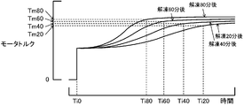
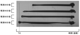
- FIGS. 7 and 8 are explanatory views showing the state of the torque Tm and the bead of the motor 51 when the first experiment is performed, respectively.
- “Ti0” indicates the movement of the piston 40 and the base member 21 (nozzle 34) for 20 minutes, 40 minutes, 60 minutes, and 80 minutes after thawing of the cartridge 22 with a plunger.
- Ti20”, “Ti40”, “Ti60”, “Ti80” are timings at which the bead width Wb becomes stable (becomes stable)
- Tm20”, “Tm40”, Tm60 ′ ′ and “Tm80” are torques when the bead width Wb is stable (becomes stable) (it becomes a torque equivalent to the above-mentioned stable torque Tmst).
- the bead 20 minutes after thawing of the cartridge 22 with the plunger is shortest (the time (distance) from the timing Ti0 until the bead starts to be formed is the longest). It is considered that it takes time for the nozzle 34 to be discharged from the nozzle 34.
- the reason why the width Wb is relatively large at the bead start position after 40 minutes, 60 minutes, and 80 minutes after thawing of the cartridge 22 with a plunger is the sealant remaining in the nozzle 34 at the end of the previous cycle. It is considered that 28 (residue) was discharged.
- the motor 51 is started according to the lapse of time from the start of the movement of the piston 40 at 20 minutes, 40 minutes, 60 minutes, and 80 minutes after thawing the cartridge 22 with plungers.
- the torque Tm and the bead width Wb are increased to be stable.
- the torque Tm of the motor 51 and the width Wb of the bead reach stability in a short time and the stable torque Tmst of the motor 51 increases as the time from thawing of the cartridge 22 with a plunger becomes longer. This is considered to be because the viscosity of the sealing material 28 increases as the time from thawing increases.
- the inventor conducted a second experiment using a commercially available cartridge 22 with a plunger.
- the base member 21 nozzle 34
- the 1st step control and the 2nd step control were sequentially performed while moving to 1) (in the lateral direction) (the piston advance control routine in FIG. 6 was performed).
- one cartridge 22 with plunger was used per set (20 minutes after thawing of the cartridge 22 with a plunger, 40 minutes after, 60 minutes after, 80 minutes after) .
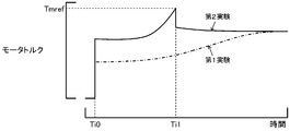
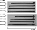
- FIGS. 9 and 10 are explanatory views showing the state of the torque Tm and the bead of the motor 51 when the second experiment and the first experiment are performed, respectively.
- “Ti0” is the timing at which the movement of the piston 40 and the base member 21 (nozzle 34) is started
- Ti1 is the first one when the torque Tm of the motor 51 in the second experiment reaches the threshold Tmref or more. This is the timing at which the stage control is switched to the second stage control.
- the torque Tm of the motor 51 increases more rapidly in the case of the second experiment than in the first experiment, and the torque Tm of the motor 51 stabilizes quickly from the start of the second stage control.
- the bead width Wb is more constant in the second experiment than in the first experiment.
- the first step control is executed by switching from the first step control to the second step control when the torque Tm of the motor 51 reaches or exceeds the threshold value Tmref while the first step control is executed.
- the torque Tm of the motor 51 and the width Wb of the bead can be stabilized more quickly from the start of the execution of the second stage control than in the case where the second stage control is executed from the beginning. Therefore, even if the switching timing to switch from the first stage control to the second stage control is determined not by the movement amount of the piston 40 based on the remaining amount or viscosity of the cartridge 24 but by the torque Tm (threshold Tmref) of the motor 51, It can be said that it can be determined.
- the pressure in the space filled with the sealing material 28 (the space formed by the cartridge 24 and the plunger 30) can be rapidly increased by executing the first stage control before executing the second stage control. And the time (distance) in which the bead width Wb gradually increases can be shortened or almost none. Then, since the torque Tm of the motor 51 is estimated using sensors (rotational position sensor 51a and current sensor 51b) necessary for controlling the motor 51, there is no need to provide a dedicated sensor for estimation of the torque Tm of the motor 51. The increase in the number of sensors can be suppressed.
- the first stage control when discharging the sealing material 28 from the nozzle 34, the first stage control is executed, and the torque Tm of the motor 51 reaches or exceeds the threshold value Tmref during the execution.
- Execute second stage control As described above, by switching from the first stage control to the second stage control when the torque Tm of the motor 51 reaches the threshold Tmref or more, the second stage is compared to the case where the second stage control is performed from the beginning, It is possible to stabilize the discharge flow rate of the sealing material 28 from the nozzle 34 (the width of the bead) quickly from the start of control execution. Therefore, even if the switching timing is determined not by the movement amount of the piston 40 but by the torque Tm (threshold Tmref) of the motor 51, it can be said that the switching timing can be set appropriately.
- a uniform value is used as the threshold value Tmref, but based on the elapsed time from thawing of the cartridge 22 with a plunger, the remaining amount of the sealing material 28 in the cartridge 24, etc. It may be set.
- Tmref based on the elapsed time from thawing of the cartridge 22 with plunger, in consideration of the fact that the stable torque Tmst of the motor 51 becomes larger as the time from thawing of the cartridge with plunger 22 becomes longer (see FIG. 7). It is conceivable to set the threshold value Tmref so that the longer the time from the thawing of the cartridge 22 with the plunger, the longer it becomes.
- the torque Tm of the motor 51 is determined by the rotational position ⁇ m of the rotor of the motor 51 from the rotational position sensor 51a and the phase current Iu, Iv, of each phase of the motor 51 from the current sensor 51b.
- Iw the phase current Iu, Iv, of each phase of the motor 51 from the current sensor 51b.
- the alternating current servomotor is used as the motor 51 in the sealing material discharge device 20 of the embodiment, the present invention is not limited to this, and another motor may be used.
- the sealing material discharge device 20 of the embodiment a material which requires freezing storage and which becomes high in viscosity (hardened) as time passes after thawing is used as the sealing material 28.
- a material which can be stored at normal temperature and whose viscosity becomes higher (hardened) as time passes after discharge from the nozzle 34 (when it is exposed to air) such as epoxy resin or polyurethane. It is also good.
- the bottom portion 31 of the plunger 30 is formed in a hemispherical shape, but is not limited to this shape, and is formed, for example, in a truncated cone shape It is also good.
- the plunger 30 shall be formed in the bottomed cylindrical shape which has the bottom part 31 and the cylindrical part 32, it is not limited to this shape, For example, it does not have the cylindrical part 32. It may be formed in a hemispherical shape having only the bottom portion 31 or a cylindrical shape.
- the tapered portion 42 of the piston 40 is provided with the first tapered portion 43 and the second tapered portion 44, but may be provided with only the first tapered portion 43. Further, although the piston 40 is provided with the tapered portion 42, the piston 40 may not be provided with the tapered portion 42.
- the surface of the piston 40 is coated with a fluorine resin or masked with a pressure sensitive adhesive tape of fluorine resin, but the coating with fluorine resin and the mask with pressure sensitive adhesive tape of fluorine resin are also You may not want to
- the cartridge 24 with the plunger filled with the sealing material 28 in the cartridge 24 and sealed by the plunger 30, the piston 40, and the suction pump 46 are provided.
- the plunger 30 of the cartridge 22 with a plunger and the piston 40 may be integrated by bonding or the like.
- the transmission mechanism 54 is stretched around the pulley 54a attached to the output side of the reduction gear 53, the pulley 54b attached to one end of the ball screw 55, and the pulley 54a and the pulley 54b.
- Belt 54c and comprises a first gear attached to the output side of the reduction gear 53, and a second gear attached to one end of the ball screw 55 and meshing with the first gear. It is also good.
- the moving mechanism 50 connects the rotation shaft of the motor 51 and the ball screw 55 via the reduction gear 53 and the transmission mechanism 54, but (A) the reduction gear 53 and the transmission The rotating shaft of the motor 51 and the ball screw 55 may be connected without the mechanism 54. (B) The rotating shaft of the motor 51 with the ball screw 55 only via the reduction gear 53 without the transmission mechanism 54. And (C) the rotation shaft of the motor 51 and the ball screw 55 may be connected only via the transmission mechanism 54 without the reduction gear 53. In the case of (A) or (B), it is considered that the rotation shaft of the motor 51 and the ball screw 55 may be disposed coaxially.
- the cartridge 24 corresponds to a "cartridge”
- the sealing material 28 corresponds to a “sealing material”
- the piston 40 corresponds to a "piston”
- the nozzle 34 corresponds to a "nozzle”
- the moving mechanism 50 The control device 60 corresponds to "control means”.
- the correspondence between the main elements of the embodiment and the main elements of the invention described in the section of the summary of the invention specifically indicates the embodiments for implementing the invention described in the section of the summary of the invention.
- the invention is not limited to the elements of the invention described in the section of the summary of the invention, as it is an example to illustrate. That is, the interpretation of the invention described in the section of the summary of the invention should be made based on the description of the section, and the embodiment is only a specific example of the invention described in the section of the summary of the invention. It is.
- the present invention is applicable to the manufacturing industry of a sealing material discharge apparatus and the like.
Landscapes
- Coating Apparatus (AREA)
Abstract
筒状のカートリッジ内のシーリング材をピストンによって押圧することによりシーリング材をカートリッジの先端に設けられたノズルから吐出するシーリング材吐出装置であって、モータの回転によりピストンをカートリッジの軸方向に移動させる移動手段と、シーリング材をノズルから吐出させる際、ピストンが第1速度でカートリッジの先端側に移動するようにモータを制御する第1段階制御を実行し、第1段階制御の実行中にモータのトルクが閾値よりも大きくなると、ピストンが第1速度よりも遅い第2速度でカートリッジの先端側に移動するようにモータを制御する第2段階制御を実行する。
Description
本発明は、シーリング材吐出装置およびシーリング材吐出装置本体に関する。
従来、この種のシーリング材吐出装置としては、カートリッジ内のシーリング材をピストン軸の先端部に設けられたプッシャーによって押圧することによりカートリッジに設けられたノズルから吐出するシーリング材吐出装置において、ピストン軸に接続されたスライダが設置されたボールねじにモータが接続されており、モータの回転に応じてピストン軸およびプッシャーが一体に軸方向に移動するものが提案されている(例えば、特許文献1参照)。このシーリング材吐出装置では、シーリング材の吐出開始の指令を受けると、第1期間において、第1速度でピストン軸をシーリング材の吐出方向に移動させた後に、第2期間において、第1速度よりも遅い第2速度でピストン軸をシーリング材の吐出方向に移動させる。これにより、第1期間においてカートリッジ内のシーリング材に圧力(予圧)をかけることができ、第1期間の終了後に速やかにシーリング材の吐出を開始させることができると共にその後に一定流量でシーリング材を吐出させ続けることができる。ここで、第1期間は、カートリッジに充填されているシーリング材の残量や粘度に基づくピストン軸の移動量として定められる。
こうしたシーリング材吐出装置では、ノズルから吐出される紐状のシーリング材(ビード)の幅をできるだけ一定にするために、ピストン軸(ピストン)の移動速度を第1速度からそれよりも遅い第2速度に切り替える切替タイミングをどのように定めるかが課題となっている。上述のシーリング材吐出装置では、この切替タイミングを、シーリング材の残量や粘度に基づくピストン軸の移動量として定めているものの、ピストン軸の移動量とは異なるパラメータにより定めることも、技術の向上のために有用である。
本発明のシーリング材吐出装置およびシーリング材吐出装置本体は、ピストンの移動速度を第1速度からそれよりも遅い第2速度に切り替える切替タイミングをピストンの移動量とは異なるパラメータにより定めることを主目的とする。
本発明のシーリング材吐出装置およびシーリング材吐出装置本体は、上述の主目的を達成するために以下の手段を採った。
本発明のシーリング材吐出装置は、
筒状のカートリッジ内のシーリング材をピストンによって押圧することにより前記シーリング材を前記カートリッジの先端に設けられたノズルから吐出するシーリング材吐出装置であって、
モータの回転により前記ピストンを前記カートリッジの軸方向に移動させる移動手段と、
前記シーリング材を前記ノズルから吐出させる際、前記ピストンが第1速度で前記カートリッジの先端側に移動するように前記モータを制御する第1段階制御を実行し、前記第1段階制御の実行中に前記モータのトルクが閾値よりも大きくなると、前記ピストンが前記第1速度よりも遅い第2速度で前記カートリッジの先端側に移動するように前記モータを制御する第2段階制御を実行する制御手段と、
を備えることを要旨とする。
筒状のカートリッジ内のシーリング材をピストンによって押圧することにより前記シーリング材を前記カートリッジの先端に設けられたノズルから吐出するシーリング材吐出装置であって、
モータの回転により前記ピストンを前記カートリッジの軸方向に移動させる移動手段と、
前記シーリング材を前記ノズルから吐出させる際、前記ピストンが第1速度で前記カートリッジの先端側に移動するように前記モータを制御する第1段階制御を実行し、前記第1段階制御の実行中に前記モータのトルクが閾値よりも大きくなると、前記ピストンが前記第1速度よりも遅い第2速度で前記カートリッジの先端側に移動するように前記モータを制御する第2段階制御を実行する制御手段と、
を備えることを要旨とする。
この本発明のシーリング材吐出装置では、シーリング材をノズルから吐出させる際、ピストンが第1速度でカートリッジの先端側に移動するようにモータを制御する第1段階制御を実行し、第1段階制御の実行中にモータのトルクが閾値よりも大きくなると、ピストンが第1速度よりも遅い第2速度でカートリッジの先端側に移動するようにモータを制御する第2段階制御を実行する。即ち、第1段階制御から第2段階制御に切り替える切替タイミングをモータのトルクで定めるのである。このように、モータのトルクが閾値以上に至ったときに第1段階制御から第2段階制御に切り替えることにより、最初から第2段階制御を実行するものに比して、第2段階制御の実行開始から迅速にノズルからのシーリング材の吐出流量(ビードの幅)を安定させることができる。この効果を奏することを、本発明者は、実験により確認した。したがって、切替タイミングをピストンの移動量でなくモータのトルクで定めても、切替タイミングを適切に設定可能であると言える。
こうした本発明のシーリング材吐出装置において、前記閾値は、前記第2段階制御の実行中に前記モータのトルク値が安定しているときの前記トルク値よりも大きい値であるものとしてもよい。こうすれば、第2段階制御の実行開始からより迅速にシーリング材の吐出流量(ビードの幅)およびモータのトルクを安定させることができる。
また、本発明のシーリング材吐出装置において、前記シーリング材には、解凍後に時間の経過に従って硬化する材料が用いられており、前記閾値は、前記シーリング材の解凍からの時間が長いほど大きくなる傾向に設定されるものとしてもよい。これは、本発明者が実験により解凍後の時間が長いほどノズルからのシーリング材の吐出流量(ビードの幅)およびモータのトルクが安定しているときのモータのトルクの値が大きくなることを見出したためである。
さらに、本発明のシーリング材吐出装置において、前記モータは、三相交流電力により駆動される交流サーボモータであり、前記制御手段は、前記モータに取り付けられた回転位置センサおよび電流センサにより検出される回転子の回転位置および各相の相電流を用いて前記モータを制御し、更に、前記回転子の回転位置および前記相電流を用いて前記モータのトルクを推定するものとしてもよい。こうすれば、モータのトルクの推定用に専用のセンサを設ける必要がないから、センサ数の増加を抑制することができる。
本発明のシーリング材吐出装置本体は、
筒状のカートリッジ内にシーリング材が充填されてプランジャにより封止されたプランジャ付カートリッジが装着され、前記プランジャ付カートリッジ内の前記シーリング材をピストンによって押圧することにより前記シーリング材を前記カートリッジの先端に設けられたノズルから吐出させるシーリング材吐出装置であって、
モータの回転により前記ピストンを前記カートリッジの軸方向に移動させる移動手段と、
前記シーリング材を前記ノズルから吐出させる際、前記ピストンが第1速度で前記カートリッジの先端側に移動するように前記モータを制御する第1段階制御を実行し、前記第1段階制御の実行中に前記モータのトルクが閾値よりも大きくなると、前記ピストンが前記第1速度よりも遅い第2速度で前記カートリッジの先端側に移動するように前記モータを制御する第2段階制御を実行する制御手段と、
を備えることを要旨とする。
筒状のカートリッジ内にシーリング材が充填されてプランジャにより封止されたプランジャ付カートリッジが装着され、前記プランジャ付カートリッジ内の前記シーリング材をピストンによって押圧することにより前記シーリング材を前記カートリッジの先端に設けられたノズルから吐出させるシーリング材吐出装置であって、
モータの回転により前記ピストンを前記カートリッジの軸方向に移動させる移動手段と、
前記シーリング材を前記ノズルから吐出させる際、前記ピストンが第1速度で前記カートリッジの先端側に移動するように前記モータを制御する第1段階制御を実行し、前記第1段階制御の実行中に前記モータのトルクが閾値よりも大きくなると、前記ピストンが前記第1速度よりも遅い第2速度で前記カートリッジの先端側に移動するように前記モータを制御する第2段階制御を実行する制御手段と、
を備えることを要旨とする。
この本発明のシーリング材吐出装置本体では、シーリング材をノズルから吐出させる際、ピストンが第1速度でカートリッジの先端側に移動するようにモータを制御する第1段階制御を実行し、第1段階制御の実行中にモータのトルクが閾値よりも大きくなると、ピストンが第1速度よりも遅い第2速度でカートリッジの先端側に移動するようにモータを制御する第2段階制御を実行する。即ち、第1段階制御から第2段階制御に切り替える切替タイミングをモータのトルクで定めるのである。このように、モータのトルクが閾値以上に至ったときに第1段階制御から第2段階制御に切り替えることにより、最初から第2段階制御を実行するものに比して、第2段階制御の実行開始から迅速にノズルからのシーリング材の吐出流量(ビードの幅)を安定させることができる。この効果を奏することを、本発明者は、実験により確認した。したがって、切替タイミングをピストンの移動量でなくモータのトルクで定めても、切替タイミングを適切に設定可能であると言える。
次に、本発明を実施するための形態を実施例を用いて説明する。
図1は、本発明の一実施例としてのシーリング材吐出装置20の構成の概略を示す構成図であり、図2は、プランジャ30の断面を示す断面図であり、図3は、ピストン40の一部(先端側)の断面を示す断面図である。
シーリング材吐出装置20は、図1に示すように、カートリッジ24内にシーリング材(シーラント)28が充填されてプランジャ30により封止されたプランジャ付カートリッジ22と、プランジャ付カートリッジ22(カートリッジ24)を保護する保護ケース38と、プランジャ30をカートリッジ24の先端側(図1中、下側)に押圧可能なピストン40と、プランジャ30をピストン40側(図1中、上側)に吸引する吸引ポンプ46と、ピストン40をプランジャ付カートリッジ22(カートリッジ24)の軸方向に移動させる移動機構50と、装置全体の制御を行なう制御装置60と、を備える。ここで、プランジャ付カートリッジ22としては、例えば市販品が用いられる。このシーリング材吐出装置20は、航空機に搭載される燃料タンクの接合部などのシーリング所望範囲のシーリングに用いられる。なお、このシーリング材吐出装置20は、航空機産業における燃料タンク以外のシーリング所望範囲のシーリングに用いられるものとしてもよいし、航空機産業以外の産業におけるシーリング所望範囲のシーリングに用いられるものとしてもよい。
カートリッジ24は、例えば、ポリプロピレンやポリエチレン、ナイロンなどによって形成されている。このカートリッジ24は、一端側(図1中、上側)が開口する有底筒状に形成されており、半球状で中央に孔を有する底部25と、底部25の外面における孔の周囲からカートリッジ24の軸方向(図1中、軸方向)に延出するノズル取付部26と、底部25の外周から底部25の凸側とは反対側(図1中、上側)に延びる筒状の筒状部27と、を備える。カートリッジ24のノズル取付部26には、ノズル34が取り付けられている。このノズル34は、用途に応じた形状や大きさのものが用いられる。
シーリング材28としては、冷凍保存が必要で且つ解凍後に時間の経過に従って粘度が高くなる(硬化する)材料、例えば、シリコン樹脂などが用いられる。プランジャ30は、例えばABS樹脂などによって変形可能に形成されている。このプランジャ30は、図2に示すように、一端側(図2中、上側)が開口する有底筒状に形成されており、半球状の底部31と、底部31の外周から底部31の凸側とは反対側(図2中、上側)に延びる筒状の筒状部32と、を備える。このプランジャ30は、図1に示すように、一端側(開口側)がカートリッジ24の基端側(図1中、上側)となるようにカートリッジ24内に配置され、カートリッジ24内にシーリング材28を封止する。
保護ケース38は、例えば、ステンレスなどによって形成されている。この保護ケース38は、一端側(図1中、上側)が開口する有底筒状に形成されており、半球状で中央に孔を有する底部38aと、底部38aの外周から底部38aの凸側とは反対側に延びる筒状の筒状部38bと、を備える。底部38aの孔は、ノズル34の外径よりも大きい値に定められている。底部38aや筒状部38bの内周面は、カートリッジ24の底部25や筒状部27の外周面に整合するように形成されている。筒状部38bにおいて、開口端部(図1中、上端部)の外径は、それ以外の部分の外径よりも小さい値に定められており、開口端部の外周には、雄ねじ部が形成されている。上述のプランジャ付カートリッジ22(カートリッジ24)は、この保護ケース38に図1の上側から挿入される。このとき、カートリッジ24の筒状部27の開口端面(図1中、上端面)と、保護ケース38の筒状部38bの開口端面(図1中、上端面)と、は面一になっている。保護ケース38は、ベース部材21に固定される。
固定部材39は、環状の環状底部39aと、環状底部39aの外周部から環状で延出する環状壁部39bと、を備える。環状底部39aの内径は、カートリッジ24の筒状部27の内径に略等しい値に定められており、環状底部39aや環状壁部39bの外径は、保護ケース38における開口端部以外の部分の外径に略等しい値に定められている。環状壁部39bの内周には、保護ケース38の筒状部38bの雄ねじ部に螺合可能な雌ねじ部が形成されている。固定部材39と保護ケース38とは、固定部材39の環状壁部39bの雌ねじ部と保護ケース38の筒状部38bの雄ねじ部との螺合により、互いに固定される。そして、固定部材39の環状底部39aにより、プランジャ付カートリッジ22(カートリッジ24)が保護ケース38から抜けるのを抑止することができる。
ピストン40は、例えば、アルミニウム合金などによって形成されており、その表面は、ポリテトラフルオロエチレンなどのフッ素樹脂によりコーティングされたり、フッ素樹脂の粘着テープによりマスクされたりしている。このピストン40は、図3に示すように、その軸方向(図3中、上下方向)に貫通する貫通孔41を有すると共に、先端部(図3中、下端部)に、基端側から先端側に向かうにつれて外径が値R1からそれよりも小さい値R2まで徐々に小さくなるテーパ部42を有する。テーパ部42は、ピストン40の軸方向に対して傾斜角度θ1で外径が値R1からそれよりも小さく且つ値R2よりも大きい値R3まで徐々に小さくなる第1テーパ部43と、ピストン40の軸方向に対して傾斜角度θ1よりも大きい傾斜角度θ2で外径が値R3から値R2まで徐々に小さくなる第2テーパ部44と、をピストン40の基端側からこの順に有する。ここで、値R1は、プランジャ30の筒状部32の内径R0(図2参照)よりも大きい値に定められており、値R2,R3は、プランジャ30の筒状部32の内径R0よりも小さい値に定められている。このピストン40は、図1に示すように、先端側がプランジャ30側(図1中、下側)となるように配置される。ピストン40の第2テーパ部44の傾斜角度θ2を第1テーパ部43の傾斜角度θ1よりも大きくすることにより、ピストン40のテーパ部42の軸長(図1中、上下方向の長さ)を短くしつつ、プランジャ30の筒状部32の内周とピストン40のテーパ部42とが当接しているときにプランジャ30とピストン40とにより空間を形成することができる。
吸引ポンプ46は、図1に示すように、ピストン40の基端(図1中、上端)における貫通孔41に整合する位置に取り付けられており、ピストン40の貫通孔41を介してプランジャ30を吸引できるようになっている。図4は、吸引ポンプ46の停止中および駆動中の様子の一例を示す説明図である。図4(a)は、吸引ポンプ46の停止中の様子を示し、図4(b)は、吸引ポンプ46の駆動中の様子を示す。図4(a)に示すように、プランジャ30の筒状部32の内周とピストン40のテーパ部42とが当接している状態で、吸引ポンプ46の駆動を開始すると、ピストン40の貫通孔41を介して、プランジャ30とピストン40とにより形成される空間が減圧され、図4(b)に示すように、プランジャ30の底部31が半球状からつぶれて筒状部32が広がると共に、プランジャ30の筒状部32の開口端周辺がピストン40の第1テーパ部43に沿って押し広げられる。後者は、ピストン40の第1テーパ部43の外径が、ピストン40の先端側に向かうにつれてプランジャ30の筒状部32の内径R0よりも大きい値R1から内径R0よりも小さいR3まで徐々に小さくなっているためである。こうしてプランジャ30の筒状部32の開口端周辺が押し広げられることにより、プランジャ30の筒状部32の開口端周辺の外周とカートリッジ24の内周との隙間をより狭くすることができる。また、プランジャ付カートリッジ22(カートリッジ24)は保護ケース38に挿通されているから、プランジャ30の筒状部32の開口端周辺が押し広げられてプランジャ30からカートリッジ24に作用する径方向外向きの力が大きくなっても、カートリッジ24の変形(プランジャ30により押圧される部分の拡径)を抑制することができる。
移動機構50は、モータ51と、図示しない交流電源(例えば工業用電源など)からの電力を用いてモータ51を駆動する駆動回路52と、モータ51の回転軸に減速機53および伝達機構54を介して連結されたボールネジ55と、ボールネジ55に螺合されると共にピストン40に固定されたスライダ56と、ピストン40およびスライダ56がプランジャ付カートリッジ22(カートリッジ24)の軸方向(図1中、上下方向)に移動するのをガイドするガイドレール57と、を備える。モータ51や駆動回路52、減速機53、ガイドレール57は、ベース部材21に固定されており、ボールネジ55は、ベース部材21により回転自在に支持されている。
ここで、モータ51は、交流サーボモータとして構成されており、駆動回路52からの三相交流電力を受けて回転駆動される。駆動回路52は、交流電源からの交流電力を直流電力に変換するコンバータや、AC/DC変換器からの直流電力を三相交流電力に変換してモータ51に供給するインバータを備える。伝達機構54は、減速機53の出力側に取り付けられたプーリ54aと、ボールネジ55の一端(図1中、上端)に取り付けられたプーリ54bと、プーリ54aおよびプーリ54bに掛け渡されたベルト54cと、を備える。
この移動機構50では、モータ51が第1方向に回転すると、減速機53や伝達機構54を介してボールネジ55が第1方向に回転し、スライダ56およびピストン40がカートリッジ24の先端側(図1中、下側)に移動する。また、モータ51が第1方向とは反対の第2方向に回転すると、減速機53および伝達機構54を介してボールネジ55が第1方向とは反対の第2方向に回転し、スライダ56およびピストン40がカートリッジ24から離間する側(図1中、上側)に移動する。以下、モータ51やボールネジ55の第1方向の回転を「正回転」といい、第2方向の回転を「負回転」という。
制御装置60は、CPUやROM、RAM、入出力ポートなどを有するコンピュータとして構成されている。制御装置60には、操作者が各種指示を行なうための入力装置70からの信号や、各種センサからの信号(例えば、モータ51の回転子の回転位置を検出する回転位置センサ51aからのモータ51の回転子の回転位置θmや、モータ51の各相に流れる電流センサ51bからの各相の相電流Iu,Iv,Iwなど)が入力ポートを介して入力されている。制御装置60からは、吸引ポンプ46への制御信号や駆動回路52への制御信号などが出力ポートを介して出力されている。入力装置70としては、各種スイッチや、キーボード、マウスなどを挙げることができる。
ここで、シーリング材吐出装置20では、プランジャ付カートリッジ22や保護ケース38を除く部分、具体的には、ピストン40や吸引ポンプ46、移動機構50、ベース部材21、制御装置60が装置本体に相当する。そして、シーリング材吐出装置20は、プランジャ付カートリッジ22に保護ケース38が取り付けられたものが装置本体に取り付けられて用いられる。なお、保護ケース38を用いないもの、即ち、プランジャ付カートリッジ22が装置本体に直接取り付けられるものとしてもよい。
次に、こうして構成された実施例のシーリング材吐出装置20の動作、特に、航空機に搭載される燃料タンクの接合部などのシーリング所望範囲をシーリング材吐出装置20を用いてシーリングする際の動作について説明する。なお、実施例では、シーリング材吐出装置20のベース部材21は、ロボットアームなどの図示しない位置調節装置に取り付けられ、この位置調節装置によりベース部材21の位置(ノズル34の位置)が調節されるものとした。この位置調節装置も、制御装置60により制御されるものとした。
シーリング所望範囲をシーリングする際には、操作者による入力装置70の操作により、シーリング所望範囲(例えば、開始位置および終了位置や、開始位置から終了位置までの経路)が設定され、シーリング開始(シーリング材28の吐出開始)が指示される。そして、制御装置60は、シーリング開始が指示されると、位置調節装置を制御して、ノズル34がシーリング所望範囲の開始位置に対向するようにベース部材21の位置を調節し、その後に図5の制御ルーチンを実行する。
図5の制御ルーチンが実行されると、制御装置60は、吸引ポンプ46の駆動を開始し(ステップS100)、その後にピストン40をカートリッジ24の先端側に移動させる(前進させる)ピストン前進制御の実行を開始する(ステップS110)。このピストン前進制御は、モータ51が正回転するように駆動回路52を制御することにより行なわれる。なお、ピストン前進制御の詳細については後述する。モータ51を正回転させると、ボールネジ55が正回転し、スライダ56およびピストン40がカートリッジ24の先端側(図1中、下側)に移動する。この際に、ピストン40によりプランジャ30がカートリッジ24の先端側に押圧され、プランジャ30によりカートリッジ24内のシーリング材28がカートリッジ24の先端側に押圧されてノズル34から吐出される。実施例では、吸引ポンプ46によるプランジャ30の吸引により、プランジャ30の筒状部32の開口端周辺が押し広げられて、プランジャ30の筒状部32の開口端付近の外周とカートリッジ24の内周との隙間がより狭くなっているから、プランジャ30がカートリッジ24の先端側に移動する際に、この隙間からシーリング材28が漏れるのをより抑制することができる。これにより、プランジャ30の移動量とノズル34からのシーリング材28の実吐出流量との関係をより理想的な関係に近づけることができ、所望の吐出流量と実吐出流量とのズレをより小さくすることができる。特に、航空機の製造産業などでは、シーリング所望範囲のシーリング精度(シーリング材28の厚みや幅の精度)が要求されることから、所望の吐出流量と実吐出流量とのズレをより小さくすることの意義が大きい。また、実施例では、ピストン40の表面がフッ素樹脂によりコーティングされている或いはフッ素樹脂の粘着テープによりマスクされているから、隙間からシーリング材28が漏れたときでも、ピストン40を清掃する際に、その清掃を容易にすることができる。
このようにしてノズル34からシーリング材28を吐出させる際には、位置調節装置を制御して、ノズル34がシーリング所望範囲の延在方向に沿って移動するようにベース部材21を移動させる。これにより、シーリング所望範囲の延在方向に沿ってシーリングを行なうことができる。
続いて、シーリング終了条件(シーリング材28の吐出停止条件)が成立したか否かを判定し(ステップS120)、シーリング終了条件が成立していないと判定したときには、上述のピストン前進制御を実行しながらシーリング終了条件が成立するのを待つ。ここで、シーリング終了条件としては、例えば、ノズル34がシーリング所望範囲の終了位置に対向した条件や、操作者による入力装置70の操作によりシーリング終了が指示された条件を挙げることができる。
ステップS120でシーリング終了条件が成立すると、ピストン前進制御の実行を終了し(ステップS130)、ピストン40をカートリッジ24から離間する側に所定量L0だけ移動させる(後退させる)ピストン後退制御を実行し(ステップS140)、その後に吸引ポンプ46の駆動を終了して(ステップS150)、本ルーチンを終了する。なお、シーリング終了条件が成立すると、これらと並行して、位置調節装置の制御を終了する、或いは、位置調節装置を制御してベース部材21を待機位置まで移動させる。
ここで、ピストン後退制御は、モータ51が所定量L0に対応する所定回転量S0だけ負回転するように駆動回路52を制御することにより行なわれる。モータ51を負回転させると、ボールネジ55が負回転し、スライダ56およびピストン40がカートリッジ24から離間する側(図1中、上側)に移動する。実施例では、プランジャ30がピストン40側に吸引されているから、ピストン40がカートリッジ24から離間する側に移動する際には、プランジャ30もピストン40に追従して移動する。これにより、プランジャ30がピストン40に追従して移動しないものに比して、シーリング材28が充填された空間(カートリッジ24とプランジャ30とにより形成される空間)の圧力を低減し、ノズル34からのシーリング材28の吐出を停止する際のキレ(吐出のオンオフの応答性)を良好にすることができる。ここで、所定量L0は、シーリング材28の性状などによって異なるものであり、ノズル34からのシーリング材28の吐出を停止する際のキレを良好にできると共にシーリング材28が充填された空間の圧力が低減しすぎない程度のピストン40の移動量として予め実験や解析により定めた値を用いることができる。
次に、図5の制御ルーチンのピストン前進制御の詳細について、図6のピストン前進制御ルーチンを用いて説明する。図6のピストン前進制御ルーチンでは、制御装置60は、最初に、ピストン40を比較的大きい所定速度V1でカートリッジ24の先端側に移動させる(前進させる)第1段階制御の実行を開始する(ステップS200)。そして、第1段階制御の実行中にモータ51のトルクTmが閾値Tmref以上に至ると(ステップS210,S220)、第1段階制御の実行を終了し(ステップS230)、ピストン40を所定速度V1よりも小さい所定速度V2でカートリッジ24の先端側に移動させる(前進させる)第2段階制御の実行を開始する(ステップS240)。そして、第2段階制御の実行中にシーリング終了条件(シーリング材28の吐出終了条件)が成立すると(ステップS250)、第2段階制御の実行を終了して(ステップS260)、本ルーチンをする。
ここで、第1段階制御は、ピストン40が所定速度V1でカートリッジ24の先端側に移動する(前進する)ようにモータ51の目標回転数Nm*を設定し、モータ51が目標回転数Nm*で回転するように駆動回路52を制御することにより行なわれる。第2段階制御は、ピストン40が所定速度V2でカートリッジ24の先端側に移動するようにモータ51の目標回転数Nm*を設定し、モータ51が目標回転数Nm*で回転するように駆動回路52を制御することにより行なわれる。駆動回路52の制御は、回転位置センサ51aからのモータ51の回転子の回転位置θmと電流センサ51bからのモータ51の各相の相電流Iu,Iv,Iwとを用いてパルス幅変調制御(PWM制御)により行なわれる。所定速度V1,V2は、それぞれ、ノズル34からのシーリング材28の吐出流量が安定しているときにおけるシーリング材28の吐出流量が所望流量Q1,Q2となる速度が用いられる。所望流量Q2は、カートリッジ24やノズル34の形状、シーリング所望範囲に塗布すべきビードの所望幅や所望厚み、位置調節装置によるベース部材21(ノズル34)の移動速度などに基づいて定められ、例えば、150cc/分や200cc/分、250cc/分などの値が用いられる。所望流量Q1は、例えば、所望流量Q2の2倍や3倍、4倍などの値が用いられる。
モータ51のトルクTmは、回転位置センサ51aからのモータ51の回転子の回転位置θmと電流センサ51bからのモータ51の各相の相電流Iu,Iv,Iwとに基づいて推定するものとした。閾値Tmrefは、第2段階制御の実行中にモータ51のトルクTmが安定しているときのそのトルクTm(以下、「安定トルクTmst」という)よりも大きい値として定められ、例えば、安定トルクTmstに対して10%や20%、30%など大きい値が用いられる。
ここで、第1段階制御から第2段階制御に切り替えるタイミングをモータ51のトルクTm(閾値Tmref)で定める理由について説明する。本発明者は、市販品のプランジャ付カートリッジ22を用いて第1実験を行なった。第1実験では、プランジャ付カートリッジ22の解凍から20分後、40分後、60分後、80分後に、それぞれ、位置調節装置によりベース部材21(ノズル34)を所定速度Vsetで水平方向(図1中、横方向)に移動させながら第2段階制御だけを実行した。この第1実験では、1セット(プランジャ付カートリッジ22の解凍から20分後、40分後、60分後、80分後)当たり1本のプランジャ付カートリッジ22を用いた。
図7,図8は、それぞれ、第1実験を行なったときのモータ51のトルクTm,ビードの様子を示す説明図である。図7や図8中、プランジャ付カートリッジ22の解凍から20分後、40分後、60分後、80分後のそれぞれについて、「Ti0」は、ピストン40およびベース部材21(ノズル34)の移動を開始したタイミングであり、「Ti20」、「Ti40」、「Ti60」、「Ti80」は、ビードの幅Wbが安定した(安定し始めた)タイミングであり、「Tm20」、「Tm40」、「Tm60」、「Tm80」は、ビードの幅Wbが安定した(安定し始めた)ときのトルクである(上述の安定トルクTmst相当のトルクとなる)。なお、図8において、プランジャ付カートリッジ22の解凍から20分後のビードが最も短い(タイミングTi0からビードが形成され始めるまでの時間(距離)が最も長い)のは、カートリッジ24内のシーリング材28がノズル34から吐出されるまでに時間を要したためであると考えられる。また、プランジャ付カートリッジ22の解凍から40分後や60分後、80分後のビードの開始位置で幅Wbが比較的大きくなっているのは、直前回の終了時にノズル34に残ったシーリング材28(残渣)が吐出されたためであると考えられる。
図7および図8から、プランジャ付カートリッジ22の解凍から20分後、40分後、60分後、80分後のそれぞれで、ピストン40の移動を開始してからの時間の経過に従って、モータ51のトルクTmおよびビードの幅Wb(ノズル34からのシーリング材28の吐出流量)が増加して安定に至ることが分かった。また、プランジャ付カートリッジ22の解凍から20分後、40分後、60分後、80分後のそれぞれで、モータ51のトルクTmとビードの幅Wbとの間には相関関係があり、これらのうちの一方が安定に至ると他方も安定に至ることが分かった。さらに、プランジャ付カートリッジ22の解凍からの時間が長いほど、モータ51のトルクTmおよびビードの幅Wbが短時間で安定に至ると共にモータ51の安定トルクTmstが大きくなることが分かった。これは、解凍からの時間が長いほどシーリング材28の粘度が大きくなるためであると考えられる。
次に、本発明者は、市販品のプランジャ付カートリッジ22を用いて第2実験を行なった。第2実験では、プランジャ付カートリッジ22の解凍から20分後、40分後、60分後、80分後に、それぞれ、位置調節装置によりベース部材21(ノズル34)を所定速度Vsetで水平方向(図1中、横方向)に移動させながら第1段階制御、第2段階制御を順に実行した(図6のピストン前進制御ルーチンを実行した)。この第2実験でも、第1実験と同様に、1セット(プランジャ付カートリッジ22の解凍から20分後、40分後、60分後、80分後)当たり1本のプランジャ付カートリッジ22を用いた。
図9,図10は、それぞれ、第2実験および第1実験を行なったときのモータ51のトルクTm,ビードの様子を示す説明図である。図9中、「Ti0」は、ピストン40およびベース部材21(ノズル34)の移動を開始したタイミングであり、「Ti1」は、第2実験においてモータ51のトルクTmが閾値Tmref以上に至って第1段階制御から第2段階制御に切り替えたタイミングである。図9から、第2実験の場合に第1実験の場合よりも、モータ51のトルクTmが迅速に増加し、第2段階制御の開始からモータ51のトルクTmが迅速に安定することが分かった。また、図10から、第2実験の場合に第1実験の場合よりも、ビードの幅Wbがより一定になることが分かった。
このように、第1段階制御を実行してその実行中にモータ51のトルクTmが閾値Tmref以上に至ったときに第1段階制御から第2段階制御に切り替えることにより、第1段階制御を実行せずに最初から第2段階制御を実行するものに比して、第2段階制御の実行開始から迅速にモータ51のトルクTmおよびビードの幅Wbを安定させることができる。したがって、第1段階制御から第2段階制御に切り替える切替タイミングを、カートリッジ24の残量や粘度に基づくピストン40の移動量でなく、モータ51のトルクTm(閾値Tmref)で定めても、適切に定めることができると言える。また、第2段階制御を実行する前に第1段階制御を実行することにより、シーリング材28が充填された空間(カートリッジ24とプランジャ30とにより形成される空間)の圧力を迅速に増加させることができ、ビードの幅Wbが徐々に増加する時間(距離)を短くする或いは略無しにすることができる。そして、モータ51の制御に必要なセンサ(回転位置センサ51aおよび電流センサ51b)を用いてモータ51のトルクTmを推定するから、モータ51のトルクTmの推定用に専用のセンサを設ける必要がなく、センサ数の増加を抑制することができる。
以上説明した実施例のシーリング材吐出装置20では、シーリング材28をノズル34から吐出する際には、第1段階制御を実行し、その実行中にモータ51のトルクTmが閾値Tmref以上に至ると、第2段階制御を実行する。このように、モータ51のトルクTmが閾値Tmref以上に至ったときに第1段階制御から第2段階制御に切り替えることにより、最初から第2段階制御を実行するものに比して、第2段階制御の実行開始から迅速にノズル34からのシーリング材28の吐出流量(ビードの幅)を安定させることができる。したがって、切替タイミングをピストン40の移動量でなくモータ51のトルクTm(閾値Tmref)で定めても、切替タイミングを適切に設定可能であると言える。
実施例のシーリング材吐出装置20では、閾値Tmrefとして、一律の値を用いるものとしたが、プランジャ付カートリッジ22の解凍からの経過時間や、カートリッジ24内のシーリング材28の残量などに基づいて設定するものとしてもよい。プランジャ付カートリッジ22の解凍からの経過時間に基づいて閾値Tmrefを設定する場合、プランジャ付カートリッジ22の解凍からの時間が長いほどモータ51の安定トルクTmstが大きくなること(図7参照)を考慮して、プランジャ付カートリッジ22の解凍からの時間が長いほど大きくなるように閾値Tmrefを設定することが考えられる。
実施例のシーリング材吐出装置20では、モータ51のトルクTmは、回転位置センサ51aからのモータ51の回転子の回転位置θmと電流センサ51bからのモータ51の各相の相電流Iu,Iv,Iwとに基づいて推定するものとしたが、トルクを検出するトルクセンサを設けて、そのトルクセンサにより検出するものとしてもよい。
実施例のシーリング材吐出装置20では、モータ51として、交流サーボモータを用いるものとしたが、これ限定されるものではなく、他のモータを用いるものとしてもよい。
実施例のシーリング材吐出装置20では、シーリング材28として、冷凍保存が必要で且つ解凍後に時間の経過に従って粘度が高くなる(硬化する)材料を用いるものとした。しかし、シーリング材28として、常温保存が可能で且つノズル34からの吐出後に(空気に触れると)時間の経過に従って粘度が高くなる(硬化する)材料、例えば、エポキシ樹脂やポリウレタンなどを用いるものとしてもよい。
実施例のシーリング材吐出装置20では、プランジャ30の底部31は、半球状に形成されるものとしたが、この形状に限定されるものではなく、例えば、円錐台状などに形成されるものとしてもよい。また、プランジャ30は、底部31と筒状部32とを有する有底筒状に形成されるものとしたが、この形状に限定されるものではなく、例えば、筒状部32を有さずに底部31だけを有する半球状や、円柱状などに形成されるものとしてもよい。
実施例のシーリング材吐出装置20では、ピストン40のテーパ部42は、第1テーパ部43と第2テーパ部44とを備えるものとしたが、第1テーパ部43だけを備えるものとしてもよい。また、ピストン40は、テーパ部42を備えるものとしたが、このテーパ部42を備えないものとしてもよい。
実施例のシーリング材吐出装置20では、ピストン40の表面は、フッ素樹脂によりコーティングされたりフッ素樹脂の粘着テープによりマスクされたりするものとしたが、フッ素樹脂によるコーティングもフッ素樹脂の粘着テープによるマスクもされないものとしてもよい。
実施例のシーリング材吐出装置20では、カートリッジ24内にシーリング材28が充填されてプランジャ30により封止されたプランジャ付カートリッジ22と、ピストン40と、吸引ポンプ46と、を備えるものとした。しかし、吸引ポンプ46を備えずに、プランジャ付カートリッジ22のプランジャ30と、ピストン40と、を接合などにより一体にするものとしてもよい。
実施例のシーリング材吐出装置20では、伝達機構54は、減速機53の出力側に取り付けられたプーリ54aと、ボールネジ55の一端に取り付けられたプーリ54bと、プーリ54aおよびプーリ54bに掛け渡されたベルト54cと、を備えるものとしたが、減速機53の出力側に取り付けられた第1ギヤと、ボールネジ55の一端に取り付けられると共に第1ギヤに噛合する第2ギヤと、を備えるものとしてもよい。
実施例のシーリング材吐出装置20では、移動機構50は、減速機53および伝達機構54を介してモータ51の回転軸とボールネジ55とを連結するものとしたが、(A)減速機53および伝達機構54を介さずにモータ51の回転軸とボールネジ55とを連結するものとしてもよいし、(B)伝達機構54を介さずに、減速機53だけを介してモータ51の回転軸とボールネジ55とを連結するものとしてもよいし、(C)減速機53を介さずに、伝達機構54だけを介してモータ51の回転軸とボールネジ55とを連結するものとしてもよい。(A)や(B)の場合、モータ51の回転軸とボールネジ55とを同軸に配置すればよいと考えられる。
実施例の主要な要素と発明の概要の欄に記載した発明の主要な要素との対応関係について説明する。実施例では、カートリッジ24が「カートリッジ」に相当し、シーリング材28が「シーリング材」に相当し、ピストン40が「ピストン」に相当し、ノズル34が「ノズル」に相当し、移動機構50が「移動手段」に相当し、制御装置60が「制御手段」に相当する。
なお、実施例の主要な要素と発明の概要の欄に記載した発明の主要な要素との対応関係は、実施例が発明の概要の欄に記載した発明を実施するための形態を具体的に説明するための一例であることから、発明の概要の欄に記載した発明の要素を限定するものではない。即ち、発明の概要の欄に記載した発明についての解釈はその欄の記載に基づいて行なわれるべきものであり、実施例は発明の概要の欄に記載した発明の具体的な一例に過ぎないものである。
以上、本発明を実施するための形態について実施例を用いて説明したが、本発明はこうした実施例に何等限定されるものではなく、本発明の要旨を逸脱しない範囲内において、種々なる形態で実施し得ることは勿論である。
本発明は、シーリング材吐出装置の製造産業などに利用可能である。
Claims (5)
- 筒状のカートリッジ内のシーリング材をピストンによって押圧することにより前記シーリング材を前記カートリッジの先端に設けられたノズルから吐出するシーリング材吐出装置であって、
モータの回転により前記ピストンを前記カートリッジの軸方向に移動させる移動手段と、
前記シーリング材を前記ノズルから吐出させる際、前記ピストンが第1速度で前記カートリッジの先端側に移動するように前記モータを制御する第1段階制御を実行し、前記第1段階制御の実行中に前記モータのトルクが閾値以上に至ると、前記ピストンが前記第1速度よりも遅い第2速度で前記カートリッジの先端側に移動するように前記モータを制御する第2段階制御を実行する制御手段と、
を備えるシーリング材吐出装置。 - 請求項1記載のシーリング材吐出装置であって、
前記閾値は、前記第2段階制御の実行中に前記モータのトルク値が安定しているときの前記トルク値よりも大きい値である、
シーリング材吐出装置。 - 請求項1または2記載のシーリング材吐出装置であって、
前記シーリング材には、解凍後に時間の経過に従って硬化する材料が用いられており、
前記閾値は、前記シーリング材の解凍からの時間が長いほど大きくなる傾向に設定される、
シーリング材吐出装置。 - 請求項1ないし3のうちの何れか1つの請求項に記載のシーリング材吐出装置であって、
前記モータは、三相交流電力により駆動される交流サーボモータであり、
前記制御手段は、前記モータに取り付けられた回転位置センサおよび電流センサにより検出される回転子の回転位置および各相の相電流を用いて前記モータを制御し、更に、前記回転子の回転位置および前記相電流を用いて前記モータのトルクを推定する、
シーリング材吐出装置。 - 筒状のカートリッジ内にシーリング材が充填されてプランジャにより封止されたプランジャ付カートリッジが装着され、前記プランジャ付カートリッジ内の前記シーリング材をピストンによって押圧することにより前記シーリング材を前記カートリッジの先端に設けられたノズルから吐出させるシーリング材吐出装置本体であって、
モータの回転により前記ピストンを前記カートリッジの軸方向に移動させる移動手段と、
前記シーリング材を前記ノズルから吐出させる際、前記ピストンが第1速度で前記カートリッジの先端側に移動するように前記モータを制御する第1段階制御を実行し、前記第1段階制御の実行中に前記モータのトルクが閾値よりも大きくなると、前記ピストンが前記第1速度よりも遅い第2速度で前記カートリッジの先端側に移動するように前記モータを制御する第2段階制御を実行する制御手段と、
を備えるシーリング材吐出装置本体。
Applications Claiming Priority (2)
| Application Number | Priority Date | Filing Date | Title |
|---|---|---|---|
| JP2017-127435 | 2017-06-29 | ||
| JP2017127435A JP6925616B2 (ja) | 2017-06-29 | 2017-06-29 | シーリング材吐出装置およびシーリング材吐出装置本体 |
Publications (1)
| Publication Number | Publication Date |
|---|---|
| WO2019004342A1 true WO2019004342A1 (ja) | 2019-01-03 |
Family
ID=64743012
Family Applications (1)
| Application Number | Title | Priority Date | Filing Date |
|---|---|---|---|
| PCT/JP2018/024543 Ceased WO2019004342A1 (ja) | 2017-06-29 | 2018-06-28 | シーリング材吐出装置およびシーリング材吐出装置本体 |
Country Status (2)
| Country | Link |
|---|---|
| JP (1) | JP6925616B2 (ja) |
| WO (1) | WO2019004342A1 (ja) |
Citations (6)
| Publication number | Priority date | Publication date | Assignee | Title |
|---|---|---|---|---|
| JP2006341197A (ja) * | 2005-06-09 | 2006-12-21 | Yaskawa Electric Corp | シーリング剤塗布装置 |
| JP2007260565A (ja) * | 2006-03-28 | 2007-10-11 | Mitsubishi Motors Corp | 高粘度材の定量塗布装置 |
| JP2008518702A (ja) * | 2004-11-09 | 2008-06-05 | スリーエム イーエスピーイー アーゲー | 粘性材料の混合および押出方法、並びにそれを分配するための歯車箱 |
| US20100001017A1 (en) * | 2006-10-18 | 2010-01-07 | Meritool Llc | Powered dispensing tool and method for controlling same |
| US20140224831A1 (en) * | 2010-11-15 | 2014-08-14 | Milwaukee Electric Tool Corporation | Powered dispensing tool |
| JP2017023916A (ja) * | 2015-07-17 | 2017-02-02 | 三菱重工業株式会社 | 吐出装置 |
-
2017
- 2017-06-29 JP JP2017127435A patent/JP6925616B2/ja active Active
-
2018
- 2018-06-28 WO PCT/JP2018/024543 patent/WO2019004342A1/ja not_active Ceased
Patent Citations (6)
| Publication number | Priority date | Publication date | Assignee | Title |
|---|---|---|---|---|
| JP2008518702A (ja) * | 2004-11-09 | 2008-06-05 | スリーエム イーエスピーイー アーゲー | 粘性材料の混合および押出方法、並びにそれを分配するための歯車箱 |
| JP2006341197A (ja) * | 2005-06-09 | 2006-12-21 | Yaskawa Electric Corp | シーリング剤塗布装置 |
| JP2007260565A (ja) * | 2006-03-28 | 2007-10-11 | Mitsubishi Motors Corp | 高粘度材の定量塗布装置 |
| US20100001017A1 (en) * | 2006-10-18 | 2010-01-07 | Meritool Llc | Powered dispensing tool and method for controlling same |
| US20140224831A1 (en) * | 2010-11-15 | 2014-08-14 | Milwaukee Electric Tool Corporation | Powered dispensing tool |
| JP2017023916A (ja) * | 2015-07-17 | 2017-02-02 | 三菱重工業株式会社 | 吐出装置 |
Non-Patent Citations (1)
| Title |
|---|
| TOMOHARA, KENJI: "Fundamental knowledge of servo motor", JOURNAL OF THE ROBOTICS SOCIETY OF JAPAN, vol. 25, no. 7, 15 October 2007 (2007-10-15), pages 1033 - 1035, XP009519353 * |
Also Published As
| Publication number | Publication date |
|---|---|
| JP2019010602A (ja) | 2019-01-24 |
| JP6925616B2 (ja) | 2021-08-25 |
Similar Documents
| Publication | Publication Date | Title |
|---|---|---|
| TWI595932B (zh) | 流體塗佈系統以及流體塗佈方法 | |
| WO2019004340A1 (ja) | シーリング材吐出装置およびシーリング材吐出装置本体 | |
| US20120067859A1 (en) | Method and Apparatus For Welding With Reduced Spatter | |
| US7466906B2 (en) | Motor control apparatus | |
| US20200197974A1 (en) | Viscous material discharge device | |
| WO2019004342A1 (ja) | シーリング材吐出装置およびシーリング材吐出装置本体 | |
| JP2017023916A (ja) | 吐出装置 | |
| US11364561B2 (en) | Arc start control method for forward and reverse feed arc welding | |
| JP4396591B2 (ja) | 静電霧化装置 | |
| JP6896484B2 (ja) | 位置制御装置、油圧駆動装置 | |
| JP7784322B2 (ja) | 処理液供給方法および基板処理装置 | |
| JP6233159B2 (ja) | 塗布装置 | |
| JP5710758B2 (ja) | ポンプの流量制御方法および塗膜形成方法 | |
| JP2012110999A (ja) | プロテクター締め付け装置及びプロテクター締め付け方法 | |
| JP6961113B1 (ja) | 螺合接続方法及び螺合装置 | |
| JP7510204B2 (ja) | 供給ユニット、供給ユニットの制御方法および流体吐出装置 | |
| JP2017006886A (ja) | シーラント塗布装置及びシーラント塗布製品の製造方法 | |
| JP5304263B2 (ja) | カップリング締付機のモータ速度制御方法 | |
| JP6692170B2 (ja) | 流体圧縮装置 | |
| US20250334115A1 (en) | Material supply system | |
| JP2014155911A (ja) | 塗布装置 | |
| JP4917624B2 (ja) | 粘性流体供給装置及びその固化防止方法並びにプログラム | |
| JP2004036411A (ja) | インバータ駆動圧縮機 | |
| KR20250069687A (ko) | 유동물의 도포 방법 | |
| WO2022168929A1 (ja) | 充填方法及び充填装置 |
Legal Events
| Date | Code | Title | Description |
|---|---|---|---|
| 121 | Ep: the epo has been informed by wipo that ep was designated in this application |
Ref document number: 18824908 Country of ref document: EP Kind code of ref document: A1 |
|
| NENP | Non-entry into the national phase |
Ref country code: DE |
|
| 122 | Ep: pct application non-entry in european phase |
Ref document number: 18824908 Country of ref document: EP Kind code of ref document: A1 |