WO2019004010A1 - 光造形法 - Google Patents
光造形法 Download PDFInfo
- Publication number
- WO2019004010A1 WO2019004010A1 PCT/JP2018/023298 JP2018023298W WO2019004010A1 WO 2019004010 A1 WO2019004010 A1 WO 2019004010A1 JP 2018023298 W JP2018023298 W JP 2018023298W WO 2019004010 A1 WO2019004010 A1 WO 2019004010A1
- Authority
- WO
- WIPO (PCT)
- Prior art keywords
- optical
- warpage suppressing
- warpage
- photocurable resin
- photofabricated
- Prior art date
- Legal status (The legal status is an assumption and is not a legal conclusion. Google has not performed a legal analysis and makes no representation as to the accuracy of the status listed.)
- Ceased
Links
Images


Classifications
-
- B—PERFORMING OPERATIONS; TRANSPORTING
- B33—ADDITIVE MANUFACTURING TECHNOLOGY
- B33Y—ADDITIVE MANUFACTURING, i.e. MANUFACTURING OF THREE-DIMENSIONAL [3D] OBJECTS BY ADDITIVE DEPOSITION, ADDITIVE AGGLOMERATION OR ADDITIVE LAYERING, e.g. BY 3D PRINTING, STEREOLITHOGRAPHY OR SELECTIVE LASER SINTERING
- B33Y40/00—Auxiliary operations or equipment, e.g. for material handling
-
- B—PERFORMING OPERATIONS; TRANSPORTING
- B29—WORKING OF PLASTICS; WORKING OF SUBSTANCES IN A PLASTIC STATE IN GENERAL
- B29C—SHAPING OR JOINING OF PLASTICS; SHAPING OF MATERIAL IN A PLASTIC STATE, NOT OTHERWISE PROVIDED FOR; AFTER-TREATMENT OF THE SHAPED PRODUCTS, e.g. REPAIRING
- B29C64/00—Additive manufacturing, i.e. manufacturing of three-dimensional [3D] objects by additive deposition, additive agglomeration or additive layering, e.g. by 3D printing, stereolithography or selective laser sintering
- B29C64/10—Processes of additive manufacturing
- B29C64/106—Processes of additive manufacturing using only liquids or viscous materials, e.g. depositing a continuous bead of viscous material
- B29C64/124—Processes of additive manufacturing using only liquids or viscous materials, e.g. depositing a continuous bead of viscous material using layers of liquid which are selectively solidified
-
- B—PERFORMING OPERATIONS; TRANSPORTING
- B29—WORKING OF PLASTICS; WORKING OF SUBSTANCES IN A PLASTIC STATE IN GENERAL
- B29C—SHAPING OR JOINING OF PLASTICS; SHAPING OF MATERIAL IN A PLASTIC STATE, NOT OTHERWISE PROVIDED FOR; AFTER-TREATMENT OF THE SHAPED PRODUCTS, e.g. REPAIRING
- B29C64/00—Additive manufacturing, i.e. manufacturing of three-dimensional [3D] objects by additive deposition, additive agglomeration or additive layering, e.g. by 3D printing, stereolithography or selective laser sintering
- B29C64/30—Auxiliary operations or equipment
- B29C64/379—Handling of additively manufactured objects, e.g. using robots
-
- B—PERFORMING OPERATIONS; TRANSPORTING
- B33—ADDITIVE MANUFACTURING TECHNOLOGY
- B33Y—ADDITIVE MANUFACTURING, i.e. MANUFACTURING OF THREE-DIMENSIONAL [3D] OBJECTS BY ADDITIVE DEPOSITION, ADDITIVE AGGLOMERATION OR ADDITIVE LAYERING, e.g. BY 3D PRINTING, STEREOLITHOGRAPHY OR SELECTIVE LASER SINTERING
- B33Y10/00—Processes of additive manufacturing
Definitions
- the present invention relates to a photofabrication method for producing a photofabricated product by irradiating light to a photocurable resin.
- the conventionally known photofabrication method irradiates light (for example, laser light) to the liquid photocurable resin in the container in the curing step, and photocuring one layer of the light on the modeling table
- the second layer of the liquid photocurable resin on the first layer of the photocurable resin which is cured by moving the curing resin and then moving the shaping table to cure the second layer of liquid photocuring Resin is irradiated with light to cure the second layer of the photocurable resin exposed to the light, and such an operation is repeated until the N layer so as to form a desired three-dimensional shaped light figure. ing.
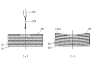
- FIG. 10 (a) shows the cross-sectional shape of an optical formed article 100 manufactured by the curing process of the optical forming method.
- a photofabricated object 100 as shown in FIG. 10A is a laminate of a large number of photocurable resin layers 101, and contains an uncured resin immediately after the curing step. Therefore, in the stereolithography method, after the stereolithography thing 100 manufactured at the hardening process is taken out from the inside of a container, hardening of the unhardened resin of the stereolithography thing 100 may progress over time.
- FIG. 10 (b) shows the cross-sectional shape of the photoformed object 100 in which the curing progressed with time after the completion of the curing step of the photo-forming method.
- the photofabricated product 100 that has completed the curing process causes a warp such that the final cured layer (final photocurable resin layer (N layer)) 101n side is recessed.
- the amount of light irradiation to the final cured layer 101 n and the photo-curable resin layer in the vicinity thereof is less than the amount of light irradiation to the other layers, and the final cured layer 101 n and the warp thereof Since a large amount of uncured resin is contained in the vicinity of the photocurable resin layer, the cause is that the uncured resin cures and shrinks over time. Then, the technique for preventing the curvature of such a photofabricated object 100 was developed. That is, according to the conventional warpage prevention technology of the photofabricated object 100, the irradiation energy amount of the light 103 irradiated when forming the final cured layer 101n is irradiated when forming the photocurable resin layer before that.
- the conventional warpage prevention technology for the optically modeled object 100 has a problem that it is difficult to adjust the amount of irradiation energy of the light 103 to be applied to the final cured layer 101 n and the warpage suppressing effect of the optically shaped object 100 is insufficient.
- this invention aims at provision of the optical shaping method which can suppress the curvature of an optical modeling thing.
- the stereolithography method according to the present invention is The liquid photocurable resin 2 in the container 1 is irradiated with light 5 to cure one layer of the photocurable resin layer 2a1 exposed to the light 5, and then the first photocurable resin is cured
- the liquid layer of the photocurable resin layer 2a2 in the second liquid layer is provided on the surface side of the layer 2a1 and the second liquid photocurable resin layer 2a2 in the liquid layer is irradiated with the light 5, and the light 5 is applied.
- the optical shaping method according to the present invention since the optical shaped object formed in the curing step is held in a state of being sandwiched by the warp suppressing members from both the front and back sides, warpage of the optical shaped object 6 can be suppressed.
- the object 6 can be manufactured with high accuracy.
- FIG. 2 (a) is a top view of the curvature suppression member used at a holding process
- FIG.2 (b) is FIG. 2 (a)
- FIG. 7 is a cross-sectional view of the warpage suppressing member shown by cutting along the line A1-A1 of FIG. It is a figure which shows the holding process of the optical shaping method which concerns on 2nd Embodiment of this invention,
- FIG. 2 (a) is a top view of the curvature suppression member used at a holding process
- FIG.2 (b) is FIG. 2 (a)
- FIG. 7 is a cross-sectional view of the warpage suppressing member shown by cutting along the line A1-A1 of FIG.
- FIG. 7 is a cross-sectional view of the warpage suppressing member shown by cutting along the line A1-A1 of FIG.
- FIG. 3 (a) is a top view of the curvature suppression member used at a holding process
- FIG.3 (b) is FIG. 3 (a)
- FIG. 6 is a cross-sectional view of the warpage suppressing member shown by cutting along line A2-A2 of FIG. It is a figure which shows the curvature suppression assistance member used at the holding
- FIG. 4 (a) is a top view of a curvature suppression assistance member
- FIG.4 (b) is curvature suppression.
- FIG. 4C is a side view of the auxiliary member
- FIG. 4C is a cross-sectional view of the warpage suppressing auxiliary member shown by cutting along line A3-A3 in FIG.
- FIG.10 (a) is a longitudinal cross-sectional view of the optical modeling thing which curvature has not produced
- FIG.10 (b) is a longitudinal cross-sectional view of the optical modeling thing which warpage has produced.
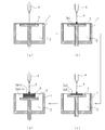
- FIG. 1 is a view showing a curing process of the optical shaping method according to the first embodiment of the present invention.
- a liquid photocurable resin 2 for example, an epoxy resin and an acrylate resin
- FIG. 1 (a) A liquid photocurable resin layer 2a1 for one layer is positioned on the table 3 (FIG. 1 (a)).
- the liquid photocurable resin layer 2a1 on the modeling table 3 is irradiated with the light 5 (for example, laser light) from the light irradiation means 4 and the modeling that the light 5 strikes
- the photocurable resin layer 2a1 for one layer on the table 3 is cured (FIG. 1 (b)).
- the optical shaping method according to the present embodiment descends the shaping table 3 and supplies the second liquid photocurable resin layer 2a2 onto the cured first photocurable resin layer 2a1.
- the second liquid photocurable resin layer 2a2 is irradiated with light 5 to cure the second photocurable resin layer 2a2 that the light 5 has hit (FIG. 1 (c)).
- the photofabrication method supplies a new liquid photocurable resin layer 2an on the cured photocurable resin layer 2a (n-1), and the liquid photocurable resin layer
- the operation of curing the liquid photocurable resin layer 2an by irradiating the light 2 with the light 5 is repeated, and the photocurable resin layer 2an of a plurality of layers (N layers) is stacked to form a three-dimensional shaped photofabricated object. It is designed to form 6 (Fig. 1 (d)).
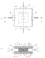
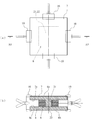
- FIG. 2 is a view showing the holding process of the optical forming method according to the embodiment of the present invention.
- 2 (a) is a plan view of the warpage suppressing member 7 used in the holding step
- FIG. 2 (b) is a warpage suppressing member 7 shown by being cut along line A1-A1 of FIG. 2 (a). , 8 in cross section.
- the optical figure 6 formed in the curing step is taken out from inside the container 1, and the surface of the optical figure 6 Warp suppressing members 7, 8 are respectively disposed on the 6a side (the upper surface side in FIG. 2B) and on the back surface 6b side (the lower surface side in FIG. 2B).
- the three-dimensional object 6 is sandwiched, and the three-dimensional object 6 is held by the holding means 10 such as a clip together with the warp suppressing members 7 and 8 on both the front and back sides.
- the warpage suppressing members 7, 8 may be made of, for example, a light transmitting resin material (polyacetal (POM), polyamide (PA), polyethylene terephthalate (PET), polycarbonate (PC), polymethyl methacrylate, etc.)
- POM polyacetal
- PA polyamide
- PET polyethylene terephthalate
- PC polycarbonate
- the surfaces 7 a and 8 a facing the photofabricated object 6 are shaped as if the surface shape of the photofabricated object 6 has been transferred.
- the warpage suppressing member 7 is in contact with the surface 6 a of the photofabricated object 6. Further, the warpage suppressing member 8 is in contact with the back surface 6 b of the photofabricated object 6.
- the warpage suppressing members 7 and 8 are formed in a rectangular shape larger in plan view than the rectangular optical shaped object 6, and formed so as to uniformly project outside the optical shaped object 6, and the optical shaped object The central portions of the four sides of the portion protruding outward beyond 6 are respectively held by the holding means 10.
- the warpage suppressing member 7 is formed with high accuracy by the 3D printer in such a shape that the surface 7 a facing the photofabricated object 6 has transferred the shape of the surface 6 a of the photofabricated portion 6.
- the rectangular shaped protrusion 12 fitted into the rectangular shape recess 11 at the center of the final cured layer (photocurable resin layer positioned at the top) of the photofabricated object 6 is the photofabricated object 6 Is formed on the surface 7a (lower surface) opposite to the bottom surface 11a of the recess 11 in the rectangular shape of the photofabricated object 6 (the photocurable resin layer 2a directly below the final cured layer 2an (n-1).
- the peripheral surface 7 a of the projection 12 is in contact with the surface 6 a of the final hardened layer 2 an of the photofabricated object 6.
- the holding means 10 has a size such that the spring force of a spring (not shown) can suppress the warp of the optically shaped article 6.
- the optical formed object 6 is held in a state of being sandwiched by the warp suppressing members 7 and 8 from both the front and back sides. Thereby, the warp of the optically shaped article 6 is suppressed.
- the optical shaped object 6 formed in the curing step is held in a state of being held between the warpage suppressing members 7 and 8, thereby causing the optical shaped object 6 to warp.
- the photofabricated object 6 can be manufactured with high accuracy.
- FIG. 3 is a view showing the holding process of the optical shaping method according to the second embodiment of the present invention.
- the optical shaping method which concerns on this embodiment is as common as the curing process of the optical shaping method which concerns on 1st Embodiment the hardening process, it abbreviate
- . 3 (a) is a plan view of the warpage suppressing member 7 used in the holding step
- FIG. 3 (b) is a sectional view taken along line A2-A2 of FIG. 3 (a). It is sectional drawing of the curvature suppression members 7 and 8.
- FIG. 3 (a) is a plan view of the warpage suppressing member 7 used in the holding step
- FIG. 3 (b) is a sectional view taken along line A2-A2 of FIG. 3 (a). It is sectional drawing of the curvature suppression members 7 and 8.
- the holding step of the optical forming method according to the present embodiment shown in FIG. 3 is the surface of the optical form 6 among the warpage suppressing members 7 and 8 disposed on the front and back sides of the optical form 6 formed in the curing step.
- the warpage suppressing auxiliary member 13 for restraining the warp of the photofabricated object 6 together with the warpage suppressing member 7 is disposed doing.
- positioned at the surface 6a side of the optical molded article 6 is made into the 1st curvature suppression member 7, and the curvature suppression member 8 arrange
- the warpage suppressing member 8 is used.
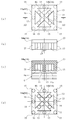
- FIG. 4 is a view showing the warpage suppressing auxiliary member 13 used in the holding step of the optical forming method.
- 4 (a) is a plan view of the warpage suppressing auxiliary member 13
- FIG. 4 (b) is a side view of the warpage suppressing auxiliary member 13
- FIG. 4 (c) is an A3- of FIG. 4 (a). It is sectional drawing of the curvature suppression auxiliary member 13 cut
- the warpage suppressing auxiliary member 13 has a rectangular shape which is the same as that of the photofabricated object 6 in the outer edge shape in plan view.
- the warpage suppressing auxiliary member 13 has a beam portion 14 in contact with the first warpage suppressing member 7 and a plurality of leg portions 15 extending from the beam portion 14 and in contact with the photofabricated object 6.
- the beam portion 14 integrally includes a rectangular frame portion 14a located along the outer edge of the photofabricated object 6, and a pair of brace beam portions 14b connecting opposing corners of the frame portion 14a. .
- the curvature suppression assistance member 13 is the leg part 15 which contact
- a plurality of are formed.
- the leg portion 15 is formed in a round bar shape and is formed to be located at each corner of the frame portion 14a, and is formed at an intermediate position between adjacent corners of the frame portion 14a.
- leg portion 15 is formed at a position where the pair of bracing beam portions 14b and 14b cross in a cross shape (the central position of the warpage suppressing auxiliary member 13 in plan view), and the rectangular shape of the photofabricated object 6
- the pair of bracing beam portions 14 b and 14 b are formed so as to be located in the vicinity of the outer edge of the recess 11.
- leg part 15 located in the central part at the time of plane view abuts on the center of bottom 11a of dent 11 of optical modeling part 6, and a plurality of other leg parts 15 are optical fabrication things in warpage control auxiliary member 13 It comes in contact with the surface 6a of 6 (the upper surface in FIG. 3 (b)).
- a triangular window (space) 16 is formed between the frame portion 14a of the beam portion 14 and the pair of bracing beam portions 14b and 14b, and the tip of the leg portion 15 is formed by optical shaping In the state of being in contact with the surface 6 a side (upper surface side) of the object 6, a gap 17 is generated between the beam portion 14 and the optically modeled object 6. Note that such a warpage suppressing auxiliary member 13 is formed with high accuracy by the 3D printer so that the tip end of the leg portion 15 accurately abuts on the photofabricated object 6.
- the optically shaped object 6 formed in the curing step abuts the second warp suppressing member 8 with no gap on the back surface 6b side (lower surface side), and the surface 6a
- the side (upper surface side) is in contact with the plurality of leg portions 15 of the warpage suppressing auxiliary member 13 without a gap.
- the beam portion 14 of the warpage suppressing auxiliary member 13 is in contact with the first warpage suppressing member 7.
- the optically shaped object 6 formed in the curing step is held by the first warpage suppressing member 7 and the second warpage suppressing member 8 by the holding means 10 such as a clip so that the holding means such as the clip is held.
- the holding force of 10 acts via the first warpage suppressing member 7 and the warpage suppressing auxiliary member 13, and the pinching force of the holding means 10 such as a clip works via the second warpage suppressing member 8, and holds the clip etc.
- the holding force of the means 10 suppresses warpage.
- the optical object 6 formed in the curing step is held between the first warpage suppressing member 7 and the warpage suppressing auxiliary member 13 and the second warpage suppressing member 8. Since the optically shaped object 6 is held in a state in which the warp of the optically shaped object 6 is suppressed, the optically shaped object 6 can be manufactured with high accuracy.
- the optical forming method when manufacturing a plurality of types of optical shapes 6 having different surface shapes, only the warpage suppressing auxiliary member 13 is formed by the 3D printer according to the shape of the optical shapes 6
- the first warpage suppressing member 7 and the second warpage suppressing member 8 can be commonly used in the manufacture of a plurality of types of photofabricated objects 6, and the entire first warpage suppressing member 7 can be photoformed Compared with the case where it forms according to the shape of the thing 6, the manufacturing cost of the optical molded article 6 can be reduced.
- the optical shaping method which concerns on this embodiment illustrated the structure which arrange
- the warpage suppressing auxiliary member 13 may be disposed between the optical model 6 and the second warpage suppressing member 8 as well.
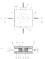
- FIG. 5 is a view showing the holding process of the optical shaping method according to the third embodiment of the present invention.
- the optical shaping method which concerns on this embodiment is as common as the curing process of the optical shaping method which concerns on 1st Embodiment the hardening process, it abbreviate
- . 5 (a) is a plan view of the warpage suppressing member 7 used in the holding step
- FIG. 5 (b) is a sectional view taken along line A4-A4 of FIG. 5 (a). It is sectional drawing of the curvature suppression members 7 and 8.
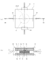
- the photofabricated object 6 is formed in a donut shape having a circular outer edge and having a through hole 18 at the center.
- the warpage suppressing member 7 disposed on the surface 6 a side of the photofabricated object 6 is referred to as a first warpage suppressing member 7, and the warping suppressing member 8 disposed on the back surface 6 b side of the photofabricated object 6 is referred to as a second warpage suppressing member 8 .
- the first warpage suppressing member 7 has a rectangular shape in a plan view, and is formed to have a size projecting outward of the optical three-dimensional object 6, and the lower surface (lower surface)
- the lower surface 7 a is in contact with the surface 6 a of the optically modeled object 6 in a state where the round rod-like protrusion 20 formed at the center of 7 a is inserted into the through hole 18 of the optically modeled object 6.
- the round rod-like protrusion 20 of the first warpage suppressing member 7 has a length at which the tip (lower end) abuts on the second warpage suppressing member 8 or a slight gap is generated between the tip and the second warpage suppressing member 8 It is formed.
- the second warpage suppressing member 8 has a shape in which the round rod-like protrusion 20 of the first warpage suppressing member 7 is removed.
- the doughnut-shaped optical object 6 formed in the curing step is sandwiched between the first warpage suppressing member 7 and the second warpage suppressing member 8 to suppress the first warpage.
- the sandwiching force of the sandwiching means 10 to the member 7, the optical figure 6, and the second warpage suppressing member 8, the optical figure 6 can be held in a state in which the warpage of the optical figure 6 is suppressed.
- the photofabricated object 6 can be manufactured with high accuracy.
- FIG. 6 is a view showing the holding process of the optical shaping method according to the fourth embodiment of the present invention.
- the optical shaping method which concerns on this embodiment is as common as the curing process of the optical shaping method which concerns on 1st Embodiment the hardening process, it abbreviate
- 6 (a) is a plan view of the warpage suppressing member 7 used in the holding step, and FIG. 6 (b) is cut along line A5-A5 in FIG. 6 (a). It is sectional drawing of the curvature suppression members 7 and 8.
- the optical three-dimensional object 6 is formed in a frame shape having a rectangular outer edge shape and a rectangular through hole 21 at the central portion.
- the warpage suppressing member 7 disposed on the surface 6 a side of the photofabricated object 6 is referred to as a first warpage suppressing member 7, and the warping suppressing member 8 disposed on the back surface 6 b side of the photofabricated object 6 is referred to as a second warpage suppressing member 8 .
- the first warpage suppressing member 7 has a rectangular shape in a plan view, and is formed in a size projecting outward of the optical three-dimensional object 6 and formed at the center of the lower surface 7 a
- the lower surface 7 a is in contact with the surface 6 a of the photoformed object 6 in a state where the square rod-like protrusion 22 is inserted into the rectangular through hole 21 of the photoformed object 6.
- the square rod-like protrusion 22 of the first warpage suppressing member 7 has a length at which the tip (lower end) abuts on the second warpage suppressing member 8 or a slight gap is generated between the tip and the second warpage suppressing member 8 It is formed.
- the second warpage suppressing member 8 has a shape in which the square rod-like projections 22 of the first warpage suppressing member 7 are removed.
- the first warpage suppressing member 7 and the second warpage suppressing member 8 sandwich the frame-shaped photoformed object 6 formed in the curing step, thereby suppressing the first warpage
- the optical figure 6 can be held in a state in which the warpage of the optical figure 6 is suppressed.
- the photofabricated object 6 can be manufactured with high accuracy.
- FIG. 7 is a view showing the holding process of the optical shaping method according to the fifth embodiment of the present invention.
- the optical shaping method which concerns on this embodiment is as common as the curing process of the optical shaping method which concerns on 1st Embodiment the hardening process, it abbreviate
- . 7 (a) is a plan view of the warpage suppressing member 7 used in the holding step
- FIG. 7 (b) is a sectional view taken along line A6-A6 of FIG. 7 (a). It is sectional drawing of the curvature suppression members 7 and 8.
- the photofabricated object 6 has a circular outer edge, and a spherical projection 23 formed by cutting a part of a sphere is formed on the surface 6 a side of the central portion.
- the warpage suppressing member 7 disposed on the surface 6 a side of the photofabricated object 6 is referred to as a first warpage suppressing member 7, and the warping suppressing member 8 disposed on the back surface 6 b side of the photofabricated object 6 is referred to as a second warpage suppressing member 8 .
- the first warpage suppressing member 7 has a rectangular shape in a plan view, is formed to have a size projecting outward of the optical three-dimensional object 6, and is formed at the center of the lower surface 7 a
- the lower surface 7 a is in contact with the surface 6 a of the photofabricated object 6 in a state where the spherical recess 24 is engaged with the spherical projection 23 of the photofabricated object 6.
- the spherical recess 24 of the first warpage suppressing member 7 has a shape as if the spherical projection 23 of the photofabricated object 6 is transferred, and abuts on the spherical projection 23 of the photofabricated object 6 or light It is formed in the magnitude
- the second warpage suppressing member 8 has a shape in which the spherical recess 24 of the first warpage suppressing member 7 is omitted.
- the first warp suppressing member 7 sandwiches the photoformed object 6 formed in the curing step between the first warpage suppressing member 7 and the second warpage suppressing member 8;
- the sandwiching force of the sandwiching means 10 to the optically shaped object 6 and the second warp suppressing member 8
- the optically shaped object 6 can be held in a state in which the warp of the optically shaped object 6 is suppressed. 6 can be manufactured with high precision.
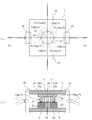
- FIG. 8 is a view showing the holding process of the optical shaping method according to the sixth embodiment of the present invention.
- the optical shaping method which concerns on this embodiment is as common as the curing process of the optical shaping method which concerns on 1st Embodiment the hardening process, it abbreviate
- . 8 (a) is a plan view of the warpage suppressing member 7 used in the holding step, and FIG. 8 (b) is cut along the A7-A7 line of FIG. 8 (a).
- FIG. 6 is a cross-sectional view of the warpage suppressing member 7, the warpage suppressing auxiliary member 13, the photofabricated object 6, and the warpage suppressing member 8.
- the holding step of the optical forming method according to the present embodiment shown in FIG. 8 is the warpage suppressing members 7, 8 disposed on both the front and back sides (6a, 6b) of the doughnut-shaped optical formed object 6 formed in the curing step.
- the warpage suppressing member 7 and the warpage suppressing member 7 are disposed between the warpage suppressing member 7 disposed on the surface 6 a side of the optical molding thing 6 (the upper side in FIG.
- the warpage suppressing auxiliary member 13 for suppressing is disposed.
- positioned at the surface 6a side of the optical molded article 6 is made into the 1st curvature suppression member 7, and the curvature suppression member 8 arrange
- the warpage suppressing member 8 is used.
- four projections 25 are formed at equal intervals along the circumferential direction on the surface 6a side (on a circle 27 concentric with the center 26 of the through hole 18).
- the warpage suppressing auxiliary member 13 has a circular shape whose outer edge shape in plan view is the same as that of the photofabricated object 6.
- the warpage suppressing auxiliary member 13 has a disk-like beam portion 14 in contact with the first warpage suppressing member 7 and a plurality of round bar-like leg portions 15 extending from the beam portion 14 and in contact with the photofabricated object 6. And.
- the leg portion 15 of the warpage suppressing auxiliary member 13 is along the circumferential direction of the surface of the beam portion 14 facing the photofabricated object 6 (on a circle 27 concentric with the center 26 of the through hole 18 of the photofabricated object 6) Eight locations are formed at equal intervals.
- the eight legs 15 are alternately formed by first legs 15a in contact with the protrusions 25 of the optical three-dimensional object 6 and second legs 15b in contact with the surface 6a between the protrusions 25 of the optical three-dimensional object 6. Is located in The warpage suppressing auxiliary member 13 is formed with high accuracy by the 3D printer so that the tip end of the leg portion 15 accurately abuts on the photofabricated object 6. Further, the shape and the number of the leg portions 15 of the warpage suppressing auxiliary member 13 are not limited to the present embodiment, and the optimum shape and the number are determined according to the shape, the number, and the like of the protrusions 25 of the photofabricated object 6. Further, a gap 17 is formed between the adjacent legs 15 and 15.
- the optically shaped object 6 formed in the curing step abuts the second warp suppressing member 8 with no gap on the back surface 6b side (lower surface side), and the surface 6a
- the side (upper surface side) is in contact with the plurality of leg portions 15 of the warpage suppressing auxiliary member 13 without a gap.
- the beam portion 14 of the warpage suppressing auxiliary member 13 is in contact with the first warpage suppressing member 7.
- the optically shaped object 6 formed in the curing step is held by the first warpage suppressing member 7 and the second warpage suppressing member 8 by the holding means 10 such as a clip so that the holding means such as the clip is held.
- the holding force of 10 acts via the first warpage suppressing member 7 and the warpage suppressing auxiliary member 13, and the pinching force of the holding means 10 such as a clip works via the second warpage suppressing member 8, and holds the clip etc.
- the holding force of the means 10 suppresses warpage.
- the optical object 6 formed in the curing step is held between the first warpage suppressing member 7 and the warpage suppressing auxiliary member 13 and the second warpage suppressing member 8. Since the optically shaped object 6 is held in a state in which the warp of the optically shaped object 6 is suppressed, the optically shaped object 6 can be manufactured with high accuracy.
- the optical forming method when manufacturing a plurality of types of optical shapes 6 having different surface shapes, only the warpage suppressing auxiliary member 13 is formed by the 3D printer according to the shape of the optical shapes 6
- the first warpage suppressing member 7 and the second warpage suppressing member 8 can be commonly used in the manufacture of a plurality of types of photofabricated objects 6, and the entire first warpage suppressing member 7 can be photoformed Compared with the case where it forms according to the shape of the thing 6, the manufacturing cost of the optical molded article 6 can be reduced.
- FIG. 9 is a view showing the holding process of the optical forming method according to the seventh embodiment of the present invention, and is a view showing a modified example of the holding process of the optical forming method according to the sixth embodiment.
- the optical shaping method which concerns on this embodiment is as common as the curing process of the optical shaping method which concerns on 1st Embodiment the hardening process, it abbreviate
- FIG. 9 (a) is a plan view of the warpage suppressing member 7 used in the holding step
- FIG. 9 (b) is cut along line A8-A8 in FIG. 9 (a).
- FIG. 7 is a cross-sectional view of the warpage suppressing member 7, the warpage suppressing auxiliary member 13, the photofabricated object 6, the warpage suppressing auxiliary member 13, and the warpage suppressing member 8.
- the stereolithography method when the same number of projections 25 are formed on both the front and back sides (6a, 6b) of the stereolithography object 6, between the stereolithography object 6 and the first warpage suppressing member 7
- the first warpage suppressing auxiliary member 13 may be disposed, and the second warpage suppressing auxiliary member 13 may be disposed between the photofabricated object 6 and the second warpage suppressing member 8.
- the same effect as the optical forming method according to the sixth embodiment can be obtained.
Landscapes
- Engineering & Computer Science (AREA)
- Chemical & Material Sciences (AREA)
- Materials Engineering (AREA)
- Manufacturing & Machinery (AREA)
- Physics & Mathematics (AREA)
- Mechanical Engineering (AREA)
- Optics & Photonics (AREA)
- Robotics (AREA)
Abstract
光造形物の反りを防止できる光造形法を提供する。 光造形法は、硬化工程と保持工程とを有している。硬化工程は、容器内の液状の光硬化性樹脂に光を照射し、光が当たった1層分の光硬化性樹脂層を硬化させ、次に硬化した1層目の光硬化性樹脂層の表面側に重ねて2層目の液状の光硬化性樹脂層を供給し、その2層目の液状の光硬化性樹脂層に光を照射し、光が当たった2層目の光硬化性樹脂層を硬化させる、作業をN層まで繰り返し行って、3次元形状の光造形物を形作る。保持工程は、光造形物(6)を容器内から取り出し、光造形物(6)の表裏両側にそれぞれ配置した反り抑制部材(7,8)で光造形物(6)を表裏両側から挟み込んだ状態で保持する。
Description
この発明は、光硬化性樹脂に光を照射して光造形物を製造する光造形法に関するものである。
従来から知られている光造形法は、硬化工程において、容器内の液状の光硬化性樹脂に光(例えば、レーザー光)を照射し、光が当たった造形テーブル上の1層分の光硬化性樹脂を硬化させ、次に造形テーブルを移動させて硬化した1層目の光硬化性樹脂の上に2層目の液状の光硬化性樹脂を供給し、その2層目の液状の光硬化性樹脂に光を照射し、光が当たった2層目の光硬化性樹脂を硬化させ、このような作業をN層まで繰り返し行って、所望の3次元形状の光造形物を形作るようになっている。
図10(a)は、光造形法の硬化工程によって製造される光造形物100の断面形状を示すものである。この図10(a)に示すような光造形物100は、光硬化性樹脂層101が多数積層されたものであり、硬化工程の直後において、未硬化樹脂を含有している。そのため、光造形法は、硬化工程で製造された光造形物100を容器内から取り出した後、その光造形物100の未硬化樹脂の硬化が経時で進行することがある。
図10(b)は、光造形法の硬化工程を終了した後、硬化が経時で進行した光造形物100の断面形状を示すものである。この図10(b)に示すように、硬化工程を終了した光造形物100は、最終硬化層(最終の光硬化性樹脂層(N層))101n側が凹むような反りを生じる。このような光造形物100の反りは、最終硬化層101n及びその近傍の光硬化性樹脂層への光照射量が他層への光照射量よりも不足しており、最終硬化層101n及びその近傍の光硬化性樹脂層に多くの未硬化樹脂が含まれているため、未硬化樹脂が経時で硬化して収縮することが原因になっている。そこで、このような光造形物100の反りを防止するための技術が開発された。すなわち、従来の光造形物100の反り防止技術は、最終硬化層101nを形成する際に照射される光103の照射エネルギー量を、それ以前の光硬化性樹脂層を形成する際に照射される光103の照射エネルギーよりも大きくして、最終硬化層101n及びその近傍の光硬化性樹脂層の未硬化樹脂の量とそれ以前の光硬化性樹脂層の未硬化樹脂の量を同程度にし、各光硬化性樹脂層の収縮を均等化して、光造形物100の反りを防止しようとする技術である(特許文献1参照)。
しかしながら、従来の光造形物100の反り防止技術は、最終硬化層101nに照射する光103の照射エネルギーの量の調整が難しく、光造形物100の反り抑制効果が不十分であるという問題があった。
そこで、本発明は、光造形物の反りを抑制できる光造形法の提供を目的とする。
本発明に係る光造形法は、
容器1内の液状の光硬化性樹脂2に光5を照射し、光5が当たった1層分の光硬化性樹脂層2a1を硬化させ、次に硬化した1層目の前記光硬化性樹脂層2a1の表面側に重ねて2層目の液状の前記光硬化性樹脂層2a2を供給し、その2層目の液状の光硬化性樹脂層2a2に光5を照射し、光5が当たった2層目の光硬化性樹脂層2a2を硬化させる、作業をN層まで繰り返し行って、3次元形状の光造形物6を形作る硬化工程と、
前記光造形物6を前記容器1内から取り出し、前記光造形物6の表裏両側にそれぞれ配置した反り抑制部材7,8で前記光造形物6を表裏両側から挟み込んだ状態で保持する保持工程と、を有している。
容器1内の液状の光硬化性樹脂2に光5を照射し、光5が当たった1層分の光硬化性樹脂層2a1を硬化させ、次に硬化した1層目の前記光硬化性樹脂層2a1の表面側に重ねて2層目の液状の前記光硬化性樹脂層2a2を供給し、その2層目の液状の光硬化性樹脂層2a2に光5を照射し、光5が当たった2層目の光硬化性樹脂層2a2を硬化させる、作業をN層まで繰り返し行って、3次元形状の光造形物6を形作る硬化工程と、
前記光造形物6を前記容器1内から取り出し、前記光造形物6の表裏両側にそれぞれ配置した反り抑制部材7,8で前記光造形物6を表裏両側から挟み込んだ状態で保持する保持工程と、を有している。
本発明に係る光造形法によれば、硬化工程で形作られた光造形物を表裏両面から反り抑制部材によって挟み込んだ状態で保持することにより、光造形物6の反りを抑制できるため、光造形物6を高精度に製造できる。
以下、本発明の実施形態を図面に基づき詳述する。
[第1実施形態]
図1は、本発明の第1実施形態に係る光造形法の硬化工程を示す図である。この図1に示すように、本実施形態に係る光造形法は、容器1内に液状の光硬化性樹脂2(例えば、エポキシ系樹脂、アクリレート系樹脂)を入れ、容器1内を昇降する造形テーブル3上に1層分の液状の光硬化性樹脂層2a1を位置させる(図1(a))。
図1は、本発明の第1実施形態に係る光造形法の硬化工程を示す図である。この図1に示すように、本実施形態に係る光造形法は、容器1内に液状の光硬化性樹脂2(例えば、エポキシ系樹脂、アクリレート系樹脂)を入れ、容器1内を昇降する造形テーブル3上に1層分の液状の光硬化性樹脂層2a1を位置させる(図1(a))。
次に、本実施形態に係る光造形法は、造形テーブル3上の液状の光硬化性樹脂層2a1に光照射手段4から光5(例えば、レーザー光)を照射し、光5が当たった造形テーブル3上の1層分の光硬化性樹脂層2a1を硬化させる(図1(b))。
次に、本実施形態に係る光造形法は、造形テーブル3を降下させ、硬化した1層目の光硬化性樹脂層2a1の上に2層目の液状の光硬化性樹脂層2a2を供給し、その2層目の液状の光硬化性樹脂層2a2に光5を照射し、光5が当たった2層目の光硬化性樹脂層2a2を硬化させる(図1(c))。
そして、本実施形態に係る光造形法は、硬化した光硬化性樹脂層2a(n-1)の上に新たな液状の光硬化性樹脂層2anを供給し、その液状の光硬化性樹脂層2anに光5を照射して、液状の光硬化性樹脂層2anを硬化させるという作業を繰り返し行い、複数層(N層)の光硬化性樹脂層2anを積み重ねて、3次元形状の光造形物6を形作るようになっている(図1(d))。
図2は、本発明の実施形態に係る光造形法の保持工程を示す図である。なお、図2(a)は保持工程で使用する反り抑制部材7の平面図であり、図2(b)は図2(a)のA1-A1線に沿って切断して示す反り抑制部材7,8の断面図である。
この図2に示すように、本実施形態に係る光造形法の保持工程は、第1段階として、硬化工程で形作られた光造形物6を容器1内から取り出し、その光造形物6の表面6a側(図2(b)の上面側)と裏面6b側(図2(b)の下面側)とに反り抑制部材7,8をそれぞれ配置し、これら反り抑制部材7,8の間に光造形物6を挟み込み、光造形物6を表裏両側の反り抑制部材7,8と共にクリップ等の挟持手段10で挟持する。
反り抑制部材7,8は、例えば、光透過性の樹脂材料(ポリアセタール(POM)、ポリアミド(PA)、ポリエチレンテレフタレート(PET)、ポリカーボネート(PC)、ポリメタクリル酸メチル等)で形成してもよく、光造形物6に対向する面7a,8aが光造形物6の表面形状を転写したような形状になっている。そして、反り抑制部材7は、光造形物6の表面6aに当接するようになっている。また、反り抑制部材8は、光造形物6の裏面6bに当接するようになっている。また、反り抑制部材7,8は、平面視した形状が矩形形状の光造形物6よりも大きな矩形形状に形成され、光造形物6の外側に均等に張り出すように形成され、光造形物6よりも外側に張り出した部分の4辺の中央部がそれぞれ挟持手段10で挟持されるようになっている。なお、この反り抑制部材7は、その光造形物6に対向する面7aが光造形部6の表面6aの形状を転写したような形状に3Dプリンタによって高精度に形成される。すなわち、反り抑制部材7は、光造形物6の最終硬化層(最上部に位置する光硬化性樹脂層)2anの中央の矩形形状の凹み11に嵌り込む矩形形状の突起12が光造形物6に対向する面7a(下面)に形成され、この突起12の先端面が光造形物6の矩形形状の凹み11の底面11a(最終硬化層2anの直下の光硬化性樹脂層2a(n-1)の上面)に当接し、突起12の周囲の面7aが光造形物6の最終硬化層2anの表面6aに当接している。また、挟持手段10は、図示しないばねのばね力が光造形物6の反りを抑制できる大きさになっている。
次に、光造形法の保持工程は、光造形物6を表裏両側から反り抑制部材7,8で挟持した状態で保持する。これにより、光造形物6は、反りが抑制される。
以上のように、本実施形態に係る光造形法によれば、硬化工程で形作られた光造形物6を反り抑制部材7,8で挟持した状態で保持することにより、光造形物6の反りを抑制できるため、光造形物6を高精度に製造できる。
[第2実施形態]
図3は、本発明の第2実施形態に係る光造形法の保持工程を示す図である。なお、本実施形態に係る光造形法は、硬化工程が第1実施形態に係る光造形法の硬化工程と共通するため、第1実施形態に係る光造形法の説明と重複する説明を省略する。また、図3において、図3(a)は保持工程で使用する反り抑制部材7の平面図であり、図3(b)は図3(a)のA2-A2線に沿って切断して示す反り抑制部材7,8の断面図である。
図3は、本発明の第2実施形態に係る光造形法の保持工程を示す図である。なお、本実施形態に係る光造形法は、硬化工程が第1実施形態に係る光造形法の硬化工程と共通するため、第1実施形態に係る光造形法の説明と重複する説明を省略する。また、図3において、図3(a)は保持工程で使用する反り抑制部材7の平面図であり、図3(b)は図3(a)のA2-A2線に沿って切断して示す反り抑制部材7,8の断面図である。
図3に示す本実施形態に係る光造形法の保持工程は、硬化工程で形作られた光造形物6の表裏両側に配置される反り抑制部材7,8のうちで、光造形物6の表面6a側(図3(b)の上側)に配置される反り抑制部材7と光造形物6との間に、光造形物6の反りを反り抑制部材7と共に抑制する反り抑制補助部材13を配置している。なお、説明の便宜上、光造形物6の表面6a側に配置される反り抑制部材7を第1反り抑制部材7とし、光造形物6の裏面6b側に配置される反り抑制部材8を第2反り抑制部材8とする。
図4は、光造形法の保持工程で使用される反り抑制補助部材13を示す図である。なお、図4(a)は反り抑制補助部材13の平面図であり、図4(b)は反り抑制補助部材13の側面図であり、図4(c)は図4(a)のA3-A3線に沿って切断して示す反り抑制補助部材13の断面図であり、図4(d)は反り抑制補助部材13の裏面図である。
図3及び図4に示すように、反り抑制補助部材13は、平面視した外縁形状が光造形物6と同一の矩形形状である。そして、この反り抑制補助部材13は、第1反り抑制部材7に当接する梁部14と、この梁部14から延びて光造形物6に当接する複数の脚部15と、を有している。梁部14は、光造形物6の外縁に沿って位置する矩形形状の枠部分14aと、枠部分14aの対向するコーナーを接続する一対の筋交い状梁部分14bと、を一体に有している。そして、反り抑制補助部材13は、梁部14の光造形物6に対向する面側(図4(b)、図4(c)の下面側)に、光造形物6に当接する脚部15が複数形成されている。脚部15は、丸棒状に形成され、枠部分14aの各コーナーに位置するように形成されると共に、枠部分14aの隣り合うコーナーの中間位置に形成されている。また、脚部15は、一対の筋交い状梁部分14b,14bが十字状に交差する位置(平面視した反り抑制補助部材13の中心位置)に形成されると共に、光造形物6の矩形状の凹み11の外縁近傍に位置するように一対の筋交い状梁部分14b,14bに形成されている。そして、反り抑制補助部材13は、平面視した場合の中心部分に位置する脚部15が光造形部6の凹み11の底面11aの中央に当接し、他の複数の脚部15が光造形物6の表面6a(図3(b)の上面)に当接するようになっている。
また、反り抑制補助部材13は、梁部14の枠部分14aと一対の筋交い状梁部分14b,14bとの間に三角状の窓(スペース)16が形成され、脚部15の先端が光造形物6の表面6a側(上面側)に当接した状態において、梁部14と光造形物6との間に隙間17が生じるようになっている。なお、このような反り抑制補助部材13は、脚部15の先端が正確に光造形物6に当接するように、3Dプリンタによって高精度に形成される。
このような本実施形態に係る光造形法の保持工程において、硬化工程で形作られた光造形物6は、裏面6b側(下面側)が第2反り抑制部材8に隙間無く当接し、表面6a側(上面側)が反り抑制補助部材13の複数の脚部15に隙間無く当接している。そして、反り抑制補助部材13は、梁部14が第1反り抑制部材7に当接している。このような状態において、硬化工程において形作られた光造形物6は、第1反り抑制部材7と第2反り抑制部材8がクリップ等の挟持手段10によって挟持されることにより、クリップ等の挟持手段10の挟持力が第1反り抑制部材7及び反り抑制補助部材13を介して作用すると共に、クリップ等の挟持手段10の挟持力が第2反り抑制部材8を介して作用し、クリップ等の挟持手段10の挟持力によって反りが抑制される。
以上のように、本実施形態に係る光造形法によれば、硬化工程で形作られた光造形物6を第1反り抑制部材7及び反り抑制補助部材13と第2反り抑制部材8で挟持し、光造形物6の反りを抑制した状態で光造形物6を保持するようになっているため、光造形物6を高精度に製造できる。
また、本実施形態に係る光造形法によれば、表面形状が異なる複数種の光造形物6を製造する場合、反り抑制補助部材13のみを光造形物6の形状に応じて3Dプリンタで形成することにより、第1反り抑制部材7及び第2反り抑制部材8を複数種の光造形物6の製造に共通して使用することが可能であり、第1反り抑制部材7の全体を光造形物6の形状に応じて形成する場合と比較し、光造形物6の製造コストを低減することができる。
なお、本実施形態に係る光造形法は、光造形物6と第1反り抑制部材7との間にのみ反り抑制補助部材13を配置する構成を例示したが、光造形物6の裏面6b側(下面側)にも凹凸部が形成される場合、光造形物6と第2反り抑制部材8との間にも反り抑制補助部材13を配置してもよい。
[第3実施形態]
図5は、本発明の第3実施形態に係る光造形法の保持工程を示す図である。なお、本実施形態に係る光造形法は、硬化工程が第1実施形態に係る光造形法の硬化工程と共通するため、第1実施形態に係る光造形法の説明と重複する説明を省略する。また、図5において、図5(a)は保持工程で使用する反り抑制部材7の平面図であり、図5(b)は図5(a)のA4-A4線に沿って切断して示す反り抑制部材7,8の断面図である。また、本実施形態において、光造形物6は、外縁形状が円形で、且つ、中央部に貫通孔18を有するドーナツ形状に形成されている。
図5は、本発明の第3実施形態に係る光造形法の保持工程を示す図である。なお、本実施形態に係る光造形法は、硬化工程が第1実施形態に係る光造形法の硬化工程と共通するため、第1実施形態に係る光造形法の説明と重複する説明を省略する。また、図5において、図5(a)は保持工程で使用する反り抑制部材7の平面図であり、図5(b)は図5(a)のA4-A4線に沿って切断して示す反り抑制部材7,8の断面図である。また、本実施形態において、光造形物6は、外縁形状が円形で、且つ、中央部に貫通孔18を有するドーナツ形状に形成されている。
図5に示す本実施形態に係る光造形法の保持工程において、硬化工程で形作られた光造形物6の表裏両面(6a,6b)側に配置される反り抑制部材7,8のうちで、光造形物6の表面6a側に配置される反り抑制部材7を第1反り抑制部材7とし、光造形物6の裏面6b側に配置される反り抑制部材8を第2反り抑制部材8とする。
図5に示すように、第1反り抑制部材7は、平面視した形状が矩形形状であり、光造形物6の外方に張り出すような大きさに形成され、下側の面(下面)7aの中央に形成された丸棒状突起20が光造形物6の貫通孔18に挿入された状態で、下面7aが光造形物6の表面6aに当接するようになっている。第1反り抑制部材7の丸棒状突起20は、先端(下端)が第2反り抑制部材8に当接するか、又は先端と第2反り抑制部材8との間に僅かな隙間が生じる長さに形成されている。そして、第2反り抑制部材8は、第1反り抑制部材7の丸棒状突起20を取り除いた形状になっている。
本実施形態に係る光造形法の保持工程によれば、硬化工程で形作られたドーナツ形状の光造形物6を第1反り抑制部材7と第2反り抑制部材8とで挟み、第1反り抑制部材7、光造形物6、及び第2反り抑制部材8に挟持手段10の挟持力を加えることにより、光造形物6の反りを抑制した状態で光造形物6を保持することができるため、光造形物6を高精度に製造できる。
[第4実施形態]
図6は、本発明の第4実施形態に係る光造形法の保持工程を示す図である。なお、本実施形態に係る光造形法は、硬化工程が第1実施形態に係る光造形法の硬化工程と共通するため、第1実施形態に係る光造形法の説明と重複する説明を省略する。また、図6において、図6(a)は保持工程で使用する反り抑制部材7の平面図であり、図6(b)は図6(a)のA5-A5線に沿って切断して示す反り抑制部材7,8の断面図である。また、本実施形態において、光造形物6は、外縁形状が矩形形状で、且つ、中央部に矩形形状の貫通孔21を有する額縁形状に形成されている。
図6は、本発明の第4実施形態に係る光造形法の保持工程を示す図である。なお、本実施形態に係る光造形法は、硬化工程が第1実施形態に係る光造形法の硬化工程と共通するため、第1実施形態に係る光造形法の説明と重複する説明を省略する。また、図6において、図6(a)は保持工程で使用する反り抑制部材7の平面図であり、図6(b)は図6(a)のA5-A5線に沿って切断して示す反り抑制部材7,8の断面図である。また、本実施形態において、光造形物6は、外縁形状が矩形形状で、且つ、中央部に矩形形状の貫通孔21を有する額縁形状に形成されている。
図6に示す本実施形態に係る光造形法の保持工程において、硬化工程で形作られた光造形物6の表裏両面(6a,6b)側に配置される反り抑制部材7,8のうちで、光造形物6の表面6a側に配置される反り抑制部材7を第1反り抑制部材7とし、光造形物6の裏面6b側に配置される反り抑制部材8を第2反り抑制部材8とする。
図6に示すように、第1反り抑制部材7は、平面視した形状が矩形形状であり、光造形物6の外方に張り出すような大きさに形成され、下面7aの中央に形成された角棒状突起22が光造形物6の矩形形状の貫通孔21に挿入された状態で、下面7aが光造形物6の表面6aに当接するようになっている。第1反り抑制部材7の角棒状突起22は、先端(下端)が第2反り抑制部材8に当接するか、又は先端と第2反り抑制部材8との間に僅かな隙間が生じる長さに形成されている。そして、第2反り抑制部材8は、第1反り抑制部材7の角棒状突起22を取り除いた形状になっている。
本実施形態に係る光造形法の保持工程によれば、硬化工程で形作られた額縁形状の光造形物6を第1反り抑制部材7と第2反り抑制部材8とで挟み、第1反り抑制部材7、光造形物6、及び第2反り抑制部材8に挟持手段10の挟持力を加えることにより、光造形物6の反りを抑制した状態で光造形物6を保持することができるため、光造形物6を高精度に製造できる。
[第5実施形態]
図7は、本発明の第5実施形態に係る光造形法の保持工程を示す図である。なお、本実施形態に係る光造形法は、硬化工程が第1実施形態に係る光造形法の硬化工程と共通するため、第1実施形態に係る光造形法の説明と重複する説明を省略する。また、図7において、図7(a)は保持工程で使用する反り抑制部材7の平面図であり、図7(b)は図7(a)のA6-A6線に沿って切断して示す反り抑制部材7,8の断面図である。また、本実施形態において、光造形物6は、外縁形状が円形で、且つ、球の一部を切り取ったような球面状突起23が中央部の表面6a側に形成されている。
図7は、本発明の第5実施形態に係る光造形法の保持工程を示す図である。なお、本実施形態に係る光造形法は、硬化工程が第1実施形態に係る光造形法の硬化工程と共通するため、第1実施形態に係る光造形法の説明と重複する説明を省略する。また、図7において、図7(a)は保持工程で使用する反り抑制部材7の平面図であり、図7(b)は図7(a)のA6-A6線に沿って切断して示す反り抑制部材7,8の断面図である。また、本実施形態において、光造形物6は、外縁形状が円形で、且つ、球の一部を切り取ったような球面状突起23が中央部の表面6a側に形成されている。
図7に示す本実施形態に係る光造形法の保持工程において、硬化工程で形作られた光造形物6の表裏両面(6a,6b)側に配置される反り抑制部材7,8のうちで、光造形物6の表面6a側に配置される反り抑制部材7を第1反り抑制部材7とし、光造形物6の裏面6b側に配置される反り抑制部材8を第2反り抑制部材8とする。
図7に示すように、第1反り抑制部材7は、平面視した形状が矩形形状であり、光造形物6の外方に張り出すような大きさに形成され、下面7aの中央に形成された球面状凹所24が光造形物6の球面状突起23に係合された状態で、下面7aが光造形物6の表面6aに当接するようになっている。第1反り抑制部材7の球面状凹所24は、光造形物6の球面状突起23を転写したような形状になっており、光造形物6の球面状突起23に当接するか、又は光造形物6の球面状突起23との間に僅かな隙間が生じる大きさに形成されている。そして、第2反り抑制部材8は、第1反り抑制部材7の球面状凹所24を省略した形状になっている。
本実施形態に係る光造形法の保持工程によれば、硬化工程で形作られた光造形物6を第1反り抑制部材7と第2反り抑制部材8とで挟み、第1反り抑制部材7、光造形物6、及び第2反り抑制部材8に挟持手段10の挟持力を加えることにより、光造形物6の反りを抑制した状態で光造形物6を保持することができるため、光造形物6を高精度に製造できる。
[第6実施形態]
図8は、本発明の第6実施形態に係る光造形法の保持工程を示す図である。なお、本実施形態に係る光造形法は、硬化工程が第1実施形態に係る光造形法の硬化工程と共通するため、第1実施形態に係る光造形法の説明と重複する説明を省略する。また、図8において、図8(a)は保持工程で使用する反り抑制部材7の平面図であり、図8(b)は図8(a)のA7-A7線に沿って切断して示す反り抑制部材7、反り抑制補助部材13、光造形物6、及び反り抑制部材8の断面図である。
図8は、本発明の第6実施形態に係る光造形法の保持工程を示す図である。なお、本実施形態に係る光造形法は、硬化工程が第1実施形態に係る光造形法の硬化工程と共通するため、第1実施形態に係る光造形法の説明と重複する説明を省略する。また、図8において、図8(a)は保持工程で使用する反り抑制部材7の平面図であり、図8(b)は図8(a)のA7-A7線に沿って切断して示す反り抑制部材7、反り抑制補助部材13、光造形物6、及び反り抑制部材8の断面図である。
図8に示す本実施形態に係る光造形法の保持工程は、硬化工程で形作られたドーナツ形状の光造形物6の表裏両面(6a,6b)側に配置される反り抑制部材7,8のうちで、光造形物6の表面6a側(図8(b)の上側)に配置される反り抑制部材7と光造形物6との間に、光造形物6の反りを反り抑制部材7と共に抑制する反り抑制補助部材13を配置している。なお、説明の便宜上、光造形物6の表面6a側に配置される反り抑制部材7を第1反り抑制部材7とし、光造形物6の裏面6b側に配置される反り抑制部材8を第2反り抑制部材8とする。また、光造形物6は、突起25が表面6a側の周方向に沿って(貫通孔18の中心26と同心の円27上に)等間隔に4箇所形成されている。
図8に示すように、反り抑制補助部材13は、平面視した外縁形状が光造形物6と同一の円形形状である。そして、この反り抑制補助部材13は、第1反り抑制部材7に当接する円板状の梁部14と、この梁部14から延びて光造形物6に当接する複数の丸棒状の脚部15と、を有している。反り抑制補助部材13の脚部15は、梁部14の光造形物6に対向する面側の周方向に沿って(光造形物6の貫通孔18の中心26と同心の円27上に)等間隔に8箇所形成されている。この8箇所の脚部15は、光造形物6の突起25に当接する第1脚部15aと、光造形物6の突起25,25間の表面6aに当接する第2脚部15bとが交互に配置されている。なお、反り抑制補助部材13は、脚部15の先端が正確に光造形物6に当接するように、3Dプリンタによって高精度に形成される。また、反り抑制補助部材13の脚部15の形状及び個数は、本実施形態に限定されず、光造形物6の突起25の形状及び個数等に応じ、最適の形状及び個数が決定される。また、隣り合う脚部15,15間には、隙間17が形成されている。
このような本実施形態に係る光造形法の保持工程において、硬化工程で形作られた光造形物6は、裏面6b側(下面側)が第2反り抑制部材8に隙間無く当接し、表面6a側(上面側)が反り抑制補助部材13の複数の脚部15に隙間無く当接している。そして、反り抑制補助部材13は、梁部14が第1反り抑制部材7に当接している。このような状態において、硬化工程において形作られた光造形物6は、第1反り抑制部材7と第2反り抑制部材8がクリップ等の挟持手段10によって挟持されることにより、クリップ等の挟持手段10の挟持力が第1反り抑制部材7及び反り抑制補助部材13を介して作用すると共に、クリップ等の挟持手段10の挟持力が第2反り抑制部材8を介して作用し、クリップ等の挟持手段10の挟持力によって反りが抑制される。
以上のように、本実施形態に係る光造形法によれば、硬化工程で形作られた光造形物6を第1反り抑制部材7及び反り抑制補助部材13と第2反り抑制部材8で挟持し、光造形物6の反りを抑制した状態で光造形物6を保持するようになっているため、光造形物6を高精度に製造できる。
また、本実施形態に係る光造形法によれば、表面形状が異なる複数種の光造形物6を製造する場合、反り抑制補助部材13のみを光造形物6の形状に応じて3Dプリンタで形成することにより、第1反り抑制部材7及び第2反り抑制部材8を複数種の光造形物6の製造に共通して使用することが可能であり、第1反り抑制部材7の全体を光造形物6の形状に応じて形成する場合と比較し、光造形物6の製造コストを低減することができる。
[第7実施形態]
図9は、本発明の第7実施形態に係る光造形法の保持工程を示す図であり、第6実施形態に係る光造形法の保持工程の変形例を示す図である。なお、本実施形態に係る光造形法は、硬化工程が第1実施形態に係る光造形法の硬化工程と共通するため、第1実施形態に係る光造形法の説明と重複する説明を省略する。また、図9において、図9(a)は保持工程で使用する反り抑制部材7の平面図であり、図9(b)は図9(a)のA8-A8線に沿って切断して示す反り抑制部材7、反り抑制補助部材13、光造形物6、反り抑制補助部材13、及び反り抑制部材8の断面図である。
図9は、本発明の第7実施形態に係る光造形法の保持工程を示す図であり、第6実施形態に係る光造形法の保持工程の変形例を示す図である。なお、本実施形態に係る光造形法は、硬化工程が第1実施形態に係る光造形法の硬化工程と共通するため、第1実施形態に係る光造形法の説明と重複する説明を省略する。また、図9において、図9(a)は保持工程で使用する反り抑制部材7の平面図であり、図9(b)は図9(a)のA8-A8線に沿って切断して示す反り抑制部材7、反り抑制補助部材13、光造形物6、反り抑制補助部材13、及び反り抑制部材8の断面図である。
本実施形態に係る光造形法は、光造形物6の表裏両面(6a,6b)に同一の突起25が同数形成されている場合、光造形物6と第1反り抑制部材7との間に第1の反り抑制補助部材13を配置し、光造形物6と第2反り抑制部材8との間に第2の反り抑制補助部材13を配置してもよい。
このような本実施形態に係る光造形法によれば、第6実施形態に係る光造形法と同様の効果を得ることができる。
1……容器、2……光硬化性樹脂、2a1,2a2……光硬化性樹脂層、5……光(レーザー光)、6……光造形物、7,8……反り抑制部材
Claims (2)
- 容器内の液状の光硬化性樹脂に光を照射し、光が当たった1層分の前記光硬化性樹脂を硬化させ、次に硬化した1層目の前記光硬化性樹脂の表面側に重ねて2層目の液状の前記光硬化性樹脂を供給し、その2層目の液状の光硬化性樹脂に光を照射し、光が当たった2層目の光硬化性樹脂を硬化させる、作業をN層まで繰り返し行って、3次元形状の光造形物を形作る硬化工程と、
前記光造形物を前記容器内から取り出し、前記光造形物の表裏両側にそれぞれ配置した反り抑制部材で前記光造形物を表裏両側から挟み込んだ状態で保持する保持工程と、
を有することを特徴とする光造形法。 - 前記光造形物の表裏両側にそれぞれ配置した前記反り抑制部材のうちの少なくとも一方と前記光造形物との間には、さらに反り抑制補助部材を配置し、
前記反り抑制保持部材は、前記反り抑制部材の少なくとも一方に当接する梁部と、前記梁部から延びて前記光造形物に当接する複数の脚部と、を有し、
前記梁部と前記光造形物との間には、隙間を有する、
ことを特徴とする請求項1に記載の光造形法。
Applications Claiming Priority (4)
| Application Number | Priority Date | Filing Date | Title |
|---|---|---|---|
| JP2017-126890 | 2017-06-29 | ||
| JP2017126890 | 2017-06-29 | ||
| JP2018-092011 | 2018-05-11 | ||
| JP2018092011A JP2019010866A (ja) | 2017-06-29 | 2018-05-11 | 光造形法 |
Publications (1)
| Publication Number | Publication Date |
|---|---|
| WO2019004010A1 true WO2019004010A1 (ja) | 2019-01-03 |
Family
ID=64741500
Family Applications (1)
| Application Number | Title | Priority Date | Filing Date |
|---|---|---|---|
| PCT/JP2018/023298 Ceased WO2019004010A1 (ja) | 2017-06-29 | 2018-06-19 | 光造形法 |
Country Status (1)
| Country | Link |
|---|---|
| WO (1) | WO2019004010A1 (ja) |
Cited By (1)
| Publication number | Priority date | Publication date | Assignee | Title |
|---|---|---|---|---|
| JP2021084414A (ja) * | 2019-11-29 | 2021-06-03 | 太平洋セメント株式会社 | 付加製造装置用水硬性組成物の硬化体の反りの修正方法 |
Citations (2)
| Publication number | Priority date | Publication date | Assignee | Title |
|---|---|---|---|---|
| JPH08252866A (ja) * | 1995-03-16 | 1996-10-01 | Toshiba Corp | 光造形方法及びポストキュア装置 |
| JP2000211033A (ja) * | 1999-01-26 | 2000-08-02 | Ntt Data Cmet Kk | 光造形法 |
-
2018
- 2018-06-19 WO PCT/JP2018/023298 patent/WO2019004010A1/ja not_active Ceased
Patent Citations (2)
| Publication number | Priority date | Publication date | Assignee | Title |
|---|---|---|---|---|
| JPH08252866A (ja) * | 1995-03-16 | 1996-10-01 | Toshiba Corp | 光造形方法及びポストキュア装置 |
| JP2000211033A (ja) * | 1999-01-26 | 2000-08-02 | Ntt Data Cmet Kk | 光造形法 |
Cited By (2)
| Publication number | Priority date | Publication date | Assignee | Title |
|---|---|---|---|---|
| JP2021084414A (ja) * | 2019-11-29 | 2021-06-03 | 太平洋セメント株式会社 | 付加製造装置用水硬性組成物の硬化体の反りの修正方法 |
| JP7492329B2 (ja) | 2019-11-29 | 2024-05-29 | 太平洋セメント株式会社 | 付加製造装置用水硬性組成物の硬化体の反りの修正方法 |
Similar Documents
| Publication | Publication Date | Title |
|---|---|---|
| JP2006519711A (ja) | 構造化された素子の製造 | |
| JP2017077671A (ja) | 3次元物品の積層造形支援方法、コンピュータ・ソフトウェア、記録媒体および積層造形システム | |
| CN104023932A (zh) | 透镜阵列的制造方法及成形用模具 | |
| CN107877852B (zh) | 光固化型三维打印方法 | |
| JP2006337985A (ja) | ハイサグレンズの製作方法及びこれを利用し製作されたレンズ | |
| WO2019004010A1 (ja) | 光造形法 | |
| JP3095302B2 (ja) | 三次元形状造形物の成形方法 | |
| JP2018047556A (ja) | 積層造形構造体、積層造形方法および積層造形装置 | |
| KR102272888B1 (ko) | 프린팅 플레이트의 형상이 가변되는 3d 프린터 및 이의 운용방법 | |
| JP2019010866A (ja) | 光造形法 | |
| JPH0811218A (ja) | 光造形における異材質複合成形体およびその成形法 | |
| JP2010052318A (ja) | 光造形方法 | |
| JPH04103339A (ja) | 立体形状物の形成方法 | |
| JP6022493B2 (ja) | 光造形方法、光造形装置、及び生成プログラム | |
| TWI556935B (zh) | 成形模、晶圓透鏡及光學透鏡之製造方法 | |
| JPH03193433A (ja) | 三次元形状の形成方法 | |
| KR101453214B1 (ko) | 복합소재 구조물 및 그 제조방법 | |
| WO2018092732A1 (ja) | 樹脂成形装置および樹脂成形方法 | |
| WO2016195064A1 (ja) | 構造体及びその製造方法 | |
| JP2019211357A (ja) | プローブピン支持体の製造方法 | |
| WO2019009064A1 (ja) | 積層造形法 | |
| JPH0486707A (ja) | 光導波路の製造方法 | |
| JP2019107874A (ja) | 積層造形法 | |
| JP7773192B2 (ja) | 造形方法及び造形システム | |
| JP5702174B2 (ja) | 型および型の製造方法 |
Legal Events
| Date | Code | Title | Description |
|---|---|---|---|
| 121 | Ep: the epo has been informed by wipo that ep was designated in this application |
Ref document number: 18824024 Country of ref document: EP Kind code of ref document: A1 |
|
| NENP | Non-entry into the national phase |
Ref country code: DE |
|
| 122 | Ep: pct application non-entry in european phase |
Ref document number: 18824024 Country of ref document: EP Kind code of ref document: A1 |