WO2019003386A1 - 部品搭載装置、エアフィルタの清掃方法 - Google Patents
部品搭載装置、エアフィルタの清掃方法 Download PDFInfo
- Publication number
- WO2019003386A1 WO2019003386A1 PCT/JP2017/023970 JP2017023970W WO2019003386A1 WO 2019003386 A1 WO2019003386 A1 WO 2019003386A1 JP 2017023970 W JP2017023970 W JP 2017023970W WO 2019003386 A1 WO2019003386 A1 WO 2019003386A1
- Authority
- WO
- WIPO (PCT)
- Prior art keywords
- air filter
- cleaning
- air
- air passage
- mounting shaft
- Prior art date
- Legal status (The legal status is an assumption and is not a legal conclusion. Google has not performed a legal analysis and makes no representation as to the accuracy of the status listed.)
- Ceased
Links
Images









Classifications
-
- B—PERFORMING OPERATIONS; TRANSPORTING
- B25—HAND TOOLS; PORTABLE POWER-DRIVEN TOOLS; MANIPULATORS
- B25J—MANIPULATORS; CHAMBERS PROVIDED WITH MANIPULATION DEVICES
- B25J19/00—Accessories fitted to manipulators, e.g. for monitoring, for viewing; Safety devices combined with or specially adapted for use in connection with manipulators
-
- H—ELECTRICITY
- H05—ELECTRIC TECHNIQUES NOT OTHERWISE PROVIDED FOR
- H05K—PRINTED CIRCUITS; CASINGS OR CONSTRUCTIONAL DETAILS OF ELECTRIC APPARATUS; MANUFACTURE OF ASSEMBLAGES OF ELECTRICAL COMPONENTS
- H05K13/00—Apparatus or processes specially adapted for manufacturing or adjusting assemblages of electric components
- H05K13/04—Mounting of components, e.g. of leadless components
-
- Y—GENERAL TAGGING OF NEW TECHNOLOGICAL DEVELOPMENTS; GENERAL TAGGING OF CROSS-SECTIONAL TECHNOLOGIES SPANNING OVER SEVERAL SECTIONS OF THE IPC; TECHNICAL SUBJECTS COVERED BY FORMER USPC CROSS-REFERENCE ART COLLECTIONS [XRACs] AND DIGESTS
- Y02—TECHNOLOGIES OR APPLICATIONS FOR MITIGATION OR ADAPTATION AGAINST CLIMATE CHANGE
- Y02P—CLIMATE CHANGE MITIGATION TECHNOLOGIES IN THE PRODUCTION OR PROCESSING OF GOODS
- Y02P70/00—Climate change mitigation technologies in the production process for final industrial or consumer products
- Y02P70/50—Manufacturing or production processes characterised by the final manufactured product
Definitions
- the technology disclosed herein relates to a technology for cleaning an air filter provided inside a mounting shaft that holds an electronic component by suction.
- a component mounting apparatus for mounting an electronic component on a printed circuit board includes a mounting shaft for sucking and holding the electronic component.
- the mounting shaft repeatedly sucks the electronic components, so that the dust and dirt in the air attached to the electronic components are sucked and polluted.
- Patent Documents 1 and 2 disclose a structure that suppresses suction of foreign matter such as minute dust by disposing an air filter inside the mounting shaft.
- the technology disclosed herein is created in view of the above-described problems, and aims to reduce the frequency of replacement of the air filter.
- the technology disclosed in the present specification is a component mounting apparatus for mounting an electronic component on a substrate, which has an air passage inside and a mounting shaft on which a suction nozzle is mounted at the tip, and the above-mentioned mounting shaft An air filter provided in the middle of the air passage, and a supply device for supplying a positive pressure or a negative pressure to the air filter through a cleaning air passage partially including the air passage of the mounting shaft; And a cleaning device configured to clean the air filter using a pressure difference between an inlet portion and an outlet portion of the air filter when positive pressure or negative pressure is applied to the air filter.
- the air filter of the mounting shaft can be cleaned using the air passage.
- the pressure difference between the inlet and the outlet of the air filter is used for cleaning, the cleaning ability of the air filter is high. Therefore, the life of the air filter is long, and the frequency of replacement can be reduced.
- the sonic conductance is the smallest in the air passage for cleaning, which is the smallest air filter disposition portion including the air filter. Is preferred. In this configuration, a large pressure difference is generated between the inlet portion and the outlet portion of the air filter, which increases the cleaning capability of the air filter.
- the supply device includes a first supply device that supplies a positive pressure to the air filter from one end side of the air passage for cleaning; and the cleaning And a second supply device for supplying a negative pressure to the air filter from the other end side of the air passage.
- the cleaning device is configured to receive the air when the number of times of use of the mounting shaft reaches a specified number, or when a specified time has elapsed since the previous cleaning. Clean the filter. In this configuration, since the cleaning is performed regularly at an appropriate frequency, the air filter is unlikely to be contaminated, and the life of the air filter can be extended.
- the technique disclosed in the present specification is a method of cleaning an air filter having a suction nozzle at its tip and disposed in the middle of an air passage of a mounting shaft on which an electronic component is mounted on a substrate.
- the pressure difference between the inlet portion and the outlet portion of the air filter when positive pressure or negative pressure is applied to the air filter through a cleaning air passage partially including the air passage is used to Clean the air filter.
- the air passage of the mounting shaft can be used to clean the air filter.
- the pressure difference between the inlet and the outlet of the air filter is used for cleaning, the cleaning ability of the air filter is high. Therefore, the life of the air filter is long, and the frequency of replacement can be reduced.
- the sonic conductance of the air filter arrangement portion including the air filter is the largest on the cleaning air passage by replacing or removing the suction nozzle. After adjusting to be smaller, the air filter is cleaned. In this configuration, a large pressure difference is generated between the inlet portion and the outlet portion of the air filter, which increases the cleaning capability of the air filter.
- the life of the air filter can be extended to reduce the frequency of replacement.
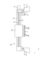
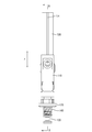
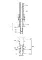
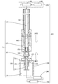
- a plan view of the component mounting apparatus Diagram showing the support structure of the head unit Front view of the head unit Front view of mounting shaft AA line sectional view of FIG. 4 Exploded view of the mounting shaft Diagram showing filter cleaning work Diagram showing the relationship between the sonic conductance of the air passage and the pressure change Diagram showing the relationship between the sonic conductance of the air passage and the pressure change Diagram showing the relationship between the sonic conductance of the air passage and the pressure change Diagram showing the relationship between the sonic conductance of the air passage and the pressure change Diagram showing the relationship between the sonic conductance of the air passage and the pressure change Block diagram showing the electrical configuration of the component mounting apparatus Flow chart showing the flow of maintenance processing Diagram showing removal operation of suction nozzle Diagram showing attachment operation of suction nozzle Diagram showing the test equipment In another embodiment, a cross-sectional view of the mounting shaft In another embodiment, a diagram showing a filter cleaning operation In another embodiment, a flowchart showing a flow of maintenance processing
- the component mounting device 1 has a base 11, a transfer conveyor 20 for transferring a substrate P, a head unit 60, and a head unit 60 on the base 11 in a planar direction. And a drive device 30 for moving in the (XY direction).
- the longitudinal direction of the base 11 (left and right direction in FIG. 1) is referred to as X direction
- the depth direction of the base 11 (vertical direction in FIG. 1) is Y direction
- the transfer conveyor 20 is disposed at the center of the base 11.
- the conveyer 20 includes a pair of conveyer belts 21 that are driven to circulate in the X direction, and conveys the substrate P on the conveyer belt 21 indicated by the two-dot chain line in the X direction by friction with the belt.
- the left side shown in FIG. 1 is the entrance, and the substrate P is carried from the upstream machine onto the base 11 from the left side shown in FIG.
- the loaded substrate P is conveyed by the transfer conveyor 20 to the work position G in the center of the base and stopped there.
- Supply devices 13A to 13D are provided on the base 11 so as to surround the work position G.
- a large number of feeders F for supplying small electronic components E such as chip resistors are installed side by side in the feeders 13A to 13D.
- the mounting shaft 100 mounted on the head unit 60 performs the mounting process of mounting the electronic component E supplied by the feeder disposed in the supply devices 13A to 13D on the substrate P.
- the substrate P which has finished all the work in the component mounting apparatus 1 is conveyed rightward in FIG. 1 through the conveyor 20 and is carried out to the downstream machine.
- the driving device 30 roughly includes a pair of support legs 41, a head support 51, a Y-axis ball screw 45, a Y-axis motor 47, an X-axis ball screw 55, and an X-axis motor 57.
- a pair of support legs 41 are installed on the base 11. Both support legs 41 are located on both sides in the X direction of the working position G, and both extend straight in the Y direction.
- a Y-axis ball screw 45 extending in the Y direction is attached to the right support leg 41, and a ball nut (not shown) is screwed into the Y-axis ball screw 45.
- a Y-axis motor 47 is attached to the Y-axis ball screw 45.
- the head support 51 is long in the X direction. As shown in FIG. 2, a guide member 53 extending in the X direction is installed on the head support 51, and the head unit 60 is attached to the guide member 53 so as to be movable along the axis of the guide member 53. It is done. An X-axis ball screw 55 extending in the X direction is attached to the head support 51, and a ball nut is screwed to the X-axis ball screw 55.
- an X-axis motor 57 is attached to the X-axis ball screw 55, and the head unit fixed to the ball nut as a result of the ball nut advancing and retracting along the X-axis ball screw 55 when the motor 57 is energized. 60 moves in the X direction along the guide member 53 (X axis servo mechanism).
- a plurality of mounting shafts 100 are mounted in a row on the head unit 60 as shown in FIGS. Each mounting shaft 100 extends in the vertical direction, and a suction nozzle 120 for suctioning the electronic component E is attached to the tip. Each mounting shaft 100 is configured to be able to move up and down relative to the head unit 60 by rotation around the axis by the R-axis motor 70 and driving of the Z-axis motor 77.
- the head unit 60 is provided with a pressure switching unit 81.
- the pressure switching unit 81 is provided for each mounting shaft 100, and is connected to the air passage La of the mounting shaft 100 via the air tube 85.
- the air passage La of each mounting shaft 100 is connected to an air source 83 via a pressure switching unit 81.
- a pressure switching unit 81 By switching the pressure switching unit 81, positive pressure or negative pressure can be supplied from the air source 83 to the mounting shaft 100 (see FIG. 7).
- the suction holding of the electronic component by the suction nozzle 120 becomes possible. Further, by supplying a positive pressure, the air filter 150 disposed in the middle of the air passage L of the mounting shaft 100 can be cleaned.
- the component mounting apparatus 1 operates the X-axis motor 57, the Y-axis motor 47, and the Z-axis motor 77 at a predetermined timing to take out the electronic component E supplied by the feeder F by the mounting shaft 100. It is possible to execute the processing loaded on top.
- a second camera H2 is installed on the base 11.
- the second camera H2 is fixed on the base 11 with the imaging surface facing upward.
- the second camera H2 is provided for image recognition of the electronic component E taken out of the feeder F.
- FIG. 4 is a front view of the mounting shaft 100
- FIG. 5 is a cross-sectional view of the mounting shaft 100
- FIG. 6 is a cross-sectional view of a state in which the suction nozzle 120 is separated from the mounting shaft 100.
- the mounting shaft 100 is, for example, made of metal and is axially shaped along the vertical direction (Z direction).
- a shaft cover 110 is provided at the lower part of the outer periphery of the mounting shaft 100.
- An air filter 150 is disposed in the middle of an air passage La provided inside the mounting shaft 100.
- the air filter 150 is disposed at the distal end portion 103 of the mounting shaft 100, and is in a relationship of being located in the first accommodation hole 123 of the nozzle holder 121.
- the air filter 150 is provided to suppress suction of foreign matter such as minute dust from the tip of the nozzle to the inside of the air passage L1 when the electronic component E is sucked by the suction nozzle 120.
- the air filter 150 is made of, for example, glass fiber or non-woven fabric.
- the suction nozzle 120 includes a nozzle holder 121, a nozzle body 131, and a coil spring 140.
- the nozzle body 131 is in the form of a long cylinder in the vertical direction (Z direction).
- An air passage L3 is provided at the axial center of the nozzle body 131.
- the air passage L3 is provided to penetrate the nozzle body 131 in the vertical direction (Z direction).
- the cross-sectional area of the air passage L3 is substantially constant over the entire length of the nozzle body 131.
- the nozzle body 131 is fitted into the second accommodation hole 124 of the nozzle holder 121 from below.
- the air passage La of the mounting shaft 100 is located above the air passage L3 of the nozzle body 131.
- the nozzle body 131 is displaceable in the vertical direction (Z direction) with respect to the nozzle holder 121.
- the coil spring 140 is attached to the outer peripheral side of the nozzle body 131. The coil spring 140 pushes the nozzle body 131 downward with respect to the nozzle holder 121.
- the nozzle holder 121 and the nozzle body 131 are separate parts and providing a coil spring 140 between the two, when a load is applied to the tip of the nozzle body 131, the coil spring 140 is shrunk to cause an impact. It can be absorbed.
- the suction nozzle 120 is attached in a state of being fitted to the distal end portion 103 of the mounting shaft 100, and can be removed from the mounting shaft 100 as shown in FIG.
- the component mounting device 1 has a cleaning device 200 for the air filter 150.
- the cleaning device 200 includes a positive pressure supply device 210, a dust collection unit 230, a filter 240, and a suction device 250.
- the positive pressure supply device 210 is composed of a pressure switching unit 81 and an air source 83.
- the pressure switching unit 81 is mounted on the head unit 60, and is provided for each of the mounting shafts 100. Each pressure switching unit 81 is commonly connected to the air source 83.
- the air passage La of the mounting shaft 100 is connected to an air source 83 via a pressure switching unit 81.
- the pressure switching unit 81 can switch which of positive pressure and negative pressure is supplied from the air source 83 to the air passage La of the mounting shaft 100.
- the positive pressure supply device 210 is an example of the “first supply device” in the present invention.
- the air passage Lv through which the cleaning air flows is, as shown in FIG. 7, a dust collection unit from the pressure switching unit 81 via the air passage La of the mounting shaft 100, the air filter 150, and the air passage L3 of the suction nozzle 120. It is a passage to 230.
- the cleaning device 200 cleans the air filter 150 by simultaneously supplying a positive pressure and a negative pressure to the air filter 150 from both sides of the air passage Lv for cleaning in the dust collection unit 230. Specifically, positive pressure is supplied from the side of the pressure switching portion 81 corresponding to one end side of the cleaning air passage Lv, and negative pressure is supplied from the side of the dust collection portion 230 corresponding to the other end side of the cleaning air passage Lv. Thus, the air filter 150 is cleaned.
- the sonic conductance C, the effective cross-sectional area S, and the pressure change are defined by the International Organization for Standardization in accordance with ISO 6358 [Pneumatic-Compressible Fluid Using Equipment-Determination of Fluid Characteristics] and JIS B 8390 [Pneumatic- It shall be defined, measured and calculated based on the flow characteristics test method of compressible fluid devices.
- the sonic conductance C is the conductance in the choke flow.
- the choke flow is a flow of gas whose velocity is locally the speed of sound in at least one cross section of equipment or piping and whose Mach number is equal to one.
- Conductance is a measure of the ability of a pneumatic device or tubing to flow gas.
- an air passage L1 a range from the pressure switching portion 81 to the air filter 150 disposed in the air passage La of the mounting shaft 100 from the air filter 150 is referred to as an air passage L1.
- an air filter disposition portion in which the air filter 150 is disposed is referred to as L2.
- the air passage downstream of the air filter 150, that is, the air passage of the suction nozzle 120 is L3, and the air passage of the dust collection unit 230 is L4.
- the sonic conductances C1 to C4 of the air passages L1 to L4 constituting the cleaning air passage Lv can be measured by a differential pressure type flow characteristic test based on JIS B8390.
- FIG. 16 is a view showing a test apparatus 401 of the sonic conductance C.
- the test apparatus 401 includes, for example, a pressure control valve 402, a shutoff valve 403, a flow meter 404, a thermometer 405, an upstream pressure measurement pipe 406, a test object (pneumatic device or piping) 408, a downstream pressure measurement pipe 410, an upstream pressure gauge 411, a downstream pressure gauge 412 and a flow control valve 413 are provided.
- the upstream pressure is maintained as high as possible, not less than 500 [kPa].
- the pressure regulator valve 402 is adjusted to keep the upstream pressure at a constant value during the test. Also, measure the atmospheric pressure with a barometer (not shown).
- the flow control valve 413 is opened to reduce the downstream pressure to a low value as much as possible. In this state, most of the specimens 408 are in a choked state.
- the upstream temperature, upstream pressure, mass flow rate, and downstream pressure of the choke flow state are measured.
- the flow control valve 413 is closed little by little in order to obtain two or more measurements in the choked state. And each measured value is measured similarly to the above. It is recommended to allow sufficient time for the system to stabilize and not to measure in the case of a continuously fluctuating flow rate.
- the sonic conductance C of the specimen 408 can be determined by the average value of the sonic conductance C i at each measurement point, as shown by the following Equation 1:
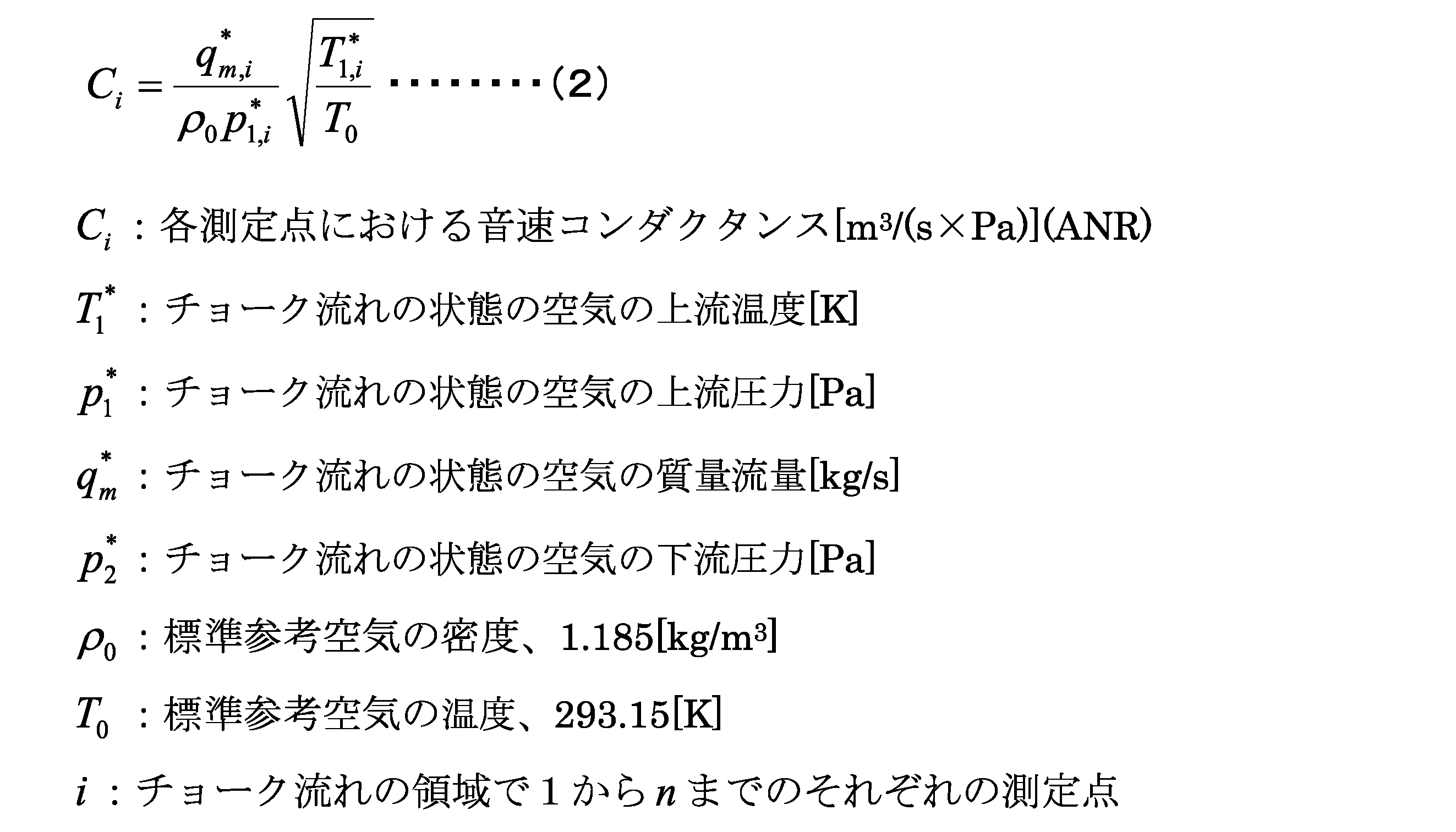
- the sonic conductance C i at each measurement point can be calculated from each measurement value according to Equation 2 below.
- the ANR attached to the unit indicates the state of standard reference air.
- FIGS. 8 to 11 (a) are side views of the cleaning air passage Lv.
- FIGS. 8 to 11B show the sonic conductances C1 to C4 of the air passages L1 to L4, respectively.
- the sonic conductance C [dm 3 / (s ⁇ bar)] is closely related to the effective cross-sectional area S [mm 2 ] of the air passage L, and when the critical pressure ratio is 0.5, It can be written.
- FIGS. 8 to 11B are diagrams showing the magnitude relationship of the sonic conductances C1 to C4 using the effective cross-sectional area of the conduit in order to make the sonic conductance C easily understandable. That is, the larger the sonic conductance C, the larger the effective cross-sectional area (represented by the diameter) of the conduit.
- FIGS. 8 to 11C are diagrams showing pressure changes in the cleaning air passage Lv.
- the pressure change is a change in the case where only a positive pressure is applied to the air passage Lv.
- FIGS. 8 to 11 differ from one another in the magnitude relationship of the sonic conductances C1 to C4 of the respective portions of the air passages L1 to L4. Equations (4) to (7) below respectively show the magnitude relationship of the sonic conductances C1 to C4 for each air passage L shown in FIGS. 8 to 11.
- C1 is the sonic conductance of the air passage L1 from the pressure switching unit 81 to the air filter 150.
- C2 is the sonic conductance of the air filter arrangement portion L2 including the air filter 150. That is, it is the sonic conductance in the air filter 150 and the placement portion L2.
- C3 is the sonic conductance of the air passage L3 of the suction nozzle 120.
- C4 is a sonic conductance of the air passage L4 in the dust collection unit 230.
- the inlet of the air filter 150 when the sonic conductance C2 of the air filter arrangement portion L2 including the air filter 150 is smaller than the sonic conductances C1, C3, C4 of the other air passages L1, L3, L4, the inlet of the air filter 150.
- the inlet and the outlet of the air filter 150 are respectively determined on the basis of the air flow direction (vertical direction in FIG. 8) when applying a positive pressure at the time of cleaning. The same applies to the upstream and downstream, and the upper side of FIG. 8 is the upstream and the lower side is the downstream.
- the sonic conductance C1 of the air passage L1 of the mounting shaft 100 or the sonic conductance C3 of the air passage L3 of the suction nozzle 120 is the air filter installation portion L2 including the air filter 150.
- a large difference can not be made between the pressure V1 at the inlet portion P1 of the air filter 150 and the pressure V2 at the outlet portion P2.
- the magnitude relationship of the sonic conductances C1 to C4 of each portion in the air passage L as shown in the equation (4). That is, it is preferable that the sonic conductance C2 of the air filter arrangement portion L2 including the air filter 150 be minimized on the air passages L1 to L4 through which the cleaning air flows.
- the sonic conductance C2 of the air filter arrangement portion L2 including the air filter 150 is smaller than the sonic conductance C1 of the upstream air passage L1.
- the size, thickness, material and mesh size (fineness) of the air filter 150 are selected.
- the suction nozzle 120 has a plurality of types with different sizes. That is, there are a plurality of types in which the sound velocity conductance C3 of the air passage L3 is different, and the sound velocity conductance C3 of the air passage L3 is larger than the sound velocity conductance C2 of the installation location of the air filter 150. There is a suction nozzle 120B with a small C3.
- suction nozzle 120 It is necessary to select which kind of suction nozzle 120 is used according to the type of electronic component E mounted on the substrate P.
- the component mounting device 1 cleans the air filter 150 without replacing the nozzle when the mounting shaft 100 to be cleaned is equipped with the suction nozzle 120A having a large sound velocity conductance C3.
- the suction nozzle 120B is installed at the nozzle exchange station 270 disposed adjacent to the dust collection unit 230 on the base. After replacing the suction nozzle 120A, the air filter 150 is cleaned.
- the dust collecting portion 230 is an air outlet at the time of positive pressure supply, and is set such that the sonic conductance C4 is maximized in the air passages L1 to L4.
- the controller 300 is a control unit of the component mounting apparatus 1 and includes an arithmetic processing unit 311 configured by a CPU or the like, and further includes a mounted program storage unit 313, a motor control unit 315, an image processing unit 316, a storage unit 317, and input / output. It has a part 319.
- An operation panel 320 is connected to the arithmetic processing unit 311, and various input operations can be performed via the operation panel 320.
- the loading program storage unit 313 stores a loading program for controlling a servo mechanism including the X-axis motor 57, the Y-axis motor 47, the Z-axis motor 77, the R-axis motor 70 and the like.
- the motor control unit 315 together with the arithmetic processing unit 311, drives various motors in accordance with the installation program, and various motors 57, 47, 77, 70 are electrically connected to the motor control unit 315.
- the first camera H1 and the second camera H2 are electrically connected to the image processing unit 316, and image data output from each of the cameras H1 and H2 is captured.
- the cleaning device 200 is electrically connected to the controller 300 via the input / output unit 319.
- the controller 300 uses the cleaning device 200 to clean the air filter 150 disposed in the middle of the air passage L of the mounting shaft 100 while the component mounting device 1 stops production.
- the storage unit 317 stores information necessary for cleaning the filter 150, for example, information on the previous execution time of the cleaning operation. Note that production means that the electronic component E is mounted on the substrate P carried onto the base 11.
- FIG. 13 is a flowchart of the maintenance process performed while the production of the substrate P is stopped.
- the controller 300 first determines whether the maintenance process is the first process (S10).
- the controller 300 executes the cleaning process (S30 to S70) of the air filter 150.
- the controller 300 first performs a process of selecting the uncleaned mounting shaft 100 (S30).
- the controller 300 performs a process of determining the type of the suction nozzle 120 mounted on the mounting shaft 100 selected as the cleaning target (S40).
- the type of suction nozzle 120 can be determined, for example, by image recognition of the shape or identification mark of the target suction nozzle 120 with the second camera H2.
- the controller 300 executes the cleaning operation of the air filter 150 ( S60).
- the head unit 60 is moved to move the mounting shaft 100 selected as the cleaning target right above the dust collection unit 230 disposed on the base 11. Thereafter, the Z-axis motor is driven to lower the mounting shaft 100, and the suction head 120A attached to the tip is inserted into the inside of the dust collection portion 230 through the insertion hole 235.
- the cleaning device 200 is driven to form the air passage Lv.
- the air filter 150 disposed under the air passage La of the mounting shaft 100 can be cleaned.
- the tip of the suction nozzle 120 can be taken out from the dust collection unit 230 by driving the Z-axis motor to raise the cleaned mounting shaft 100.
- the cleaning operation of the air filter 150 for the first mounting shaft 100 is completed.
- controller 300 performs a process of determining whether or not the cleaning work has been completed for all the mounting shafts 100 mounted on the head unit 60 (S70).
- the controller 300 When the second selected mounting shaft 100 is equipped with the suction nozzle 120A having a large sound velocity conductance C3 like the first mounting shaft, the controller 300 performs nozzle replacement like the first mounting shaft 100. Then, the air filter 150 is cleaned (S60).
- the controller 300 sets the suction nozzle 120B mounted on the mounting shaft 100 to a nozzle It moves to the exchange station 270, and exchanges it for the adsorption nozzle 120A having a large sonic conductance C3 (S50).
- the Z-axis motor is driven to lower the mounting shaft 100 from the state in which the suction nozzle 120 is in the vertical direction, and the tip portion L1 in the first accommodation hole 123 of the nozzle holder 121. Can be attached to the mounting shaft 100.
- the air filter 150 can be cleaned by simultaneously supplying positive pressure and negative pressure to the air filter 150 from both sides (S60).
- the controller 300 moves the mounting shaft 100 after cleaning to the nozzle replacement station 270, and the replaced nozzle is replaced by the original suction nozzle 120. Perform work to replace it.
- the air filters 150 disposed on the air passages of the mounting shafts 100 mounted on the head unit 60 can be cleaned one by one.
- the production of the substrate P is resumed in the component mounting apparatus 1. Then, when the production of the component mounting device 1 is stopped, the maintenance process (S10 to S70) shown in FIG. 13 is executed again.
- processing is performed to determine whether a prescribed time (for example, about one week) has elapsed from the end of the previous cleaning operation. Then, when the prescribed time has not elapsed from the end of the previous cleaning operation (S20: NO), the cleaning process is not executed, and the maintenance process is ended.
- a prescribed time for example, about one week
- the processing of S30 to S70 is executed, and the cleaning processing of the air filter 150 is automatically performed. From the above, the cleaning operation of the air filter 150 can be periodically performed using the time during which the production of the substrate P is stopped.
- the air passage La of the mounting shaft 100 can be used to clean the air filter 150.
- the pressure difference V1-V2 between the inlet portion P1 and the outlet portion P2 of the air filter 150 is used to clean the air filter 150, so the cleaning ability of the filter 150 is high. Therefore, the life of the air filter 150 is long, and the frequency of replacement can be reduced.
- the cleaning process of the filter 150 is periodically performed, the dirt is hardly accumulated on the filter 150, and the life of the filter 150 can be extended.
- the air filter 150 is cleaned by simultaneously supplying the positive pressure and the negative pressure to the air filter 150 from both sides of the air passage L.
- the air filter 150 may be cleaned by supplying either positive pressure or negative pressure.
- positive pressure or negative pressure it is preferable to use positive pressure.
- the cleaning process of the filter 150 is performed when the specified time has elapsed from the end of the cleaning operation.
- the filter 150 may be cleaned.
- an execution switch may be provided in the operation unit 220, and a switch operation by the user may be executed as a trigger.
Landscapes
- Engineering & Computer Science (AREA)
- Manufacturing & Machinery (AREA)
- Microelectronics & Electronic Packaging (AREA)
- Robotics (AREA)
- Mechanical Engineering (AREA)
- Supply And Installment Of Electrical Components (AREA)
- Manipulator (AREA)
Abstract
基板上に電子部品を搭載する部品搭載装置1であって、内部にエア通路Lを有し、先端部に吸着ノズル120を取り付けた搭載シャフト100と、前記搭載シャフト100の前記エア通路Laの途中に設けられたエアフィルタ150と、前記搭載シャフト100の前記エア通路Laを一部に含む清掃用のエア通路Lvを通じて、前記エアフィルタ150に対して正圧又は負圧を供給する供給装置210、250を含み、前記エアフィルタ150に正圧又は負圧を加えたときの、前記エアフィルタ150の入口部分と出口部分の圧力差を利用して前記エアフィルタ150を清掃する清掃装置200と、を備える。
Description
本明細書で開示される技術は、電子部品を吸着保持する搭載シャフトの内部に設けられたエアフィルタを清掃する技術に関する。
プリント基板に電子部品を搭載する部品搭載装置は、電子部品を吸着保持する搭載シャフトを備えている。搭載シャフトは、電子部品の吸着を繰り返すため、電子部品に付着していたゴミや空気中の埃を吸い込み汚れる。下記特許文献1、2には、搭載シャフトの内部にエアフィルタを配置することにより、微小なゴミなどの異物を吸引することを抑制する構造が開示されている。
部品搭載装置は搭載の効率化のために、年々、ヘッドユニットに搭載する搭載シャフトの多連化、狭ピッチ化が進められており、スペースの制約が求められている。そのため、エアフィルタも小型化されていることから、フィルタの寿命も短くなっている。従って、エアフィルタの交換頻度が増し、部品搭載装置の稼働率を低下させる懸念があった。
本明細書で開示される技術は、上記の課題に鑑みて創作されたものであって、エアフィルタの交換頻度を下げることを目的とする。
本明細書で開示される技術は、基板上に電子部品を搭載する部品搭載装置であって、内部にエア通路を有し、先端部に吸着ノズルを取り付けた搭載シャフトと、前記搭載シャフトの前記エア通路の途中に設けられたエアフィルタと、前記搭載シャフトの前記エア通路を一部に含む清掃用のエア通路を通じて、前記エアフィルタに対して正圧又は負圧を供給する供給装置を含み、前記エアフィルタに正圧又は負圧を加えたときの、前記エアフィルタの入口部分と出口部分の圧力差を利用して前記エアフィルタを清掃する清掃装置と、を備える。
本構成では、搭載シャフトのエア通路を利用して、エアフィルタを清掃できる。しかも、エアフィルタの入口部分と出口部分の圧力差を利用して清掃する構成であるから、エアフィルタの清掃能力が高い。そのため、エアフィルタの寿命が長く、交換頻度を下げることが出来る。
本明細書で開示される部品搭載装置の一実施態様として、前記清掃装置による清掃時において、音速コンダクタンスは、前記清掃用のエア通路のうち、前記エアフィルタを含むエアフィルタ配置部が最も小さい、ことが好ましい。本構成では、エアフィルタの入口部分と出口部分の間に、大きな圧力差が発生することから、エアフィルタの清掃能力が高くなる。
本明細書で開示される部品搭載装置の一実施態様として、前記供給装置は、前記清掃用のエア通路の一端側から前記エアフィルタに対して正圧を供給する第1供給装置と、前記清掃用のエア通路の他端側から前記エアフィルタに対して負圧を供給する第2供給装置と、を含むとよい。この構成では、エアフィルタに正圧と負圧を同時に供給出来るので、エアフィルタの清掃能力が高くなる。
本明細書で開示される部品搭載装置の一実施態様として、前記清掃装置は、前記搭載シャフトの使用回数が規定回数に到達した場合、又は前回清掃時から規定時間が経過した場合に、前記エアフィルタの清掃を行う。この構成では、適切な頻度で定期的に清掃するため、エアフィルタに汚れが溜まり難く、エアフィルタの寿命を長くすることができる。
本明細書で開示される技術は、先端に吸着ノズルを有し、基板上に電子部品を搭載する搭載シャフトのエア通路の途中に配置されたエアフィルタの清掃方法であって、前記搭載シャフトの前記エア通路を一部に含む清掃用のエア通路を通じて、前記エアフィルタに対して正圧又は負圧を加えたときの、前記エアフィルタの入口部分と出口部分の圧力差を利用して、前記エアフィルタを清掃する。
本方法では、搭載シャフトのエア通路を利用して、エアフィルタを清掃できる。しかも、エアフィルタの入口部分と出口部分の圧力差を利用して清掃する構成であるから、エアフィルタの清掃能力が高い。そのため、エアフィルタの寿命が長く、交換頻度を下げることが出来る。
本明細書で開示されるエアフィルタの清掃方法の一実施態様として、前記吸着ノズルを交換又は取り外すことにより、前記エアフィルタを含むエアフィルタ配置部の音速コンダクタンスが、清掃用のエア通路上において最も小さくなるように調整してから、前記エアフィルタの清掃を行う。本構成では、エアフィルタの入口部分と出口部分の間に大きな圧力差が発生することから、エアフィルタの清掃能力が高くなる。
本明細書で開示される技術によれば、エアフィルタの寿命を長くして、交換頻度を下げることが出来る。
<実施形態1>
1.部品搭載装置の説明
部品搭載装置1は、図1に示すように、基台11と、基板Pを搬送する搬送コンベア20と、ヘッドユニット60と、ヘッドユニット60を基台11上にて平面方向(XY方向)に移動させる駆動装置30とを備えている。尚、以下の説明において、基台11の長手方向(図1の左右方向)をX方向と呼ぶものとし、基台11の奥行方向(図1の上下方向)をY方向、図2の上下方向をZ方向とする。
1.部品搭載装置の説明
部品搭載装置1は、図1に示すように、基台11と、基板Pを搬送する搬送コンベア20と、ヘッドユニット60と、ヘッドユニット60を基台11上にて平面方向(XY方向)に移動させる駆動装置30とを備えている。尚、以下の説明において、基台11の長手方向(図1の左右方向)をX方向と呼ぶものとし、基台11の奥行方向(図1の上下方向)をY方向、図2の上下方向をZ方向とする。
搬送コンベア20は、基台11の中央に配置されている。搬送コンベア20はX方向に循環駆動する一対の搬送ベルト21を備えており、搬送ベルト21上の二点鎖線で示した基板Pを、ベルトとの摩擦によりX方向に搬送する。
本実施形態では、図1に示す左側が入り口となっており、基板Pは、図1に示す左側より搬送コンベア20を通じて上流機から基台11上へ搬入される。搬入された基板Pは、搬送コンベア20により基台中央の作業位置Gまで運ばれ、そこで停止される。
基台11上には、作業位置Gの周囲を囲むようにして、供給装置13A~13Dが設けらている。供給装置13A~13Dには、チップ抵抗などの小型電子部品Eを供給するフィーダFが横並び状に多数設置されている。
そして、作業位置Gでは、供給装置13A~13Dに配置されたフィーダにより供給される電子部品Eを、基板P上に搭載する搭載処理が、ヘッドユニット60に搭載された搭載シャフト100により行われる。尚、部品搭載装置1での全作業を終えた基板Pは、コンベア20を通じて、図1における右方向に運ばれ、下流機に搬出される構成になっている。
駆動装置30は、大まかには一対の支持脚41、ヘッド支持体51、Y軸ボールネジ45、Y軸モータ47、X軸ボールネジ55、X軸モータ57から構成される。具体的に説明してゆくと、図1に示すように基台11上には一対の支持脚41が設置されている。両支持脚41は作業位置GのX方向両側に位置しており、共にY方向にまっすぐに延びている。
両支持脚41にはY方向に延びるガイドレール42が支持脚上面に設置されると共に、これら左右のガイドレール42に長手方向の両端部を嵌合させつつ、ヘット支持体51が取り付けられている。
また、右側の支持脚41にはY方向に延びるY軸ボールねじ45が装着され、更にY軸ボールねじ45にはボールナット(不図示)が螺合されている。そして、Y軸ボールねじ45にはY軸モータ47が付設されている。
Y軸モータ47を通電操作すると、Y軸ボールねじ45に沿ってボールナットが進退する結果、ボールナットに固定されたヘッド支持体51、ひいては次述するヘッドユニット60がガイドレール42に沿ってY方向に移動する(Y軸サーボ機構)。
ヘッド支持体51は、X方向に長い形状である。ヘッド支持体51には、図2に示すように、X方向に延びるガイド部材53が設置され、更に、ガイド部材53に対してヘッドユニット60が、ガイド部材53の軸に沿って移動自在に取り付けられている。このヘッド支持体51には、X方向に延びるX軸ボールねじ55が装着されており、更にX軸ボールねじ55にはボールナットが螺合されている。
そして、X軸ボールねじ55にはX軸モータ57が付設されており、同モータ57を通電操作すると、X軸ボールねじ55に沿ってボールナットが進退する結果、ボールナットに固定されたヘッドユニット60がガイド部材53に沿ってX方向に移動する(X軸サーボ機構)。
従って、X軸モータ57、Y軸モータ47を複合的に制御することで、基台11上において、ヘッドユニット60を平面方向(XY方向)に移動操作出来る構成となっている。
係るヘッドユニット60には、図2、3に示すように、搭載シャフト100が列をなして、複数個搭載されている。各搭載シャフト100は上下方向に延びており、先端部には電子部品Eを吸着するための吸着ノズル120が取り付けられている。各搭載シャフト100は、R軸モータ70による軸回りの回転と、Z軸モータ77の駆動によりヘッドユニット60に対して昇降可能な構成となっている。
また、図3に示すように、ヘッドユニット60には、圧力切換部81が設けられている。圧力切換部81は、搭載シャフト100ごとに設けられており、エアチューブ85を介して、搭載シャフト100のエア通路Laに接続されている。
そして、各搭載シャフト100のエア通路Laは、圧力切換部81を介して、エア源83に接続されている。圧力切換部81を切換操作することで、エア源83から、搭載シャフト100に対して、正圧又は負圧を供給することができる(図7参照)。
搭載シャフト100のエア通路Laに負圧を供給することで、吸着ノズル120による電子部品の吸着保持が可能となる。また、正圧を供給することで、搭載シャフト100のエア通路Lの途中に配置されたエアフィルタ150を清掃することが出来る。
図3に示すように、ヘッドユニット60には、撮像面を下に向けた状態で、第1カメラH1が固定されている。第1カメラH1は、上述のX軸サーボ機構、Y軸サーボ機構を駆動させることで、基台11上をヘッドユニット60と一体的に移動することから、基板P上の任意の位置の画像を撮像することが出来る。部品搭載装置1は、第1カメラH1により撮影した基板Pの画像に基づいて、作業位置Gに停止した基板Pの位置を認識する。
部品搭載装置1は、X軸モータ57、Y軸モータ47、Z軸モータ77を所定のタイミングで作動させることにより、フィーダFにより供給される電子部品Eを、搭載シャフト100により取り出して、基板P上に搭載する処理を実行することが出来る。
基台11上には、第2カメラH2が設置されている。第2カメラH2は、基台11上において撮像面を上に向けて固定されている。第2カメラH2は、フィーダFから取り出した電子部品Eを画像認識するために設けられている。
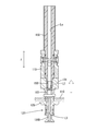
図4は搭載シャフト100の正面図、図5は搭載シャフト100の断面図である。図6は搭載シャフト100から吸着ノズル120を分離した状態の断面図である。
搭載シャフト100は、例えば、金属製であり、上下方向(Z方向)に沿った軸状である。搭載シャフト100の外周下部には、シャフトカバー110が設けられている。
搭載シャフト100の内部には、エア通路Laが設けられている。エア通路Laは、搭載シャフト100の軸線Lcに沿っており、搭載シャフト100を上下方向(Z方向)に貫通して設けられている。搭載シャフト100の内部に設けられたエア通路Laの断面積は、搭載シャフト100の全長に渡ってほぼ一定である。また、搭載シャフト100の先端部103には、吸着ノズル120が設けられている。
搭載シャフト100の内部に設けられたエア通路Laの途中には、エアフィルタ150が配置されている。エアフィルタ150は、搭載シャフト100の先端部103に配置されており、ノズルホルダ121の第1収容孔123内に位置する関係となっている。
エアフィルタ150は、吸着ノズル120により電子部品Eを吸着する際に、ノズル先端からエア通路L1の内部に、微小なゴミなどの異物を吸引することを抑制するために設けられている。エアフィルタ150は、例えば、ガラス繊維や不織布製である。
吸着ノズル120は、ノズルホルダ121と、ノズル本体131と、コイルばね140と、を備えている。
ノズルホルダ121は、例えば合成樹脂製であり、上下方向(Z方向)に長い筒型をしている。ノズルホルダ121には、第1収容孔123と第2収容孔124が上下に設けられている。第1収容孔123には、搭載シャフト100の先端部103が嵌合する。ノズルホルダ121の外周面には、突出部125が設けられている。
ノズル本体131は、上下方向(Z方向)に長い筒型である。ノズル本体131の軸芯には、エア通路L3が設けられている。エア通路L3は、ノズル本体131を上下方向(Z方向)に貫通して設けられている。エア通路L3の断面積は、ノズル本体131の全長に渡ってほぼ一定である。
ノズル本体131は、ノズルホルダ121の第2収容孔124に、下方から嵌合している。ノズル本体131のエア通路L3の上方に、搭載シャフト100のエア通路Laが位置している。
ノズル本体131は、ノズルホルダ121に対して、上下方向(Z方向)に変位自在である。コイルばね140は、ノズル本体131の外周側に取り付けられている。コイルばね140は、ノズルホルダ121に対して、ノズル本体131を下向きに押している。
ノズルホルダ121とノズル本体131とを別々の部品で構成し、両間にコイルばね140を設けておくことで、ノズル本体131の先端に荷重が加わったとき、コイルばね140が縮むことで衝撃を吸収することが出来る。
吸着ノズル120は、搭載シャフト100の先端部103に嵌合した状態で取り付けられていおり、嵌合を解くことで、図6に示すように、搭載シャフト100から取り外すことが出来る。
2.フィルタの清掃装置
部品搭載装置1は、エアフィルタ150の清掃装置200を有している。清掃装置200は、図7に示すように、正圧供給装置210と、集塵部230と、フィルタ240と、吸引装置250を有している。
部品搭載装置1は、エアフィルタ150の清掃装置200を有している。清掃装置200は、図7に示すように、正圧供給装置210と、集塵部230と、フィルタ240と、吸引装置250を有している。
正圧供給装置210は、圧力切換部81と、エア源83から構成されている。圧力切換部81は、ヘッドユニット60に搭載されており、搭載シャフト100ごとに設けられている。各圧力切換部81は、エア源83に対して、共通接続されている。
搭載シャフト100のエア通路Laは、圧力切換部81を介して、エア源83に接続されている。圧力切換部81は、エア源83から、搭載シャフト100のエア通路Laに対して、正圧又は負圧のどちらを供給するか、切り換えることができる。
圧力切換部81を正圧側に切り換えることで、エア源83から、搭載シャフト100のエア通路La、吸着ノズル120のエア通路L3に正圧を供給することが出来る。尚、正圧供給装置210が本発明の「第1供給装置」の一例である。
集塵部230は、例えば、金属製であり、基台11上に配置されている。集塵部230は、下面が開口する筒型である。集塵部230の上面壁には、挿入孔235が開口している。図7に示すように、挿入孔235から吸着ノズル120の先端部を、集塵部230の内部に挿入することが出来る。具体的には、吸着ノズル120のうち、突出部125より下のノズル先端を内部に挿入することが出来る。
吸引装置250はエアを吸引する装置であり、フィルタ240を介して、集塵部230に接続されている。そのため、吸引装置250を駆動すると、集塵部230の圧力が下がり、吸着ノズル120のエア通路L3、搭載シャフト100のエア通路Laに負圧を供給することが出来る。吸引装置250が本発明の「第2供給装置」の一例である。
清掃用のエアが流れるエア通路Lvは、図7に示すように、圧力切換部81から搭載シャフト100のエア通路La、エアフィルタ150、吸着ノズル120のエア通路L3を経由して、集塵部230に至る通路である。
清掃装置200は、集塵部230内において、清掃用のエア通路Lvの両側からエアフィルタ150に対して正圧と負圧を同時に供給することにより、エアフィルタ150の清掃を行う。具体的には、清掃用のエア通路Lvの一端側にあたる圧力切換部81側から正圧を供給し、清掃用のエア通路Lvの他端側にあたる集塵部230側から負圧を供給することにより、エアフィルタ150の清掃を行う。
以下の説明において、音速コンダクタンスC、有効断面積S、圧力変化は、国際標準化機構が定めているISO 6358[空気圧-圧縮性流体使用機器-流体特性の決定]とそれに準拠したJIS B8390[空気圧-圧縮性流体機器の流量特性試験方法]に基づいて定義、測定、計算されるものとする。
音速コンダクタンスCは、チョーク流れにおけるコンダクタンスである。チョーク流れとは、機器や配管の少なくとも1つの断面で速度が局所的に音速であり、マッハ数が1に等しい気体の流れである。コンダクタンスは、空気圧機器又は配管が気体を流す能力の程度である。
音速コンダクタンスCが大きい程、エアが通り易く、小さい程、エアが通り難い。また、エアの質量流量が同じであれば、音速コンダクタンスCが大きいほど、圧力勾配は小さくなる。
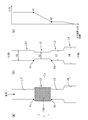
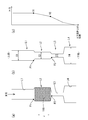
図8~図11は、エア通路Lvの音速コンダクタンスCと圧力変化の関係を示した図である。以下、清掃用のエア通路Lvのうち、エアフィルタ150より上流側、すなわち、圧力切換部81から搭載シャフト100のエア通路Laに配置されたエアフィルタ150までの範囲をエア通路L1とする。また、エア通路Laのうち、エアフィルタ150が配置されるエアフィルタ配置部をL2とする。そして、エアフィルタ150より下流側、すなわち吸着ノズル120のエア通路をL3とし、集塵部230のエア通路をL4とする。
清掃用のエア通路Lvを構成する、各エア通路L1~L4の音速コンダクタンスC1~C4は、JIS B8390に基づき、差圧式流量特性試験にて測定することができる。
<差圧式流量特性試験による音速コンダクタンスCの測定方法>
図16は、音速コンダクタンスCの試験装置401を示す図である。試験装置401は、例えば、圧力調整弁402、遮断弁403、流量計404、温度計405、上流圧力測定管406、供試体(空気圧機器や配管)408、下流圧力測定管410、上流の圧力計411、下流の圧力計412及び流量制御弁413を備える。
図16は、音速コンダクタンスCの試験装置401を示す図である。試験装置401は、例えば、圧力調整弁402、遮断弁403、流量計404、温度計405、上流圧力測定管406、供試体(空気圧機器や配管)408、下流圧力測定管410、上流の圧力計411、下流の圧力計412及び流量制御弁413を備える。
試験を行う場合、エア源から供試体408に空気を供給し、上流圧力を500[kPa]を下回らない、できるだけ高い一定に保持する。上流圧力を試験中、一定値に保つため、圧力調整弁402を調整する。また、図外の気圧計で大気圧を測定する。
そして最大流量を得るために、流量調整弁413を開き、下流圧力を可能な限り、低い値に減少させる。この状態で、ほとんどの供試体408は、チョーク流れの状態となる。
次に、チョーク流れの状態の上流温度、上流圧力、質量流量、下流圧力を測定する。チョーク流れの状態で2点以上の測定を得るために、少しずつ流量制御弁413を閉じる。そして、上記の同様に各測定値を測定する。システムが安定するまで十分に時間をおき、流量が連続的に変動する状態では、測定しないようにするとよい。
供試体408の音速コンダクタンスCは、下記の数式1で示すように、各測定点における音速コンダクタンスCiの平均値により決定することが出来る。各測定点における音速コンダクタンスCiは、各測定値から下記の数式2より計算することが出来る。尚、単位に付したANRは標準参考空気の状態を示す。

そして、各エア通路L1~L4を模擬した供試体408を用意し、上記の差圧式流量特性試験をそれぞれ行うことにより、清掃用のエア通路Lvを構成する各エア通路L1~L4の音速コンダクタンスC1~C4を求めることが出来る。
図8~図11の(a)は、清掃用のエア通路Lvの側面図である。図8~図11の(b)は、各エア通路L1~L4の音速コンダクタンスC1~C4を示す図である。
音速コンダクタンスC[dm3/(s×bar)]は、エア通路Lの有効断面積S[mm2]と密接な関係があり、臨界圧力比が0.5の場合、下記の式3にて表記することが出来る。
S=5.0×C・・・・・・・(3)
図8~図11の(b)では、音速コンダクタンスCを概念的に分かりやすくするため、管路の有効断面積を用いて、音速コンダクタンスC1~C4の大小関係を表現した図である。すなわち、音速コンダクタンスCが大きい程、管路の有効断面積(直径で表記)を大きく示している。
図8~図11の(C)は、清掃用のエア通路Lv内の圧力変化を示す図である。尚、圧力変化は、エア通路Lvに、正圧のみを加えた場合の変化である。
図8~図11は、エア通路L1~L4の各部位の音速コンダクタンスC1~C4の大小関係が異なっている。下記の(4)式~(7)式は、図8~図11に示す各エア通路Lについて、音速コンダクタンスC1~C4の大小関係をそれぞれ示している。
C4>C1≒C3>C2・・・・(4)
C4>C2>C1≒C3・・・・(5)
C4>C3>C2>C1・・・・(6)
C4>C1>C2>C3・・・・(7)
C4>C2>C1≒C3・・・・(5)
C4>C3>C2>C1・・・・(6)
C4>C1>C2>C3・・・・(7)
尚、C1は、圧力切換部81からエアフィルタ150までのエア通路L1の音速コンダクタンスである。C2は、エアフィルタ150を含むエアフィルタ配置部L2の音速コンダクタンスである。すなわち、エアフィルタ150及びその配置部L2における音速コンダクタンスである。C3は、吸着ノズル120のエア通路L3の音速コンダクタンスである。C4は集塵部230内のエア通路L4の音速コンダクタンスである。
図8に示すように、エアフィルタ150を含むエアフィルタ配置部L2の音速コンダクタンスC2が、他のエア通路L1、L3、L4の音速コンダクタンスC1、C3、C4よりも小さい場合、エアフィルタ150の入口部分P1の圧力V1と、出口部分P2の圧力V2に大きな差が出来る。尚、ここでは、清掃時に正圧をかける場合のエアの流れ方向(図8の上下方向)を基準として、エアフィルタ150の入口と出口をそれぞれ決めている。また、上流、下流も同様であり、図8の上側が上流、下側が下流である。
一方、図9~図11に示すように、搭載シャフト100のエア通路L1の音速コンダクタンスC1又は吸着ノズル120のエア通路L3の音速コンダクタンスC3の方が、エアフィルタ150を含むエアフィルタ設置部L2の音速コンダクタンスC2よりも小さい場合、エアフィルタ150の入口部分P1の圧力V1と、出口部分P2の圧力V2に大きな差が出来ない。
圧力差V1-V2が大きい程、清掃時(正圧供給時)、清掃装置200によるエアフィルタ150の清掃能力は高い。
したがって、エア通路Lにおける各部位の音速コンダクタンスC1~C4の大小関係を、(4)式のようにすることが好ましい。すなわち、エアフィルタ150を含むエアフィルタ配置部L2の音速コンダクタンスC2が、清掃用のエアが流れるエア通路L1~L4上において、最小にすることが好ましい。
本実施形態では、図8、図11に示すように、上流側のエア通路L1の音速コンダクタンスC1よりも、エアフィルタ150を含むエアフィルタ配置部L2の音速コンダクタンスC2の方が小さくなるように、エアフィルタ150の大きさ、厚さ、材料やメッシュサイズ(目の細かさ)を選択している。
吸着ノズル120には、サイズの異なる複数の種類がある。すなわち、エア通路L3の音速コンダクタンスC3が異なる複数の種類があり、エアフィルタ150の設置個所の音速コンダクタンスC2よりも、エア通路L3の音速コンダクタンスC3が大きい吸着ノズル120Aと、エア通路L3の音速コンダクタンスC3が小さい吸着ノズル120Bとがある。
どの種類の吸着ノズル120を使用するかは、基板Pに搭載する電子部品Eの種類に応じて選択する必要がある。
部品搭載装置1は、清掃対象の搭載シャフト100が、音速コンダクタンスC3の大きい吸着ノズル120Aを装着している場合、ノズルを交換せず、エアフィルタ150の清掃を行う。
一方、清掃対象の搭載シャフト100が、音速コンダクタンスC3の小さい吸着ノズル120Bを装着している場合、基台上において集塵部230に隣接して配置されたノズル交換ステーション270で、吸着ノズル120Bを吸着ノズル120Aに交換してから、エアフィルタ150の清掃を行う。
このようにすることで、エアフィルタ150の清掃時は、常に、エア通路Lの音速コンダクタンスCについて、(4)式の関係を維持することが可能であり、高い清掃能力を発揮できる。
尚、集塵部230は、正圧供給時のエア出口であり、エア通路L1~L4で、音速コンダクタンスC4が最大となるように設定されている。
3.部品搭載装置1の電気的構成
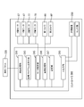
次に、部品搭載装置1の電気的構成を、図12を参照して説明する。部品搭載装置1はコントローラ300により装置全体が制御統括されている。
次に、部品搭載装置1の電気的構成を、図12を参照して説明する。部品搭載装置1はコントローラ300により装置全体が制御統括されている。
コントローラ300は、部品搭載装置1の制御部であり、CPU等により構成される演算処理部311を備える他、搭載プログラム記憶手段313、モータ制御部315、画像処理部316、記憶部317、入出力部319を有している。演算処理部311には、操作パネル320が接続されていて、操作パネル320を介して、各種の入力操作ができるようになっている。
搭載プログラム記憶手段313には、X軸モータ57、Y軸モータ47、Z軸モータ77、R軸モータ70などからなるサーボ機構を制御するための搭載プログラムが格納されている。
モータ制御部315は演算処理部311と共に、搭載プログラムに従って各種モータを駆動させるものであり、同モータ制御部315には、各種モータ57、47、77、70が電気的に連なっている。
画像処理部316には、第1カメラH1、第2カメラH2が電気的に連なっており、各カメラH1、H2から出力される画像データが、それぞれ取込まれるようになっている。
また、コントローラ300には、入出力部319を介して、清掃装置200が電気的に接続されている。コントローラ300は、部品搭載装置1が生産を停止している期間に、清掃装置200を使用して、搭載シャフト100のエア通路Lの途中に配置されたエアフィルタ150の清掃を行う。また、記憶部317には、フィルタ150の清掃作業を行うために必要な情報、例えば、清掃作業の前回実施時期の情報などが記憶されている。尚、生産とは、基台11上に搬入された基板Pに対して、電子部品Eを搭載することを意味する。
図13は、基板Pの生産停止中に実行されるメンテナンス処理のフローチャート図である。基板Pの生産が停止すると、まず、コントローラ300は、メンテナンス処理が初回かどうか判定する(S10)。
メンテナンス処理が初回の場合(S10:YES)、コントローラ300は、エアフィルタ150の清掃処理(S30~S70)を実行する。
具体的に説明すると、コントローラ300は、まず、未清掃の搭載シャフト100を選択する処理を行う(S30)。
次に、コントローラ300は、清掃対象として選択した搭載シャフト100に装着されている吸着ノズル120の種類を判定する処理を行う(S40)。
具体的には、音速コンダクタンスC3が大きい吸着ノズル120Aか、音速コンダクタンスC3が小さい吸着ノズル120Bか判定する。尚、吸着ノズル120の種類の判定は、例えば、第2カメラH2で、対象の吸着ノズル120の形状や識別マークを画像認識することで行うことが出来る。
清掃対象として選択された搭載シャフト100に搭載された吸着ノズル120が、音速コンダクタンスC3の大きい吸着ノズル120Aであった場合(S40:YES)、コントローラ300は、エアフィルタ150の清掃作業を実行する(S60)。
具体的には、ヘッドユニット60を移動して、清掃対象として選択された搭載シャフト100を、基台11上に配置された集塵部230の真上に移動する。その後、Z軸モータを駆動して搭載シャフト100を下降させて、先端に取り付けられた吸着ヘッド120Aを挿通孔235から集塵部230の内部に挿入する。
図7に示すように、集塵部230の内部に、吸着ノズル120のうち、突出部125よりも下の部分を収容することが出来たら、その後、清掃装置200を駆動してエア通路Lvの両側からエアフィルタ150に対して正圧と負圧を同時に供給することにより、搭載シャフト100のエア通路Laの下部に配置されたエアフィルタ150を清掃することができる。
エアフィルタ150の清掃後、Z軸モータを駆動して、清掃済みの搭載シャフト100を上昇させることにより、吸着ノズル120の先端部を集塵部230から取り出すことが出来る。これにて、1本目の搭載シャフト100について、エアフィルタ150の清掃作業が終了する。
その後、コントローラ300は、ヘッドユニット60に搭載された全ての搭載シャフト100について、清掃作業が終了したか判定する処理を行う(S70)。
未清掃の搭載シャフト100が残されている場合(S70:NO)、S30に移行し、コントローラ300は、未清掃の搭載シャフト100を選択する処理を行う。
2本目に選択された搭載シャフト100が、1本目と同様に、音速コンダクタンスC3の大きい吸着ノズル120Aを装着している場合、1本目の搭載シャフト100と同様に、コントローラ300は、ノズル交換を行うことなく、エアフィルタ150の清掃作業を行う(S60)。
一方、2本目に選択された搭載シャフト100が、音速コンダクタンスC3が小さい吸着ノズル120Bを装着している場合(S40:NO)、コントローラ300は、搭載シャフト100に装着された吸着ノズル120Bを、ノズル交換ステーション270に移動して、音速コンダクタンスC3が大きい吸着ノズル120Aに交換する(S50)。
尚、図14に示すように、板部材410の下面に対して、突出部125を突き当てた状態から、Z軸モータを駆動して、搭載シャフト100を上方に持ち上げることで、吸着ノズル120を取り外すことが出来る。
また、図15に示すように、吸着ノズル120を縦向きにした状態から、Z軸モータを駆動して、搭載シャフト100を下げてゆき、ノズルホルダ121の第1収容孔123内に先端部L1を嵌合させることで、搭載シャフト100に対して吸着ノズル120を取り付けることが出来る。
そして、ノズル交換後は、図7に示すように、集塵部230の内部に、吸着ノズル120Aのうち、突出部125よりも下の部分を収容することが出来たら、その後、エア通路Lvの両側からエアフィルタ150に対して正圧と負圧を同時に供給することにより、エアフィルタ150を清掃することができる(S60)。
S50にて、吸着ノズル120の交換作業を行った場合、吸着ノズル120の清掃後、コントローラ300は、清掃後の搭載シャフト100をノズル交換ステーション270に移動し、交換したノズルを元の吸着ノズル120に付け変える作業を実行する。
このような処理(S10~S70)を繰り返すことで、ヘッドユニット60に搭載された各搭載シャフト100のエア通路上に配置されたエアフィルタ150を、1つずつ清掃できる。
そして、ヘッドユニット60に搭載された全搭載シャフト100について、エアフィルタ150の清掃作業が完了すると、S70でNO判定されるため、全処理は終了する。
メンテナンス処理の終了後、部品搭載装置1にて、基板Pの生産が再開される。そして、部品搭載装置1の生産が停止すると、図13に示すメンテナンス処理(S10~S70)が、再び実行される。
2回目以降のメンテナン処理では、S20にて、前回の清掃作業終了から規定時間(一例として、1週間程度)が経過しているか否かを判断する処理が実行される。そして、前回の清掃作業終了から規定時間が経過していない場合(S20:NO)、清掃処理は実行されず、メンテナンス処理は終了する。
一方、前回の清掃作業終了から規定時間が経過している場合(S20:YES)、S30~S70の処理が実行され、エアフィルタ150の清掃処理が自動的に行われる。以上のことから、基板Pの生産が停止している時間を使用して、エアフィルタ150の清掃作業を定期的に行うことが出来る。
4.効果説明
本構成では、搭載シャフト100のエア通路Laを利用してエアフィルタ150を清掃できる。しかも、エアフィルタ150の入口部分P1と出口部分P2の圧力差V1-V2を利用して、エアフィルタ150を清掃する構成であるから、フィルタ150の清掃能力が高い。そのため、エアフィルタ150の寿命が長く、交換頻度を下げることが出来る。
本構成では、搭載シャフト100のエア通路Laを利用してエアフィルタ150を清掃できる。しかも、エアフィルタ150の入口部分P1と出口部分P2の圧力差V1-V2を利用して、エアフィルタ150を清掃する構成であるから、フィルタ150の清掃能力が高い。そのため、エアフィルタ150の寿命が長く、交換頻度を下げることが出来る。
また、清掃中、フィルタ150に正圧と負圧を同時に供給するので、フィルタ150の清掃能力が高い。
また、本構成では、フィルタ150の清掃処理が定期的に実行されるため、フィルタ150に汚れが溜まり難く、フィルタ150の寿命を長くすることができる。
以上、実施形態について詳細に説明したが、これらは例示に過ぎず、請求の範囲を限定するものではない。請求の範囲に記載の技術には、以上に例示した具体例を様々に変形、変更したものが含まれる。
(1)実施形態1では、エアフィルタ150を、搭載シャフト100の先端部103に配置した例を示した。エアフィルタ150の配置場所は、搭載シャフト100のエア通路Laの途中であれば、先端部以外であってもよい。例えば、図17に示すように、先端部103よりも上部側(清掃時に正圧供給装置210で正圧をかける場合において、エア流れ方向の上流側)に配置してもよい。
(2)実施形態1では、エア通路Lの両側からエアフィルタ150に対して正圧と負圧を同時に供給することにより、エアフィルタ150を清掃した。これ以外にも、正圧又は負圧のいずれか一方を供給することにより、エアフィルタ150を清掃するようにしてもよい。また、正圧又は負圧のいずれかを一方を用いる場合、正圧を用いることが好ましい。
(3)実施形態1では、清掃対象の搭載シャフト100が、音速コンダクタンスC3が小さい吸着ノズル120Bを装着している場合、吸着ノズル120Bを吸着ノズル120Aに交換してから、エアフィルタ150の清掃を行った。これ以外にも、図18に示すように、搭載シャフト100から音速コンダクタンスC3が小さい吸着ノズル120Bを取り外して、エアフィルタ150の清掃を行うようにしてもよい。吸着ノズル120Bを取り外した場合、(8)式で示すように、エアフィルタ150を含むエアフィルタ配置部L2の音速コンダクタンスC2が、清掃用のエアが流れるエア通路L1、L2、L4上において、最小になることから、交換時と同様の清掃能力を発揮することが出来る。
C4>C1>C2・・・・(8)式
(4)実施形態1では、清掃作業終了から規定時間が経過した場合に、フィルタ150の清掃処理を実行した例を示した。これ以外にも、例えば、図19に示すように、ヘッドユニット60に装着された複数の搭載シャフト100のうち、いずれかの搭載シャフト100の使用回数が規定回数に到達した場合(S25:YES)に、フィルタ150の清掃処理を実行するようにしてもよい。また、操作部220に実行スイッチを設けて、ユーザによるスイッチ操作をトリガに実行するようにしてもよい。
1...部品搭載装置
10...基台
60...ヘッドユニット
100...搭載シャフト
120...吸着ノズル
150...エアフィルタ
200...清掃装置
210...正圧供給装置(本発明の「第1供給装置」に相当)
230...集塵部
250...吸引装置(本発明の「第2供給装置」に相当)
270...ノズル交換ステーション
300...コントローラ
E...部品
P...基板
La...エア通路
Lc...軸線
C1~C4...音速コンダクタンス
Lv...清掃用のエア通路
L1~L4...エア通路
10...基台
60...ヘッドユニット
100...搭載シャフト
120...吸着ノズル
150...エアフィルタ
200...清掃装置
210...正圧供給装置(本発明の「第1供給装置」に相当)
230...集塵部
250...吸引装置(本発明の「第2供給装置」に相当)
270...ノズル交換ステーション
300...コントローラ
E...部品
P...基板
La...エア通路
Lc...軸線
C1~C4...音速コンダクタンス
Lv...清掃用のエア通路
L1~L4...エア通路
Claims (6)
- 基板上に電子部品を搭載する部品搭載装置であって、
内部にエア通路を有し、先端部に吸着ノズルを取り付けた搭載シャフトと、
前記搭載シャフトの前記エア通路の途中に設けられたエアフィルタと、
前記搭載シャフトの前記エア通路を一部に含む清掃用のエア通路を通じて、前記エアフィルタに対して正圧又は負圧を供給する供給装置を含み、前記エアフィルタに正圧又は負圧を加えたときの、前記エアフィルタの入口部分と出口部分の圧力差を利用して前記エアフィルタを清掃する清掃装置と、を備える、部品搭載装置。 - 請求項1に記載の部品搭載装置であって、
前記清掃装置による清掃時において、音速コンダクタンスは、前記清掃用のエア通路のうち、前記エアフィルタを含むエアフィルタ配置部が最も小さい、部品搭載装置。 - 請求項1又は請求項2に記載の部品搭載装置であって、
前記供給装置は、
前記清掃用のエア通路の一端側から前記エアフィルタに対して正圧を供給する第1供給装置と、
前記清掃用のエア通路の他端側から前記エアフィルタに対して負圧を供給する第2供給装置と、を含む、部品搭載装置。 - 請求項1~請求項3のいずれか一項に記載の部品搭載装置であって、
前記清掃装置は、前記搭載シャフトの使用回数が規定回数に到達した場合、又は前回清掃時から規定時間が経過した場合に、前記エアフィルタの清掃を行う、部品搭載装置。 - 先端に吸着ノズルを有し、基板上に電子部品を搭載する搭載シャフトのエア通路の途中に配置されたエアフィルタの清掃方法であって、
前記搭載シャフトの前記エア通路を一部に含む清掃用のエア通路を通じて、前記エアフィルタに対して正圧又は負圧を加えたときの、前記エアフィルタの入口部分と出口部分の圧力差を利用して、前記エアフィルタを清掃する、エアフィルタの清掃方法。 - 請求項5に記載のエアフィルタの清掃方法であって、
前記吸着ノズルを交換又は取り外すことにより、前記エアフィルタを含むエアフィルタ配置部の音速コンダクタンスが、清掃用のエア通路上において最も小さくなるように調整してから、前記エアフィルタの清掃を行う、エアフィルタの清掃方法。
Priority Applications (2)
| Application Number | Priority Date | Filing Date | Title |
|---|---|---|---|
| JP2019526067A JP6761124B2 (ja) | 2017-06-29 | 2017-06-29 | 部品搭載装置、エアフィルタの清掃方法 |
| PCT/JP2017/023970 WO2019003386A1 (ja) | 2017-06-29 | 2017-06-29 | 部品搭載装置、エアフィルタの清掃方法 |
Applications Claiming Priority (1)
| Application Number | Priority Date | Filing Date | Title |
|---|---|---|---|
| PCT/JP2017/023970 WO2019003386A1 (ja) | 2017-06-29 | 2017-06-29 | 部品搭載装置、エアフィルタの清掃方法 |
Publications (1)
| Publication Number | Publication Date |
|---|---|
| WO2019003386A1 true WO2019003386A1 (ja) | 2019-01-03 |
Family
ID=64742019
Family Applications (1)
| Application Number | Title | Priority Date | Filing Date |
|---|---|---|---|
| PCT/JP2017/023970 Ceased WO2019003386A1 (ja) | 2017-06-29 | 2017-06-29 | 部品搭載装置、エアフィルタの清掃方法 |
Country Status (2)
| Country | Link |
|---|---|
| JP (1) | JP6761124B2 (ja) |
| WO (1) | WO2019003386A1 (ja) |
Cited By (1)
| Publication number | Priority date | Publication date | Assignee | Title |
|---|---|---|---|---|
| CN113632601A (zh) * | 2019-04-23 | 2021-11-09 | 雅马哈发动机株式会社 | 元件安装装置 |
Citations (4)
| Publication number | Priority date | Publication date | Assignee | Title |
|---|---|---|---|---|
| JP2003224397A (ja) * | 2002-01-30 | 2003-08-08 | Fuji Mach Mfg Co Ltd | 電気部品保持装置のフィルタの目詰まり状態検査,清掃方法および装置 |
| JP2005191465A (ja) * | 2003-12-26 | 2005-07-14 | Yamaha Motor Co Ltd | 部品移載装置 |
| JP2006310816A (ja) * | 2005-03-30 | 2006-11-09 | Yamaha Motor Co Ltd | 部品移載装置、表面実装機および部品検査装置 |
| JP2007035871A (ja) * | 2005-07-26 | 2007-02-08 | Yamaha Motor Co Ltd | 表面実装機 |
-
2017
- 2017-06-29 JP JP2019526067A patent/JP6761124B2/ja active Active
- 2017-06-29 WO PCT/JP2017/023970 patent/WO2019003386A1/ja not_active Ceased
Patent Citations (4)
| Publication number | Priority date | Publication date | Assignee | Title |
|---|---|---|---|---|
| JP2003224397A (ja) * | 2002-01-30 | 2003-08-08 | Fuji Mach Mfg Co Ltd | 電気部品保持装置のフィルタの目詰まり状態検査,清掃方法および装置 |
| JP2005191465A (ja) * | 2003-12-26 | 2005-07-14 | Yamaha Motor Co Ltd | 部品移載装置 |
| JP2006310816A (ja) * | 2005-03-30 | 2006-11-09 | Yamaha Motor Co Ltd | 部品移載装置、表面実装機および部品検査装置 |
| JP2007035871A (ja) * | 2005-07-26 | 2007-02-08 | Yamaha Motor Co Ltd | 表面実装機 |
Cited By (3)
| Publication number | Priority date | Publication date | Assignee | Title |
|---|---|---|---|---|
| CN113632601A (zh) * | 2019-04-23 | 2021-11-09 | 雅马哈发动机株式会社 | 元件安装装置 |
| CN113632601B (zh) * | 2019-04-23 | 2023-05-09 | 雅马哈发动机株式会社 | 元件安装装置 |
| US12006968B2 (en) | 2019-04-23 | 2024-06-11 | Yamaha Hatsudoki Kabushiki Kaisha | Component mounting device |
Also Published As
| Publication number | Publication date |
|---|---|
| JP6761124B2 (ja) | 2020-09-23 |
| JPWO2019003386A1 (ja) | 2019-12-12 |
Similar Documents
| Publication | Publication Date | Title |
|---|---|---|
| CN106973516B (zh) | 基板的定位和传送 | |
| CN101489791B (zh) | 位置对准方法、网版印刷装置 | |
| JP5723221B2 (ja) | スクリーン印刷装置 | |
| CN104777711B (zh) | 清洁模块、清洁装置以及光掩模的清洁方法 | |
| KR101135838B1 (ko) | 스테이지 클리너, 묘화 장치 및 기판 처리 장치 | |
| US20120000380A1 (en) | Screen print system and method for cleaning a mask of the same | |
| CN104249547A (zh) | 位置检测装置、基板制造装置、位置检测方法及基板的制造方法 | |
| WO2016113864A1 (ja) | フィーダ保守装置及びフィーダ保守装置の制御方法 | |
| JP6761124B2 (ja) | 部品搭載装置、エアフィルタの清掃方法 | |
| CN110076823B (zh) | 检查方法 | |
| JP2008103405A (ja) | 実装機およびその部品清掃方法 | |
| JP6285501B2 (ja) | 実装ヘッドメンテナンス装置 | |
| TWI538039B (zh) | Processing means (B) | |
| KR100731518B1 (ko) | 피씨비 기판의 세정장치 및 세정방법 | |
| JP6814936B2 (ja) | 部品搭載装置、部品搭載装置のメンテナンス方法及び部品搭載方法 | |
| JP7431927B2 (ja) | 部品実装システム | |
| JP6902603B2 (ja) | 実装装置及び情報処理方法 | |
| JP7311269B2 (ja) | ノズルタップ装置 | |
| KR101583590B1 (ko) | 파티클 클리닝 모듈이 구비된 반송 시스템 | |
| CN111819701B (zh) | 用于生产半导体电池的设备、用于清洁印刷装置的印刷装置和用于在半导体生产设备中清洁印刷装置的方法 | |
| KR101981646B1 (ko) | 부품 탑재 장치 | |
| JP6850415B2 (ja) | フィーダ保守システム | |
| CN110326376B (zh) | 元件移载装置 | |
| JPWO2017037865A1 (ja) | 要求精度設定装置 | |
| JP7764185B2 (ja) | 基板作業機及び粘性体の深さの測定方法 |
Legal Events
| Date | Code | Title | Description |
|---|---|---|---|
| 121 | Ep: the epo has been informed by wipo that ep was designated in this application |
Ref document number: 17916400 Country of ref document: EP Kind code of ref document: A1 |
|
| ENP | Entry into the national phase |
Ref document number: 2019526067 Country of ref document: JP Kind code of ref document: A |
|
| NENP | Non-entry into the national phase |
Ref country code: DE |
|
| 122 | Ep: pct application non-entry in european phase |
Ref document number: 17916400 Country of ref document: EP Kind code of ref document: A1 |