WO2019003371A1 - 放射線撮影装置 - Google Patents
放射線撮影装置 Download PDFInfo
- Publication number
- WO2019003371A1 WO2019003371A1 PCT/JP2017/023868 JP2017023868W WO2019003371A1 WO 2019003371 A1 WO2019003371 A1 WO 2019003371A1 JP 2017023868 W JP2017023868 W JP 2017023868W WO 2019003371 A1 WO2019003371 A1 WO 2019003371A1
- Authority
- WO
- WIPO (PCT)
- Prior art keywords
- unit
- radiation
- switch
- ray
- imaging
- Prior art date
- Legal status (The legal status is an assumption and is not a legal conclusion. Google has not performed a legal analysis and makes no representation as to the accuracy of the status listed.)
- Ceased
Links
Images
Classifications
-
- A—HUMAN NECESSITIES
- A61—MEDICAL OR VETERINARY SCIENCE; HYGIENE
- A61B—DIAGNOSIS; SURGERY; IDENTIFICATION
- A61B6/00—Apparatus or devices for radiation diagnosis; Apparatus or devices for radiation diagnosis combined with radiation therapy equipment
Definitions
- the present invention relates to a radiation imaging apparatus such as an X-ray imaging apparatus provided with a foot switch for starting X-ray irradiation.
- Such an X-ray imaging apparatus is, for example, a console unit or a high voltage apparatus installed in an operation room for an operator to perform an X-ray imaging operation, and an imaging room for performing imaging on a subject. It comprises an imaging unit provided with an installed X-ray tube and a collimator and a examination table provided with an X-ray detector.
- a technician who is an operator in the imaging room guides the subject to the examination table and instructs the subject to a posture suitable for imaging, etc. After the engineer moves to the operation room, X-ray imaging is performed by pressing the hand switch in the high voltage device. On the other hand, when the subject can not take the posture at the time of imaging by himself, the technician performs imaging while assisting the subject.
- the assistance of the subject in the imaging room and the imaging operation in the operation room are shared.
- the assistance of the subject is required, for example, when the number of technicians is small due to the emergency response at night and the work can not be shared, one technician in the imaging room While assisting, X-ray imaging is performed by operating a foot switch installed in the imaging room.
- the foot switch used in such a case is conventionally provided with a two-step switch type switch. That is, in the conventional foot switch, the X-ray irradiator is in the standby state when the switch unit is depressed one step, and the X-ray is irradiated when the switch unit is further depressed to the second stage. . For this reason, when one technician in the imaging room operates the foot switch installed in the imaging room while assisting the subject, the operation of the foot switch becomes difficult.
- the technologist needs to press the switch portion of the foot switch to the first step while assisting the subject and hold the switch portion to the second step at the imaging timing while maintaining this state. Because there is something, the burden is large.
- the switch section should be kept pressed down to the first stage, if it is accidentally pressed down to the second stage, X-ray irradiation is started, and the subject and the technician do not need unnecessary exposure. It will be received.
- Patent Document 1 discloses an X-ray imaging apparatus including a foot switch provided with a sensor for detecting the proximity of the foot of a technician and the sensor detecting the foot of the technician when the sensor detects the foot of the technician. It is done.
- An object of the present invention is to provide a radiation imaging apparatus.
- the invention according to claim 1 is a radiation imaging apparatus comprising: a radiation irradiating unit that irradiates radiation; and a radiation detecting unit that detects radiation that has been irradiated from the radiation irradiating unit and has passed through a subject. And a radiation preparation unit that puts the radiation irradiation unit in a standby state by pressing a switch unit of the foot switch, a timer that starts measuring time based on an operation of the switch unit, and the timer And a radiation start unit configured to start radiation irradiation by the radiation irradiation unit when the switch unit is pressed again while the measured time is within the set time.
- the timer starts measuring time when the switch unit is pressed and then the switch unit is released.
- the invention according to claim 3 is the invention according to claim 2, wherein the irradiation preparation unit does not press the switch unit again while the time measured by the timer is within a set time. Release the standby state of the irradiation unit.
- the invention according to a fourth aspect is the invention according to the third aspect, wherein the set time is short as long as the operator can depress the switch portion again after releasing the depression of the switch portion. It is set.
- the setting time is set to a short time within a range where the operator can release the switch unit and then the switch unit can be pressed again, erroneous radiation of radiation It is possible to effectively prevent both the radiation irradiation unit and the consumption.
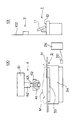
- FIG. 1 is a schematic view of an X-ray imaging apparatus according to the present invention. It is a perspective view of the examination stand 3 and the imaging part 4 in the X-ray imaging apparatus which concerns on this invention.
- FIG. 2 is a schematic view of a high voltage device 2; FIG. 2 is a perspective view of a foot switch 20.
- FIG. 2 is a block diagram showing a main control system of the X-ray imaging apparatus according to the present invention. It is a flowchart which shows X-ray imaging operation
- FIG. 1 is a schematic view of an X-ray imaging apparatus according to the present invention.
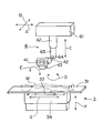
- FIG. 2 is a perspective view of the examination table 3 and the imaging unit 4 in the X-ray imaging apparatus according to the present invention.
- the console unit 1 and the high voltage apparatus 2 installed in the operation room 101 for the operator to execute an X-ray imaging operation, and the subject M for imaging
- the examination table 3 and the imaging unit 4 installed in the imaging room 100 are provided.
- the imaging room 100 and the operation room 101 are shut off by a partition 102.
- the console unit 1 installed in the operation room 101 includes a display unit 11 configured of a liquid crystal display or the like, and an operation unit 12 configured of a keyboard, a mouse or the like for performing various operations.
- An X-ray image or the like is displayed on the display unit 11.
- the console unit 1 is connected to an in-hospital network which is an in-hospital communication of a patient management system in a hospital (not shown).
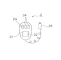
- FIG. 3 is a schematic view of the high voltage device 2.
- the high voltage device 2 is disposed in the partition 102 in the operation chamber 101.
- the high voltage device 2 starts the irradiation of X-rays from the X-ray tube 42 in the imaging unit 4 and the operation panel 21 having the display unit 22 composed of a touch panel liquid crystal display and the input button 24. And a hand switch 23.
- the high voltage device 2 is for setting the irradiation conditions of the X-ray such as the tube voltage and the tube current of the X-ray tube 42 or the X-ray irradiation time.
- the high voltage device 2 is connected to a high voltage generator 26 disposed in the photographing room 100.
- the high voltage generator 26 supplies the X-ray tube 42 with a high voltage to enable X-ray irradiation.
- the high voltage generator 26 is connected to a foot switch 20 used to start irradiation of X-rays in the imaging room 100.
- the screening table 3 is an X-ray detection in which a flat plate 31 on which the subject M is placed and a flat panel detector (FPD) as an X-ray detector housed inside And a lifting unit 34 for lifting and lowering the top 31 and the X-ray detection unit 33.
- the X-ray detection unit 33 is horizontally movable in the G direction shown in FIG. Further, the X-ray detection unit 33 can move up and down in the F direction shown in FIG. 2 together with the top 31.
- a table type examination table 3 for imaging the subject M on the top 31 in a lying position is adopted, and the X-ray detection unit 33 is horizontal in the G direction shown in FIG. It is configured to move.
- the X-ray detection unit 33 moves up and down.
- the photographing unit 4 has a base 61 movable in directions A and B orthogonal to the ceiling of the photographing room 100, a support 62 extending downward from the base 61, and the support A moving portion 63 which moves up and down in the C direction with respect to the portion 62 and is pivotally supported by a lower end portion of the moving portion 63 rotating in the D direction And a support shaft 64 which is rotated. Therefore, the handle 41, the X-ray tube 42, and the collimator 43 are movable in the A, B, C, D, and E directions.
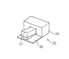
- FIG. 4 is a perspective view of the foot switch 20 described above.
- the foot switch 20 includes a base plate 28, a switch portion 27 disposed on the base plate 28, and a housing 29 in which electrical components and the like are accommodated.
- the switch unit 27 is used when performing X-ray irradiation from the X-ray irradiation unit.
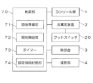
- FIG. 5 is a block diagram showing a main control system of the X-ray imaging apparatus according to the present invention.
- the X-ray imaging apparatus includes a CPU as a processor that executes logical operations, a RAM that temporarily stores data and the like at the time of control, and a ROM that stores operation programs necessary to control the apparatus.
- a control unit 70 for controlling is provided.
- the control unit 70 is connected to the console unit 1, the high voltage device 2, the examination table 3 and the imaging unit 4 described above, and exchanges signals with these units.
- the control unit 70 also includes an irradiation preparation unit 71 that starts the preparation for the X-ray irradiation by operating the hand switch 23 and the foot switch 20 in the high voltage device 2 and an irradiation start unit 72 that starts the X-ray irradiation. , A timer 73 for measuring time, and a set time storage unit 74 for storing a set time T described later.
- the timer 73 is configured to measure time by counting an internal clock of the CPU.
- a technician who is an operator in the imaging room 100 usually guides the subject M to the examination table 3.
- the hand switch 23 in the high voltage device 2 is X-ray imaging is performed by pressing.
- the technician performs imaging while assisting the subject M.
- the assistance of the subject M in the imaging room 100 and the imaging operation in the operation room 101 are shared.
- assistance from the subject M for example, when the number of technicians is small due to the emergency response at night and the work can not be shared, one technician in the imaging room 100
- the X-ray imaging is performed by operating the foot switch 20 installed in the imaging room 100 while assisting the examiner M.
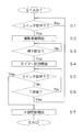
- FIG. 6 is a flowchart showing an X-ray imaging operation in the case where the technician alone performs the imaging assistance and the X-ray irradiation.
- the foot switch 20 installed in the imaging room 100 is used.
- the switch section 27 of the foot switch 20 shown in FIG. 4 is depressed (step S1). Since the switch unit 27 is not configured to press in two steps as in the conventional foot switch, the technologist can press the switch unit 27 without worrying about the degree of pressing.
- step S1 the preparation for X-ray irradiation is started by the instruction of the irradiation preparation unit 71 shown in FIG. 5 (step S2).
- step S2 filament heating is started in the X-ray tube 42, and the target starts to rotate, whereby the X-ray tube 42 and the like enter a standby state.
- the irradiation preparation is not started when the switch unit 27 is pressed for an extremely short time as in the case where the pressing time of the switch unit 27 is, for example, 10 ms (microseconds) or less.
- the engineer's foot accidentally touches the switch portion 27 of the foot switch 20, it becomes possible to prevent the radiation preparation from being started and to be in the standby state.
- the timer 73 starts measuring time (step S4) after the switch unit 27 is released (step S3). Then, after the depression of the switch unit 27 is released (step S3), when the switch unit 27 is depressed again (step S5), X-ray irradiation is started by the instruction of the irradiation start unit 72 shown in FIG. (Step S7). Thereby, X-ray imaging is performed.
- step S3 After the depression of the switch portion 27 is released (step S3), if the switch portion 27 is not pressed again even after the time T set in advance has elapsed (step S6), the irradiation preparation is performed.
- the unit 71 returns to the standby state by the command. This makes it possible to prevent the consumption of the X-ray tube 42 and the like due to the continuation of the standby state of the X-ray tube 42 and the like.
- the time T is set to a short time within a range in which the operator can release the switch unit 27 continuously after releasing the depression of the switch unit 27. That is, this time T is set as a short time such that the release and press of the switch portion 27 can be completed within the time T, as in the case of double click when using the mouse. For example, a time of about one second is set as the time T.
- the timer 73 starts measuring the time from the time the technologist performs pressing and releasing after pressing as the operation of the switch 27, the other operations of the switch 27 by the technologist
- the timer 73 may start measurement. For example, after the engineer presses the switch unit 27, the timer 73 may start measurement from the time when preparation for imaging is completed.
- the switch 73 is operated again while the time measured by the timer 73 is within the set time T. Since the X-ray irradiation from the X-ray tube 42 is started when the unit 27 is pressed, the burden on the technician can be reduced even when the technician performs X-ray imaging alone. It is possible to prevent radiation from being accidentally applied. Then, after the switch unit 27 is pressed, when the switch unit 27 is not pressed again while the time measured by the timer 73 is within the set time T, the standby state of the X-ray tube 42 etc. is released. It is possible to prevent the consumption of the X-ray tube 42 and the like due to the continuation of the standby state.
- the present invention is applied to an X-ray imaging apparatus using a table type examination table 3 for imaging the subject M on the top 31 in a lying position, but this invention
- Other X-ray imaging such as an X-ray imaging apparatus using a stand-type imaging table for imaging the subject M in a standing position, an X-ray imaging apparatus performing X-ray imaging and X-ray fluoroscopy, etc. It may be applied to the device.
- Reference Signs List 1 console unit 2 high voltage device 3 examination table 4 imaging unit 11 display unit 12 operation unit 20 foot switch 21 operation panel 22 display unit 23 hand switch 27 switch unit 31 top plate 33 X-ray detection unit 42 X-ray tube 43 collimator 70 control Part 71 Irradiation preparation part 72 Irradiation start part 73 Timer 74 Setting time storage part 100 Shooting room 101 Operation room M Subject
Landscapes
- Health & Medical Sciences (AREA)
- Life Sciences & Earth Sciences (AREA)
- Medical Informatics (AREA)
- Engineering & Computer Science (AREA)
- Radiology & Medical Imaging (AREA)
- Biomedical Technology (AREA)
- Biophysics (AREA)
- Nuclear Medicine, Radiotherapy & Molecular Imaging (AREA)
- Optics & Photonics (AREA)
- Pathology (AREA)
- Physics & Mathematics (AREA)
- High Energy & Nuclear Physics (AREA)
- Heart & Thoracic Surgery (AREA)
- Molecular Biology (AREA)
- Surgery (AREA)
- Animal Behavior & Ethology (AREA)
- General Health & Medical Sciences (AREA)
- Public Health (AREA)
- Veterinary Medicine (AREA)
- Apparatus For Radiation Diagnosis (AREA)
Abstract
制御部70におけるタイマー73は、フットスイッチ20におけるスイッチ部の押下が解除されたときから時間の計測を開始する。そして、スイッチ部の押下状態が解除された後、再度、スイッチ部が押下されたときには、X線照射を開始する。これにより、X線撮影が実行される。一方、スイッチ部の押下状態が解除された後、時間が予め設定された時間Tが経過しても再度スイッチ部が押圧されなかった場合には、待機状態に復帰する。
Description
この発明は、X線照射開始用のフットスイッチを備えたX線撮影装置等の放射線撮影装置に関する。
このようなX線撮影装置は、例えば、オペレータがX線撮影操作を実行するための操作室に設置されたコンソール部や高電圧装置と、被検者に対して撮影を行うための撮影室に設置されたX線管とコリメータとを備える撮影部やX線検出器を備える検診台とから構成される。
被検者に対するX線撮影を行うときには、一般的に、撮影室においてオペレータである技師が被検者を検診台に案内し、被検者に対して撮影に適した姿勢を指示する等の撮影の準備を行い、その後、技師が操作室に移動した後、高電圧装置におけるハンドスイッチを押圧することによりX線撮影を行う。一方、被検者が自力で撮影の際の姿勢をとることができないときには、技師が被検者の補助を行いながら撮影を実行する。
このような場合において、複数人の技師がいる場合には、撮影室における被検者の補助と操作室における撮影操作とを分担する。しかしながら、被検者の補助が必要となる場合において、例えば、夜間の救急対応などで技師の人数が少なく、作業を分担することができない場合においては、撮影室内で一人の技師が被検者の補助をしながら、撮影室内に設置されたフットスイッチを操作することによりX線撮影を実行する。
このような場合に使用されるフットスイッチは、従来、二段踏み込み式のスイッチ部を備えている。すなわち、従来のフットスイッチにおいては、スイッチ部を一段押下したときには、X線照射部がスタンバイ状態となり、スイッチ部をさらに二段目まで押下したときにX線が照射される構成が採用されている。このため、撮影室内で一人の技師が被検者の補助をしながら、撮影室内に設置されたフットスイッチを操作する場合においては、フットスイッチの操作が困難となる。
すなわち、技師は、被検者の補助をしながらフットスイッチのスイッチ部を一段目まで押下し、この状態を維持したまま、撮影タイミングとなったときにスイッチ部を二段目まで押下する必要があることから、その負担が大きい。また、スイッチ部を一段目まで押下したままとすべきときに、誤って二段目まで押下してしまった場合においては、X線の照射が開始され、被検者および技師が不要な被曝を受けることになる。
特許文献1においては、技師の足部の近接を検出するセンサを設け、このセンサが技師の足を検出したときにX線照射部をスタンバイ状態とするフットスイッチを備えたX線撮影装置が開示されている。
特許文献1に記載のX線撮影装置においては、技師の足部をセンサが検出するたびにX線照射部がスタンバイ状態となることから、X線照射部の寿命が短くなるという問題がある。すなわち、技師の足部をセンサが検出することにより、X線照射部を構成するX線管においてフィラメントが加熱され、あるいは、ターゲットが回転する動作等が実行されることになり、これらの部品が消耗する結果となる。また、技師の足部をセンサが検出した後、誤ってスイッチ部を押下してしまった場合においては、X線の照射が開始され、被検者および技師が不要な被曝を受けることになる。
この発明は上記課題を解決するためになされたものであり、技師の負担を軽減しながら、誤って放射線が照射されることを防止でき、また、放射線照射部の消耗を防止することが可能な放射線撮影装置を提供することを目的とする。
請求項1に記載の発明は、放射線を照射する放射線照射部と、前記放射線照射部から照射され被検者を通過した放射線を検出する放射線検出部と、を備えた放射線撮影装置において、フットスイッチと、前記フットスイッチにおけるスイッチ部が押下されることにより、前記放射線照射部をスタンバイ状態とする照射準備部と、前記スイッチ部の操作に基づいて、時間の計測を開始するタイマーと、前記タイマーにより計測された時間が設定時間内である間に再度前記スイッチ部が押下されたときに、前記放射線照射部による放射線照射を開始させる照射開始部と、を備えたことを特徴とする。
請求項2に記載の発明は、請求項1に記載の発明において、前記タイマーは、前記スイッチ部が押下された後、押下が解除されたときに、時間の計測を開始する。
請求項3に記載の発明は、請求項2に記載の発明において、前記照射準備部は、前記タイマーにより計測された時間が設定時間内である間に再度前記スイッチ部が押下されないときに、前記放射線照射部のスタンバイ状態を解除する。
請求項4に記載の発明は、請求項3に記載の発明において、前記設定時間は、オペレータが前記スイッチ部の押下を解除した後、再度スイッチ部を押下することができる範囲で、短い時間に設定される。
請求項1および請求項2に記載の発明によれば、スイッチ部が操作された後、タイマーにより計測された時間が設定時間内である間に再度スイッチ部が押下されたときに、放射線照射部による放射線照射を開始させることから、技師が単独で放射線撮影を実行する場合においても、技師の負担を軽減することができ、また、誤って放射線が照射されることを防止することが可能となる。
請求項3に記載の発明によれば、タイマーにより計測された時間が設定時間内である間に再度スイッチ部が押下されないときに、放射線照射部のスタンバイ状態を解除することから、スタンバイ状態が継続することによる放射線照射部の消耗を防止することが可能となる。
請求項4に記載の発明によれば、設定時間を、オペレータがスイッチ部の押下を解除した後、再度スイッチ部を押下することができる範囲で短い時間に設定することから、放射線の誤照射と放射線照射部の消耗との両方を、効果的に防止することが可能となる。
以下、この発明の実施の形態を図面に基づいて説明する。図1は、この発明に係るX線撮影装置の概要図である。また、図2は、この発明に係るX線撮影装置における検診台3および撮影部4の斜視図である。
この発明に係るX線撮影装置は、オペレータがX線撮影操作を実行するための操作室101に設置されたコンソール部1および高電圧装置2と、被検者Mに対して撮影を行うための撮影室100に設置された検診台3および撮影部4とを備える。撮影室100と操作室101とは、隔壁102により遮断されている。
操作室101に設置されたコンソール部1は、液晶表示器等から構成される表示部11と、各種の操作を実行するためのキーボードやマウス等からなる操作部12とを備える。表示部11には、X線撮影画像等が表示される。このコンソール部1は、図示を省略した病院内の被検者管理システムの院内通信である院内ネットワークと接続されている。
図3は、高電圧装置2の概要図である。
この高電圧装置2は、操作室101内において隔壁102に配設される。この高電圧装置2は、タッチパネル式の液晶表示器から構成される表示部22と入力ボタン24と有する操作パネル21と、撮影部4におけるX線管42からのX線の照射を開始するためのハンドスイッチ23とを備える。この高電圧装置2は、X線管42の管電圧や管電流、あるいは、X線照射時間等のX線の照射条件を設定するためのものである。この高電圧装置2は、撮影室100に配設された高電圧発生器26と接続されている。この高電圧発生器26は、X線管42に対して、X線の照射を可能とするための高電圧を供給する。なお、この高電圧発生器26は、撮影室100内においてX線の照射を開始するために使用されるフットスイッチ20と接続されている。
再度、図1および図2を参照して、検診台3は、被検者Mを載置する天板31と、内部にX線検出器としてのフラットパネルディテクタ(FPD)を収納したX線検出部33と、天板31およびX線検出部33を昇降するための昇降部34とを備える。X線検出部33は、図2に示すG方向に水平移動可能となっている。また、X線検出部33は、天板31とともに、図2に示すF方向に昇降可能となっている。
なお、この実施形態においては、天板31上の被検者Mを臥位状態で撮影するテーブル式の検診台3を採用しており、X線検出部33が図2に示すG方向に水平移動する構成となっている。これに対して、被検者Mを立位状態で撮影するスタンド式の撮影台を使用した場合には、X線検出部33は昇降することになる。
撮影部4は、図2に示すように、撮影室100の天井に対して互いに直交するA方向およびB方向に移動可能な基部61と、この基部61から下方に延びる支持部62と、この支持部62に対してC方向に昇降するともに、D方向に回動する移動部63と、この移動部63の下端部に軸支され、ハンドル41、X線管42およびコリメータ43を一体としてE方向に回動させる支持軸64とを備える。このため、ハンドル41、X線管42およびコリメータ43は、A、B、C、D、E方向に移動可能となっている。
図4は、上述したフットスイッチ20の斜視図である。
このフットスイッチ20は、ベース板28と、このベース板28上に配設されたスイッチ部27と、電機部品等が収納される筐体29とを備える。スイッチ部27はX線照射部からのX線の曝射を実行するときに使用される。
図5は、この発明に係るX線撮影装置の主要な制御系を示すブロック図である。
このX線撮影装置は、論理演算を実行するプロセッサーとしてのCPU、制御時にデータ等が一時的にストアされるRAM、装置の制御に必要な動作プログラムが格納されたROM等を備え、装置全体を制御する制御部70を備える。この制御部70は、上述したコンソール部1、高電圧装置2、検診台3および撮影部4と接続されており、これらとの間で信号をやり取りする。
また、この制御部70は、高電圧装置2におけるハンドスイッチ23やフットスイッチ20が操作されることによりX線の照射準備を開始する照射準備部71と、X線照射を開始させる照射開始部72と、時間を計測するタイマー73と、後述する設定時間Tを記憶する設定時間記憶部74とを備える。なお、タイマー73は、CPUの内部クロックをカウントすることにより時間を計測する構成を有する。
以上のような構成を有するX線撮影装置を使用して被検者Mに対するX線撮影を行うときには、通常は、撮影室100においてオペレータである技師が被検者Mを検診台3に案内し、天板31上において被検者Mに対して撮影に適した姿勢を指示する等の撮影の準備を行い、その後、技師が操作室101に移動した後、高電圧装置2におけるハンドスイッチ23を押圧することによりX線撮影を行う。一方、被検者Mが自力で撮影の際の姿勢をとることができないときには、技師が被検者Mの補助を行いながら撮影を実行する。
このような場合において、複数人の技師がいる場合には、撮影室100における被検者Mの補助と操作室101における撮影操作とを分担する。しかしながら、被検者Mの補助が必要となる場合において、例えば、夜間の救急対応などで技師の人数が少なく、作業を分担することができない場合においては、撮影室100内で一人の技師が被検者Mの補助をしながら、撮影室100内に設置されたフットスイッチ20を操作することによりX線撮影を実行する。
以下、技師が一人で撮影の補助とX線照射を実行する場合のX線撮影動作について説明する。図6は、技師が一人で撮影の補助とX線照射を実行する場合のX線撮影動作を示すフローチャートである。
技師が一人で被検者Mを補助しながらX線撮影を実行するときには、撮影室100内に設置されたフットスイッチ20が使用される。このときには、撮影の準備がある程度整えば、図4に示すフットスイッチ20におけるスイッチ部27を押下する(ステップS1)。このスイッチ部27は、従来のフットスイッチのように二段階に押下する構成ではないことから、技師は押下の程度を気にすることなくスイッチ部27を押下することができる。
スイッチ部27が押下されたときには(ステップS1)、図5に示す照射準備部71の指令によりX線照射を行うための照射準備を開始する(ステップS2)。これにより、X線管42においてフィラメント加熱が開始されるとともに、ターゲットが回転を開始することにより、X線管42等がスタンバイ状態となる。なお、スイッチ部27の押下時間が,例えば、10ms(マイクロセカンド)以下である場合のように、極めて短い時間しかスイッチ部27が押下されなかった場合においては、照射準備は開始されない。これにより、技師の足が誤ってフットスイッチ20におけるスイッチ部27に触れた場合等に、照射準備が開始され、スタンバイ状態となることを防止することが可能となる。
タイマー73は、スイッチ部27の押下が解除されたときから(ステップS3)、時間の計測を開始する(ステップS4)。そして、スイッチ部27の押下状態が解除された後(ステップS3)、再度、スイッチ部27が押下されたときには(ステップS5)、図5に示す照射開始部72の指令によりX線照射を開始する(ステップS7)。これにより、X線撮影が実行される。
一方、スイッチ部27の押下状態が解除された後(ステップS3)、時間が予め設定された時間Tが経過しても再度スイッチ部27が押圧されなかった場合には(ステップS6)、照射準備部71の指令により、待機状態に復帰する。これにより、X線管42等のスタンバイ状態が継続することによるX線管42等の消耗を防止することが可能となる。
この時間Tとしては、技師がスイッチ部27の押下を解除した後、再度、連続してスイッチ部27を押下することができる範囲で短い時間に設定される。すなわち、この時間Tは、スイッチ部27の押下解除と押下とを、マウスを使用するときのダブルクリックのように、T時間内に完了することができるような短い時間として設定される。この時間Tとしては、例えば、1秒程度の時間が設定されている。
なお、上記の説明においては、技師がスイッチ部27の操作として、押下の後に押下解除を行ったときからタイマー73が時間の計測を開始しているが、技師によるスイッチ部27のその他の操作によりタイマー73が計測を開始するようにしてもよい。例えば、技師がスイッチ部27を押下した後、撮影準備が完了した時点から、タイマー73が計測を開始するようにしてもよい。
以上のように、この発明に係るX線撮影装置によれば、スイッチ部27が操作され、その押下が解除された後、タイマー73により計測された時間が設定時間T内である間に再度スイッチ部27が押下されたときに、X線管42からのX線照射を開始させることから、技師が単独でX線撮影を実行する場合においても、技師の負担を軽減することができ、また、誤って放射線が照射されることを防止することが可能となる。そして、スイッチ部27が押下された後、タイマー73により計測された時間が設定時間T内である間に再度スイッチ部27が押下されないときに、X線管42等のスタンバイ状態を解除することから、スタンバイ状態が継続することによるX線管42等の消耗を防止することが可能となる。
なお、上述した実施形態においては、この発明を、天板31上の被検者Mを臥位状態で撮影するテーブル式の検診台3使用したX線撮影装置に適用しているが、この発明を、被検者Mを立位状態で撮影するスタンド式の撮影台を使用したX線撮影装置や、X線撮影とX線透視とを実行するX線撮影装置等の、その他のX線撮影装置に適用してもよい。
1 コンソール部
2 高電圧装置
3 検診台
4 撮影部
11 表示部
12 操作部
20 フットスイッチ
21 操作パネル
22 表示部
23 ハンドスイッチ
27 スイッチ部
31 天板
33 X線検出部
42 X線管
43 コリメータ
70 制御部
71 照射準備部
72 照射開始部
73 タイマー
74 設定時間記憶部
100 撮影室
101 操作室
M 被検者
2 高電圧装置
3 検診台
4 撮影部
11 表示部
12 操作部
20 フットスイッチ
21 操作パネル
22 表示部
23 ハンドスイッチ
27 スイッチ部
31 天板
33 X線検出部
42 X線管
43 コリメータ
70 制御部
71 照射準備部
72 照射開始部
73 タイマー
74 設定時間記憶部
100 撮影室
101 操作室
M 被検者
Claims (4)
- 放射線を照射する放射線照射部と、前記放射線照射部から照射され被検者を通過した放射線を検出する放射線検出部と、
を備えた放射線撮影装置において、
フットスイッチと、
前記フットスイッチにおけるスイッチ部が押下されることにより、前記放射線照射部をスタンバイ状態とする照射準備部と、
前記スイッチ部の操作に基づいて、時間の計測を開始するタイマーと、
前記タイマーにより計測された時間が設定時間内である間に再度前記スイッチ部が押下されたときに、前記放射線照射部による放射線照射を開始させる照射開始部と、
を備えたことを特徴とする放射線撮影装置。 - 請求項1に記載の放射線撮影装置において、
前記タイマーは、前記スイッチ部が押下された後、押下が解除されたときに、時間の計測を開始する放射線撮影装置。 - 請求項2に記載の放射線撮影装置において、
前記照射準備部は、前記タイマーにより計測された時間が設定時間内である間に再度前記スイッチ部が押下されないときに、前記放射線照射部のスタンバイ状態を解除する放射線撮影装置。 - 請求項3に記載の放射線撮影装置において、
前記設定時間は、オペレータが前記スイッチ部の押下を解除した後、再度スイッチ部を押下することができる範囲で、短い時間に設定される放射線撮影装置。
Priority Applications (1)
| Application Number | Priority Date | Filing Date | Title |
|---|---|---|---|
| PCT/JP2017/023868 WO2019003371A1 (ja) | 2017-06-29 | 2017-06-29 | 放射線撮影装置 |
Applications Claiming Priority (1)
| Application Number | Priority Date | Filing Date | Title |
|---|---|---|---|
| PCT/JP2017/023868 WO2019003371A1 (ja) | 2017-06-29 | 2017-06-29 | 放射線撮影装置 |
Publications (1)
| Publication Number | Publication Date |
|---|---|
| WO2019003371A1 true WO2019003371A1 (ja) | 2019-01-03 |
Family
ID=64740454
Family Applications (1)
| Application Number | Title | Priority Date | Filing Date |
|---|---|---|---|
| PCT/JP2017/023868 Ceased WO2019003371A1 (ja) | 2017-06-29 | 2017-06-29 | 放射線撮影装置 |
Country Status (1)
| Country | Link |
|---|---|
| WO (1) | WO2019003371A1 (ja) |
Citations (2)
| Publication number | Priority date | Publication date | Assignee | Title |
|---|---|---|---|---|
| JPH04246339A (ja) * | 1991-01-31 | 1992-09-02 | Shimadzu Corp | X線透視画像表示装置 |
| JP2013158418A (ja) * | 2012-02-03 | 2013-08-19 | Shimadzu Corp | フットスイッチおよび撮影装置 |
-
2017
- 2017-06-29 WO PCT/JP2017/023868 patent/WO2019003371A1/ja not_active Ceased
Patent Citations (2)
| Publication number | Priority date | Publication date | Assignee | Title |
|---|---|---|---|---|
| JPH04246339A (ja) * | 1991-01-31 | 1992-09-02 | Shimadzu Corp | X線透視画像表示装置 |
| JP2013158418A (ja) * | 2012-02-03 | 2013-08-19 | Shimadzu Corp | フットスイッチおよび撮影装置 |
Similar Documents
| Publication | Publication Date | Title |
|---|---|---|
| JP4793492B2 (ja) | X線撮影装置 | |
| JP5612011B2 (ja) | 放射線撮影システム、並びに放射線画像検出装置 | |
| JP7554746B2 (ja) | 改良された撮像方法 | |
| WO2012033029A1 (ja) | X線画像診断装置 | |
| WO2015011987A1 (ja) | X線撮影装置 | |
| JP6540348B2 (ja) | 放射線撮影システム | |
| JP2013066784A (ja) | 乳房撮影検査用x線診断装置 | |
| JP2003047608A (ja) | X線撮影装置 | |
| JP6540827B2 (ja) | 放射線撮影装置 | |
| WO2019003371A1 (ja) | 放射線撮影装置 | |
| JP5570351B2 (ja) | コンソール、入力端末、および、x線画像撮影システム | |
| EP3403584A1 (en) | X-ray fluoroscopic device | |
| JP2010167259A (ja) | 放射線画像撮影システム、処理装置及び放射線画像撮影方法 | |
| JP2017195959A (ja) | 放射線撮影システム、放射線撮影装置の制御方法 | |
| JP2020195733A (ja) | 動作指示装置およびそれを備えたx線撮影装置 | |
| JP7047946B2 (ja) | 放射線撮影システム、コンソール及びプログラム | |
| JP6687036B2 (ja) | X線撮影装置 | |
| JP6222799B2 (ja) | 医用装置及び医用装置用の寝台装置 | |
| JP2019076638A (ja) | 放射線画像撮影システム | |
| JP5712374B2 (ja) | 歯科用デジタルx線撮影装置 | |
| JP6860050B2 (ja) | 放射線撮影システム、撮影制御装置、放射線撮影方法及び放射線撮影プログラム | |
| US12011307B2 (en) | X-ray imaging device | |
| JP7298742B2 (ja) | 放射線撮影システム及びコンソール | |
| JP2021029742A (ja) | X線画像診断装置 | |
| JP2013215518A (ja) | 放射線撮影システム、およびその駆動制御方法 |
Legal Events
| Date | Code | Title | Description |
|---|---|---|---|
| 121 | Ep: the epo has been informed by wipo that ep was designated in this application |
Ref document number: 17916291 Country of ref document: EP Kind code of ref document: A1 |
|
| NENP | Non-entry into the national phase |
Ref country code: DE |
|
| 122 | Ep: pct application non-entry in european phase |
Ref document number: 17916291 Country of ref document: EP Kind code of ref document: A1 |
|
| NENP | Non-entry into the national phase |
Ref country code: JP |