WO2018235529A1 - 摺動部材およびすべり軸受 - Google Patents
摺動部材およびすべり軸受 Download PDFInfo
- Publication number
- WO2018235529A1 WO2018235529A1 PCT/JP2018/020347 JP2018020347W WO2018235529A1 WO 2018235529 A1 WO2018235529 A1 WO 2018235529A1 JP 2018020347 W JP2018020347 W JP 2018020347W WO 2018235529 A1 WO2018235529 A1 WO 2018235529A1
- Authority
- WO
- WIPO (PCT)
- Prior art keywords
- layer
- lining
- sliding member
- base layer
- sliding
- Prior art date
- Legal status (The legal status is an assumption and is not a legal conclusion. Google has not performed a legal analysis and makes no representation as to the accuracy of the status listed.)
- Ceased
Links
Images


Classifications
-
- F—MECHANICAL ENGINEERING; LIGHTING; HEATING; WEAPONS; BLASTING
- F16—ENGINEERING ELEMENTS AND UNITS; GENERAL MEASURES FOR PRODUCING AND MAINTAINING EFFECTIVE FUNCTIONING OF MACHINES OR INSTALLATIONS; THERMAL INSULATION IN GENERAL
- F16C—SHAFTS; FLEXIBLE SHAFTS; ELEMENTS OR CRANKSHAFT MECHANISMS; ROTARY BODIES OTHER THAN GEARING ELEMENTS; BEARINGS
- F16C33/00—Parts of bearings; Special methods for making bearings or parts thereof
- F16C33/02—Parts of sliding-contact bearings
- F16C33/04—Brasses; Bushes; Linings
- F16C33/06—Sliding surface mainly made of metal
- F16C33/12—Structural composition; Use of special materials or surface treatments, e.g. for rust-proofing
- F16C33/121—Use of special materials
-
- F—MECHANICAL ENGINEERING; LIGHTING; HEATING; WEAPONS; BLASTING
- F16—ENGINEERING ELEMENTS AND UNITS; GENERAL MEASURES FOR PRODUCING AND MAINTAINING EFFECTIVE FUNCTIONING OF MACHINES OR INSTALLATIONS; THERMAL INSULATION IN GENERAL
- F16C—SHAFTS; FLEXIBLE SHAFTS; ELEMENTS OR CRANKSHAFT MECHANISMS; ROTARY BODIES OTHER THAN GEARING ELEMENTS; BEARINGS
- F16C33/00—Parts of bearings; Special methods for making bearings or parts thereof
- F16C33/02—Parts of sliding-contact bearings
- F16C33/04—Brasses; Bushes; Linings
- F16C33/06—Sliding surface mainly made of metal
- F16C33/12—Structural composition; Use of special materials or surface treatments, e.g. for rust-proofing
-
- C—CHEMISTRY; METALLURGY
- C22—METALLURGY; FERROUS OR NON-FERROUS ALLOYS; TREATMENT OF ALLOYS OR NON-FERROUS METALS
- C22C—ALLOYS
- C22C9/00—Alloys based on copper
- C22C9/02—Alloys based on copper with tin as the next major constituent
-
- C—CHEMISTRY; METALLURGY
- C23—COATING METALLIC MATERIAL; COATING MATERIAL WITH METALLIC MATERIAL; CHEMICAL SURFACE TREATMENT; DIFFUSION TREATMENT OF METALLIC MATERIAL; COATING BY VACUUM EVAPORATION, BY SPUTTERING, BY ION IMPLANTATION OR BY CHEMICAL VAPOUR DEPOSITION, IN GENERAL; INHIBITING CORROSION OF METALLIC MATERIAL OR INCRUSTATION IN GENERAL
- C23C—COATING METALLIC MATERIAL; COATING MATERIAL WITH METALLIC MATERIAL; SURFACE TREATMENT OF METALLIC MATERIAL BY DIFFUSION INTO THE SURFACE, BY CHEMICAL CONVERSION OR SUBSTITUTION; COATING BY VACUUM EVAPORATION, BY SPUTTERING, BY ION IMPLANTATION OR BY CHEMICAL VAPOUR DEPOSITION, IN GENERAL
- C23C10/00—Solid state diffusion of only metal elements or silicon into metallic material surfaces
- C23C10/28—Solid state diffusion of only metal elements or silicon into metallic material surfaces using solids, e.g. powders, pastes
-
- C—CHEMISTRY; METALLURGY
- C23—COATING METALLIC MATERIAL; COATING MATERIAL WITH METALLIC MATERIAL; CHEMICAL SURFACE TREATMENT; DIFFUSION TREATMENT OF METALLIC MATERIAL; COATING BY VACUUM EVAPORATION, BY SPUTTERING, BY ION IMPLANTATION OR BY CHEMICAL VAPOUR DEPOSITION, IN GENERAL; INHIBITING CORROSION OF METALLIC MATERIAL OR INCRUSTATION IN GENERAL
- C23C—COATING METALLIC MATERIAL; COATING MATERIAL WITH METALLIC MATERIAL; SURFACE TREATMENT OF METALLIC MATERIAL BY DIFFUSION INTO THE SURFACE, BY CHEMICAL CONVERSION OR SUBSTITUTION; COATING BY VACUUM EVAPORATION, BY SPUTTERING, BY ION IMPLANTATION OR BY CHEMICAL VAPOUR DEPOSITION, IN GENERAL
- C23C10/00—Solid state diffusion of only metal elements or silicon into metallic material surfaces
- C23C10/28—Solid state diffusion of only metal elements or silicon into metallic material surfaces using solids, e.g. powders, pastes
- C23C10/34—Embedding in a powder mixture, i.e. pack cementation
- C23C10/52—Embedding in a powder mixture, i.e. pack cementation more than one element being diffused in one step
-
- F—MECHANICAL ENGINEERING; LIGHTING; HEATING; WEAPONS; BLASTING
- F16—ENGINEERING ELEMENTS AND UNITS; GENERAL MEASURES FOR PRODUCING AND MAINTAINING EFFECTIVE FUNCTIONING OF MACHINES OR INSTALLATIONS; THERMAL INSULATION IN GENERAL
- F16C—SHAFTS; FLEXIBLE SHAFTS; ELEMENTS OR CRANKSHAFT MECHANISMS; ROTARY BODIES OTHER THAN GEARING ELEMENTS; BEARINGS
- F16C17/00—Sliding-contact bearings for exclusively rotary movement
- F16C17/02—Sliding-contact bearings for exclusively rotary movement for radial load only
-
- F—MECHANICAL ENGINEERING; LIGHTING; HEATING; WEAPONS; BLASTING
- F16—ENGINEERING ELEMENTS AND UNITS; GENERAL MEASURES FOR PRODUCING AND MAINTAINING EFFECTIVE FUNCTIONING OF MACHINES OR INSTALLATIONS; THERMAL INSULATION IN GENERAL
- F16C—SHAFTS; FLEXIBLE SHAFTS; ELEMENTS OR CRANKSHAFT MECHANISMS; ROTARY BODIES OTHER THAN GEARING ELEMENTS; BEARINGS
- F16C17/00—Sliding-contact bearings for exclusively rotary movement
- F16C17/04—Sliding-contact bearings for exclusively rotary movement for axial load only
-
- F—MECHANICAL ENGINEERING; LIGHTING; HEATING; WEAPONS; BLASTING
- F16—ENGINEERING ELEMENTS AND UNITS; GENERAL MEASURES FOR PRODUCING AND MAINTAINING EFFECTIVE FUNCTIONING OF MACHINES OR INSTALLATIONS; THERMAL INSULATION IN GENERAL
- F16C—SHAFTS; FLEXIBLE SHAFTS; ELEMENTS OR CRANKSHAFT MECHANISMS; ROTARY BODIES OTHER THAN GEARING ELEMENTS; BEARINGS
- F16C33/00—Parts of bearings; Special methods for making bearings or parts thereof
- F16C33/02—Parts of sliding-contact bearings
- F16C33/04—Brasses; Bushes; Linings
- F16C33/06—Sliding surface mainly made of metal
-
- F—MECHANICAL ENGINEERING; LIGHTING; HEATING; WEAPONS; BLASTING
- F16—ENGINEERING ELEMENTS AND UNITS; GENERAL MEASURES FOR PRODUCING AND MAINTAINING EFFECTIVE FUNCTIONING OF MACHINES OR INSTALLATIONS; THERMAL INSULATION IN GENERAL
- F16C—SHAFTS; FLEXIBLE SHAFTS; ELEMENTS OR CRANKSHAFT MECHANISMS; ROTARY BODIES OTHER THAN GEARING ELEMENTS; BEARINGS
- F16C33/00—Parts of bearings; Special methods for making bearings or parts thereof
- F16C33/02—Parts of sliding-contact bearings
- F16C33/04—Brasses; Bushes; Linings
- F16C33/06—Sliding surface mainly made of metal
- F16C33/10—Construction relative to lubrication
-
- F—MECHANICAL ENGINEERING; LIGHTING; HEATING; WEAPONS; BLASTING
- F16—ENGINEERING ELEMENTS AND UNITS; GENERAL MEASURES FOR PRODUCING AND MAINTAINING EFFECTIVE FUNCTIONING OF MACHINES OR INSTALLATIONS; THERMAL INSULATION IN GENERAL
- F16C—SHAFTS; FLEXIBLE SHAFTS; ELEMENTS OR CRANKSHAFT MECHANISMS; ROTARY BODIES OTHER THAN GEARING ELEMENTS; BEARINGS
- F16C33/00—Parts of bearings; Special methods for making bearings or parts thereof
- F16C33/02—Parts of sliding-contact bearings
- F16C33/04—Brasses; Bushes; Linings
- F16C33/06—Sliding surface mainly made of metal
- F16C33/14—Special methods of manufacture; Running-in
-
- F—MECHANICAL ENGINEERING; LIGHTING; HEATING; WEAPONS; BLASTING
- F16—ENGINEERING ELEMENTS AND UNITS; GENERAL MEASURES FOR PRODUCING AND MAINTAINING EFFECTIVE FUNCTIONING OF MACHINES OR INSTALLATIONS; THERMAL INSULATION IN GENERAL
- F16C—SHAFTS; FLEXIBLE SHAFTS; ELEMENTS OR CRANKSHAFT MECHANISMS; ROTARY BODIES OTHER THAN GEARING ELEMENTS; BEARINGS
- F16C2204/00—Metallic materials; Alloys
- F16C2204/30—Alloys based on one of tin, lead, antimony, bismuth, indium, e.g. materials for providing sliding surfaces
- F16C2204/36—Alloys based on bismuth
-
- F—MECHANICAL ENGINEERING; LIGHTING; HEATING; WEAPONS; BLASTING
- F16—ENGINEERING ELEMENTS AND UNITS; GENERAL MEASURES FOR PRODUCING AND MAINTAINING EFFECTIVE FUNCTIONING OF MACHINES OR INSTALLATIONS; THERMAL INSULATION IN GENERAL
- F16C—SHAFTS; FLEXIBLE SHAFTS; ELEMENTS OR CRANKSHAFT MECHANISMS; ROTARY BODIES OTHER THAN GEARING ELEMENTS; BEARINGS
- F16C2223/00—Surface treatments; Hardening; Coating
- F16C2223/30—Coating surfaces
- F16C2223/70—Coating surfaces by electroplating or electrolytic coating, e.g. anodising, galvanising
-
- F—MECHANICAL ENGINEERING; LIGHTING; HEATING; WEAPONS; BLASTING
- F16—ENGINEERING ELEMENTS AND UNITS; GENERAL MEASURES FOR PRODUCING AND MAINTAINING EFFECTIVE FUNCTIONING OF MACHINES OR INSTALLATIONS; THERMAL INSULATION IN GENERAL
- F16C—SHAFTS; FLEXIBLE SHAFTS; ELEMENTS OR CRANKSHAFT MECHANISMS; ROTARY BODIES OTHER THAN GEARING ELEMENTS; BEARINGS
- F16C2360/00—Engines or pumps
- F16C2360/22—Internal combustion engines
Definitions
- the present invention relates to a sliding member and a sliding bearing in which a mating material slides on a sliding surface.
- Patent Document 1 There is known a slide bearing in which 0.3 to 25% by volume of inorganic particles are dispersed in a plating film (see Patent Document 1).
- the wear resistance can be improved by the inorganic particles contained in the plating film.
- Patent Document 1 there is a problem that it is technically difficult to disperse inorganic particles in a plating film. Specifically, during plating, aggregation of inorganic particles occurs, and there is a problem that it is difficult to control the eutectoid ratio. As a result, the dispersion state of the inorganic particles in the plating film can not be stably controlled, and a good abrasion resistance can not be realized.
- the present invention has been made in view of the above problems, and an object thereof is to provide a technology capable of realizing good wear resistance with a simple configuration.
- the sliding member and the sliding bearing according to the present invention are a sliding member and a sliding bearing in which a covering layer having a sliding surface with a mating material is formed on a base layer.
- the average concentration of the diffusion component of the hard material diffused from the base layer is 4 wt% in the evaluation range of the cover layer which is formed of a hard material harder than the cover layer and in which the distance from the interface with the base layer is 1 ⁇ m or more and 2 ⁇ m or less It becomes above.
- the covering layer is formed of a softer material than the hard material of the base layer, but the diffusion resistance from the base layer can be diffused into the covering layer to improve the abrasion resistance.
- the wear resistance can be easily improved by diffusing the hard material from the base layer into the coating layer. By diffusing the hard material from the base layer into the coating layer, the surface side of the coating layer far from the base layer can be maintained in a soft state, and good initial conformability can be obtained.
- the average concentration of the diffusion component in the evaluation range of 1 ⁇ m to 2 ⁇ m from the interface with the base layer to 4 wt% or more, good wear resistance is exhibited at the stage when the wear progresses to the evaluation range at the latest. it can. Further, it is more desirable to set the average concentration of the diffusion component in the evaluation range to 8.2 wt% or more.
- the covering layer may be formed of Bi, Sn, Pb, In or Sb.
- Each of Bi, Sn, Pb, In and Sb has a low hardness (for example, Mohs hardness) and is suitable as a softer material than the base hard material.
- the hard material of the base layer may be a material harder than the material of these covering layers, and may be a material which can diffuse into these covering layers.
- the base layer may be formed of a single element metal, may be formed of an alloy, or may be formed of a material in which various particles are dispersed in a matrix.
- the diffusion component from the base layer may diffuse into the coating layer by grain boundary diffusion at least in the grain boundaries of the coating layer. This strengthens the portion of the sliding surface where the grain boundaries of the crystal grains of the coating layer are exposed, while the portion of the coating layer where grain boundaries other than the grain boundaries (intra-grains) are exposed is flexible. Can be maintained. Therefore, both wear resistance and conformability can be achieved.
- the diffusion component may include at least a component diffused by grain boundary diffusion, and may include an intragranular diffusion component and a grain boundary diffusion component.
- the standard deviation of the concentration of the diffusion component in the direction parallel to the interface may be 3 wt% or more. As described above, when the standard deviation of the concentration of the diffusion component in the direction parallel to the interface between the base layer and the covering layer is 3 wt% or more, it can be determined that the diffusion component is diffused toward grain boundaries. .
- FIG. 1 is a perspective view of a sliding member 1 according to an embodiment of the present invention.
- the sliding member 1 includes a back metal 10, a lining 11 and an overlay 12.
- the sliding member 1 is a metal member in the shape of a half in which a hollow cylinder is divided into two in the diameter direction, and the cross section thereof has a semicircular arc shape.
- the sliding bearing A is formed by combining the two sliding members 1 in a cylindrical shape.
- the slide bearing A bears a cylindrical counterpart shaft 2 (engine crankshaft) at a hollow portion formed inside.
- the outer diameter of the mating shaft 2 is formed slightly smaller than the inner diameter of the slide bearing A.
- Lubricating oil engine oil
- the sliding member 1 has a structure in which the back metal 10, the lining 11 and the overlay 12 are sequentially stacked in order of distance from the center of curvature. Therefore, the back metal 10 constitutes the outermost layer of the sliding member 1, and the overlay 12 constitutes the innermost layer of the sliding member 1.
- the back metal 10, the lining 11 and the overlay 12 each have a constant thickness in the circumferential direction.
- the thickness of the back metal 10 is 1.8 mm
- the thickness of the lining 11 is 0.2 mm
- the thickness of the overlay 12 is 10 ⁇ m.
- the diameter (inner diameter of the sliding member 1) of the surface on the center of curvature side of the overlay 12 is 73 mm.
- the inner side means the center of curvature of the sliding member 1
- the outer side means the side opposite to the center of curvature of the sliding member 1.
- the inner surface of the overlay 12 constitutes the sliding surface of the countershaft 2.
- the back metal 10 is formed of steel containing 0.15 wt% of C, 0.06 wt% of Mn, and the balance of Fe.
- the back metal 10 should just be formed with the material which can support the load from the other axis
- the lining 11 is a layer laminated on the inner side of the back metal 10, and constitutes the base layer of the present invention.
- the lining 11 contains 10 wt% of Sn, 8 wt% of Bi, and the balance consists of Cu and unavoidable impurities.
- Unavoidable impurities of the lining 11 are Mg, Ti, B, Pb, Cr, etc., which are impurities mixed in refining or scrap.
- the content of unavoidable impurities is 1.0 wt% or less in total.
- the overlay 12 is a layer laminated on the inner surface of the lining 11 and constitutes the covering layer of the present invention.
- the overlay 12 is composed of Bi, a diffusion component from the lining 11 and an unavoidable impurity, and the content of the unavoidable impurity is 1.0 wt% or less.
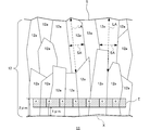
- FIG. 2 is a schematic cross-sectional view of the sliding member 1.
- an axial vertical cross section of the sliding member 1 is shown.
- An overlay 12 is formed on the lining 11, and a boundary X (broken line) between the lining 11 and the overlay 12 is straight.
- the boundary line X is in the form of a circular arc, but a region sufficiently smaller than the curvature of the sliding member 1 is illustrated, and the boundary line X is regarded as a straight line.
- the boundary line X is a line on the interface between the lining 11 and the overlay 12.
- the range be the evaluation range E.
- the length in the width direction of the evaluation range E is 9 ⁇ m.
- the crystal grains 12 a of the overlay 12 have a columnar shape substantially perpendicular to the boundary X with the lining 11.
- the line segment with the largest length is taken as the major axis LA, and is orthogonal to the major axis LA at the midpoint of the major axis LA.
- the line segment on the crystal grain 12a is taken as the minor axis SA.
- an average value of ratios obtained by dividing the length of the major axis LA of each crystal grain 12a by the minor axis SA is defined as an average aspect ratio.
- the average aspect ratio of the crystal grains 12a was 3.
- the direction of the major axis LA (direction approaching the sliding surface S) in each crystal grain 12a is taken as the crystal growth direction
- the arithmetic mean value in the crystal growth direction in each crystal grain 12a is taken as the average crystal growth direction.
- the average crystal growth direction in the present embodiment was substantially perpendicular (85 degrees) to the sliding surface S.
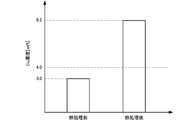
- FIG. 3 is a graph showing the average concentration of Cu in the evaluation range E.
- Cu contained in the overlay 12 is a diffusion component from the lining 11.
- the average concentration of Cu in the evaluation range E was 3.0 wt% before the heat treatment described later
- the average concentration of Cu in the evaluation range E after the heat treatment described later was 8.2 wt%.
- the evaluation range E originally Cu of the lining 11 is diffused by 3.0 wt%, but the concentration of Cu increases by 5.2 wt% by performing the heat treatment.
- the concentration of Cu as a diffusion component from the lining 11 decreases with distance from the interface with the lining 11.
- Sn contained in the lining 11 is also diffused in the overlay 12 like Cu.
- the concentration of Cu was measured for each divided range e obtained by dividing the evaluation range E in the direction of the boundary line X, and the standard deviation of the concentration of Cu for each divided range e was calculated. As a result, the standard deviation of the concentration of Cu for each division range e was 5.6 wt%.
- the width of the division range e in the direction of the boundary line X is the same as the average width of the Bi crystal grains in the direction of the boundary line X.
- the average width of crystal grains of Bi is an arithmetic average value of the length of the minor axis SA of each crystal grain 12a.
- FIG. 4 is a cross-sectional photograph of the sliding member 1.
- a protruding portion P in which the concentration of Cu is high on the side of the overlay 12 relative to the boundary line X is present.
- the protruding portion P is considered to be a portion exposed in the cross section of FIG. 4 among the grain boundaries of the crystal grains 12 a. That is, in the overlay 12, Cu is diffused at a concentration higher than that in the crystal grain 12a in the grain boundary of the crystal grain 12a, and a portion where the grain boundary of the crystal grain 12a is exposed in the cross section of FIG. It will appear as a protrusion P.
- the standard deviation of the concentration of Cu in each divided range e obtained by dividing the evaluation range E in the direction of the boundary X is as large as 5.6 wt%.
- the diffusion component from the lining 11 diffuses into the overlay 12 to improve the wear resistance.
- the wear resistance can be easily improved by diffusing Cu as a hard material from the lining 11 as a base layer into the overlay 12 as a covering layer.
- the wear progresses to the evaluation range E at the latest Good abrasion resistance can be exhibited at the stage of The inventor controls the average concentration of the diffusion component in the evaluation range E in which the distance from the interface between the lining 11 and the overlay 12 is 1 ⁇ m or more and 2 ⁇ m or less to be 4 wt% or more. It was confirmed that the wear resistance was improved more than when the concentration was less than 4 wt%.
- the diffusion component from the lining 11 is diffused to the overlay 12 by grain boundary diffusion.
- This strengthens the portion of the sliding surface S where the grain boundary of the crystal grain 12a of the overlay 12 is exposed, while the portion (within the grain) other than the grain boundary of the crystal grain 12a of the crystal grain 12a is exposed Can maintain flexibility. Therefore, both wear resistance and conformability can be achieved.
- the standard deviation of the concentration of the diffusion component in the direction parallel to the interface between the lining 11 and the overlay 12 is 5.6 wt%, which is 3 wt% or more.
- the standard deviation of the concentration of the diffusion component in the direction parallel to the interface is 3 wt% or more, it is determined that the diffusion component is diffused by being biased to the grain boundary among the grain boundary and the inside of the grain. it can.
- the present inventor controls the standard deviation of the concentration of the diffusion component to less than 3 wt% It was confirmed that the familiarity would be better than in the case.
- each layer was measured by the following procedure. First, the vertical cross section of the sliding member 1 in the axial direction was polished with a cross section polisher (IB-09010 CP, manufactured by Nippon Denshi K.K.). Then, the cross section of the sliding member 1 was photographed with an electron microscope (JSM-6610A manufactured by JEOL) at a magnification of 7,000 times to obtain image data of an observation image (reflected electron image). Then, the film thickness was measured by analyzing the observation image with an image analyzer (Lusex AP manufactured by Nireco).
- IB-09010 CP manufactured by Nippon Denshi K.K.
- an analysis image was obtained by photographing the cross section of the sliding member 1 with an electron microscope (JSM-6610A manufactured by JEOL Ltd.) at a magnification of 15000 ⁇ . Then, the analysis image was analyzed by an image analyzer (Lusex AP manufactured by Nireco). Specifically, the average line (JIS B 0601) of the waviness curves forming the interface between the lining 11 and the overlay 12 was specified as the boundary line X by the image analysis device. Furthermore, the grain boundary of each crystal grain 12a in the overlay 12 was detected by the image analysis device, and the major axis LA, the minor axis SA, and the crystal growth direction of each crystal grain 12a were specified.
- each crystal grain 12a can be detected by edge detection, for example. Furthermore, an average value of ratios obtained by dividing the length of the major axis LA of each crystal grain 12a by the minor axis SA was calculated as an average aspect ratio. The crystal grains 12 a having an equivalent circle diameter of less than 0.1 ⁇ m were excluded from the calculation targets of the aspect ratio.
- concentration of Cu in the evaluation range E of FIG. 2 was measured as follows. Specifically, the evaluation range E is obtained by analyzing the cross section of the sliding member 1 polished by the cross section polisher described above using an elemental analyzer (EDS (energy dispersive X-ray spectrometer) of JSM-6610A manufactured by JEOL Ltd.). The concentration of Cu was measured.
- EDS energy dispersive X-ray spectrometer
- (1-3) Manufacturing Method of Sliding Member First, a flat plate of low carbon steel having the same thickness as the backing metal 10 was prepared. Next, the powder of the material which comprises lining 11 was spread on the plane board formed with low carbon steel. Specifically, Cu powder, Bi powder, and Sn powder were dispersed on a flat plate of low carbon steel so that the mass ratio of each component in the lining 11 described above was obtained. As long as the mass ratio of each component in the lining 11 can be satisfied, an alloy powder such as Cu—Bi, Cu—Sn may be dispersed on a flat plate of low carbon steel. The particle size of the powder was adjusted to 150 ⁇ m or less by a test sieve (JIS Z8801).
- the sintering temperature was controlled to 700 to 1000 ° C., and sintering was performed in an inert atmosphere. After sintering, it cooled.
- the lining 11 may not necessarily be formed by sintering, and may be formed by casting or the like.
- a Cu alloy layer is formed on a flat plate of low carbon steel.
- the Cu alloy layer contains soft Bi particles precipitated during cooling.
- the low carbon steel on which the Cu alloy layer was formed was pressed so that the hollow cylinder had a shape obtained by dividing the diameter into two equal parts. At this time, pressing was performed so that the outer diameter of the low carbon steel matched the outer diameter of the sliding member 1.
- the surface of the Cu alloy layer formed on the back metal 10 was cut.
- the cutting amount was controlled so that the thickness of the Cu alloy layer formed on the back metal 10 was the same as that of the lining 11.
- the lining 11 can be formed by the Cu alloy layer after cutting.
- the cutting process was performed by, for example, a lathe in which a cutting tool material formed of sintered diamond was set.
- the surface of the lining 11 after cutting forms an interface between the lining 11 and the overlay 12.
- an overlay 12 was formed by laminating Bi to a thickness of 10 ⁇ m by electroplating on the surface of the lining 11.
- the procedure of electroplating was as follows. First, the surface of the lining 11 was washed with water. Furthermore, by pickling the surface of the lining 11, unnecessary oxide was removed from the surface of the lining 11. Thereafter, the surface of the lining 11 was washed again with water.
- electroplating was performed by supplying a current to the lining 11 immersed in the plating bath. It was set as the bath composition of the plating bath which contains methanesulfonic acid: 50-250 g / l, methanesulfonic acid Bi: 5-40 g / l (Bi concentration), surfactant: 0.5-50 g / l.
- the bath temperature of the plating bath was 20 to 50.degree.
- the current supplied to the lining 11 is a direct current, and the current density is 0.5 to 7.5 A / dm 2 .
- the plating bath (liquid) was kept stationary without liquid flow. Thereby, crystal grains 12 a can be crystal-grown from the surface of the lining 11 toward the center of curvature. After completion of the electroplating, water washing and drying were performed.
- the components of the lining 11 (mainly Cu) were diffused into the overlay 12 by heat treatment for 50 hours while maintaining 150 ° C.
- the heat treatment temperature is preferably 65% or less of the melting point of the element to be diffused, and is preferably 175 ° C. or less when the element to be diffused is Bi.
- the component of the lining 11 can be prevented from diffusing into the Bi crystal grains 12 a, and the component of the lining 11 can be diffused to the grain boundaries of the Bi crystal grains 12 a.
- the sliding bearing A is formed by combining the two sliding members 1 in a cylindrical shape.
- the sliding member 1 which comprises the sliding bearing A which bears the crankshaft of an engine was illustrated, you may form the sliding bearing A of another use by the sliding member 1 of this invention.
- the sliding member 1 of the present invention may form a radial bearing such as a gear bushing for a transmission or a piston pin bushing or boss bushing.
- the sliding member of the present invention may be a thrust bearing, may be various washers, or may be a swash plate for a car air conditioner compressor.
- the matrix of the lining 11 is not limited to the Cu alloy, and the material of the matrix may be selected according to the hardness of the mating shaft 2.
- the material of the covering layer may be any material that is softer than the lining 11, and may be, for example, any of Pb, Sn, In, and Sb.
Landscapes
- Engineering & Computer Science (AREA)
- General Engineering & Computer Science (AREA)
- Mechanical Engineering (AREA)
- Chemical & Material Sciences (AREA)
- Materials Engineering (AREA)
- Metallurgy (AREA)
- Organic Chemistry (AREA)
- Chemical Kinetics & Catalysis (AREA)
- Sliding-Contact Bearings (AREA)
Abstract
【課題】簡易な構成により良好な耐摩耗性を実現できる技術を提供する。 【解決手段】摺動部材およびすべり軸受は、基層上に、相手材との摺動面を有する被覆層が形成された摺動部材およびすべり軸受であって、前記基層は、前記被覆層よりも硬い硬質材料で形成され、前記被覆層のうち、前記基層との界面からの距離が1μm以上かつ2μm以下の評価範囲において、前記基層から拡散した前記硬質材料の拡散成分の平均濃度が4wt%以上となる。
Description
本発明は、摺動面にて相手材が摺動する摺動部材およびすべり軸受に関する。
0.3~25容量%の無機物粒子をめっき被膜中に分散させたすべり軸受が知られている(特許文献1、参照。)。特許文献1において、めっき被膜中に含まれる無機物粒子によって耐摩耗性を向上させることができる。
しかしながら、特許文献1のように、めっき被膜中に無機物粒子を分散させることは技術的に困難であるという問題があった。具体的に、めっきの際に、無機物粒子の凝集が生じるとともに、共析率をコントロールすることが困難であるという問題があった。その結果、めっき被膜中における無機物粒子の分散状態を安定してコントロールできず、良好な耐摩耗性を実現することができなかった。
本発明は、前記課題にかんがみてなされたもので、簡易な構成により良好な耐摩耗性を実現できる技術を提供することを目的とする。
本発明は、前記課題にかんがみてなされたもので、簡易な構成により良好な耐摩耗性を実現できる技術を提供することを目的とする。
前記の目的を達成するため、本発明の摺動部材およびすべり軸受は、基層上に、相手材との摺動面を有する被覆層が形成された摺動部材およびすべり軸受であって、基層は、被覆層よりも硬い硬質材料で形成され、被覆層のうち、基層との界面からの距離が1μm以上かつ2μm以下の評価範囲において、基層から拡散した硬質材料の拡散成分の平均濃度が4wt%以上となる。
前記の構成において、被覆層は基層の硬質材料よりも軟らかい材料で形成されるが、基層からの拡散成分が被覆層中に拡散することにより、耐摩耗性を向上させることができる。また、硬質材料を基層から被覆層中に拡散させることにより、容易に耐摩耗性を向上させることができる。硬質材料を基層から被覆層中に拡散させることにより、基層から遠い被覆層の表面側を軟らかい状態で維持することができ、良好な初期なじみ性を得ることができる。また、基層との界面からの距離が1μm以上かつ2μm以下の評価範囲における拡散成分の平均濃度を4wt%以上とすることにより、遅くとも評価範囲まで摩耗が進行した段階で良好な耐摩耗性を発揮できる。また、評価範囲における拡散成分の平均濃度を8.2wt%以上とするのがより望ましい。
ここで、被覆層は、Bi,Sn,Pb,InまたはSbで形成されてもよい。Bi,Sn,Pb,In,Sbは、いずれも硬度(例えばモース硬度)が小さく、基層の硬質材料よりも軟らかい材料として好適である。一方、基層の硬質材料は、これらの被覆層の材料よりも硬い材料であればよく、これらの被覆層中に拡散可能な材料であればよい。基層は、単一元素の金属で形成されてもよいし、合金で形成されてもよいし、マトリクス中に各種粒子が分散した材料で形成されてもよい。
また、基層からの拡散成分は、少なくとも被覆層の結晶粒界における粒界拡散によって被覆層に拡散してもよい。これにより、摺動面のうち被覆層の結晶粒の粒界が露出した部分を強化する一方で、被覆層の結晶粒の粒界以外の部分(粒内)が露出した部分においては柔軟性を維持することができる。従って、耐摩耗性となじみ性とを両立させることができる。なお、拡散成分は、少なくとも粒界拡散によって拡散した成分を含めばよく、粒内拡散の成分と粒界拡散の成分とが含まれてもよい。
さらに、評価範囲において、界面に平行な方向における拡散成分の濃度の標準偏差が3wt%以上であってもよい。このように、基層と被覆層との界面に平行な方向における拡散成分の濃度の標準偏差が3wt%以上となる場合に、粒界に偏って拡散成分が拡散していると判断することができる。
ここでは、下記の順序に従って本発明の実施の形態について説明する。
(1)第1実施形態:
(1-1)摺動部材の構成:
(1-2)計測方法:
(1-3)摺動部材の製造方法:
(2)他の実施形態:
(1)第1実施形態:
(1-1)摺動部材の構成:
(1-2)計測方法:
(1-3)摺動部材の製造方法:
(2)他の実施形態:
(1)第1実施形態:
(1-1)摺動部材の構成:
図1は、本発明の一実施形態にかかる摺動部材1の斜視図である。摺動部材1は、裏金10とライニング11とオーバーレイ12とを含む。摺動部材1は、中空状の円筒を直径方向に2等分した半割形状の金属部材であり、断面が半円弧状となっている。2個の摺動部材1を円筒状になるように組み合わせることにより、すべり軸受Aが形成される。すべり軸受Aは内部に形成される中空部分にて円柱状の相手軸2(エンジンのクランクシャフト)を軸受けする。相手軸2の外径はすべり軸受Aの内径よりもわずかに小さく形成されている。相手軸2の外周面と、すべり軸受Aの内周面との間に形成される隙間に潤滑油(エンジンオイル)が供給される。その際に、すべり軸受Aの内周面上を相手軸2の外周面が摺動する。
(1-1)摺動部材の構成:
図1は、本発明の一実施形態にかかる摺動部材1の斜視図である。摺動部材1は、裏金10とライニング11とオーバーレイ12とを含む。摺動部材1は、中空状の円筒を直径方向に2等分した半割形状の金属部材であり、断面が半円弧状となっている。2個の摺動部材1を円筒状になるように組み合わせることにより、すべり軸受Aが形成される。すべり軸受Aは内部に形成される中空部分にて円柱状の相手軸2(エンジンのクランクシャフト)を軸受けする。相手軸2の外径はすべり軸受Aの内径よりもわずかに小さく形成されている。相手軸2の外周面と、すべり軸受Aの内周面との間に形成される隙間に潤滑油(エンジンオイル)が供給される。その際に、すべり軸受Aの内周面上を相手軸2の外周面が摺動する。
摺動部材1は、曲率中心から遠い順に、裏金10とライニング11とオーバーレイ12とが順に積層された構造を有する。従って、裏金10が摺動部材1の最外層を構成し、オーバーレイ12が摺動部材1の最内層を構成する。裏金10とライニング11とオーバーレイ12とは、それぞれ円周方向において一定の厚みを有している。裏金10の厚みは1.8mmであり、ライニング11の厚みは0.2mmであり、オーバーレイ12の厚みは10μmである。オーバーレイ12の曲率中心側の表面の直径(摺動部材1の内径)73mmである。以下、内側とは摺動部材1の曲率中心側を意味し、外側とは摺動部材1の曲率中心と反対側を意味することとする。オーバーレイ12の内側の表面は、相手軸2の摺動面を構成する。
裏金10は、Cを0.15wt%含有し、Mnを0.06wt%含有し、残部がFeからなる鋼で形成されている。なお、裏金10は、ライニング11とオーバーレイ12とを介して相手軸2からの荷重を支持できる材料で形成されればよく、必ずしも鋼で形成されなくてもよい。
ライニング11は、裏金10の内側に積層された層であり、本発明の基層を構成する。ライニング11は、Snを10wt%含有し、Biを8wt%含有し、残部がCuと不可避不純物とからなる。ライニング11の不可避不純物はMg,Ti,B,Pb,Cr等であり、精錬もしくはスクラップにおいて混入する不純物である。不可避不純物の含有量は、全体で1.0wt%以下である。
オーバーレイ12は、ライニング11の内側の表面上に積層された層であり、本発明の被覆層を構成する。オーバーレイ12は、Biとライニング11からの拡散成分と不可避不純物とからなり、不可避不純物の含有量は1.0wt%以下である。
図2は、摺動部材1の断面模式図である。同図において、摺動部材1の軸方向の垂直断面が示されている。ライニング11上にオーバーレイ12が形成されており、ライニング11とオーバーレイ12との境界線X(破線)が直線状となっている。厳密には境界線Xは円弧状となるが、摺動部材1の曲率に対して十分に小さい領域を図示しており、境界線Xを直線と見なしている。境界線Xは、ライニング11とオーバーレイ12との界面上の線である。図2において、オーバーレイ12のうち、境界線Xを1μmだけ摺動面S側に平行移動させた線と、当該境界線Xを2μmだけ摺動面S側に平行移動させた線によって挟まれた範囲を評価範囲Eとする。本実施形態では、評価範囲Eの幅方向の長さを9μmとした。
図2に示すように、オーバーレイ12の結晶粒12aは、ライニング11との境界線Xに対してほぼ垂直な柱状の形状を有している。単一の結晶粒12aの輪郭線上の2点を接続する線分のうち、長さが最大となる線分を長軸LAとし、当該長軸LAの中点にて当該長軸LAに直交する結晶粒12a上の線分を短軸SAとする。また、各結晶粒12aにおける長軸LAの長さを短軸SAで除算した比の平均値を平均アスペクト比とする。結晶粒12aの平均アスペクト比は3であった。さらに、各結晶粒12aにおける長軸LAの方向(摺動面Sに近づく方向)を結晶成長方向とし、各結晶粒12aにおける結晶成長方向の算術平均値を平均結晶成長方向とする。本実施形態における平均結晶成長方向は、摺動面Sに対してほぼ垂直(85度)であった。
図3は、評価範囲EにおけるCuの平均濃度を示すグラフである。オーバーレイ12に含まれるCuは、ライニング11からの拡散成分である。図3に示すように、後述する熱処理を行う前では評価範囲EにおけるCuの平均濃度が3.0wt%であったのに対し、後述する熱処理を行った後では評価範囲EにおけるCuの平均濃度が8.2wt%となった。評価範囲Eにおいては、もともとライニング11のCuが3.0wt%だけ拡散しているが、熱処理を行うことにより、Cuの濃度が5.2wt%増加する。
オーバーレイ12において、ライニング11との界面から遠くなるほど、ライニング11からの拡散成分としてのCuの濃度が小さくなる。なお、ライニング11に含まれるSnもCuと同様にオーバーレイ12内に拡散している。
図2において、評価範囲Eを境界線Xの方向に分割した分割範囲eごとにCuの濃度を計測し、分割範囲eごとのCuの濃度の標準偏差を算出した。その結果、分割範囲eごとのCuの濃度の標準偏差は、5.6wt%であった。境界線Xの方向における分割範囲eの幅は、境界線Xの方向におけるBiの結晶粒の平均幅と同じである。Biの結晶粒の平均幅は、各結晶粒12aの短軸SAの長さの算術平均値である。
図4は、摺動部材1の断面写真である。同図において、色(グレー)が濃いほど、Cuの濃度が高いことを意味する。同図に示すように、境界線Xよりもオーバーレイ12側においてCuの濃度が高濃度となっている突出部Pが存在している。この突出部Pは、結晶粒12aの粒界のうち、図4の断面に露出している部分であると考えられる。つまり、オーバーレイ12において、結晶粒12aの粒界において結晶粒12aの粒内よりも高濃度でCuが拡散しており、図4の断面のうち結晶粒12aの粒界が露出している部分が突出部Pとして表れることとなる。このことは、評価範囲Eを境界線Xの方向に分割した分割範囲eごとのCuの濃度の標準偏差が5.6wt%と大きいことによっても裏付けられる。
以上説明した本実施形態において、ライニング11からの拡散成分がオーバーレイ12中に拡散することにより、耐摩耗性を向上させることができる。また、硬質材料としてのCuを基層としてのライニング11から被覆層としてのオーバーレイ12中に拡散させることにより、容易に耐摩耗性を向上させることができる。Cuをオーバーレイ12中に拡散させることにより、ライニング11から遠いオーバーレイ12の表面側を軟らかい状態で維持することができ、良好な初期なじみを得ることができる。また、ライニング11とオーバーレイ12との界面からの距離が1μm以上かつ2μm以下の評価範囲Eにおける拡散成分(Cu)の平均濃度を8.2wt%とすることにより、遅くとも評価範囲Eまで摩耗が進行した段階で良好な耐摩耗性を発揮できる。本発明者は、ライニング11とオーバーレイ12との界面からの距離が1μm以上かつ2μm以下の評価範囲Eにおける拡散成分の平均濃度を4wt%以上となるように管理することにより、当該拡散成分の平均濃度が4wt%未満である場合よりも耐摩耗性が向上することを確認した。
また、ライニング11からの拡散成分は、粒界拡散によってオーバーレイ12に拡散している。これにより、摺動面Sのうちオーバーレイ12の結晶粒12aの粒界が露出した部分を強化する一方で、結晶粒12aの結晶粒12aの粒界以外の部分(粒内)が露出した部分においては柔軟性を維持することができる。従って、耐摩耗性となじみ性とを両立させることができる。さらに、評価範囲Eにおいて、ライニング11とオーバーレイ12との界面に平行な方向における拡散成分の濃度の標準偏差が3wt%以上の5.6wt%となる。このように、界面に平行な方向における拡散成分の濃度の標準偏差が3wt%以上となる場合に、粒界と粒内のうち粒界に偏って拡散成分が拡散していると判断することができる。本発明者は、ライニング11とオーバーレイ12との界面に平行な方向における拡散成分の濃度の標準偏差が3wt%以上となるように管理することにより、当該拡散成分の濃度の標準偏差が3wt%未満である場合よりもなじみ性が向上することを確認した。
(1-2)計測方法:
上述した実施形態において示した各数値を以下の手法によって計測した。摺動部材1の各層を構成する元素の質量は、ICP発光分光分析装置(島津社製ICPS-8100)によって計測した。
上述した実施形態において示した各数値を以下の手法によって計測した。摺動部材1の各層を構成する元素の質量は、ICP発光分光分析装置(島津社製ICPS-8100)によって計測した。
各層の厚みは、以下の手順で計測した。まず、摺動部材1の軸方向の垂直断面をクロスセクションポリッシャ(日本電子製 IB-09010CP)で研磨した。そして、摺動部材1の断面を電子顕微鏡(日本電子製 JSM-6610A)によって7000倍の倍率で撮影することにより、観察画像(反射電子像)の画像データを得た。そして、観察画像を画像解析装置(ニレコ社製 ルーゼックス AP)によって解析することにより膜厚を計測した。
さらに、摺動部材1の断面を電子顕微鏡(日本電子製 JSM-6610A)によって15000倍の倍率で撮影することにより解析画像を得た。そして、解析画像を画像解析装置(ニレコ社製 ルーゼックス AP)によって解析した。具体的に、画像解析装置によって、ライニング11とオーバーレイ12との界面をなすうねり曲線の平均線(JIS B 0601)を境界線Xとして特定した。さらに、画像解析装置によって、オーバーレイ12における各結晶粒12aの粒界を検出し、各結晶粒12aの長軸LAと短軸SAと結晶成長方向とを特定した。各結晶粒12aの粒界は、例えばエッジ検出によって検出できる。さらに、各結晶粒12aにおける長軸LAの長さを短軸SAで除算した比の平均値を平均アスペクト比として算出した。なお、円相当径が0.1μm未満となる結晶粒12aについては、アスペクト比の算出対象から除外した。
また、図2の評価範囲EにおけるCuの濃度を以下のように計測した。具体的に、上述したクロスセクションポリッシャで研磨した摺動部材1の断面を元素分析装置(日本電子製 JSM-6610AのEDS(エネルギー分散型X線分光器))によって分析することにより、評価範囲EにおけるCuの濃度を計測した。
(1-3)摺動部材の製造方法:
まず、裏金10と同じ厚みを有する低炭素鋼の平面板を用意した。
次に、低炭素鋼で形成された平面板上に、ライニング11を構成する材料の粉末を散布した。具体的に、上述したライニング11における各成分の質量比となるように、Cuの粉末とBiの粉末とSnの粉末とを低炭素鋼の平面板上に散布した。ライニング11における各成分の質量比が満足できればよく、Cu-Bi,Cu-Sn等の合金粉末を低炭素鋼の平面板上に散布してもよい。粉末の粒径は、試験用ふるい(JIS Z8801)によって150μm以下に調整した。
まず、裏金10と同じ厚みを有する低炭素鋼の平面板を用意した。
次に、低炭素鋼で形成された平面板上に、ライニング11を構成する材料の粉末を散布した。具体的に、上述したライニング11における各成分の質量比となるように、Cuの粉末とBiの粉末とSnの粉末とを低炭素鋼の平面板上に散布した。ライニング11における各成分の質量比が満足できればよく、Cu-Bi,Cu-Sn等の合金粉末を低炭素鋼の平面板上に散布してもよい。粉末の粒径は、試験用ふるい(JIS Z8801)によって150μm以下に調整した。
次に、低炭素鋼の平面板と、当該平面板上に散布した粉末とを焼結した。焼結温度を700~1000℃に制御し、不活性雰囲気中で焼結した。焼結後、冷却した。なお、ライニング11は必ずしも焼結によって形成されなくてもよく、鋳造等によって形成されてもよい。
冷却が完了すると、低炭素鋼の平面板上にCu合金層が形成される。このCu合金層には、冷却中に析出した軟質のBi粒子が含まれることとなる。
次に、中空状の円筒を直径で2等分した形状となるように、Cu合金層が形成された低炭素鋼をプレス加工した。このとき、低炭素鋼の外径が摺動部材1の外径と一致するようにプレス加工した。
次に、中空状の円筒を直径で2等分した形状となるように、Cu合金層が形成された低炭素鋼をプレス加工した。このとき、低炭素鋼の外径が摺動部材1の外径と一致するようにプレス加工した。
次に、裏金10上に形成されたCu合金層の表面を切削加工した。このとき、裏金10上に形成されたCu合金層の厚みがライニング11と同一となるように、切削量を制御した。これにより、切削加工後のCu合金層によってライニング11が形成できる。切削加工は、例えば焼結ダイヤモンドで形成された切削工具材をセットした旋盤によって行った。切削加工後のライニング11の表面は、ライニング11とオーバーレイ12との界面を構成する。
次に、ライニング11の表面上にBiを電気めっきによって10μmの厚みだけ積層することにより、オーバーレイ12を形成した。電気めっきの手順は以下のとおりとした。まず、ライニング11の表面を水洗した。さらに、ライニング11の表面を酸洗することにより、ライニング11の表面から不要な酸化物を除去した。その後、ライニング11の表面を、再度、水洗した。
以上の前処理が完了すると、めっき浴に浸漬させたライニング11に電流を供給することにより電気めっきを行った。メタンスルホン酸:50~250g/l、メタンスルホン酸Bi:5~40g/l(Bi濃度)、界面活性剤:0.5~50g/lとを含むめっき浴の浴組成とした。めっき浴の浴温度は、20~50℃とした。さらに、ライニング11に供給する電流は直流電流とし、その電流密度は0.5~7.5A/dm2とした。電気めっきにおいて、めっき浴(液)を液流のない静止状態とした。これにより、ライニング11の表面から曲率中心に向けて結晶粒12aを結晶成長させることができる。電気めっきの完了後に、水洗と乾燥を行った。
次に、150℃を維持した状態で50時間にわたって熱処理することにより、ライニング11の成分(おもにCu)をオーバーレイ12中に拡散させた。これにより、図3のグラフで示すように、評価範囲Eにおけるライニング11からの拡散成分の濃度を熱処理後において増加させることができた。熱処理の温度は、被拡散元素の融点の65%以下の温度であることが望ましく、被拡散元素がBiである場合には175℃以下であることが望ましい。これにより、Biの結晶粒12a内にライニング11の成分が拡散することを防止し、Biの結晶粒12aの粒界にライニング11の成分を拡散させることができる。
以上のようにして、摺動部材1を完成させると、2個の摺動部材1を円筒状に組み合わせることにより、すべり軸受Aを形成した。
(2)他の実施形態:
前記実施形態においては、エンジンのクランクシャフトを軸受けするすべり軸受Aを構成する摺動部材1を例示したが、本発明の摺動部材1によって他の用途のすべり軸受Aを形成してもよい。例えば、本発明の摺動部材1によってトランスミッション用のギヤブシュやピストンピンブシュ・ボスブシュ等のラジアル軸受を形成してもよい。さらに、本発明の摺動部材は、スラスト軸受であってもよく、各種ワッシャであってもよいし、カーエアコンコンプレッサ用の斜板であってもよい。また、ライニング11のマトリクスはCu合金に限られず、相手軸2の硬さに応じてマトリクスの材料が選択されればよい。また、被覆層の材料はライニング11よりも軟らかい材料であればよく、例えばPb,Sn,In,Sbのいずれかであってもよい。
前記実施形態においては、エンジンのクランクシャフトを軸受けするすべり軸受Aを構成する摺動部材1を例示したが、本発明の摺動部材1によって他の用途のすべり軸受Aを形成してもよい。例えば、本発明の摺動部材1によってトランスミッション用のギヤブシュやピストンピンブシュ・ボスブシュ等のラジアル軸受を形成してもよい。さらに、本発明の摺動部材は、スラスト軸受であってもよく、各種ワッシャであってもよいし、カーエアコンコンプレッサ用の斜板であってもよい。また、ライニング11のマトリクスはCu合金に限られず、相手軸2の硬さに応じてマトリクスの材料が選択されればよい。また、被覆層の材料はライニング11よりも軟らかい材料であればよく、例えばPb,Sn,In,Sbのいずれかであってもよい。
1…摺動部材、2…相手軸、10…裏金、11…ライニング、12…オーバーレイ、12a…結晶粒、A…軸受、E…評価範囲、LA…長軸、P…突出部、S…摺動面、SA…短軸、X…境界線、e…分割範囲
Claims (6)
- 基層上に、相手材との摺動面を有する被覆層が形成された摺動部材であって、
前記基層は、前記被覆層よりも硬い硬質材料で形成され、
前記被覆層のうち、前記基層との界面からの距離が1μm以上かつ2μm以下の評価範囲において、前記基層から拡散した前記硬質材料の拡散成分の平均濃度が4wt%以上となる、
摺動部材。 - 前記拡散成分は、少なくとも前記被覆層の結晶粒界における粒界拡散によって前記被覆層に拡散している、
請求項1に記載の摺動部材。 - 前記被覆層において、前記界面に平行な方向における前記拡散成分の濃度の標準偏差が3wt%以上となる、
請求項2に記載の摺動部材。 - 基層上に、相手材との摺動面を有する被覆層が形成されたすべり軸受であって、
前記基層は、前記被覆層よりも硬い硬質材料で形成され、
前記被覆層のうち、前記基層との界面からの距離が1μm以上かつ2μm以下の評価範囲において、前記基層から拡散した前記硬質材料の拡散成分の平均濃度が4wt%以上となる、
すべり軸受。 - 前記拡散成分は、少なくとも前記被覆層の結晶粒界における粒界拡散によって前記被覆層に拡散している、
請求項4に記載のすべり軸受。 - 前記被覆層において、前記界面に平行な方向における前記拡散成分の濃度の標準偏差が3wt%以上となる、
請求項5に記載のすべり軸受。
Priority Applications (3)
| Application Number | Priority Date | Filing Date | Title |
|---|---|---|---|
| CN201880002171.4A CN109429498B (zh) | 2017-06-21 | 2018-05-28 | 滑动构件以及滑动轴承 |
| DE112018000070.2T DE112018000070T5 (de) | 2017-06-21 | 2018-05-28 | Gleitelement und gleitlager |
| US16/325,546 US20230160425A1 (en) | 2017-06-21 | 2018-05-28 | Sliding member and sliding bearing |
Applications Claiming Priority (2)
| Application Number | Priority Date | Filing Date | Title |
|---|---|---|---|
| JP2017-121114 | 2017-06-21 | ||
| JP2017121114A JP6777594B2 (ja) | 2017-06-21 | 2017-06-21 | 摺動部材およびすべり軸受 |
Publications (1)
| Publication Number | Publication Date |
|---|---|
| WO2018235529A1 true WO2018235529A1 (ja) | 2018-12-27 |
Family
ID=64735739
Family Applications (1)
| Application Number | Title | Priority Date | Filing Date |
|---|---|---|---|
| PCT/JP2018/020347 Ceased WO2018235529A1 (ja) | 2017-06-21 | 2018-05-28 | 摺動部材およびすべり軸受 |
Country Status (5)
| Country | Link |
|---|---|
| US (1) | US20230160425A1 (ja) |
| JP (1) | JP6777594B2 (ja) |
| CN (1) | CN109429498B (ja) |
| DE (1) | DE112018000070T5 (ja) |
| WO (1) | WO2018235529A1 (ja) |
Families Citing this family (2)
| Publication number | Priority date | Publication date | Assignee | Title |
|---|---|---|---|---|
| CA3149276A1 (en) * | 2019-10-23 | 2021-04-29 | Karapet Ablabutyan | Torsion bar bracket with bushing |
| JP7656392B2 (ja) * | 2020-12-09 | 2025-04-03 | 大同メタル工業株式会社 | 摺動部材及びその製造方法 |
Citations (5)
| Publication number | Priority date | Publication date | Assignee | Title |
|---|---|---|---|---|
| JP2000017418A (ja) * | 1998-06-29 | 2000-01-18 | Toshiba Corp | 軸受部品の製造方法 |
| JP2007501919A (ja) * | 2003-08-12 | 2007-02-01 | フエデラル―モーグル・ウイースバーデン・ゲゼルシヤフト・ミト・ベシユレンクテル・ハフツング | 軸受け用積層複合体材料、その製造および用途 |
| JP2008057769A (ja) * | 2006-06-09 | 2008-03-13 | Miba Gleitlager Gmbh | 多層軸受 |
| JP2009264439A (ja) * | 2008-04-23 | 2009-11-12 | Daido Metal Co Ltd | 半割軸受 |
| WO2014157193A1 (ja) * | 2013-03-29 | 2014-10-02 | 大豊工業株式会社 | 摺動部材およびすべり軸受 |
Family Cites Families (8)
| Publication number | Priority date | Publication date | Assignee | Title |
|---|---|---|---|---|
| JP2535105B2 (ja) | 1991-04-30 | 1996-09-18 | 大同メタル工業株式会社 | 複合めっき皮膜を有するすべり軸受 |
| JPH07122158B2 (ja) * | 1992-02-28 | 1995-12-25 | 大同メタル工業株式会社 | オーバーレイを有する多層すべり軸受 |
| ATE246271T1 (de) * | 1999-04-28 | 2003-08-15 | Federal Mogul Wiesbaden Gmbh | Mehrschichtenmaterial für gleitelemente und verfahren zur herstellung |
| GB2380772B (en) * | 2001-09-10 | 2004-06-09 | Daido Metal Co | Sliding member |
| DE10337030B4 (de) * | 2003-08-12 | 2007-04-05 | Federal-Mogul Wiesbaden Gmbh & Co. Kg | Schichtverbundwerkstoff, Herstellung und Verwendung |
| CN101680482B (zh) * | 2007-03-12 | 2012-12-26 | 大丰工业株式会社 | 滑动轴承 |
| JP5981868B2 (ja) * | 2013-03-29 | 2016-08-31 | 大豊工業株式会社 | 摺動部材およびすべり軸受 |
| JP6234637B2 (ja) * | 2015-12-01 | 2017-11-22 | 大豊工業株式会社 | 摺動部材およびすべり軸受 |
-
2017
- 2017-06-21 JP JP2017121114A patent/JP6777594B2/ja active Active
-
2018
- 2018-05-28 DE DE112018000070.2T patent/DE112018000070T5/de active Pending
- 2018-05-28 CN CN201880002171.4A patent/CN109429498B/zh active Active
- 2018-05-28 US US16/325,546 patent/US20230160425A1/en not_active Abandoned
- 2018-05-28 WO PCT/JP2018/020347 patent/WO2018235529A1/ja not_active Ceased
Patent Citations (5)
| Publication number | Priority date | Publication date | Assignee | Title |
|---|---|---|---|---|
| JP2000017418A (ja) * | 1998-06-29 | 2000-01-18 | Toshiba Corp | 軸受部品の製造方法 |
| JP2007501919A (ja) * | 2003-08-12 | 2007-02-01 | フエデラル―モーグル・ウイースバーデン・ゲゼルシヤフト・ミト・ベシユレンクテル・ハフツング | 軸受け用積層複合体材料、その製造および用途 |
| JP2008057769A (ja) * | 2006-06-09 | 2008-03-13 | Miba Gleitlager Gmbh | 多層軸受 |
| JP2009264439A (ja) * | 2008-04-23 | 2009-11-12 | Daido Metal Co Ltd | 半割軸受 |
| WO2014157193A1 (ja) * | 2013-03-29 | 2014-10-02 | 大豊工業株式会社 | 摺動部材およびすべり軸受 |
Non-Patent Citations (1)
| Title |
|---|
| IWANAMI: "Iwanami Subject Book of Physics and Chemistry. 5th ed.", pages: 998-999,1106 - 1107 * |
Also Published As
| Publication number | Publication date |
|---|---|
| CN109429498A (zh) | 2019-03-05 |
| JP2019007035A (ja) | 2019-01-17 |
| US20230160425A1 (en) | 2023-05-25 |
| JP6777594B2 (ja) | 2020-10-28 |
| CN109429498B (zh) | 2021-04-20 |
| DE112018000070T5 (de) | 2019-03-14 |
Similar Documents
| Publication | Publication Date | Title |
|---|---|---|
| JP6636090B2 (ja) | 摺動部材 | |
| WO2014157193A1 (ja) | 摺動部材およびすべり軸受 | |
| US11396910B2 (en) | Sliding member and sliding bearing | |
| WO2018235529A1 (ja) | 摺動部材およびすべり軸受 | |
| US11149791B2 (en) | Sliding member | |
| JP6731969B2 (ja) | 摺動部材 | |
| JP6234637B2 (ja) | 摺動部材およびすべり軸受 | |
| JP6924315B2 (ja) | 摺動部材およびすべり軸受 | |
| JP6895338B2 (ja) | 摺動部材およびすべり軸受 | |
| JP2019100350A (ja) | 摺動部材 | |
| EP3133306A1 (en) | Sliding member and sliding bearing | |
| JP7281864B2 (ja) | 摺動部材およびすべり軸受 | |
| JP2019011493A (ja) | 摺動部材およびすべり軸受 | |
| JP7664256B2 (ja) | 摺動部材 | |
| JP6944019B2 (ja) | 摺動部材およびすべり軸受 | |
| JP6762915B2 (ja) | 摺動部材およびすべり軸受 | |
| WO2015186621A1 (ja) | 摺動部材およびすべり軸受 | |
| JP2019123914A (ja) | 摺動部材 |
Legal Events
| Date | Code | Title | Description |
|---|---|---|---|
| 121 | Ep: the epo has been informed by wipo that ep was designated in this application |
Ref document number: 18821615 Country of ref document: EP Kind code of ref document: A1 |
|
| 122 | Ep: pct application non-entry in european phase |
Ref document number: 18821615 Country of ref document: EP Kind code of ref document: A1 |