WO2018235385A1 - 端末装置およびその制御方法、ならびに制御プログラム - Google Patents
端末装置およびその制御方法、ならびに制御プログラム Download PDFInfo
- Publication number
- WO2018235385A1 WO2018235385A1 PCT/JP2018/014535 JP2018014535W WO2018235385A1 WO 2018235385 A1 WO2018235385 A1 WO 2018235385A1 JP 2018014535 W JP2018014535 W JP 2018014535W WO 2018235385 A1 WO2018235385 A1 WO 2018235385A1
- Authority
- WO
- WIPO (PCT)
- Prior art keywords
- terminal device
- pressure value
- contact
- information processing
- detected
- Prior art date
- Legal status (The legal status is an assumption and is not a legal conclusion. Google has not performed a legal analysis and makes no representation as to the accuracy of the status listed.)
- Ceased
Links
Images





Classifications
-
- G—PHYSICS
- G01—MEASURING; TESTING
- G01C—MEASURING DISTANCES, LEVELS OR BEARINGS; SURVEYING; NAVIGATION; GYROSCOPIC INSTRUMENTS; PHOTOGRAMMETRY OR VIDEOGRAMMETRY
- G01C5/00—Measuring height; Measuring distances transverse to line of sight; Levelling between separated points; Surveyors' levels
- G01C5/06—Measuring height; Measuring distances transverse to line of sight; Levelling between separated points; Surveyors' levels by using barometric means
-
- H—ELECTRICITY
- H04—ELECTRIC COMMUNICATION TECHNIQUE
- H04M—TELEPHONIC COMMUNICATION
- H04M1/00—Substation equipment, e.g. for use by subscribers
Definitions
- the present invention relates to a terminal device having a function of measuring a barometric pressure value, a control method of the terminal device, and a control program of the terminal device.
- Patent Document 1 discloses a portable electronic device for the purpose of improving the accuracy of detecting a change in air pressure.
- the portable electronic device is configured to ignore pressure fluctuation when detecting a user's operation.
- the terminal device and the like according to one aspect of the present invention has been made in view of the above problems, and its object is to measure the barometric pressure value measured when an object is in contact and pressure is applied, An object of the present invention is to realize a terminal device or the like that can appropriately process information as an atmospheric pressure value measured in a state where pressure is applied.
- a terminal unit concerning one mode of the present invention is a terminal unit which has a function which measures barometric pressure value, and the contact detection part which detects contact with the above-mentioned terminal unit and an object
- the sensor control unit includes: a sensor control unit that measures an atmospheric pressure value using an atmospheric pressure sensor; and an information processing unit that performs information processing using the measured atmospheric pressure value and outputs a result of the information processing.
- a control method of a terminal unit concerning one mode of the present invention is a control method of a terminal unit which has a function which measures barometric pressure value, and detects a contact with the above-mentioned terminal unit and object And a pressure measurement step of measuring a pressure value using a pressure sensor, and an information processing step of performing information processing using the measured pressure value and outputting the result of the information processing.
- the output form of the atmospheric pressure value measured in the atmospheric pressure measurement step is changed, and the atmospheric pressure value whose output form is changed in the information processing step is used. It is characterized in that information processing is performed.
- the measured air pressure value is used as the air pressure value measured in a state where the pressure is applied. An effect is obtained that information processing can be properly performed.
- FIGS. 1 to 10 An embodiment of the present invention will be described below with reference to FIGS. 1 to 10.
- the same symbols may be added to the other items for the components having the same functions as the components described in the certain items, and the description thereof may be omitted.
- sensors such as barometric pressure sensors basically use the concept of Always-On (always operate), and the sensors always operate even during periods when the user is not operating or displaying It is thought that the usage of continuing will increase in the future.
- a barometric pressure sensor to detect movement between floor levels in indoor navigation that does not use GPS (Global Positioning System) or record the level movement by fitness, and use the barometric pressure value to move the levels It is detected.
- GPS Global Positioning System
- the portable terminal when the portable terminal is put in the front pocket of the pants, the portable terminal may be pressed by the foot when going up the stairs, and the instantaneous pressure value may be detected as the barometric pressure value. For this reason, there is a possibility of detecting a hierarchical change which is not going up.
- the terminal device 1 described below for example, while it is possible to see or mitigate fluctuations in barometric pressure value while putting in the front pocket of the pants, it is possible to detect an erroneous hierarchy change. It is possible to use the pressure value with high accuracy.
- the terminal device 1 is a waterproof compatible terminal, and is provided with waterproof performance (airtightness) by sealing the outer peripheral portion of the housing of the terminal device 1 with a waterproof tape, rubber, an adhesive, or the like.
- the pressure value inside the case is made equal to the outside by providing a venting film described later.
- the venting membrane is a membrane that allows only air to pass through without passing moisture. By means of the venting membrane, the pressure value inside and outside the housing can be kept equal while maintaining waterproofness.
- FIG. 1 is a block diagram showing the configuration of the terminal device 1.
- the terminal device 1 is a terminal device having a function of measuring the barometric pressure value.
- the terminal device 1 includes a control unit 10, an air pressure sensor 20, a proximity sensor 40, an acceleration sensor 41, a timer 50, a storage unit 60, and a display unit 70.
- the control unit 10 controls each part of the terminal device 1 in an integrated manner. As shown in FIG. 1, the control unit 10 includes a sensor control unit 11, a contact state detection unit (contact detection unit) 12, a recording control unit 13, a display control unit 14, a reliability setting unit 15, and an information processing unit 16. Have.
- the sensor control unit 11 measures an air pressure value using the air pressure sensor 20.
- the sensor control unit 11 also controls the operation of the barometric pressure sensor 20 and the filter 30.
- the sensor control unit 11 further includes a filter 30 and a measurement value acquisition unit 111, and acquires information related to an air pressure value generated based on a detection signal of the air pressure sensor 20. Further, when the contact between the terminal device 1 and the object is detected, the sensor control unit 11 changes the output form of the barometric pressure value to the information processing unit 16.
- the sensor control unit 11 changes the coefficient of the filter 30 according to whether or not the contact between the terminal device 1 and the object is detected. Specifically, the coefficients of the filter 30 are switched to the hard mode or the normal mode.
- the filter 30 has a function of smoothing (relaxing) a change in the measured air pressure value, and is configured by, for example, an LPF (low pass filter) or the like. Switching the filter 30 to the hard mode or the normal mode is, for example, to turn the filter 30 on or off or to switch the coefficients of the filter 30 to be steep or gentle.
- LPF low pass filter
- the sensor control unit 11 When the contact between the terminal device 1 and the object is detected, the sensor control unit 11 turns on the filter 30. On the other hand, when the contact between the terminal device 1 and the object is not detected, the sensor control unit 11 turns off the filter 30.
- the barometric pressure sensor 20 measures a barometric pressure value. Also, by passing the filter 30 in order to reduce noise (excessive response value) at the time of measurement value measurement by the air pressure sensor 20, fine fluctuation of the measured air pressure value is reduced, and a relatively stable air pressure value can be obtained. It becomes possible to acquire.
- the measured value of the air pressure measured through the filter 30 is the measured value of the air pressure when the filter 30 is not applied (see the thin solid line graph).
- relatively gradual change see thick solid line graph.
- the graph shown in FIG. 5 shows the result of measuring the barometric pressure value when pressure was applied to the housing of the terminal device 1 in a pseudo manner (five times).
- the measurement of barometric pressure measured through the filter 30 is smooth without any sharp changes in the measured barometric pressure without the filter 30. However, the response is delayed with respect to the timing of the change.
- the sensor control unit 11 may replace the pressure value measured after the detection with the pressure value measured before the detection and output the pressure value. good. Thereby, it is possible to replace the incorrect air pressure value affected by the contact between the terminal device 1 and the object with the air pressure value measured without being affected by the contact between the terminal device 1 and the object Become.
- the sensor control unit 11 may output the measured atmospheric pressure value together with the reliability set lower than that before the detection. Therefore, when the contact between the terminal device 1 and the object is detected, the barometric pressure value is output together with the reliability. Therefore, it is possible to perform information processing according to the reliability on the barometric pressure value.
- the contact state detection unit 12 detects a contact between the terminal device 1 and an object. More specifically, the contact state detection unit 12 determines whether or not the contact between the terminal device 1 and the object is detected.
- the contact state detection unit 12 adopts a configuration that uses the proximity sensor 40 to determine whether an object is in contact with the terminal device 1, but the present invention is not limited to such a configuration.
- an electrostatic sensor, a touch panel or the like may be used to detect that an object is in contact with the terminal device 1. Further, the same effect can be obtained by detecting that a force is applied to the terminal device 1 using a strain sensor, a pressure sensor or the like.
- the state in which the contact is detected can be assumed to be a state in which the housing of the terminal device 1 has a possibility of being applied with any force. Conversely, it is not easy to apply physical pressure to the terminal device 1 from the outside without any object in contact with it.
- the arrangement position of the proximity sensor 40 at least one proximity sensor 40 is provided on at least one surface (for example, a display surface) of the housing of the terminal device 1. It is desirable that the surface on which the proximity sensor 40 is disposed is a surface (or a facing) that is susceptible to being pushed by the housing.
- the recording control unit 13 performs control to record the barometric pressure value acquired by the sensor control unit 11 in the storage unit 60. Further, the recording control unit 13 stores the measured barometric pressure value in the storage unit 60 in association with the measured time.
- the display control unit 14 controls the display by the display unit 70.
- the reliability setting unit 15 sets that the reliability of the measured air pressure value is low, and when the contact between the terminal device 1 and the object is not detected. Set the measured pressure value high reliability.
- the information processing unit 16 performs information processing using the barometric pressure value output from the sensor control unit 11, and outputs the result of the information processing to the display control unit 14. For example, the information processing unit 16 uses the barometric pressure value output from the sensor control unit 11 to calculate the altitude of the place where the terminal device 1 is present.
- the proximity sensor 40 and the acceleration sensor 41 are sensors for detecting contact of an object.
- the timer 50 measures the time at which the pressure value is measured, and the like.
- the storage unit 60 stores the measured barometric pressure value in association with the measured time and the like.
- the display unit 70 uses, for example, a liquid crystal panel.
- the display panel used for the display unit 70 is not limited to the liquid crystal panel, and may be an organic EL (electroluminescence) panel, an inorganic EL panel, a plasma panel or the like.
- the contact state detection unit 12 detects a contact between the terminal device 1 and an object.
- the terminal device 1 when the terminal device 1 and an object are in contact with each other, the terminal device 1 is in a state in which pressure may be applied from the outside. For this reason, it can be estimated that pressure is applied to the terminal device 1 by detecting the contact between the terminal device 1 and the object.
- the sensor control unit 11 changes the output form of the barometric pressure value to the information processing unit 16 when the contact between the terminal device 1 and the object is detected. Thereby, when the terminal device 1 and the object are in contact and pressure is applied, it is possible to set the output form of the pressure value to be measured according to the pressure applied state.
- the measured air pressure value can be properly processed as the air pressure value measured in the pressure applied state. it can.
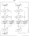
- FIG. (A) of FIG. 4 is a flowchart which shows the flow of operation
- (b) of FIG. 4 is a flow chart showing the flow of the operation when measuring the barometric pressure value continuously (when measuring the barometric pressure value continuously in the background).
- step S (hereinafter, “step” will be omitted) 101, measurement of atmospheric pressure is started, and the process proceeds to S102.
- step S102 based on the detection result of the proximity sensor 40, the contact state detection unit 12 determines whether the contact between the terminal device 1 and the object is detected. As a result, when the contact between the terminal device 1 and the object is detected, the process proceeds to S103. On the other hand, when the contact between the terminal device 1 and the object is not detected, the process proceeds to S104.
- the sensor control unit 11 switches the coefficient of the filter 30 to the hard mode, and proceeds to S105.
- the sensor control unit 11 switches the coefficient of the filter 30 to the normal mode, and proceeds to S105.
- the sensor control unit 11 measures the barometric pressure value via the proximity sensor 40 and the filter 30, and the measured value acquiring unit 111 acquires the measured value (barometric pressure value) of the detected barometric pressure, and stores it in the storage unit 60. Record and proceed to S106 to complete the pressure measurement.
- S201 measurement of atmospheric pressure is started, and the process proceeds to S202.
- the contact state detection unit 12 determines whether the contact between the terminal device 1 and the object is detected based on the detection result of the proximity sensor 40. As a result, when the contact between the terminal device 1 and the object is detected, the process proceeds to S203. On the other hand, if the contact between the terminal device 1 and the object is not detected, the process proceeds to S204.
- the sensor control unit 11 switches the coefficient of the filter 30 to the hard mode, and proceeds to S205.
- the sensor control unit 11 switches the coefficient of the filter 30 to the normal mode, and proceeds to S205.
- the sensor control unit 11 measures the barometric pressure value via the proximity sensor 40 and the filter 30, and the measured value acquiring unit 111 acquires the measured value (barometric pressure value) of the detected barometric pressure, and stores it in the storage unit 60. Record and return to S202.
- FIG. (A) of FIG. 6 is a flow chart showing the flow of the operation in the case of measuring the barometric pressure value by one shot. Further, (b) of FIG. 6 is a flow chart showing the flow of the operation when measuring the barometric pressure value continuously (when measuring the barometric pressure value continuously in the background).
- S301 measurement of a barometric pressure is started and it progresses to S302.
- the contact state detection unit 12 determines whether the contact between the terminal device 1 and the object is detected. As a result, when the contact between the terminal device 1 and the object is detected, the process proceeds to S303. On the other hand, when the contact between the terminal device 1 and the object is not detected, the process proceeds to S304.
- the sensor control unit 11 outputs the pressure value recorded last time (before detection) to the information processing unit 16 as a measurement value, and the process proceeds to S305.
- the sensor control unit 11 outputs the pressure value currently measured (after detection) to the information processing unit 16 as a measurement value, and the process proceeds to S305.
- the recording control unit 13 simultaneously stores the output pressure value in the storage area of the storage unit 60, proceeds to S306, and completes the pressure measurement.
- S401 measurement of the barometric pressure is started, and the process proceeds to S402.
- S402 based on the detection result of the proximity sensor 40, the contact state detection unit 12 determines whether the contact between the terminal device 1 and the object is detected. As a result, when the contact between the terminal device 1 and the object is detected, the process proceeds to S403. On the other hand, if the contact between the terminal device 1 and the object is not detected, the process proceeds to S404.
- the sensor control unit 11 outputs, to the information processing unit 16, an atmospheric pressure value recorded last time (before detection) as a measurement value, and the process proceeds to S405.
- the sensor control unit 11 outputs the atmospheric pressure value currently measured (after detection) to the information processing unit 16 as a measurement value, and the process proceeds to S405.
- the recording control unit 13 simultaneously stores the output air pressure value in the storage area of the storage unit 60, and returns to S402.
- FIG. (A) of FIG. 7 is a flowchart showing the flow of the operation in the case of measuring the barometric pressure value by one shot. Further, (b) of FIG. 7 is a flow chart showing a flow of operation in the case where the barometric pressure value is continuously measured (in the case where the barometric pressure value is continuously measured in the background).
- the contact state detection unit 12 determines whether the contact between the terminal device 1 and the object is detected. As a result, when the contact between the terminal device 1 and the object is detected, the process proceeds to S504. On the other hand, when the contact between the terminal device 1 and the object is not detected, the process proceeds to S505.
- the reliability setting unit 15 sets the reliability information as “low” in the barometric pressure value, and the process proceeds to S506.
- the reliability setting unit 15 sets the reliability information as "high” in the barometric pressure value, and the process proceeds to S506.
- the sensor control unit 11 outputs the air pressure value together with the information indicating the reliability to the information processing unit 16, proceeds to S507, and completes the air pressure measurement.
- S601 measurement of atmospheric pressure is started, and the process proceeds to S602.
- the sensor control unit 11 measures an air pressure value via the air pressure sensor 20, and the measurement value acquisition unit 111 acquires a measurement value of the air pressure (air pressure value), and the process proceeds to S603.
- the contact state detection unit 12 determines whether the contact between the terminal device 1 and the object is detected. As a result, when the contact between the terminal device 1 and the object is detected, the process proceeds to S604. On the other hand, when the contact between the terminal device 1 and the object is not detected, the process proceeds to S605.
- the reliability setting unit 15 sets the reliability information as “low” in the barometric pressure value, and the process proceeds to S606.
- the reliability setting unit 15 sets the reliability information as “high” in the barometric pressure value, and the process proceeds to S606.
- the sensor control unit 11 outputs the pressure value to the information processing unit 16 together with the information indicating the reliability, and the process returns to S602.
- FIG. (A) of FIG. 8 is a flow chart showing the flow of the operation in the case of measuring the barometric pressure value by one shot. Further, (b) of FIG. 8 is a flow chart showing the flow of the operation when measuring the barometric pressure value continuously (when measuring the barometric pressure value continuously in the background).
- S701 measurement of atmospheric pressure is started, and the process proceeds to S702.
- the contact state detection unit 12 determines whether the contact between the terminal device 1 and the object is detected. As a result, when the contact between the terminal device 1 and the object is detected, the process proceeds to S703. On the other hand, when the contact between the terminal device 1 and the object is not detected, the process proceeds to S705.
- the contact state detection unit 12 determines whether or not the acceleration sensor 41 has detected acceleration. As a result, if an acceleration is detected, the process proceeds to S704. On the other hand, if the acceleration is not detected, the process proceeds to S705.
- the sensor control unit 11 switches the coefficient of the filter 30 to the hard mode, and proceeds to S706.
- the sensor control unit 11 switches the coefficient of the filter 30 to the normal mode, and proceeds to S706.
- the sensor control unit 11 measures the barometric pressure value via the proximity sensor 40 and the filter 30, and the measured value acquiring unit 111 acquires a measured value (barometric pressure value) of the detected barometric pressure, and proceeds to S707. Complete the pressure measurement.
- S801 measurement of atmospheric pressure is started, and the process proceeds to S802.
- the contact state detection unit 12 determines whether the contact between the terminal device 1 and the object is detected. As a result, when the contact between the terminal device 1 and the object is detected, the process proceeds to S803. On the other hand, when the contact between the terminal device 1 and the object is not detected, the process proceeds to S805.
- the contact state detection unit 12 determines whether an acceleration is detected by the acceleration sensor 41. As a result, if acceleration is detected, the process proceeds to S804. On the other hand, if the acceleration is not detected, the process proceeds to S805.
- the sensor control unit 11 switches the coefficient of the filter 30 to the hard mode, and proceeds to S806.
- the sensor control unit 11 switches the coefficient of the filter 30 to the normal mode, and proceeds to S806.
- the sensor control unit 11 measures the barometric pressure value via the proximity sensor 40 and the filter 30, and the measurement value acquiring unit 111 acquires a measured value (barometric pressure value) of the detected barometric pressure, and returns to S802.
- FIG. (A) of FIG. 9 is a flow chart showing the flow of operation in the case of measuring the barometric pressure value by one shot. Further, (b) of FIG. 9 is a flow chart showing the flow of the operation when measuring the barometric pressure value continuously (when measuring the barometric pressure value continuously in the background).
- the flowchart shown in FIG. 9A is obtained by replacing S704, S705 and S706 of the flowchart shown in FIG. 8A with S714, S715 and S716, respectively, and the flow of each step is the same as in the flowchart of FIG.
- the flowchart is substantially the same as the flowchart shown in FIG.
- the sensor control unit 11 outputs, to the information processing unit 16, an atmospheric pressure value recorded last time (before detection) as a measurement value, and the process proceeds to S716.
- the sensor control unit 11 outputs the currently (after detection) atmospheric pressure value to the information processing unit 16 as a measured value, and the process proceeds to S716.
- the recording control unit 13 simultaneously stores the output air pressure value in the storage area of the storage unit 60, proceeds to S707, and completes the air pressure measurement.
- step S814 the sensor control unit 11 outputs, to the information processing unit 16, an atmospheric pressure value recorded last time (before detection) as a measurement value, and the process proceeds to S816.
- step S815 the sensor control unit 11 outputs the currently measured (after detection) air pressure value as a measurement value to the information processing unit 16, and the process proceeds to step S816.
- the recording control unit 13 simultaneously stores the output air pressure value in the storage area of the storage unit 60, and returns to S802.
- FIG. (A) of FIG. 10 is a flowchart showing the flow of the operation in the case of measuring the barometric pressure value by one shot. Further, (b) of FIG. 10 is a flow chart showing the flow of the operation when measuring the barometric pressure value continuously (when measuring the barometric pressure value continuously in the background).
- the flowchart shown in FIG. 10A is obtained by replacing S704, S705 and S706 of the flowchart shown in FIG. 8A with S724, S725 and S726, respectively, and the flow of each step is The flowchart is substantially the same as the flowchart shown in FIG.
- the reliability setting unit 15 sets the reliability information as “low” in the barometric pressure value, and the process proceeds to S726.
- the reliability setting unit 15 sets the reliability information as “high” in the barometric pressure value, and the process proceeds to S726.
- the sensor control unit 11 outputs the pressure value to the information processing unit 16 together with the information indicating the reliability, and the process proceeds to S707 to complete the pressure measurement.
- the reliability setting unit 15 sets the reliability information as “low” in the barometric pressure value, and proceeds to S826.
- the reliability setting unit 15 sets the reliability information as “high” in the barometric pressure value, and the process proceeds to S826.
- the sensor control unit 11 outputs the barometric pressure value together with the information indicating the reliability to the information processing unit 16, and the process returns to S802.
- control block in particular, the sensor control unit 11, the reliability setting unit 15, and the information processing unit 16 in the control unit 10 of the terminal device 1 is realized by a logic circuit (hardware) formed in an integrated circuit (IC chip) or the like. It may be realized by software using a CPU (Central Processing Unit).
- CPU Central Processing Unit
- the control unit 10 of the terminal device 1 is a CPU that executes instructions of a program that is software that implements each function, and a ROM (Read) in which the program and various data are readable by a computer (or CPU). It includes an Only Memory) or a storage device (these are referred to as a "recording medium"), a RAM (Random Access Memory) for developing the program, and the like.
- the object of the present invention is achieved by the computer (or CPU) reading the program from the recording medium and executing the program.
- a “non-transitory tangible medium”, for example, a tape, a disk, a card, a semiconductor memory, a programmable logic circuit or the like can be used.
- the program may be supplied to the computer via any transmission medium (communication network, broadcast wave, etc.) capable of transmitting the program.
- any transmission medium communication network, broadcast wave, etc.
- one aspect of the present invention can also be realized in the form of a data signal embedded in a carrier wave in which the program is embodied by electronic transmission.
- a terminal device (1) according to aspect 1 of the present invention is a terminal device having a function of measuring a barometric pressure value, and a contact detection unit (contact state detection unit 12) for detecting contact between the terminal device and an object
- a sensor control unit (11) that measures an atmospheric pressure value using an atmospheric pressure sensor (20)
- an information processing unit (16) that performs information processing using the measured atmospheric pressure value and outputs the result of the information processing
- the sensor control unit changes the output mode of the barometric pressure value to the information processing unit when the contact between the terminal device and the object is detected, and the information processing unit controls the terminal
- the information processing is performed using the atmospheric pressure value whose output form is changed.
- the contact detection unit detects the contact between the terminal device and the object.
- the terminal In general, when an object is in contact with a terminal, the terminal is in a state in which external pressure may be applied. Therefore, by detecting the contact between the terminal device and the object, it can be estimated that the terminal device is under pressure.
- the sensor control unit changes the output form of the barometric pressure value to the information processing unit when the contact between the terminal device and the object is detected. Thereby, when the terminal device and the object are in contact and pressure is applied, it is possible to set the output form of the pressure value to be measured according to the pressure applied state.
- the measured air pressure value can be properly processed as the air pressure value measured in the pressure applied state. .
- the sensor control unit smoothly changes the measured barometric pressure value.
- the filter may be turned on. According to the above configuration, it is possible to minimize the delay in response while reducing abrupt changes in the measured barometric pressure value.
- the sensor control unit may measure the atmospheric pressure value measured after the detection. It may replace with the above-mentioned atmospheric pressure value measured before detection, and may output. According to the above configuration, when the contact between the terminal device and the object is detected, the atmospheric pressure value measured after the detection is replaced with the atmospheric pressure value measured before the detection and output. This makes it possible to replace the incorrect air pressure value affected by the contact between the terminal device and the object with the air pressure value measured without being affected by the contact between the terminal device and the object.
- the sensor control unit is configured to detect the pressure value measured before the detection when the contact between the terminal device and an object is detected. It may be output together with the reliability set lower. According to the above configuration, when the contact between the terminal device and the object is detected, the atmospheric pressure value is output together with the reliability thereof. Therefore, it is possible to perform information processing according to the reliability on the barometric pressure value.
- a control method of a terminal device is a control method of a terminal device having a function of measuring a barometric pressure value, and a contact detection step of detecting a contact between the terminal device and an object; A pressure measurement step of measuring a pressure value using a sensor; and an information processing step of performing information processing using the measured pressure value and outputting a result of the information processing; By changing the output form of the barometric pressure value measured in the barometric pressure measurement step, and performing information processing using the barometric pressure value whose output form is changed in the information processing step. is there. According to the above method, the same effect as that of the invention according to the above aspect 1 can be obtained.
- the terminal device may be realized by a computer.
- the terminal device is realized by the computer by operating the computer as each unit (software element) included in the terminal device.
- a control program of a terminal device and a computer readable recording medium recording the same also fall within the scope of the present invention.
Landscapes
- Engineering & Computer Science (AREA)
- Physics & Mathematics (AREA)
- General Physics & Mathematics (AREA)
- Radar, Positioning & Navigation (AREA)
- Remote Sensing (AREA)
- Signal Processing (AREA)
- Telephone Function (AREA)
- Measuring Fluid Pressure (AREA)
Abstract
物体が接触して圧力がかかっている場合に、測定された気圧値を、圧力がかかっている状態で測定された気圧値として適正に情報処理する。端末装置(1)と物体との接触を検知する接触状態検知部(12)と、気圧センサ(20)を用いて気圧値を測定するセンサ制御部(11)と、測定された上記気圧値を用いて情報処理を行い、該情報処理の結果を出力する情報処理部(16)と、を備え、センサ制御部(11)は、端末装置(1)と物体との接触が検知された場合に、情報処理部(16)への上記気圧値の出力形態を変更し、情報処理部(16)は、端末装置(1)と物体との接触が検知された場合に、上記出力形態が変更された上記気圧値を用いて情報処理を行う。
Description
本発明は、気圧値を測定する機能を有する端末装置、該端末装置の制御方法、および該端末装置の制御プログラムに関する。
近年、携帯端末の中には、気圧センサを内蔵するものが増えている。しかしながら、防水対応端末のように気密性の高い構造の端末においては、端末へ外部から物理的な圧力を加えた場合にも一時的に内圧が変化し、実際の大気圧と異なる測定値を取得することになり得る。
特許文献1には、気圧の変化を検出する精度を向上させることを目的とした携帯電子機器が開示されている。この携帯電子機器は、利用者の操作を検出したときに気圧変動を無視するようになっている。
しかしながら、たとえ端末を操作していなくても、端末に圧力のかかる状況は様々である。例えば、端末をズボンのポケットに入れたまま歩いたときなどにも端末に圧力がかかる。また、その場合でも測定瞬間の気圧値を得るだけならば問題ないが、例えば、バックグラウンドで継続的に気圧値を取得し続けるような場合、本来の気圧値でない測定値の取得は想定外の影響を及ぼすことが想定される。例えば、気圧値から算出した高度を利用する測位、ナビゲーション、および通信機能においては、正しくない高度に存在しているという誤った情報を伝えることになるという問題点がある。すなわち、従来は、物体が接触して圧力がかかっている場合に、測定された気圧値を、圧力がかかっている状態で測定された気圧値として適正に情報処理する観点については何も考慮されていなかったという問題点がある。
本発明の一態様に係る端末装置などは、上記の問題点に鑑みて為されたものであり、その目的は、物体が接触して圧力がかかっている場合に、測定された気圧値を、圧力がかかっている状態で測定された気圧値として適正に情報処理することができる端末装置などを実現することにある。
上記の課題を解決するために、本発明の一態様に係る端末装置は、気圧値を測定する機能を有する端末装置であって、上記端末装置と物体との接触を検知する接触検知部と、気圧センサを用いて気圧値を測定するセンサ制御部と、測定された上記気圧値を用いて情報処理を行い、該情報処理の結果を出力する情報処理部と、を備え、上記センサ制御部は、上記端末装置と物体との接触が検知された場合に、上記情報処理部への上記気圧値の出力形態を変更し、上記情報処理部は、上記端末装置と物体との接触が検知された場合に、上記出力形態が変更された上記気圧値を用いて情報処理を行うことを特徴としている。
上記の課題を解決するために、本発明の一態様に係る端末装置の制御方法は、気圧値を測定する機能を有する端末装置の制御方法であって、上記端末装置と物体との接触を検知する接触検知ステップと、気圧センサを用いて気圧値を測定する気圧測定ステップと、測定された上記気圧値を用いて情報処理を行い、該情報処理の結果を出力する情報処理ステップと、を含み、上記端末装置と物体との接触を検知した場合に、上記気圧測定ステップで測定された上記気圧値の出力形態を変更し、上記情報処理ステップで上記出力形態が変更された上記気圧値を用いて情報処理を行うことを特徴としている。
本発明の一態様に係る端末装置またはその制御方法によれば、物体が接触して圧力がかかっている場合に、測定された気圧値を、圧力がかかっている状態で測定された気圧値として適正に情報処理することができるという効果を奏する。
本発明の実施の形態について図1~図10に基づいて説明すれば、次の通りである。以下、説明の便宜上、ある項目にて説明した構成と同一の機能を有する構成については、他の項目においても同一の符号を付記し、その説明を省略する場合がある。
〔気圧センサの搭載状況の概要および課題背景〕
近年、スマートフォンを始めとする携帯端末にも「気圧センサ」を搭載する機種が増えてきている。現状、気圧センサを活用するシーン、すなわちアプリケーションは以下のとおりである。
(1)現在地の気圧値を表示するもの。
(2)現在地の(気圧値から計算した)高度を表示するもの。
(3)活動量計として、気圧値の変動から「建物の階層を上った階数」を表示する(何階上ったか)もの。
(4)PDR(Pedestrian Dead Reckoning:歩行者向け自律航法)を用いた屋内ナビゲーションのようなものにおいて、建物の何階に移動したかを推測するもの。
(5)緊急呼測位における気圧値を活用するもの(建物の中で災害にあった場合、気圧値によりどのフロアにいるかを通知するもの)。
近年、スマートフォンを始めとする携帯端末にも「気圧センサ」を搭載する機種が増えてきている。現状、気圧センサを活用するシーン、すなわちアプリケーションは以下のとおりである。
(1)現在地の気圧値を表示するもの。
(2)現在地の(気圧値から計算した)高度を表示するもの。
(3)活動量計として、気圧値の変動から「建物の階層を上った階数」を表示する(何階上ったか)もの。
(4)PDR(Pedestrian Dead Reckoning:歩行者向け自律航法)を用いた屋内ナビゲーションのようなものにおいて、建物の何階に移動したかを推測するもの。
(5)緊急呼測位における気圧値を活用するもの(建物の中で災害にあった場合、気圧値によりどのフロアにいるかを通知するもの)。
その他、気圧センサをはじめとしたセンサ類は、基本的にAlways-On(常に動作させる)という考え方が主流となっており、ユーザーが操作・表示していない期間も常にセンサは動作し、測定を続けるという使い方は今後も増加していくと考えられる。
GPS(Global Positioning System)を活用しないインドアナビゲーションにおけるフロア階層間の移動検知や、フィットネスによる階層移動の記録(何階上ったか)には、気圧センサを用い、気圧値の変化により階層の移動を検知している。
この際に、例えば、ズボンの前ポケットなどに携帯端末を入れていると、階段を上る際の足に携帯端末が押されその瞬間の圧力値が気圧値として検知されてしまう可能性がある。このため、上ってもいない階層変化を検知してしまう可能性がある。
以下で説明する端末装置1を活用すると、例えば、ズボンの前ポケットに入れている間、気圧値の変動を見ないか、または緩和することが可能となるため、誤った階層変化を検知することなく、精度よい気圧値の活用が可能となる。
〔端末装置1の内部構造の概略〕
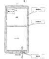
図2に、本発明の実施の一形態に係る端末装置1の内部構造の概略を示す。端末装置1は、防水対応端末であり、端末装置1の筐体の外周部を防水テープ、ゴムまたは接着剤等で封止することで、防水性能(気密性)を持たせている。
図2に、本発明の実施の一形態に係る端末装置1の内部構造の概略を示す。端末装置1は、防水対応端末であり、端末装置1の筐体の外周部を防水テープ、ゴムまたは接着剤等で封止することで、防水性能(気密性)を持たせている。
しかしながら、筐体を完全に密封してしまうと筐体の内外の気圧値に差が出てしまうため、後述する通気膜を備えることで筐体の内部の気圧値を外部と等しくしている。通気膜は、水分を通さず空気のみを通過させる膜である。通気膜により、防水性を維持しつつ、筐体の内外の気圧値を等しく保つことができる。
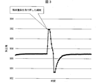
筐体に急激な物理的圧力がかかると、筐体の内部の空気は通気膜を通り外部に移動する。しかしながら、通気膜は完全な開放穴に比べ通気性に一定の条件(単位時間当たりの通気量が決まっている)があるため、圧力がかかった瞬間、筐体の内部の圧力は一時的に上昇し、その後、通気膜を通り空気が外に出ることで外圧と等しくなる(図3参照)。
〔端末装置の構成〕
図1は、端末装置1の構成を示すブロック図である。上述したように、端末装置1は、気圧値を測定する機能を有する端末装置である。同図に示すように端末装置1は、制御部10、気圧センサ20、近接センサ40、加速度センサ41、タイマ50、記憶部60および表示部70を備えている。
図1は、端末装置1の構成を示すブロック図である。上述したように、端末装置1は、気圧値を測定する機能を有する端末装置である。同図に示すように端末装置1は、制御部10、気圧センサ20、近接センサ40、加速度センサ41、タイマ50、記憶部60および表示部70を備えている。
制御部10は、端末装置1の各部を統括的に制御する。図1に示すように、制御部10は、センサ制御部11、接触状態検知部(接触検知部)12、記録制御部13、表示制御部14、信頼度設定部15、および情報処理部16を備えている。
センサ制御部11は、気圧センサ20を用いて気圧値を測定する。また、センサ制御部11は、気圧センサ20およびフィルタ30の動作を制御する。また、センサ制御部11は、フィルタ30および測定値取得部111を備えており、気圧センサ20の検知信号に基づいて生成される気圧値に係る情報を取得する。また、センサ制御部11は、端末装置1と物体との接触が検知された場合に、情報処理部16への気圧値の出力形態を変更する。
例えば、センサ制御部11は、端末装置1と物体との接触が検知されたか否かに応じて、フィルタ30の係数を変更する。具体的には、フィルタ30の係数をハードモードまたはノーマルモードに切り替える。
フィルタ30は、測定される気圧値の変化を滑らかなものとする(緩和する)機能を有しており、例えば、LPF(ローパスフィルタ)などで構成される。フィルタ30をハードモードまたはノーマルモードに切り替えるとは、例えば、フィルタ30をオン状態またはオフ状態にする、もしくはフィルタ30の係数を急峻なものまたは緩やかなものに切り替えることである。
端末装置1と物体との接触が検知された場合、センサ制御部11は、フィルタ30をオン状態にする。一方、端末装置1と物体との接触が検知されなかった場合、センサ制御部11は、フィルタ30をオフ状態にする。
気圧センサ20は、気圧値を測定する。また、気圧センサ20による測定値取得時のノイズ(過度な応答値)を低減するためにフィルタ30を通すことで、測定される気圧値の細かな変動が減少し、比較的安定した気圧値を取得することが可能になる。
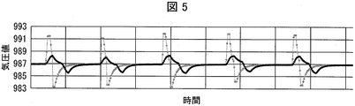
図5に示すように、フィルタ30(本実施形態ではLPFであるものとする)を通して測定される気圧の測定値は、フィルタ30をかけないときの気圧の測定値(細い実線のグラフ参照)に対して、比較的緩やかな変化(太い実線のグラフ参照)になる。図5に示すグラフは、擬似的に端末装置1の筐体に圧力を加えた際(5回)の気圧値を測定した結果を示す。フィルタ30を通して測定される気圧の測定値は、フィルタ30をかけないときの気圧の測定値に見られる急峻な変化がなくなり、滑らかな変化となる。但し、変化のタイミングに対して遅れての応答になる。
本実施形態では、「物理的な圧力により急峻な変化が想定される場合=接触検知状態」の場合に、フィルタ30をオン状態とすることで、急峻な変化を低減しつつ、応答の遅れも最低限に留めることが可能である。
また、センサ制御部11は、端末装置1と物体との接触が検知された場合に、上記検知後に測定された上記気圧値を上記検知前に測定された上記気圧値に差し替えて出力しても良い。これにより、端末装置1と物体との接触の影響を受けた不正確な気圧値を、端末装置1と物体との接触の影響を受けていない状態で測定された気圧値に差し替えることが可能になる。
また、センサ制御部11は、端末装置1と物体との接触が検知された場合に、測定された上記気圧値を、上記検知前より低く設定された信頼度と共に出力しても良い。これにより、端末装置1と物体との接触が検知された場合に、気圧値がその信頼度とともに出力される。このため、気圧値に対して、信頼度に応じた情報処理を行うことができる。
接触状態検知部12は、端末装置1と物体との接触を検知する。より具体的には、接触状態検知部12は、端末装置1と物体との接触が検知されたか否かを判定する。なお、接触状態検知部12は、本実施形態では、近接センサ40を用いて端末装置1に物体が接触しているか否かを判定する構成を採用しているが、このような構成に限定されない。例えば、静電センサやタッチパネル等を用い、端末装置1に物体が接触していることを検知する構成としても良い。また、歪センサや圧力センサなどを用いて、端末装置1に力が加わっていることを検知しても同様の効果が得られる。
また、接触を検知している状態とは、端末装置1の筐体が何らかの力を加えられる可能性を持っている状態であると仮定できる。逆に言えば、如何なる物体も接触状態にない状態で、端末装置1に外部から物理的な圧力を加えることは容易ではない。近接センサ40の配置位置としては、端末装置1の筐体の少なくとも一面(例えば、表示面)に、少なくとも一つの近接センサ40を備えるように構成する。近接センサ40を配置する面は、筐体が押されることで影響を受けやすい面(もしくはその対面)であることが望ましい。
記録制御部13は、センサ制御部11が取得する気圧値を記憶部60に記録する制御を行う。また、記録制御部13は、測定した気圧値を測定した時刻に関連付けて記憶部60に記憶させる。
表示制御部14は、表示部70による表示を制御する。信頼度設定部15は、端末装置1と物体との接触が検知された場合に、測定した気圧値の信頼度が低いと設定し、端末装置1と物体との接触が検知されなかった場合に、測定した気圧値の信頼度が高いと設定する。
情報処理部16は、センサ制御部11から出力される気圧値を用いて情報処理を行い、該情報処理の結果を表示制御部14に出力する。例えば、情報処理部16は、センサ制御部11から出力される気圧値を用いて端末装置1が存在している場所の高度を算出する。
近接センサ40および加速度センサ41は、物体の接触を検知するためのセンサである。タイマ50は、気圧値を測定した時刻等を計測する。記憶部60は、測定した気圧値を測定した時刻等に関連付けて記憶する。表示部70は、例えば液晶パネルが使用される。但し、表示部70に使用される表示パネルは、液晶パネルに限定されるものではなく、有機EL(エレクトロルミネッセンス)パネル、無機ELパネル、プラズマパネル等であってもよい。
(端末装置1の作用効果)
端末装置1によれば、接触状態検知部12は、端末装置1と物体との接触を検知する。一般に、端末装置1と物体が接触状態にある場合、端末装置1には外部から圧力が加わる可能性のある状態にある。このため、端末装置1と物体との接触を検知することにより、端末装置1に圧力がかかっていると推定することができる。また、端末装置1によれば、センサ制御部11は、端末装置1と物体との接触が検知された場合に、情報処理部16への気圧値の出力形態を変更する。これにより、端末装置1と物体とが接触して圧力がかかっている場合に、測定される気圧値の出力形態を圧力がかかっている状態に合わせた態様にすることが可能になる。以上により、端末装置1によれば、物体が接触して圧力がかかっている場合に、測定された気圧値を、圧力がかかっている状態で測定された気圧値として適正に情報処理することができる。
端末装置1によれば、接触状態検知部12は、端末装置1と物体との接触を検知する。一般に、端末装置1と物体が接触状態にある場合、端末装置1には外部から圧力が加わる可能性のある状態にある。このため、端末装置1と物体との接触を検知することにより、端末装置1に圧力がかかっていると推定することができる。また、端末装置1によれば、センサ制御部11は、端末装置1と物体との接触が検知された場合に、情報処理部16への気圧値の出力形態を変更する。これにより、端末装置1と物体とが接触して圧力がかかっている場合に、測定される気圧値の出力形態を圧力がかかっている状態に合わせた態様にすることが可能になる。以上により、端末装置1によれば、物体が接触して圧力がかかっている場合に、測定された気圧値を、圧力がかかっている状態で測定された気圧値として適正に情報処理することができる。
〔端末装置の動作の例(その1)〕
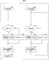
次に、図4に示すフローチャートに基づき、端末装置1の動作の一例について説明する。図4の(a)は、単発で気圧値を測定する場合の動作の流れを示すフローチャートである。また、図4の(b)は、連続で気圧値を測定する場合(バックグラウンドで継続的に気圧値を測定する場合)の動作の流れを示すフローチャートである。
次に、図4に示すフローチャートに基づき、端末装置1の動作の一例について説明する。図4の(a)は、単発で気圧値を測定する場合の動作の流れを示すフローチャートである。また、図4の(b)は、連続で気圧値を測定する場合(バックグラウンドで継続的に気圧値を測定する場合)の動作の流れを示すフローチャートである。
図4の(a)に示すようにステップS(以下、「ステップ」は省略する)101では、気圧の測定を開始して、S102に進む。S102では、接触状態検知部12が、近接センサ40による検知結果に基づき、端末装置1と物体との接触が検知されたか否かを判定する。その結果、端末装置1と物体との接触が検知された場合には、S103に進む。一方、端末装置1と物体との接触が検知されなかった場合は、S104に進む。
S103では、センサ制御部11がフィルタ30の係数をハードモードに切り替えてS105に進む。S104では、センサ制御部11がフィルタ30の係数をノーマルモードに切り替えてS105に進む。
S105では、センサ制御部11が、近接センサ40およびフィルタ30を介して気圧値を測定し、測定値取得部111が、検知した気圧の測定値(気圧値)を取得して、記憶部60に記録し、S106に進み、気圧測定を完了する。
次に、図4の(b)に示すようにS201では、気圧の測定を開始して、S202に進む。S202では、接触状態検知部12が、近接センサ40による検知結果に基づき、端末装置1と物体との接触が検知されたか否かを判定する。その結果、端末装置1と物体との接触が検知された場合には、S203に進む。一方、端末装置1と物体との接触が検知されなかった場合は、S204に進む。
S203では、センサ制御部11がフィルタ30の係数をハードモードに切り替えてS205に進む。S204では、センサ制御部11がフィルタ30の係数をノーマルモードに切り替えてS205に進む。
S205では、センサ制御部11が、近接センサ40およびフィルタ30を介して気圧値を測定し、測定値取得部111が、検知した気圧の測定値(気圧値)を取得して、記憶部60に記録し、S202に戻る。
〔端末装置の動作の例(その2)〕
次に、図6に示すフローチャートに基づき、端末装置1の動作の別の例について説明する。図6の(a)は、単発で気圧値を測定する場合の動作の流れを示すフローチャートである。また、図6の(b)は、連続で気圧値を測定する場合(バックグラウンドで継続的に気圧値を測定する場合)の動作の流れを示すフローチャートである。
次に、図6に示すフローチャートに基づき、端末装置1の動作の別の例について説明する。図6の(a)は、単発で気圧値を測定する場合の動作の流れを示すフローチャートである。また、図6の(b)は、連続で気圧値を測定する場合(バックグラウンドで継続的に気圧値を測定する場合)の動作の流れを示すフローチャートである。
図6の(a)に示すようにS301では、気圧の測定を開始して、S302に進む。S302では、接触状態検知部12が、近接センサ40による検知結果に基づき、端末装置1と物体との接触が検知されたか否かを判定する。その結果、端末装置1と物体との接触が検知された場合には、S303に進む。一方、端末装置1と物体との接触が検知されなかった場合は、S304に進む。
S303では、センサ制御部11は、情報処理部16に対して前回(検知前)に記録した気圧値を測定値として出力し、S305に進む。一方、S304では、センサ制御部11は、情報処理部16に対して現在(検知後)測定した気圧値を測定値として出力し、S305に進む。S305では、記録制御部13が、出力した気圧値を同時に記憶部60の記憶領域に保存させ、S306に進み、気圧測定を完了する。
次に、図6の(b)に示すようにS401では、気圧の測定を開始して、S402に進む。S402では、接触状態検知部12が、近接センサ40による検知結果に基づき、端末装置1と物体との接触が検知されたか否かを判定する。その結果、端末装置1と物体との接触が検知された場合には、S403に進む。一方、端末装置1と物体との接触が検知されなかった場合は、S404に進む。
S403では、センサ制御部11は、情報処理部16に対して、前回(検知前)に記録した気圧値を測定値として出力し、S405に進む。一方、S404では、センサ制御部11は、情報処理部16に対して、現在(検知後)測定した気圧値を測定値として出力し、S405に進む。
S405では、記録制御部13が、出力した気圧値を同時に記憶部60の記憶領域に保存させ、S402に戻る。
〔端末装置の動作の例(その3)〕
次に、図7に示すフローチャートに基づき、端末装置1の動作のさらに別の例について説明する。図7の(a)は、単発で気圧値を測定する場合の動作の流れを示すフローチャートである。また、図7の(b)は、連続で気圧値を測定する場合(バックグラウンドで継続的に気圧値を測定する場合)の動作の流れを示すフローチャートである。
次に、図7に示すフローチャートに基づき、端末装置1の動作のさらに別の例について説明する。図7の(a)は、単発で気圧値を測定する場合の動作の流れを示すフローチャートである。また、図7の(b)は、連続で気圧値を測定する場合(バックグラウンドで継続的に気圧値を測定する場合)の動作の流れを示すフローチャートである。
図7の(a)に示すようにS501では、気圧の測定を開始して、S502に進む。S502では、センサ制御部11が気圧センサ20を介して気圧値を測定し、測定値取得部111が、気圧の測定値(気圧値)を取得してS503に進む。
S503では、接触状態検知部12が、近接センサ40による検知結果に基づき、端末装置1と物体との接触が検知されたか否かを判定する。その結果、端末装置1と物体との接触が検知された場合には、S504に進む。一方、端末装置1と物体との接触が検知されなかった場合は、S505に進む。
S504では、信頼度設定部15が、気圧値に信頼度情報を「低」として設定し、S506に進む。一方、S505では、信頼度設定部15が、気圧値に信頼度情報を「高」として設定し、S506に進む。
S506では、センサ制御部11が、情報処理部16に対して、気圧値をその信頼度を示す情報と共に出力し、S507に進み気圧測定を完了する。
次に、図7の(b)に示すようにS601では、気圧の測定を開始して、S602に進む。S602では、センサ制御部11が気圧センサ20を介して気圧値を測定し、測定値取得部111が、気圧の測定値(気圧値)を取得してS603に進む。
S603では、接触状態検知部12が、近接センサ40による検知結果に基づき、端末装置1と物体との接触が検知されたか否かを判定する。その結果、端末装置1と物体との接触が検知された場合には、S604に進む。一方、端末装置1と物体との接触が検知されなかった場合は、S605に進む。
S604では、信頼度設定部15が、気圧値に信頼度情報を「低」として設定し、S606に進む。一方、S605では、信頼度設定部15が、気圧値に信頼度情報を「高」として設定し、S606に進む。
S606では、センサ制御部11が、情報処理部16に対して気圧値をその信頼度を示す情報と共に出力し、S602に戻る。
〔端末装置の動作の例(その4)〕
次に、図8に示すフローチャートに基づき、端末装置1の動作のさらに別の例について説明する。図8の(a)は、単発で気圧値を測定する場合の動作の流れを示すフローチャートである。また、図8の(b)は、連続で気圧値を測定する場合(バックグラウンドで継続的に気圧値を測定する場合)の動作の流れを示すフローチャートである。
次に、図8に示すフローチャートに基づき、端末装置1の動作のさらに別の例について説明する。図8の(a)は、単発で気圧値を測定する場合の動作の流れを示すフローチャートである。また、図8の(b)は、連続で気圧値を測定する場合(バックグラウンドで継続的に気圧値を測定する場合)の動作の流れを示すフローチャートである。
図8の(a)に示すようにS701では、気圧の測定を開始して、S702に進む。S702では、接触状態検知部12が、近接センサ40による検知結果に基づき、端末装置1と物体との接触が検知されたか否かを判定する。その結果、端末装置1と物体との接触が検知された場合には、S703に進む。一方、端末装置1と物体との接触が検知されなかった場合は、S705に進む。
S703では、接触状態検知部12が、加速度センサ41により加速度が検知されたか否かを判定する。その結果、加速度が検知された場合は、S704に進む。一方、加速度が検知されなかった場合は、S705に進む。
S704では、センサ制御部11がフィルタ30の係数をハードモードに切り替えてS706に進む。S705では、センサ制御部11がフィルタ30の係数をノーマルモードに切り替えてS706に進む。
S706では、センサ制御部11が、近接センサ40およびフィルタ30を介して気圧値を測定し、測定値取得部111が、検知した気圧の測定値(気圧値)を取得して、S707に進み、気圧測定を完了する。
次に、図8の(b)に示すようにS801では、気圧の測定を開始して、S802に進む。S802では、接触状態検知部12が、近接センサ40による検知結果に基づき、端末装置1と物体との接触が検知されたか否かを判定する。その結果、端末装置1と物体との接触が検知された場合には、S803に進む。一方、端末装置1と物体との接触が検知されなかった場合は、S805に進む。
S803では、接触状態検知部12が、加速度センサ41により加速度が検知されたか否かを判定する。その結果、加速度が検知された場合は、S804に進む。一方、加速度が検知されなかった場合は、S805に進む。
S804では、センサ制御部11がフィルタ30の係数をハードモードに切り替えてS806に進む。S805では、センサ制御部11がフィルタ30の係数をノーマルモードに切り替えてS806に進む。
S806では、センサ制御部11が、近接センサ40およびフィルタ30を介して気圧値を測定し、測定値取得部111が、検知した気圧の測定値(気圧値)を取得して、S802に戻る。
〔端末装置の動作の例(その5)〕
次に、図9に示すフローチャートに基づき、端末装置1の動作のさらに別の例について説明する。図9の(a)は、単発で気圧値を測定する場合の動作の流れを示すフローチャートである。また、図9の(b)は、連続で気圧値を測定する場合(バックグラウンドで継続的に気圧値を測定する場合)の動作の流れを示すフローチャートである。
次に、図9に示すフローチャートに基づき、端末装置1の動作のさらに別の例について説明する。図9の(a)は、単発で気圧値を測定する場合の動作の流れを示すフローチャートである。また、図9の(b)は、連続で気圧値を測定する場合(バックグラウンドで継続的に気圧値を測定する場合)の動作の流れを示すフローチャートである。
図9の(a)に示すフローチャートは、図8の(a)に示すフローチャートのS704、S705およびS706のそれぞれをS714、S715およびS716で置き換えたものとなっており、その他の各ステップの流れは、図8の(a)に示すフローチャートと概ね同様である。
S714では、センサ制御部11は、情報処理部16に対して、前回(検知前)に記録した気圧値を測定値として出力し、S716に進む。一方、S715では、センサ制御部11は、情報処理部16に対して、現在(検知後)測定した気圧値を測定値として出力し、S716に進む。S716では、記録制御部13が、出力した気圧値を同時に記憶部60の記憶領域に保存させ、S707に進み、気圧測定を完了する。
次に、図9の(b)に示すフローチャートは、図8の(b)に示すフローチャートのS804、S805およびS806のそれぞれをS814、S815およびS816で置き換えたものとなっており、その他の各ステップの流れは、図8の(b)に示すフローチャートと概ね同様である。
S814では、センサ制御部11は、情報処理部16に対して、前回(検知前)に記録した気圧値を測定値として出力し、S816に進む。一方、S815では、センサ制御部11は、情報処理部16に対して、現在(検知後)測定した気圧値を測定値とし出力し、S816に進む。S816では、記録制御部13が、出力した気圧値を同時に記憶部60の記憶領域に保存させ、S802に戻る。
〔端末装置の動作の例(その6)〕
次に、図10に示すフローチャートに基づき、端末装置1の動作のさらに別の例について説明する。図10の(a)は、単発で気圧値を測定する場合の動作の流れを示すフローチャートである。また、図10の(b)は、連続で気圧値を測定する場合(バックグラウンドで継続的に気圧値を測定する場合)の動作の流れを示すフローチャートである。
次に、図10に示すフローチャートに基づき、端末装置1の動作のさらに別の例について説明する。図10の(a)は、単発で気圧値を測定する場合の動作の流れを示すフローチャートである。また、図10の(b)は、連続で気圧値を測定する場合(バックグラウンドで継続的に気圧値を測定する場合)の動作の流れを示すフローチャートである。
図10の(a)に示すフローチャートは、図8の(a)に示すフローチャートのS704、S705およびS706のそれぞれをS724、S725およびS726で置き換えたものとなっており、その他の各ステップの流れは、図8の(a)に示すフローチャートと概ね同様である。
S724では、信頼度設定部15が、気圧値に信頼度情報を「低」として設定し、S726に進む。一方、S725では、信頼度設定部15が、気圧値に信頼度情報を「高」として設定し、S726に進む。
S726では、センサ制御部11が、情報処理部16に対して気圧値をその信頼度を示す情報と共に出力し、S707に進み気圧測定を完了する。
次に、図10の(b)に示すフローチャートは、図8の(b)に示すフローチャートのS804、S805およびS806のそれぞれをS824、S825およびS826で置き換えたものとなっており、その他の各ステップの流れは、図8の(b)に示すフローチャートと概ね同様である。
S824では、信頼度設定部15が、気圧値に信頼度情報を「低」として設定し、S826に進む。一方、S825では、信頼度設定部15が、気圧値に信頼度情報を「高」として設定し、S826に進む。
S826では、センサ制御部11が、情報処理部16に対して、気圧値をその信頼度を示す情報と共に出力し、S802に戻る。
〔ソフトウェアによる実現例〕
端末装置1の制御部10における制御ブロック(特に、センサ制御部11、信頼度設定部15および情報処理部16)は、集積回路(ICチップ)等に形成された論理回路(ハードウェア)によって実現してもよいし、CPU(Central Processing Unit)を用いてソフトウェアによって実現してもよい。
端末装置1の制御部10における制御ブロック(特に、センサ制御部11、信頼度設定部15および情報処理部16)は、集積回路(ICチップ)等に形成された論理回路(ハードウェア)によって実現してもよいし、CPU(Central Processing Unit)を用いてソフトウェアによって実現してもよい。
後者の場合、端末装置1の制御部10は、各機能を実現するソフトウェアであるプログラムの命令を実行するCPU、上記プログラムおよび各種データがコンピュータ(またはCPU)で読み取り可能に記録されたROM(Read Only Memory)または記憶装置(これらを「記録媒体」と称する)、上記プログラムを展開するRAM(Random Access Memory)などを備えている。そして、コンピュータ(またはCPU)が上記プログラムを上記記録媒体から読み取って実行することにより、本発明の目的が達成される。上記記録媒体としては、「一時的でない有形の媒体」、例えば、テープ、ディスク、カード、半導体メモリ、プログラマブルな論理回路などを用いることができる。また、上記プログラムは、該プログラムを伝送可能な任意の伝送媒体(通信ネットワークや放送波等)を介して上記コンピュータに供給されてもよい。なお、本発明の一態様は、上記プログラムが電子的な伝送によって具現化された、搬送波に埋め込まれたデータ信号の形態でも実現され得る。
〔まとめ〕
本発明の態様1に係る端末装置(1)は、気圧値を測定する機能を有する端末装置であって、上記端末装置と物体との接触を検知する接触検知部(接触状態検知部12)と、気圧センサ(20)を用いて気圧値を測定するセンサ制御部(11)と、測定された上記気圧値を用いて情報処理を行い、該情報処理の結果を出力する情報処理部(16)と、を備え、上記センサ制御部は、上記端末装置と物体との接触が検知された場合に、上記情報処理部への上記気圧値の出力形態を変更し、上記情報処理部は、上記端末装置と物体との接触が検知された場合に、上記出力形態が変更された上記気圧値を用いて情報処理を行う構成である。
本発明の態様1に係る端末装置(1)は、気圧値を測定する機能を有する端末装置であって、上記端末装置と物体との接触を検知する接触検知部(接触状態検知部12)と、気圧センサ(20)を用いて気圧値を測定するセンサ制御部(11)と、測定された上記気圧値を用いて情報処理を行い、該情報処理の結果を出力する情報処理部(16)と、を備え、上記センサ制御部は、上記端末装置と物体との接触が検知された場合に、上記情報処理部への上記気圧値の出力形態を変更し、上記情報処理部は、上記端末装置と物体との接触が検知された場合に、上記出力形態が変更された上記気圧値を用いて情報処理を行う構成である。
上記構成によれば、接触検知部は、端末装置と物体との接触を検知する。一般に、物体が端末装置と接触状態にある場合、端末装置には外部から圧力が加わる可能性のある状態にある。このため、端末装置と物体との接触を検知することにより、端末装置に圧力がかかっていると推定することができる。また、上記構成によれば、センサ制御部は、端末装置と物体との接触が検知された場合に、情報処理部への気圧値の出力形態を変更する。これにより、端末装置と物体とが接触して圧力がかかっている場合に、測定される気圧値の出力形態を圧力がかかっている状態に合わせた態様にすることが可能になる。以上により、上記構成によれば、物体が接触して圧力がかかっている場合に、測定された気圧値を、圧力がかかっている状態で測定された気圧値として適正に情報処理することができる。
本発明の態様2に係る端末装置は、上記態様1において、上記センサ制御部は、上記端末装置と物体との接触が検知された場合に、測定された上記気圧値の変化を滑らかなものとするためにフィルタをオン状態にしても良い。上記構成によれば、測定される気圧値の急峻な変化を低減しつつ応答の遅れを最低限に留めることができる。
また、本発明の態様3に係る端末装置は、上記態様1において、上記センサ制御部は、上記端末装置と物体との接触が検知された場合に、上記検知後に測定された上記気圧値を上記検知前に測定された上記気圧値に差し替えて出力しても良い。上記構成によれば、上記端末装置と物体との接触が検知された場合に、検知後に測定された気圧値を検知前に測定された気圧値に差し替えて出力する。これにより、端末装置と物体との接触の影響を受けた不正確な気圧値を、端末装置と物体との接触の影響を受けていない状態で測定された気圧値に差し替えることが可能になる。
また、本発明の態様4に係る端末装置は、上記態様1において、上記センサ制御部は、上記端末装置と物体との接触が検知された場合に、測定された上記気圧値を、上記検知前より低く設定された信頼度と共に出力しても良い。上記構成によれば、端末装置と物体との接触が検知された場合に、気圧値がその信頼度とともに出力される。このため、気圧値に対して、信頼度に応じた情報処理を行うことができる。
また、本発明の態様5に係る端末装置の制御方法は、気圧値を測定する機能を有する端末装置の制御方法であって、上記端末装置と物体との接触を検知する接触検知ステップと、気圧センサを用いて気圧値を測定する気圧測定ステップと、測定された上記気圧値を用いて情報処理を行い、該情報処理の結果を出力する情報処理ステップと、を含み、上記端末装置と物体との接触を検知した場合に、上記気圧測定ステップで測定された上記気圧値の出力形態を変更し、上記情報処理ステップで上記出力形態が変更された上記気圧値を用いて情報処理を行う方法である。上記方法によれば、上記態様1に係る発明と同様の効果が得られる。
本発明の各態様に係る端末装置は、コンピュータによって実現してもよく、この場合には、コンピュータを上記端末装置が備える各部(ソフトウェア要素)として動作させることにより上記端末装置をコンピュータにて実現させる端末装置の制御プログラム、およびそれを記録したコンピュータ読み取り可能な記録媒体も、本発明の範疇に入る。
〔付記事項〕
本発明は上述した各実施形態に限定されるものではなく、請求項に示した範囲で種々の変更が可能であり、異なる実施形態にそれぞれ開示された技術的手段を適宜組み合わせて得られる実施形態についても本発明の技術的範囲に含まれる。さらに、各実施形態にそれぞれ開示された技術的手段を組み合わせることにより、新しい技術的特徴を形成することができる。
本発明は上述した各実施形態に限定されるものではなく、請求項に示した範囲で種々の変更が可能であり、異なる実施形態にそれぞれ開示された技術的手段を適宜組み合わせて得られる実施形態についても本発明の技術的範囲に含まれる。さらに、各実施形態にそれぞれ開示された技術的手段を組み合わせることにより、新しい技術的特徴を形成することができる。
1 端末装置
10 制御部
11 センサ制御部
12 接触状態検知部(接触検知部)
13 記録制御部
14 表示制御部
15 信頼度設定部
16 情報処理部
20 気圧センサ
30 フィルタ
40 近接センサ
41 加速度センサ
50 タイマ
60 記憶部
70 表示部
111 測定値取得部
10 制御部
11 センサ制御部
12 接触状態検知部(接触検知部)
13 記録制御部
14 表示制御部
15 信頼度設定部
16 情報処理部
20 気圧センサ
30 フィルタ
40 近接センサ
41 加速度センサ
50 タイマ
60 記憶部
70 表示部
111 測定値取得部
Claims (6)
- 気圧値を測定する機能を有する端末装置であって、
上記端末装置と物体との接触を検知する接触検知部と、
気圧センサを用いて気圧値を測定するセンサ制御部と、
測定された上記気圧値を用いて情報処理を行い、該情報処理の結果を出力する情報処理部と、を備え、
上記センサ制御部は、上記端末装置と物体との接触が検知された場合に、上記情報処理部への上記気圧値の出力形態を変更し、
上記情報処理部は、上記端末装置と物体との接触が検知された場合に、上記出力形態が変更された上記気圧値を用いて情報処理を行うことを特徴とする端末装置。 - 上記センサ制御部は、
上記端末装置と物体との接触が検知された場合に、測定された上記気圧値の変化を滑らかなものとするためにフィルタをオン状態にすることを特徴とする請求項1に記載の端末装置。 - 上記センサ制御部は、
上記端末装置と物体との接触が検知された場合に、上記検知後に測定された上記気圧値を上記検知前に測定された上記気圧値に差し替えて出力することを特徴とする請求項1に記載の端末装置。 - 上記センサ制御部は、
上記端末装置と物体との接触が検知された場合に、測定された上記気圧値を、上記検知前より低く設定された信頼度と共に出力することを特徴とする請求項1に記載の端末装置。 - 気圧値を測定する機能を有する端末装置の制御方法であって、
上記端末装置と物体との接触を検知する接触検知ステップと、
気圧センサを用いて気圧値を測定する気圧測定ステップと、
測定された上記気圧値を用いて情報処理を行い、該情報処理の結果を出力する情報処理ステップと、を含み、
上記端末装置と物体との接触を検知した場合に、上記気圧測定ステップで測定された上記気圧値の出力形態を変更し、上記情報処理ステップで上記出力形態が変更された上記気圧値を用いて情報処理を行うことを特徴とする端末装置の制御方法。 - 請求項1に記載の端末装置としてコンピュータを機能させるための制御プログラムであって、上記センサ制御部および上記情報処理部としてコンピュータを機能させるための制御プログラム。
Priority Applications (1)
| Application Number | Priority Date | Filing Date | Title |
|---|---|---|---|
| JP2019525124A JPWO2018235385A1 (ja) | 2017-06-19 | 2018-04-05 | 端末装置およびその制御方法、ならびに制御プログラム |
Applications Claiming Priority (2)
| Application Number | Priority Date | Filing Date | Title |
|---|---|---|---|
| JP2017-119479 | 2017-06-19 | ||
| JP2017119479 | 2017-06-19 |
Publications (1)
| Publication Number | Publication Date |
|---|---|
| WO2018235385A1 true WO2018235385A1 (ja) | 2018-12-27 |
Family
ID=64737016
Family Applications (1)
| Application Number | Title | Priority Date | Filing Date |
|---|---|---|---|
| PCT/JP2018/014535 Ceased WO2018235385A1 (ja) | 2017-06-19 | 2018-04-05 | 端末装置およびその制御方法、ならびに制御プログラム |
Country Status (2)
| Country | Link |
|---|---|
| JP (1) | JPWO2018235385A1 (ja) |
| WO (1) | WO2018235385A1 (ja) |
Citations (3)
| Publication number | Priority date | Publication date | Assignee | Title |
|---|---|---|---|---|
| JP2012208010A (ja) * | 2011-03-30 | 2012-10-25 | Yokosuka Telecom Research Park:Kk | 測位装置、測位システム、測位方法、プログラム |
| JP2015021771A (ja) * | 2013-07-17 | 2015-02-02 | 株式会社デンソー | 圧力センサ |
| JP2015122649A (ja) * | 2013-12-24 | 2015-07-02 | 京セラ株式会社 | 携帯電子機器、制御方法、及び制御プログラム |
-
2018
- 2018-04-05 WO PCT/JP2018/014535 patent/WO2018235385A1/ja not_active Ceased
- 2018-04-05 JP JP2019525124A patent/JPWO2018235385A1/ja active Pending
Patent Citations (3)
| Publication number | Priority date | Publication date | Assignee | Title |
|---|---|---|---|---|
| JP2012208010A (ja) * | 2011-03-30 | 2012-10-25 | Yokosuka Telecom Research Park:Kk | 測位装置、測位システム、測位方法、プログラム |
| JP2015021771A (ja) * | 2013-07-17 | 2015-02-02 | 株式会社デンソー | 圧力センサ |
| JP2015122649A (ja) * | 2013-12-24 | 2015-07-02 | 京セラ株式会社 | 携帯電子機器、制御方法、及び制御プログラム |
Also Published As
| Publication number | Publication date |
|---|---|
| JPWO2018235385A1 (ja) | 2020-04-02 |
Similar Documents
| Publication | Publication Date | Title |
|---|---|---|
| US10148857B2 (en) | Electronic device and method for sensing touch force | |
| US8456430B2 (en) | Tactile user interface for an electronic device | |
| US9367100B2 (en) | Electronic devices with submersion detection circuitry | |
| EP2821897B1 (en) | Finger detection on touch screens for mobile devices | |
| CN104620189B (zh) | 具有微机电系统运动传感器的移动设备硬件姿态检测实现 | |
| US10222890B2 (en) | Pressure sensing panel and method for fabricating the same, display device and force touch method | |
| WO2015015047A1 (en) | Distance estimation | |
| WO2018000874A1 (zh) | 一种触摸压力检测装置、显示屏及触控电子设备 | |
| CN107357411B (zh) | 电子装置 | |
| SG169951A1 (en) | Cellular phone having navigation device, correcting value initializing method, and navigation function | |
| CN106225806B (zh) | 校准磁传感器的方法、装置及移动终端 | |
| US7921572B2 (en) | Accuracy indications for an electronic compass in a portable device | |
| CN107782280A (zh) | 一种检测方法和移动终端 | |
| US20170220144A1 (en) | Force sensitive touch panel devices | |
| US20130201102A1 (en) | Mobile communication device with three-dimensional sensing and a method therefore | |
| CN112424741B (zh) | 用于显示关于触控笔的信息的电子设备及其方法 | |
| JP2015087201A (ja) | 電子機器 | |
| US8543852B2 (en) | Method and system for determining an idle state | |
| US10656737B2 (en) | Electronic device, control device, storage medium, and control method for calibration after impact detection | |
| WO2018235385A1 (ja) | 端末装置およびその制御方法、ならびに制御プログラム | |
| WO2015007001A1 (zh) | 空间鼠标的数据处理方法以及鼠标指针的控制方法 | |
| CN106525067B (zh) | 一种计步器的控制方法、装置及移动终端 | |
| CN106293006B (zh) | 运行磁传感器校准算法库的方法、装置及移动终端 | |
| WO2017056891A1 (ja) | 情報処理装置、電子機器、情報処理装置の制御方法、および制御プログラム | |
| JP6351946B2 (ja) | 携帯端末、および制御方法 |
Legal Events
| Date | Code | Title | Description |
|---|---|---|---|
| 121 | Ep: the epo has been informed by wipo that ep was designated in this application |
Ref document number: 18819577 Country of ref document: EP Kind code of ref document: A1 |
|
| ENP | Entry into the national phase |
Ref document number: 2019525124 Country of ref document: JP Kind code of ref document: A |
|
| NENP | Non-entry into the national phase |
Ref country code: DE |
|
| 122 | Ep: pct application non-entry in european phase |
Ref document number: 18819577 Country of ref document: EP Kind code of ref document: A1 |