WO2018235175A1 - Chair - Google Patents
Chair Download PDFInfo
- Publication number
- WO2018235175A1 WO2018235175A1 PCT/JP2017/022760 JP2017022760W WO2018235175A1 WO 2018235175 A1 WO2018235175 A1 WO 2018235175A1 JP 2017022760 W JP2017022760 W JP 2017022760W WO 2018235175 A1 WO2018235175 A1 WO 2018235175A1
- Authority
- WO
- WIPO (PCT)
- Prior art keywords
- guide
- seat
- tilt
- base portion
- guide portion
- Prior art date
Links
Images


Classifications
-
- A—HUMAN NECESSITIES
- A47—FURNITURE; DOMESTIC ARTICLES OR APPLIANCES; COFFEE MILLS; SPICE MILLS; SUCTION CLEANERS IN GENERAL
- A47C—CHAIRS; SOFAS; BEDS
- A47C3/00—Chairs characterised by structural features; Chairs or stools with rotatable or vertically-adjustable seats
- A47C3/02—Rocking chairs
- A47C3/025—Rocking chairs with seat, or seat and back-rest unit elastically or pivotally mounted in a rigid base frame
- A47C3/026—Rocking chairs with seat, or seat and back-rest unit elastically or pivotally mounted in a rigid base frame with central column, e.g. rocking office chairs; Tilting chairs
-
- A—HUMAN NECESSITIES
- A47—FURNITURE; DOMESTIC ARTICLES OR APPLIANCES; COFFEE MILLS; SPICE MILLS; SUCTION CLEANERS IN GENERAL
- A47C—CHAIRS; SOFAS; BEDS
- A47C3/00—Chairs characterised by structural features; Chairs or stools with rotatable or vertically-adjustable seats
- A47C3/02—Rocking chairs
- A47C3/025—Rocking chairs with seat, or seat and back-rest unit elastically or pivotally mounted in a rigid base frame
- A47C3/0255—Rocking chairs with seat, or seat and back-rest unit elastically or pivotally mounted in a rigid base frame pivotally mounted in the base frame, e.g. swings
-
- A—HUMAN NECESSITIES
- A47—FURNITURE; DOMESTIC ARTICLES OR APPLIANCES; COFFEE MILLS; SPICE MILLS; SUCTION CLEANERS IN GENERAL
- A47C—CHAIRS; SOFAS; BEDS
- A47C3/00—Chairs characterised by structural features; Chairs or stools with rotatable or vertically-adjustable seats
- A47C3/02—Rocking chairs
- A47C3/025—Rocking chairs with seat, or seat and back-rest unit elastically or pivotally mounted in a rigid base frame
- A47C3/0257—Rocking chairs with seat, or seat and back-rest unit elastically or pivotally mounted in a rigid base frame slidingly movable in the base frame, e.g. by rollers
-
- A—HUMAN NECESSITIES
- A47—FURNITURE; DOMESTIC ARTICLES OR APPLIANCES; COFFEE MILLS; SPICE MILLS; SUCTION CLEANERS IN GENERAL
- A47C—CHAIRS; SOFAS; BEDS
- A47C3/00—Chairs characterised by structural features; Chairs or stools with rotatable or vertically-adjustable seats
- A47C3/02—Rocking chairs
- A47C3/03—Locking members
-
- A—HUMAN NECESSITIES
- A47—FURNITURE; DOMESTIC ARTICLES OR APPLIANCES; COFFEE MILLS; SPICE MILLS; SUCTION CLEANERS IN GENERAL
- A47C—CHAIRS; SOFAS; BEDS
- A47C7/00—Parts, details, or accessories of chairs or stools
- A47C7/02—Seat parts
- A47C7/024—Seat parts with double seats
-
- A—HUMAN NECESSITIES
- A47—FURNITURE; DOMESTIC ARTICLES OR APPLIANCES; COFFEE MILLS; SPICE MILLS; SUCTION CLEANERS IN GENERAL
- A47C—CHAIRS; SOFAS; BEDS
- A47C7/00—Parts, details, or accessories of chairs or stools
- A47C7/36—Support for the head or the back
- A47C7/40—Support for the head or the back for the back
- A47C7/44—Support for the head or the back for the back with elastically-mounted back-rest or backrest-seat unit in the base frame
- A47C7/448—Support for the head or the back for the back with elastically-mounted back-rest or backrest-seat unit in the base frame with resilient blocks
-
- A—HUMAN NECESSITIES
- A47—FURNITURE; DOMESTIC ARTICLES OR APPLIANCES; COFFEE MILLS; SPICE MILLS; SUCTION CLEANERS IN GENERAL
- A47C—CHAIRS; SOFAS; BEDS
- A47C7/00—Parts, details, or accessories of chairs or stools
- A47C7/002—Chair or stool bases
- A47C7/006—Chair or stool bases with castors
Definitions
- the present invention relates to a chair suitably used in an office or the like.
- Patent Documents 1 to 5 There have conventionally been chairs that change the direction and angle of the backrest in accordance with the change in posture of a seated person.
- the chair of Patent Document 1 is configured such that a pair of back plates are respectively attached to the frame via rubber parts, turn up and down, store the repulsive force while changing the direction while compressing the rubber parts to the left and right It is done.
- the chair of Patent Document 2 is configured such that the upper half of the back of a car seat rotates around a longitudinal axis while accumulating repulsive force.
- the chair of Patent Document 3 is configured integrally with a back seat, and the lower part of the seat is supported to be able to roll around a fulcrum, and when the back seat rolls, the rubber parts arranged around the lower part are compressed,
- the back seat is configured to generate a repulsive force returning to the reference position.
- the chair of Patent Document 4 is configured integrally with a back seat, and a part of the back is fixed at a fulcrum, and the back seat is elastic by its own elasticity according to the movement of a seated person around this fulcrum A configuration is disclosed that deforms so as to twist in a front view left and right.
- the chair of Patent Document 5 is configured such that the back seat is divided into a plurality of sections and the sections are easily deformed in part and partially separated, and the sections are easily twisted and the degree of deformation is high. ing.
- Patent Document 3 although the back seat performs turning motion, the back seat is largely inclined in the same direction, so the balance of the seated person is lost, and it is difficult to remake.
- the chair of Patent Document 4 rotates so that the back twists about the fulcrum, and this is accompanied by the deformation of the seat. Therefore, when considering the lower body movement and the upper body movement, the back of the seated person is not necessarily required. It is hard to say that it matches the movement of
- the present invention pays attention to these problems, and in view of the various movements of the seat occupant, when giving the seat the left and right rocking motion in a non-conventional manner, the back to the left and right movements of the seat
- An object of the present invention is to realize a chair that can perform a corresponding new operation and can return to a predetermined position when the user is away.
- the present invention takes the following means in order to achieve such an object.
- the chair according to the present invention has a back disposed at the rear of the seat and has an operating mechanism for supporting the load received from the seated person so as to be able to pivotly move in the left and right directions in a front view.
- a part of the guide part of the mechanism is separated and the back is free to move, and it is configured to automatically return the back to the neutral position along the guide when the load is removed.
- the back can be turned in the left and right direction in front view, and at least a part of the guide portion of the operation mechanism is separated when the load is applied, and the back freely moves. Easy to adjust to various movements.
- the back of the seat returns to the neutral position reliably along the guide part, the appearance of a plurality of chairs can be easily aligned at the time of leaving the seat even if the freedom of back movement is increased, and each time the chair is seated It is possible to avoid a situation where the initial state is different.
- the reaction force in which the spine returns to the neutral position becomes large according to the turning movement amount in the left and right directions.
- the back is configured to support a backrest on the back frame via the operating mechanism, the back frame is erected behind a seat, and the backrest is the back. It is desirable that the frame be pivotally mounted in a front view, substantially clockwise or counterclockwise direction through the operation mechanism.
- the back is made to support the backrest by the back frame via the operation mechanism, and the backrest is through the operation mechanism having an elastic body. It is desirable to be configured to move against the elastic reaction force in the backward direction and in the turning direction.
- the backrest is configured such that the range of turning in the left and right direction increases as the back movement with respect to the back frame is realized in order to realize the support matched to the movement of the body.
- the seat In order to realize an appropriate support state according to the seated person's posture, the seat can be pivoted in the left and right directions as viewed from the front, and the back is separated from the seat and configured to perform left-right turning operation. Is desirable.
- the operation mechanism is constituted by a base portion and a tilt portion, and the guide portion set on the base portion side and the guide portion set on the tilt portion side are in pressure contact with each other.
- the pressure contact is loosened due to the pressure received from the seat occupant, the base and the tilt relative to the reference position according to the degree of pressure reception. It is desirable to be able to change.
- the pressure contact between the two guides is performed with an elastic body, and the elastic body is compressed by pressure reception, so that the guide portion of the tilt portion and the base portion It is desirable that the guide portions be configured to be separated.
- the operation mechanism includes a base portion fixed to the backrest and having an elastic body disposed on the back side, and a guide portion disposed at a position adjacent to the base portion and recessed on the back side.
- a tilt portion having a bottom portion side open, and a convex guide portion corresponding to the guide portion on the front side with the guide portion fitted in the guide portion via the opening of the tilt portion
- the apparatus further comprises a pressing tool fixed to the base portion, and the tilt portion be fixed to a pressure receiving portion provided at an upper end portion of the back frame.
- one of the guide portions is substantially partially oval-shaped with at least one valley and the other guide portion has at least one ridge that gently fits into it It is desirable that it has a chevron shape, and that the valley line and the ridge line can be fitted.
- one of the two guide portions is a shaft-like portion bridged vertically and horizontally, and the other guide portion is vertically and horizontally axially shaped What is a V groove which guides a member to a central position is mentioned.
- the base part and the tilt part should be provided with an engagement part which regulates the relative movement of the base part and the tilt part in cooperation with the guide part. desirable.
- one of the guide parts consists of three projections
- the other guide Preferably, the portion is shaped to receive the three protrusions, and an elastic body is disposed between the one and the other guide portions.
- a new motion commensurate with the back and forth motion of the seat is provided. It is possible to provide a new chair that can be performed and returned to a predetermined position when away from the seat.
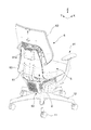
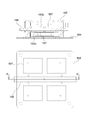
- the diagonal front perspective view of the chair which concerns on one Embodiment of this invention.
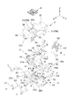
- the diagonal back perspective view which removed a part of the same chair.
- the perspective view which expands and shows a part of FIG. FIG. 5 is a perspective view of a state in which the left and right stopper mechanisms are incorporated in FIG. 4; Operation explanatory drawing of a left-right rocking part.
- FIG. 18 is a perspective view of FIG. 17 as viewed obliquely from below.
- the partially broken perspective view which shows the engagement part of the bearing and guide hole in the embodiment. The figure explaining the processing procedure of a guide hole.
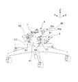
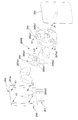
- the disassembled perspective view which shows the operation
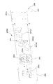
- the disassembled perspective view which shows the structure of a spine. Sectional drawing of a spine including an operating mechanism.
- the disassembled perspective view which shows the control part which controls operation
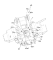
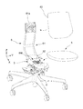
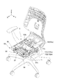
- a leg post 13 having a lifting mechanism installed therein is erected at the center of a leg blade 12 supported by a caster 11, and supported at the upper end side of the leg post 13
- the seat 5 which is a movable portion is supported via the portion 3 and the left and right swinging portion 4 which is another direction operating portion (supporting portion) operable in any of the front and rear, left and right directions.
- the front and rear rocking portion 3 is provided between the seat 5 and the support base 2 supporting the seat 5, and the left and right rocking portion 4 is provided between the front and rear rocking portion 3 and the support base 2 .
- a spine 6 is disposed.
- the support base 2 plays a role as a structure to receive the load of the seat occupant, and the bearing base portions 22 are provided on the left and right sides of the support basic body 21 having through holes 21a in the vertical direction into which the upper ends of the columns 13 are inserted.
- the pair of left and right elbow attachment portions 23 are integrally formed via the two.
- the shaft swing damper 21b is attached to the hole 21a opened in the front and rear direction surface of the support basic body 21, and the upper end portions of the left and right swing links L1 and L2 swing in the hole 22a opened in the front and rear surface of the bearing base portion 22. It is attached via the movable support shafts S1 and S2.
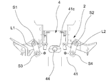
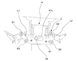
- the left and right rocking portion 4 is provided with a pair of plate-like link bases 41 which are disposed to be separated in the front and rear direction so as to perform a rocking operation to the left and right with respect to the support base 2.
- the left and right end portions of the link base 41 are provided with holes 41a and 41a, and the lower end portions of the left and right swing links L1 and L2 are provided with the swing shafts S3 and S4. It is attached through.
- FIG. 4 shows a state in which the links L1 and L2 are attached via the swing axes S1 to S4. As shown in FIGS.
- the left and right rocking main body 42 is provided with a unit attachment hole 42a penetrating in the vertical direction, and a left and right lock unit 7 described later is attached to the unit attachment hole 42a. That is, the left and right rocking main body 42 is disposed so as to be able to rock horizontally from the support base 2 via the left and right rocking links L1 and L2, and the left and right rocking links L1 and L2 are as shown in FIG. It is attached in a state in which the distance between the lower ends is smaller than the distance between the upper ends.
- a window 41c is opened at the central portion of the link base 41, and the rolling damper 44 is positioned in the window 41c, so that the rolling damper 44 can move relative to the window 41c.
- the swing range of 4 is restricted.
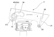
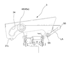
- the front and rear rocking portion 3 is provided with a pair of rail plates 31 and 31 in a plate shape and a pair of rail plates 31 disposed so as to be separated left and right so as to rock back and forth with respect to the left and right rocking portion 4.
- And 31 are provided with an upper connection plate 32 and a front connection plate 33.
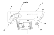
- a guide hole 34 is provided on the front side of the rail plate 31 so as to penetrate therethrough, and the guide hole 34 is a rolling element 45 provided on the side of the front end of the left and right rocking main body 42 so as to roll independently.
- the bearing 45a is engaged. What is shown with the code
- the rear end side of the rail plate 31 extends rearward and downward, and the lower end portion of a link arm LA, which is a swingable front and rear swing link, is attached to the extension end thereof via a swing shaft S5.
- the upper end portion of the arm LA is supported by the rear end portion of the left and right rocking body 4 via a rocking shaft S6. That is, the rear end portion of the front and rear rocking portion 3 is disposed in the state of being suspended so as to be able to rock back and forth in the left and right rocking portion 4 via the link arm LA.
- the guide hole 34 has a shape that gently curves forward and downward toward the front end from the rear end side, and mitigates the impact when the front and rear rocking portion 3 moves forward with the seat 5 at the rear end.
- a shockless portion SL is formed.
- the upper connection plate 32 is provided with a unit mounting hole 32a penetrating in the vertical direction, and a front and rear locking unit 8 described later with reference to FIG. 16 is attached to the unit mounting hole 32a.
- the axles of the bearing 45a which is the rolling element 45 in the illustrated example, are left and right separated. However, as long as the bearing 45a which is the rolling element 45 can roll independently on the left and right, the axle may be made common.
- the bearing 45 is relatively moved to the rear end side of the guide hole 34 at the front end and the front end of the front and rear rocking portion 3
- the link arm LA approaches a horizontal posture as well as guiding the side to a lower position
- the rear end of the front and rear rocking portion 3 is lifted to a high position. That is, the front and rear rocking portion 3 is inclined to lower the moving front end side also in the front and rear direction.
- a part is bent and a pitching damper 31c is provided on the front end side of the rail plate 31 which constitutes the front and rear rocking portion 3.
- a pitching damper 31c is provided on the front end side of the rail plate 31 which constitutes the front and rear rocking portion 3.
- the back frame 61 constituting the back 6 is attached to the rear of the upper connection plate 32 constituting the back and forth rocking body 3, and the seat outer shell 51 (see FIG. 15) constituting the seat 5 is on that Are attached to the connection plate 32. That is, when the back frame 61 supporting the backrest 62 stands up integrally behind the seat 5 and the seat 5 swings back and forth and laterally as shown by X and Y in the figure with respect to the support base 2, the back The frame 61 also moves together, but the backrest 62 of the present embodiment performs a separated operation on the back frame 61 and the seat 5 as described later.
- the back and forth movement of the seat 5 relative to the support base 2 can be suppressed by using the front and rear locking unit 8 shown in FIGS. 16 to 18 so that it can be suppressed at a predetermined position through the operation of the operation member 152 shown in FIG.
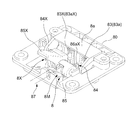
- a stopper mechanism 8M is provided, and swinging of the seat 5 relative to the support base 2 in the left-right direction can be performed in advance through the operation of the operation member 151 shown in FIG. 15 (in practice, the operation member is shared with the operation member 152).
- a left and right stopper mechanism 7M using the left and right lock unit 7 shown in FIGS. 19 and 20 is provided so as to be able to suppress at a defined position.
- the support base 2 and the left and right rocking are arranged in a layered structure in which the left and right rocking parts 4 are supported by the support base 2 and the front and rear rocking parts 3 are supported by the left and right rocking parts 4.
- a left and right stopper mechanism 7M is provided between the portions 4, and a front and rear stopper mechanism 8M is provided between the left and right rocking portion 4 and the front and rear rocking portion 3.
- the left and right stopper mechanism 7M operates the operation member 151 shown in FIG. 15 to engage or disengage the engaging portion 71 and the engaged portion 72 shown in FIG. It is to switch whether to allow or suppress the swing of the direction.
- an engagement pin 71a which is an engagement portion 71 provided on the left and right rocking portion 4 side, and a sliding surface 20 which is in relative movement with the support base 2 side which is a position opposite to the engagement pin 71a.
- the engaging pin 71a is elastically urged toward the sliding surface 20, and the engaging pin 71a is fitted into the groove 72a at a predetermined position. It is configured.
- the groove 72a has a rectangular shape in a plan view provided at the center reference position in the left-right direction of the support base 2 exposed upward through the opening 4t of the left and right rocking part 4 as shown in FIGS.
- An engaging pin 71a shown in FIG. 20 is engaged with or disengaged from the groove 72a.
- the coil spring 73a which is an elastic member 73, plays a role in urging the engagement pin 71a in the direction of projecting toward the sliding surface 20.
- the left and right stopper mechanism 7M has a conversion mechanism 74 shown in FIGS. 19 and 20 for converting the operation of the operation member 151 into an operation in the direction in which the engagement pin 71a moves away from the sliding surface 20.
- the coupling pin 71a and the coil spring 73a are integrally incorporated into the casing 70 of the left and right lock unit 7 to form a unit.
- the casing 70 has a half structure, and the engagement pin 71a has its wide portion 71aw guided by the inner surfaces of the side walls 70a and 70b of the casing 70 and is a tip from the lower end of the casing 70 It is arranged to be able to move up and down in a state where the portion 71as is protruded.
- the conversion mechanism 74 includes the coil spring 73a, which is resiliently provided in a compressed state between the upper end of the engagement pin 71a and the upper wall 70p of the casing 70, and the casing adjacent to the engagement pin 71a via the horizontal shaft 70c.
- a stopper operating arm 75 rotatably supported between side walls 70a and 70b of 70, a torsion coil spring 76 rotatably mounted together with the stopper operating arm 75, and a spherical wire tip 77a are attached to the stopper operating arm 75 And a wire tube 77 in which the tube tip 77 b is locked to the casing 70.
- the other end of the wire tube 77 is locked in the vicinity of the operation lever 151a which is the operation member 151 provided on the seat 5 as shown in FIG. 15, and the wire base end 77c drawn therefrom is connected to the operation lever 151a.
- the tip 76b of the torsion coil spring 76 is engaged with a hole 71a1 provided on the engagement pin 71a.
- the casing 70 is inserted into the unit mounting hole 42a of the swinging main body 42 constituting the left and right swinging part 4 shown in FIG. Placed on top of and screwed in place.
- the left and right side walls 70a, 70b of the casing 70 are tightly housed in the left and right side walls 42a1, 42a2 of the unit mounting hole 42a, and the engaging pin 71a is closely guided to the inner surface of the side walls 70a, 70b of the casing 70 in the casing 70. Be done. Since the engagement pin 71a is thus restrained to the left and right, the unit mounting hole 42a of the left and right swinging portion 13 shown in FIG.
- the lower opening 4t is formed of only 42a4 and has no bottom wall, and the engagement pin 71a directly hangs down from the lower opening 4t of the unit mounting hole 42a without being guided to the bottom wall. It abuts on the sliding surface 20 and is configured to engage with the groove 72a.
- the front and rear direction of the engagement pin 71a is supported by front and rear guide walls formed in the casing 70.
- the groove 72a is formed between the longitudinal ribs r1 and r1 provided in the support base 2, and a transverse rib r2 is provided around the longitudinal ribs r1 and r1 until the longitudinal rib r1 is engaged with the groove 72a.
- the upper surface of the lateral rib r2 serves as the sliding surface 20 to slide the engagement pin 71a.
- the front and rear stopper mechanism 8M can be engaged with or disengaged from the engaging portion 81 and the engaged portion 82 shown in FIG. 21 (b) by operating the operation member 152 shown in FIG. It is to switch whether to allow or suppress the swing of the direction.
- an engagement pin 81a which is an engagement portion 81 provided on the front and rear rocking portion 3 side, and a slide which is in relative movement on the side of the left and right rocking portion 4 which is the opposing position of the engagement pin 81a.
- the engaging pin 81a is resiliently urged toward the sliding face 40 while the engaging pin 81a is fitted into the groove 82a at a predetermined position. Is configured as.
- the groove 82a is, as shown in FIG.
- the coil spring 83a which is an elastic member 83, bears the role of urging the engaging pin 81a in the direction of projecting toward the sliding surface 40, and the operation of the operation member 152 is performed from the sliding surface 40 by the engaging pin 81a.
- a conversion mechanism 84 shown in FIGS. 16 and 17 for converting into movement in the direction of leaving is provided, and the conversion mechanism 84, the engagement pin 81a and the coil spring 83a are integrally incorporated in one half of the casing 80 to form a unit.
- the casing 80 is in the form of a flat saucer opened upward, and the engagement pin 81a is arranged so as to be capable of moving up and down with a portion thereof being projected from the lower end of the casing 80 while being guided by the guide 80g1 in the casing 80 There is.
- the conversion mechanism 84 includes the coil spring 83a described above resiliently compressed between the upper end of the engagement pin 81a and the cover 80a closing the upper opening of the casing 80, and the casing 80 adjacent to the engagement pin 81a.
- a stopper operating arm 85 rotatably supported by a horizontal shaft 80c bridged between side walls 80b and 80b, a torsion coil spring 86 rotatably mounted together with the stopper operating arm 85, and a spherical wire on the stopper operating arm 85 It comprises a wire tube 87 to which a tip 87a is attached and a tube tip 87b is locked to a casing 80. The other end of the wire tube 87 is locked in the vicinity of the operation lever 152a which is the operation member 152 provided on the seat 5 as shown in FIG. 15, and the wire base end 87c drawn therefrom is connected to the operation lever 152a There is.
- the tip 86a of the torsion coil spring 86 is always slidably engaged with the lower facing surface 81a1 of the engagement pin 81a.
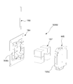
- a control mechanism 8X for automatically restraining the movement of the seat 5 in the front-rear direction at a predetermined position at the time of leaving is juxtaposed on one half of the unit 8 of the front-rear stopper mechanism 8M. ing.
- a weight receiving portion 50 (see FIG. 15) whose height position is changed by sitting on a seating surface is provided at substantially the center position of the seat 5, and the change in height position is It transmits mechanically to the control mechanism 8X shown in FIG. 16 and FIG. 18 for controlling the operation of a certain longitudinal rocking portion 3, and permits the motion of the longitudinal rocking portion 3, that is, the longitudinal movement of the seat 5 by the control mechanism 8X. It is configured to change its state between suppressions.
- the control mechanism 8X is a support portion for supporting the front and rear rocking portion 3 shown in FIG. 21 (c) provided on the front and rear rocking portion 3 which is a movable portion by a seating load.
- the engagement state of the engaged portion 82X provided on the rear surface changes to change the allowable / suppressed state of the operation of the front and rear rocking portion 3 and the operating state permitted by the elastic member 83X when the seating load disappears. Restore the original suppressed operating state.
- the engaging portion 81X and the engaged portion 82X are disengaged by the seating load, and when the seating load is lost, the engaging portion 82X is engaged by the elastic force to put the front and rear rocking portion 3 into the operation restraining state.
- the recess 82aX is configured to receive the seating load from the state in which the engaging portion 81X is fitted to the recess 82aX and to release the fitting state.
- the control mechanism 8X includes an engaging pin 81aX, which is an engaging portion 81X, and a groove-shaped concave portion 82aX, which is an engaged portion 82X provided on a sliding surface 40X that is located opposite to the engaging pin 81X.
- the engaging pin 81aX is resiliently urged toward the sliding surface 40X, and the engaging pin 81aX is configured to be fitted into the groove-like recess 82aX at a predetermined position. Then, when it is detected that the seat 5 receives a seating load at the central portion, the control mechanism 8X shown in FIGS. 16 to 17 separates the engagement pin 81aX from the groove-shaped recess 82aX.
- the coil spring 83aX which is an elastic member 83X, plays a role in urging the engaging pin 81aX in the direction of projecting toward the sliding surface 40X, and the control mechanism 8X engages the operation of the weight receiving portion 50 by seating. It has conversion mechanism 84X which converts 81aX into movement away from sliding surface 40X, and integrally incorporates conversion mechanism 84X, engagement pin 81aX and coil spring 83aX in the other half of casing 80 shown in FIG. It is unitized.
- the engagement pins 81aX are vertically movably disposed along the front and rear guides 80g2 of the casing 80 in parallel relationship with the engagement pins 81 in a flat casing 80 constituting the front and rear stopper mechanism 8M.
- the conversion mechanism 84X includes a coil spring 83aX resiliently provided in a compressed state between the upper end of the engagement pin 81aX and the cover 80a closing the upper opening of the casing 80 substantially in the same manner as the conversion mechanism 84 in part.
- the weight receiving portion 50 is a pressure receiving plate 52a rotatably fitted to and attached to the seat outer shell 51 constituting the seat 5 as shown in FIG. 15, and a convex portion 52b provided below the pressure receiving plate 52a. Is disposed at a position where the pressed portion 85xt shown in FIG. 16 displaced from the rotation center of the safety operation arm 85X can be pressed.
- the tip 86aX of the torsion coil spring 86X is smoothly and slidably engaged with the lower surface of the engagement pin 81aX at all times.
- the pressure receiving plate 52a is biased in a direction away from the safety operation arm 85X by a coil spring 52c which is an elastic body shown in FIG. As shown in FIG. 37, at the corresponding position of the seat inner shell 53, a hole 53x for avoiding interference with the pressure receiving plate 52a is provided.
- the engagement pin 81X is moved downward by the coil spring 83aX while the tip 85aX of the torsion coil spring 85X rotates with the safety operation arm 85X.
- the weight receiving portion 50 detects a weight as shown in FIG.
- the engaging pin 81X is pulled up while compressing the coil spring 83aX at the tip end 86aX of the pin, the engaging pin 81X is disengaged from the groove-like recess 82aX, and the locked state in the front-rear direction is released.
- the lock of the control mechanism 8X is released, and thereafter, whether or not the seated person locks in the front-back direction depends on the state of the front and rear fixed stopper mechanism 8M through the operation of the operation member 152
- the front and back fixed stopper mechanism 8M is not unlocked, the state is maintained, and if the front and back fixed stopper mechanism 8M is unlocked, the control mechanism 8X is operated to lock the seat 5 in front and back movement
- the seat 5 tilts at least back and forth, and when the seated person starts to move up, the seat 5 moves along with the front and rear rocking portion 3 while being inclined forward as shown in FIG.
- the engaging pin 81aX which is the engaging portion 81X shown in FIG. 21 (c) lands on the sliding surface 40X in front of the recess 82aX which is the engaged portion 82X.
- the seat 5 starts to move backward while being tilted backward due to the position of the center of gravity of the back seat due to the presence of the spine 6, and the recess 82aX in which the engaging pin 81aX which is the engaging portion 81X is the engaged portion 82X
- An action to engage in In the recess 82aX as shown in FIG. 7, grooves are connected in a perpendicular direction, and a buffer material 82z such as rubber is embedded.
- the cushioning material 82z is to prevent the engagement pin 81aX from colliding with the wall of the recess 82aX and causing impact or abnormal noise, and the engagement pin 81aX collides with the cushioning material 82z and falls into the recess 82aX. It is supposed to be.
- control mechanism 8X switches the locked state of the seat 5 at the time of leaving and sitting, so it should be called an automatic stopper mechanism at the time of leaving / seating.
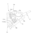
- the flange portion 31b is provided on the plate member PM of the front and rear rocking portion 3 which is the movable portion provided with the guide hole 34, ie, the vertical surface 31a of the rail plate 31
- a guide surface 31b1 for moving the bearing 45a, which is the rolling element 45, in the longitudinal direction is provided at a position extending in the horizontal direction in the lateral direction or mounting state of 31b.
- the guide surface 31b1 has a lateral dimension w1 larger than the thickness t1 of the rail plate 31 which is the plate material PM, and is integrally formed of metal together with the rail plate 31. As shown in FIG. It has a shape that makes one round around the guide hole 34 opened in the vertical surface.
- the flange portion 31 b of this embodiment is formed by plastically deforming the plate material PM around the guide hole 34, and specifically, a burring process is adopted.
- burring processing the lower hole is opened in the plate material, the periphery of the lower hole is fixed with a jig, and the edge of the lower hole is raised as a flange portion by pressing with a tool larger than the lower hole in that state.
- a cylindrical flange is formed, and it is used only at the time of tap hole processing etc., and there is no idea of guiding a rolling element so far.
- the shape of the guide hole 34 is formed in order to form a non-symmetrical hole as shown in FIG.
- a slightly smaller pilot hole 34x is opened and the periphery of the pilot hole 34x is fixed by a jig 34Z along the shape of the guide hole 34, and in that state It is pressed by a tool 34 Y which is larger than the pilot hole 34 x and corresponds to the inner peripheral shape of the guide hole 34.
- the flange portion 31b extending in the lateral direction from the longitudinal surface 31a through the R portion is formed over the entire circumference of the guide hole 34, and the laterally directed flange portion 31b is substantially formed. This is a pressure receiving area.
- the lateral dimension of the guide surface 31b1 is substantially uniform over the entire circumference.
- the selection of the processing means for the guide hole 34 was made on the condition that the guide surface 31b1 is smooth, that the guide surface 31b1 has strength, and the processing cost is low.
- the shortest distance dimension D from the guide hole 34 to the nearest end edge of the plate material PM is short in the burring process, the plate material PM is deformed by losing the load at the time of processing or at the time of processing. Therefore, as a result of attempting various tests in this embodiment, the shortest dimension D (see FIG. 28) from the guide hole 34 to the edge of the plate material PM at the appropriate position is 2 as a condition for obtaining a stable shape. In the case of a thin plate of -6 mm, it has been found that setting at least 15 mm or more is necessary and sufficient.
- the flange portion 31b formed in this manner extends outward from the pair of rail plates 31, 31 as shown in FIG.
- the guide surface 31 b 1 which is a surface, is formed on the outside of the rail plate 31.
- one end (a front end or a rear end) of the guide hole 34 is formed with a so-called shockless portion having a change in curvature radius.
- the movement speed of the seat 5 is reduced by controlling the center of gravity of the seat 5 to rise as the bearing 45a approaches the end in the operation of the seat 5.
- the flange portion 31b1 of the burring is designed to withstand the impact at this time.
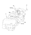
- the flange portion 31b has an upper first flange area A1 for supporting the back and forth movement of the bearing 45a which is the rolling element 45 when the seat 5 moves back and forth, and the back 6
- the second flange area A2 on the front side that supports the portion where the bearing 45a, which is the rolling element 45, reaches the front end of the guide hole 34 when turning into a closed position, and the rolling element 45 when the seated person takes a forward leaning posture.
- a bearing 45a comprising a rear third flange area A3 supporting a portion where the bearing 45a reaches the rear end of the guide hole 34, and a rolling element 45 when the left and right support states become unbalanced.
- a lower fourth flange area A4 for supporting the lower case.
- the guide hole 34 is formed on the vertical surface of the movable portion or the support portion of the chair, and moves in a state of receiving a seating load, and the movable portion is a guide by the rolling element 45 and the guide hole 34 It is supported by the support portion at two front and back locations including the structure.
- the other movable part of the chair is supported by the link arm LA, and either one of the front and rear support structure is composed of the rolling element 45 and the guide surface 31b1 described above, and the other is a different support structure.
- the embodiment consists of a link structure.
- this chair is configured by having the back 6 disposed behind the seat 5 and supporting the backrest 62 on the back frame 61 via the operating mechanism 6M.
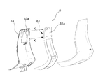
- the back inner cover 63 is attached to the back frame 61, and the back inner cover 63 is provided with an opening 63a, and the backrest 62 is operatively supported by the back frame 61 through the opening 63a. ing.
- the backrest 62 has a cushion disposed on the front of the back plate 62a and is entirely covered with tension, and the lower end of the backrest 62 is disposed at a predetermined distance above the seat surface, It is supported by the back support portion 61a at the upper end of the back frame 61 via the operating mechanism 6M.
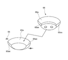
- the operating mechanism 6M is fixed to or integrally formed on the back plate 62a constituting the backrest 62, the base portion 64 having the elastic member 65 disposed on the back side, and disposed at a position adjacent to the base portion 64 and tapered on the back side. And a guide portion 66a having a convex guide portion 66a corresponding to the guide portion 65a on the front side. And the presser 66 fixed to the base portion 64 through the opening of the tilt portion 65 as shown by the arrow J in FIG. As shown by the arrow K, the opening of the back inner cover 63 is penetrated, and it pulls and fixes to the back support part 61a of the upper end side of the back frame 61 with a screw. That is, as shown in FIG.
- the presser 66 is fixed to the base portion 64 with the tilt portion 65 interposed therebetween, thereby forming a part of the base portion 64 integrally with the base portion 64, and the tilt portion Although 65 can move in the gap between the base portion 64 and the presser 66, it is necessary to compress the elastic body 67 interposed between the tilt portion 65 and the base portion 64 against elastic force. It is configured to be The elastic body 67 exerts a force on the guide portion 65 a of the tilt portion 65 in the direction of being always fitted in the guide portion 66 a of the presser 66.
- the concave guide portion 65a of the tilt portion 65 has a substantially partially oval mortar shape having at least one valley line 65ax (two in this embodiment),
- the convex guide portion 66a of the presser 66 is in the shape of a mountain having at least one ridgeline 66ax (two in this embodiment) fitted gently to it, and the valley line 65ax and the ridgeline 66ax can be fitted together Form a shape.
- the convex guide portion 66a is similar to a shape obtained by cutting a part of an elliptical sphere, and a ridgeline 66ax is formed at the intersection of the guide surface 66a and the guide surface 66a on the long axis side of the elliptical sphere.
- a valley line 65ax is also formed at a portion where the guide surface 65a and the guide surface 65a intersect at the corresponding position in the opposite concave guide portion 65a. This is because the sphere and the spherical seat do not have directionality and can not perform the positioning function.
- the convex guide portion 66a and the concave guide portion 65a are not limited to the bowl-like shape or the shape of an elliptical sphere, as long as they have a different shape that uniquely determines the directivity at the time of fitting.
- the guide portions 66a and 65a need to be formed of a smooth continuous surface.
- the ridge line 66ax and the valley line 65ax are provided to enhance the positioning function at the time of fitting.
- urethane is used for the elastic body 67, and as shown in FIG. 29, the elastic body 67 is disposed from the corner portion to the upper edge portion in the upper half of the base portion 64 having a rectangular plate shape.
- the presser 66 is attached to the base 64, the tilt unit 65 is attached to the back support 61 a of the back frame 61, and the guide 66 a of the press 66 and the guide of the tilt 65 It is set so as to be appropriately compressed in a state in which the portion 65a is fitted.
- the elastic body 67 is not provided in the lower half of the base portion 64 which has little chance of functioning in consideration of the fact that a load is applied above the center of the operation mechanism 6M when lying on the backrest 62 This does not prevent the provision of the elastic body 67 at this position.
- FIG. 33 shows a rearward tilt state when a load is applied to the upper portion of the spine 6, and FIG. 34 is a flat cross section thereof. Further, FIG. 35 shows the turning operation of the spine 6 in the case where the seated person twists the body.
- the backrest 62 is disposed in a positional relationship in which the backrest 62 is supported against the elastic reaction force in the backward direction and the turning direction while being supported by the elastic body 67, and the elastic body is
- the structure is configured such that the reaction force of the backrest 62 returning to the neutral position is increased.
- the turning direction includes turning movement in a front view right and left direction as shown in FIG. 35, and further clockwise or counterclockwise in front view.
- the guide portion 66a of the presser 66 constituting the base portion 64 and the guide portion 65a on the tilt portion 65 side are in pressure contact with the elastic member 67 and are at the reference position shown in FIG. 31 due to the shapes of the guide portions 66a and 65a. It is induced to stand still. And when pressure contact is loosened by the elastic member 67 being compressed by receiving a load from a seated person and the elastic member 67 is compressed, the guide portion 65a of the tilt portion 65 and the guide portion 66a of the presser 66 constituting the base portion 64 As shown in FIG. 33, FIG. 34, and FIG. 35, the backrest 62 moves freely at least partially apart, and the base portion 64 and the tilt portion 65 relatively change from the reference position according to the degree of pressure reception.
- the operating position is automatically returned to the neutral position of FIG. 31 in which the ridge line 66ax and the valley line 65ax coincide with each other along the guide portions 66a and 65a.
- the backrest 62 is configured such that the gap SP between the guide portions 66a and 65a expands with the backward movement with respect to the back frame 61, and as a result, the turning range in the left and right direction becomes large.
- the return reaction force when Z is removed is configured to increase according to the amount of turning movement in the left and right directions.
- the base portion 64 and the tilt portion 65 are provided with engaging portions 64b and 65b which restrict relative movement of the base portion 64 and the tilt portion 65 in cooperation with the guide portions 65a and 66a. is there.
- the base portion 64 has a standing wall 64c at the edge, and a window 64b1 to be the engaging portion 64b opens in a rectangular shape in the standing wall 64c.
- an L-shaped claw 65b1 to be the engaging portion 65b is formed at a position displaced downward on the front side.
- the base portion 64 and the tilt portion 65 are assembled with the claw 65b1 loosely fitted in the window 64b1, and the movable range of the tilt portion 65 with respect to the base portion 64 is within the range where the claw 65b1 can move in the window 64b1. It is regulated. When the range of movement is restricted, part of the backrest load is also supported at the restriction site.
- the back frame 61 and the seat 5 are viewed from the front. Although it swings integrally in the left-right direction, the backrest 62 further moves separately from the left and right turning motions of the seat 5 and the back frame 61.
- the base portion 64 is attached to the backrest 62 and the tilt portion 65 is attached to the back frame 61 side, but the base portion 64 is attached to the back frame 61 side and the tilt portion 65 is attached to the backrest 62 side It may be configured.
- this chair supports the seat 5 so as to be able to swing back and forth and right and left with respect to the support base 2.
- a seated person sitting on the chair swinging back and forth and left and right depends on the posture.
- the feeling of pressure on the thighs of the legs changes to imbalance.
- this chair is provided with a back 6 so as to be able to tilt backward at the back of the seat 5, and when the back 6 is tilted backward, the seat 5 interlocks to perform an operation of relatively raising the front and lowering the rear.
- the feeling of pressure on the thighs of the legs and the floating of the legs may cause anxiety and instability when reclining.
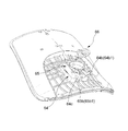
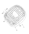
- this chair is provided with a deformation portion 5X that changes its shape in the vertical direction by receiving a seating load on the front portion 5f of the seat 5.
- the deformation portion 5X is provided at a position to receive the weight of the leg of the seat occupant, and is deformed downward when the weight of the leg is received, and returns upward when the weight of the leg is released.
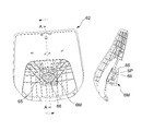
- the cushion 5 is disposed on the seat inner shell 53, and the seat 5 is covered with a stretch cloth (not shown), and the seat outer shell 51 is attached below the seat inner shell 53.
- the seat inner shell 53 is configured such that the rear portion 53a and the front portion 53b are connected by the resin hinge portion 53c, and the front portion 53b is elastically deformed with respect to the rear portion 53a at the resin hinge portion 53c. It has become. Since the cushion material 54 is also deformed along with this, these portions constitute the deformation portion 5x.
- the seat outer shell 51 is fixed to the back and forth rocking portion 3, and the rear portion 53 a of the seat inner shell 53 is attached to the upper side of the seat outer shell 51. Thereby, the deformation portion 5x including the front portion 53b of the seat inner shell 53 is deformed toward the seat outer shell 51.
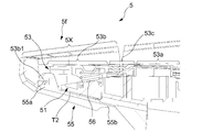
- the front seat lower cover 55 is attached to the front portion 53b which becomes the deformed portion 5x of the seat inner shell 53 so as to sandwich the seat outer shell 51.
- FIG. 15 looks as if the front lower seat cover 55 is attached to the front of the seat outer shell 51, it is not actually under the front of the seat outer shell 51 as shown in FIGS. 39 and 40.
- the front lower seat cover 55 is disposed and connected to the deformation portion 5x of the upper seat inner shell 53.
- the front seat lower cover 55 has left and right dimensions substantially corresponding to the left and right dimensions of the front portion 53b of the seat inner shell 53 as shown in FIG. It is attached to the engaged portion 53b1 (see FIGS. 39 and 40) set in the front portion 53b of the seat inner shell 53, and the rear end 55b side is shaped to extend rearward and downward along the seat outer shell 51.
- compression springs 56 which are elastic bodies, are disposed at positions compressed between the front portion 53b of the seat inner shell 53 and the like.
- the resin hinge 53c is in the form of a corrugated plate in which several lines of unevenness are connected, and the deformation portion 5x is biased in the area on the left side and the area on the right of the seat 5. According to the load, not only the vertical direction but also the torsional deformation in which one of the lateral directions of the seat 5 becomes higher than the other is easily caused.
- a fixed elbow portion 91 extending upward is attached to the elbow attachment portion 23 of the support base 2 so as to bypass the seat 5. Even if 5 swings back and forth and right and left, the fixed elbow 91 is in a fixed position that does not interfere with the seat 5. Further, a movable cover mechanism 92 in which a plurality of covers are combined is disposed below the seat 5 in order to obscure the relative movement of the front and rear rocking portion 3 and the left and right rocking portion 4 without interfering with the relative movement.
- the chair according to the present embodiment has the back 6 disposed behind the seat 5, and the back 6 is the operation mechanism 6M that supports the load received from the seated person so as to be able to pivot in the left and right directions in a front view.
- the spine 6 is free to move, and when the load is removed, the spine 6 is used as the guide portions 65a and 66a. It is configured to automatically return to the neutral position along.
- the back 6 can be turned in the left and right direction in front view, and at least a part of the guide portions 65a and 66a of the operation mechanism 6M separates and the back 6 moves freely when a load is applied. It is easy to match the various movements of the person. Further, since the spine 6 reliably returns to the neutral position along the guide portions 65a and 66a when away from the seat, the appearance of a plurality of chairs can be easily aligned when away from the seat even if the freedom of movement of the spine 6 is increased. It is possible to avoid the situation that the initial state of the chair is different each time it is done.
- the reaction force for the spine 6 to return to the neutral position is increased according to the amount of turning movement in the left and right directions, the load balance in the turning direction is easy to take, and appropriate according to the posture of the seated person It is easy to obtain a good reaction force.
- the back 6 supports the backrest 62 on the back frame 61 via the operating mechanism 6M, and the back frame 61 is erected behind the seat 5, and the backrest 62 is operated on the back frame 61.
- the operation mechanism 6M is configured only by introducing a simple pivoting mechanism or a loose uneven structure to a part of the backrest 62 since it is pivotably attached in a front view, substantially clockwise or counterclockwise via the Can.
- the back 6 supports the backrest 62 on the back frame 61 via the operating mechanism 6M, and the backrest 62 is elastic in the back direction and in the turning direction via the operating mechanism 6M having the elastic body 67. Since movement is made against the force, by applying the backrest 62 against the elastic reaction force of the elastic body 67, it is possible to apply the support force and the return force according to the size of the displacement. it can.
- the backrest 62 is configured such that the turning range in the left and right direction becomes larger along with the backward movement with respect to the back frame 61, and the turning operation in the left and right direction of the seated person It is possible to realize support that matches the movement of the body.
- the seat 5 is swingable in the left and right directions in a front view, and the back 6 is configured to perform the left and right turning operation separately from the seat 5, so that the swing of the seat 5 is performed through the posture of the seated person.
- the left and right turning motions of the backrest 62 are interlocked, and as a result, an appropriate support state can be realized according to the posture of the seat occupant.
- the operating mechanism 6M is configured by the base portion 64 and the tilt portion 65, and the guide portion 66a set on the base portion 64 side and the guide portion 65a set on the tilt portion 65 are in pressure contact with each other.
- the base portion 64 and the tilt portion 65 are moved from the reference position according to the degree of pressure reception. Since the relative change can be made, the operation mechanism 6M has a simple structure, but has a function to return to the reference position when the load is removed, and can be incorporated as an operation unit in various applications including this embodiment.
- the pressure contact of both the guide portions 66a and 65a is performed by the elastic body 67, and when the elastic body 67 is compressed by pressure receiving, the guide portion 65a of the tilt portion 65 and the guide portion 66a of the base portion 64 are separated.
- the elastic body 67 can play the role of flexibly receiving the backrest load and the role of returning the guide portions 66a and 65a to the reference position.
- the operating mechanism 6M also has a base portion 64 fixed to the backrest 62 and having the elastic body 67 disposed on the back side, and a guide portion 65a disposed at a position adjacent to the base portion 64 and recessed on the back side.
- the tilt portion 65 is opened at its bottom side, and has a convex guide portion 66a corresponding to the guide portion 65a on the front side, with the guide portion 66a fitted in the guide portion 65a through the opening of the tilt portion 65
- the presser 66 fixed to the base portion 64, and the tilt portion 65 is fixed to the back support portion 61a provided at the upper end portion of the back frame 61, so that a structure easy to assemble is realized can do.
- one of the guide portions 65a is substantially partially in the shape of an oval mortar having at least one valley line 65ax, and the other guide portion 66a has a chevron shape having at least one ridgeline 66ax gently fitted thereto.
- the positioning function at the reference position can be enhanced by providing a structure in which the valley line 65ax and the ridge line 66ax can be fitted.
- the base portion 64 and the tilt portion 65 are provided with engaging portions 64b and 65b which cooperate with the guide portions 66a and 65a to restrict the relative movement of the base portion 64 and the tilt portion 65, and these engagements are performed. Since a part of the backrest load is supported by the portions 64b and 65b, it is possible to prevent local loads from being concentrated on the guide portions 6a and 65a.
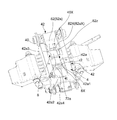
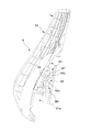
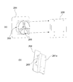
- the chair shown in FIG. 41, FIG. 42, and FIG. 43 has an operation mechanism 106M different from that of the above-described embodiment on the back in order to support the load received from the seat occupant in a pivoting manner in the left and right directions. Also when the load is applied, at least a part of the guide portions 165a and 166a of the motion mechanism is separated and the back moves freely, and the motion position of the motion mechanism 106M is removed when the load is removed. Are automatically returned to the neutral position along the guide portions 165a and 166a of the operation mechanism 106M.
- the operation mechanism 106M is constituted by the base portion 164 and the tilt portion 165, and the guide portion 166a set on the base portion 164 side and the guide portion 165a set on the tilt portion 165 side are pressed against each other
- the base portion 164 and the tilt portion 165 have a reference position which is guided by the shapes of the guide portions 166a and 165a to stand still, and the pressure contact is loosened by the pressure received from the seated person.
- the function of relative change from the reference position is also the same as in the above embodiment.
- the shape of the guide portions 166a and 165a is different from that of the above embodiment, and one guide portion 166a is a shaft-like portion 166 which is bridged vertically and horizontally, and the other guide portion 165a is vertically Alternatively, a V-shaped groove for guiding the left and right shaft members 166 to a central position, and a semicircular groove bottom 165a1 defining a reference position is formed at the center of the groove.
- the tilt portion 165 can move in the gap between the base portion 164 and the shaft-like member 166, but when floating, the elastic portion 167 interposed between the tilt portion 265 and the base portion 164 is compressed against the elastic force. It is configured to be necessary.
- the shaft-like member 166 is divided and disposed at a position avoiding the elastic body 167, and held at that position by the support members 164b and 165b. Even in this way, the operating mechanism can be realized simply.
- the V groove is formed in a part of the window 164b1 serving as the engaging portion, and relative operation is enabled within a range in which a portion of the shaft-like portion 166 serving as the engaging portion is restricted by the window 164b1. Therefore, it can be said that the base portion 164 and the tilt portion 165 are provided with an engagement portion which regulates the relative movement of the base portion 164 and the tilt portion 165 in cooperation with the guide portions 165a and 166a. Since a part of the back load is supported by the engaging portion, concentration of local load on the guide portion can be prevented.
- the back 6 can be pivoted in the left and right direction in front view, and the back 6 is separated from the seat 5 and turned left and right A configuration to operate is realized.
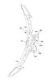
- the back 6 is disposed behind the seat, and the operation mechanism 206M supporting the load received from the seated person so as to be able to pivotally move in the lateral direction in a front view
- the operation mechanism 206M supporting the load received from the seated person so as to be able to pivotally move in the lateral direction in a front view
- the seat can swing in the left-right direction in a front view, and the spine 6 is separated from the seat to perform a left-right turning operation.
- the operation mechanism 206M is configured by the base portion 264, the tilt portion 265, and the back frame pressure receiving portion 261a on the upper end side of the back frame 261, and the first guide set on the base portion 264 side
- the first guide portion 265a1 set on the side of the portion 266a1 and the tilt portion 265 is in pressure contact with each other
- the second guide portion 266a2 set on the side of the base portion 264 and the second guide portion 265a2 of the back frame pressure receiving portion 261a are in pressure contact with each other
- the operating mechanism 206M is fixed to or integrally formed on a back plate constituting a backrest, and a base portion 264 provided with a presser 266 in a protruding state on the back side, and is disposed at a position adjacent to the base portion 264
- the first guide portion 265a1 having a tapered shape is disposed at a position facing the tilt portion 265 with the press tool 266 interposed between the tilt portion 265 having its center opened in the front-rear direction, and the surface is concavely tapered on the front side
- a convex frame corresponding to the first guide portion 265a1 and the second guide portion 265a2 on the front side or the back side is formed of the back frame pressure receiving portion 261a having the second guide portion 265a2.
- a first guide portion 266a1 and a second guide portion 266a2 are provided.
- the presser member 266 is fixed to the base portion 264 through the opening of the tilt portion 265 as shown by the arrow J1 in FIGS. 44 and 45, and the tilt portion 265 is a back frame constituting the spine 206 as shown by the arrow K1. It is pulled and fixed to the back support part 261a of the upper end side of 261 with a screw.
- the first elastic body 267a1 is interposed between the presser 266 and the back frame pressure receiving portion 261a
- the second elastic body 267a2 is interposed between the presser 266 and the tilt portion 265, respectively.
- the pressing tool 266 is fixed to the base section 264 with the tilt section 265 interposed therebetween, thereby forming a part of the base section 264 integrally with the base section 264, and the pressing tool 266 has a height with the base section 264 It is possible to move in the gap of the frame pressure receiving portion 261a, but when moving, it is possible to compress the elastic portion 267 interposed between the tilt portion 265 and the back frame pressure receiving portion 261a and the pressing tool 266 against elastic force. It is configured to be necessary.
- the guide portion 266a1 of the pressing member 266 is always fitted to the guide portion 265a1 of the tilt portion 265 by the elastic body 267a1, and the guide portion 266a2 of the pressing member 266 is always fitted to the guide portion 265a2 of the back frame pressure receiving portion 261a by the elastic body 267a2.
- the power of the direction is working.
- the first guide portion 266a1 and the second guide portion 266a2 of the presser member 266 are composed of three projecting portions similar to the wing of a propeller, and the first guide portion 265a1 on the tilt portion 265 side receiving the same
- the second guide portion 265a2 on the side 261a is in the form of a notch for receiving a part of the three projections.
- the guide portions 266a1 and 266a2 have a bent line portion which is convex, and the guide portions 265a1 and 265a2 have a notch shape having a valley line portion.
- the presser 266 on the base 264 side compresses the first and second elastic members 267a1 and 267a2, while the first guide 266a1 on the base 264 side is the first guide 265a1 on the tilt side.
- the second guide portion 266a2 on the side of the base portion 264 separates from the second guide portion 265a2 on the side of the back frame pressure receiving portion 261a, so that the base portion 264 can freely move together with the pressing portion 266, and the load is removed.
- the first elastic member 267a1 and the second elastic member 267a2 press the holding member 266 against the tilt portion 265 and the back frame pressure receiving portion 261a, and the first guide portion 266a1 and the second guide portion 265a1 and the second guide portion 266a2 and the second guide Since the portion 265a2 is engaged, the spine returns to the reference position.
- the support structure is effective for the behavior of the spine 6 in which the upper edge of the backrest moves backward or forward and the lower edge moves forward or backward.
- the chair of the present invention has the configuration described above. It is possible to use especially suitably in an office etc.
Landscapes
- Chairs For Special Purposes, Such As Reclining Chairs (AREA)
- Chairs Characterized By Structure (AREA)
- Chair Legs, Seat Parts, And Backrests (AREA)
Abstract
Taking into account the diverse movements of a seated person, the purpose of the present invention is to realize a chair that can cause a back thereof to make a novel motion to counterbalance a lateral motion of a seat when a lateral rocking motion in a form not seen in the prior art is applied to the seat, and that can return to a prescribed position when the seated person leaves the seat. Accordingly, the present invention is configured such that a back (6) is disposed behind a seat (5), and the back (6) is provided with a movement mechanism (6M) that supports a load received from a seated person such that the back (6) can rotate in the lateral direction when viewed from the front. When a load is applied, guide parts (65a, 66a) of the movement mechanism (6M) separate at least partly, thereby allowing the back (6) to move freely, and when the load is removed, the back (6) is made to automatically return along the guide parts (65a, 66a) to a neutral position.
Description
本発明は、オフィス等において好適に利用される椅子に関するものである。
The present invention relates to a chair suitably used in an office or the like.
着座者の体勢変化に合わせて背凭れが向きや角度を変える椅子が従来から存在している(例えば、特許文献1~5)。
There have conventionally been chairs that change the direction and angle of the backrest in accordance with the change in posture of a seated person (eg, Patent Documents 1 to 5).
特許文献1の椅子は、一対の背板がそれぞれゴム部品を介してフレームに取り付けられ、上下に回動するとともに、左右にはゴム部品を圧縮しながら反発力を蓄えつつ向きを変えるように構成されている。
The chair of Patent Document 1 is configured such that a pair of back plates are respectively attached to the frame via rubber parts, turn up and down, store the repulsive force while changing the direction while compressing the rubber parts to the left and right It is done.
特許文献2の椅子は、自動車シートの背の上半分が、縦軸の回りに反発力を蓄積しながら回転するように構成されている。
The chair of Patent Document 2 is configured such that the upper half of the back of a car seat rotates around a longitudinal axis while accumulating repulsive force.
特許文献3の椅子は、背座一体に構成されたもので、座下部が支点回りにローリング可能に支持され、背座がローリングする際に座下部の周囲に配置したゴム部品を圧縮して、背座が基準位置に戻る反発力を生じるように構成されている。
The chair of Patent Document 3 is configured integrally with a back seat, and the lower part of the seat is supported to be able to roll around a fulcrum, and when the back seat rolls, the rubber parts arranged around the lower part are compressed, The back seat is configured to generate a repulsive force returning to the reference position.
特許文献4の椅子は、背座一体に構成されたもので、背の一部が支点で固定されており、この支点を中心に、着座者の動きに合わせて背座がそれ自体の弾性によって正面視左右にねじれるように変形する構成が開示されている。
The chair of Patent Document 4 is configured integrally with a back seat, and a part of the back is fixed at a fulcrum, and the back seat is elastic by its own elasticity according to the movement of a seated person around this fulcrum A configuration is disclosed that deforms so as to twist in a front view left and right.
特許文献5の椅子は、背座が複数の区画に分けられて区画間には一部に変形し易く一部が分離されており、区画間がねじれ易く変形自由度が高くなるように構成されている。
The chair of Patent Document 5 is configured such that the back seat is divided into a plurality of sections and the sections are easily deformed in part and partially separated, and the sections are easily twisted and the degree of deformation is high. ing.
ところで、座面で長時間同じ姿勢を維持することは苦痛であり、利用者が無意識のうちに体勢を変えながら着座を続けている。この体勢の変更には、臀部や大腿部の圧迫を避けるために左右負担の割合を変えるべく、下半身、特に臀部の左右一方が上がり他方が下がるように体をねじる動作を伴い、このとき上半身はバランスをとって反対方向に動くのが自然である。これを正面から見れば、背の左右旋回動作を伴う。
By the way, it is painful to maintain the same posture for a long time on the seat surface, and the user keeps sitting while changing his posture unconsciously. In order to avoid compression of the buttocks and thighs, this change in posture involves an action of twisting the body so that the lower body, in particular one of the buttocks, rises and the other falls, in order to change the ratio of left and right strain. It is natural to balance and move in the opposite direction. If this is seen from the front, it will be accompanied by the left and right turning motion of the spine.
しかしながら、特許文献1、2の椅子は、縦軸回りの回転動作に過ぎないため、背の動きが上記のような着座者の動きに合わず、適切なサポートが難しいものである。
However, since the chairs of Patent Documents 1 and 2 are merely rotational operations about the vertical axis, the motion of the back does not match the motion of the seated person as described above, and appropriate support is difficult.
一方、特許文献3のものは背座ともに旋回動作はするものの、背座が同方向に大きく傾いてしまうため、着座者のバランスが崩れ、立て直しも難しいものである。
On the other hand, in the case of Patent Document 3, although the back seat performs turning motion, the back seat is largely inclined in the same direction, so the balance of the seated person is lost, and it is difficult to remake.
また、特許文献4の椅子は、背が支点回りにねじれるように回転動作し、これに座の変形が伴うものであるため、下半身の動きと上半身の動きを考えた場合、必ずしも着座者の背の動きに合致しているとは言い難い。
Further, the chair of Patent Document 4 rotates so that the back twists about the fulcrum, and this is accompanied by the deformation of the seat. Therefore, when considering the lower body movement and the upper body movement, the back of the seated person is not necessarily required. It is hard to say that it matches the movement of
さらに、特許文献5の椅子は、変形自由度が高い反面、元に戻ろうとする反発力が不十分になり易く、サポート力が乏しいものとなってしまう。
Furthermore, while the chair of Patent Document 5 has a high degree of freedom of deformation, the repulsive force to return to the original tends to be insufficient, and the support power becomes poor.
特に、着座者の多様な動きに鑑みて、座に従来にはない前後左右の揺動動作を与えることを追求する場合、座の左右の動きに対して背がこれに見合う新たな動作を行う必要がある。
In particular, when seeking to give the seat unconventional front-back, left-right, and left-right rocking motion in view of the various movements of the seat occupant, the back performs a new movement commensurate with the left-right movement of the seat. There is a need.
本発明は、これらの課題に着目し、着座者の多様な動きに鑑みて、座に従来にはない態様で左右の揺動動作を与えるにあたり、座の左右の動きに対して背にこれに見合う新たな動作を行うことができ、離席時には所定位置に復帰することができる椅子を実現することを目的としている。
The present invention pays attention to these problems, and in view of the various movements of the seat occupant, when giving the seat the left and right rocking motion in a non-conventional manner, the back to the left and right movements of the seat An object of the present invention is to realize a chair that can perform a corresponding new operation and can return to a predetermined position when the user is away.
本発明は、かかる目的を達成するために、次のような手段を講じたものである。
The present invention takes the following means in order to achieve such an object.
すなわち、本発明の椅子は、座の後方に背が配置されたもので、着座者から受ける荷重を正面視左右方向に旋回移動可能に支持する動作機構を背に備え、荷重が掛かると少なくとも動作機構のガイド部の一部が離れて背が自由に動く状態になり、荷重が取り去られた際に、背をガイド部に沿って自動的に中立位置に復帰させるように構成されることを特徴とする。
That is, the chair according to the present invention has a back disposed at the rear of the seat and has an operating mechanism for supporting the load received from the seated person so as to be able to pivotly move in the left and right directions in a front view. A part of the guide part of the mechanism is separated and the back is free to move, and it is configured to automatically return the back to the neutral position along the guide when the load is removed. It features.
このように構成すると、背が正面視において左右方向への旋回動作が可能で、荷重が掛かると少なくとも動作機構のガイド部の一部が離れて背が自由に動く状態になるため、着座者の多様な動きに合わせ易い。また、離席時には背がガイド部に沿って中立位置に確実に復帰するため、背の動きの自由度を高めても離席時に複数の椅子の外観が揃い易く、また着座する度に椅子の初期状態が違うという事態を回避することができる。
With such a configuration, the back can be turned in the left and right direction in front view, and at least a part of the guide portion of the operation mechanism is separated when the load is applied, and the back freely moves. Easy to adjust to various movements. In addition, since the back of the seat returns to the neutral position reliably along the guide part, the appearance of a plurality of chairs can be easily aligned at the time of leaving the seat even if the freedom of back movement is increased, and each time the chair is seated It is possible to avoid a situation where the initial state is different.
旋回方向への荷重バランスを考慮した場合、左右両方向への旋回移動量に応じて背が中立位置に戻る反力が大きくなるように構成されていることが望ましい。
When the load balance in the turning direction is taken into consideration, it is preferable that the reaction force in which the spine returns to the neutral position becomes large according to the turning movement amount in the left and right directions.
動作機構を簡単に組み込むためには、前記背を、背フレームに前記動作機構を介して背凭れを支持させた構造とし、前記背フレームが座の後方に立設され、前記背凭れが前記背フレームに前記動作機構を介して正面視、略時計回り又は反時計回りに旋回可能に取り付けられていることが望ましい。
In order to easily incorporate an operating mechanism, the back is configured to support a backrest on the back frame via the operating mechanism, the back frame is erected behind a seat, and the backrest is the back. It is desirable that the frame be pivotally mounted in a front view, substantially clockwise or counterclockwise direction through the operation mechanism.
適切なサポート力と復帰力を実現するためには、前記背は、背フレームに前記動作機構を介して背凭れを支持させたものとし、背凭れは、弾性体を有する前記動作機構を介して後方向及び旋回方向に弾性反力に抗して移動するように構成することが望ましい。
In order to realize an appropriate supporting force and restoring force, the back is made to support the backrest by the back frame via the operation mechanism, and the backrest is through the operation mechanism having an elastic body. It is desirable to be configured to move against the elastic reaction force in the backward direction and in the turning direction.
体の動きに合致したサポートを実現するためには、前記背凭れは、前記背フレームに対する後方向の移動に伴って左右方向への旋回範囲が大きくなるように構成されることが望ましい。
Preferably, the backrest is configured such that the range of turning in the left and right direction increases as the back movement with respect to the back frame is realized in order to realize the support matched to the movement of the body.
着座者の体勢に応じた適切なサポート状態を実現するためには、座は正面視左右方向に揺動可能であり、背は座とは切り離して左右旋回動作を行うように構成されていることが望ましい。
In order to realize an appropriate support state according to the seated person's posture, the seat can be pivoted in the left and right directions as viewed from the front, and the back is separated from the seat and configured to perform left-right turning operation. Is desirable.
色々な用途に動作ユニットとして組み込むためには、前記動作機構が、ベース部と、チルト部とによって構成され、ベース部側に設定したガイド部とチルト部側に設定したガイド部を互いに圧接することでそのガイド部同士の形状によって誘導されて静止する基準位置を有し、着座者からの受圧によって前記圧接が緩んだ場合、受圧の程度に応じて前記ベース部と前記チルト部が基準位置から相対変化し得ることが望ましい。
In order to be incorporated as an operation unit in various applications, the operation mechanism is constituted by a base portion and a tilt portion, and the guide portion set on the base portion side and the guide portion set on the tilt portion side are in pressure contact with each other. When the pressure contact is loosened due to the pressure received from the seat occupant, the base and the tilt relative to the reference position according to the degree of pressure reception. It is desirable to be able to change.
背凭れ荷重の支持と基準位置への復帰を適切に行うためには、両ガイド部の圧接は弾性体で行い、受圧で弾性体が圧縮されることにより、チルト部のガイド部とベース部のガイド部が離反するように構成されていることが望ましい。
In order to properly support the back load and return to the reference position, the pressure contact between the two guides is performed with an elastic body, and the elastic body is compressed by pressure reception, so that the guide portion of the tilt portion and the base portion It is desirable that the guide portions be configured to be separated.
組み付け容易とするためには、動作機構は、背凭れに固定され背面側に弾性体を配置したベース部と、このベース部に隣接する位置に配置されて背面側にテーパ状に凹むガイド部を有しその底部側が開口したチルト部と、前面側に前記ガイド部に対応する凸状のガイド部を有しそのガイド部が前記ガイド部に嵌め込まれた状態で前記チルト部の開口を介して前記ベース部に固定される押え具とを備え、前記チルト部を背フレームの上端部に設けた受圧部に固定することにより構成されていることが望ましい。
In order to facilitate assembly, the operation mechanism includes a base portion fixed to the backrest and having an elastic body disposed on the back side, and a guide portion disposed at a position adjacent to the base portion and recessed on the back side. Has a tilt portion having a bottom portion side open, and a convex guide portion corresponding to the guide portion on the front side with the guide portion fitted in the guide portion via the opening of the tilt portion It is preferable that the apparatus further comprises a pressing tool fixed to the base portion, and the tilt portion be fixed to a pressure receiving portion provided at an upper end portion of the back frame.
基準位置での位置決め機能を高めるためには、一方のガイド部は少なくとも1つの谷線を有するほぼ部分的に楕円すり鉢状であり、他方のガイド部はそれに緩やかに嵌り合う少なくとも1つの稜線を有する山形をなしており、前記谷線と稜線が嵌り合うことが可能としておくことが望ましい。
In order to enhance the positioning function at the reference position, one of the guide portions is substantially partially oval-shaped with at least one valley and the other guide portion has at least one ridge that gently fits into it It is desirable that it has a chevron shape, and that the valley line and the ridge line can be fitted.
簡易に動作機構を実現する他の構成としては、両ガイド部のうち一方のガイド部は、上下又は左右に架け渡された軸状部であり、他方のガイド部は、上下又は左右の軸状部材を中央位置に導くV溝であるものが挙げられる。
As another configuration for realizing the operation mechanism simply, one of the two guide portions is a shaft-like portion bridged vertically and horizontally, and the other guide portion is vertically and horizontally axially shaped What is a V groove which guides a member to a central position is mentioned.
ガイド部に局所荷重が集中することを防止するためには、ベース部及びチルト部に、ガイド部と共働してベース部及びチルト部の相対移動を規制する係合部が設けてあることが望ましい。
In order to prevent local loads from concentrating on the guide part, the base part and the tilt part should be provided with an engagement part which regulates the relative movement of the base part and the tilt part in cooperation with the guide part. desirable.
背凭れの上縁が後方又は後方へ移動し下縁が前方又は後方へ移動するような背の挙動に有効に対応するためには、一方のガイド部は3つの突出部からなり、他方のガイド部は前記3つの突出部を受け入れる形状をなし、前記一方と他方のガイド部の間に弾性体が配置されていることが望ましい。
In order to effectively correspond to the behavior of the back such that the upper edge of the backrest moves backward or backward and the lower edge moves forward or backward, one of the guide parts consists of three projections, the other guide Preferably, the portion is shaped to receive the three protrusions, and an elastic body is disposed between the one and the other guide portions.
本発明によれば、着座者の多様な動きに鑑みて、座に従来にはない態様で左右の揺動動作を与えるにあたり、座の左右の動きに対して背にこれに見合う新たな動作を行うことができ、離席時には所定位置に復帰することができる、新たな椅子を提供することが可能となる。
According to the present invention, in view of the various movements of the seat occupant, when giving the seat the left and right rocking motion in an unconventional manner, a new motion commensurate with the back and forth motion of the seat is provided. It is possible to provide a new chair that can be performed and returned to a predetermined position when away from the seat.
以下、本発明の一実施形態を、図面を参照して説明する。
Hereinafter, an embodiment of the present invention will be described with reference to the drawings.
この椅子は、図1~図5に示すように、キャスター11に支持された脚羽根12の中心部に昇降機構を内設した脚支柱13を立設し、この脚支柱13の上端側に支持基部2を回転可能に取り付けることによって構成される事務用椅子である。支持基部2には交差する2方向である前後方向(図中X方向)および左右方向(図中Y方向)の何れか一方向に動作可能な一方向動作部(可動部)としての前後揺動部3、および、前後左右何れか他方向に動作可能な他方向動作部(支持部)である左右揺動部4を介して、可動部である座5が支持され、座5は支持基部2に対して前後左右に揺動可能とされる。具体的には、座5と座5を支持する支持基部2の間に前後揺動部3が設けられ、前後揺動部3と支持基部2の間に左右揺動部4が設けられている。座5の後方には背6が配置されている。
In this chair, as shown in FIGS. 1 to 5, a leg post 13 having a lifting mechanism installed therein is erected at the center of a leg blade 12 supported by a caster 11, and supported at the upper end side of the leg post 13 It is an office chair configured by rotatably mounting the base 2. Back and forth rocking as a one-way operation part (movable part) operable in any one of the longitudinal direction (X direction in the figure) and the left and right direction (Y direction in the figure) which are two directions intersecting the support base 2 The seat 5 which is a movable portion is supported via the portion 3 and the left and right swinging portion 4 which is another direction operating portion (supporting portion) operable in any of the front and rear, left and right directions. It is possible to swing back and forth and right and left. Specifically, the front and rear rocking portion 3 is provided between the seat 5 and the support base 2 supporting the seat 5, and the left and right rocking portion 4 is provided between the front and rear rocking portion 3 and the support base 2 . Behind the seat 5, a spine 6 is disposed.
支持基部2は、着座者の荷重を受ける構造体としての役割を担うもので、支柱13の上端が挿入される上下方向の貫通孔21aを有する支基本体21の左右両側に軸受ベース部22を介して左右一対の肘取付部23が一体に成形されている。支基本体21の前後方向の面に開口する孔21aには軸揺れダンパー21bが取り付けられ、軸受ベース部22の前後面に開口する孔22aには左右揺動リンクL1、L2の上端部が揺動支軸S1、S2を介して取り付けられている。
The support base 2 plays a role as a structure to receive the load of the seat occupant, and the bearing base portions 22 are provided on the left and right sides of the support basic body 21 having through holes 21a in the vertical direction into which the upper ends of the columns 13 are inserted. The pair of left and right elbow attachment portions 23 are integrally formed via the two. The shaft swing damper 21b is attached to the hole 21a opened in the front and rear direction surface of the support basic body 21, and the upper end portions of the left and right swing links L1 and L2 swing in the hole 22a opened in the front and rear surface of the bearing base portion 22. It is attached via the movable support shafts S1 and S2.
左右揺動部4は、支持基部2に対して左右に揺動動作を行うべく、前後に離間させて配置される板状をなす一対のリンクベース41と、これら一対のリンクベース41、41間を接続する左右揺動本体42とを備えたもので、リンクベース41の左右両端部には孔41a、41aが開口し、左右揺動リンクL1、L2の下端部が揺動軸S3、S4を介して取り付けられる。図4はリンクL1、L2を揺動軸S1~S4を介して取り付けた状態を示している。左右揺動本体42には図7及び図8に示すように上下方向に貫通するユニット取付孔42aが設けられ、このユニット取付孔42aに後述する左右ロックユニット7が取り付けられている。すなわち、左右揺動本体42は左右揺動リンクL1、L2を介して支持基部2に左右揺動可能に吊り下げた状態に配され、左右揺動リンクL1、L2は図4等に示すように上端間の距離よりも下端間の距離が小さくなる状態で取り付けられている。
The left and right rocking portion 4 is provided with a pair of plate-like link bases 41 which are disposed to be separated in the front and rear direction so as to perform a rocking operation to the left and right with respect to the support base 2. The left and right end portions of the link base 41 are provided with holes 41a and 41a, and the lower end portions of the left and right swing links L1 and L2 are provided with the swing shafts S3 and S4. It is attached through. FIG. 4 shows a state in which the links L1 and L2 are attached via the swing axes S1 to S4. As shown in FIGS. 7 and 8, the left and right rocking main body 42 is provided with a unit attachment hole 42a penetrating in the vertical direction, and a left and right lock unit 7 described later is attached to the unit attachment hole 42a. That is, the left and right rocking main body 42 is disposed so as to be able to rock horizontally from the support base 2 via the left and right rocking links L1 and L2, and the left and right rocking links L1 and L2 are as shown in FIG. It is attached in a state in which the distance between the lower ends is smaller than the distance between the upper ends.
すなわち、左右揺動部4が揺動するときは、図9~図10に示すように揺動先に位置するリンクL2(L1)が鉛直姿勢に近づき、もう一方のリンクL1(L2)が水平姿勢に近づく結果、移動先端側がより低くなるように傾斜しつつ、当該左右揺動部4の重心が持ち上がる動作を行う。
That is, when the left and right rocking portion 4 is rocked, as shown in FIGS. 9 to 10, the link L2 (L1) located at the rocking destination approaches the vertical posture, and the other link L1 (L2) is horizontal As a result of approaching the posture, an operation of raising the center of gravity of the left and right rocking portion 4 is performed while inclining so that the moving front end side becomes lower.
リンクベース41の中央部には窓41cが開口しており、この窓41c内に横揺れダンパー44が位置づけられて、横揺れダンパー44が窓41c内で相対移動し得る範囲に、左右揺動部4の揺動範囲が規制されている。
A window 41c is opened at the central portion of the link base 41, and the rolling damper 44 is positioned in the window 41c, so that the rolling damper 44 can move relative to the window 41c. The swing range of 4 is restricted.
前後揺動部3は、左右揺動部4に対して前後に揺動動作を行うべく、左右に離間させて配置される板状をなす一対のレールプレート31、31と、一対のレールプレート31、31間を接続する上接続板32及び前接続板33を備える。レールプレート31の前側にはガイド孔34が貫通させて設けてあり、このガイド孔34に、左右揺動本体42の前端側の側面に左右独立して転動可能に設けた転動体45であるベアリング45aが係合される。図中符号45zで示すものは、レールプレート31の内面側に配置されてベアリング45aよりも径の大きいスペーサである。レールプレート31の後端側は後下方に延びて、その延出端に揺動軸S5を介して揺動可能な前後揺動リンクであるリンクアームLAの下端部が取り付けられており、このリンクアームLAの上端部は左右揺動体4の後端部に揺動軸S6を介して支持される。すなわち、前後揺動部3の後端部はリンクアームLAを介して左右揺動部4に前後揺動可能に吊り下げられた状態に配されている。ガイド孔34は後端側から前端側に向かうほど前下方に緩やかに湾曲する形状をなしており、後端部には座5とともに前後揺動部3が前方へ移動した際の衝撃を緩和するショックレス部SLが形成されている。上接続板32には上下方向に貫通するユニット取付孔32aが設けられ、このユニット取付孔32aに図16に基づいて後述する前後ロックユニット8が取り付けられる。図示例では転動体45であるベアリング45aの車軸は左右分離している。ただし、転動体45であるベアリング45aが左右独立して転動可能であれば、車軸は共通化してもよい。
The front and rear rocking portion 3 is provided with a pair of rail plates 31 and 31 in a plate shape and a pair of rail plates 31 disposed so as to be separated left and right so as to rock back and forth with respect to the left and right rocking portion 4. , And 31 are provided with an upper connection plate 32 and a front connection plate 33. A guide hole 34 is provided on the front side of the rail plate 31 so as to penetrate therethrough, and the guide hole 34 is a rolling element 45 provided on the side of the front end of the left and right rocking main body 42 so as to roll independently. The bearing 45a is engaged. What is shown with the code | symbol 45z in the figure is a spacer arrange | positioned at the inner surface side of the rail plate 31, and larger diameter than the bearing 45a. The rear end side of the rail plate 31 extends rearward and downward, and the lower end portion of a link arm LA, which is a swingable front and rear swing link, is attached to the extension end thereof via a swing shaft S5. The upper end portion of the arm LA is supported by the rear end portion of the left and right rocking body 4 via a rocking shaft S6. That is, the rear end portion of the front and rear rocking portion 3 is disposed in the state of being suspended so as to be able to rock back and forth in the left and right rocking portion 4 via the link arm LA. The guide hole 34 has a shape that gently curves forward and downward toward the front end from the rear end side, and mitigates the impact when the front and rear rocking portion 3 moves forward with the seat 5 at the rear end. A shockless portion SL is formed. The upper connection plate 32 is provided with a unit mounting hole 32a penetrating in the vertical direction, and a front and rear locking unit 8 described later with reference to FIG. 16 is attached to the unit mounting hole 32a. The axles of the bearing 45a, which is the rolling element 45 in the illustrated example, are left and right separated. However, as long as the bearing 45a which is the rolling element 45 can roll independently on the left and right, the axle may be made common.
すなわち、前後揺動部3の上面が略水平姿勢をとる図11の状態から、前後揺動部3が図12に示すように後方へ移動すると、前端部のガイド孔34の前端側にベアリング45aが相対移動して前後揺動部3の前端側が高い位置に持ち上げられるとともに、リンクアームLAが垂直姿勢に近づく結果、前後揺動部3の後端側が低い位置に導かれる動作を行う。逆に、図11の状態から前後揺動部3が図13に示すように前方へ移動すると、前端部のガイド孔34の後端側にベアリング45が相対移動して前後揺動部3の前端側を低い位置に導くとともに、リンクアームLAが水平姿勢に近づく結果、前後揺動部3の後端部が高い位置に持ち上げられる動作を行う。すなわち、前後揺動部3は前後方向に対しても移動先端側がより低くなるように傾斜する動作を行う。
That is, when the front and rear rocking portion 3 moves backward as shown in FIG. 12 from the state of FIG. 11 in which the upper surface of the front and rear rocking portion 3 takes a substantially horizontal posture, the bearing 45a on the front end side of the guide hole 34 at the front end. As a result, the front end side of the front and rear rocking portion 3 is lifted to a high position, and as a result of the link arm LA approaching a vertical posture, the rear end side of the front and rear rocking portion 3 is guided to a low position. Conversely, when the front and rear rocking portion 3 is moved forward as shown in FIG. 13 from the state of FIG. 11, the bearing 45 is relatively moved to the rear end side of the guide hole 34 at the front end and the front end of the front and rear rocking portion 3 As the link arm LA approaches a horizontal posture as well as guiding the side to a lower position, the rear end of the front and rear rocking portion 3 is lifted to a high position. That is, the front and rear rocking portion 3 is inclined to lower the moving front end side also in the front and rear direction.
前後揺動部3を構成するレールプレート31の前端側には、一部を折り曲げて縦揺れダンパー31cが設けられ、前後揺動部3が後方へ揺動したときに揺動端近傍で左右揺動部4の前端下部4z(図3参照)に当接して、後方移動端でのショックが緩和される。
A part is bent and a pitching damper 31c is provided on the front end side of the rail plate 31 which constitutes the front and rear rocking portion 3. When the front and rear rocking portion 3 is rocked backward, the rocking is performed near the rocking end. By abutting on the front lower end 4z (see FIG. 3) of the moving part 4, the shock at the rear moving end is relieved.
図14に示すように、背6を構成する背フレーム61は前後揺動体3を構成する上接続板32の後部に取り付けられ、座5を構成する座アウターシェル51(図15参照)はその上から接続板32に取り付けられる。すなわち、座5の後方に背凭れ62を支持する背フレーム61が一体に起立し、座5が支持基部2に対して図中X、Yに示すように前後・左右方向に揺動すると、背フレーム61も一緒になって移動するが、本実施形態の背凭れ62は後述のように背フレーム61や座5に対して切り離した動作を行う。
As shown in FIG. 14, the back frame 61 constituting the back 6 is attached to the rear of the upper connection plate 32 constituting the back and forth rocking body 3, and the seat outer shell 51 (see FIG. 15) constituting the seat 5 is on that Are attached to the connection plate 32. That is, when the back frame 61 supporting the backrest 62 stands up integrally behind the seat 5 and the seat 5 swings back and forth and laterally as shown by X and Y in the figure with respect to the support base 2, the back The frame 61 also moves together, but the backrest 62 of the present embodiment performs a separated operation on the back frame 61 and the seat 5 as described later.
支持基部2に対する座5の前後方向の揺動については、図15に示す操作部材152の操作を通じて予め定めた位置で抑制し得るように図16~図18に示す前後ロックユニット8を利用した前後ストッパー機構8Mが設けられており、支持基部2に対する座5の左右方向の揺動については、図15に示す操作部材151(実際には操作部材152とともに共通の操作部材が兼用)の操作を通じて予め定めた位置で抑制し得るように図19及び図20に示す左右ロックユニット7を利用した左右ストッパー機構7Mが設けられている。
The back and forth movement of the seat 5 relative to the support base 2 can be suppressed by using the front and rear locking unit 8 shown in FIGS. 16 to 18 so that it can be suppressed at a predetermined position through the operation of the operation member 152 shown in FIG. A stopper mechanism 8M is provided, and swinging of the seat 5 relative to the support base 2 in the left-right direction can be performed in advance through the operation of the operation member 151 shown in FIG. 15 (in practice, the operation member is shared with the operation member 152). A left and right stopper mechanism 7M using the left and right lock unit 7 shown in FIGS. 19 and 20 is provided so as to be able to suppress at a defined position.
この実施形態では、支持基部2に左右揺動部4が支持され、左右揺動部4に前後揺動部3が支持されるという重層構造をなしている関係上、支持基部2と左右揺動部4の間に左右ストッパー機構7Mが設けられ、左右揺動部4と前後揺動部3の間に前後ストッパー機構8Mが設けられている。
In this embodiment, the support base 2 and the left and right rocking are arranged in a layered structure in which the left and right rocking parts 4 are supported by the support base 2 and the front and rear rocking parts 3 are supported by the left and right rocking parts 4. A left and right stopper mechanism 7M is provided between the portions 4, and a front and rear stopper mechanism 8M is provided between the left and right rocking portion 4 and the front and rear rocking portion 3.
左右ストッパー機構7Mは、図15に示す操作部材151の操作により、図21(a)に示す係合部71と被係合部72を係合させるか係合解除するかを通じて、座5の左右方向の揺動を許容するか抑制するかを切り替えるものである。具体的には、左右揺動部4側に設けた係合部71である係合ピン71aと、この係合ピン71aの対向位置である支持基部2側にあって相対動作する摺動面20に設けた被係合部72である溝72aとを備え、係合ピン71aは摺動面20に向かって弾性付勢されるとともに、所定位置で係合ピン71aが溝72aに嵌り込むように構成されている。溝72aは図3及び図7に示すように左右揺動部4の開口4tを介して上方に露出する支持基部2の左右方向の中央基準位置に設けられた平面視矩形状のものであり、この溝72aに、図20に示す係合ピン71aが係脱する。係合ピン71aを摺動面20に向かって突出する方向に付勢する役割は弾性部材73であるコイルスプリング73aが担っている。また、左右ストッパー機構7Mは、操作部材151の操作を係合ピン71aが摺動面20から離れる方向の動作に変換する図19及び図20に示す変換機構74を有し、変換機構74、係合ピン71a及びコイルスプリング73aを左右ロックユニット7のケーシング70に一体に組み込んでユニット化している。
The left and right stopper mechanism 7M operates the operation member 151 shown in FIG. 15 to engage or disengage the engaging portion 71 and the engaged portion 72 shown in FIG. It is to switch whether to allow or suppress the swing of the direction. Specifically, an engagement pin 71a which is an engagement portion 71 provided on the left and right rocking portion 4 side, and a sliding surface 20 which is in relative movement with the support base 2 side which is a position opposite to the engagement pin 71a. And the engaging pin 71a is elastically urged toward the sliding surface 20, and the engaging pin 71a is fitted into the groove 72a at a predetermined position. It is configured. The groove 72a has a rectangular shape in a plan view provided at the center reference position in the left-right direction of the support base 2 exposed upward through the opening 4t of the left and right rocking part 4 as shown in FIGS. An engaging pin 71a shown in FIG. 20 is engaged with or disengaged from the groove 72a. The coil spring 73a, which is an elastic member 73, plays a role in urging the engagement pin 71a in the direction of projecting toward the sliding surface 20. Further, the left and right stopper mechanism 7M has a conversion mechanism 74 shown in FIGS. 19 and 20 for converting the operation of the operation member 151 into an operation in the direction in which the engagement pin 71a moves away from the sliding surface 20. The coupling pin 71a and the coil spring 73a are integrally incorporated into the casing 70 of the left and right lock unit 7 to form a unit.
図19に示すようにケーシング70は半割構造をなすもので、係合ピン71aはその幅広部71awがケーシング70の側壁70a、70bの内面にガイドされてケーシング70の下端から一部である先端部71asを突出させた状態で昇降可能に配されている。変換機構74は、係合ピン71aの上端とケーシング70の上壁70pとの間に圧縮状態で弾設される前述したコイルスプリング73aと、水平軸70cを介し係合ピン71aの隣接位置でケーシング70の側壁70a、70b間に回転可能に支持されたストッパー操作アーム75と、このストッパー操作アーム75とともに回転可能に取り付けられた捩りコイルバネ76と、ストッパー操作アーム75に球状のワイヤ先端77aが取り付けられるとともにチューブ先端77bがケーシング70に係止されたワイヤチューブ77とから構成されている。ワイヤチューブ77の他端は図15に示すように座5に設けた操作部材151である操作レバー151aの近傍に係止され、そこから引き出されたワイヤ基端77cが操作レバー151aに接続されている。捩りコイルバネ76の先端76bは係合ピン71aに設けた孔71a1に係合している。
As shown in FIG. 19, the casing 70 has a half structure, and the engagement pin 71a has its wide portion 71aw guided by the inner surfaces of the side walls 70a and 70b of the casing 70 and is a tip from the lower end of the casing 70 It is arranged to be able to move up and down in a state where the portion 71as is protruded. The conversion mechanism 74 includes the coil spring 73a, which is resiliently provided in a compressed state between the upper end of the engagement pin 71a and the upper wall 70p of the casing 70, and the casing adjacent to the engagement pin 71a via the horizontal shaft 70c. A stopper operating arm 75 rotatably supported between side walls 70a and 70b of 70, a torsion coil spring 76 rotatably mounted together with the stopper operating arm 75, and a spherical wire tip 77a are attached to the stopper operating arm 75 And a wire tube 77 in which the tube tip 77 b is locked to the casing 70. The other end of the wire tube 77 is locked in the vicinity of the operation lever 151a which is the operation member 151 provided on the seat 5 as shown in FIG. 15, and the wire base end 77c drawn therefrom is connected to the operation lever 151a. There is. The tip 76b of the torsion coil spring 76 is engaged with a hole 71a1 provided on the engagement pin 71a.
このケーシング70を図7に示す左右揺動部4を構成する揺動本体部42のユニット取付孔42aに嵌め込んで図8の状態にし、ケーシング70に設けた取付部70mを揺動本体部42の上面に載置してねじ止め固定している。ケーシング70の左右の側壁70a、70bはユニット取付孔42aの左右の側壁間42a1、42a2に緊密に収容され、係合ピン71aはケーシング70内においてケーシング70の側壁70a、70bの内面に緊密にガイドされる。このように係合ピン71aは左右にガタつきが抑えられていることから、図7に示す左右揺動部13のユニット取付孔42aは左右の側壁42a1、42a2と後壁42a3及び傾斜した前壁42a4のみから構成されて底壁を有さずに下側開口4tを形成しており、係合ピン71aはユニット取付孔42aの下側開口4tから底壁にガイドされることなく直接垂下して摺動面20に当接し、溝72aに係合するように構成されている。係合ピン71aの前後方向はケーシング70内に形成した前後のガイド壁に支持されている。溝72aは、支持基部2に設けた縦リブr1、r1間に形成されたもので、縦リブr1、r1の周囲には横リブr2が設けられ、溝72aに係合するまでは縦リブr1及び横リブr2の上面が摺動面20となって係合ピン71aを摺動させる。
The casing 70 is inserted into the unit mounting hole 42a of the swinging main body 42 constituting the left and right swinging part 4 shown in FIG. Placed on top of and screwed in place. The left and right side walls 70a, 70b of the casing 70 are tightly housed in the left and right side walls 42a1, 42a2 of the unit mounting hole 42a, and the engaging pin 71a is closely guided to the inner surface of the side walls 70a, 70b of the casing 70 in the casing 70. Be done. Since the engagement pin 71a is thus restrained to the left and right, the unit mounting hole 42a of the left and right swinging portion 13 shown in FIG. 7 has the left and right side walls 42a1 and 42a2, the rear wall 42a3 and the inclined front wall The lower opening 4t is formed of only 42a4 and has no bottom wall, and the engagement pin 71a directly hangs down from the lower opening 4t of the unit mounting hole 42a without being guided to the bottom wall. It abuts on the sliding surface 20 and is configured to engage with the groove 72a. The front and rear direction of the engagement pin 71a is supported by front and rear guide walls formed in the casing 70. The groove 72a is formed between the longitudinal ribs r1 and r1 provided in the support base 2, and a transverse rib r2 is provided around the longitudinal ribs r1 and r1 until the longitudinal rib r1 is engaged with the groove 72a. The upper surface of the lateral rib r2 serves as the sliding surface 20 to slide the engagement pin 71a.
図22に示すように、操作レバー151aがロック解除位置にあるときは、ワイヤチューブ77がストッパー操作アーム75を回転させることでコイルスプリング73aを圧縮しつつ捩りコイルバネ76の先端76bで係合ピン71aを上方へ引き上げた状態になり、操作レバー151aがロック位置に操作されると、図23に示すように、コイルスプリング73aの反発力でストッパー操作アーム75とともに捩りコイルバネ76の先端76bが回転して係合ピン71aが下方に押し付けられ、これが支持基部2の溝72aに係合したときに左右方向のロック状態が実現される。
As shown in FIG. 22, when the operation lever 151a is in the unlocking position, the wire tube 77 rotates the stopper operation arm 75 to compress the coil spring 73a while the tip 76b of the torsion coil spring 76 engages with the engagement pin 71a. When the control lever 151a is operated to the lock position, the tip 76b of the torsion coil spring 76 is rotated together with the stopper operation arm 75 by the repulsive force of the coil spring 73a, as shown in FIG. When the engagement pin 71 a is pressed downward and this engages with the groove 72 a of the support base 2, a laterally locked state is realized.
前後ストッパー機構8Mは、図15に示す操作部材152の操作により、図21(b)に示す係合部81と被係合部82を係合させるか係合解除するかを通じて、座5の前後方向の揺動を許容するか抑制するかを切り替えるものである。具体的には、前後揺動部3側に設けた係合部81である係合ピン81aと、この係合ピン81aの対向位置である左右揺動部4側にあって相対動作する摺動面40に設けた被係合部82である溝82aとを備え、係合ピン81aは摺動面40に向かって弾性付勢されるとともに、所定位置で係合ピン81aが溝82aに嵌り込むように構成されている。溝82aは図7に示すように左右揺動部4の揺動本体部42の上面において、この上に載せられる前後揺動部3の係合ピン81aが前後方向に移動する際の移動範囲のうち1つ以上の所定箇所(本実施形態では1つ)に設けられたもので、左右方向に延びる形状をなし、揺動本体部41の上面が摺動面40をなす。係合ピン81aを摺動面40に向かって突出する方向に付勢する役割は弾性部材83であるコイルスプリング83aが担っており、操作部材152の操作を係合ピン81aが摺動面40から離れる方向の動作に変換する図16及び図17に示す変換機構84を有し、変換機構84、係合ピン81a及びコイルスプリング83aをケーシング80片半部に一体に組み込んでユニット化している。
The front and rear stopper mechanism 8M can be engaged with or disengaged from the engaging portion 81 and the engaged portion 82 shown in FIG. 21 (b) by operating the operation member 152 shown in FIG. It is to switch whether to allow or suppress the swing of the direction. Specifically, an engagement pin 81a which is an engagement portion 81 provided on the front and rear rocking portion 3 side, and a slide which is in relative movement on the side of the left and right rocking portion 4 which is the opposing position of the engagement pin 81a. The engaging pin 81a is resiliently urged toward the sliding face 40 while the engaging pin 81a is fitted into the groove 82a at a predetermined position. Is configured as. The groove 82a is, as shown in FIG. 7, on the upper surface of the swinging main body 42 of the left and right swinging unit 4 in the movement range when the engaging pin 81a of the front and back swinging unit 3 placed thereon moves in the front and back direction. It is provided at one or more predetermined places (one in the present embodiment), and has a shape extending in the left-right direction, and the upper surface of the rocking main body 41 forms the sliding surface 40. The coil spring 83a, which is an elastic member 83, bears the role of urging the engaging pin 81a in the direction of projecting toward the sliding surface 40, and the operation of the operation member 152 is performed from the sliding surface 40 by the engaging pin 81a. A conversion mechanism 84 shown in FIGS. 16 and 17 for converting into movement in the direction of leaving is provided, and the conversion mechanism 84, the engagement pin 81a and the coil spring 83a are integrally incorporated in one half of the casing 80 to form a unit.
ケーシング80は上方に開放された扁平な受け皿状のもので、係合ピン81aはケーシング80内のガイド80g1にガイドされてケーシング80の下端から一部を突出させた状態で昇降可能に配されている。変換機構84は、係合ピン81aの上端とケーシング80の上方開口を閉止するカバー80aとの間に圧縮状態で弾設される前述したコイルスプリング83aと、係合ピン81aの隣接位置でケーシング80の側壁80b、80b間に架設した水平軸80cに回転可能に支持されたストッパー操作アーム85と、このストッパー操作アーム85とともに回転可能に取り付けられた捩りコイルバネ86と、ストッパー操作アーム85に球状のワイヤ先端87aが取り付けられるとともにチューブ先端87bがケーシング80に係止されたワイヤチューブ87とから構成されている。ワイヤチューブ87の他端は図15に示すように座5に設けた操作部材152である操作レバー152aの近傍に係止され、そこから引き出されたワイヤ基端87cが操作レバー152aに接続されている。捩りコイルバネ86の先端86aは係合ピン81aの下向面81a1に常時、円滑に摺動可能に係合している。
The casing 80 is in the form of a flat saucer opened upward, and the engagement pin 81a is arranged so as to be capable of moving up and down with a portion thereof being projected from the lower end of the casing 80 while being guided by the guide 80g1 in the casing 80 There is. The conversion mechanism 84 includes the coil spring 83a described above resiliently compressed between the upper end of the engagement pin 81a and the cover 80a closing the upper opening of the casing 80, and the casing 80 adjacent to the engagement pin 81a. A stopper operating arm 85 rotatably supported by a horizontal shaft 80c bridged between side walls 80b and 80b, a torsion coil spring 86 rotatably mounted together with the stopper operating arm 85, and a spherical wire on the stopper operating arm 85 It comprises a wire tube 87 to which a tip 87a is attached and a tube tip 87b is locked to a casing 80. The other end of the wire tube 87 is locked in the vicinity of the operation lever 152a which is the operation member 152 provided on the seat 5 as shown in FIG. 15, and the wire base end 87c drawn therefrom is connected to the operation lever 152a There is. The tip 86a of the torsion coil spring 86 is always slidably engaged with the lower facing surface 81a1 of the engagement pin 81a.
図15に示す操作レバー152aがロック解除位置にあるときは、図17に示すワイヤチューブ87が図24に示すようにストッパー操作アーム85を回転させることでコイルスプリング83aを圧縮しつつ捩りコイルバネ86の先端86aで係合ピン81aを上方へ引き上げた状態にし、操作レバー152aがロック位置に操作されると、図25に示すようにコイルスプリング83aの反発力でストッパー操作アーム85とともに捩りコイルバネ86の先端86aが回転して係合ピン81aが下方に押し付けられ、これが左右揺動部4の溝82aに係合したときに前後方向のロック状態が実現される。
When the operation lever 152a shown in FIG. 15 is in the unlocked position, the wire tube 87 shown in FIG. 17 rotates the stopper operation arm 85 as shown in FIG. 24 to compress the coil spring 83a while compressing the coil spring 83a. When the engaging pin 81a is pulled up with the tip 86a and the operating lever 152a is operated to the lock position, as shown in FIG. 25, the distal end of the torsion coil spring 86 together with the stopper operating arm 85 by the repulsive force of the coil spring 83a. When the engaging pin 81a is pressed downward by the rotation of the pin 86a and this is engaged with the groove 82a of the left and right rocking portion 4, a lock state in the front-rear direction is realized.
なお、この実施形態の椅子には、前後ストッパー機構8Mのユニット8の片半部に、離席時に座5の前後方向の移動を所定位置で自動的に抑制するための制御機構8Xが併設されている。
In the chair of this embodiment, a control mechanism 8X for automatically restraining the movement of the seat 5 in the front-rear direction at a predetermined position at the time of leaving is juxtaposed on one half of the unit 8 of the front-rear stopper mechanism 8M. ing.
先ず、着座を検知するために、座面への着座によって高さ位置が変化する体重受け部50(図15参照)を座5のほぼ中央位置に設け、高さ位置の変化を、可動部である前後揺動部3の動作を制御するための図16及び図18に示す制御機構8Xに機械的に伝達し、制御機構8Xによって前後揺動部3の動作すなわち座5の前後動作を許容と抑制の間でその状態を変更するように構成されている。
First, in order to detect seating, a weight receiving portion 50 (see FIG. 15) whose height position is changed by sitting on a seating surface is provided at substantially the center position of the seat 5, and the change in height position is It transmits mechanically to the control mechanism 8X shown in FIG. 16 and FIG. 18 for controlling the operation of a certain longitudinal rocking portion 3, and permits the motion of the longitudinal rocking portion 3, that is, the longitudinal movement of the seat 5 by the control mechanism 8X. It is configured to change its state between suppressions.
制御機構8Xは、着座荷重により可動部である前後揺動部3に設けられた図21(c)に示す係合部81Xと前後揺動部3を支持する支持部である左右揺動部4に設けられた被係合部82Xの係合状態が変化して前後揺動部3の動作の許容/抑制状態を変更し、着座荷重が無くなったときに弾性部材83Xによって許容された動作状態を元の抑制された動作状態に復帰させる。
The control mechanism 8X is a support portion for supporting the front and rear rocking portion 3 shown in FIG. 21 (c) provided on the front and rear rocking portion 3 which is a movable portion by a seating load. The engagement state of the engaged portion 82X provided on the rear surface changes to change the allowable / suppressed state of the operation of the front and rear rocking portion 3 and the operating state permitted by the elastic member 83X when the seating load disappears. Restore the original suppressed operating state.
係合部81X、被係合部82Xは、着座荷重で係合が外れ、着座荷重がなくなると弾性力によって係合して前後揺動部3を動作抑制状態にすべく、被係合部82Xが凹部82aXであり、係合部81Xが凹部82aXに嵌合した状態から着座荷重を受けて嵌合状態が解除されるように構成される。
The engaging portion 81X and the engaged portion 82X are disengaged by the seating load, and when the seating load is lost, the engaging portion 82X is engaged by the elastic force to put the front and rear rocking portion 3 into the operation restraining state. The recess 82aX is configured to receive the seating load from the state in which the engaging portion 81X is fitted to the recess 82aX and to release the fitting state.
制御機構8Xは、係合部81Xである係合ピン81aXと、この係合ピン81Xの対向位置にあって相対動作する摺動面40Xに設けた被係合部82Xである溝状の凹部82aXとを備え、係合ピン81aXは摺動面40Xに向かって弾性付勢されるとともに、所定位置で係合ピン81aXが溝状の凹部82aXに嵌り込むように構成される。そして、座5が中央部に着座荷重を受けたことを検知して、図16~図17に示す制御機構8Xが係合ピン81aXを溝状の凹部82aXから離脱させる。係合ピン81aXを摺動面40Xに向かって突出する方向に付勢する役割は弾性部材83Xであるコイルスプリング83aXが担っており、制御機構8Xは着座による体重受け部50の動作を係合ピン81aXが摺動面40Xから離れる方向の動作に変換する変換機構84Xを有し、変換機構84X、係合ピン81aX及びコイルスプリング83aXを図16に示したケーシング80の他半部に一体に組み込んでユニット化している。
The control mechanism 8X includes an engaging pin 81aX, which is an engaging portion 81X, and a groove-shaped concave portion 82aX, which is an engaged portion 82X provided on a sliding surface 40X that is located opposite to the engaging pin 81X. The engaging pin 81aX is resiliently urged toward the sliding surface 40X, and the engaging pin 81aX is configured to be fitted into the groove-like recess 82aX at a predetermined position. Then, when it is detected that the seat 5 receives a seating load at the central portion, the control mechanism 8X shown in FIGS. 16 to 17 separates the engagement pin 81aX from the groove-shaped recess 82aX. The coil spring 83aX, which is an elastic member 83X, plays a role in urging the engaging pin 81aX in the direction of projecting toward the sliding surface 40X, and the control mechanism 8X engages the operation of the weight receiving portion 50 by seating. It has conversion mechanism 84X which converts 81aX into movement away from sliding surface 40X, and integrally incorporates conversion mechanism 84X, engagement pin 81aX and coil spring 83aX in the other half of casing 80 shown in FIG. It is unitized.
係合ピン81aXは、前後ストッパー機構8Mを構成する扁平なケーシング80内に係合ピン81と並列な関係でケーシング80の前後左右のガイド80g2に沿って昇降可能に配されている。変換機構84Xは、前記変換機構84と一部においてほぼ同様に、係合ピン81aXの上端とケーシング80の上方開口を閉止するカバー80aとの間に圧縮状態で弾設されるコイルスプリング83aXと、係合ピン81aXの隣接位置でケーシング80の側壁80b、80b間に架設した前記水平軸80cに回転可能に支持されたセーフティ操作アーム85Xと、このセーフティ操作アーム85Xとともに回転可能に取り付けられた捩りコイルバネ86Xとから構成されている。一方、体重受け部50は、図15に示すように座5を構成する座アウターシェル51に回転可能に嵌め合わせて取り付けた受圧板52aであり、この受圧板52aの下方に設けた凸部52bがセーフティ操作アーム85Xの回転中心から変位した図16に示す被押下部85xtを押下し得る位置に配されている。捩りコイルバネ86Xの先端86aXは係合ピン81aXの下向面に常時、円滑に摺動可能に係合している。受圧板52aは図26に示す弾性体であるコイルバネ52cによってセーフティ操作アーム85Xから離れる方向に付勢されている。図37に示すように、座インナーシェル53の対応位置には、受圧板52aとの干渉を避ける孔部53xが設けてある
The engagement pins 81aX are vertically movably disposed along the front and rear guides 80g2 of the casing 80 in parallel relationship with the engagement pins 81 in a flat casing 80 constituting the front and rear stopper mechanism 8M. The conversion mechanism 84X includes a coil spring 83aX resiliently provided in a compressed state between the upper end of the engagement pin 81aX and the cover 80a closing the upper opening of the casing 80 substantially in the same manner as the conversion mechanism 84 in part. A safety operation arm 85X rotatably supported by the horizontal shaft 80c bridged between the side walls 80b and 80b of the casing 80 at a position adjacent to the engagement pin 81aX, and a torsion coil spring rotatably mounted together with the safety operation arm 85X It consists of 86X. On the other hand, the weight receiving portion 50 is a pressure receiving plate 52a rotatably fitted to and attached to the seat outer shell 51 constituting the seat 5 as shown in FIG. 15, and a convex portion 52b provided below the pressure receiving plate 52a. Is disposed at a position where the pressed portion 85xt shown in FIG. 16 displaced from the rotation center of the safety operation arm 85X can be pressed. The tip 86aX of the torsion coil spring 86X is smoothly and slidably engaged with the lower surface of the engagement pin 81aX at all times. The pressure receiving plate 52a is biased in a direction away from the safety operation arm 85X by a coil spring 52c which is an elastic body shown in FIG. As shown in FIG. 37, at the corresponding position of the seat inner shell 53, a hole 53x for avoiding interference with the pressure receiving plate 52a is provided.
図26(b)に示すように、体重受け部50が体重を感知してないときは、セーフティ操作アーム85Xとともに捩りコイルバネ85Xの先端85aXが回転しつつ係合ピン81Xがコイルスプリング83aXにより下方に押し付けられ、これが前後揺動部4の溝82aXに係合したときに前後方向のロック状態が実現され、図26(a)に示すように体重受け部50が体重を検知して、捩りコイルバネ86Xの先端86aXで係合ピン81Xをコイルスプリング83aXを圧縮しつつ上方へ引き上げたときには、係合ピン81Xが溝状の凹部82aXから外れて、前後方向のロック状態が解除される。
As shown in FIG. 26 (b), when the weight receiving portion 50 does not sense the weight, the engagement pin 81X is moved downward by the coil spring 83aX while the tip 85aX of the torsion coil spring 85X rotates with the safety operation arm 85X. When it is pressed and engaged with the groove 82aX of the front and rear rocking portion 4, a locked state in the front and rear direction is realized, and the weight receiving portion 50 detects a weight as shown in FIG. When the engaging pin 81X is pulled up while compressing the coil spring 83aX at the tip end 86aX of the pin, the engaging pin 81X is disengaged from the groove-like recess 82aX, and the locked state in the front-rear direction is released.
すなわち、利用者が着座すると制御機構8Xのロックが解除されて、後は着座者が前後方向にロックするか否かは操作部材152の操作を通じた前後固定ストッパー機構8Mの状態により、着座者が離席する際には、前後固定ストッパー機構8Mがロック解除されていなければその状態を保ち、前後固定ストッパー機構8Mがロック解除されていれば制御機構8Xが作動して座5の前後動作にロックを掛けることになる。
That is, when the user is seated, the lock of the control mechanism 8X is released, and thereafter, whether or not the seated person locks in the front-back direction depends on the state of the front and rear fixed stopper mechanism 8M through the operation of the operation member 152 When leaving the seat, if the front and back fixed stopper mechanism 8M is not unlocked, the state is maintained, and if the front and back fixed stopper mechanism 8M is unlocked, the control mechanism 8X is operated to lock the seat 5 in front and back movement Will be
特にこの椅子は、座5が少なくとも前後に傾動するものであり、着座者が立ち上がり動作を始めることで座5が前後揺動部3とともに図13に示すように前方に傾きながら移動し、その状態で離席することで着座荷重が無くなると図21(c)に示す係合部81Xである係合ピン81aXが被係合部82Xである凹部82aXの前方の摺動面40Xに着地するとともに、その後に背6の存在による背座の重心位置関係によって座5が後方へ傾動しながら移動を開始し、その途中で係合部81Xである係合ピン81aXが被係合部82Xである凹部82aXに係合する動作が見込まれる。凹部82aXには図7に示すように直交方向に溝を連設してゴム等の緩衝材82zが埋設してある。この緩衝材82zは係合ピン81aXが凹部82aXの壁に衝突して衝撃や異音が生じることを回避するためのものであり、係合ピン81aXは緩衝材82zに衝突して凹部82aXに落ち込むようになっている。
In particular, in this chair, the seat 5 tilts at least back and forth, and when the seated person starts to move up, the seat 5 moves along with the front and rear rocking portion 3 while being inclined forward as shown in FIG. When the seating load is eliminated by leaving the seat, the engaging pin 81aX which is the engaging portion 81X shown in FIG. 21 (c) lands on the sliding surface 40X in front of the recess 82aX which is the engaged portion 82X. Thereafter, the seat 5 starts to move backward while being tilted backward due to the position of the center of gravity of the back seat due to the presence of the spine 6, and the recess 82aX in which the engaging pin 81aX which is the engaging portion 81X is the engaged portion 82X An action to engage in In the recess 82aX, as shown in FIG. 7, grooves are connected in a perpendicular direction, and a buffer material 82z such as rubber is embedded. The cushioning material 82z is to prevent the engagement pin 81aX from colliding with the wall of the recess 82aX and causing impact or abnormal noise, and the engagement pin 81aX collides with the cushioning material 82z and falls into the recess 82aX. It is supposed to be.
なお、着座する際には係合ピン81aXと凹部82aXとの係合が解除されるが、係合ピン81aXと凹部82aXがある程度の抵抗をもって係合し、着座後すぐにロック解除されず座5が少し動くことにより上記抵抗が少なくなったところでロック解除されるようになっている。
When the seat is seated, the engagement between the engagement pin 81aX and the recess 82aX is released, but the engagement pin 81aX and the recess 82aX are engaged with a certain degree of resistance, and the seat 5 is not unlocked immediately after seating. When the resistance is reduced by a slight movement of the lock, the lock is unlocked.
すなわち制御機構8Xは、離席時と着席時で座5のロック状態を切り替える、いわば離着席時自動ストッパー機構とも言うべきものである。
That is, the control mechanism 8X switches the locked state of the seat 5 at the time of leaving and sitting, so it should be called an automatic stopper mechanism at the time of leaving / seating.
次に、図3に示されるガイド孔34について説明する。受圧面積を確保するためにガイド孔34を設けるべく、板材PMであるレールプレート31を厚肉にしたり、レールプレート31に別部材を取り付けても、部品点数やコストの増大を招くだけで、必ずしも強度や耐久性の向上につながらない。
Next, the guide hole 34 shown in FIG. 3 will be described. Even if the rail plate 31 which is the plate material PM is thickened or another member is attached to the rail plate 31 in order to provide the guide hole 34 in order to secure the pressure receiving area, the number of parts and the cost increase. It does not lead to the improvement of strength and durability.
そこで本実施形態は、図27に示すように、ガイド孔34が設けられた可動部分である前後揺動部3の板材PMすなわちレールプレート31の縦面31aにフランジ部31bを設け、このフランジ部31bの横方向すなわち取付状態で水平方向に延びる位置に、転動体45であるベアリング45aを長手方向に移動させるガイド面31b1を設けている。
Therefore, in the present embodiment, as shown in FIG. 27, the flange portion 31b is provided on the plate member PM of the front and rear rocking portion 3 which is the movable portion provided with the guide hole 34, ie, the vertical surface 31a of the rail plate 31 A guide surface 31b1 for moving the bearing 45a, which is the rolling element 45, in the longitudinal direction is provided at a position extending in the horizontal direction in the lateral direction or mounting state of 31b.
このガイド面31b1は、横方向寸法w1が板材PMであるレールプレート31の厚みt1よりも大きく、レールプレート31とともに金属により一体に形成したものであり、図3等に示すようにフランジ部31bは縦面に開口するガイド孔34の周辺を1周する形状をなしている。
The guide surface 31b1 has a lateral dimension w1 larger than the thickness t1 of the rail plate 31 which is the plate material PM, and is integrally formed of metal together with the rail plate 31. As shown in FIG. It has a shape that makes one round around the guide hole 34 opened in the vertical surface.
この実施形態のフランジ部31bは、ガイド孔34の周辺の板材PMを塑性変形加工することによって構成されたもので、具体的にはバーリング加工を採用している。総じてバーリング加工は、板材に下孔を開けて下穴の周囲を治具で固定し、その状態で下穴よりも大きい工具でプレスすることにより、下穴の縁を立ち上げてフランジ部とするもので、一般的には円筒状のフランジを形成するものであり、タップ孔加工等の際に利用されるだけで、転動体をガイドするといった発想はこれまでに全くない。
The flange portion 31 b of this embodiment is formed by plastically deforming the plate material PM around the guide hole 34, and specifically, a burring process is adopted. In general, in burring processing, the lower hole is opened in the plate material, the periphery of the lower hole is fixed with a jig, and the edge of the lower hole is raised as a flange portion by pressing with a tool larger than the lower hole in that state. Generally, a cylindrical flange is formed, and it is used only at the time of tap hole processing etc., and there is no idea of guiding a rolling element so far.
そこで本実施形態は、新たな着眼に立って、図28(a)に示すように非対称な孔、さらに言えばほぼ一定幅で延びるようなガイド孔34を形成するにあたり、そのガイド孔34の形状に対応して、図28(b)に示すようにそれよりもやや小さめの下穴34xを開けて下穴34xの周囲をガイド孔34の形状に沿った治具34Zで固定し、その状態で下穴34xよりも大きくガイド孔34の内周形状に相当する工具34Yでプレスしている。これにより、図27に示すように、縦面31aからR部分を経て横方向に延びるフランジ部31bがガイド孔34の全周に亘って形成され、この横方向に向いたフランジ部31bが実質的な受圧領域となる。ガイド面31b1の横方向寸法は、全周に亘ってほぼ均一とされている。
Therefore, in the present embodiment, the shape of the guide hole 34 is formed in order to form a non-symmetrical hole as shown in FIG. Corresponding to the above, as shown in FIG. 28 (b), a slightly smaller pilot hole 34x is opened and the periphery of the pilot hole 34x is fixed by a jig 34Z along the shape of the guide hole 34, and in that state It is pressed by a tool 34 Y which is larger than the pilot hole 34 x and corresponds to the inner peripheral shape of the guide hole 34. Thereby, as shown in FIG. 27, the flange portion 31b extending in the lateral direction from the longitudinal surface 31a through the R portion is formed over the entire circumference of the guide hole 34, and the laterally directed flange portion 31b is substantially formed. This is a pressure receiving area. The lateral dimension of the guide surface 31b1 is substantially uniform over the entire circumference.
ガイド孔34の加工手段の選定にあたっては、ガイド面31b1が滑らかであること、ガイド面31b1に強度が得られること、加工コストが低いことを条件とした。ファインブランキング加工やその他の加工も試みたが、そのなかで比較的採用可能性の高いファインブランキング加工においても、滑らかなガイド面を形成する点で優れるものの強度を得るには板材に相当の厚みを必要とし、コストも見合わないことから採用できず、その他の加工もこれらの条件を充足するものではなく、これにバーリング加工が極めて好適に適合することが判明した。
The selection of the processing means for the guide hole 34 was made on the condition that the guide surface 31b1 is smooth, that the guide surface 31b1 has strength, and the processing cost is low. We also tried fine blanking processing and other processing, but even in the case of fine blanking processing that is relatively likely to be adopted among them, it is equivalent to a plate material to obtain strength of those that are superior in forming a smooth guide surface. It has been found that it is not possible to adopt it because it requires a thickness and the cost can not be met, and other processes do not satisfy these conditions, and it is found that the burring process is very suitable for this.
ただし、バーリング加工にあたって、ガイド孔34から板材PMの最寄りの端縁までの最短距寸法Dが短いと、板材PMが加工時あるいは加工時の荷重に負けて変形してしまう。そこでこの実施形態は、種々の試験を試みた結果、安定的な形状を得るための条件として、適宜位置におけるガイド孔34から板材PMの端縁までの最短寸法D(図28参照)は、2~6mmの薄板においては、少なくとも15mm以上に設定することが必要十分であるとの知見に至った。
However, when the shortest distance dimension D from the guide hole 34 to the nearest end edge of the plate material PM is short in the burring process, the plate material PM is deformed by losing the load at the time of processing or at the time of processing. Therefore, as a result of attempting various tests in this embodiment, the shortest dimension D (see FIG. 28) from the guide hole 34 to the edge of the plate material PM at the appropriate position is 2 as a condition for obtaining a stable shape. In the case of a thin plate of -6 mm, it has been found that setting at least 15 mm or more is necessary and sufficient.
このように形成されたフランジ部31bは、椅子全体からみれば図27に示すように一対のレールプレート31,31から左右方向の内側に向けてではなく、外側に向けて延びており、転動面であるガイド面31b1はレールプレート31の外側に形成されている。また、転動体45であるベアリング45aとの衝突による衝撃を緩和すべく、ガイド孔34の一方の端部(前端や後端)は曲率半径に変化をもたせたいわばショックレス部が形成されて、座5の動作でベアリング45aが端部に近づくに伴い、座5の重心が持ち上がるよう制御することで座5の動作速度が減衰するようになっている。バーリングによるフランジ部31b1はこのときの衝撃にも耐え得るように設計される。
The flange portion 31b formed in this manner extends outward from the pair of rail plates 31, 31 as shown in FIG. The guide surface 31 b 1, which is a surface, is formed on the outside of the rail plate 31. Further, in order to reduce an impact due to a collision with the bearing 45a which is the rolling element 45, one end (a front end or a rear end) of the guide hole 34 is formed with a so-called shockless portion having a change in curvature radius. The movement speed of the seat 5 is reduced by controlling the center of gravity of the seat 5 to rise as the bearing 45a approaches the end in the operation of the seat 5. The flange portion 31b1 of the burring is designed to withstand the impact at this time.
また、ガイド孔34の下側の領域は、左右揺動部4に対する前後揺動部3の左右支持状態がアンバランスになった際に転動体45であるベアリング45aをガイド孔34の下側の領域に当接させてこれを支持するものであり、フランジ部31bはその際の荷重支持に貢献する。
In the lower region of the guide hole 34, when the left and right supported state of the front and rear rocking portion 3 with respect to the left and right rocking portion 4 becomes unbalanced, the bearing 45a which is the rolling element 45 is It abuts on the area to support it, and the flange portion 31b contributes to load support at that time.
総じて言えば、このフランジ部31bは、図28(C)に示すように、座5の前後動作時に転動体45であるベアリング45aの前後動を支持する上側の第1フランジ領域A1と、背6に凭れた際に転動体45であるベアリング45aがガイド孔34の前端に到達する部位を支持する前側の第2フランジ領域A2と、着座者が前傾姿勢をとった際に転動体45であるベアリング45aがガイド孔34の後端に到達する部位を支持する後側の第3フランジ領域A3とを具備し、更に、左右の支持状態がアンバランスになった際に転動体45であるベアリング45aを支持する下側の第4フランジ領域A4を備えるものとなっている。このような構造は、ガイド孔34が支持部分側に形成され、転動体45であるベアリング45aが可動部分側に配されても同様である。
Generally speaking, as shown in FIG. 28C, the flange portion 31b has an upper first flange area A1 for supporting the back and forth movement of the bearing 45a which is the rolling element 45 when the seat 5 moves back and forth, and the back 6 The second flange area A2 on the front side that supports the portion where the bearing 45a, which is the rolling element 45, reaches the front end of the guide hole 34 when turning into a closed position, and the rolling element 45 when the seated person takes a forward leaning posture. A bearing 45a comprising a rear third flange area A3 supporting a portion where the bearing 45a reaches the rear end of the guide hole 34, and a rolling element 45 when the left and right support states become unbalanced. And a lower fourth flange area A4 for supporting the lower case. Such a structure is the same even if the guide hole 34 is formed on the support portion side and the bearing 45a which is the rolling element 45 is disposed on the movable portion side.
このように、ガイド孔34は椅子の可動部分または支持部分の縦面に形成されたもので、着座荷重を受けた状態で動くものであり、可動部分はかかる転動体45とガイド孔34によるガイド構造を含む前後2箇所において支持部分に支持されている。本実施形態において椅子の他の可動部分はリンクアームLAによって支持されて、前後何れか一方の支持構造は前述した転動体45とガイド面31b1からなり、他方はこれとは異なる支持構造、すなわちこの実施形態はリンク構造からなっている。
As described above, the guide hole 34 is formed on the vertical surface of the movable portion or the support portion of the chair, and moves in a state of receiving a seating load, and the movable portion is a guide by the rolling element 45 and the guide hole 34 It is supported by the support portion at two front and back locations including the structure. In the present embodiment, the other movable part of the chair is supported by the link arm LA, and either one of the front and rear support structure is composed of the rolling element 45 and the guide surface 31b1 described above, and the other is a different support structure. The embodiment consists of a link structure.
次に、背6の支持機構について説明する。この椅子は、図2、図14、図30、図29に示すように、背6が座5の後方に配置され、背フレーム61に動作機構6Mを介して背凭れ62を支持させることにより構成されたもので、背フレーム61には背インナーカバー63が取り付けられ、背インナーカバー63には開口63aが設けられて、この開口63aを介して背凭れ62が背フレーム61に動作可能に支持されている。
Next, the support mechanism of the spine 6 will be described. As shown in FIGS. 2, 14, 30, and 29, this chair is configured by having the back 6 disposed behind the seat 5 and supporting the backrest 62 on the back frame 61 via the operating mechanism 6M. The back inner cover 63 is attached to the back frame 61, and the back inner cover 63 is provided with an opening 63a, and the backrest 62 is operatively supported by the back frame 61 through the opening 63a. ing.
背凭れ62は、背板62aの前面にクッションを配置し、全体を張地で覆ったもので、背凭れ62の下端が座面よりも上方へ所定距離離れた位置に配されて、背面側に動作機構6Mを介して背フレーム61の上端の背支持部61aに支持されている。
The backrest 62 has a cushion disposed on the front of the back plate 62a and is entirely covered with tension, and the lower end of the backrest 62 is disposed at a predetermined distance above the seat surface, It is supported by the back support portion 61a at the upper end of the back frame 61 via the operating mechanism 6M.
動作機構6Mは、背凭れ62を構成する背板62aに固定若しくは一体形成され背面側に弾性部材65を配置したベース部64と、このベース部64に隣接する位置に配置されて背面側にテーパ状に凹むガイド部65aを有しその中央が前後方向に開口したチルト部65と、前面側に前記ガイド部65aに対応する凸状のガイド部66aを有しそのガイド部66aが前記ガイド部65aに嵌め込まれた状態で図29に矢印Jで示すように前記チルト部65の開口を介して前記ベース部64に固定される押え具66とを備え、前記チルト部65を、図29及び図30に矢印Kで示すように背インナーカバー63の開口を貫通して背フレーム61の上端側の背支持部61aにねじで引き寄せて固定することにより構成されている。すなわち、図31に示すように、押え具66はチルト部65を挟んだ状態でベース部64に固定されることによりベース部64と一体となってベース部64の一部を構成し、チルト部65はベース部64と押え具66の隙間で遊動可能とされるが、遊動にあたって、チルト部65とベース部64の間に介在させた弾性体67を弾性力に抗して圧縮することが必要となるように構成されている。チルト部65のガイド部65aには、弾性体67によって押え具66のガイド部66aに常時嵌め込まれる方向の力が働いている。
The operating mechanism 6M is fixed to or integrally formed on the back plate 62a constituting the backrest 62, the base portion 64 having the elastic member 65 disposed on the back side, and disposed at a position adjacent to the base portion 64 and tapered on the back side. And a guide portion 66a having a convex guide portion 66a corresponding to the guide portion 65a on the front side. And the presser 66 fixed to the base portion 64 through the opening of the tilt portion 65 as shown by the arrow J in FIG. As shown by the arrow K, the opening of the back inner cover 63 is penetrated, and it pulls and fixes to the back support part 61a of the upper end side of the back frame 61 with a screw. That is, as shown in FIG. 31, the presser 66 is fixed to the base portion 64 with the tilt portion 65 interposed therebetween, thereby forming a part of the base portion 64 integrally with the base portion 64, and the tilt portion Although 65 can move in the gap between the base portion 64 and the presser 66, it is necessary to compress the elastic body 67 interposed between the tilt portion 65 and the base portion 64 against elastic force. It is configured to be The elastic body 67 exerts a force on the guide portion 65 a of the tilt portion 65 in the direction of being always fitted in the guide portion 66 a of the presser 66.
より具体的には、図32に示すように、チルト部65の凹状をなすガイド部65aは少なくとも1つの谷線65ax(この実施形態では2つ)を有するほぼ部分的に楕円すり鉢状であり、押え具66の凸状のガイド部66aはそれに緩やかに嵌り合う少なくとも1つの稜線66ax(この実施形態では2つ)を有する山形をなしており、前記谷線65axと稜線66axが嵌り合うことが可能な形状をなす。凸状のガイド部66aは、楕円球の一部を切断した形状に類しており、楕円球の長軸側におけるガイド面66aとガイド面66aが交叉する部位に稜線66axが形成されている。対する凹状のガイド部65aにも対応位置においてガイド面65aとガイド面65aが交叉する部位に谷線65axが形成されている。球体と球面受座では方向性が出ず、位置決め機能が果たせないからである。その意味では、凸状のガイド部66aと凹状のガイド部65aは、嵌め合い時の方向性が一意に定まる異形な形状であれば、すり鉢状の形状、楕円球の形状に限られない。但し、ガイドの円滑性に鑑み、ガイド部66a、65aは滑らかな連続面で構成されている必要がある。稜線66axや谷線65axを設けているのは、嵌め合い時の位置決め機能を高めるためである。
More specifically, as shown in FIG. 32, the concave guide portion 65a of the tilt portion 65 has a substantially partially oval mortar shape having at least one valley line 65ax (two in this embodiment), The convex guide portion 66a of the presser 66 is in the shape of a mountain having at least one ridgeline 66ax (two in this embodiment) fitted gently to it, and the valley line 65ax and the ridgeline 66ax can be fitted together Form a shape. The convex guide portion 66a is similar to a shape obtained by cutting a part of an elliptical sphere, and a ridgeline 66ax is formed at the intersection of the guide surface 66a and the guide surface 66a on the long axis side of the elliptical sphere. A valley line 65ax is also formed at a portion where the guide surface 65a and the guide surface 65a intersect at the corresponding position in the opposite concave guide portion 65a. This is because the sphere and the spherical seat do not have directionality and can not perform the positioning function. In that sense, the convex guide portion 66a and the concave guide portion 65a are not limited to the bowl-like shape or the shape of an elliptical sphere, as long as they have a different shape that uniquely determines the directivity at the time of fitting. However, in view of the smoothness of the guides, the guide portions 66a and 65a need to be formed of a smooth continuous surface. The ridge line 66ax and the valley line 65ax are provided to enhance the positioning function at the time of fitting.
弾性体67には、この実施形態ではウレタンが用いられ、図29に示すように矩形板状をなすベース部64の上半分における左右のコーナー部から上縁部分に亘って配置されている。厚み寸法は、図31に示すように押え具66がベース部64に取り付けられ、チルト部65が背フレーム61の背支持部61aに取り付けられ、押え具66のガイド部66aとチルト部65のガイド部65aが嵌り合った状態で、適宜に圧縮されている状態となるように設定されている。背凭れ62に凭れるときは動作機構6Mの中心よりも上方に荷重が掛かることに鑑みて、実質的に機能する機会の少ないベース部64の下半部には弾性体67は設けていないが、この位置に弾性体67を設けることを妨げるものではない。
In this embodiment, urethane is used for the elastic body 67, and as shown in FIG. 29, the elastic body 67 is disposed from the corner portion to the upper edge portion in the upper half of the base portion 64 having a rectangular plate shape. As for the thickness dimension, as shown in FIG. 31, the presser 66 is attached to the base 64, the tilt unit 65 is attached to the back support 61 a of the back frame 61, and the guide 66 a of the press 66 and the guide of the tilt 65 It is set so as to be appropriately compressed in a state in which the portion 65a is fitted. Although the elastic body 67 is not provided in the lower half of the base portion 64 which has little chance of functioning in consideration of the fact that a load is applied above the center of the operation mechanism 6M when lying on the backrest 62 This does not prevent the provision of the elastic body 67 at this position.
図33は背6の上部に荷重が掛かったときの後傾状態を示しており、図34はその平断面である。また、図35は着座者が体を捩る動作を行った場合等における背6の旋回動作を示している。
FIG. 33 shows a rearward tilt state when a load is applied to the upper portion of the spine 6, and FIG. 34 is a flat cross section thereof. Further, FIG. 35 shows the turning operation of the spine 6 in the case where the seated person twists the body.
すなわち、背凭れ62は弾性体67に支持された状態で後方向及び旋回方向に弾性反力に抗して移動する位置関係に配されて、前後左右方向への旋回移動量に応じて弾性体67が前後左右に変形し、背凭れ62が中立位置に戻る反力が大きくなるように構成される。旋回方向には、図35に示すような正面視左右方向、さらには正面視時計回り又は反時計回りへの旋回移動が含まれる。
That is, the backrest 62 is disposed in a positional relationship in which the backrest 62 is supported against the elastic reaction force in the backward direction and the turning direction while being supported by the elastic body 67, and the elastic body is The structure is configured such that the reaction force of the backrest 62 returning to the neutral position is increased. The turning direction includes turning movement in a front view right and left direction as shown in FIG. 35, and further clockwise or counterclockwise in front view.
ベース部64を構成する押え具66のガイド部66aとチルト部65側のガイド部65aは、弾性体67によって圧接されることでそのガイド部66a、65a同士の形状によって図31に示す基準位置に誘導されて静止する。そして、着座者からの受圧により荷重が掛かることで弾性部材67が圧縮されることにより圧接が緩んだ場合、チルト部65のガイド部65aとベース部64を構成する押え具66のガイド部66aが図33、図34、図35のように少なくとも一部において離反して背凭れ62が自由に動く状態になり、受圧の程度に応じてベース部64とチルト部65が基準位置から相対変化し、荷重が取り去られた際に、動作位置をガイド部66a、65aに沿って自動的に稜線66axと谷線65axが合致する図31の中立位置に復帰させる。その際、背凭れ62は、背フレーム61に対する後方向の移動に伴ってガイド部66a、65a間の隙間SPが広がり、その結果左右方向への旋回範囲が大きくなるように構成されており、荷重が取り去られた際の復帰反力は、左右両方向への旋回移動量に応じて大きくなるように構成されている。
The guide portion 66a of the presser 66 constituting the base portion 64 and the guide portion 65a on the tilt portion 65 side are in pressure contact with the elastic member 67 and are at the reference position shown in FIG. 31 due to the shapes of the guide portions 66a and 65a. It is induced to stand still. And when pressure contact is loosened by the elastic member 67 being compressed by receiving a load from a seated person and the elastic member 67 is compressed, the guide portion 65a of the tilt portion 65 and the guide portion 66a of the presser 66 constituting the base portion 64 As shown in FIG. 33, FIG. 34, and FIG. 35, the backrest 62 moves freely at least partially apart, and the base portion 64 and the tilt portion 65 relatively change from the reference position according to the degree of pressure reception. When the load is removed, the operating position is automatically returned to the neutral position of FIG. 31 in which the ridge line 66ax and the valley line 65ax coincide with each other along the guide portions 66a and 65a. At this time, the backrest 62 is configured such that the gap SP between the guide portions 66a and 65a expands with the backward movement with respect to the back frame 61, and as a result, the turning range in the left and right direction becomes large. The return reaction force when Z is removed is configured to increase according to the amount of turning movement in the left and right directions.
なお、ベース部64及びチルト部65には、図36に示すように、ガイド部65a、66aと共同してベース部64及びチルト部65の相対移動を規制する係合部64b、65bが設けてある。ベース部64は縁辺に立壁64cを有するもので、その立壁64cには係合部64bとなる窓64b1が矩形状に開口している。一方、チルト部65には、正面側下方へ変位した位置に係合部65bとなるL字形の爪65b1が形成してある。そして、ベース部64とチルト部65は爪65b1が窓64b1に遊嵌された状態で組み付けられて、爪65b1が窓64b1の中を移動できる範囲に、ベース部64に対するチルト部65の可動範囲が規制されている。可動範囲が規制されると、背凭れ荷重の一部はその規制部位においても支持される。
In addition, as shown in FIG. 36, the base portion 64 and the tilt portion 65 are provided with engaging portions 64b and 65b which restrict relative movement of the base portion 64 and the tilt portion 65 in cooperation with the guide portions 65a and 66a. is there. The base portion 64 has a standing wall 64c at the edge, and a window 64b1 to be the engaging portion 64b opens in a rectangular shape in the standing wall 64c. On the other hand, in the tilt portion 65, an L-shaped claw 65b1 to be the engaging portion 65b is formed at a position displaced downward on the front side. The base portion 64 and the tilt portion 65 are assembled with the claw 65b1 loosely fitted in the window 64b1, and the movable range of the tilt portion 65 with respect to the base portion 64 is within the range where the claw 65b1 can move in the window 64b1. It is regulated. When the range of movement is restricted, part of the backrest load is also supported at the restriction site.
以上のように、背6の左右旋回動作は背フレーム61に対して生じ、背フレーム61が取り付けられた前後揺動部3には座5が取り付けられるため、背フレーム61と座5は正面視左右方向に一体となって揺動するが、背凭れ62はさらに座5及び背フレーム61の左右旋回動作とは切り離して異なる動きをすることになる。
As described above, since the seat 5 is attached to the back and forth rocking portion 3 to which the back frame 61 is attached, the back frame 61 and the seat 5 are viewed from the front. Although it swings integrally in the left-right direction, the backrest 62 further moves separately from the left and right turning motions of the seat 5 and the back frame 61.
なお、この実施形態ではベース部64を背凭れ62に取り付け、チルト部65を背フレーム61側に取り付けたが、ベース部64を背フレーム61側に取り付け、チルト部65を背凭れ62側に取り付けて構成してもよい。
In this embodiment, the base portion 64 is attached to the backrest 62 and the tilt portion 65 is attached to the back frame 61 side, but the base portion 64 is attached to the back frame 61 side and the tilt portion 65 is attached to the backrest 62 side It may be configured.
次に、座の前部支持機構について説明する。
Next, the front support mechanism of the seat will be described.
上述したようにこの椅子は、座5を支持基部2に対して前後左右に揺動可能に支持するものであるが、前後左右に揺動する椅子に着座した着座者は、体勢によっては左右の脚の大腿部への圧迫感がアンバランスに変化してくる。また、この椅子は、座5の後方に背6を後傾可能に設けるとともに、背6が後傾すると座5は連動して相対的に前部が上昇し後部が下降する動作を行うため、後傾時に脚の大腿部への圧迫感や、脚が浮くことにより不安感、不安定感を生じる可能性がある。
As described above, this chair supports the seat 5 so as to be able to swing back and forth and right and left with respect to the support base 2. However, a seated person sitting on the chair swinging back and forth and left and right depends on the posture. The feeling of pressure on the thighs of the legs changes to imbalance. In addition, this chair is provided with a back 6 so as to be able to tilt backward at the back of the seat 5, and when the back 6 is tilted backward, the seat 5 interlocks to perform an operation of relatively raising the front and lowering the rear. The feeling of pressure on the thighs of the legs and the floating of the legs may cause anxiety and instability when reclining.
そこでこの椅子は、図38、図37及び図39に示すように、座5の前部5fに着座荷重を受けて上下方向に形状を変える変形部5Xを設けている。
Therefore, as shown in FIG. 38, FIG. 37 and FIG. 39, this chair is provided with a deformation portion 5X that changes its shape in the vertical direction by receiving a seating load on the front portion 5f of the seat 5.
この変形部5Xは、着座者の脚の重みを受ける位置に設けられ、脚の重みを受けると下方に向かって変形し、脚の重みが外れると上方に向かって復帰するように構成される。
The deformation portion 5X is provided at a position to receive the weight of the leg of the seat occupant, and is deformed downward when the weight of the leg is received, and returns upward when the weight of the leg is released.
具体的には、座5は図38に示すように、座インナーシェル53の上にクッション材54を配置し、図示しない張地で覆うとともに、座インナーシェル53の下方に座アウターシェル51を取り付けたものである。座インナーシェル53は、後方部53aと前方部53bの間が樹脂ヒンジ部53cで接続されることにより構成され、前方部53bが後方部53aに対して樹脂ヒンジ部53cを境に弾性変形するようになっている。これに伴いクッション材54も変形するため、これらの部位が変形部5xを構成する。
Specifically, as shown in FIG. 38, the cushion 5 is disposed on the seat inner shell 53, and the seat 5 is covered with a stretch cloth (not shown), and the seat outer shell 51 is attached below the seat inner shell 53. It is The seat inner shell 53 is configured such that the rear portion 53a and the front portion 53b are connected by the resin hinge portion 53c, and the front portion 53b is elastically deformed with respect to the rear portion 53a at the resin hinge portion 53c. It has become. Since the cushion material 54 is also deformed along with this, these portions constitute the deformation portion 5x.
そして、座アウターシェル51を前後揺動部3に固定し、座アウターシェル51の上方に座インナーシェル53の後方部53aを取り付けている。これにより、座インナーシェル53の前方部53bを含む変形部5xが座アウターシェル51に向かって変形する。
Then, the seat outer shell 51 is fixed to the back and forth rocking portion 3, and the rear portion 53 a of the seat inner shell 53 is attached to the upper side of the seat outer shell 51. Thereby, the deformation portion 5x including the front portion 53b of the seat inner shell 53 is deformed toward the seat outer shell 51.
そしてこの実施形態では、座アウターシェル51を挟むようにして座インナーシェル53の変形部5xとなる前方部53bに前部座下カバー55を取り付けるようにしている。図15は座アウターシェル51の前部に前部座下カバー55が取り付けられているように見えるが、実際には図39、図40に示すように座アウターシェル51の前部の下に非連結状態で前部座下カバー55が配置され、上方の座インナーシェル53の変形部5xに接続されている。この前部座下カバー55は、図15に示すように座インナーシェル53の前方部53bの左右寸法に略対応する左右寸法のもので、座アウターシェル51を挟んだ状態で、基端55aを座インナーシェル53の前方部53bに設定した被係合部53b1(図39及び図40参照)に取り付け、後端55b側を座アウターシェル51に沿って後下方に延びる形状とされている。
In this embodiment, the front seat lower cover 55 is attached to the front portion 53b which becomes the deformed portion 5x of the seat inner shell 53 so as to sandwich the seat outer shell 51. Although FIG. 15 looks as if the front lower seat cover 55 is attached to the front of the seat outer shell 51, it is not actually under the front of the seat outer shell 51 as shown in FIGS. 39 and 40. In the coupled state, the front lower seat cover 55 is disposed and connected to the deformation portion 5x of the upper seat inner shell 53. The front seat lower cover 55 has left and right dimensions substantially corresponding to the left and right dimensions of the front portion 53b of the seat inner shell 53 as shown in FIG. It is attached to the engaged portion 53b1 (see FIGS. 39 and 40) set in the front portion 53b of the seat inner shell 53, and the rear end 55b side is shaped to extend rearward and downward along the seat outer shell 51.
座アウターシェル51の前部における左右2箇所には、座インナーシェル53の前方部53bとの間で圧縮される位置に弾性体である圧縮バネ56を配置している。
At two positions on the left and right of the front portion of the seat outer shell 51, compression springs 56, which are elastic bodies, are disposed at positions compressed between the front portion 53b of the seat inner shell 53 and the like.
そして、座インナーシェル53側の変形部5xが図39~図40に示すように座アウターシェル51に近づいたとき、すなわち座インナーシェル53の変形部5xが圧縮バネ56を圧縮しながら下方に変形したときに、座インナーシェル53の前方部53bの適宜部位が座アウターシェル51の前部上面に当接し(当接点T1)、逆に圧縮バネ56によって変形部5xの変形が図40~図39に示すように解消する方向に向かって座インナーシェル53の前方部53bが上方に移動したときに、前部座下カバー55が座アウターシェル51の前部下面に当接する(当接点T2)ようにしている。すなわち、座インナーシェル53bの変形部5xの変形範囲が下方にも上方にも規制されている。
When the deformation portion 5x on the seat inner shell 53 side approaches the seat outer shell 51 as shown in FIGS. 39 to 40, that is, the deformation portion 5x of the seat inner shell 53 deforms downward while compressing the compression spring 56. When this happens, the appropriate part of the front part 53b of the seat inner shell 53 abuts on the front upper face of the seat outer shell 51 (abutment point T1), and conversely, the deformation of the deformation part 5x by the compression spring 56 is shown in FIGS. When the front portion 53b of the seat inner shell 53 moves upward in the direction of elimination as shown in FIG. 5, the front seat lower cover 55 abuts on the front lower surface of the seat outer shell 51 (abutment point T2) I have to. That is, the deformation range of the deformation portion 5x of the seat inner shell 53b is restricted both downward and upward.
ここで、図37及び図39に示すように、樹脂ヒンジ53cは数条の凹凸を連ねた波板状のものであり、変形部5xは、座5の左側の領域と右側の領域に受ける偏荷重に応じて、上下方向のみならず、座5の左右方向の一方が他方よりも高くなるようなねじれ変形も引き起こし易い構造とされている。
Here, as shown in FIGS. 37 and 39, the resin hinge 53c is in the form of a corrugated plate in which several lines of unevenness are connected, and the deformation portion 5x is biased in the area on the left side and the area on the right of the seat 5. According to the load, not only the vertical direction but also the torsional deformation in which one of the lateral directions of the seat 5 becomes higher than the other is easily caused.
なお、本実施形態の椅子には、図1及び図2に示すように、支持基部2の肘取付部23に座5を迂回するようにして上方に延びる固定肘部91が取り付けてあり、座5が前後左右に揺動しても固定肘部91は座5と干渉しない定位置に存するようにしている。また、座5の下方には、前後揺動部3および左右揺動部4の相対動作と干渉せずにこれらを目隠しすべく、複数のカバーを組み合せた可動カバー機構92が配されている。
In the chair of the present embodiment, as shown in FIGS. 1 and 2, a fixed elbow portion 91 extending upward is attached to the elbow attachment portion 23 of the support base 2 so as to bypass the seat 5. Even if 5 swings back and forth and right and left, the fixed elbow 91 is in a fixed position that does not interfere with the seat 5. Further, a movable cover mechanism 92 in which a plurality of covers are combined is disposed below the seat 5 in order to obscure the relative movement of the front and rear rocking portion 3 and the left and right rocking portion 4 without interfering with the relative movement.
以上のように、本実施形態の椅子は、座5の後方に背6が配置されたもので、着座者から受ける荷重を正面視左右方向に旋回移動可能に支持する動作機構6Mを背6に備え、荷重が掛かると少なくとも動作機構6Mのガイド部65a、66aの一部が離れて背6が自由に動く状態になり、荷重が取り去られた際に、背6をガイド部65a、66aに沿って自動的に中立位置に復帰させるように構成したものである。
As described above, the chair according to the present embodiment has the back 6 disposed behind the seat 5, and the back 6 is the operation mechanism 6M that supports the load received from the seated person so as to be able to pivot in the left and right directions in a front view. When the load is applied, at least a part of the guide portions 65a and 66a of the operation mechanism 6M is separated, the spine 6 is free to move, and when the load is removed, the spine 6 is used as the guide portions 65a and 66a. It is configured to automatically return to the neutral position along.
そのため、背6が正面視において左右方向への旋回動作が可能で、荷重が掛かると少なくとも動作機構6Mのガイド部65a、66aの一部が離れて背6が自由に動く状態になるため、着座者の多様な動きに合わせ易い。また、離席時には背6がガイド部65a、66aに沿って中立位置に確実に復帰するため、背6の動きの自由度を高めても離席時に複数の椅子の外観が揃い易く、また着座する度に椅子の初期状態が違うという事態を回避することができる。
Therefore, the back 6 can be turned in the left and right direction in front view, and at least a part of the guide portions 65a and 66a of the operation mechanism 6M separates and the back 6 moves freely when a load is applied. It is easy to match the various movements of the person. Further, since the spine 6 reliably returns to the neutral position along the guide portions 65a and 66a when away from the seat, the appearance of a plurality of chairs can be easily aligned when away from the seat even if the freedom of movement of the spine 6 is increased. It is possible to avoid the situation that the initial state of the chair is different each time it is done.
また、左右両方向への旋回移動量に応じて背6が中立位置に戻る反力が大きくなるように構成されているので、旋回方向への荷重バランスがとり易く、着座者の姿勢に応じた適切な反力が得やすいものとなる。
Further, since the reaction force for the spine 6 to return to the neutral position is increased according to the amount of turning movement in the left and right directions, the load balance in the turning direction is easy to take, and appropriate according to the posture of the seated person It is easy to obtain a good reaction force.
また背6は、背フレーム61に動作機構6Mを介して背凭れ62を支持させたものであり、背フレーム61が座5の後方に立設され、背凭れ62が背フレーム61に動作機構6Mを介して正面視、略時計回り又は反時計回りに旋回可能に取り付けられているので、背凭れ62の一部に簡単な旋回機構や緩い凹凸構造を導入するだけで動作機構6Mを構成することができる。
In addition, the back 6 supports the backrest 62 on the back frame 61 via the operating mechanism 6M, and the back frame 61 is erected behind the seat 5, and the backrest 62 is operated on the back frame 61. The operation mechanism 6M is configured only by introducing a simple pivoting mechanism or a loose uneven structure to a part of the backrest 62 since it is pivotably attached in a front view, substantially clockwise or counterclockwise via the Can.
また背6は、背フレーム61に動作機構6Mを介して背凭れ62を支持させたものであり、背凭れ62は、弾性体67を有する動作機構6Mを介して後方向及び旋回方向に弾性反力に抗して移動するようにしているので、弾性体67の弾性反力に抗して背凭れ62を移動させることで、変位の大きさに応じたサポート力と復帰力を付与することができる。
The back 6 supports the backrest 62 on the back frame 61 via the operating mechanism 6M, and the backrest 62 is elastic in the back direction and in the turning direction via the operating mechanism 6M having the elastic body 67. Since movement is made against the force, by applying the backrest 62 against the elastic reaction force of the elastic body 67, it is possible to apply the support force and the return force according to the size of the displacement. it can.
また背凭れ62は、背フレーム61に対する後方向の移動に伴って左右方向への旋回範囲が大きくなるように構成され、着座者の左右方向への旋回動作は背凭れ62に深く凭れるほど大きくなる傾向にあるので、体の動きに合致したサポートを実現することができる。
Further, the backrest 62 is configured such that the turning range in the left and right direction becomes larger along with the backward movement with respect to the back frame 61, and the turning operation in the left and right direction of the seated person It is possible to realize support that matches the movement of the body.
また、座5は正面視左右方向に揺動可能であり、背6は座5とは切り離して左右旋回動作を行うように構成されているので、着座者の体勢を通じて、座5の左右揺動と背凭れ62の左右旋回動作が連動し、その結果、着座者の体勢に応じた適切なサポート状態を実現することができる。
Further, the seat 5 is swingable in the left and right directions in a front view, and the back 6 is configured to perform the left and right turning operation separately from the seat 5, so that the swing of the seat 5 is performed through the posture of the seated person. The left and right turning motions of the backrest 62 are interlocked, and as a result, an appropriate support state can be realized according to the posture of the seat occupant.
また動作機構6Mが、ベース部64と、チルト部65とによって構成されるものであり、ベース部64側に設定したガイド部66aとチルト部65側に設定したガイド部65aを互いに圧接することでそのガイド部66a、65a同士の形状によって誘導されて静止する基準位置を有し、着座者からの受圧によって圧接が緩んだ場合、受圧の程度に応じてベース部64とチルト部65が基準位置から相対変化し得るので、動作機構6Mがシンプルな構造でありながら、荷重を取り去ると基準位置に戻る機能を備え、本実施形態を始めとして色々な用途に動作ユニットとして組み込むことができる。
The operating mechanism 6M is configured by the base portion 64 and the tilt portion 65, and the guide portion 66a set on the base portion 64 side and the guide portion 65a set on the tilt portion 65 are in pressure contact with each other. When the pressure contact from the seated person is relaxed due to the pressure received from the seated person, the base portion 64 and the tilt portion 65 are moved from the reference position according to the degree of pressure reception. Since the relative change can be made, the operation mechanism 6M has a simple structure, but has a function to return to the reference position when the load is removed, and can be incorporated as an operation unit in various applications including this embodiment.
また、両ガイド部66a、65aの圧接は弾性体67で行い、受圧で弾性体67が圧縮されることにより、チルト部65のガイド部65aとベース部64のガイド部66aが離反するように構成されているので、弾性体67に、背凭れ荷重を柔軟に受ける役割とガイド部66a、65a同士を基準位置に復帰させる役割を担わせることができる。
Further, the pressure contact of both the guide portions 66a and 65a is performed by the elastic body 67, and when the elastic body 67 is compressed by pressure receiving, the guide portion 65a of the tilt portion 65 and the guide portion 66a of the base portion 64 are separated. Thus, the elastic body 67 can play the role of flexibly receiving the backrest load and the role of returning the guide portions 66a and 65a to the reference position.
また動作機構6Mは、背凭れ62に固定され背面側に弾性体67を配置したベース部64と、このベース部64に隣接する位置に配置されて背面側にテーパ状に凹むガイド部65aを有しその底部側が開口したチルト部65と、前面側にガイド部65aに対応する凸状のガイド部66aを有しそのガイド部66aがガイド部65aに嵌め込まれた状態でチルト部65の開口を介してベース部64に固定される押え具66とを備え、チルト部65を背フレーム61の上端部に設けた背支持部61aに固定することにより構成されているので、組み付けの容易な構造を実現することができる。
The operating mechanism 6M also has a base portion 64 fixed to the backrest 62 and having the elastic body 67 disposed on the back side, and a guide portion 65a disposed at a position adjacent to the base portion 64 and recessed on the back side. The tilt portion 65 is opened at its bottom side, and has a convex guide portion 66a corresponding to the guide portion 65a on the front side, with the guide portion 66a fitted in the guide portion 65a through the opening of the tilt portion 65 And the presser 66 fixed to the base portion 64, and the tilt portion 65 is fixed to the back support portion 61a provided at the upper end portion of the back frame 61, so that a structure easy to assemble is realized can do.
また、一方のガイド部65aは少なくとも1つの谷線65axを有するほぼ部分的に楕円すり鉢状であり、他方のガイド部66aはそれに緩やかに嵌り合う少なくとも1つの稜線66axを有する山形をなしており、谷線65axと稜線66axが嵌り合うことが可能な構造とすることで、基準位置での位置決め機能を高めることができる。
Also, one of the guide portions 65a is substantially partially in the shape of an oval mortar having at least one valley line 65ax, and the other guide portion 66a has a chevron shape having at least one ridgeline 66ax gently fitted thereto. The positioning function at the reference position can be enhanced by providing a structure in which the valley line 65ax and the ridge line 66ax can be fitted.
また、ベース部64及びチルト部65には、ガイド部66a、65aと共働してベース部64及びチルト部65の相対移動を規制する係合部64b、65bが設けてあり、これらの係合部64b、65bに背凭れ荷重の一部が支持されるので、ガイド部6a、65aに局所荷重が集中することを防止することができる。
Further, the base portion 64 and the tilt portion 65 are provided with engaging portions 64b and 65b which cooperate with the guide portions 66a and 65a to restrict the relative movement of the base portion 64 and the tilt portion 65, and these engagements are performed. Since a part of the backrest load is supported by the portions 64b and 65b, it is possible to prevent local loads from being concentrated on the guide portions 6a and 65a.
以上、本発明の一実施形態について説明したが、各部の具体的な構成は、上述した実施形態のみに限定されるものではない。
As mentioned above, although one Embodiment of this invention was described, the specific structure of each part is not limited only to embodiment mentioned above.
例えば、図41、図42、図43に示す椅子は、着座者から受ける荷重を正面視左右方向に旋回移動可能に支持するにあたり、前記実施形態とは異なる動作機構106Mを背に備えている。この動作機構106Mも、荷重が掛かると少なくとも当該動作機構のガイド部165a、166aの一部が離れて背が自由に動く状態になり、荷重が取り去られた際に、動作機構106Mの動作位置を当該動作機構106Mのガイド部165a、166aに沿って自動的に中立位置に復帰させるように構成されるものである。
For example, the chair shown in FIG. 41, FIG. 42, and FIG. 43 has an operation mechanism 106M different from that of the above-described embodiment on the back in order to support the load received from the seat occupant in a pivoting manner in the left and right directions. Also when the load is applied, at least a part of the guide portions 165a and 166a of the motion mechanism is separated and the back moves freely, and the motion position of the motion mechanism 106M is removed when the load is removed. Are automatically returned to the neutral position along the guide portions 165a and 166a of the operation mechanism 106M.
具体的には、動作機構106Mは、ベース部164と、チルト部165とによって構成されるもので、ベース部164側に設定したガイド部166aとチルト部165側に設定したガイド部165aを互いに圧接することでそのガイド部166a、165a同士の形状によって誘導されて静止する基準位置を有し、着座者からの受圧によって圧接が緩んだ場合、受圧の程度に応じてベース部164とチルト部165が基準位置から相対変化するという機能も前記実施形態と同様である。
Specifically, the operation mechanism 106M is constituted by the base portion 164 and the tilt portion 165, and the guide portion 166a set on the base portion 164 side and the guide portion 165a set on the tilt portion 165 side are pressed against each other Thus, the base portion 164 and the tilt portion 165 have a reference position which is guided by the shapes of the guide portions 166a and 165a to stand still, and the pressure contact is loosened by the pressure received from the seated person. The function of relative change from the reference position is also the same as in the above embodiment.
ただし、上記実施形態とはそのガイド部166a、165aの形状が異なっており、一方のガイド部166aは、上下又は左右に架け渡された軸状部166であり、他方のガイド部165aは、上下又は左右の軸状部材166を中央位置に導くV溝であって、溝の中央に基準位置を規定する半円状の溝底165a1が形成されている。チルト部165はベース部164と軸状部材166の隙間で遊動可能とされるが、遊動にあたって、チルト部265とベース部164の間に介在させた弾性体167を弾性力に抗して圧縮することが必要となるように構成されている。この場合、軸状部材166は弾性体167を避けた位置に分割して配置され、支持部材164b、165bによってその位置に保持されている。このようにしても、動作機構をシンプルに実現することができる。
However, the shape of the guide portions 166a and 165a is different from that of the above embodiment, and one guide portion 166a is a shaft-like portion 166 which is bridged vertically and horizontally, and the other guide portion 165a is vertically Alternatively, a V-shaped groove for guiding the left and right shaft members 166 to a central position, and a semicircular groove bottom 165a1 defining a reference position is formed at the center of the groove. The tilt portion 165 can move in the gap between the base portion 164 and the shaft-like member 166, but when floating, the elastic portion 167 interposed between the tilt portion 265 and the base portion 164 is compressed against the elastic force. It is configured to be necessary. In this case, the shaft-like member 166 is divided and disposed at a position avoiding the elastic body 167, and held at that position by the support members 164b and 165b. Even in this way, the operating mechanism can be realized simply.
またV溝は、係合部となる窓164b1の一部に形成されており、係合部となる軸状部166の一部がこの窓164b1に規制された範囲で相対動作可能とされているため、ベース部164及びチルト部165には、ガイド部165a、166aと共働してベース部164及びチルト部165の相対移動を規制する係合部を備えていると言える。係合部に背凭れ荷重の一部が支持されるので、ガイド部に局所荷重が集中することを防止することができる。
Further, the V groove is formed in a part of the window 164b1 serving as the engaging portion, and relative operation is enabled within a range in which a portion of the shaft-like portion 166 serving as the engaging portion is restricted by the window 164b1. Therefore, it can be said that the base portion 164 and the tilt portion 165 are provided with an engagement portion which regulates the relative movement of the base portion 164 and the tilt portion 165 in cooperation with the guide portions 165a and 166a. Since a part of the back load is supported by the engaging portion, concentration of local load on the guide portion can be prevented.
そして、このような動作機構106Mを前記実施形態の動作機構6Mに代替して適用しても、背6は正面視左右方向に揺動可能であり、背6は座5とは切り離して左右旋回動作を行う構成が実現される。
And, even if such an operating mechanism 106M is applied instead of the operating mechanism 6M of the embodiment, the back 6 can be pivoted in the left and right direction in front view, and the back 6 is separated from the seat 5 and turned left and right A configuration to operate is realized.
また、図44、図45、図46に示す椅子も、座の後方に背6が配置されたもので、着座者から受ける荷重を正面視左右方向に旋回移動可能に支持する動作機構206Mを当該背6に備え、荷重が掛かると少なくとも当該動作機構のガイド部265a1、266a1(265a2、266a2)の一部が離れて背が自由に動く状態になり、荷重が取り去られた際に、動作機構206Mの動作位置を当該動作機構206Mのガイド部265a1、266a1(265a2、266a2)に沿って自動的に中立位置に復帰させるように構成される。
In the chair shown in FIGS. 44, 45 and 46, the back 6 is disposed behind the seat, and the operation mechanism 206M supporting the load received from the seated person so as to be able to pivotally move in the lateral direction in a front view When the load is applied to the spine 6, at least a part of the guide portions 265a1 and 266a1 (265a2 and 266a2) of the operation mechanism is separated, the back moves freely, and the operation mechanism is operated when the load is removed. It is configured to automatically return the operating position of 206M to the neutral position along the guide portions 265a1, 266a1 (265a2, 266a2) of the operating mechanism 206M.
そして、座が正面視左右方向に揺動可能であり、背6が座とは切り離して左右旋回動作を行う。
Then, the seat can swing in the left-right direction in a front view, and the spine 6 is separated from the seat to perform a left-right turning operation.
具体的には、動作機構206Mは、ベース部264、チルト部265、及び背フレーム261の上端側の背フレーム受圧部261aとによって構成されるものであり、ベース部264側に設定した第1ガイド部266a1とチルト部265側に設定した第1ガイド部265a1を互いに圧接し、ベース部264側に設定した第2ガイド部266a2と背フレーム受圧部261a側に設定した第2ガイド部265a2を互いに圧接することでそのガイド部266a1、265a1(266a2、265a2)同士の形状によって誘導されて静止する基準位置を有し、着座者からの受圧によって圧接が緩んだ場合、受圧の程度に応じてベース部264は押え具266と一体となり、チルト部265及び背フレーム受圧部261aに対して基準位置から相対変化し得る。
Specifically, the operation mechanism 206M is configured by the base portion 264, the tilt portion 265, and the back frame pressure receiving portion 261a on the upper end side of the back frame 261, and the first guide set on the base portion 264 side The first guide portion 265a1 set on the side of the portion 266a1 and the tilt portion 265 is in pressure contact with each other, and the second guide portion 266a2 set on the side of the base portion 264 and the second guide portion 265a2 of the back frame pressure receiving portion 261a are in pressure contact with each other Has a reference position in which the guide portions 266a1 and 265a1 (266a2 and 265a2) are induced to stand still and pressure contact from the seated person is relaxed, the base portion 264 according to the degree of pressure reception. Is integrated with the pressing tool 266, and the reference position with respect to the tilt portion 265 and the back frame pressure receiving portion 261a. It may relative change from.
動作機構206Mは、背凭れを構成する背板に固定若しくは一体形成され背面側に押え具266が突設状態に設けられるベース部264と、このベース部264に隣接する位置に配置されて背面側にテーパ状に凹む第1ガイド部265a1を有しその中央が前後方向に開口したチルト部265と、押え具266を挟んでチルト部265と対向する位置に配置されて前面側にテーパ状に凹む第2ガイド部265a2を有した背フレーム受圧部261aとにより構成されるもので、押え具266には前面側又は背面側に第1ガイド部265a1、第2ガイド部265a2に対応する凸状の第1ガイド部266a1、第2ガイド部266a2が設けられている。押え具266は、図44、図45に矢印J1で示すようにチルト部265の開口を介してベース部264に固定され、チルト部265は、矢印K1で示すように背206を構成する背フレーム261の上端側の背支持部261aにねじで引き寄せて固定される。その際、押え具266と背フレーム受圧部261aの間には第1弾性体267a1が、押え具266とチルト部265の間には第2弾性体267a2が、それぞれ介在される。
The operating mechanism 206M is fixed to or integrally formed on a back plate constituting a backrest, and a base portion 264 provided with a presser 266 in a protruding state on the back side, and is disposed at a position adjacent to the base portion 264 The first guide portion 265a1 having a tapered shape is disposed at a position facing the tilt portion 265 with the press tool 266 interposed between the tilt portion 265 having its center opened in the front-rear direction, and the surface is concavely tapered on the front side A convex frame corresponding to the first guide portion 265a1 and the second guide portion 265a2 on the front side or the back side is formed of the back frame pressure receiving portion 261a having the second guide portion 265a2. A first guide portion 266a1 and a second guide portion 266a2 are provided. The presser member 266 is fixed to the base portion 264 through the opening of the tilt portion 265 as shown by the arrow J1 in FIGS. 44 and 45, and the tilt portion 265 is a back frame constituting the spine 206 as shown by the arrow K1. It is pulled and fixed to the back support part 261a of the upper end side of 261 with a screw. At that time, the first elastic body 267a1 is interposed between the presser 266 and the back frame pressure receiving portion 261a, and the second elastic body 267a2 is interposed between the presser 266 and the tilt portion 265, respectively.
すなわち、押え具266はチルト部265を挟んだ状態でベース部264に固定されることによりベース部264と一体となってベース部264の一部を構成し、押さえ具266はベース部264と背フレーム受圧部261aの隙間で遊動可能とされるが、遊動にあたって、チルト部265及び背フレーム受圧部261aと押さえ具266の間に介在させた弾性体267を弾性力に抗して圧縮することが必要となるように構成されている。チルト部265のガイド部265a1には弾性体267a1によって押え具266のガイド部266a1が、背フレーム受圧部261aのガイド部265a2には弾性体267a2によって押さえ具266のガイド部266a2が、それぞれ常時嵌め込まれる方向の力が働いている。
That is, the pressing tool 266 is fixed to the base section 264 with the tilt section 265 interposed therebetween, thereby forming a part of the base section 264 integrally with the base section 264, and the pressing tool 266 has a height with the base section 264 It is possible to move in the gap of the frame pressure receiving portion 261a, but when moving, it is possible to compress the elastic portion 267 interposed between the tilt portion 265 and the back frame pressure receiving portion 261a and the pressing tool 266 against elastic force. It is configured to be necessary. The guide portion 266a1 of the pressing member 266 is always fitted to the guide portion 265a1 of the tilt portion 265 by the elastic body 267a1, and the guide portion 266a2 of the pressing member 266 is always fitted to the guide portion 265a2 of the back frame pressure receiving portion 261a by the elastic body 267a2. The power of the direction is working.
そのために、押え具266の第1ガイド部266a1、第2ガイド部266a2はプロペラの翼に似た3つの突出部からなり、これを受け入れるチルト部265側の第1ガイド部265a1、背フレーム受圧部261a側の第2ガイド部265a2はかかる3つの突出部の一部を受け入れるノッチ溝状をなしている。具体的には、ガイド部266a1、266a2は凸となる折れ線部を有し、ガイド部265a1、265a2は谷線部を有するノッチ形状をなしている。
For that purpose, the first guide portion 266a1 and the second guide portion 266a2 of the presser member 266 are composed of three projecting portions similar to the wing of a propeller, and the first guide portion 265a1 on the tilt portion 265 side receiving the same The second guide portion 265a2 on the side 261a is in the form of a notch for receiving a part of the three projections. Specifically, the guide portions 266a1 and 266a2 have a bent line portion which is convex, and the guide portions 265a1 and 265a2 have a notch shape having a valley line portion.
背202に凭れると、ベース部264側の押え具266が第1、第2弾性部材267a1、267a2を圧縮しながらベース部264側の第1ガイド部266a1がチルト部側の第1ガイド部265a1から離れ、ベース部264側の第2ガイド部266a2が背フレーム受圧部261a側の第2ガイド部265a2から離れるので、ベース部264は押え部266とともに自由に動ける状態になり、荷重が取り去られると、第1弾性部材267a1、第2弾性部材267a2が押え具266をチルト部265及び背フレーム受圧部261aに押し付け、第1ガイド部266a1と第2ガイド部265a1、第2ガイド部266a2と第2ガイド部265a2が係合するので、背は基準位置に復帰する。
When the spine 202 is turned, the presser 266 on the base 264 side compresses the first and second elastic members 267a1 and 267a2, while the first guide 266a1 on the base 264 side is the first guide 265a1 on the tilt side. And the second guide portion 266a2 on the side of the base portion 264 separates from the second guide portion 265a2 on the side of the back frame pressure receiving portion 261a, so that the base portion 264 can freely move together with the pressing portion 266, and the load is removed. The first elastic member 267a1 and the second elastic member 267a2 press the holding member 266 against the tilt portion 265 and the back frame pressure receiving portion 261a, and the first guide portion 266a1 and the second guide portion 265a1 and the second guide portion 266a2 and the second guide Since the portion 265a2 is engaged, the spine returns to the reference position.
すなわち、動作機構206Mの中心よりも上半分に背凭れ荷重が掛かると、背凭れが動作機構206Mの中心回りに上縁が後方へ移動し下縁が前方へ移動する挙動が生じ、背凭れ荷重が取りされるとその逆の動作をする。このため、背凭れの上縁が後方又は前方へ移動し下縁が前方又は後方へ移動するような背6の挙動に対して有効な支持構造となる。
That is, when the back load is applied to the upper half of the operating mechanism 206M, the back edge moves backward around the center of the operating mechanism 206M and the lower edge moves forward, causing the back load If it is taken, the opposite action is taken. Therefore, the support structure is effective for the behavior of the spine 6 in which the upper edge of the backrest moves backward or forward and the lower edge moves forward or backward.
なお、図中符号265xで示すものは弾性部材267を区割りして収めるための突起であり、図中に示す突起264zと開口265zはベース部264の遊動範囲を規制する係合部を構成している。
In addition, what is shown with the code | symbol 265x in the figure is a protrusion for dividing and storing the elastic member 267, and the protrusion 264z and the opening 265z which are shown in the figure comprise the engagement part which regulates the loose range of the base part 264. There is.
以上のように構成しても、上記実施形態に準じた作用効果が奏される。
Even when configured as described above, the effects according to the above embodiment can be achieved.
その他の構成も、本発明の趣旨を逸脱しない範囲で種々変形が可能である。
Other configurations can be variously modified without departing from the spirit of the present invention.
本発明の椅子は、以上説明した構成であるから。オフィス等において特に好適に利用することが可能である。
Because the chair of the present invention has the configuration described above. It is possible to use especially suitably in an office etc.
5…座
6…背
6M…動作機構
61…背フレーム
61a…受圧部
62…背凭れ
67…弾性体
64…ベース部
64b…係合部
65…チルト部
65a…ガイド部
65b…係合部
65ax…谷線
66…押え具
66a…ガイド部
66ax…稜線
106M…動作機構
165a…ガイド部(V溝)
166a…ガイド部
164…ベース部
165…チルト部
166…軸状部
167…弾性体
164b1…係合部(窓)
206M…動作機構
264…ベース部
265…チルト部
265a1…第1ガイド部
265a2…第2ガイド部
266a1…第1ガイド部
266a2…第2ガイド部
267a1…第1弾性部材
267a2…第2弾性部材
Reference Signs List 5 seat 6 back 6M motion mechanism 61 back frame 61a pressure receiving portion 62 backrest 67 elastic body 64 base portion 64b engagement portion 65 tilt portion 65a guide portion 65b engagement portion 65ax Valley line 66: Presser 66a: Guide part 66ax: Ridge line 106M: Operating mechanism 165a: Guide part (V groove)
166a guide portion 164 base portion 165 tilt portion 166 axial portion 167 elastic body 164b 1 engagement portion (window)
206M action mechanism 264 base portion 265 tilt portion 265a1 first guide portion 265a2 second guide portion 266a1 first guide portion 266a2 second guide portion 267a1 first elastic member 267a2 second elastic member
6…背
6M…動作機構
61…背フレーム
61a…受圧部
62…背凭れ
67…弾性体
64…ベース部
64b…係合部
65…チルト部
65a…ガイド部
65b…係合部
65ax…谷線
66…押え具
66a…ガイド部
66ax…稜線
106M…動作機構
165a…ガイド部(V溝)
166a…ガイド部
164…ベース部
165…チルト部
166…軸状部
167…弾性体
164b1…係合部(窓)
206M…動作機構
264…ベース部
265…チルト部
265a1…第1ガイド部
265a2…第2ガイド部
266a1…第1ガイド部
266a2…第2ガイド部
267a1…第1弾性部材
267a2…第2弾性部材
Claims (15)
- 座の後方に背が配置されたもので、着座者から受ける荷重を正面視左右方向に旋回移動可能に支持する動作機構を当該背に備え、荷重が掛かると少なくとも当該動作機構のガイド部の一部が離れて背が自由に動く状態になり、荷重が取り去られた際に、背をガイド部に沿って自動的に中立位置に復帰させるように構成されることを特徴とする椅子。 The back is disposed behind the seat, and the back is provided with an operating mechanism that supports the load received from the seater so as to be able to pivotly move in the left and right directions of the front view. A chair characterized in that the parts are separated and the back is free to move, and when the load is removed, the back is automatically returned to the neutral position along the guide.
- 左右両方向への旋回移動量に応じて背が中立位置に戻る反力が大きくなるように構成されている請求項1に記載の椅子。 The chair according to claim 1, wherein a reaction force in which the spine returns to the neutral position is increased according to the amount of turning movement in the left and right directions.
- 前記背は、背フレームに前記動作機構を介して背凭れを支持させたものであり、前記背フレームが座の後方に立設され、前記背凭れが前記背フレームに前記動作機構を介して正面視、略時計回り又は反時計回りに旋回可能に取り付けられている請求項1又は2に記載の椅子。 The back supports the backrest on the back frame via the movement mechanism, the back frame is erected behind the seat, and the backrest is on the front side via the movement mechanism on the back frame The chair according to claim 1 or 2, wherein the chair is mounted so as to be pivotable in a visual, substantially clockwise or counterclockwise direction.
- 前記背は、背フレームに前記動作機構を介して背凭れを支持させたものであり、背凭れは、弾性体を有する前記動作機構を介して後方向及び旋回方向に弾性反力に抗して移動する請求項1~3の何れかに記載の椅子。 The back supports the backrest on the back frame via the operating mechanism, and the backrest resists the elastic reaction force in the backward direction and the turning direction via the operating mechanism having the elastic body. The chair according to any one of claims 1 to 3, which moves.
- 前記背凭れは、前記背フレームに対する後方向の移動に伴って左右方向への旋回範囲が大きくなるように構成される請求項3又は4に記載の椅子。 The chair according to claim 3 or 4, wherein the backrest is configured such that a turning range in the left and right direction becomes larger as the back movement with respect to the back frame.
- 座は正面視左右方向に揺動可能であり、背は座とは切り離して左右旋回動作を行うように構成されている請求項1~5の何れかに記載の椅子。 The chair according to any one of claims 1 to 5, wherein the seat is pivotable in the left and right directions in a front view, and the back is separated from the seat to perform a left and right turning operation.
- 前記動作機構が、ベース部と、チルト部とによって構成されるものであり、ベース部側に設定したガイド部とチルト部側に設定したガイド部を互いに圧接することでそのガイド部同士の形状によって誘導されて静止する基準位置を有し、着座者からの受圧によって前記圧接が緩んだ場合、受圧の程度に応じて前記ベース部と前記チルト部が基準位置から相対変化し得ることを特徴とする請求項1~6の何れかに記載の椅子。 The operation mechanism is constituted by a base portion and a tilt portion, and the guide portion set on the base portion side and the guide portion set on the tilt portion side are brought into pressure contact with each other by the shapes of the guide portions. The base portion and the tilt portion may be relatively changed from the reference position in accordance with the degree of pressure reception when the pressure contact is loosened by pressure reception from a seated person, and the reference position has a guided and stationary position. A chair according to any one of the preceding claims.
- 両ガイド部の圧接は弾性体で行い、受圧で弾性体が圧縮されることにより、チルト部のガイド部とベース部のガイド部が離反するように構成されている請求項7に記載の椅子。 8. The chair according to claim 7, wherein the pressure contact between the two guide portions is performed by an elastic body, and the guide portion of the tilt portion and the guide portion of the base portion are separated when the elastic body is compressed by pressure receiving.
- 動作機構は、背凭れに固定され背面側に弾性体を配置したベース部と、このベース部に隣接する位置に配置されて背面側にテーパ状に凹むガイド部を有しその底部側が開口したチルト部と、前面側に前記ガイド部に対応する凸状のガイド部を有しそのガイド部が前記ガイド部に嵌め込まれた状態で前記チルト部の開口を介して前記ベース部に固定される押え具とを備え、前記チルト部を背フレームの上端部に設けた受圧部に固定することにより構成されている請求項8に記載の椅子。 The operation mechanism has a base portion fixed to the backrest and having an elastic body on the back side, and a tilt portion having a guide portion disposed at a position adjacent to the base portion and recessed in the back side and tapered in the back side. And a pressing tool having a convex guide portion corresponding to the guide portion on the front side and fixed to the base portion through the opening of the tilt portion in a state where the guide portion is fitted in the guide portion The chair according to claim 8, wherein the tilt portion is fixed to a pressure receiving portion provided at an upper end portion of a back frame.
- 一方のガイド部は少なくとも1つの谷線を有するほぼ部分的に楕円すり鉢状であり、他方のガイド部はそれに緩やかに嵌り合う少なくとも1つの稜線を有する山形をなしており、前記谷線と稜線が嵌り合うことが可能な請求項8又は9に記載の椅子。 One of the guide portions is substantially partially oval-shaped with at least one valley line, and the other guide portion is in the shape of a mountain having at least one ridge that gently fits into it, said valley and ridge being The chair according to claim 8 or 9, which can be fitted.
- 両ガイド部のうち一方のガイド部は、上下又は左右に架け渡された軸状部であり、他方のガイド部は、上下又は左右の軸状部材を中央位置に導くV溝である請求項7又は8に記載の椅子。 One of the two guide portions is a shaft-like portion that is bridged vertically and horizontally, and the other guide portion is a V-groove that guides the vertical and horizontal shaft-like members to a central position. Or the chair as described in 8.
- ベース部及びチルト部には、ガイド部と共働してベース部及びチルト部の相対移動を規制する係合部が設けてある請求項7~11の何れかに記載の椅子。 The chair according to any one of claims 7 to 11, wherein the base portion and the tilt portion are provided with an engaging portion which cooperates with the guide portion to restrict relative movement of the base portion and the tilt portion.
- 前記動作機構が、ベース部、チルト部、及び背フレーム受圧部によって構成されるものであり、ベース部側に設定した第1ガイド部とチルト部側に設定した第1ガイド部を互いに圧接するとともに、ベース部側に設定した第2ガイド部と背フレーム受圧部側に設定した第2ガイド部を互いに圧接することで、これら第1ガイド部同士、第2ガイド部同士の形状によって誘導されて静止する基準位置を有し、着座者からの受圧によって前記圧接が緩んだ場合、受圧の程度に応じて前記ベース部及び前記背フレーム受圧部に対して前記チルト部が基準位置から相対変化し得ることを特徴とする請求項1~6の何れかに記載の椅子。 The operation mechanism includes a base portion, a tilt portion, and a back frame pressure receiving portion, and the first guide portion set on the base portion side and the first guide portion set on the tilt portion side are pressed against each other. The second guide portion set on the base portion side and the second guide portion set on the back frame pressure receiving portion side are in pressure contact with each other to be guided by the shapes of the first guide portions and the second guide portions to be stationary When the pressure contact is loosened by pressure receiving from the seat occupant, the tilt portion can be changed relative to the base portion and the back frame pressure receiving portion from the reference position according to the degree of pressure receiving. The chair according to any one of claims 1 to 6, characterized in that
- 第1ガイド部同士の圧接は第1弾性体で行い、第2ガイド部同士の圧接は第2弾性体で行い、それぞれ受圧で第1、第2弾性体が圧縮されることにより、第1ガイド部同士、第2ガイド部同士が離反するように構成されている請求項13に記載の椅子。 The first guide portions are pressure-welded with the first elastic body, and the second guide portions are pressure-welded with the second elastic body, and the first and second elastic bodies are compressed by pressure receiving, respectively. The chair according to claim 13, wherein the parts and the second guide parts are separated from each other.
- ベース部には3つの突出部が設けられてその一部に第1ガイド部、他部に第2ガイド部が設定され、チルト部側は前記第1ガイド部が設けられたベース部の第1突出部を受け入れる形状をなし、背フレーム受圧部側は前記第2ガイド部が設けられたベース部の第2突出部を受け入れる形状をなし、前記第1突出部と前記背フレーム受圧部の間に第1弾性体が配置され、前記第2突出部と前記チルト部の間に第2弾性体が配置されていることを特徴とする請求項13又は14に記載の椅子。
The base portion is provided with three projecting portions, and a first guide portion is set in part thereof, a second guide portion is set in the other portion, and the first guide portion is provided on the tilt portion side. The back frame receiving portion side is shaped to receive the second projecting portion of the base portion provided with the second guide portion, and between the first projecting portion and the back frame receiving portion. The chair according to claim 13 or 14, wherein a first elastic body is disposed, and a second elastic body is disposed between the second protrusion and the tilt portion.
Priority Applications (5)
| Application Number | Priority Date | Filing Date | Title |
|---|---|---|---|
| PCT/JP2017/022760 WO2018235175A1 (en) | 2017-06-20 | 2017-06-20 | Chair |
| JP2019524758A JP6896854B2 (en) | 2017-06-20 | 2017-06-20 | Chair |
| US16/614,571 US11103069B2 (en) | 2017-06-20 | 2017-06-20 | Chair |
| EP17914176.7A EP3643205A4 (en) | 2017-06-20 | 2017-06-20 | Chair |
| CN201780090957.1A CN110650657B (en) | 2017-06-20 | 2017-06-20 | Chair |
Applications Claiming Priority (1)
| Application Number | Priority Date | Filing Date | Title |
|---|---|---|---|
| PCT/JP2017/022760 WO2018235175A1 (en) | 2017-06-20 | 2017-06-20 | Chair |
Publications (1)
| Publication Number | Publication Date |
|---|---|
| WO2018235175A1 true WO2018235175A1 (en) | 2018-12-27 |
Family
ID=64736927
Family Applications (1)
| Application Number | Title | Priority Date | Filing Date |
|---|---|---|---|
| PCT/JP2017/022760 WO2018235175A1 (en) | 2017-06-20 | 2017-06-20 | Chair |
Country Status (5)
| Country | Link |
|---|---|
| US (1) | US11103069B2 (en) |
| EP (1) | EP3643205A4 (en) |
| JP (1) | JP6896854B2 (en) |
| CN (1) | CN110650657B (en) |
| WO (1) | WO2018235175A1 (en) |
Families Citing this family (7)
| Publication number | Priority date | Publication date | Assignee | Title |
|---|---|---|---|---|
| CN108430270B (en) * | 2016-02-23 | 2021-10-26 | 国誉株式会社 | Chair and seat support mechanism |
| JP6735826B2 (en) * | 2016-06-20 | 2020-08-05 | コクヨ株式会社 | Chair and seat support mechanism |
| US11253077B2 (en) * | 2016-12-21 | 2022-02-22 | Kokuyo Co., Ltd. | Chair with return force mechanism |
| US11096495B2 (en) * | 2017-06-20 | 2021-08-24 | Kokuyo Co., Ltd. | Chair |
| EP3868256B1 (en) * | 2018-10-19 | 2023-11-29 | Kokuyo Co., Ltd. | Chair |
| US11229291B1 (en) * | 2021-05-04 | 2022-01-25 | Michael David Collier | Ergonomic motion chair |
| US11825949B2 (en) * | 2021-05-04 | 2023-11-28 | Michael David Collier | Ergonomic motion chair |
Citations (9)
| Publication number | Priority date | Publication date | Assignee | Title |
|---|---|---|---|---|
| JPS46533Y1 (en) * | 1967-09-18 | 1971-01-09 | ||
| JPS555175B2 (en) | 1974-09-20 | 1980-02-04 | ||
| JP3135597B2 (en) | 1991-04-19 | 2001-02-19 | 株式会社日立製作所 | Synchronous control circuit of display control device |
| EP1401306A1 (en) | 2001-06-14 | 2004-03-31 | Factory Design Ltd. | Seats |
| JP2008100066A (en) * | 2006-10-18 | 2008-05-01 | Sedus Stoll Ag | Chair backrest |
| JP2009131357A (en) * | 2007-11-29 | 2009-06-18 | Okamura Corp | Chair |
| WO2015011803A1 (en) * | 2013-07-24 | 2015-01-29 | トヨタ自動車株式会社 | Seat |
| US20150265052A1 (en) | 2014-03-19 | 2015-09-24 | Wilkhahn Wilkening + Hahne Gmbh + Co. | Chair |
| US20160081483A1 (en) | 2010-11-25 | 2016-03-24 | Corechair Incorporated | Resistive support mechanism for a chair including user feedback |
Family Cites Families (8)
| Publication number | Priority date | Publication date | Assignee | Title |
|---|---|---|---|---|
| JP3555175B2 (en) | 1994-05-27 | 2004-08-18 | アラコ株式会社 | Vehicle seat |
| DE10048779A1 (en) * | 2000-09-29 | 2002-04-18 | Stoll Sedus Ag | backrest |
| JP4735966B2 (en) * | 2005-11-11 | 2011-07-27 | コクヨ株式会社 | Back support device, seat support device and chair |
| JP3135597U (en) | 2007-07-11 | 2007-09-20 | 舜 黄 | Chair backrest mounting member |
| JP5358821B2 (en) * | 2008-01-16 | 2013-12-04 | コクヨ株式会社 | Chair |
| JP5514509B2 (en) * | 2009-10-26 | 2014-06-04 | 株式会社イトーキ | Rocking chair |
| EP2387913B1 (en) * | 2010-05-21 | 2013-03-27 | Karl-Heinz Brändle | Device for improving human sitting posture |
| JP5863352B2 (en) * | 2011-09-16 | 2016-02-16 | 株式会社イトーキ | Chair |
-
2017
- 2017-06-20 WO PCT/JP2017/022760 patent/WO2018235175A1/en unknown
- 2017-06-20 CN CN201780090957.1A patent/CN110650657B/en active Active
- 2017-06-20 JP JP2019524758A patent/JP6896854B2/en active Active
- 2017-06-20 US US16/614,571 patent/US11103069B2/en active Active
- 2017-06-20 EP EP17914176.7A patent/EP3643205A4/en active Pending
Patent Citations (9)
| Publication number | Priority date | Publication date | Assignee | Title |
|---|---|---|---|---|
| JPS46533Y1 (en) * | 1967-09-18 | 1971-01-09 | ||
| JPS555175B2 (en) | 1974-09-20 | 1980-02-04 | ||
| JP3135597B2 (en) | 1991-04-19 | 2001-02-19 | 株式会社日立製作所 | Synchronous control circuit of display control device |
| EP1401306A1 (en) | 2001-06-14 | 2004-03-31 | Factory Design Ltd. | Seats |
| JP2008100066A (en) * | 2006-10-18 | 2008-05-01 | Sedus Stoll Ag | Chair backrest |
| JP2009131357A (en) * | 2007-11-29 | 2009-06-18 | Okamura Corp | Chair |
| US20160081483A1 (en) | 2010-11-25 | 2016-03-24 | Corechair Incorporated | Resistive support mechanism for a chair including user feedback |
| WO2015011803A1 (en) * | 2013-07-24 | 2015-01-29 | トヨタ自動車株式会社 | Seat |
| US20150265052A1 (en) | 2014-03-19 | 2015-09-24 | Wilkhahn Wilkening + Hahne Gmbh + Co. | Chair |
Non-Patent Citations (1)
| Title |
|---|
| See also references of EP3643205A4 |
Also Published As
| Publication number | Publication date |
|---|---|
| US11103069B2 (en) | 2021-08-31 |
| EP3643205A1 (en) | 2020-04-29 |
| CN110650657A (en) | 2020-01-03 |
| EP3643205A4 (en) | 2020-10-21 |
| US20200085195A1 (en) | 2020-03-19 |
| CN110650657B (en) | 2023-06-27 |
| JP6896854B2 (en) | 2021-06-30 |
| JPWO2018235175A1 (en) | 2020-04-23 |
Similar Documents
| Publication | Publication Date | Title |
|---|---|---|
| WO2018235175A1 (en) | Chair | |
| WO2013180213A1 (en) | Chair | |
| KR20130111950A (en) | Chair | |
| JPH0470004B2 (en) | ||
| JPWO2011148414A1 (en) | Chair backrest reaction mechanism and chair incorporating the same | |
| JP7130094B2 (en) | Chair | |
| JP6989604B2 (en) | Chair | |
| JP7055135B2 (en) | Chair | |
| JP6952509B2 (en) | Chair | |
| JP3778984B2 (en) | Chair seat support mechanism | |
| CN2905543Y (en) | Children' seat base adjusting mechanism | |
| JP2022184004A (en) | Positioning mechanism of chair component | |
| JPH0795967B2 (en) | Chair with backrest | |
| JPH04122230U (en) | Vehicle door armrest structure |
Legal Events
| Date | Code | Title | Description |
|---|---|---|---|
| 121 | Ep: the epo has been informed by wipo that ep was designated in this application |
Ref document number: 17914176 Country of ref document: EP Kind code of ref document: A1 |
|
| ENP | Entry into the national phase |
Ref document number: 2019524758 Country of ref document: JP Kind code of ref document: A |
|
| NENP | Non-entry into the national phase |
Ref country code: DE |
|
| ENP | Entry into the national phase |
Ref document number: 2017914176 Country of ref document: EP Effective date: 20200120 |