WO2018230403A1 - 電子機器、感度補正方法及び感度補正プログラム - Google Patents
電子機器、感度補正方法及び感度補正プログラム Download PDFInfo
- Publication number
- WO2018230403A1 WO2018230403A1 PCT/JP2018/021629 JP2018021629W WO2018230403A1 WO 2018230403 A1 WO2018230403 A1 WO 2018230403A1 JP 2018021629 W JP2018021629 W JP 2018021629W WO 2018230403 A1 WO2018230403 A1 WO 2018230403A1
- Authority
- WO
- WIPO (PCT)
- Prior art keywords
- proximity sensor
- sensor
- value
- detection value
- controller
- Prior art date
- Legal status (The legal status is an assumption and is not a legal conclusion. Google has not performed a legal analysis and makes no representation as to the accuracy of the status listed.)
- Ceased
Links
Images






Classifications
-
- G—PHYSICS
- G01—MEASURING; TESTING
- G01J—MEASUREMENT OF INTENSITY, VELOCITY, SPECTRAL CONTENT, POLARISATION, PHASE OR PULSE CHARACTERISTICS OF INFRARED, VISIBLE OR ULTRAVIOLET LIGHT; COLORIMETRY; RADIATION PYROMETRY
- G01J1/00—Photometry, e.g. photographic exposure meter
- G01J1/02—Details
-
- G—PHYSICS
- G01—MEASURING; TESTING
- G01J—MEASUREMENT OF INTENSITY, VELOCITY, SPECTRAL CONTENT, POLARISATION, PHASE OR PULSE CHARACTERISTICS OF INFRARED, VISIBLE OR ULTRAVIOLET LIGHT; COLORIMETRY; RADIATION PYROMETRY
- G01J1/00—Photometry, e.g. photographic exposure meter
- G01J1/42—Photometry, e.g. photographic exposure meter using electric radiation detectors
-
- H—ELECTRICITY
- H04—ELECTRIC COMMUNICATION TECHNIQUE
- H04M—TELEPHONIC COMMUNICATION
- H04M1/00—Substation equipment, e.g. for use by subscribers
Definitions
- This application relates to an electronic device, a sensitivity correction method, and a sensitivity correction program.
- An electronic apparatus includes an infrared proximity sensor, an illuminance sensor provided in the vicinity of the proximity sensor, a storage that stores an update condition for a reference value used to correct a detection value of the proximity sensor, and a control A part.
- the control unit determines whether the detection value of the illuminance sensor and the detection value of the proximity sensor satisfy the update condition, and updates the reference value when the update condition is satisfied as a result of the determination.
- An sensitivity correction method includes an electronic device including a proximity sensor, an illuminance sensor provided in the vicinity of the proximity sensor, and a storage that stores a reference value update condition used for correcting a detection value of the proximity sensor. This is a sensitivity correction method to be executed.
- the sensitivity correction method determines whether the detection value of the illuminance sensor and the detection value of the proximity sensor satisfy the update condition, and updates the reference value when the update condition is satisfied as a result of the determination. including.
- a sensitivity correction program includes an proximity device, an illuminance sensor provided in the vicinity of the proximity sensor, and a storage that stores an update condition for a reference value used for correcting a detection value of the proximity sensor. In addition, it is determined whether the detection value of the illuminance sensor and the detection value of the proximity sensor satisfy the update condition. If the update condition is satisfied as a result of the determination, a step of updating the reference value is executed.
- FIG. 1 is a block diagram illustrating an example of a functional configuration of the smartphone according to the embodiment.
- FIG. 2 is a diagram illustrating an example of calibration execution conditions according to the embodiment.
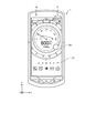
- FIG. 3 is a front view of the smartphone according to the embodiment.
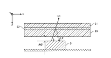
- FIG. 4 is a diagram schematically showing a cross section taken along line II shown in FIG.
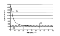
- FIG. 5 is a diagram illustrating a relationship between the output of the proximity sensor and the detection distance according to the embodiment.
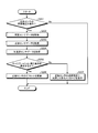
- FIG. 6 is a flowchart illustrating an example of processing by the smartphone according to the embodiment.
- FIG. 7 is a diagram illustrating an example of a user interface according to the embodiment.
- FIG. 8 is a diagram illustrating an example of calibration execution conditions according to another embodiment.
- FIG. 9 is a flowchart illustrating an example of processing by a smartphone according to another embodiment.
- FIG. 10 is a flowchart illustrating an example of processing by a smartphone according to another embodiment.
- FIG. 11 is a flowchart illustrating an example of processing by a smartphone according to another embodiment.
- FIG. 1 is a block diagram illustrating an example of a functional configuration of a smartphone according to the embodiment.
- symbol may be attached
- overlapping description may be omitted.
- the smartphone 1 may be referred to as “own device”.
- the smartphone 1 includes a touch screen display 2, a button 3, an illuminance sensor 4, a proximity sensor 5, a communication unit 6, a receiver 7, a microphone 8, a storage 9, and a controller 10.
- the touch screen display 2 has a display 2A and a touch screen 2B.
- the display 2A and the touch screen 2B may be positioned, for example, may be positioned side by side, or may be positioned apart from each other.
- the display 2A and the touch screen 2B are positioned so as to overlap each other, for example, one or more sides of the display 2A may not be along any of the sides of the touch screen 2B.
- the display 2A is a liquid crystal display (LCD: Liquid Crystal Display), an organic EL display (OELD: Organic Electro-Luminescence Display), or an inorganic EL display (IELD: Inorganic Electro-Luminescence Display device).
- the display 2A displays objects such as characters, images, symbols, and graphics on the screen.
- the screen including the object displayed on the display 2A includes a screen called a lock screen, a screen called a home screen, and an application screen displayed during execution of the application.
- the home screen may be called a desktop, a standby screen, an idle screen, a standard screen, an application list screen, or a launcher screen.
- the controller 10 receives at least one of the contact or proximity detected by the touch screen 2B, the detection position, the change in the detection position, the time that the contact or proximity has continued, the interval at which contact or proximity was detected, and the number of times the contact was detected.
- the type of gesture is determined based on the one.
- the smartphone 1 having the controller 10 can execute operations that the controller 10 can perform. In other words, the operation performed by the controller 10 may be performed by the smartphone 1.
- the gesture is an operation performed on the touch screen 2B using a finger.
- the operation performed on the touch screen 2B may be performed by the touch screen display 2 having the touch screen 2B.
- the gestures that the controller 10 determines via the touch screen 2B include, for example, touch, long touch, release, swipe, tap, double tap, long tap, drag, flick, pinch in, and pinch out. It is not limited to.
- the detection method of the touch screen 2B may be any method such as a capacitance method, a resistive film method, a surface acoustic wave method, an infrared method, and a load detection method.
- buttons 3 accepts operation input from the user.
- the number of buttons 3 may be singular or plural.
- the proximity sensor 5 detects the presence of a nearby object without contact.
- the proximity sensor 5 includes a light emitting element that emits infrared light and a light receiving element that receives reflected infrared light emitted from the light emitting element.
- the illuminance sensor 4 and the proximity sensor 5 may be configured as one sensor.
- the short-range wireless communication standards include, for example, WiMAX (registered trademark) (Worldwide interoperability for Microwave Access), IEEE 802.11, Bluetooth (registered trademark), IrDA (Infrared Data Association), NFC (National Association) ), WPAN (Wireless Personal Area Network), and the like.
- the communication unit 6 may support one or more of the communication standards described above.
- the receiver 7 outputs the sound signal sent from the controller 10 as sound.
- the microphone 8 converts an input user's voice or the like into a sound signal and transmits the sound signal to the controller 10.
- the programs stored in the storage 9 include an application executed in the foreground or the background and a support program (not shown) that supports the operation of the application. For example, when the application is executed in the foreground, a screen related to the application is displayed on the display 2A.
- the support program includes, for example, an OS (Operating System).
- the program may be installed in the storage 9 via wireless communication by the communication unit 6 or a non-transitory storage medium.
- the storage 9 can store a control program 9A, a calibration program 9B, illuminance sensor data 9C, proximity sensor data 9D, acceleration sensor data 9E, calibration execution conditions 9F, setting data 9Z, and the like.
- the control program 9A can provide functions for realizing processes related to various operations of the smartphone 1.
- the function provided by the control program 9A includes a function of adjusting the luminance of the display 2A based on the detection result of the illuminance sensor 4.
- the function provided by the control program 9 ⁇ / b> A includes a function for invalidating the operation on the touch screen 2 ⁇ / b> B based on the detection result of the proximity sensor 5.
- the function provided by the control program 9A includes a function for realizing a call by controlling the communication unit 6, the receiver 7, the microphone 8, and the like.
- the functions provided by the control program 9 ⁇ / b> A include functions for controlling the photographing processing of the camera 12 and the camera 13.
- the function provided by the control program 9A includes a function of controlling communication with an external device connected via the connector 14.
- the function provided by the control program 9A includes a function of performing various controls such as changing information displayed on the display 2A in accordance with a gesture determined based on the detection result of the touch screen 2B.
- Functions provided by the control program 9 ⁇ / b> A include functions for detecting movement, stop, and the like of the user carrying the smartphone 1 based on the detection result of the acceleration sensor 15.
- the function provided by the control program 9A includes a function of executing processing based on the current position based on a signal acquired from the GPS receiver.
- the calibration program 9B can provide a function of calculating an average value of a plurality of data samples included in the proximity sensor data 9D and determining whether the calculated average value is equal to or less than a threshold value.
- the offset update process by the calibration program 9B is started by a user operation, for example.
- the calibration program 9B can provide a user interface related to calibration.
- the illuminance sensor data 9C is all data of detection values detected by the illuminance sensor 4.
- the proximity sensor data 9D is all data of detection values detected by the proximity sensor 5.
- the acceleration sensor data 9E is all data of detection values detected by the acceleration sensor 15.
- the acceleration sensor data 9E includes the direction and magnitude of acceleration acting on the smartphone 1.
- the acceleration sensor data 9E may include all measurement results acquired by the acceleration sensor 15.
- the acceleration sensor data 9E may include an acceleration pattern composed of time-series changes in acceleration direction and magnitude.
- the acceleration sensor 15 is a three-axis type that detects acceleration in the x-axis direction, the y-axis direction, and the z-axis direction
- the acceleration sensor data 9E indicates the direction and magnitude of the acceleration in each axis, and the three-axis type.
- a combined vector obtained by combining accelerations may be included.
- the calibration execution condition 9F includes a condition for updating the offset of the proximity sensor 5.
- FIG. 2 is a diagram illustrating an example of calibration execution conditions according to the embodiment. In the example illustrated in FIG. 2, it is defined that calibration is performed when the detection value d1 of the illuminance sensor 4 is equal to or less than the threshold th1 and the detection value d2 of the proximity sensor 5 is equal to or less than the threshold th2. On the other hand, in the example shown in FIG. 2, it is defined that calibration is not executed when the detection value d1 of the illuminance sensor 4 is larger than the threshold value th1 and the detection value d2 of the proximity sensor 5 is larger than the threshold value th2.
- the detection value d1 of the illuminance sensor 4 is larger than the threshold th1 as one of the necessary conditions for not performing the calibration, for example, an infrared type such as an outdoor place in a sunny day It is possible to avoid the calibration being performed at a place that is not suitable for the calibration of the proximity sensor 5.
- an infrared proximity sensor such as a situation where there is an obstacle above the proximity sensor 5 Calibration in a situation that is not suitable for the calibration of 5 can be avoided.
- the detection value d1 of the illuminance sensor 4 includes, for example, a ratio of data corresponding to an infrared component extracted from a plurality of data samples included in the illuminance sensor data 9C and data corresponding to a visible light component. That is, it is possible to specify a place that is too bright, such as outdoors on a sunny day, based on the ratio of the infrared component contained in the visible light.
- the detection value d2 of the proximity sensor 5 includes an average value of a plurality of data samples included in the proximity sensor data 9D.
- the calibration execution condition 9F is an example of an update condition.
- the setting data 9Z includes information on various settings related to the operation of the smartphone 1.
- the smartphone 1 may access a file and data stored in the cloud storage in cooperation with the cloud storage via the communication unit 6.
- the cloud storage may store a part or all of the programs and data stored in the storage 9.
- the controller 10 includes an arithmetic processing unit.
- the arithmetic processing unit includes, for example, a CPU (Central Processing Unit), an SoC (System-on-a-Chip), an MCU (Micro Control Unit), an FPGA (Field-Programmable Gate Array), and a coprocessor. It is not limited.
- the controller 10 controls various operations of the smartphone 1 to realize various functions.
- the controller 10 executes instructions included in the program stored in the storage 9 while referring to the data stored in the storage 9 as necessary. And the controller 10 controls a function part according to data and a command, and implement
- the functional unit includes, for example, the display 2A, the communication unit 6, the microphone 8, the speaker 11, and the GPS receiver 19, but is not limited thereto.
- the controller 10 may change the control according to the detection result of the detection unit.
- the detection unit includes, for example, the touch screen 2B, the button 3, the illuminance sensor 4, the proximity sensor 5, the microphone 8, the camera 12, the camera 13, the acceleration sensor 15, the azimuth sensor 16, the angular velocity sensor 17, and the atmospheric pressure sensor 18. It is not limited to these.
- the controller 10 can implement various controls related to the operation of the smartphone 1 by executing the control program 9A.
- the controller 10 can realize the process of setting the offset of the proximity sensor 5 on condition that the calibration execution condition 9F is satisfied by executing the calibration program 9B. For example, the controller 10 extracts data corresponding to the infrared component and data corresponding to the visible light component from a plurality of data samples included in the illuminance sensor data 9C, and corresponds to the data corresponding to the infrared component and the visible light component. By calculating the ratio with the data and determining whether the calculated ratio is equal to or less than the threshold, it is possible to execute a process for determining whether the calibration execution condition 9F is satisfied. For example, the controller 10 can execute a process of calculating an average value of a plurality of data samples included in the proximity sensor data 9D and determining whether the calculated average value is equal to or less than a threshold value.
- Speaker 11 outputs a sound signal sent from controller 10 as sound.
- the speaker 11 is used for outputting a ring tone and music, for example.
- One of the receiver 7 and the speaker 11 may also function as the other.
- the camera 12 and the camera 13 convert the captured image into an electrical signal.
- the camera 12 is an in camera that captures an object facing the display 2A.
- the camera 13 is an out camera that captures an object facing the opposite surface of the display 2A.
- the camera 12 and the camera 13 may be mounted on the smartphone 1 in a functionally and physically integrated state as a camera unit that can be used by switching between the in-camera and the out-camera.
- the connector 14 is a terminal to which other devices are connected.
- the connectors 14 are USB (Universal Serial Bus), HDMI (registered trademark) (High-Definition Multimedia Interface), MHL (Mobile High-definition Link), Light Peak (Thunderbolt), Thunderbolt (trade mark), Thorbolt (B) General-purpose terminals such as a LAN connector (Local Area Network connector) and an earphone microphone connector may be used.
- the connector 14 may be a dedicated terminal such as a dock connector. Examples of the device connected to the connector 14 include, but are not limited to, a charger, an external storage, a speaker, a communication device, and an information processing device.
- the acceleration sensor 15 can detect the direction and magnitude of acceleration acting on the smartphone 1.
- a triaxial acceleration sensor 15 that detects acceleration in the X axis direction, the Y axis direction, and the Z axis direction can be employed.
- the acceleration sensor 15 includes a piezoresistive type, a capacitance type, a piezoelectric element type (piezoelectric type), a MEMS (Micro Electro Mechanical Systems) type using a thermal detection type, a servo type that returns the movable coil to an original state by a feedback current, Alternatively, a strain gauge type can be used.
- the acceleration sensor 15 sends the detection result to the controller 10.
- the controller 10 can execute various controls based on the detection result of the acceleration sensor 15. For example, when gravity acting on the smartphone 1 is output from the acceleration sensor 15 as acceleration, the controller 10 can execute control reflecting the direction of gravity acting on the smartphone 1.
- the direction sensor 16 can detect the direction of geomagnetism.
- the direction sensor 16 sends the detection result to the controller 10.
- the controller 10 can execute various controls based on the detection result of the direction sensor 16. For example, the controller 10 can specify the direction (orientation) of the smartphone 1 from the direction of geomagnetism and execute control that reflects the orientation of the identified smartphone 1.
- the angular velocity sensor 17 can detect the angular velocity of the smartphone 1.
- the angular velocity sensor 17 sends the detection result to the controller 10.
- the controller 10 can execute various controls based on the detection result of the angular velocity sensor 17. For example, the controller 10 can realize control reflecting the rotation of the smartphone 1 based on the presence or absence of the angular velocity output from the angular velocity sensor 17.
- the controller 10 is not limited to the case where the detection results of the acceleration sensor 15, the azimuth sensor 16, and the angular velocity sensor 17 are individually used, and the detection results can be used in combination.
- the atmospheric pressure sensor 18 can detect the atmospheric pressure acting on the smartphone 1.
- the detection result of the atmospheric pressure sensor 18 may include an amount of change in atmospheric pressure per unit time.
- the atmospheric pressure change amount may be an absolute value or a value obtained by accumulating a scalar amount.
- An arbitrary time may be set as the unit time.
- the atmospheric pressure sensor 18 sends the detection result to the controller 10.
- the GPS receiver 19 can receive a radio signal of a predetermined frequency band from a GPS satellite.
- the GPS receiver demodulates the received radio signal and sends the processed signal to the controller 10.
- the smartphone 1 may include a vibrator.
- the vibrator vibrates a part or the whole of the smartphone 1.
- the vibrator includes, for example, a piezoelectric element or an eccentric motor in order to generate vibration.
- the smartphone 1 may include a temperature sensor, a humidity sensor, a pressure sensor, and the like in addition to the sensors described above.
- the smartphone 1 is equipped with a function unit that is naturally used to maintain the function of the smartphone 1, such as a battery, and a detection unit that is naturally used to control the smartphone 1.
- FIG. 3 is a front view of the smartphone according to the embodiment.
- the front surface of the smartphone is a surface that faces or contacts the user who uses the smartphone 1, and may be referred to as “front surface” and “display surface” in the following description.
- the smartphone 1 is provided with a protective sheet 21 that covers the entire display surface on the display surface side where the display 2 ⁇ / b> A, the proximity sensor 5, the camera 12, and the like are provided.
- the protective sheet 21 is placed so as to be superimposed directly on the infrared irradiation port of the proximity sensor 5, that is, to cover the entire infrared irradiation port.
- the protective sheet 21 has a predetermined adhesive layer, and is configured to be reattachable by the user.
- the protective sheet 21 prevents the display 2A from being damaged from an impact such as dropping.
- FIG. 4 is a diagram schematically showing a cross section taken along the line II shown in FIG. FIG. 3 shows a cross section when the vicinity of the installation position of the proximity sensor is cut by a plane parallel to the xz plane.
- a protective sheet 21, an adhesive layer 22, and a tempered glass 23 are installed on the proximity sensor 5.
- the protective sheet 21 is attached to the tempered glass 23 by the adhesive layer 22.
- An air gap AG ⁇ b> 1 exists between the proximity sensor 5 and the tempered glass 23.
- the infrared ray L1 emitted from the proximity sensor 5 is reflected not a little on the surface of the protective sheet 21, the adhesive layer 22, and the tempered glass 23 before reaching the proximity detection object, and becomes reflected light L2 to the proximity sensor 5. Is received.
- the air gap AG1, the protective sheet 21, the adhesive layer 22, and the tempered glass 23 affect the transmittance of the infrared ray L1 emitted from the proximity sensor 5.
- the protective sheet 21 covers the entire surface of the infrared irradiation port of the proximity sensor 5, so that the reflected light L ⁇ b> 2 from the protective sheet 21, the adhesive layer 22, and the tempered glass 23 is detected by the proximity sensor 5.
- the offset of the proximity sensor 5 needs to be set so that the distance to the detection target reacts at a desired distance in consideration of the detection value (hereinafter referred to as “crosstalk value” as appropriate). .
- FIG. 5 is a diagram illustrating a relationship between the output of the proximity sensor and the detection distance according to the embodiment.
- 5A shown in FIG. 5 indicates the output of the proximity sensor 5.
- 5B shown in FIG. 5 indicates an output corresponding to the crosstalk value detected by the proximity sensor 5 shown in FIGS. 3 and 4, for example.
- 5C shown in FIG. 5 indicates the allowable change width of the crosstalk value of the proximity sensor 5 when the detection distance is set to 30 millimeters, for example. For example, if the crosstalk value increases for some reason and exceeds the allowable change width (5C), the proximity sensor does not respond at a desired detection distance (for example, 30 millimeters).
- the protective sheet 21 is configured so that it can be freely replaced by a user. Therefore, when the protective sheet 21 is replaced, the material of the replaced protective sheet 21 and the material of the adhesive layer 22 are provided. There is a possibility that the crosstalk value may change depending on the state of application of the protective sheet 21 and the tempered glass 23. For this reason, after the protection sheet 21 is replaced, it is necessary to update the offset again. Therefore, the smartphone 1 according to the embodiment proposes a method of executing the calibration of the proximity sensor 5 when the protection sheet 21 is replaced.
- FIG. 6 is a flowchart illustrating an example of processing by the smartphone according to the embodiment.
- FIG. 7 is a diagram illustrating an example of a user interface according to the embodiment.
- the process shown in FIG. 6 is realized by the controller 10 executing the calibration program 9B.
- the process shown in FIG. 10 is also executed in a mode in which power supply is partially controlled, so-called power saving mode, if the smartphone 1 is operable.
- the controller 10 determines whether there is an instruction to start sensitivity correction of the proximity sensor 5 (step S ⁇ b> 101). Specifically, as illustrated in FIG. 7, when the smartphone 1 receives an operation for “proximity sensor sensitivity correction” on various setting screens SC1 displayed on the display 2A (see “U1” in FIG. 7), the proximity sensor The sensitivity correction screen SC2 is displayed on the display 2A (see “U2” in FIG. 7). Then, when the smartphone 1 receives an operation for “start” on the proximity sensor sensitivity correction screen SC2 (see “U2” in FIG. 7), the smartphone 1 determines that there is an instruction to start sensitivity correction of the proximity sensor 5.
- the controller 10 acquires the illuminance sensor data 9C (step S102) when there is an instruction to start sensitivity correction of the proximity sensor 5 as a result of the determination (step S101, Yes). Subsequently, the controller 10 acquires the proximity sensor data 9D (step S103).
- Controller 10 determines whether or not illuminance sensor data 9C and proximity sensor data 9D satisfy calibration execution condition 9F (step S104).
- the controller 10 updates the offset of the proximity sensor 5 (step S105) when the illuminance sensor data 9C and the proximity sensor data 9D satisfy the calibration execution condition 9F as a result of the determination (step S104, Yes).
- the controller 10 displays a message indicating that the sensitivity correction of the proximity sensor 5 has been successful (step S106), and ends the process shown in FIG.
- the controller 10 displays a message indicating that the sensitivity correction of the proximity sensor 5 has been successful on the processing result screen SC3 displayed on the display 2A (see “U3” in FIG. 7).
- step S104 if the illuminance sensor data 9C and the proximity sensor data 9D do not satisfy the calibration execution condition 9F as a result of the determination (No in step S104), the controller 10 indicates that the sensitivity correction of the proximity sensor 5 has failed. Is displayed (step S107), and the process shown in FIG. For example, as shown in FIG. 7, the controller 10 displays a message indicating that the sensitivity correction of the proximity sensor 5 has failed on the processing result screen SC4 displayed on the display 2A (see “U4” in FIG. 7).
- step S101 if the result of determination is that there is no instruction for starting sensitivity correction of the proximity sensor 5 (No in step S101), the controller 10 ends the processing shown in FIG.
- the smartphone 1 can detect the calibration execution operation by the user who has pasted the protective sheet 21, execute the calibration of the proximity sensor 5, and update the offset of the proximity sensor 5. For this reason, the smart phone 1 can prevent the malfunction of the operation
- the smartphone 1 has described the example of notifying the sensitivity correction processing result by displaying a message on the processing result screen SC3 and the processing result screen SC4 illustrated in FIG. 7, but the present invention is not limited thereto.
- notification may be made by methods such as pop-up display, banner display, icon display on the status bar, and voice output of a message.
- the functional configuration of the smartphone 1 according to another embodiment is basically the same as that of the above embodiment, but differs in the points described below.
- the calibration program 9B determines whether or not the detection values of the illuminance sensor 4 and the proximity sensor 5 and the detection value of the acceleration sensor 15 satisfy the calibration execution condition 9F in a predetermined cycle after the offset is updated. As a result of the determination, when the calibration execution condition 9F is satisfied, a function of updating the offset can be provided.
- the predetermined period is set to an arbitrary time for the purpose of periodically reviewing the proximity sensor offset, for example. Arbitrary time may be set as the predetermined cycle.
- FIG. 8 is a diagram illustrating an example of calibration execution conditions according to another embodiment.
- the detection value d1 of the illuminance sensor 4 is not more than the threshold th1, the detection value d2 of the proximity sensor 5 is not more than the threshold th2, and the detection value d3 of the acceleration sensor 15 is not more than the threshold th3.
- the detection value d1 of the illuminance sensor 4 is larger than the threshold th1, the detection value d2 of the proximity sensor 5 is larger than the threshold th2, and the detection value d3 of the acceleration sensor 15 is larger than the threshold th3. If it is larger, it is specified that calibration is not executed.
- the case where the detected value d3 of the acceleration sensor 15 is larger than the threshold th3 is incorporated as one of the necessary conditions for not performing the calibration, so that the smartphone 1 can be held and moved. It is possible to prevent the calibration from being executed in a situation where the smartphone 1 is unstable and is not suitable for the calibration of the infrared proximity sensor 5, such as the state of The calibration execution condition 9F is an example of an update condition.
- the controller 10 executes the calibration program 9B, so that the detection values of the illuminance sensor 4 and the proximity sensor 5 and the detection value of the acceleration sensor 15 satisfy the calibration execution condition 9F in a predetermined cycle after the offset is updated. If the calibration execution condition 9F is satisfied as a result of the determination, a process for updating the offset is realized.
- FIG. 9 is a flowchart showing an example of processing by a smartphone according to another embodiment.
- the process shown in FIG. 9 is realized by the controller 10 executing the calibration program 9B.
- the process shown in FIG. 9 is also executed in a mode in which power supply is partially controlled, that is, a so-called power saving mode, if the smartphone 1 is operable.
- the controller 10 determines whether or not the execution period of sensitivity correction of the proximity sensor 5 has been reached (step S201).
- Controller 10 obtains illuminance sensor data 9C (step S202) when it is determined that the sensitivity correction execution period has been reached (step S201, Yes). Subsequently, the controller 10 acquires the proximity sensor data 9D (step S203). Subsequently, the controller 10 acquires acceleration sensor data 9E (step S204).
- Controller 10 determines whether or not illuminance sensor data 9C, proximity sensor data 9D, and acceleration sensor data 9E satisfy calibration execution condition 9F (step S205).
- the controller 10 updates the offset of the proximity sensor 5 (step S205). S206).
- step S205 if the illuminance sensor data 9C, the proximity sensor data 9D, and the acceleration sensor data 9E do not satisfy the calibration execution condition 9F (No in step S205), the controller 10 fails to correct the sensitivity of the proximity sensor 5 as a result of the determination. A message to the effect is displayed (step S207), and the process shown in FIG. 9 is terminated.
- step S201 if the controller 10 does not execute sensitivity correction as a result of the determination (step S201, No), the process illustrated in FIG. 9 ends.
- the smartphone 1 may execute a step of displaying a message indicating that the sensitivity correction has been successful, as shown in FIGS.
- the smartphone 1 since the smartphone 1 periodically updates the offset of the proximity sensor 5, the sensitivity of the proximity sensor 5 can be maintained as much as possible.
- the update of the offset of the proximity sensor 5 may be executed at various occasions other than a predetermined cycle.
- FIG.10 and FIG.11 is a flowchart which shows an example of the process by the smart phone which concerns on other embodiment.
- FIG. 10 shows an example of processing for updating the offset of the proximity sensor based on the change in the crosstalk value of the proximity sensor 5.
- the controller 10 determines whether or not the crosstalk value of the proximity sensor 5 is greater than or equal to a threshold value (step S301). For example, the controller 10 estimates the crosstalk value from the output of the proximity sensor 5, and the difference (change amount) between the estimated crosstalk value and the offset being set (initial setting value at the time of product shipment) is a threshold value (for example, , It is determined whether the change allowable width is 5C (see FIG. 5) or more.
- the crosstalk value when used at the user's hand can be estimated from the average of the outputs when the proximity sensor is not responding (when a predetermined distance is not detected), for example. The average may be calculated based on the output of the proximity sensor detected within an arbitrary time.
- Controller 10 obtains illuminance sensor data 9C (step S302) when the crosstalk value is equal to or greater than the threshold value as a result of the determination (step S301, Yes). Subsequently, the controller 10 acquires the proximity sensor data 9D (step S303). Subsequently, the controller 10 acquires acceleration sensor data 9E (step S304).
- Controller 10 determines whether illuminance sensor data 9C, proximity sensor data 9D, and acceleration sensor data 9E satisfy calibration execution condition 9F (step S305).
- Step S305 If the illuminance sensor data 9C, the proximity sensor data 9D, and the acceleration sensor data 9E satisfy the calibration execution condition 9F as a result of the determination (Step S305, Yes), the controller 10 updates the offset of the proximity sensor 5 (Step S305). S306).
- step S305 the controller 10 fails to correct the sensitivity of the proximity sensor 5 as a result of the determination.
- a message to the effect is displayed (step S307), and the process shown in FIG.
- step S301 if the result of determination is that the crosstalk value is not greater than or equal to the threshold value (No in step S301), the controller 10 ends the processing shown in FIG.
- the smartphone 1 may execute a step of displaying a message indicating that the sensitivity correction has been successful, as shown in FIGS. 6 and 7.
- the smartphone 1 when the smartphone 1 is used, the surface of the protective sheet 21 is damaged, the light transmittance of the protective sheet 21 is changed, or the adhesive layer 22 is deteriorated due to heat or light. It is conceivable that the light transmittance of the light changes.
- the smartphone 1 monitors the change in the crosstalk value of the proximity sensor 5, for example, damage to the protective sheet 21 and deterioration of the adhesive layer 22 are manifested in the form of a change in the crosstalk value. Can deal with the case.
- the smart phone 1 can update the offset of the proximity sensor 5 following the change of the crosstalk value, it is easy to manage the sensitivity of the proximity sensor 5 in an effective state.
- FIG. 11 shows an example of processing for updating the offset of the proximity sensor at the timing when fingerprint authentication is executed.
- the controller 10 determines whether fingerprint authentication has been executed (step S401).
- Controller 10 obtains illuminance sensor data 9C (step S402) when fingerprint authentication is executed as a result of the determination (step S401, Yes). Subsequently, the controller 10 acquires the proximity sensor data 9D (step S403). Subsequently, the controller 10 acquires acceleration sensor data 9E (step S404).
- Controller 10 determines whether illuminance sensor data 9C, proximity sensor data 9D, and acceleration sensor data 9E satisfy calibration execution condition 9F (step S405).
- Step S405 If the illuminance sensor data 9C, the proximity sensor data 9D, and the acceleration sensor data 9E satisfy the calibration execution condition 9F as a result of the determination (Step S405, Yes), the controller 10 updates the offset of the proximity sensor 5 (Step S405). S406).
- step S405 the controller 10 fails to correct the sensitivity of the proximity sensor 5 as a result of the determination. A message to the effect is displayed (step S407), and the process shown in FIG. 11 is terminated.
- step S401 if the result of determination is that fingerprint authentication has not been executed (step S401, No), the controller 10 ends the processing shown in FIG.
- the smartphone 1 may execute a step of displaying a message indicating that the sensitivity correction has been successful, as shown in FIGS. 6 and 7.
- the smartphone 1 may exclude the proximity sensor data 9D from the determination target of the calibration execution condition 9F. That is, when fingerprint authentication is executed in the smartphone 1, it is assumed that there is no obstacle above the proximity sensor 5, so the proximity sensor that is a determination index of whether there is an obstacle above the proximity sensor 5. The purpose is to exclude the data 9D from the beginning.
Landscapes
- Physics & Mathematics (AREA)
- General Physics & Mathematics (AREA)
- Spectroscopy & Molecular Physics (AREA)
- Engineering & Computer Science (AREA)
- Signal Processing (AREA)
- Telephone Function (AREA)
- Photometry And Measurement Of Optical Pulse Characteristics (AREA)
Abstract
近接センサの感度補正を改善することを目的として、態様の1つに係る電子機器は、赤外線型の近接センサと、前記近接センサの近傍に設けられる照度センサと、前記近接センサの検出値の補正に用いる基準値の更新条件を記憶するストレージと、制御部とを備える。当該制御部は、前記照度センサの検出値及び前記近接センサの検出値が前記更新条件を満足するかを判定する。当該制御部は、判定の結果、前記更新条件を満足する場合、前記基準値を更新する。
Description
本出願は、日本国出願2017-115673号(2017年6月13日出願)の優先権を主張するものであり、当該出願の開示全体を、ここに参照のために取り込む。
本出願は、電子機器、感度補正方法及び感度補正プログラムに関する。
従来、近接センサの感度を補正することを目的として、所定のタイミングで近接センサの基準値を更新する装置がある。
1つの態様に係る電子機器は、赤外線型の近接センサと、前記近接センサの近傍に設けられる照度センサと、前記近接センサの検出値の補正に用いる基準値の更新条件を記憶するストレージと、制御部とを備える。当該制御部は、前記照度センサの検出値及び前記近接センサの検出値が前記更新条件を満足するかを判定し、判定の結果、前記更新条件を満足する場合、前記基準値を更新する。
1つの態様に係る感度補正方法は、近接センサと、当該近接センサの近傍に設けられる照度センサと、前記近接センサの検出値の補正に用いる基準値の更新条件を記憶するストレージとを備える電子機器に実行させる感度補正方法である。当該感度補正方法は、前記照度センサの検出値及び前記近接センサの検出値が前記更新条件を満足するかを判定し、判定の結果、前記更新条件を満足する場合、前記基準値を更新するステップを含む。
1つの態様に係る感度補正プログラムは、近接センサと、当該近接センサの近傍に設けられる照度センサと、前記近接センサの検出値の補正に用いる基準値の更新条件を記憶するストレージとを備える電子機器に、前記照度センサの検出値及び前記近接センサの検出値が前記更新条件を満足するかを判定し、判定の結果、前記更新条件を満足する場合、前記基準値を更新するステップを実行させる。
本出願に係る実施形態を、図面を参照しつつ詳細に説明する。以下の説明において、同様の構成要素について同一の符号を付すことがある。さらに、重複する説明は省略することがある。以下では、本出願に係る電子機器の一例として、スマートフォンを取り上げて説明する。
図1は、実施形態に係るスマートフォンの機能構成の一例を示すブロック図である。以下の説明において、同様の構成要素について同一の符号を付すことがある。以下の説明において、重複する説明は省略することがある。以下の説明において、スマートフォン1を「自機」と表記する場合がある。
図1に示すように、スマートフォン1は、タッチスクリーンディスプレイ2と、ボタン3と、照度センサ4と、近接センサ5と、通信ユニット6と、レシーバ7と、マイク8と、ストレージ9と、コントローラ10と、スピーカ11と、カメラ12と、カメラ13と、コネクタ14と、加速度センサ15と、方位センサ16と、角速度センサ17と、気圧センサ18と、GPS受信機19とを含む。
タッチスクリーンディスプレイ2は、ディスプレイ2Aと、タッチスクリーン2Bとを有する。ディスプレイ2A及びタッチスクリーン2Bは、例えば、重なって位置してよいし、並んで位置してよいし、離れて位置してよい。ディスプレイ2Aとタッチスクリーン2Bとが重なって位置する場合、例えば、ディスプレイ2Aの1ないし複数の辺は、タッチスクリーン2Bのいずれの辺とも沿っていなくてもよい。
ディスプレイ2Aは、液晶ディスプレイ(LCD:Liquid Crystal Display)、有機ELディスプレイ(OELD:Organic Electro-Luminescence Display)、又は無機ELディスプレイ(IELD:Inorganic Electro-Luminescence Display)等の表示デバイスを含む。ディスプレイ2Aは、文字、画像、記号、及び図形等のオブジェクトを画面内に表示する。ディスプレイ2Aが表示するオブジェクトを含む画面は、ロック画面と呼ばれる画面、ホーム画面と呼ばれる画面、アプリケーションの実行中に表示されるアプリケーション画面を含む。ホーム画面は、デスクトップ、待受画面、アイドル画面、標準画面、アプリ一覧画面又はランチャー画面と呼ばれることもある。
タッチスクリーン2Bは、タッチスクリーン2Bに対する指、ペン、又はスタイラスペン等の接触又は近接を検出する。タッチスクリーン2Bは、複数の指、ペン、又はスタイラスペン等がタッチスクリーン2Bに接触又は近接したときのタッチスクリーン2B上の位置を検出することができる。以下の説明において、タッチスクリーン2Bが検出する複数の指、ペン、及びスタイラスペン等がタッチスクリーン2Bに接触又は近接した位置を「検出位置」と表記する。タッチスクリーン2Bは、タッチスクリーン2Bに対する指の接触又は近接を、検出位置とともにコントローラ10に通知する。タッチスクリーン2Bは、検出位置の通知をもって接触又は近接の検出をコントローラ10に通知してよい。タッチスクリーン2Bが行える動作を、タッチスクリーン2Bを有するタッチスクリーンディスプレイ2は実行できる。言い換えると、タッチスクリーン2Bが行う動作は、タッチスクリーンディスプレイ2が行ってもよい。
コントローラ10は、タッチスクリーン2Bにより検出された接触又は近接、検出位置、検出位置の変化、接触又は近接が継続した時間、接触又は近接が検出された間隔、及び接触が検出された回数の少なくとも1つに基づいて、ジェスチャの種別を判別する。コントローラ10が行える動作を、コントローラ10を有するスマートフォン1は実行できる。言い換えると、コントローラ10が行う動作は、スマートフォン1が行ってもよい。ジェスチャは、指を用いて、タッチスクリーン2Bに対して行われる操作である。タッチスクリーン2Bに対して行われる操作は、タッチスクリーン2Bを有するタッチスクリーンディスプレイ2により行われてもよい。コントローラ10が、タッチスクリーン2Bを介して判別するジェスチャには、例えば、タッチ、ロングタッチ、リリース、スワイプ、タップ、ダブルタップ、ロングタップ、ドラッグ、フリック、ピンチイン、及びピンチアウトが含まれるが、これらに限定されない。
タッチスクリーン2Bの検出方式は、静電容量方式、抵抗膜方式、表面弾性波方式、赤外線方式、及び荷重検出方式等の任意の方式でよい。
ボタン3は、ユーザからの操作入力を受け付ける。ボタン3の数は、単数であっても、複数であってもよい。
照度センサ4は、照度を検出する。照度は、照度センサ4の測定面の単位面積に入射する光束の値である。照度センサ4は、例えば、ディスプレイ2Aの輝度の調整に用いられる。
近接センサ5は、近隣の物体の存在を非接触で検出する。近接センサ5は、赤外線を照射する発光素子と、発光素子から照射された赤外線の反射光を受光する受光素子を有する。照度センサ4及び近接センサ5は、1つのセンサとして構成されていてもよい。
通信ユニット6は、無線により通信する。通信ユニット6によってサポートされる無線通信規格には、例えば、2G、3G、4G、5G等のセルラーフォンの通信規格と、近距離無線の通信規格とが含まれる。セルラーフォンの通信規格としては、例えば、LTE(Long Term Evolution)、W-CDMA(登録商標)(Wideband Code Division Multiple Access)、CDMA2000、PDC(Personal Digital Cellular)、GSM(登録商標)(Global System for Mobile communications)、PHS(Personal Handy-phone System)等がある。近距離無線の通信規格としては、例えば、WiMAX(登録商標)(Worldwide interoperability for Microwave Access)、IEEE802.11、Bluetooth(登録商標)、IrDA(Infrared Data Association)、NFC(登録商標)(Near Field Communication)、WPAN(Wireless Personal Area Network)等が含まれる。通信ユニット6は、上述した通信規格の1つ又は複数をサポートしていてもよい。
レシーバ7は、コントローラ10から送出される音信号を音として出力する。マイク8は、入力されるユーザの声等を音信号へ変換してコントローラ10へ送信する。
ストレージ9は、プログラム及びデータを記憶する。ストレージ9は、コントローラ10の処理結果を一時的に記憶する作業領域として利用されてもよい。ストレージ9は、半導体記憶媒体、及び磁気記憶媒体等の任意の非一過的(non-transitory)な記憶媒体を含んでよい。ストレージ9は、複数の種類の記憶媒体を含んでよい。ストレージ9は、メモリカード、光ディスク、又は光磁気ディスク等の記憶媒体と、記憶媒体の読み取り装置との組み合わせを含んでよい。ストレージ9は、RAM(Random Access Memory)等の一時的な記憶領域として利用される記憶デバイスを含んでよい。
ストレージ9に記憶されるプログラムには、フォアグランド又はバックグランドで実行されるアプリケーションと、アプリケーションの動作を支援する支援プログラム(図示略)とが含まれる。アプリケーションは、例えば、フォアグランドで実行される場合、当該アプリケーションに係る画面を、ディスプレイ2Aに表示する。支援プログラムには、例えば、OS(Operating System)が含まれる。プログラムは、通信ユニット6による無線通信又は非一過的な記憶媒体を介してストレージ9にインストールされてもよい。
ストレージ9は、制御プログラム9A、キャリブレーションプログラム9B、照度センサデータ9C、近接センサデータ9D、加速度センサデータ9E、キャリブレーション実行条件9F、及び設定データ9Zなどを記憶できる。
制御プログラム9Aは、スマートフォン1の各種動作に関する処理を実現するための機能をそれぞれ提供できる。制御プログラム9Aが提供する機能は、照度センサ4の検出結果に基づいて、ディスプレイ2Aの輝度を調整する機能を含む。制御プログラム9Aが提供する機能は、近接センサ5の検出結果に基づいて、タッチスクリーン2Bに対する操作を無効とする機能を含む。制御プログラム9Aが提供する機能は、通信ユニット6、レシーバ7、及びマイク8等を制御することによって、通話を実現させる機能を含む。制御プログラム9Aが提供する機能は、カメラ12、及びカメラ13の撮影処理を制御する機能を含む。制御プログラム9Aが提供する機能は、コネクタ14を介して接続される外部機器との間の通信を制御する機能を含む。制御プログラム9Aが提供する機能は、タッチスクリーン2Bの検出結果に基づいて判別したジェスチャに応じて、ディスプレイ2Aに表示されている情報を変更する等の各種制御を行う機能を含む。制御プログラム9Aが提供する機能は、加速度センサ15の検出結果に基づいて、スマートフォン1を携帯するユーザの移動、停止等を検出する機能を含む。制御プログラム9Aが提供する機能は、GPS受信機より取得する信号に基づいて、現在位置に基づく処理を実行する機能を含む。
キャリブレーションプログラム9Bは、照度センサデータ9C及び近接センサデータ9Dがキャリブレーション実行条件9Fを満足することを条件として、近接センサ5の検出値の補正に用いる基準値(以下、適宜「オフセット」と記載する)を更新する機能を提供できる。キャリブレーションプログラム9Bは、照度センサデータ9Cに含まれる複数のデータサンプルから、赤外線成分に対応するデータ及び可視光成分に対応するデータを抽出し、赤外線成分に対応するデータと可視光成分に対応するデータとの比が閾値以下であるかを判定する機能を提供できる。キャリブレーションプログラム9Bは、近接センサデータ9Dに含まれる複数のデータサンプルの平均値を算出し、算出した平均値が閾値以下であるかを判定する機能を提供できる。キャリブレーションプログラム9Bによるオフセットの更新処理は、例えば、ユーザの操作によって開始される。キャリブレーションプログラム9Bは、キャリブレーションに関連するユーザインタフェースを提供できる。
照度センサデータ9Cは、照度センサ4により検出される検出値の全データである。近接センサデータ9Dは、近接センサ5により検出される検出値の全データである。加速度センサデータ9Eは、加速度センサ15により検出される検出値の全データである。加速度センサデータ9Eは、スマートフォン1に作用する加速度の方向及び大きさを含む。加速度センサデータ9Eは、加速度センサ15により取得される全ての測定結果を含んでよい。例えば、加速度センサデータ9Eは、加速度の方向及び大きさの時系列変化で構成される加速度パターンを含んでよい。例えば、加速度センサデータ9Eは、加速度センサ15がx軸方向、y軸方向、及びz軸方向の加速度を検出する3軸型である場合、各軸における加速度の方向及び大きさ、並びに3軸の加速度を合成した合成ベクトルを含んでよい。
キャリブレーション実行条件9Fは、近接センサ5のオフセットを更新するための条件を含む。図2は、実施形態に係るキャリブレーション実行条件の一例を示す図である。図2に示す例では、照度センサ4の検出値d1が閾値th1以下であり、かつ近接センサ5の検出値d2が閾値th2以下である場合、キャリブレーションを実行することが規定されている。一方、図2に示す例では、照度センサ4の検出値d1が閾値th1より大きく、かつ近接センサ5の検出値d2が閾値th2よりも大きい場合、キャリブレーションを実行しないことが規定されている。
すなわち、照度センサ4の検出値d1が閾値th1より大きい場合を、キャリブレーションを実行しない必要条件の1つとして組み入れることにより、例えば、晴れた日中の屋外などの明る過ぎる場所など、赤外線型の近接センサ5のキャリブレーションに適していない場所でキャリブレーションが実行されることを避けることができる。近接センサ5の検出値d2が閾値th2より大きい場合を、キャリブレーションを実行しない必要条件の1つとして組み入れることにより、例えば、近接センサ5の上部に障害物がある状況など、赤外線型の近接センサ5のキャリブレーションに適していない状況でのキャリブレーションを避けることができる。照度センサ4の検出値d1は、例えば、照度センサデータ9Cに含まれる複数のデータサンプルから抽出した赤外線成分に対応するデータと可視光成分に対応するデータとの比を含む。すなわち、赤外線成分が可視光に含まれる割合に基づいて、晴れた日中の屋外などの明る過ぎる場所を特定できる。近接センサ5の検出値d2は、近接センサデータ9Dに含まれる複数のデータサンプルの平均値を含む。キャリブレーション実行条件9Fは、更新条件の一例である。
設定データ9Zは、スマートフォン1の動作に関する各種設定の情報を含む。
スマートフォン1は、通信ユニット6を介してクラウドストレージと連携し、当該クラウドストレージが記憶するファイル及びデータにアクセスしてもよい。クラウドストレージは、ストレージ9に記憶されるプログラム及びデータの一部又は全部を記憶してもよい。
コントローラ10は、演算処理装置を含む。演算処理装置は、例えば、CPU(Central Processing Unit)、SoC(System-on-a-Chip)、MCU(Micro Control Unit)、FPGA(Field-Programmable Gate Array)、およびコプロセッサを含むが、これらに限定されない。コントローラ10は、スマートフォン1の動作を統括的に制御して各種の機能を実現する。
具体的には、コントローラ10は、ストレージ9に記憶されているデータを必要に応じて参照しつつ、ストレージ9に記憶されているプログラムに含まれる命令を実行する。そして、コントローラ10は、データ及び命令に応じて機能部を制御し、それによって各種機能を実現する。機能部は、例えば、ディスプレイ2A、通信ユニット6、マイク8、スピーカ11及びGPS受信機19を含むが、これらに限定されない。コントローラ10は、検出部の検出結果に応じて、制御を変更することがある。検出部は、例えば、タッチスクリーン2B、ボタン3、照度センサ4、近接センサ5、マイク8、カメラ12、カメラ13、加速度センサ15、方位センサ16、角速度センサ17、及び気圧センサ18を含むが、これらに限定されない。
コントローラ10は、制御プログラム9Aを実行することにより、スマートフォン1の動作に関する各種制御を実現できる。
コントローラ10は、キャリブレーションプログラム9Bを実行することにより、キャリブレーション実行条件9Fを満足することを条件として、近接センサ5のオフセットを設定する処理を実現できる。コントローラ10は、例えば、照度センサデータ9Cに含まれる複数のデータサンプルから、赤外線成分に対応するデータ及び可視光成分に対応するデータを抽出し、赤外線成分に対応するデータと可視光成分に対応するデータとの比を算出して、算出した比が閾値以下であるかを判定することにより、キャリブレーション実行条件9Fを満足するかを判定する処理を実行できる。コントローラ10は、例えば、近接センサデータ9Dに含まれる複数のデータサンプルの平均値を算出し、算出した平均値が閾値以下であるかを判定する処理を実行できる。
スピーカ11は、コントローラ10から送出される音信号を音として出力する。スピーカ11は、例えば、着信音及び音楽を出力するために用いられる。レシーバ7及びスピーカ11の一方が、他方の機能を兼ねてもよい。
カメラ12及びカメラ13は、撮影した画像を電気信号へ変換する。カメラ12は、ディスプレイ2Aに面している物体を撮影するインカメラである。カメラ13は、ディスプレイ2Aの反対側の面に面している物体を撮影するアウトカメラである。カメラ12及びカメラ13は、インカメラ及びアウトカメラを切り換えて利用可能なカメラユニットとして、機能的及び物理的に統合された状態でスマートフォン1に実装されてもよい。
コネクタ14は、他の装置が接続される端子である。コネクタ14は、USB(Universal Serial Bus)、HDMI(登録商標)(High-Definition Multimedia Interface)、MHL(Mobile High-difinition Link)、ライトピーク(Light Peak)、サンダーボルト(登録商標)(Thunderbolt)、LANコネクタ(Local Area Network connector)、イヤホンマイクコネクタのような汎用的な端子であってもよい。コネクタ14は、Dockコネクタのような専用に設計された端子でもよい。コネクタ14に接続される装置は、例えば、充電器、外部ストレージ、スピーカ、通信装置、及び情報処理装置を含むが、これらに限定されない。
加速度センサ15は、スマートフォン1に作用する加速度の方向及び大きさを検出できる。実施形態の1つの例として、X軸方向、Y軸方向、及びZ軸方向の加速度を検出する3軸型の加速度センサ15を採用できる。加速度センサ15は、ピエゾ抵抗型、静電容量型、圧電素子型(圧電式)、熱検知型によるMEMS(Micro Electro Mechanical Systems)式、動作させた可動コイルをフィードバック電流により元に戻すサーボ式、あるいは歪みゲージ式などにより構成することができる。加速度センサ15は、検出結果をコントローラ10に送出する。コントローラ10は、加速度センサ15の検出結果に基づいて各種制御を実行できる。例えば、スマートフォン1に作用している重力が加速度として加速度センサ15から出力されると、コントローラ10は、スマートフォン1に作用する重力方向を反映した制御を実行できる。
方位センサ16は、地磁気の向きを検出できる。方位センサ16は、検出結果をコントローラ10に送出する。コントローラ10は、方位センサ16の検出結果に基づいて各種制御を実行できる。例えば、コントローラ10は、地磁気の向きからスマートフォン1の向き(方位)を特定し、特定したスマートフォン1の方位を反映した制御を実行できる。
角速度センサ17は、スマートフォン1の角速度を検出できる。角速度センサ17は、検出結果をコントローラ10に送出する。コントローラ10は、角速度センサ17の検出結果に基づいて各種制御を実行できる。例えば、コントローラ10は、角速度センサ17から出力される角速度の有無に基づいて、スマートフォン1の回転を反映した制御を実現できる。
コントローラ10は、加速度センサ15、方位センサ16、及び角速度センサ17の各検出結果を個別に利用する場合に限定されず、各検出結果を組み合わせて利用することもできる。
気圧センサ18は、スマートフォン1に作用する気圧を検出できる。気圧センサ18の検出結果は、単位時間あたりの気圧変化量を含んでよい。気圧変化量は、絶対値もしくはスカラー量を累積した値であってよい。単位時間は、任意の時間を設定してよい。気圧センサ18は、検出結果をコントローラ10に送出する。
GPS受信機19は、GPS衛星からの所定の周波数帯の電波信号を受信できる。GPS受信機は、受信した電波信号の復調処理を行って、処理後の信号をコントローラ10に送出する。
スマートフォン1は、バイブレータを備えてもよい。バイブレータは、スマートフォン1の一部又は全体を振動させる。バイブレータは、振動を発生させるために、例えば、圧電素子、又は偏心モータなどを有する。スマートフォン1は、上述のセンサの他、温度センサ、湿度センサ、圧力センサなどを備えてもよい。スマートフォン1は、バッテリなど、スマートフォン1の機能を維持するために当然に用いられる機能部、及びスマートフォン1の制御を実現するために当然に用いられる検出部を実装する。
図3は、実施形態に係るスマートフォンの正面図である。以下の説明において、スマートフォンの正面は、スマートフォン1を利用するユーザと対面する、あるいはユーザに接する面であり、以下の説明おいて「正面」及び「表示面」と記載する場合がある。図3に示すように、スマートフォン1は、ディスプレイ2A、近接センサ5、及びカメラ12などが設けられる表示面側に、表示面の全面を覆う保護シート21が設けられる。すなわち、保護シート21は、近接センサ5の赤外線照射口の真上、すなわち、赤外線照射口全体を覆うように重畳されて設置される。保護シート21は、所定の接着層を有し、ユーザによる貼り換え自在に構成される。保護シート21は、落下等の衝撃からディスプレイ2Aの破損を防止する。
図4は、図3に示すI-I線における断面を模式的に示す図である。図3は、近接センサの設置位置の周辺をxz平面に平行な面で切断したときの断面を示している。図3に示すように、近接センサ5の上部に、保護シート21、接着層22、及び強化ガラス23が設置されている。保護シート21は、接着層22により強化ガラス23に貼り付けられている。近接センサ5と強化ガラス23との間に、エアギャップAG1が存在する。近接センサ5から照射される赤外線L1は、近接検知対象物に到達する前に、保護シート21、接着層22、及び強化ガラス23の表面で少なからず反射し、反射光L2となって近接センサ5により受光される。このように、エアギャップAG1、保護シート21、接着層22、及び強化ガラス23は、近接センサ5から照射される赤外線L1の透過率に影響を与える。保護シート21は、図3に示すように、近接センサ5の赤外線照射口の全面を覆うので、保護シート21、接着層22、及び強化ガラス23からの反射光L2が、近接センサ5によって検出されるときの検出値(以下、適宜「クロストーク値」と記載する)を考慮して、検知対象物との距離が所望の距離で反応するように、近接センサ5のオフセットを設定する必要がある。
図5は、実施形態に係る近接センサの出力と検知距離との関係を示す図である。図5に示す5Aは、近接センサ5の出力を示す。図5に示す5Bは、例えば、図3及び図4に示す近接センサ5により検出されるクロストーク値に相当する出力を示す。図5に示す5Cは、例えば、検知距離を30ミリメートルに設定した場合における近接センサ5のクロストーク値の変化許容幅を示す。例えば、何らかの要因で、クロストーク値が大きくなり、変化許容幅(5C)を超えると、近接センサが所望の検知距離(例えば、30ミリメートル)で反応しなくなってしまう。
保護シート21は、例えば、ユーザによる貼り換えが自在に行えるように構成されるので、保護シート21の貼り換えが行われた場合、貼り換えられた保護シート21の素材並びに接着層22の材料、保護シート21と強化ガラス23との貼付状況などにより、クロストーク値が変化するおそれがある。このため、保護シート21の貼り換え後は、再びオフセットを更新する必要がある。そこで、実施形態に係るスマートフォン1は、保護シート21の貼り換えが行われた場合、近接センサ5のキャリブレーションを実行する方法を提案する。
図6及び図7を用いて、実施形態に係るスマートフォン1による処理の例を説明する。図6は、実施形態に係るスマートフォンによる処理の一例を示すフローチャートである。図7は、実施形態に係るユーザインタフェースの一例を示す図である。図6に示す処理は、コントローラ10がキャリブレーションプログラム9Bを実行することにより実現される。図10に示す処理は、スマートフォン1が動作可能な状態であれば、給電を一部制御するモード、いわゆる省電力モードのときにも実行される。
図6に示すように、コントローラ10は、近接センサ5の感度補正開始指示があったかを判定する(ステップS101)。具体的には、図7に示すように、スマートフォン1は、ディスプレイ2Aに表示する各種設定画面SC1において、「近接センサ感度補正」に対する操作を受け付けると(図7の「U1」参照)、近接センサ感度補正画面SC2をディスプレイ2Aに表示する(図7の「U2」参照)。そして、スマートフォン1は、近接センサ感度補正画面SC2において、「開始」に対する操作を受け付けると(図7の「U2」参照)、近接センサ5の感度補正開始指示があったものと判定する。
コントローラ10は、判定の結果、近接センサ5の感度補正開始指示があった場合(ステップS101,Yes)、照度センサデータ9Cを取得する(ステップS102)。続いて、コントローラ10は、近接センサデータ9Dを取得する(ステップS103)。
コントローラ10は、照度センサデータ9C及び近接センサデータ9Dがキャリブレーション実行条件9Fを満足するか否かを判定する(ステップS104)。
コントローラ10は、判定の結果、照度センサデータ9C及び近接センサデータ9Dがキャリブレーション実行条件9Fを満足する場合(ステップS104,Yes)、近接センサ5のオフセットを更新する(ステップS105)。
続いて、コントローラ10は、近接センサ5の感度補正に成功した旨のメッセージを表示して(ステップS106)、図6に示す処理を終了する。例えば、コントローラ10は、図7に示すように、ディスプレイ2Aに表示する処理結果画面SC3に近接センサ5の感度補正に成功した旨のメッセージを表示する(図7の「U3」参照)。
ステップS104において、コントローラ10は、判定の結果、照度センサデータ9C及び近接センサデータ9Dがキャリブレーション実行条件9Fを満足しない場合(ステップS104,No)、近接センサ5の感度補正に失敗した旨のメッセージを表示して(ステップS107)、図6に示す処理を終了する。例えば、コントローラ10は、図7に示すように、ディスプレイ2Aに表示する処理結果画面SC4に近接センサ5の感度補正に失敗した旨のメッセージを表示する(図7の「U4」参照)。
ステップS101において、コントローラ10は、判定の結果、近接センサ5の感度補正開始指示がない場合(ステップS101,No)、図6に示す処理を終了する。
上記の実施形態では、スマートフォン1が、保護シート21の貼り換えを行ったユーザによるキャリブレーション実行操作を検出して、近接センサ5のキャリブレーションを実行し、近接センサ5のオフセットを更新できる。このため、スマートフォン1は、例えば、保護シート21の貼り換えを原因とする近接センサ5の動作の不具合を防止できる。
上記の実施形態において、スマートフォン1は、図7に示す処理結果画面SC3及び処理結果画面SC4にメッセージを表示することにより、感度補正の処理結果を通知する例を説明したが、これには限定されず、ポップアップ表示、バナー表示、ステータスバーへのアイコン表示、メッセージの音声出力などの方法により通知してもよい。
(他の実施形態)
上記の実施形態では、ユーザによるキャリブレーション実行操作を検出してオフセットの更新を実行する例を説明したが、以下の実施形態では、オフセットの自動更新について説明する。
上記の実施形態では、ユーザによるキャリブレーション実行操作を検出してオフセットの更新を実行する例を説明したが、以下の実施形態では、オフセットの自動更新について説明する。
他の実施形態に係るスマートフォン1の機能的な構成は、基本的には、上記の実施形態と同様であるが、以下に説明する点が異なる。
キャリブレーションプログラム9Bは、オフセットの更新後、所定の周期で、照度センサ4及び近接センサ5の検出値、並びに加速度センサ15の検出値がキャリブレーション実行条件9Fを満足するか否かを判定し、判定の結果、キャリブレーション実行条件9Fを満足する場合、オフセットを更新する機能を提供できる。所定の周期は、例えば、近接センサのオフセットについて定期的な見直しを実施する目的で任意の時間が設定される。所定の周期は、任意の時間が設定されてよい。
図8は、他の実施形態に係るキャリブレーション実行条件の一例を示す図である。図8に示す例では、照度センサ4の検出値d1が閾値th1以下であり、近接センサ5の検出値d2が閾値th2以下であり、さらに、加速度センサ15の検出値d3が閾値th3以下である場合、キャリブレーションを実行することが規定されている。一方、図8に示す例では、照度センサ4の検出値d1が閾値th1より大きく、かつ近接センサ5の検出値d2が閾値th2よりも大きく、さらに、加速度センサ15の検出値d3が閾値th3より大きい場合、キャリブレーションを実行しないことが規定されている。
すなわち、図2に示す例に加えて、加速度センサ15の検出値d3が閾値th3より大きい場合を、キャリブレーションを実行しない必要条件の1つとして組み入れることにより、スマートフォン1を手に持って移動している状態など、スマートフォン1が不安定で、赤外線型の近接センサ5のキャリブレーションに適していない状況下でキャリブレーションが実行されることを避けることができる。キャリブレーション実行条件9Fは、更新条件の一例である。
コントローラ10は、キャリブレーションプログラム9Bを実行することにより、オフセットの更新後、所定の周期で、照度センサ4及び近接センサ5の検出値、並びに加速度センサ15の検出値がキャリブレーション実行条件9Fを満足するか否かを判定し、判定の結果、キャリブレーション実行条件9Fを満足する場合、オフセットを更新する処理を実現する。
図9は、他の実施形態に係るスマートフォンによる処理の一例を示すフローチャートである。図9に示す処理は、コントローラ10がキャリブレーションプログラム9Bを実行することにより実現される。図9に示す処理は、スマートフォン1が動作可能な状態であれば、給電を一部制御するモード、いわゆる省電力モードのときにも実行される。
図9に示すように、コントローラ10は、近接センサ5の感度補正の実行周期に到達しているかを判定する(ステップS201)。
コントローラ10は、判定の結果、感度補正の実行周期に到達している場合(ステップS201,Yes)、照度センサデータ9Cを取得する(ステップS202)。続いて、コントローラ10は、近接センサデータ9Dを取得する(ステップS203)。続いて、コントローラ10は、加速度センサデータ9Eを取得する(ステップS204)。
コントローラ10は、照度センサデータ9C、近接センサデータ9D、及び加速度センサデータ9Eがキャリブレーション実行条件9Fを満足するか否かを判定する(ステップS205)。
コントローラ10は、判定の結果、照度センサデータ9C、近接センサデータ9D、及び加速度センサデータ9Eがキャリブレーション実行条件9Fを満足する場合(ステップS205,Yes)、近接センサ5のオフセットを更新する(ステップS206)。
一方、コントローラ10は、判定の結果、照度センサデータ9C、近接センサデータ9D、及び加速度センサデータ9Eがキャリブレーション実行条件9Fを満足しない場合(ステップS205,No)、近接センサ5の感度補正に失敗した旨のメッセージを表示して(ステップS207)、図9に示す処理を終了する。
ステップS201において、コントローラ10は、判定の結果、感度補正を実行しない場合(ステップS201,No)、図9に示す処理を終了する。
図9に示す処理において、スマートフォン1は、図6及び図7に示すように、感度補正に成功した旨のメッセージを表示するステップを実行してもよい。
上記の他の実施形態によれば、スマートフォン1は、近接センサ5のオフセットを定期的に更新するので、近接センサ5の感度をできるだけ維持することができる。
近接センサ5のオフセットの更新は、所定の周期以外の種々の契機で実行されてよい。以下では、図10及び図11を用いて、近接センサ5のオフセットを更新するタイミングに関する他の例について説明する。図10及び図11は、他の実施形態に係るスマートフォンによる処理の一例を示すフローチャートである。
図10は、近接センサ5のクロストーク値の変化に基づいて、近接センサのオフセットの更新を実行する処理の例を示す。
図10に示すように、コントローラ10は、近接センサ5のクロストーク値が閾値以上であるかを判定する(ステップS301)。例えば、コントローラ10は、近接センサ5の出力からクロストーク値を推定し、推定したクロストーク値と設定中のオフセット(製品出荷時の初期設定値)との差分(変化量)が、閾値(例えば、変化許容幅5C(図5参照))以上であるかを判定する。製品出荷後、ユーザの手元で使用されているときのクロストーク値は、例えば、近接センサが反応していない時(所定の距離を検知していないとき)の出力の平均から推定できる。平均は、任意の時間内に検出された近接センサの出力に基づいて算出してよい。
コントローラ10は、判定の結果、クロストーク値が閾値以上である場合(ステップS301,Yes)、照度センサデータ9Cを取得する(ステップS302)。続いて、コントローラ10は、近接センサデータ9Dを取得する(ステップS303)。続いて、コントローラ10は、加速度センサデータ9Eを取得する(ステップS304)。
コントローラ10は、照度センサデータ9C、近接センサデータ9D、及び加速度センサデータ9Eがキャリブレーション実行条件9Fを満足するか否かを判定する(ステップS305)。
コントローラ10は、判定の結果、照度センサデータ9C、近接センサデータ9D、及び加速度センサデータ9Eがキャリブレーション実行条件9Fを満足する場合(ステップS305,Yes)、近接センサ5のオフセットを更新する(ステップS306)。
一方、コントローラ10は、判定の結果、照度センサデータ9C、近接センサデータ9D、及び加速度センサデータ9Eがキャリブレーション実行条件9Fを満足しない場合(ステップS305,No)、近接センサ5の感度補正に失敗した旨のメッセージを表示して(ステップS307)、図10に示す処理を終了する。
ステップS301において、コントローラ10は、判定の結果、クロストーク値が閾値以上ではない場合(ステップS301,No)、図10に示す処理を終了する。
図10に示す処理においても、スマートフォン1は、図6及び図7に示すように、感度補正に成功した旨のメッセージを表示するステップを実行してもよい。
例えば、スマートフォン1を使用することによって、保護シート21の表面に損傷が発生して保護シート21の光の透過率などが変化したり、熱又は光などにより接着層22が劣化して接着層22の光の透過率などが変化したりする場合が考えられる。図10に示す例では、スマートフォン1が、近接センサ5のクロストーク値の変化をモニタリングするので、例えば、保護シート21の損傷並びに接着層22の劣化がクロストーク値の変化という形で顕出した場合に対処できる。そして、スマートフォン1は、クロストーク値の変化に追従して近接センサ5のオフセットを更新できるので、近接センサ5の感度を有効な状態で管理しやすい。
図11は、指紋認証が実行されたタイミングで近接センサのオフセットの更新を実行する処理の例を示す。
図11に示すように、コントローラ10は、指紋認証が実行されたかを判定する(ステップS401)。
コントローラ10は、判定の結果、指紋認証が実行された場合(ステップS401,Yes)、照度センサデータ9Cを取得する(ステップS402)。続いて、コントローラ10は、近接センサデータ9Dを取得する(ステップS403)。続いて、コントローラ10は、加速度センサデータ9Eを取得する(ステップS404)。
コントローラ10は、照度センサデータ9C、近接センサデータ9D、及び加速度センサデータ9Eがキャリブレーション実行条件9Fを満足するか否かを判定する(ステップS405)。
コントローラ10は、判定の結果、照度センサデータ9C、近接センサデータ9D、及び加速度センサデータ9Eがキャリブレーション実行条件9Fを満足する場合(ステップS405,Yes)、近接センサ5のオフセットを更新する(ステップS406)。
一方、コントローラ10は、判定の結果、照度センサデータ9C、近接センサデータ9D、及び加速度センサデータ9Eがキャリブレーション実行条件9Fを満足しない場合(ステップS405,No)、近接センサ5の感度補正に失敗した旨のメッセージを表示して(ステップS407)、図11に示す処理を終了する。
ステップS401において、コントローラ10は、判定の結果、指紋認証が実行されていない場合(ステップS401,No)、図11に示す処理を終了する。
図11に示す処理においても、スマートフォン1は、図6及び図7に示すように、感度補正に成功した旨のメッセージを表示するステップを実行してもよい。
図11に示す処理において、スマートフォン1は、近接センサデータ9Dをキャリブレーション実行条件9Fの判定対象から除外してもよい。すなわち、スマートフォン1において指紋認証が実行される場合、近接センサ5の上部に障害物がない場合が想定されるので、近接センサ5の上部に障害物があるか否かの判定指標である近接センサデータ9Dを始めから除外する趣旨である。
添付の請求項に係る技術を完全かつ明瞭に開示するために特徴的な実施形態に関し記載してきた。しかし、添付の請求項は、上記の実施形態に限定されるべきものでなく、本明細書に示した基礎的事項の範囲内で当該技術分野の当業者が創作しうるすべての変形例及び代替可能な構成により具現化されるべきである。
1 スマートフォン
2 タッチスクリーンディスプレイ
2A ディスプレイ
2B タッチスクリーン
3 ボタン
4 照度センサ
5 近接センサ
6 通信ユニット
7 レシーバ
8 マイク
9 ストレージ
9A 制御プログラム
9B キャリブレーションプログラム
9C 照度センサデータ
9D 近接センサデータ
9E 加速度センサデータ
9F キャリブレーション実行条件
9Z 設定データ
10 コントローラ
11 スピーカ
12 カメラ
13 カメラ
14 コネクタ
15 加速度センサ
16 方位センサ
17 角速度センサ
18 気圧センサ
19 GPS受信機
2 タッチスクリーンディスプレイ
2A ディスプレイ
2B タッチスクリーン
3 ボタン
4 照度センサ
5 近接センサ
6 通信ユニット
7 レシーバ
8 マイク
9 ストレージ
9A 制御プログラム
9B キャリブレーションプログラム
9C 照度センサデータ
9D 近接センサデータ
9E 加速度センサデータ
9F キャリブレーション実行条件
9Z 設定データ
10 コントローラ
11 スピーカ
12 カメラ
13 カメラ
14 コネクタ
15 加速度センサ
16 方位センサ
17 角速度センサ
18 気圧センサ
19 GPS受信機
Claims (6)
- 赤外線型の近接センサと、
前記近接センサの近傍に設けられる照度センサと、
前記近接センサの検出値の補正に用いる基準値の更新条件を記憶するストレージと、
制御部とを備え、
前記制御部は、前記照度センサの検出値及び前記近接センサの検出値が前記更新条件を満足するかを判定し、
判定の結果、前記更新条件を満足する場合、前記基準値を更新する電子機器。 - 加速度センサをさらに備え、
前記制御部は、
前記基準値の更新後、所定の周期で、前記照度センサ及び近接センサの検出値、並びに前記加速度センサの検出値が前記更新条件を満足するか否かを判定し、判定の結果、前記照度センサ及び近接センサの検出値、並びに前記加速度センサの検出値が前記更新条件を満足する場合、前記基準値を更新する請求項1に記載の電子機器。 - 前記制御部は、
前記基準値の更新後、前記近接センサのクロストーク値を継続的に監視し、クロストーク値が閾値以上となった場合、前記基準値を更新する請求項1に記載の電子機器。 - 表示部の表示面を覆う保護シートを備え、
当該保護シートは、前記近接センサの赤外線照射口の真上を覆っている請求項1に記載の電子機器。 - 近接センサと、当該近接センサの近傍に設けられる照度センサと、前記近接センサの検出値の補正に用いる基準値の更新条件を記憶するストレージとを備える電子機器に実行させる感度補正方法であって、
前記照度センサの検出値及び前記近接センサの検出値が前記更新条件を満足するかを判定し、判定の結果、前記更新条件を満足する場合、前記基準値を更新するステップを含む感度補正方法。 - 近接センサと、当該近接センサの近傍に設けられる照度センサと、前記近接センサの検出値の補正に用いる基準値の更新条件を記憶するストレージとを備える電子機器に、
前記照度センサの検出値及び前記近接センサの検出値が前記更新条件を満足するかを判定し、判定の結果、前記更新条件を満足する場合、前記基準値を更新するステップを実行させる感度補正プログラム。
Applications Claiming Priority (2)
| Application Number | Priority Date | Filing Date | Title |
|---|---|---|---|
| JP2017-115673 | 2017-06-13 | ||
| JP2017115673A JP6778656B2 (ja) | 2017-06-13 | 2017-06-13 | 電子機器、感度補正方法及び感度補正プログラム |
Publications (1)
| Publication Number | Publication Date |
|---|---|
| WO2018230403A1 true WO2018230403A1 (ja) | 2018-12-20 |
Family
ID=64660748
Family Applications (1)
| Application Number | Title | Priority Date | Filing Date |
|---|---|---|---|
| PCT/JP2018/021629 Ceased WO2018230403A1 (ja) | 2017-06-13 | 2018-06-05 | 電子機器、感度補正方法及び感度補正プログラム |
Country Status (2)
| Country | Link |
|---|---|
| JP (1) | JP6778656B2 (ja) |
| WO (1) | WO2018230403A1 (ja) |
Cited By (2)
| Publication number | Priority date | Publication date | Assignee | Title |
|---|---|---|---|---|
| EP3855405A1 (en) * | 2020-01-23 | 2021-07-28 | Samsung Electronics Co., Ltd. | Display apparatus and method of controlling the same |
| CN115166849A (zh) * | 2022-07-04 | 2022-10-11 | 深圳市汇顶科技股份有限公司 | 基准更新方法、接近传感装置及电子设备 |
Citations (11)
| Publication number | Priority date | Publication date | Assignee | Title |
|---|---|---|---|---|
| JP2011209236A (ja) * | 2010-03-30 | 2011-10-20 | Sharp Corp | センサ装置、電子機器およびセンサ装置の製造方法 |
| JP2013118565A (ja) * | 2011-12-05 | 2013-06-13 | Panasonic Corp | 携帯端末及び近接センサ |
| JP2013130402A (ja) * | 2011-12-20 | 2013-07-04 | Nec Infrontia Corp | 近接センサの誤検出防止方法、誤検出防止装置及び誤検出防止プログラム並びに誤検出防止装置を含む端末 |
| JP2013207667A (ja) * | 2012-03-29 | 2013-10-07 | Nec Infrontia Corp | 携帯端末及びその制御方法 |
| JP2013213680A (ja) * | 2012-03-30 | 2013-10-17 | Pioneer Electronic Corp | 物体検出装置、物体検出方法、物体検出用プログラム及び情報記録媒体 |
| JP2013258517A (ja) * | 2012-06-12 | 2013-12-26 | Nec Casio Mobile Communications Ltd | 近接センサ調整装置、調整方法及びプログラム |
| JP2014053656A (ja) * | 2012-09-05 | 2014-03-20 | Sharp Corp | 携帯電話装置、プログラムおよび記録媒体 |
| US20150138122A1 (en) * | 2013-11-20 | 2015-05-21 | Samsung Electronics Co., Ltd. | Portable device and method for controlling screen brightness thereof |
| WO2016167259A1 (ja) * | 2015-04-15 | 2016-10-20 | シャープ株式会社 | センサ回路 |
| JP2016191568A (ja) * | 2015-03-30 | 2016-11-10 | 京セラディスプレイ株式会社 | 近接センサ装置 |
| WO2016185916A1 (ja) * | 2015-05-20 | 2016-11-24 | コニカミノルタ株式会社 | ウェアラブル電子機器、ウェアラブル電子機器のジェスチャー検知方法およびウェアラブル電子機器のジェスチャー検知プログラム |
-
2017
- 2017-06-13 JP JP2017115673A patent/JP6778656B2/ja active Active
-
2018
- 2018-06-05 WO PCT/JP2018/021629 patent/WO2018230403A1/ja not_active Ceased
Patent Citations (11)
| Publication number | Priority date | Publication date | Assignee | Title |
|---|---|---|---|---|
| JP2011209236A (ja) * | 2010-03-30 | 2011-10-20 | Sharp Corp | センサ装置、電子機器およびセンサ装置の製造方法 |
| JP2013118565A (ja) * | 2011-12-05 | 2013-06-13 | Panasonic Corp | 携帯端末及び近接センサ |
| JP2013130402A (ja) * | 2011-12-20 | 2013-07-04 | Nec Infrontia Corp | 近接センサの誤検出防止方法、誤検出防止装置及び誤検出防止プログラム並びに誤検出防止装置を含む端末 |
| JP2013207667A (ja) * | 2012-03-29 | 2013-10-07 | Nec Infrontia Corp | 携帯端末及びその制御方法 |
| JP2013213680A (ja) * | 2012-03-30 | 2013-10-17 | Pioneer Electronic Corp | 物体検出装置、物体検出方法、物体検出用プログラム及び情報記録媒体 |
| JP2013258517A (ja) * | 2012-06-12 | 2013-12-26 | Nec Casio Mobile Communications Ltd | 近接センサ調整装置、調整方法及びプログラム |
| JP2014053656A (ja) * | 2012-09-05 | 2014-03-20 | Sharp Corp | 携帯電話装置、プログラムおよび記録媒体 |
| US20150138122A1 (en) * | 2013-11-20 | 2015-05-21 | Samsung Electronics Co., Ltd. | Portable device and method for controlling screen brightness thereof |
| JP2016191568A (ja) * | 2015-03-30 | 2016-11-10 | 京セラディスプレイ株式会社 | 近接センサ装置 |
| WO2016167259A1 (ja) * | 2015-04-15 | 2016-10-20 | シャープ株式会社 | センサ回路 |
| WO2016185916A1 (ja) * | 2015-05-20 | 2016-11-24 | コニカミノルタ株式会社 | ウェアラブル電子機器、ウェアラブル電子機器のジェスチャー検知方法およびウェアラブル電子機器のジェスチャー検知プログラム |
Cited By (2)
| Publication number | Priority date | Publication date | Assignee | Title |
|---|---|---|---|---|
| EP3855405A1 (en) * | 2020-01-23 | 2021-07-28 | Samsung Electronics Co., Ltd. | Display apparatus and method of controlling the same |
| CN115166849A (zh) * | 2022-07-04 | 2022-10-11 | 深圳市汇顶科技股份有限公司 | 基准更新方法、接近传感装置及电子设备 |
Also Published As
| Publication number | Publication date |
|---|---|
| JP6778656B2 (ja) | 2020-11-04 |
| JP2019002726A (ja) | 2019-01-10 |
Similar Documents
| Publication | Publication Date | Title |
|---|---|---|
| US20130125056A1 (en) | Device, method, and storage medium storing program | |
| JP6140217B2 (ja) | 電子機器、制御方法及び制御プログラム | |
| CN109085968B (zh) | 一种截屏方法及终端设备 | |
| JP2017016270A (ja) | 電子機器、画像表示方法及び画像表示プログラム | |
| JP6141352B2 (ja) | 電子機器及び制御プログラム | |
| JP6182563B2 (ja) | 携帯装置、制御方法、及び制御プログラム | |
| EP3151019B1 (en) | Portable apparatus, method for controlling portable apparatus, and control program | |
| JP2019029776A (ja) | 携帯電子機器、飛行体及び電話システム | |
| US20190069136A1 (en) | Electronic device and system | |
| WO2018230403A1 (ja) | 電子機器、感度補正方法及び感度補正プログラム | |
| JP6199142B2 (ja) | 携帯電子機器、制御方法、及び制御プログラム | |
| JP6215128B2 (ja) | 携帯電子機器、制御方法及び制御プログラム | |
| JP6215277B2 (ja) | 携帯機器、制御方法及び制御プログラム | |
| JP6062484B2 (ja) | 電子機器、制御方法及び制御プログラム | |
| JP2017045266A (ja) | 携帯電子機器、制御方法、及び制御プログラム | |
| JP6243835B2 (ja) | 携帯電子機器及び制御方法 | |
| JP6261546B2 (ja) | 携帯機器、制御方法及び制御プログラム | |
| JP6373722B2 (ja) | 携帯端末及び制御方法 | |
| JP2019026022A (ja) | 携帯電子機器及びセキュリティシステム | |
| US20170160811A1 (en) | Electronic device, control method, and storage medium | |
| EP3148264B1 (en) | Electronic device, control method, and control program | |
| JP6170830B2 (ja) | 携帯電子機器及び防水性判定方法 | |
| JP2016136351A (ja) | 電子機器及び制御方法 | |
| JP6560410B2 (ja) | 携帯端末及び制御方法 | |
| JP6182571B2 (ja) | 携帯機器、制御方法、及び制御プログラム |
Legal Events
| Date | Code | Title | Description |
|---|---|---|---|
| 121 | Ep: the epo has been informed by wipo that ep was designated in this application |
Ref document number: 18817210 Country of ref document: EP Kind code of ref document: A1 |
|
| NENP | Non-entry into the national phase |
Ref country code: DE |
|
| 122 | Ep: pct application non-entry in european phase |
Ref document number: 18817210 Country of ref document: EP Kind code of ref document: A1 |