WO2018230376A1 - 走行制御装置 - Google Patents
走行制御装置 Download PDFInfo
- Publication number
- WO2018230376A1 WO2018230376A1 PCT/JP2018/021311 JP2018021311W WO2018230376A1 WO 2018230376 A1 WO2018230376 A1 WO 2018230376A1 JP 2018021311 W JP2018021311 W JP 2018021311W WO 2018230376 A1 WO2018230376 A1 WO 2018230376A1
- Authority
- WO
- WIPO (PCT)
- Prior art keywords
- vehicle
- behavior
- driver
- determination unit
- vehicle control
- Prior art date
- Legal status (The legal status is an assumption and is not a legal conclusion. Google has not performed a legal analysis and makes no representation as to the accuracy of the status listed.)
- Ceased
Links
Images


Classifications
-
- B—PERFORMING OPERATIONS; TRANSPORTING
- B60—VEHICLES IN GENERAL
- B60W—CONJOINT CONTROL OF VEHICLE SUB-UNITS OF DIFFERENT TYPE OR DIFFERENT FUNCTION; CONTROL SYSTEMS SPECIALLY ADAPTED FOR HYBRID VEHICLES; ROAD VEHICLE DRIVE CONTROL SYSTEMS FOR PURPOSES NOT RELATED TO THE CONTROL OF A PARTICULAR SUB-UNIT
- B60W60/00—Drive control systems specially adapted for autonomous road vehicles
- B60W60/001—Planning or execution of driving tasks
-
- G—PHYSICS
- G05—CONTROLLING; REGULATING
- G05D—SYSTEMS FOR CONTROLLING OR REGULATING NON-ELECTRIC VARIABLES
- G05D1/00—Control of position, course, altitude or attitude of land, water, air or space vehicles, e.g. using automatic pilots
- G05D1/0055—Control of position, course, altitude or attitude of land, water, air or space vehicles, e.g. using automatic pilots with safety arrangements
- G05D1/0061—Control of position, course, altitude or attitude of land, water, air or space vehicles, e.g. using automatic pilots with safety arrangements for transition from automatic pilot to manual pilot and vice versa
-
- B—PERFORMING OPERATIONS; TRANSPORTING
- B60—VEHICLES IN GENERAL
- B60W—CONJOINT CONTROL OF VEHICLE SUB-UNITS OF DIFFERENT TYPE OR DIFFERENT FUNCTION; CONTROL SYSTEMS SPECIALLY ADAPTED FOR HYBRID VEHICLES; ROAD VEHICLE DRIVE CONTROL SYSTEMS FOR PURPOSES NOT RELATED TO THE CONTROL OF A PARTICULAR SUB-UNIT
- B60W30/00—Purposes of road vehicle drive control systems not related to the control of a particular sub-unit, e.g. of systems using conjoint control of vehicle sub-units
- B60W30/02—Control of vehicle driving stability
-
- B—PERFORMING OPERATIONS; TRANSPORTING
- B60—VEHICLES IN GENERAL
- B60W—CONJOINT CONTROL OF VEHICLE SUB-UNITS OF DIFFERENT TYPE OR DIFFERENT FUNCTION; CONTROL SYSTEMS SPECIALLY ADAPTED FOR HYBRID VEHICLES; ROAD VEHICLE DRIVE CONTROL SYSTEMS FOR PURPOSES NOT RELATED TO THE CONTROL OF A PARTICULAR SUB-UNIT
- B60W30/00—Purposes of road vehicle drive control systems not related to the control of a particular sub-unit, e.g. of systems using conjoint control of vehicle sub-units
- B60W30/08—Active safety systems predicting or avoiding probable or impending collision or attempting to minimise its consequences
- B60W30/09—Taking automatic action to avoid collision, e.g. braking and steering
-
- B—PERFORMING OPERATIONS; TRANSPORTING
- B60—VEHICLES IN GENERAL
- B60W—CONJOINT CONTROL OF VEHICLE SUB-UNITS OF DIFFERENT TYPE OR DIFFERENT FUNCTION; CONTROL SYSTEMS SPECIALLY ADAPTED FOR HYBRID VEHICLES; ROAD VEHICLE DRIVE CONTROL SYSTEMS FOR PURPOSES NOT RELATED TO THE CONTROL OF A PARTICULAR SUB-UNIT
- B60W40/00—Estimation or calculation of non-directly measurable driving parameters for road vehicle drive control systems not related to the control of a particular sub unit, e.g. by using mathematical models
- B60W40/08—Estimation or calculation of non-directly measurable driving parameters for road vehicle drive control systems not related to the control of a particular sub unit, e.g. by using mathematical models related to drivers or passengers
-
- B—PERFORMING OPERATIONS; TRANSPORTING
- B60—VEHICLES IN GENERAL
- B60W—CONJOINT CONTROL OF VEHICLE SUB-UNITS OF DIFFERENT TYPE OR DIFFERENT FUNCTION; CONTROL SYSTEMS SPECIALLY ADAPTED FOR HYBRID VEHICLES; ROAD VEHICLE DRIVE CONTROL SYSTEMS FOR PURPOSES NOT RELATED TO THE CONTROL OF A PARTICULAR SUB-UNIT
- B60W50/00—Details of control systems for road vehicle drive control not related to the control of a particular sub-unit, e.g. process diagnostic or vehicle driver interfaces
- B60W50/08—Interaction between the driver and the control system
- B60W50/087—Interaction between the driver and the control system where the control system corrects or modifies a request from the driver
-
- B—PERFORMING OPERATIONS; TRANSPORTING
- B60—VEHICLES IN GENERAL
- B60W—CONJOINT CONTROL OF VEHICLE SUB-UNITS OF DIFFERENT TYPE OR DIFFERENT FUNCTION; CONTROL SYSTEMS SPECIALLY ADAPTED FOR HYBRID VEHICLES; ROAD VEHICLE DRIVE CONTROL SYSTEMS FOR PURPOSES NOT RELATED TO THE CONTROL OF A PARTICULAR SUB-UNIT
- B60W50/00—Details of control systems for road vehicle drive control not related to the control of a particular sub-unit, e.g. process diagnostic or vehicle driver interfaces
- B60W50/08—Interaction between the driver and the control system
- B60W50/12—Limiting control by the driver depending on vehicle state, e.g. interlocking means for the control input for preventing unsafe operation
-
- B—PERFORMING OPERATIONS; TRANSPORTING
- B62—LAND VEHICLES FOR TRAVELLING OTHERWISE THAN ON RAILS
- B62D—MOTOR VEHICLES; TRAILERS
- B62D6/00—Arrangements for automatically controlling steering depending on driving conditions sensed and responded to, e.g. control circuits
-
- G—PHYSICS
- G05—CONTROLLING; REGULATING
- G05D—SYSTEMS FOR CONTROLLING OR REGULATING NON-ELECTRIC VARIABLES
- G05D1/00—Control of position, course, altitude or attitude of land, water, air or space vehicles, e.g. using automatic pilots
- G05D1/02—Control of position or course in two dimensions
- G05D1/021—Control of position or course in two dimensions specially adapted to land vehicles
-
- G—PHYSICS
- G08—SIGNALLING
- G08G—TRAFFIC CONTROL SYSTEMS
- G08G1/00—Traffic control systems for road vehicles
- G08G1/16—Anti-collision systems
-
- B—PERFORMING OPERATIONS; TRANSPORTING
- B60—VEHICLES IN GENERAL
- B60W—CONJOINT CONTROL OF VEHICLE SUB-UNITS OF DIFFERENT TYPE OR DIFFERENT FUNCTION; CONTROL SYSTEMS SPECIALLY ADAPTED FOR HYBRID VEHICLES; ROAD VEHICLE DRIVE CONTROL SYSTEMS FOR PURPOSES NOT RELATED TO THE CONTROL OF A PARTICULAR SUB-UNIT
- B60W2520/00—Input parameters relating to overall vehicle dynamics
- B60W2520/14—Yaw
-
- B—PERFORMING OPERATIONS; TRANSPORTING
- B60—VEHICLES IN GENERAL
- B60W—CONJOINT CONTROL OF VEHICLE SUB-UNITS OF DIFFERENT TYPE OR DIFFERENT FUNCTION; CONTROL SYSTEMS SPECIALLY ADAPTED FOR HYBRID VEHICLES; ROAD VEHICLE DRIVE CONTROL SYSTEMS FOR PURPOSES NOT RELATED TO THE CONTROL OF A PARTICULAR SUB-UNIT
- B60W2556/00—Input parameters relating to data
- B60W2556/45—External transmission of data to or from the vehicle
- B60W2556/50—External transmission of data to or from the vehicle of positioning data, e.g. GPS [Global Positioning System] data
Definitions
- the present invention relates to a travel control device.
- ADAS advanced driving support system
- automatic driving related technology in automobiles has been progressing rapidly in recent years.
- Adaptive cruise control, lane keep assist systems, emergency automatic brakes, etc. have come into practical use as functions for automating part of driving operations.
- Patent Document 1 discloses a vehicle control device that corrects a target vehicle behavior based on driver override.
- driver override is given priority in all cases, and either override or track control by automatic driving is selected according to the degree of vehicle behavior stability. It is not implemented to control the intervention of the override itself depending on the state.
- the present invention provides a vehicle travel control that can control a vehicle so that the vehicle behavior does not become unstable by appropriately controlling the override according to the vehicle behavior when the override is performed by the driver.
- An object is to provide an apparatus.
- a travel control device of the present invention includes a vehicle control plan generation unit that generates a control plan for a vehicle, an operation content acquisition unit that acquires operation details of a driver for the vehicle, and the control plan. Based on the vehicle control determination unit that determines the vehicle control content based on the operation content of the driver, the vehicle behavior determination unit that determines the behavior of the vehicle, and the behavior of the vehicle determined by the vehicle behavior determination unit, A vehicle control content determining unit that determines whether or not to give priority to the operation content of the driver over the vehicle control plan.
- the vehicle running control which can control a vehicle so that a vehicle behavior may not become unstable by controlling an override appropriately according to the vehicle behavior at the time of an override by a driver being performed.
- An apparatus can be provided.
- FIG. 1 is a block diagram of a vehicle travel control apparatus according to an embodiment of the present invention. It is a block diagram explaining the process of the vehicle control judgment part which concerns on embodiment of this invention. It is a flowchart explaining the process of the vehicle behavior judgment part which concerns on embodiment of this invention. It is a flowchart showing the process of the steering operation propriety signal production
- Example 1 of this invention It is a figure showing an example of the steering angle and yaw rate in Example 1 of this invention. It is a figure showing the scene which avoids the collision with respect to the obstacle which jumped out during driving
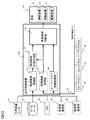
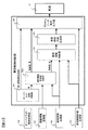
- FIG. 1 is a block diagram of a vehicle travel control apparatus according to the present embodiment.
- the travel control device 100 includes an ambient environment recognition unit 101, a vehicle information acquisition unit 102, a vehicle control plan generation unit 103, an override information acquisition unit 104, and a vehicle control determination unit 105.
- the vehicle 110 includes a steering device 111, a braking device 112, and a driving device 113.
- the steering device 111 controls steering of the vehicle according to a control command value calculated by the travel control device 100, and the braking device 112
- the driving device 113 controls driving of the vehicle.
- Ambient environment recognition unit 101 recognizes obstacles and lanes around the vehicle from external recognition sensor 01, road shape information from database 02, GPS (Global Positioning System) 03, inter-vehicle communication unit 04, road-to-vehicle communication unit Acquire information such as the vehicle position, vehicle speed, vehicle direction, etc. according to 05, information such as relative position and relative speed with other traffic participants, and grasp the surrounding environment for determining the vehicle traveling direction And a function of transmitting to the vehicle control plan generating unit 103.
- GPS Global Positioning System
- the external environment recognition sensor 01 may be constituted by a sensor capable of recognizing obstacles, lanes, signals, etc. around the vehicle such as a stereo camera, a millimeter wave radar, a laser radar, and an infrared sensor.
- the vehicle information acquisition unit 102 collects vehicle behavior information such as own vehicle speed (wheel speed), yaw rate, longitudinal acceleration, and lateral acceleration from ECUs equipped with sensors such as a brake ECU 06, an engine ECU 07, and a power steering ECU 08. A function of transmitting to the generation unit 103 and the vehicle control determination unit 105 is provided.
- the vehicle control plan generation unit 103 has a function of generating a traveling track of the host vehicle based on information from the surrounding environment recognition unit 101 and the vehicle information acquisition unit 102 and transmitting it to the vehicle control determination unit 105. .
- the override information acquisition unit 104 collects driver operation information such as an accelerator operation amount, a brake operation amount, and a steering operation amount from ECUs including sensors such as a brake ECU 06, an engine ECU 07, and a power steering ECU 08, and transmits the collected information to the vehicle control determination unit 105. It has a function to do.
- the vehicle communication bus 09 performs transmission and reception using CAN (Controller (Area Network) that is generally used as an in-vehicle network.
- CAN Controller (Area Network) that is generally used as an in-vehicle network.
- the vehicle control determination unit 105 calculates a steering command value, a braking command value, and a drive command value based on information of the vehicle information acquisition unit 102, the vehicle control plan generation unit 103, and the override information acquisition unit 104.
- the vehicle 110 has a function of transmitting each command value to the steering device 111, the braking device 112, and the drive device 113 provided in the vehicle 110.
- the vehicle control determination unit 105 includes a ROM (Read (Memory) for storing a travel control algorithm, a CPU (Central Processing Unit) for executing various arithmetic processes, a RAM (Random Access Memory) for storing calculation results, and the like. Composed. A detailed internal configuration of the vehicle control determination unit 105 will be described below with reference to FIG.
- the steering device 111 may be configured to control the steering angle by hydraulic power steering, electric power steering, or the like based on the steering command value from the vehicle control determination unit 105.
- the braking device 112 may be configured to control the braking force by a hydraulic brake, an electric rake or the like based on the braking command value from the vehicle control determination unit 105.
- the drive device 113 controls the drive force by an external drive command using an engine or a motor that can control the engine torque with an electric throttle or the like. It may be configured with a powertrain system that can
- the travel control device 100, the steering device 111, the braking device 112, and the drive device 113 are described as separate devices.
- the travel control device 100 of the vehicle and each device are described.
- the braking device 112 and the driving device 113) are combined into one device, or only the vehicle travel control device 100 and the steering device 111 (the braking device 112 and the driving device 113 may be combined) into one device. It is also possible.
- information transmission between the vehicle control determination unit 105 and the vehicle is performed using CAN, which is generally used as an in-vehicle network.
- FIG. 2 is an internal block diagram of the vehicle control determination unit 105.
- illustration of the CPU, RAM, and the like is omitted.
- the override presence / absence determination unit 201 determines whether or not there is an override by the driver based on the driver operation amount acquired by the override information acquisition unit 104.
- the actuator command output unit 204 causes the vehicle control plan generation unit 103 to travel (no correction) as it is according to the track generated by the vehicle control plan generation unit 103.
- the steering device 111, the braking device 112, and the driving device 113 provided in the vehicle 110 are controlled in accordance with the steering command, the braking command, and the driving command that are set and output.
- the vehicle behavior determination unit 202 and the vehicle control content determination unit 203 provide the steering device 111, the braking device 112, and the drive device provided in the vehicle 110.
- the control command value to 113 is corrected and output from the actuator command output unit 204.
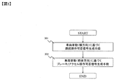
- the internal processing of the vehicle behavior determination unit 202 is shown in FIG.
- the vehicle behavior determination unit 202 performs a process (301) for generating a steering operation propriety signal based on the vehicle behavior in the lateral direction of the vehicle and a process (302) for generating a brake / accelerator operation propriety signal based on the vehicle behavior in the vehicle longitudinal direction.
- the vehicle behavior state is determined, and it is determined whether or not intervention of each operation is possible.
- Table 1 shows output signals as a result of the determination made by the vehicle behavior determination unit 202.
- the vehicle behavior detection unit 202 outputs a vehicle state signal, a steering operation enable / disable signal, and a brake / accelerator operation enable / disable signal.
- “stable” of the vehicle behavior state in the present invention is a state in which the vehicle behavior is not disturbed by the override by the driver, and “unstable” means that the vehicle behavior may be disturbed by the override by the driver. Alternatively, the vehicle behavior is already disturbed.
- the vehicle state signal in Table 1 is determined by the vehicle behavior determination result in the steering operation propriety signal generation unit 301 based on the vehicle behavior (lateral direction) and the brake / accelerator operation propriety signal generation unit 302 based on the vehicle behavior (front-rear direction). .
- the steering operation propriety signal is determined based on the vehicle behavior determination result of the steering operation propriety signal generation means 301 based on the vehicle behavior (lateral direction).
- the brake / accelerator operation enable / disable signal is determined based on the vehicle behavior judgment result of the brake / accelerator operation enable / disable operation signal generation means 302 based on the vehicle behavior (front-rear direction).
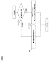
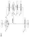
- FIG. 4 shows an embodiment of the steering operation propriety signal generation means 301 based on vehicle behavior (lateral direction).
- a target yaw rate is calculated based on vehicle lateral movement information (steering speed, yaw rate, lateral acceleration, lateral jerk, etc.) obtained from the vehicle information acquisition unit 102 and a general vehicle model.
- step 402 the difference S_yaw between the target yaw rate and the actual yaw rate is calculated.
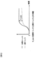
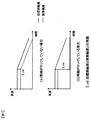
- FIG. 5 shows an example of the state of deviation between the target yaw rate and the actual yaw rate.
- step 403 the process branches depending on the difference S_yaw between the target yaw rate calculated in step 402 and the actual yaw rate.
- the branch determination threshold value may be a fixed value determined by the vehicle type, or may be dynamically switched according to the vehicle state or the driving scene.
- step 403 If the difference S_yaw between the target yaw rate and the actual yaw rate is large (greater than an arbitrary threshold value) in step 403, it is determined that the vehicle behavior in the lateral direction of the vehicle is unstable and the vehicle state signal is set to “unstable” (step 404).
- the steering operation propriety signal is set to “impossible” (step 405).
- the reason why the vehicle state signal is set to “unstable” and the steering operation enable / disable signal is set to “impossible” is that the vehicle behavior becomes “unstable” in the future because the yaw response of the vehicle is delayed with respect to the steering command. This is to prevent a situation in which the vehicle behavior further diverges due to the override by the driver.
- step 403 if the difference S_yaw between the target yaw rate and the actual yaw rate is small (below an arbitrary threshold value) in step 403, the vehicle yaw is responding to the steering command. It is determined that the vehicle behavior is not disturbed even when the override is performed, the vehicle state signal is set to “stable” (step 406), and the steering operation propriety signal is set to “permitted” (step 407).
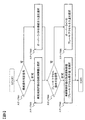
- FIG. 6 shows an example of a brake / accelerator operation enable / disable signal generating means 302 based on vehicle behavior (front-rear direction).
- a target wheel speed is calculated based on vehicle longitudinal movement information (engine torque, accelerator opening, wheel speed, longitudinal acceleration, etc.) obtained from the vehicle information acquisition unit 102 and a general vehicle model.
- vehicle longitudinal movement information engine torque, accelerator opening, wheel speed, longitudinal acceleration, etc.
- step 602 the difference S_vel between the target wheel speed and the actual wheel speed is calculated.
- FIG. 7 shows an example of the difference between the target wheel speed and the actual wheel speed when the wheel is not locked (FIG. 7 (a)) and when the wheel is locked (FIG. 7 (b)).
- step 603 the process branches depending on the difference S_vel between the target wheel speed calculated in step 602 and the actual wheel speed.
- the branch determination threshold value may be a fixed value determined by the vehicle type, or may be dynamically switched according to the vehicle state or the driving scene.
- step 603 If the difference S_vel between the target wheel speed and the actual wheel speed is large (greater than an arbitrary threshold value) in step 603, the vehicle behavior in the vehicle front-rear direction is assumed to be unstable and the vehicle state signal is set to “unstable” ( Then, the brake / accelerator operation enable / disable signal is set to “impossible” (step 605).
- the vehicle state signal is set to “unstable” and the brake / accelerator operation enable / disable signal is set to “impossible” is that the actual wheel speed is suddenly deviated from the target wheel speed as shown in FIG. For this reason, it is considered that the behavior in the vehicle longitudinal direction becomes “unstable” in the future, that is, acceleration / deceleration control cannot be performed.
- each wheel is normally driven in response to the acceleration / deceleration command.
- the vehicle state signal is set to “stable” (step 606), and the brake / accelerator operation enable / disable signal is set to “enabled” (step 607).
- the wheel speed may be measured by a wheel to which the braking / driving force is transmitted.
- the wheel speed may be measured with only one wheel, or with two to four wheels.
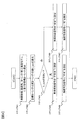
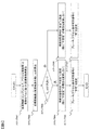
- FIG. 8 is a diagram showing a processing flow of the vehicle control content determination unit 203.
- step 801 vehicle state determination unit
- the subsequent processing is branched depending on whether the vehicle state signal output from the vehicle behavior determination unit 202 is “stable” or “unstable”.
- step 801 If the vehicle state becomes “stable” in step 801, the driver is allowed to override and the driver's operation intervention amount is selected (step 802).
- the vehicle control plan correction unit 803 is based on the contents of the steering operation enable / disable signal and the brake / accelerator operation enable / disable signal determined by the vehicle behavior determining unit 202. Then, the control amount of the vehicle control plan is corrected.
- FIG. 9 is a diagram showing a processing flow of the vehicle control plan correction unit 803.
- Steps 901 and 904 are operations that can be intervened by a steering operation availability signal and a brake / accelerator operation availability signal output from the vehicle behavior determination unit 202. Whether or not there is.
- an override intervention amount is selected as a control amount of the vehicle control plan in step 902 and is selected as an output command to the steering device.
- step 901 if it is determined as “impossible” in step 901, the driver's override is not selected in step 903, and the control amount of the original vehicle control plan is selected as it is as an output command to the steering device. If it is determined in step 904 that the steering propriety signal is “permitted”, an override intervention amount is selected as a control amount of the vehicle control plan in step 906 and is selected as an output command to the braking device / driving device.
- step 904 determines whether the override by the driver is not selected in step 905 or not selected in step 905. If it is determined in step 904 that “NO”, the override by the driver is not selected in step 905, and the control amount of the original vehicle control plan is selected as an output command to the braking device / drive device as it is.
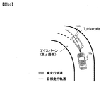
- FIG. 10 describes a scene in which the vehicle 110a during automatic driving passes on an ice burn (low ⁇ road surface) while traveling on a curved road.
- the vehicle 110a during automatic driving travels on an ice burn (low ⁇ road surface), and as a result, the target calculated by the vehicle control plan generation unit 103 based on the curve curvature information obtained from the surrounding environment recognition unit 101. It is assumed that the actual traveling track (solid line in FIG. 10) has an understeer tendency with respect to the traveling track (broken line in FIG. 10).
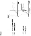
- FIG. 11 is a diagram showing the steering angle and the yaw rate in time series when the vehicle 110a during automatic driving shown in FIG. 10 travels on a curved road. However, the origin is the steering start timing.
- the override information acquisition unit 104 acquires an override by steering.
- the description of the vehicle behavior determination in the longitudinal direction of the vehicle is not described. However, if the brake operation or the accelerator operation is overridden in addition to the steering operation, the vehicle behavior in the vehicle behavior determination unit 202 is determined.
- a brake / accelerator operation enable / disable signal is determined based on the result of the brake / accelerator operation enable / disable signal generation means 302 based on (front-rear direction).
- Example 2 (Example 2 of travel control device) As Example 2, an emergency avoidance scene shown in FIG. 12 will be described.
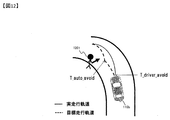
- FIG. 12 shows a scene in which the obstacle 1201 suddenly jumps out to the road side while the vehicle 110b during automatic driving is running on the curve of the dry road surface.
- T_driver_avoid represents a timing when the driver has performed an override
- T_auto_avoid represents a timing at which steering avoidance planned by the vehicle control plan generation unit 103 for automatic driving is scheduled to start.
- the vehicle 110b during automatic driving is a curved road with respect to the target travel path (broken line in FIG. 12) calculated by the vehicle control plan generation unit 103 based on the curve curvature information obtained from the surrounding environment recognition unit 101.
- an obstacle 1201 (pedestrian, bicycle, motorcycle, etc.) suddenly jumps out toward the target trajectory of the vehicle 110b and corrects the target trajectory at the timing T_auto_avoid shown in FIG. Plan to avoid the problem.
- an example in a scene in which the driver cannot wait for collision avoidance in the automatic driving based on the vehicle control plan and starts collision avoidance by his steering operation or brake operation at the timing T_driver_avoid shown in FIG. 12 will be described.
- the surrounding environment recognition unit 101 In addition to the road shape in the traveling direction, the surrounding environment recognition unit 101 always monitors the presence / absence of an obstacle in the traveling direction using the external recognition sensor 01. If an obstacle 1201 appears in the middle of the curve, the size of the obstacle 1201 is displayed. And movement (moving speed, moving direction) are also detected. The vehicle control plan generation unit 103 calculates an avoidance route in accordance with the size and movement of the obstacle 1201.
- FIG. 13 is a diagram showing the steering angle and yaw rate of the vehicle 110b in the embodiment of FIG. 12 in time series. However, the origin is the steering start timing.
- the steering angle graph shows the steering angle that was planned to be implemented in the vehicle control plan if the driver wanted to override the steering operation.
- the driver senses the danger of colliding with the obstacle 1201 that has popped out, and starts the collision avoidance by performing the steering operation and the brake operation by the driver himself.
- the override information acquisition unit 104 acquires an override by a steering operation or a brake operation.
- the override is determined to be “present” based on the result of the override presence / absence determination unit 201 based on the override information acquisition unit 104. Judging the vehicle behavior state in the vehicle front-rear and lateral directions.
- FIG. 7 (a) As a vehicle behavior state in the longitudinal direction of the vehicle, if the brake operation is performed on a dry road, the brake operation is permitted unless the brake is applied so hard that the wheels are locked. The signal becomes “OK”. On the other hand, as shown in FIG. 7B, when the wheel is locked, the brake operation propriety signal is “impossible”. In the second embodiment, it will be described that the brake operation propriety signal is “permitted”.
- the vehicle behavior state signal becomes “stable”.
- the vehicle state signal output from the vehicle behavior determination unit 202 is “stable” in the vehicle control content determination unit 203, all steering operations and braking operations of the driver are permitted, and steering based on the original vehicle control plan is performed.
- a control amount obtained by adding the driver's intervention amount is output to each actuator.
- the present invention is not limited to a curved road, and is applied when an override is performed by a driver in various situations such as a straight road and an intersection. It is.
- the configuration of the traveling control device described in the first and second embodiments described above determines whether or not the override can be performed based on the state of the vehicle behavior when the driver is overridden. Even if the condition is stable, depending on the surrounding environment, there is a possibility of danger to the surroundings due to driver override.
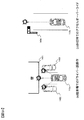
- FIG. 14 is a diagram showing an example of a scene that causes danger depending on an override even if the vehicle behavior state is stable.
- a traffic light 1404 in the direction of travel may be red (as shown in FIG. (Including signs other than traffic lights 1404), the driver of the vehicle 110d stepped on the accelerator for an unexpected reason (not aware of red color, unconscious due to sudden illness, etc.) It is a scene where accidents occur at intersections, construction sites, railroad crossings, etc. that will appear in the destination.
- the hardware configuration of the vehicle can be implemented with the same configuration as in FIG. 1, but the third embodiment is realized by configuring the internal processing of the vehicle control determination unit 105 as shown in FIG. Can do.
- the surrounding environment risk determination unit 1502 determines whether or not the vehicle control plan is prioritized.
- FIG. 16 shows a flowchart describing detailed processing of the ambient environment risk determination unit 1502 in the vehicle control determination unit in the embodiment 3 of the present invention.
- the own vehicle surrounding risk calculation unit 1601 calculates the degree of danger around the own vehicle, and in step 1602 determines whether or not the vehicle control plan has priority.
- the own vehicle surroundings risk calculation unit 1601 is configured to detect surrounding obstacles (vehicles, pedestrians, bicycles, motorcycles, etc.), lanes, traffic lights, intersections, construction sites, railroad crossings, etc. obtained from the surrounding environment recognition unit 101.
- the risk S_d around the host vehicle is calculated by inputting information such as presence / absence, and it is determined in step 1602 whether or not to prioritize the vehicle control plan based on the calculation result.
- an area with an obstacle observed by the external recognition device sets the risk S_d to “high” and can be observed by the external recognition device.
- the risk level S_d is set to “low” in the area where there is no obstacle. Also, the risk S_d of the area that cannot be observed at the blind spot such as an obstacle is set to “medium”.
- the course of the vehicle is predicted based on the driver's operation amount and vehicle information (vehicle speed, steering angle, yaw rate, etc.) acquired by the override information acquisition unit 104, and the prediction
- vehicle information vehicle speed, steering angle, yaw rate, etc.
- the driver's operation is determined as an erroneous operation, and in step 1602, the vehicle control plan is determined as a priority scene.
- the threshold value Th_d can be set arbitrarily.
- Th_d may be fixedly set to “high”, or may be set such that Th_d is variably switched according to the time zone (commuting time, school attendance, etc.) and the traveling scene.
- step 1602 If it is determined in step 1602 that the vehicle control plan is to be prioritized, the target trajectory calculated by the vehicle control plan generation unit 103, the control command for steering, accelerator, brake, etc. for the target trajectory is output without correction.
- step 1602 the subsequent processing when it is determined that the vehicle control plan is not prioritized is the same as the processing described in the first and second embodiments, and thus the description is omitted.
- ACC preceding vehicle following control
- LLS lane keeping assist control
- a mechanism may be provided that detects a vehicle behavior or a scene that does not allow overriding in advance, and notifies the driver of the fact when the vehicle behavior is unstable or a scene that does not allow overriding.
- the vehicle control plan generation unit described above has been described by taking up automatic driving (controlling acceleration / deceleration, steering, etc. along the target travel path).
- it may be an Adaptive Cruise Control (ACC), an emergency automatic brake, a lane keep assist system, or a vehicle control plan combining these two or more controls.
- ACC Adaptive Cruise Control
- emergency automatic brake a lane keep assist system
- vehicle control plan combining these two or more controls.
- each of the above-described configurations, functions, processing units, and the like may be realized in hardware by designing a part or all of them, for example, with an integrated circuit.
- Each of the above-described configurations, functions, and the like may be realized by software by the processor interpreting and executing a program that realizes each function.
- Information such as programs, tables, and files that realize each function can be stored in a recording device such as a memory, a hard disk, or an SSD (Solid State Drive), or a recording medium such as an IC card, an SD card, or a DVD.
- Vehicle control determination unit 110 vehicle (vehicle having an automatic driving function) 110a Vehicle (vehicle with automatic driving function) 110b Vehicle (vehicle with automatic driving function) 110c Vehicle (Vehicle with automatic driving function) 110d vehicle (vehicle with automatic driving function) 111 Steering device 112 Braking device 113 Drive device 202 Vehicle behavior determination unit 203 Vehicle control content determination unit 204 Own vehicle surroundings risk calculation unit 803 Vehicle control plan correction unit 1001 Vehicle 110a slipped with respect to the target track 1201 Jump-out obstacle (pedestrian) 1401 Wall 1402 Parked vehicle 1403 Parked vehicle 1404 Traffic light
Landscapes
- Engineering & Computer Science (AREA)
- Automation & Control Theory (AREA)
- Transportation (AREA)
- Mechanical Engineering (AREA)
- Physics & Mathematics (AREA)
- Human Computer Interaction (AREA)
- General Physics & Mathematics (AREA)
- Aviation & Aerospace Engineering (AREA)
- Remote Sensing (AREA)
- Radar, Positioning & Navigation (AREA)
- Mathematical Physics (AREA)
- Chemical & Material Sciences (AREA)
- Combustion & Propulsion (AREA)
- Control Of Driving Devices And Active Controlling Of Vehicle (AREA)
Abstract
本発明は、ドライバーによるオーバーライドが行われた際の車両挙動に応じて、オーバーライドを適切に制御することで、車両挙動が不安定とならないように車両を制御することができる車両の走行制御装置を提供する。本発明の走行制御装置は、車両の制御計画を生成する車両制御計画生成部103と、車両に対するドライバーの操作内容を取得する操作内容取得部104と、制御計画とドライバーの操作内容とに基づいて車両制御内容を決定する車両制御判断部105と、車両の挙動を判断する車両挙動判断部202と、車両挙動判断部202で判断した車両の挙動に基づいて、ドライバーの操作内容を車両制御計画より優先させるか否かを決定する車両制御内容決定部203と、を備える。
Description
本発明は、走行制御装置に関する。
自動車におけるADAS(先進運転支援システム)及び自動運転関連技術の開発が、近年、急速に進められている。運転操作の一部を自動化する機能として、アダプティブクルーズコントロール、レーンキープアシストシステム、緊急自動ブレーキ等が実用化に至っている。
これらの機能はいずれも制御中にドライバーの操作介入(オーバーライド)を許容するシステムとなっており、オーバーライドが行われた際の車両制御に関し、特許文献1ではドライバーがオーバーライドした場合に自動運転から手動運転に切り替える自動運転車両を制御する自動運転車両制御装置が開示されている。また、特許文献2ではドライバーのオーバーライドに基づいて、目標の車両挙動を補正する車両制御装置が開示されている。
近年、高齢者や運転が不慣れなドライバーの運転誤操作による交通事故が多く発生しており、自動運転の早期開発が求められている。
一方で、自動運転が高度化(自動運転レべルが高くなる)するに伴い、走行中におけるドライバーの運転に対する注意力・集中力は低下することが考えられるため、突発的なシチュエーションにおいてドライバーの操作介入行動が大きな動作となり、走行状況によっては車両挙動を不安定にしてしまう可能性がある。
現在の自動運転のコンセプトとしてドライバーによるオーバーライドは全てにおいて優先しており、車両の挙動安定度合いに応じてオーバーライドと自動運転による軌道制御の何れかを選択するものであり、オーバーライド時点での車両挙動の状態に応じてオーバーライド自体の介入を制御することは実施されていない。
そこで、本発明は、ドライバーによるオーバーライドが行われた際の車両挙動に応じて、オーバーライドを適切に制御することで、車両挙動が不安定とならないように車両を制御することができる車両の走行制御装置を提供することを目的とする。
上記課題を解決するために、本発明の走行制御装置は、車両の制御計画を生成する車両制御計画生成部と、前記車両に対するドライバーの操作内容を取得する操作内容取得部と、前記制御計画と前記ドライバーの操作内容とに基づいて車両制御内容を決定する車両制御判断部と、前記車両の挙動を判断する車両挙動判断部と、該車両挙動判断部で判断した前記車両の挙動に基づいて、前記ドライバーの操作内容を前記車両制御計画より優先させるか否かを決定する車両制御内容決定部と、を有する構成とする。
本発明によれば、ドライバーによるオーバーライドが行われた際の車両挙動に応じて、オーバーライドを適切に制御することで、車両挙動が不安定とならないように車両を制御することができる車両の走行制御装置を提供することができる。
以下に、図面を参照して本発明の車両の走行制御装置の実施形態について説明する。
図1は、本実施の形態に係る車両の走行制御装置のブロック図である。図1において、走行制御装置100は、周囲環境認識部101、車両情報取得部102、車両制御計画生成部103、オーバーライド情報取得部104、および車両制御判断部105を備えている。
図1は、本実施の形態に係る車両の走行制御装置のブロック図である。図1において、走行制御装置100は、周囲環境認識部101、車両情報取得部102、車両制御計画生成部103、オーバーライド情報取得部104、および車両制御判断部105を備えている。
車両110は、操舵装置111、制動装置112、駆動装置113を有し、走行制御装置100によって演算された制御指令値に応じて、操舵装置111では車両の操舵を制御し、制動装置112では車両の制動を制御し、駆動装置113では車両の駆動を制御する。
周囲環境認識部101は、外界認識センサ01から自車周辺の障害物や車線の認識情報、データベース02からは道路形状情報、GPS(Global Positioning System)03や車車間通信部04、路車間通信部05による自車位置や自車速、自車方位等の情報、他交通参加者との相対位置や相対速度等の情報を取得し、自車進行方向を決定するための自車周囲環境を把握し、車両制御計画生成部103に送信する機能を備えている。
なお、外界認識センサ01はステレオカメラや、ミリ波レーダ、レーザレーダ、赤外線センサ等の自車周囲の障害物や車線、信号等を認識することができるセンサで構成するとよい。
車両情報取得部102は、ブレーキECU06やエンジンECU07、パワステECU08等のセンサを備えたECUから自車速(車輪速)やヨーレイト、前後加速度、横加速度などの車両の挙動情報を収集し、車両制御計画生成部103や車両制御判断部105に送信する機能を備えている。
車両制御計画生成部103は、前記周囲環境認識部101と前記車両情報取得部102からの情報に基づいて、自車両の走行軌道を生成し、車両制御判断部105に送信する機能を備えている。
オーバーライド情報取得部104は、ブレーキECU06やエンジンECU07、パワステECU08等のセンサを備えたECUからアクセル操作量やブレーキ操作量、ステア操作量といったドライバーの操作情報を収集し、車両制御判断部105に送信する機能を備えている。
ただし、本実施の形態において、車両系通信バス09は車載用ネットワークとして一般に利用されているCAN(Controller Area Network)を利用して送受信を行う。
車両制御判断部105は、前記車両情報取得部102と、前記車両制御計画生成部103と、前記オーバーライド情報取得部104の情報に基づいて、操舵指令値や制動指令値、駆動指令値を演算し、車両110に備わる操舵装置111や制動装置112、駆動装置113へ各指令値を送信する機能を備えている。
なお、車両制御判断部105は、走行制御アルゴリズムを格納するためのROM(Read Only Memory)や各種演算処理を実行するCPU(Central Processing Unit)、演算結果を格納するRAM(Random Access Memory)等から構成される。車両制御判断部105の詳細な内部構成は図2を参照して以下で説明する。
操舵装置111は、前記車両制御判断部105からの操舵指令値に基づいて、油圧パワーステアリング、電動パワーステアリング等で操舵角を制御する構成とするとよい。
制動装置112は、前記車両制御判断部105からの制動指令値に基づいて、油圧ブレーキや電動レーキ等で制動力を制御する構成とするとよい。
駆動装置113は、前記車両制御判断部105からの駆動指令値に基づいて、電動スロットル等でエンジントルクを制御することができるエンジンや、モータ等で外部からの駆動指令により駆動力を制御することができるパワートレインシステム等で構成するとよい。
なお、本実施の形態では、走行制御装置100と、操舵装置111、制動装置112および駆動装置113を別装置として記載しているが、例えば、車両の走行制御装置100と各装置(操舵装置111、制動装置112、駆動装置113)を組み合わせて一つの装置とすることや、車両の走行制御装置100と操舵装置111のみ(制動装置112や駆動装置113でもよい)を組み合わせて一つの装置とすることも可能である。
また、本実施の形態では、車両制御判断部105と車両との情報伝達では車載用ネットワークとして一般に利用されているCANを利用して送受信を行う。
次に、車両制御判断部105の内部構成について説明する。
1図2は、車両制御判断部105の内部ブロック図である。なお、図2において、CPUやRAM等の図示は省略している。
1図2は、車両制御判断部105の内部ブロック図である。なお、図2において、CPUやRAM等の図示は省略している。
まず、オーバーライド有無判断部201は、前記オーバーライド情報取得部104で取得されたドライバー操作量に基づいてドライバーによるオーバーライドの有無を判断する。
前記オーバーライド有無判断部201において、ドライバーによるオーバーライドが「無」と判断された場合は前記車両制御計画生成部103で生成される軌道にそのまま従って走行(補正無し)するようにアクチュエータ指令出力部204で設定され、出力される操舵指令、制動指令、駆動指令に従って車両110に備わる操舵装置111と、制動装置112と、駆動装置113を制御する。
前記オーバーライド有無判断部201において、ドライバーによるオーバーライドが「有」と判断された場合は車両挙動判断部202と車両制御内容決定部203により車両110に備わる操舵装置111と、制動装置112と、駆動装置113への制御指令値を補正し、アクチュエータ指令出力部204から出力する。
車両挙動判断部202の内部処理を図3に示す。
車両挙動判断部202では、車両横方向の車両挙動に基づき操舵操作可否信号を生成する処理(301)と車両前後方向の車両挙動に基づきブレーキ/アクセル操作可否信号を生成する処理(302)を行うことで車両挙動状態を判断し、各操作の介入が可能か否かを判断する。
車両挙動判断部202で判断された結果の出力信号を表1に示す。
車両挙動判断部202では、車両横方向の車両挙動に基づき操舵操作可否信号を生成する処理(301)と車両前後方向の車両挙動に基づきブレーキ/アクセル操作可否信号を生成する処理(302)を行うことで車両挙動状態を判断し、各操作の介入が可能か否かを判断する。
車両挙動判断部202で判断された結果の出力信号を表1に示す。

表1に示すように、車両挙動検知部202は、車両状態信号と操舵操作可否信号とブレーキ/アクセル操作可否信号を出力する。ここで、本発明における車両挙動状態の「安定」とは、ドライバーによるオーバーライドで車両挙動が乱れることがない状態とし、「不安定」とは、ドライバーによるオーバーライドで車両挙動が乱れる可能性がある、または既に車両挙動が乱れている状態とする。
表1における車両状態信号は、車両挙動(横方向)に基づく操舵操作可否信号生成手段301や車両挙動(前後方向)に基づくブレーキ/アクセル操作可否信号生成手段302における車両挙動判断結果によって決定される。
操舵操作可否信号は、車両挙動(横方向)に基づく操舵操作可否信号生成手段301の車両挙動判断結果に基づいて可否を決定される。
ブレーキ/アクセル操作可否信号は、車両挙動(前後方向)に基づくブレーキ/アクセル操作可否操作可否信号生成手段302の車両挙動判断結果に基づいて可否を決定される。
図4は車両挙動(横方向)に基づく操舵操作可否信号生成手段301の一実施例である。
まず、ステップ401において車両情報取得部102から得られる車両横運動情報(操舵速度、ヨーレイト、横加速度、横加加速度など)と一般的な車両モデルに基づいて目標ヨーレイトを算出する。
次にステップ402において目標ヨーレイトと実ヨーレイトの差S_yawを算出する。
ここで、図5に目標ヨーレイトと実ヨーレイトの乖離の様子を表した例を示す。
ステップ403ではステップ402で算出した目標ヨーレイトと実ヨーレイトの差S_yawの大きさによって処理を分岐させる。ここで、分岐判断の閾値は車種によって決まるような固定値としてもよいし、車両状態や走行シーンに応じて動的に切り替えるものとしてもよい。
ステップ403で目標ヨーレイトと実ヨーレイトの差S_yawが大きい(任意の閾値以上となる)場合は、車両横方向の車両挙動が不安定状態であるとし車両状態信号を「不安定」に設定(ステップ404)し、操舵操作可否信号を「不可」に設定(ステップ405)する。車両状態信号を「不安定」、操舵操作可否信号を「不可」に設定する理由として、操舵指令に対して車両のヨー応答が遅れていることから将来車両挙動が「不安定」になることが考えられるため、ドライバーによるオーバーライドが加わることで更に車両挙動が発散してしまう事態を防ぐためである。
一方、ステップ403にて目標ヨーレイトと実ヨーレイトの差S_yawが小さい(任意の閾値以下となる)の場合は、操舵指令に対して車両のヨーが応答している状態であるので、その時にドライバーによるオーバーライドが実施されても車両挙動が乱れることはないと判断し、車両状態信号を「安定」に設定(ステップ406)し、操舵操作可否信号を「可」に設定(ステップ407)する。
図6は車両挙動(前後方向)に基づくブレーキ/アクセル操作可否信号生成手段302の一実施例である。
まず、ステップ601において車両情報取得部102から得られる車両前後運動情報(エンジントルク、アクセル開度、車輪速、前後加速度など)と一般的な車両モデルに基づいて目標車輪速を算出する。
次にステップ602において目標車輪速と実車輪速の差S_velを算出する。
ここで、図7に車輪がロックしない場合(図7(a))とロックする場合(図7(b))の目標車輪速と実車輪速の乖離の様子を表した例を示す。
ステップ603ではステップ602で算出した目標車輪速と実車輪速の差S_velの大きさによって処理を分岐させる。ここで、分岐判断の閾値は車種によって決まるような固定値としてもよいし、車両状態や走行シーンに応じて動的に切り替えるものとしてもよい。
ステップ603で目標車輪速と実車輪速の差S_velが大きい(任意の閾値以上となる)場合は、車両前後方向の車両挙動が不安定状態であるとし車両状態信号を「不安定」に設定(ステップ604)し、ブレーキ/アクセル操作可否信号を「不可」に設定(ステップ605)する。車両状態信号を「不安定」、ブレーキ/アクセル操作可否信号を「不可」に設定する理由として、図7(b)に示すように、実車輪速が目標車輪速に対して突然乖離していることから将来車両前後方向の挙動が「不安定」になる、つまり加減速制御ができないことが考えられるため、ドライバーによるオーバーライドが加わることで更に車両挙動が乱れてしまう事態を防ぐためである。例えば、路面摩擦係数μの低い路面(アイスバーンなど)を走行中に自動運転やドライバーにより強いブレーキ/アクセル操作が行われると、車輪がロックしてしまい、車両は滑って移動し続けている状態で、車両前後方向の車両挙動が不安定と言える。
一方、ステップ603にて目標車輪速と実車輪速の差S_velが小さい(任意の閾値以下となる)の場合は、加減速指令に対して正常に各車輪が駆動している状態であるので、その時にドライバーによるオーバーライドが実施されても車両挙動が乱れることはないと判断し、車両状態信号を「安定」に設定(ステップ606)し、ブレーキ/アクセル操作可否信号を「可」に設定(ステップ607)する。
ここで、車輪速を使った車両挙動判断手法を用いる場合、車輪速は制駆動力が伝達される輪で計測するとよい。また、車輪速の計測は1輪のみで行ってもよいし、2輪~4輪で計測を行ってもよい。
図8は車両制御内容決定部203の処理フローを示した図である。
まず、ステップ801(車両状態判断部)では前記車両挙動判断部202から出力される車両状態信号が「安定」か「不安定」かによってその後の処理を分岐させる。
前記ステップ801で車両状態が「安定」となる場合は、ドライバーのオーバーライドを許可し、ドライバーの操作介入量を選択する(ステップ802)。
前記ステップ801で車両状態が「不安定」となる場合は、車両制御計画補正部803にて、前記車両挙動判断部202で判断された操舵操作可否信号とブレーキ/アクセル操作可否信号の内容に基づいて、車両制御計画の制御量を補正する。
図9は車両制御計画補正部803の処理フローを示した図である。
ステップ901とステップ904(これらのステップを総称して介入可能操作有無判断部とする)は、前記車両挙動判断部202から出力される操舵操作可否信号とブレーキ/アクセル操作可否信号で介入可能な操作の有無を判別する。
ステップ901で操舵可否信号が「可」と判別された場合は、ステップ902で車両制御計画の制御量としてオーバーライドの介入量を選択し、操舵装置への出力指令として選択する。
一方、ステップ901で「不可」と判別された場合は、ステップ903でドライバーによるオーバーライドを選択せず、元の車両制御計画の制御量をそのまま操舵装置への出力指令として選択する。
ステップ904で操舵可否信号が「可」と判別された場合は、ステップ906で車両制御計画の制御量としてオーバーライドの介入量を選択し、制動装置/駆動装置への出力指令として選択する。
ステップ904で操舵可否信号が「可」と判別された場合は、ステップ906で車両制御計画の制御量としてオーバーライドの介入量を選択し、制動装置/駆動装置への出力指令として選択する。
一方、ステップ904で 「不可」と判別された場合は、ステップ905でドライバーによるオーバーライドを選択せず、元の車両制御計画の制御量をそのまま制動装置/駆動装置への出力指令として選択する。
以上の本発明の形態を用いた実施例を以下に記載する。
(走行制御装置の実施例1)
実施例1として、図10は自動運転中の車両110aがカーブ路を走行中にアイスバーン(低μ路面)上を通過するシーンについて記述する。
実施例1として、図10は自動運転中の車両110aがカーブ路を走行中にアイスバーン(低μ路面)上を通過するシーンについて記述する。
具体的には、自動運転中の車両110aはアイスバーン(低μ路面)上を走行した結果、周囲環境認識部101から得られるカーブ曲率情報に基づいて車両制御計画生成部103で演算された目標走行軌道(図10の破線)に対して実走行軌道(図10の実線)はアンダーステア傾向になった場合を想定する。
図11は、図10に示す自動運転中の車両110aがカーブ路を走行した際の操舵角とヨーレイトを時系列で示した図である。ただし、原点は操舵開始のタイミングとする。
図11中に示すタイミングT_driver_slipの時点でドライバーは、自動運転中の車両110aの走行経路がアンダーステア傾向であることを感じ、ドライバー自身でさらに操舵を切り増してオーバーライドを行った。このとき、オーバーライド情報取得部104により操舵によるオーバーライドを取得する。
そして、車両制御判断部105では、オーバーライド情報取得部104の結果からオーバーライド有無判断部201でオーバーライドが「有」と判断されることから車両挙動判断部202でオーバーライドが行われた時点での車両挙動の状態を判断する。
車両110aには図11に示すような実ヨーレイト(図11の破線)が発生していたとする。ドライバーがオーバーライドを実施したタイミングT_driver_slipにおけるヨーレイトに着目すると、目標ヨーレイトと実ヨーレイトの差S_yawが大きいので、この時点でドライバーの操舵操作によるオーバーライドを許可するとその先の車両挙動が大きく乱れていくことが予想されるため、操舵操作可否信号は「不可」と設定され、車両挙動状態信号は「不安定」となる。
本実施例1では車両前後方向の車両挙動判断についての説明は記載しなかったが、もし操舵操作に加えてブレーキ操作やアクセル操作のオーバーライドも実施する場合は、車両挙動判断部202内の車両挙動(前後方向)に基づくブレーキ/アクセル操作可否信号生成手段302の結果に基づいてブレーキ/アクセル操作可否信号が決まる。
次に、車両制御内容決定部203では車両挙動判断部202から出力される車両状態信号が「不安定」であることから、車両制御計画補正部603の処理によって操舵操作によるオーバーライドを加味するか否かを判断する。本実施例1の場合では、操舵操作可否信号が「不可」と設定されていることから、ドライバーの操舵操作によるオーバーライドは受け入れられず、元の車両制御計画による操舵制御量が出力される。
(走行制御装置の実施例2)
実施例2として、図12に示す緊急回避のシーンについて記述する。
実施例2として、図12に示す緊急回避のシーンについて記述する。
図12は自動運転中の車両110bがドライ路面のカーブを走行中に突然障害物1201が車道側に飛び出してきたシーンを表している。図12に示す、T_driver_avoidはドライバーがオーバーライドを行ったタイミング、T_auto_avoidは自動運転の車両制御計画生成部103で計画された操舵回避を開始する予定としていたタイミングを表している。
具体的に、自動運転中の車両110bは、周囲環境認識部101から得られるカーブ曲率情報に基づいて車両制御計画生成部103で演算された目標走行軌道(図12の破線)に対してカーブ路を走行していた途中に、突然、障害物1201(歩行者、自転車、バイク等)が車両110bの目標軌道に向かって飛び出してきて、図12に示すタイミングT_auto_avoidで目標軌道を修正して障害物を回避する走行を計画する。しかし、ドライバーは車両制御計画による自動運転の衝突回避を待ちきれずに、図12に示すタイミングT_driver_avoidで自らの操舵操作やブレーキ操作によって衝突回避を開始した、というシーンにおける実施例を記述する。
周囲環境認識部101では進行方向の道路形状に加えて、常に外界認識センサ01で進行方向の障害物の有無を監視しており、カーブ途中に障害物1201が現れたら、その障害物1201のサイズや動き(移動速度、移動方向)も検出する。障害物1201のサイズや動きに応じて、車両制御計画生成部103では回避経路を演算する。
図13は、図12の実施例における車両110bの操舵角とヨーレイトを時系列で示した図である。ただし、原点は操舵開始のタイミングとする。また、操舵角のグラフに関しては、もしドライバーによる操舵操作によるオーバーライドが行われたかった場合の車両制御計画で実施する予定だった操舵角を示している。
図13中に示すタイミングT_driver_avoidの時点でドライバーは、飛び出してきた障害物1201に衝突してしまう危険を察知し、ドライバー自身で操舵操作やブレーキ操作を行って衝突回避を開始した。このとき、オーバーライド情報取得部104により操舵操作やブレーキ操作によるオーバーライドを取得する。
そして、車両制御判断部105では、オーバーライド情報取得部104に基づいてオーバーライド有無判断部201の結果でオーバーライドが 「有」と判断されることから車両挙動判断部202でオーバーライドが行われた時点での車両前後・横方向の車両挙動状態を判断する。
まず、車両横方向の車両挙動状態として、車両110には図13に示すような実ヨーレイト(図13の破線)が発生していたとする。ドライバーがオーバーライドを実施したタイミングT_driver_avoidにおけるヨーレイトに着目すると、目標ヨーレイトと実ヨーレイトの差S_yawは小さいので、この時点でドライバーの操舵操作によるオーバーライドが介入したとしても車両挙動が乱れることはないと予想されるため、操舵操作可否信号は「可」と設定される。
次に、車両前後方向の車両挙動状態として、図7(a)に示したように、ドライ路においてブレーキ操作を行った場合、車輪がロックする程の強いブレーキをかけない限りは、ブレーキ操作可否信号は「可」となる。一方で図7(b)に示すように、車輪がロックする場合は、ブレーキ操作可否信号は「不可」となる。本実施例2ではブレーキ操作可否信号は「可」になったとして述べていく。
前述したように、本実施例2では操舵操作可否信号とブレーキ操作可否信号は共に「可」であることから車両挙動状態信号は「安定」となる。
次に、車両制御内容決定部203では車両挙動判断部202から出力される車両状態信号が「安定」であることから、ドライバーの操舵操作とブレーキ操作は全て許可され、元の車両制御計画による操舵制御量とブレーキ制御量に加えてドライバーの介入量分を加算した制御量を各アクチュエータへ出力する。
実施例1と実施例2ではカーブ路におけるシーンについて記述したが、本発明はカーブ路に限らず、直線路や交差点等の様々なシチュエーションにおいて、ドライバーによるオーバーライドが行われた際に適用されるものである。
(走行制御装置の実施例3)
前記の実施例1と実施例2で記述した走行制御装置の構成は、ドライバーのオーバーライドが行われたら車両挙動の状態に基づいて、そのオーバーライドの可否を判断していたが、場合によっては車両挙動状態が安定であっても周囲環境によってはドライバーのオーバーライドによって周囲に対して危険を及ぼす可能性もある。
前記の実施例1と実施例2で記述した走行制御装置の構成は、ドライバーのオーバーライドが行われたら車両挙動の状態に基づいて、そのオーバーライドの可否を判断していたが、場合によっては車両挙動状態が安定であっても周囲環境によってはドライバーのオーバーライドによって周囲に対して危険を及ぼす可能性もある。
図14は車両挙動状態が安定であってもオーバーライドによっては危険を及ぼすシーンの例を示した図である。
例えば、図14(a)に示すように、車両110cのドライバーが駐車場での踏み間違い(ブレーキとアクセルを間違える)によって車両挙動としては不安定とはならないが、周囲の車両1402や1403、壁1401、他にも店舗の駐車場であれば多数の歩行者に接触・衝突の危険を及ぼす可能性がある場面や、図14(b)に示すように、進行方向の信号機1404が赤色(車両に停止を指示する標識、信号機1404以外の信号も含む)にも関わらず、車両110dのドライバーが予期せぬ事由(赤色に気づかない、急病により意識不明になる等)でアクセルを踏み込んでしまい、進行先に現れるであろう交差点や工事現場、踏切等での事故が発生してしまう場面である。
そこで本実施例3では、オーバーライドの可否判断において、オーバーライドにより自車周囲に危険が及ぶ可能性があるかないか、という条件も含めた構成について記述する。
車両のハード構成としては、図1と同様の構成で実施することができるが、車両制御判断部105の内部処理を図15に示すような構成とすることで、本実施例3を実現することができる。
図15において、オーバーライド有無判断部201でドライバーによるオーバーライドが 「有」と判断された場合、次に、周囲環境危険度判断部1502にて車両制御計画を優先させるシーンか否かを判断する。
ここで図16には、本実施例3の形態における車両制御判断部内の周囲環境危険度判断部1502の詳細処理を記載したフローチャートを示している。
自車周囲危険度算出部1601にて自車周囲の危険度を算出し、ステップ1602にて車両制御計画を優先させるシーンか否かを判断する。
自車周囲危険度算出部1601は、周囲環境認識部101から得られる周囲の障害物(車両、歩行者、自転車、バイク等)や車線、信号機の灯色状態、交差点や工事現場、踏切等の有無、といった情報を入力として自車周囲の危険度S_dを算出し、その算出結果に基づいてステップ1602で車両制御計画を優先させるか否かを判断する。
自車周囲危険度算出部1601における、自車周囲危険度算出の一例として、外界認識装置で観測された障害物のある領域は危険度S_dを「高」に設定し、外界認識装置の観測可能領域において障害物がない領域は危険度S_dを「低」に設定する。また、障害物等の死角で観測できない領域の危険度S_dは 「中」を設定する。
また、ドライバーによるオーバーライドをドライバーの誤動作と判断するために、オーバーライド情報取得部104で取得したドライバーの各操作量と車両情報(車速、操舵角、ヨーレイト等)から車両の進路を予測し、その予測経路が前記の危険領域(危険度S_dが閾値Th_d以上)を通過する場合には、ドライバーによる操作(オーバーライド)を誤操作と判断し、ステップ1602で車両制御計画を優先させるシーンとして判断する。
ここで、閾値Th_dは任意に設定することができる。例えば固定的にTh_d を「高」に設定してもよく、或いは、時間帯(通退勤や登下校時間など)や走行シーンに応じて変動的にTh_dが切り替わるといった設定でもよい。
ステップ1602において、車両制御計画を優先させると判断した場合には、車両制御計画生成部103で算出される目標軌道、目標軌道に対する操舵、アクセル、ブレーキ等の制御指令を補正することなく出力する。
ステップ1602において、車両制御計画を優先しないと判断した場合のその後の処理については、実施例1と実施例2で記述してきた同様の処理を行うため、記述を割愛する。
以上のように、自動運転中にドライバーが操作介入してきた場合に、その時の車両挙動状態によってドライバーによる操作介入の可否を判断する構成として説明してきたが、本発明は自動運転を搭載しない車両(先行車追従制御(ACC)や車線維持アシスト制御(LKS)などといった運転支援システムを搭載する車)に対しても適用されるものである。
また、本発明を搭載した車両のドライバーがオーバーライドを行ったにも関わらず、その操作が車両に反映されない場合、その車両に不安を与えてしまうことも考えられるため、オーバーライドを許可しない場合には予め、車両挙動やオーバーライドを許容しないシーンを検知しておいて、車両挙動が不安定な場合やオーバーライドを許容しないシーンには、その旨をドライバーにお知らせする機構を設けてもよい。
以上、本発明の実施形態を、図面を用いて記述してきたが、具体的な構成は上記した実施形態に限定されるものではなく、本発明の要旨を逸脱しない範囲における設計変更等があっても、それらは本発明に含まれるものである。例えば、上記した実施形態は本発明を分かり易く説明するために詳細に説明したものであり、必ずしも説明した全ての構成を備えるものに限定されるものではない。また、ある実施形態の構成の一部を他の実施形態の構成に置きかえることが可能であり、また、ある実施形態の構成に他の実施形態の構成を加えることも可能である。また、各実施形態の構成の一部について、他の構成の追加・削除・置換をすることが可能である。
具体的には、これまで上述してきた車両制御計画生成部は自動運転(目標走行軌道に沿うように加減速、操舵等を制御)を取り上げて説明しているが、車両制御計画としては、これ以外にもAdaptive Cruise Control(ACC)や緊急自動ブレーキ、レーンキープアシストシステム等であってもよく、さらには、これら2つ以上の制御を組み合わせた車両制御計画であってもよい。
また、上記の各構成、機能、処理部等は、それらの一部もしくは全部を、例えば集積回路で設計する等によってハードウェアで実現してもよい。また、上記の各構成、機能等は、プロセッサがそれぞれの機能を実現するプログラムを解釈し、実行することにより、ソフトウェアで実現してもよい。各機能を実現するプログラム、テーブル、ファイル等の情報は、メモリやハードディスク、SSD(Solid State Drive)等の記録装置、もしくはICカード、SDカード、DVD等の記録媒体に置くことができる。
01 外界認識センサ
02 データベース
03 GPS(Global Positioning System)
04 車車間通信部
05 路車間通信部
06 ブレーキECU
07 エンジンECU
08 操舵
09 車両系通信バス
100走行制御装置
101 周囲環境認識部
102 車両情報取得部
103 車両制御計画生成部
104 オーバーライド情報取得部(操作内容取得部)
105 車両制御判断部
110 車両(自動運転機能も備える車両)
110a 車両(自動運転機能も備える車両)
110b 車両(自動運転機能も備える車両)
110c 車両(自動運転機能も備える車両)
110d 車両(自動運転機能も備える車両)
111 操舵装置
112 制動装置
113 駆動装置
202 車両挙動判断部
203 車両制御内容決定部
204 自車周囲危険度算出部
803 車両制御計画補正部
1001 目標軌道に対して横滑りした車両110a
1201 飛び出し障害物(歩行者)
1401 壁
1402 駐車車両
1403 駐車車両
1404 信号機
Claims (9)
- 車両の制御計画を生成する車両制御計画生成部と、
前記車両に対するドライバーの操作内容を取得する操作内容取得部と、
前記制御計画と前記ドライバーの操作内容とに基づいて車両制御内容を決定する車両制御判断部と、
前記車両の挙動を判断する車両挙動判断部と、
該車両挙動判断部で判断した前記車両の挙動に基づいて、前記ドライバーの操作内容を前記車両制御計画より優先させるか否かを決定する車両制御内容決定部と、
を備えることを特徴とする走行制御装置。 - 前記車両挙動判断部は、前記車両に対する前後方向の運動と横方向の運動とを判断する、請求項1記載の走行制御装置。
- 前記車両制御内容決定部は、前記ドライバーの操作内容を前記車両制御計画より優先させる場合、前記車両制御計画を補正する車両制御計画補正部を有する、請求項1記載の走行制御装置。
- 前記車両制御内容決定部は、前記車両挙動判断部で判断された前記車両の挙動に基づいて、車両の状態が安定状態か不安定状態かを判断する車両状態判断部を有し、前記車両の状態に基づいて、前記制御計画を補正するか、前記ドライバーの操作内容とするか決定する、請求項3記載の走行制御装置。
- 前記ドライバーの操作内容が検知されて、前記車両の挙動が不安定な状態となった場合、前記車両制御計画生成部が生成する車両制御計画に従って前記車両制御内容を決定する、請求項1乃至4のいずれかに記載の走行制御装置。
- 前記ドライバーの操作内容が検知されて、前記車両の挙動が安定した状態の場合に、前記ドライバーの操作内容に従って前記車両制御内容を決定する、請求項1乃至4のいずれかに記載の走行制御装置。
- 前記車両制御計画補正部は、
前記車両挙動判断部で判断された車両の挙動に基づいて、介入可能な操作の有無を判別する介入可能操作有無判断部を有し、
前記介入可能な操作可の場合、前記車両制御計画を補正し、
前記介入可能な操作不可の場合、前記車両制御計画を出力する、
請求項3記載の走行制御装置。 - 取得した外界情報及び前記ドライバーの操作内容の少なくともいずれかに基づいて、危険度を判断する周囲環境危険度判断部を有し、
前記車両制御内容決定部は、前記車両の挙動と前記危険度に基づいて、前記ドライバーの操作内容を前記車両制御計画より優先させるか否かを決定する、請求項1記載の走行制御装置。 - 前記車両制御内容決定部は、前記危険度が所定値より高い場合、前記車両制御計画を優先する、請求項8記載の走行制御装置。
Priority Applications (3)
| Application Number | Priority Date | Filing Date | Title |
|---|---|---|---|
| JP2019525321A JP7158105B2 (ja) | 2017-06-15 | 2018-06-04 | 走行制御装置 |
| US16/615,693 US20200117192A1 (en) | 2017-06-15 | 2018-06-04 | Travel Control Device |
| DE112018002177.7T DE112018002177T5 (de) | 2017-06-15 | 2018-06-04 | Fahrtsteuervorrichtung |
Applications Claiming Priority (2)
| Application Number | Priority Date | Filing Date | Title |
|---|---|---|---|
| JP2017117342 | 2017-06-15 | ||
| JP2017-117342 | 2017-06-15 |
Publications (1)
| Publication Number | Publication Date |
|---|---|
| WO2018230376A1 true WO2018230376A1 (ja) | 2018-12-20 |
Family
ID=64660549
Family Applications (1)
| Application Number | Title | Priority Date | Filing Date |
|---|---|---|---|
| PCT/JP2018/021311 Ceased WO2018230376A1 (ja) | 2017-06-15 | 2018-06-04 | 走行制御装置 |
Country Status (4)
| Country | Link |
|---|---|
| US (1) | US20200117192A1 (ja) |
| JP (1) | JP7158105B2 (ja) |
| DE (1) | DE112018002177T5 (ja) |
| WO (1) | WO2018230376A1 (ja) |
Cited By (3)
| Publication number | Priority date | Publication date | Assignee | Title |
|---|---|---|---|---|
| JP2020166308A (ja) * | 2019-03-28 | 2020-10-08 | 株式会社アドヴィックス | 運転支援装置 |
| JP2021079904A (ja) * | 2019-11-22 | 2021-05-27 | トヨタ自動車株式会社 | 衝突回避支援装置 |
| US12128883B2 (en) | 2021-06-29 | 2024-10-29 | Honda Motor Co., Ltd. | Driving assistance device, monitoring device, driving assistance method, and storage medium |
Families Citing this family (13)
| Publication number | Priority date | Publication date | Assignee | Title |
|---|---|---|---|---|
| CN111201557B (zh) * | 2017-10-11 | 2022-02-25 | 本田技研工业株式会社 | 车辆控制装置 |
| JP2019156180A (ja) * | 2018-03-13 | 2019-09-19 | 本田技研工業株式会社 | 車両制御装置、車両制御方法、およびプログラム |
| JP6956688B2 (ja) * | 2018-06-28 | 2021-11-02 | 日立建機株式会社 | 作業機械 |
| JP7205761B2 (ja) * | 2019-02-08 | 2023-01-17 | スズキ株式会社 | 車両の走行制御装置 |
| JP7151578B2 (ja) * | 2019-03-25 | 2022-10-12 | トヨタ自動車株式会社 | 車両制御装置 |
| CN115567891B (zh) * | 2019-06-05 | 2025-01-14 | 深圳引望智能技术有限公司 | 自动驾驶信息指示方法、自动驾驶信息获取方法及装置 |
| JP7215391B2 (ja) * | 2019-10-15 | 2023-01-31 | トヨタ自動車株式会社 | 自動運転車両の車両制御システム及び車両制御装置 |
| JP7226238B2 (ja) * | 2019-10-15 | 2023-02-21 | トヨタ自動車株式会社 | 車両制御システム |
| DE102020106969A1 (de) | 2020-03-13 | 2021-09-16 | Bayerische Motoren Werke Aktiengesellschaft | Vorrichtung und Verfahren zum Betrieb einer Menge von Fahrfunktionen in einem Fahrzeug |
| CN116917179A (zh) * | 2021-03-04 | 2023-10-20 | 沃尔沃卡车集团 | 基于控制包络的车辆运动管理 |
| JP7602410B2 (ja) * | 2021-03-25 | 2024-12-18 | 株式会社Subaru | 車両の走行制御装置 |
| CN117280396A (zh) * | 2021-05-26 | 2023-12-22 | 古野电气株式会社 | 船舶监视装置、船舶监视方法以及程序 |
| WO2024008307A1 (en) * | 2022-07-08 | 2024-01-11 | Volvo Truck Corporation | Understeer protection in a vehicle |
Citations (5)
| Publication number | Priority date | Publication date | Assignee | Title |
|---|---|---|---|---|
| JPH09222922A (ja) * | 1995-12-04 | 1997-08-26 | Toyota Motor Corp | 車両の自動運転制御装置 |
| JPH10309961A (ja) * | 1997-05-12 | 1998-11-24 | Toyota Motor Corp | 自動走行車両制御装置 |
| JP2016097770A (ja) * | 2014-11-20 | 2016-05-30 | アイシン・エィ・ダブリュ株式会社 | 自動運転支援装置、自動運転支援方法及びプログラム |
| WO2017018133A1 (ja) * | 2015-07-29 | 2017-02-02 | 修一 田山 | 車輌の自動運転システム |
| WO2018025414A1 (ja) * | 2016-08-05 | 2018-02-08 | 三菱電機株式会社 | 操作権限管理装置および操作権限管理方法 |
Family Cites Families (2)
| Publication number | Priority date | Publication date | Assignee | Title |
|---|---|---|---|---|
| JP2012051441A (ja) | 2010-08-31 | 2012-03-15 | Toyota Motor Corp | 自動運転車両制御装置 |
| DE112013006493T5 (de) | 2013-01-23 | 2015-11-19 | Toyota Jidosha Kabushiki Kaisha | Fahrzeugsteuereinrichtung |
-
2018
- 2018-06-04 DE DE112018002177.7T patent/DE112018002177T5/de active Pending
- 2018-06-04 JP JP2019525321A patent/JP7158105B2/ja active Active
- 2018-06-04 US US16/615,693 patent/US20200117192A1/en not_active Abandoned
- 2018-06-04 WO PCT/JP2018/021311 patent/WO2018230376A1/ja not_active Ceased
Patent Citations (5)
| Publication number | Priority date | Publication date | Assignee | Title |
|---|---|---|---|---|
| JPH09222922A (ja) * | 1995-12-04 | 1997-08-26 | Toyota Motor Corp | 車両の自動運転制御装置 |
| JPH10309961A (ja) * | 1997-05-12 | 1998-11-24 | Toyota Motor Corp | 自動走行車両制御装置 |
| JP2016097770A (ja) * | 2014-11-20 | 2016-05-30 | アイシン・エィ・ダブリュ株式会社 | 自動運転支援装置、自動運転支援方法及びプログラム |
| WO2017018133A1 (ja) * | 2015-07-29 | 2017-02-02 | 修一 田山 | 車輌の自動運転システム |
| WO2018025414A1 (ja) * | 2016-08-05 | 2018-02-08 | 三菱電機株式会社 | 操作権限管理装置および操作権限管理方法 |
Cited By (4)
| Publication number | Priority date | Publication date | Assignee | Title |
|---|---|---|---|---|
| JP2020166308A (ja) * | 2019-03-28 | 2020-10-08 | 株式会社アドヴィックス | 運転支援装置 |
| JP2021079904A (ja) * | 2019-11-22 | 2021-05-27 | トヨタ自動車株式会社 | 衝突回避支援装置 |
| JP7147733B2 (ja) | 2019-11-22 | 2022-10-05 | トヨタ自動車株式会社 | 衝突回避支援装置 |
| US12128883B2 (en) | 2021-06-29 | 2024-10-29 | Honda Motor Co., Ltd. | Driving assistance device, monitoring device, driving assistance method, and storage medium |
Also Published As
| Publication number | Publication date |
|---|---|
| JPWO2018230376A1 (ja) | 2020-05-21 |
| DE112018002177T5 (de) | 2020-01-02 |
| JP7158105B2 (ja) | 2022-10-21 |
| US20200117192A1 (en) | 2020-04-16 |
Similar Documents
| Publication | Publication Date | Title |
|---|---|---|
| JP7158105B2 (ja) | 走行制御装置 | |
| JP7435787B2 (ja) | 経路確認装置および経路確認方法 | |
| US10688993B2 (en) | Vehicle control system with traffic driving control | |
| US10407061B2 (en) | Vehicle control system | |
| JP6677822B2 (ja) | 車両制御装置 | |
| JP6947849B2 (ja) | 車両制御装置 | |
| US20180065627A1 (en) | Vehicle control system | |
| JP6844234B2 (ja) | 車両の自動運転装置 | |
| JP7300516B2 (ja) | 自律型車両の例外処理 | |
| JP7220192B2 (ja) | 車両制御装置、車両制御方法、およびプログラム | |
| CN112262066B (zh) | 行驶辅助方法以及行驶辅助装置 | |
| CN114312850B (zh) | 将不适感用于自主车辆的速度规划 | |
| US10821980B2 (en) | Vehicle control device | |
| JPWO2019106788A1 (ja) | 車両制御装置、車両、及び車両制御方法 | |
| US11524700B2 (en) | Vehicle control system, vehicle control method, and non-transitory computer-readable storage medium | |
| JP7116012B2 (ja) | 車両制御装置、車両、車両制御装置の動作方法およびプログラム | |
| JP6637474B2 (ja) | 走行制御装置、走行制御方法、および車両 | |
| JP7223730B2 (ja) | 車両制御装置、車両制御方法、およびプログラム | |
| CN118124607A (zh) | 预防性安全装置和车辆 | |
| US20240083454A1 (en) | Vehicle control system and vehicle control method | |
| JP7350540B2 (ja) | 運転制御方法及び運転制御装置 | |
| JP6805767B2 (ja) | 車両制御システム | |
| JP7138132B2 (ja) | 制御装置及び車両 | |
| JP7814354B2 (ja) | 車両用制御装置、車両制御方法、およびプログラム | |
| JP7393258B2 (ja) | 制御装置及び車両 |
Legal Events
| Date | Code | Title | Description |
|---|---|---|---|
| 121 | Ep: the epo has been informed by wipo that ep was designated in this application |
Ref document number: 18818448 Country of ref document: EP Kind code of ref document: A1 |
|
| ENP | Entry into the national phase |
Ref document number: 2019525321 Country of ref document: JP Kind code of ref document: A |
|
| 122 | Ep: pct application non-entry in european phase |
Ref document number: 18818448 Country of ref document: EP Kind code of ref document: A1 |