WO2018225199A1 - Saddled vehicle - Google Patents
Saddled vehicle Download PDFInfo
- Publication number
- WO2018225199A1 WO2018225199A1 PCT/JP2017/021214 JP2017021214W WO2018225199A1 WO 2018225199 A1 WO2018225199 A1 WO 2018225199A1 JP 2017021214 W JP2017021214 W JP 2017021214W WO 2018225199 A1 WO2018225199 A1 WO 2018225199A1
- Authority
- WO
- WIPO (PCT)
- Prior art keywords
- handle
- visor
- notch
- saddle
- type vehicle
- Prior art date
Links
Images


Classifications
-
- B—PERFORMING OPERATIONS; TRANSPORTING
- B62—LAND VEHICLES FOR TRAVELLING OTHERWISE THAN ON RAILS
- B62J—CYCLE SADDLES OR SEATS; AUXILIARY DEVICES OR ACCESSORIES SPECIALLY ADAPTED TO CYCLES AND NOT OTHERWISE PROVIDED FOR, e.g. ARTICLE CARRIERS OR CYCLE PROTECTORS
- B62J17/00—Weather guards for riders; Fairings or stream-lining parts not otherwise provided for
- B62J17/10—Ventilation or air guiding devices forming part of fairings
-
- B—PERFORMING OPERATIONS; TRANSPORTING
- B62—LAND VEHICLES FOR TRAVELLING OTHERWISE THAN ON RAILS
- B62J—CYCLE SADDLES OR SEATS; AUXILIARY DEVICES OR ACCESSORIES SPECIALLY ADAPTED TO CYCLES AND NOT OTHERWISE PROVIDED FOR, e.g. ARTICLE CARRIERS OR CYCLE PROTECTORS
- B62J17/00—Weather guards for riders; Fairings or stream-lining parts not otherwise provided for
- B62J17/02—Weather guards for riders; Fairings or stream-lining parts not otherwise provided for shielding only the rider's front
- B62J17/04—Windscreens
-
- B—PERFORMING OPERATIONS; TRANSPORTING
- B62—LAND VEHICLES FOR TRAVELLING OTHERWISE THAN ON RAILS
- B62J—CYCLE SADDLES OR SEATS; AUXILIARY DEVICES OR ACCESSORIES SPECIALLY ADAPTED TO CYCLES AND NOT OTHERWISE PROVIDED FOR, e.g. ARTICLE CARRIERS OR CYCLE PROTECTORS
- B62J23/00—Other protectors specially adapted for cycles
Definitions
- the present invention relates to a saddle-ride type vehicle having a front cowl in which a windproof performance for a rider's upper body is improved while maintaining a large steering angle.
- a front cowl is installed at the front of the saddle-ride type vehicle to prevent wind from the rider's upper body, etc., and the front part of the front cowl handle is notched to provide a notch for escape of the handle, resulting in a large steering angle (See Patent Document 1).
- the front cowl has a notch for escaping the handle as in the previous example, the wind that passes through the notch hits the rider's upper body, especially the chest and shoulders. It contributes to increase. In particular, the wind pressure on the rider increases at higher speeds.
- a notch for escaping the steering wheel is necessary for maintaining a large steering angle.
- the larger the steering wheel turning angle the larger the notch for escaping the steering wheel. Vehicle types that require such a large steering wheel turning angle exist depending on the application, and particularly increase in off-road vehicle types.
- the present invention has an object to improve the windproof performance of the front cowl against the upper body of the rider while maintaining a large steering angle.
- a first invention related to a saddle-ride type vehicle includes a front wheel suspension device (10), a handle (12) for steering the front wheel suspension device, an upper portion of the front wheel suspension device,
- a saddle-ride type vehicle including a front windshield device (19) having a front cowl (18) that covers a steering wheel from the front of the vehicle and a screen (17) disposed above the front cowl, A notch part (33) for escaping the handle provided in the front windshield device (19) by notching the front part of the handle; A narrow portion (31) which is narrowed by the notch (33) and extends upward from the height of the handle (12) inside the notch (33); A visor (20) that extends outward from the narrow portion (31) and covers the front of the notch (33) and the handle (12) is provided.
- the visor (20) is provided in front of the narrow portion (31). If it does in this way, the visor (20) which does not interfere with the steering wheel (12) at the time of steering will cover the front part of a notch part (33). The visor (20) extends outward. Accordingly, the traveling wind toward the notch (33) is caused to flow outward by the visor (20).
- the visor (20) has an inner end portion as an attachment portion (40) attached to the narrow portion, and a step portion (41) which is bent from the attachment portion and extends outward. Further, the step is provided with a wind guide portion (42) which is bent backward from the stepped portion and extends further outward, and has a surface serving as a wind guide surface. Accordingly, the visor (20) can be provided to extend outwardly long without interfering with the handle (12) in front of the handle (12).
- the third invention is characterized in that an air guide hole (43) is provided in the step portion (41) of the visor (20). Thereby, a part of driving
- the fourth invention is characterized in that the air guide portion (42) of the visor (20) has a shorter length in the height direction as its outer end portion goes outward. If it does in this way, since the wind pressure in the outer side edge part of a wind guide part (42) can be lowered
- the fifth invention is characterized in that the handle (12) includes knuckle guards (16) at both ends thereof. If it does in this way, since a visor (20) is located ahead of a narrow part (31), a knuckle guard (16) can be provided without interfering with a visor (20). Moreover, it can be provided without affecting the steering angle of the steering wheel.
- a visor that covers the front of the notch that escapes the steering wheel and extends outward is provided in front of the narrow part formed by the notch of the front windshield device, so it heads toward the notch.
- the running wind can be swept outward by the visor so that it does not hit the rider.
- the visor since the visor is provided in front of the narrow portion, it does not interfere with the steering wheel during turning. Therefore, it is possible to improve the windproof performance for the upper body of the rider while maintaining a large steering angle. As a result, fatigue during traveling can be reduced, and long tooling that travels for a long time and fatigue during high-speed traveling can be reduced.
- FIG. 1 Perspective view of saddle riding type vehicle Front view of the vicinity of the upper part of the front windproof part Perspective view of front windshield Front view of front windbreak Top view of the visor in the installed state Visor front view Sectional view along line 7-7 in FIG. Front view of an upper side portion in a front windproof portion according to another embodiment
- FIG. 1 is a perspective view of the saddle-ride type vehicle
- FIG. 2 is a front view of the front portion of the saddle-ride type vehicle
- FIGS. 3 and 4 are perspective views and front views of the front windshield device
- FIG. FIG. 6 is a front view of a visor
- FIG. 7 is a cross-sectional view taken along line 7-7 in FIG.
- this saddle-ride type vehicle is a two-seater off-road motorcycle, which includes a front fork 10 (front wheel suspension device) rotatably supported on a front portion of a body frame (not shown), A front wheel 11 supported at the lower part of the front fork 10; a steering handle 12 attached to the upper part of the front fork 10; a seat for two persons 13 arranged behind the handle 12; A rear wheel 14 supported by the body frame and an engine 15 positioned between the front wheel 11 and the rear wheel 14 and supported by the body frame are provided.
- a front fork 10 front wheel suspension device
- a front wheel 11 supported at the lower part of the front fork 10
- a steering handle 12 attached to the upper part of the front fork 10
- a seat for two persons 13 arranged behind the handle 12
- a rear wheel 14 supported by the body frame and an engine 15 positioned between the front wheel 11 and the rear wheel 14 and supported by the body frame are provided.
- the handle 12 is a bar handle, and is an up handle in which a handle grip 12b (FIG. 2) at both ends in the longitudinal direction is raised by bending a part thereof.
- the front side of the handle grip 12b is covered with a knuckle guard 16.
- the knuckle guard 16 functions as a windproof member that protects the hand holding the handle and lowers the wind pressure on the handle grip 12b.
- the front of the handle 12 is covered with a front windshield device 19 including a screen 17 and a front cowl 18.
- the front windshield device 19 bends the traveling wind toward the occupant (rider 51, passenger 53) and deflects it from the occupant.
- 51 f is a leg of the rider 51 and is supported on the footrest 52.
- 54 is a pillion step of the passenger 53.
- a visor 20 made of a plate-like transparent resin is provided at a position above the screen 17 and in front of the handle 12.
- the visor 20 is one of the air guide members.
- a blinker 21 is provided in the vicinity of the visor 20 in the vehicle width direction so as to overlap the knuckle guard 16 in a front view and disperse the traveling wind toward the knuckle guard 16.
- a pair of left and right headlights 22 are provided at the front end portion that projects below the screen 17 and forward of the front cowl 18.
- air ducts 23 are provided on the left and right sides of the headlight 22, and the running wind is taken into an air cleaner (not shown).
- An upper deflector 24 is provided on the side of the front cowl 18 above the air duct 23 and in the vicinity below the turn signal 21.
- a lower deflector 25 is provided in a lower side portion of the front cowl 18 and in front of the rider's knee.
- the upper deflector 24 and the lower deflector 25 are air management devices, which contribute to improving running stability during high speed running.
- the opening 26 provided in the lower center of the screen 17, the gap 28 formed in the vicinity of the screen 17 and the visor 20, and the visor 20 also form air management.
- the visor 20, the blinker 21, the air duct 23, the upper deflector 24, the lower deflector 25, and the gap 28 are provided in pairs on the left and right sides of the vehicle.
- FIG. 2 is a front view of an upper side portion mainly composed of the vicinity of the visor 20 in the front portion of the vehicle.
- the upper structure of the front windshield device 19 will be described below with reference to FIGS.
- the screen 17 is made of a transparent resin, has a vertically long shape, and is attached to the upper portion of the front cowl 18 by tilting backward.
- the surface of the screen 17 forms a rectifying surface made up of a three-dimensional curved surface that protrudes forward, and the upper and lower sides are inclined upward and toward the rear, and the left and right sides are curved surfaces that extend obliquely outward toward the rear.
- the lower part of the screen 17 is provided with notches 30 on the left and right sides, and is narrow.
- An opening 26 is formed in the center of the narrow portion.
- a guide member 27 is disposed behind the opening 26 so as to incline backward so as to cover the rear of the opening 26.
- the guide member 27 has a plate shape, and the lower part is attached to the upper part of the front cowl 18.
- the upper part is separated from the screen 17 in the rearward direction so that the traveling wind entering from the opening 26 flows upward on the rear surface of the screen 17. ing.
- the negative pressure generated on the back side of the screen 17 by the traveling wind that flows upward along the surface of the screen 17 is adjusted by the traveling wind that enters the opening 26 and flows on the back surface of the screen 17.
- the cutout portions 30 are formed on the left and right sides of the screen 17 with curved curves so as to bite into the vehicle body center side (center line CL side).
- an upward extending portion 31 is integrally provided so as to protrude upward from the upper portion of the front cowl 18.
- a pair of upper extending portions 31 are also provided on the left and right sides of the screen.
- the upward extending portion 31 is a narrow portion of the present invention.
- the upward extending portion 31 is disposed so as to enter the space outside the screen 17 by the notch portion 30, and forms a gap 28 between the screen 17.
- the surface of the upper extension 31 forms a rectifying surface that is directed forward and obliquely outward.
- the upper extension portion 31 is disposed long in the front-rear direction, the front edge 31 a is located at the same level as the surface of the screen 17, and forms a gap 28 with the notch portion 30.
- the rear edge 31b of the upward extending portion 31 is located outward from the front edge 31a.
- the surface of the upper extension part 31 allows the traveling wind flowing from the front and from the screen 17 to flow outward.
- the negative pressure generated on the back side of the upper extension portion 31 by the running wind flowing on the surface of the upper extension portion 31 is adjusted by the running wind flowing from the gap 28 to the back surface of the upper extension portion 31.
- the upward extending portion 31 is continuous with the upper surface 32 of the front cowl 18.
- the upper surface 32 is a rectifying surface that covers the lower side of the screen 17 and the upper side of the headlight 22, and has a three-dimensional curved surface extending obliquely rearward and obliquely upward outward.
- the rear edge 32b of the upper surface 32 is continuous with the rear edge 31b, and this continuous part is a notch part 33 for escaping the steering wheel when steering the steering wheel.
- the handle 12 bends upward at the middle in the length direction and then becomes higher, and then forms a bent shape that extends outwards substantially horizontally again, and the portion bent and raised at the middle in the length direction is the up portion. 12a is formed, and a handle grip portion 12b is provided at the end in the length direction.
- the notch 33 partially secures the rear part of the upper extension part 31 and the rear part of the front cowl 18 so as not to interfere with the rotation range of the up part 12a of the handle 12 in order to ensure a large turning angle of the handle 12. Cut out and provided.
- the upward extending portion 31 is a narrow portion having a narrow lateral width (width in the left-right direction) and extending upward inside the notch 33. This narrow portion is substantially the entire upwardly extending portion 31, and is an upper portion in front of the up portion 12 a of the handle 12 and from the height position of the up portion 12 a.
- the visor 20 is detachably attached to the lower front surface of the upper extension portion 31 with a fixture such as a bolt 34 so as to cover the front of the notch portion 33.
- the visor 20 is a rectifying surface that extends obliquely rearward from the upper extending portion 31 toward the outer side. Moreover, it arrange
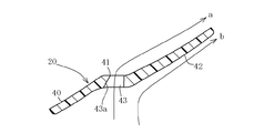
- the visor 20 is a transparent resin plate-like member, and bends from the inside to the outside to form an attachment portion 40, a step portion 41, and an air guide portion 42.
- the attachment portion 40 is attached by bolts 34 (FIG. 2) through the upper and lower through holes 40 a, 40 a along the surface of the upper extension portion 31, and outwardly and diagonally downward. It extends to.
- the step portion 41 is bent substantially horizontally in a valley fold toward the outside, and forms a flat surface directed forward.
- Reference numeral 41a denotes a bent portion line which forms a valley fold shape.
- two air guide holes 43 are provided vertically. However, the number of the air guide holes 43 may be one continuously, or may be three or more.
- the air guide hole 43 is open to the front and is formed so as to penetrate the front and back of the stepped portion 41.
- the inner wall surface 43a is an inclined surface with the rear side facing outward. Due to the wall surface 43a, the traveling wind that has entered the air guide hole 43 can be bent and flow outward as indicated by the arrow a in FIG.
- the air guide portion 42 extends outward in a diagonally downward rearward direction again from a bent portion 43b obtained by bending the outer side of the stepped portion 41 into a mountain fold shape.
- the tip of the air guide portion 42 reaches the vicinity of the knuckle guard 16 (see FIG. 2).
- the knuckle guard 16 in FIG. 5 simply represents the state at the foremost position at the time of maximum steering of the steering wheel.
- the tip of the air guide portion 42 is disposed so as not to interfere with the knuckle guard 16 at the forefront position.
- the step portion 41 is provided in a stepped shape, the position of the air guide portion 42 can be arranged further forward. Therefore, the visor 20 can be provided in front of the handle 12, without interfering with the handle 12, and the air guide portion 42 can be extended outward.
- the left visor 20 has a substantially quadrilateral shape, and a part of the upper side is reversely inclined. That is, if the four surrounding sides are an upper side 44, an inner side 45, a lower side 46, and an outer side 47, the upper side 44 and the lower side 46 are each formed in a substantially parallel right side (direction relative to the paper surface, hereinafter the same), and the inner side Similarly, 45 and the outer side 47 have a substantially parallel right-up shape.
- the upper side 44 is bent downward at the air guide portion 42.
- the upper side 48 in the air guide portion 42 is inclined backward to the right from the step portion 41. It is shaped as if a triangular portion 49 surrounded by an extension line of the upper side 44 and the outer side 47 indicated by a virtual line is cut out.
- the vertical width of the air guide portion 42 becomes narrower toward the outside.
- the height of the air guide portion 42 is H1 which is the highest on the stepped portion 41 side, H2 which is lower than H1 on the outer side 47 of the outer end portion, and the height becomes lower as going outward.
- the vertical width which is the width in the vertical direction, also changes so as to narrow toward the outside.
- the right visor is symmetrical with the left side.
- FIG. 7 illustrates traveling wind on the front and back of the air guide portion 42.
- the traveling wind toward the visor 20 is bent outward as indicated by an arrow b on the surface of the air guide portion 42 and travels toward the outer side 47 while being rectified to the surface.
- a part of the traveling wind enters the air guide hole 43 as indicated by an arrow “a” and exits behind the air guide portion 42.
- it is bent outward by the wall surface 43 a and flows in the direction of the outer side 47 along the back surface of the air guide portion 42. Therefore, the negative pressure generated on the back surface of the air guide portion 42 by the front-side traveling wind (arrow b) can be adjusted by the traveling air indicated by the arrow a formed on the back surface side of the air guiding portion 42.
- the entire structure of the front cowl 18 will be described with reference to FIGS.
- the visor 20 is shown in a separated state for the sake of explanation, and is attached to the front surface of the upward extending portion 31 as indicated by an arrow by post-processing.
- a headlight opening 36 into which the headlight 22 is fitted is provided at the center of the front cowl 18.
- the side of the headlight opening 36 forms a side portion 35 that is a rectifying surface that is continuous upward to the upper surface 32.
- the side portion 35 is formed with a substantially V-shaped groove in front view and extends in the front-rear direction.
- the rear end portion 35b of the side portion 35 is continuous to the rear edge 32b.
- An air duct 23 is opened at the front portion of the side portion 35.
- an upper deflector 24 is provided at the rear portion of the side portion 35 so as to cover the concave portion, and is opened on the rear end portion 35b.
- the upper deflector 24 is a rectifying surface, and is provided with an opening 24a directed forward. A part of the traveling wind flowing on the upper deflector 24 enters the inside of the upper deflector 24 through the opening 24a, and from the rear end portion 35b side. It comes out to the back.
- a lower portion 37 having a substantially portal shape in front view, and covers the radiator 50 (FIG. 1).
- the left and right side portions form a radiator shroud 38, which covers the side of the radiator 50 and has an air exhaust port 39 formed therein.
- the radiator shroud 38 is located in front of the rider's 51 knee 51d and lower knee 51e (FIG. 1).
- the rear edge is wide, and the lower deflector 25 is provided here.
- the side surface of the lower deflector 25 forms a rectifying surface arranged behind the lower side surface of the radiator shroud 38, and an opening 25b directed forward is formed through the front surface in the front-rear direction.
- the traveling wind that flows backward through the lower side surface of the radiator shroud 38 passes through the exhaust port 39 and flows on the outer surface of the lower deflector 25, and partly enters the opening 25 b, flows backward, and flows in the rear part of the lower deflector 25. Adjust the negative pressure.
- FIG. 1 a part of the traveling wind WD flowing to the front windshield device 19 is caused to flow upward by the screen 17 and to be spread left and right by the front cowl 18.
- the front windshield device 19 deflects the rider wind and the passenger 53 seated behind the rider 51 so that the traveling wind does not hit the upper body, thereby improving the windshield effect.
- a notch 33 is provided in front of the handle 12, and a part of the running wind hits the chest 51a and arms (especially under the elbow 51b) of the rider 51 through this part. Fatigue increases. In particular, at high speeds, the wind pressure increases and fatigue increases. However, since the visor 20 is provided so as to cover the notch 33, the traveling wind is bent on the outer side of the shoulder as indicated by the arrow A so as not to hit the rider 51 and the passenger 53. Be diverted to. For this reason, wind-up of the upper body, in particular, the chest 51a and the arm (particularly the lower elbow 51b) is improved, and fatigue during long-time running and high-speed running is reduced.
- air management is performed by adjusting the negative pressure formed on the back side of the visor 20 by flowing a running wind on the front and back of the visor 20.
- air management is performed by adjusting the negative pressure formed on the back side of the visor 20 by flowing a running wind on the front and back of the visor 20.
- the large notch 33 remains as it is, a large steering angle can be maintained as it is. Therefore, it is suitable for a vehicle having a large steering angle, particularly for an off-road vehicle.
- the knuckle guard 16 is suitable for a vehicle provided with the knuckle guard 16, and the knuckle guard 16 is provided and the turning angle is large. It is most suitable for road vehicles.
- the upper deflector 24 causes the running wind at the intermediate portion in the vertical direction to be deflected to the outside of the belly (especially the flank) 51c as shown by the arrow B, so Windproof performance is improved.
- air management that adjusts the negative pressure formed on the back surface side of the upper deflector 24 by flowing the running air in and out of the upper deflector 24 can contribute to improving the running performance.
- the lower deflector 25 deflects the traveling wind at the lower part in the vertical direction outward as shown by the arrow C to the outside of the knee 51d, so that the windproof performance of the knee 51d and the knee lower part 51e is improved.
- the traveling wind flows inside and outside the lower deflector 25, the negative pressure formed on the back side of the lower deflector 25 is adjusted to perform air management, which can contribute to an improvement in traveling performance particularly during high speed traveling. .
- air management is performed on the screen 17 through the opening 26, and air management is performed on the upper extending portion 31 through the gap 28 and the upper extending portion 31. Further, by arranging the winker 21 so as to overlap the front side of the knuckle guard 16, the traveling wind hitting the knuckle guard 16 is dispersed to reduce the wind pressure on the knuckle guard 16.
- this invention is not limited to the said embodiment, A various application and deformation
- the upper extension 31 may not be provided on the front cowl 18, but instead the lower portion of the screen 17 may be expanded to the left and right, and the left and right portions may be cut away to provide a handle escape recess.
- FIG. 8 shows this, and is another embodiment of the portion corresponding to FIG.
- symbol is used for a common part with previous embodiment.
- the notch portion 30 of the previous embodiment is not formed, the lower left and right sides of the screen 17A form an extended portion 60 corresponding to the upward extending portion 31, and the side portion thereof extends to the rear edge 32b.
- a cutout portion 61 is formed so as to be continuous. The cutout portion 61 is continuous with the rear edge 32b, and is a relief portion for steering the steering wheel like the cutout portion 33 of the previous embodiment.
- the gap 28 is formed as a hole 62 penetrating the front and back of the screen 17 ⁇ / b> A between the expanded portion 60 and the opening 26.
- the visor 20 is provided in front of the extension 60 as in the previous embodiment. Even in this case, it is possible to improve the windproof performance of the rider 51 on the chest 51a and the lower elbow 51b (see FIG. 1) while providing the notch 61 of the screen 17A and ensuring a large steering angle. .
- the notch portions (33, 61) forming the handle escape portion for steering the steering wheel may be provided on either or both of the front cowl 18 and the screen 17, and in this sense, to the front windshield device 19. It can be set as the structure which provided the notch part 33. FIG.
- the subject saddle-riding type vehicle is not limited to an off-road system and can be applied to various uses.
- the knuckle guard 16 may not be provided.
- not only two-wheeled vehicles but also three-wheeled or four-wheeled vehicles may be used.
- the handle 12 is a bar handle, it does not necessarily have to be an up handle.
- the front windshield device is provided. Useful for saddle-ride type vehicles.
Landscapes
- Engineering & Computer Science (AREA)
- Mechanical Engineering (AREA)
- Steering Devices For Bicycles And Motorcycles (AREA)
- Body Structure For Vehicles (AREA)
- Lighting Device Outwards From Vehicle And Optical Signal (AREA)
Abstract
[Problem] Forming a large clearance ahead, that is, in front of the handlebar and the front fairing, in order to secure a large turning angle causes laminar airflow passing through the clearance to hit the rider in the chest and the like; therefore, the laminar airflow is to be prevented from hitting the rider in the chest and the like even as a large turning angle is retained. [Solution] A large notch part 33 is formed in the upper portion of a front fairing 18 in front of the upright part 12a of an upright handlebar 12 in order to provide the handlebar 12 with turning range. An upwardly-projecting part 31 narrowed by the notch portion 33 is formed. A visor 20 is attached to the front of the upwardly-projecting part 31 so as to cover the notch part 33, deflecting the laminar airflow moving toward the notch portion 33 to the outside and away from a rider 51.
Description
この発明は、大きいハンドル転舵角を保持しながらもライダーの上半身に対する防風性能を向上させたフロントカウルを有する鞍乗り型車両に関する。
The present invention relates to a saddle-ride type vehicle having a front cowl in which a windproof performance for a rider's upper body is improved while maintaining a large steering angle.
The present invention relates to a saddle-ride type vehicle having a front cowl in which a windproof performance for a rider's upper body is improved while maintaining a large steering angle.
鞍乗り型車両の前部にフロントカウルを設けて、ライダーの上半身等に対する防風をするとともに、フロントカウルのハンドル前方部を切り欠いて、ハンドル逃げ用の切り欠き部を設け、大きいハンドル転舵角を確保したものがある(特許文献1参照)。
A front cowl is installed at the front of the saddle-ride type vehicle to prevent wind from the rider's upper body, etc., and the front part of the front cowl handle is notched to provide a notch for escape of the handle, resulting in a large steering angle (See Patent Document 1).
A front cowl is installed at the front of the saddle-ride type vehicle to prevent wind from the rider's upper body, etc., and the front part of the front cowl handle is notched to provide a notch for escape of the handle, resulting in a large steering angle (See Patent Document 1).
上記従来例のように、フロントカウルにハンドル逃げ用の切り欠き部を設けると、この切り欠き部を通過した走行風がライダーの上半身、特に胸や肩に当たるため、この風圧が走行時の疲労を増大させる一因になる。特に、高速走行になるほどライダーへの風圧が増加する。
一方、ハンドル逃げ用の切り欠き部は、大きいハンドル転舵角を保持する上で必要になる。しかも、ハンドル転舵角を大きくすればするほど、ハンドル逃げ用の切り欠き部は大きくならざるをえない。
このような大きいハンドル転舵角を必要とする車種は用途によって存在し、特にオフロード系車種に多くなる。また、ハンドルの一部を上方へ曲げてグリップ位置を高くしたアップハンドルを採用すると、ハンドル逃げ用の切り欠き部がライダーの胸前方となる高い位置になる。また、ハンドルのグリップ前方にナックルガードを設けた車種では、さらに大きな切り欠き部が必要になった。
しかし、ハンドル逃げ用の切り欠き部が大きくなればなるほど、ライダーに当たる走行風の風圧も高くなってしまう。
そこで、本願発明は、フロントカウルについて、大きいハンドル転舵角を保持しながらもライダーの上半身に対する防風性能を向上させることを目的とする。
If the front cowl has a notch for escaping the handle as in the previous example, the wind that passes through the notch hits the rider's upper body, especially the chest and shoulders. It contributes to increase. In particular, the wind pressure on the rider increases at higher speeds.
On the other hand, a notch for escaping the steering wheel is necessary for maintaining a large steering angle. In addition, the larger the steering wheel turning angle, the larger the notch for escaping the steering wheel.
Vehicle types that require such a large steering wheel turning angle exist depending on the application, and particularly increase in off-road vehicle types. In addition, when an up handle in which a part of the handle is bent upward and the grip position is increased is adopted, the cutout portion for escaping the handle becomes a high position at the front of the rider's chest. In addition, a car with a knuckle guard in front of the handlebar grip requires a larger notch.
However, the larger the notch for escaping the steering wheel, the higher the wind pressure of the running wind hitting the rider.
Accordingly, the present invention has an object to improve the windproof performance of the front cowl against the upper body of the rider while maintaining a large steering angle.
上記課題を解決するため本願発明の鞍乗り型車両に係る第1の発明は、前輪懸架装置(10)と、この前輪懸架装置を操舵するハンドル(12)と、これら前輪懸架装置の上部及び前記ハンドルを車両前方から覆うフロントカウル(18)と、このフロントカウルの上方に配置されるスクリーン(17)とを有する前部風防装置(19)を備えた鞍乗り型車両において、
前記前部風防装置(19)に、前記ハンドル前方部を切り欠いて設けたハンドル逃げ用の切り欠き部(33)と、
この切り欠き部(33)により幅狭にされ、かつ前記切り欠き部(33)の内側を前記ハンドル(12)の高さから上方へ延びる幅狭部(31)と、
この幅狭部(31)から外側方へ延出して、前記切り欠き部(33)及び前記ハンドル(12)前方を覆うバイザー(20)を設けるとともに、
このバイザー(20)を前記幅狭部(31)の前方に設けたことを特徴とする。
このようにすると、転舵時のハンドル(12)と干渉しないバイザー(20)が、切り欠き部(33)の前方を覆う。また、バイザー(20)は外側方へ延出している。したがって、切り欠き部(33)へ向かう走行風は、バイザー(20)により外側方へ流される。 In order to solve the above problems, a first invention related to a saddle-ride type vehicle according to the present invention includes a front wheel suspension device (10), a handle (12) for steering the front wheel suspension device, an upper portion of the front wheel suspension device, In a saddle-ride type vehicle including a front windshield device (19) having a front cowl (18) that covers a steering wheel from the front of the vehicle and a screen (17) disposed above the front cowl,
A notch part (33) for escaping the handle provided in the front windshield device (19) by notching the front part of the handle;
A narrow portion (31) which is narrowed by the notch (33) and extends upward from the height of the handle (12) inside the notch (33);
A visor (20) that extends outward from the narrow portion (31) and covers the front of the notch (33) and the handle (12) is provided.
The visor (20) is provided in front of the narrow portion (31).
If it does in this way, the visor (20) which does not interfere with the steering wheel (12) at the time of steering will cover the front part of a notch part (33). The visor (20) extends outward. Accordingly, the traveling wind toward the notch (33) is caused to flow outward by the visor (20).
第2の発明は、前記バイザー(20)は、その内側端部を前記幅狭部に取り付けられた取付部(40)とし、この取付部から屈曲して外側方へ延びる段差部(41)と、この段差部から後方へ曲げられてさらに外側方へ延び表面が導風面となる導風部(42)を備えることを特徴とする。
これにより、バイザー(20)をハンドル(12)の前方へハンドル(12)と干渉せずに、外側方へ長く延出させて設けることができる。 According to a second aspect of the present invention, the visor (20) has an inner end portion as an attachment portion (40) attached to the narrow portion, and a step portion (41) which is bent from the attachment portion and extends outward. Further, the step is provided with a wind guide portion (42) which is bent backward from the stepped portion and extends further outward, and has a surface serving as a wind guide surface.
Accordingly, the visor (20) can be provided to extend outwardly long without interfering with the handle (12) in front of the handle (12).
第3の発明は、前記バイザー(20)の前記段差部(41)に導風孔(43)を設けたことを特徴とする。
これにより、走行風の一部を、導風孔(43)から導風部(42)の背面側へ流すことができる。このため、導風部(42)の表面を流れる走行風により導風部(42)の背面側に生じる負圧を、導風部(42)の背面側に流れる走行風で調整できる。 The third invention is characterized in that an air guide hole (43) is provided in the step portion (41) of the visor (20).
Thereby, a part of driving | running | working wind can be flowed to the back side of a baffle part (42) from a baffle hole (43). For this reason, the negative pressure produced on the back side of the wind guide part (42) by the running wind flowing on the surface of the wind guide part (42) can be adjusted by the running wind flowing on the back side of the wind guide part (42).
第4の発明は、前記バイザー(20)の導風部(42)は、その外側端部が外側に行くほど高さ方向の長さが短くなることを特徴とする。
このようにすると、導風部(42)の外側端部における風圧を下げることができるので、導風部(42)の外側端部に生じるビビリ音を低減できる。 The fourth invention is characterized in that the air guide portion (42) of the visor (20) has a shorter length in the height direction as its outer end portion goes outward.
If it does in this way, since the wind pressure in the outer side edge part of a wind guide part (42) can be lowered | hung, the chatter sound which arises in the outer side edge part of a wind guide part (42) can be reduced.
第5の発明は、前記ハンドル(12)は、その両端にナックルガード(16)を備えていることを特徴とする。
このようにすると、バイザー(20)が幅狭部(31)の前方に位置するため、ナックルガード(16)をバイザー(20)と干渉せずに設けることができる。しかも、ハンドルの転舵角に影響を与えることなく設けることができる。
The fifth invention is characterized in that the handle (12) includes knuckle guards (16) at both ends thereof.
If it does in this way, since a visor (20) is located ahead of a narrow part (31), a knuckle guard (16) can be provided without interfering with a visor (20). Moreover, it can be provided without affecting the steering angle of the steering wheel.
転舵するハンドルを逃げる切り欠き部の前方を覆い、外側方へ延出するバイザーを、前部風防装置の切り欠き部によって形成された幅狭部の前方に設けたので、切り欠き部へ向かう走行風をバイザーにより外側方へ流し、ライダーへ当たらないようにすることができる。また、バイザーは幅狭部の前方に設けられるので、転舵時のハンドルと干渉しない。
したがって、大きいハンドル転舵角を保持しながらもライダーの上半身に対する防風性能を向上させることができる。
その結果、走行時の疲労を低減でき、長時間走行するロングツーリングや高速走行時の疲労を低減できる。
A visor that covers the front of the notch that escapes the steering wheel and extends outward is provided in front of the narrow part formed by the notch of the front windshield device, so it heads toward the notch. The running wind can be swept outward by the visor so that it does not hit the rider. Further, since the visor is provided in front of the narrow portion, it does not interfere with the steering wheel during turning.
Therefore, it is possible to improve the windproof performance for the upper body of the rider while maintaining a large steering angle.
As a result, fatigue during traveling can be reduced, and long tooling that travels for a long time and fatigue during high-speed traveling can be reduced.
以下、一実施の形態を説明する。
図1は鞍乗り型車両の斜視図、図2はこの鞍乗り型車両における前部の正面図、図3、図4は前部風防装置の斜視図及び正面図、図5は車体取付状態にあるバイザーの上方視図、図6はバイザーの正面図、図7は図6の7-7線に沿う断面図である。 Hereinafter, an embodiment will be described.
1 is a perspective view of the saddle-ride type vehicle, FIG. 2 is a front view of the front portion of the saddle-ride type vehicle, FIGS. 3 and 4 are perspective views and front views of the front windshield device, and FIG. FIG. 6 is a front view of a visor, FIG. 7 is a cross-sectional view taken along line 7-7 in FIG.
図1において、この鞍乗り型車両は2人乗り用のオフロードバイクであり、車体フレーム(図示せず)の前部に回動可能に支持されたフロントフォーク10(前輪懸架装置)と、このフロントフォーク10の下部に支持された前輪11と、フロントフォーク10の上部に取付けられた操舵用のハンドル12と、ハンドル12の後方に配置された2人用シート13と、その下方に位置し、車体フレームに支持される後輪14と、前輪11と後輪14の間に位置して車体フレームに支持されるエンジン15を備える。
In FIG. 1, this saddle-ride type vehicle is a two-seater off-road motorcycle, which includes a front fork 10 (front wheel suspension device) rotatably supported on a front portion of a body frame (not shown), A front wheel 11 supported at the lower part of the front fork 10; a steering handle 12 attached to the upper part of the front fork 10; a seat for two persons 13 arranged behind the handle 12; A rear wheel 14 supported by the body frame and an engine 15 positioned between the front wheel 11 and the rear wheel 14 and supported by the body frame are provided.
ハンドル12はバーハンドルであり、一部を折り曲げて長さ方向両端のハンドルグリップ12b(図2)を高くしたアップハンドルである。ハンドルグリップ12bの前方をナックルガード16で覆われている。ナックルガード16はハンドルを握る手を保護するとともに、ハンドルグリップ12bに対する風圧を下げる防風部材として機能する。
The handle 12 is a bar handle, and is an up handle in which a handle grip 12b (FIG. 2) at both ends in the longitudinal direction is raised by bending a part thereof. The front side of the handle grip 12b is covered with a knuckle guard 16. The knuckle guard 16 functions as a windproof member that protects the hand holding the handle and lowers the wind pressure on the handle grip 12b.
ハンドル12の前方は、スクリーン17と、フロントカウル18とからなる前部風防装置19で覆われている。前部風防装置19は、乗員(ライダー51、同乗者53)へ向かう走行風を曲げて、乗員から逸らすものである。
なお、図1において、51fはライダー51の足であり、フットレスト52上に支持される。54は同乗者53のピリオンステップである。 The front of the handle 12 is covered with afront windshield device 19 including a screen 17 and a front cowl 18. The front windshield device 19 bends the traveling wind toward the occupant (rider 51, passenger 53) and deflects it from the occupant.
In FIG. 1, 51 f is a leg of therider 51 and is supported on the footrest 52. 54 is a pillion step of the passenger 53.
なお、図1において、51fはライダー51の足であり、フットレスト52上に支持される。54は同乗者53のピリオンステップである。 The front of the handle 12 is covered with a
In FIG. 1, 51 f is a leg of the
スクリーン17の上部かつハンドル12の前方となる位置には、板状の透明な樹脂からなるバイザー20が設けられている。バイザー20は導風部材の一つである。
バイザー20の近傍にはウインカ21が車幅方向へ長く設けられ、正面視でナックルガード16に重なり、ナックルガード16へ向かう走行風を分散させるようになっている。
スクリーン17の下方かつフロントカウル18の前方へ突出する前端部には、左右一対のヘッドライト22が設けられている。 Avisor 20 made of a plate-like transparent resin is provided at a position above the screen 17 and in front of the handle 12. The visor 20 is one of the air guide members.
Ablinker 21 is provided in the vicinity of the visor 20 in the vehicle width direction so as to overlap the knuckle guard 16 in a front view and disperse the traveling wind toward the knuckle guard 16.
A pair of left andright headlights 22 are provided at the front end portion that projects below the screen 17 and forward of the front cowl 18.
バイザー20の近傍にはウインカ21が車幅方向へ長く設けられ、正面視でナックルガード16に重なり、ナックルガード16へ向かう走行風を分散させるようになっている。
スクリーン17の下方かつフロントカウル18の前方へ突出する前端部には、左右一対のヘッドライト22が設けられている。 A
A
A pair of left and
フロントカウル18のうち、ヘッドライト22の側方左右にはエアダクト23が設けられ、図示しないエアクリーナへ走行風を取り込んでいる。
エアダクト23より上方となるフロントカウル18の側方で、ウインカ21の近傍下方にアッパーデフレクタ24が設けられている。フロントカウル18の側方下部でライダーの膝前方には、ロアデフレクタ25が設けられている。 Of thefront cowl 18, air ducts 23 are provided on the left and right sides of the headlight 22, and the running wind is taken into an air cleaner (not shown).
Anupper deflector 24 is provided on the side of the front cowl 18 above the air duct 23 and in the vicinity below the turn signal 21. A lower deflector 25 is provided in a lower side portion of the front cowl 18 and in front of the rider's knee.
エアダクト23より上方となるフロントカウル18の側方で、ウインカ21の近傍下方にアッパーデフレクタ24が設けられている。フロントカウル18の側方下部でライダーの膝前方には、ロアデフレクタ25が設けられている。 Of the
An
アッパーデフレクタ24、ロアデフレクタ25はエアマネジメント装置であり、高速走行時における走行安定性の向上に貢献している。
なお、スクリーン17の下部中央に設けられている開口26及びスクリーン17とバイザー20近傍に形成されている間隙28並びにバイザー20も、エアマネジメントをなしている。 Theupper deflector 24 and the lower deflector 25 are air management devices, which contribute to improving running stability during high speed running.
The opening 26 provided in the lower center of thescreen 17, the gap 28 formed in the vicinity of the screen 17 and the visor 20, and the visor 20 also form air management.
なお、スクリーン17の下部中央に設けられている開口26及びスクリーン17とバイザー20近傍に形成されている間隙28並びにバイザー20も、エアマネジメントをなしている。 The
The opening 26 provided in the lower center of the
バイザー20、ウインカ21、エアダクト23、アッパーデフレクタ24、ロアデフレクタ25、間隙28は、それぞれ車両の左右に一対で設けられている。
The visor 20, the blinker 21, the air duct 23, the upper deflector 24, the lower deflector 25, and the gap 28 are provided in pairs on the left and right sides of the vehicle.
図2は、車両前部のうち、バイザー20近傍部を主体とする上部側部分の正面図である。この図を中心に図3~図5により、前部風防装置19の上部構造について以下説明する。スクリーン17は透明な樹脂製であり、縦長形状をなし、フロントカウル18の上部へ後傾して取付けられている。
FIG. 2 is a front view of an upper side portion mainly composed of the vicinity of the visor 20 in the front portion of the vehicle. The upper structure of the front windshield device 19 will be described below with reference to FIGS. The screen 17 is made of a transparent resin, has a vertically long shape, and is attached to the upper portion of the front cowl 18 by tilting backward.
スクリーン17の表面は前方へ凸の3次元曲面からなる整流面をなし、上下側は斜め上がり後方へ向かい、かつ左右側は後方へ向かって斜め外側方へ広がる曲面となっている。
The surface of the screen 17 forms a rectifying surface made up of a three-dimensional curved surface that protrudes forward, and the upper and lower sides are inclined upward and toward the rear, and the left and right sides are curved surfaces that extend obliquely outward toward the rear.
スクリーン17の下部は、左右に切り欠き部30が設けられ、幅狭になっている。この幅狭部分の中央に開口26が形成されている。開口26の後方には、開口26の後方を覆うようにガイド部材27が後傾して配置されている。ガイド部材27は板状をなして下部をフロントカウル18の上部に取付けられ、上部はスクリーン17から後方へ離隔して開口26から入った走行風をスクリーン17の背面にて上方へ流すようになっている。
スクリーン17の表面に沿って上方へ流れる走行風によってスクリーン17の背面側に生じる負圧は、開口26から入ってスクリーン17の背面を流れる走行風により調整される。 The lower part of thescreen 17 is provided with notches 30 on the left and right sides, and is narrow. An opening 26 is formed in the center of the narrow portion. A guide member 27 is disposed behind the opening 26 so as to incline backward so as to cover the rear of the opening 26. The guide member 27 has a plate shape, and the lower part is attached to the upper part of the front cowl 18. The upper part is separated from the screen 17 in the rearward direction so that the traveling wind entering from the opening 26 flows upward on the rear surface of the screen 17. ing.
The negative pressure generated on the back side of thescreen 17 by the traveling wind that flows upward along the surface of the screen 17 is adjusted by the traveling wind that enters the opening 26 and flows on the back surface of the screen 17.
スクリーン17の表面に沿って上方へ流れる走行風によってスクリーン17の背面側に生じる負圧は、開口26から入ってスクリーン17の背面を流れる走行風により調整される。 The lower part of the
The negative pressure generated on the back side of the
切り欠き部30は、車体中央側(中心線CL側)へ食い込むように湾曲した曲線でスクリーン17の下部左右に形成されている。
切り欠き部30の外側方には、上方延出部31がフロントカウル18の上部から上方へ突出して一体に設けられている。上方延出部31もスクリーンの左右に一対で設けられている。上方延出部31は本願発明の幅狭部になっている。 Thecutout portions 30 are formed on the left and right sides of the screen 17 with curved curves so as to bite into the vehicle body center side (center line CL side).
On the outer side of thecutout portion 30, an upward extending portion 31 is integrally provided so as to protrude upward from the upper portion of the front cowl 18. A pair of upper extending portions 31 are also provided on the left and right sides of the screen. The upward extending portion 31 is a narrow portion of the present invention.
切り欠き部30の外側方には、上方延出部31がフロントカウル18の上部から上方へ突出して一体に設けられている。上方延出部31もスクリーンの左右に一対で設けられている。上方延出部31は本願発明の幅狭部になっている。 The
On the outer side of the
上方延出部31は、切り欠き部30によるスクリーン17の外側方の空間へ入り込むように配置され、スクリーン17との間に間隙28を形成している。上方延出部31の表面は、前方かつ斜め外方を指向する整流面をなしている。
上方延出部31は、前後方向へ長く配置され、前縁31aはスクリーン17の表面と同程度に位置し、切り欠き部30との間で間隙28を形成している。
上方延出部31の後縁31bは、前縁31aよりも外方に位置する。 The upward extendingportion 31 is disposed so as to enter the space outside the screen 17 by the notch portion 30, and forms a gap 28 between the screen 17. The surface of the upper extension 31 forms a rectifying surface that is directed forward and obliquely outward.
Theupper extension portion 31 is disposed long in the front-rear direction, the front edge 31 a is located at the same level as the surface of the screen 17, and forms a gap 28 with the notch portion 30.
Therear edge 31b of the upward extending portion 31 is located outward from the front edge 31a.
上方延出部31は、前後方向へ長く配置され、前縁31aはスクリーン17の表面と同程度に位置し、切り欠き部30との間で間隙28を形成している。
上方延出部31の後縁31bは、前縁31aよりも外方に位置する。 The upward extending
The
The
間隙28には、スクリーン17の下部表面から外側方へ曲げられて後方へ流れる走行風が入り、上方延出部31の背面側を外側方へ流れる。
一方、上方延出部31の表面は、前方から及びスクリーン17から流れてきた走行風を外側方へ流す。この上方延出部31の表面を流れる走行風によって上方延出部31の背面側に生じる負圧は、間隙28から上方延出部31の背面を流れる走行風により調整される。 A running wind that is bent outward from the lower surface of thescreen 17 and flows backward enters the gap 28 and flows outward on the back side of the upper extension 31.
On the other hand, the surface of theupper extension part 31 allows the traveling wind flowing from the front and from the screen 17 to flow outward. The negative pressure generated on the back side of the upper extension portion 31 by the running wind flowing on the surface of the upper extension portion 31 is adjusted by the running wind flowing from the gap 28 to the back surface of the upper extension portion 31.
一方、上方延出部31の表面は、前方から及びスクリーン17から流れてきた走行風を外側方へ流す。この上方延出部31の表面を流れる走行風によって上方延出部31の背面側に生じる負圧は、間隙28から上方延出部31の背面を流れる走行風により調整される。 A running wind that is bent outward from the lower surface of the
On the other hand, the surface of the
上方延出部31は、フロントカウル18の上面32に連続している。上面32は、スクリーン17の下方かつヘッドライト22の上方を覆う整流面であり、後方へ斜め上がり、かつ外側方へ斜め上がりに延びる3次元曲面をなしている。
The upward extending portion 31 is continuous with the upper surface 32 of the front cowl 18. The upper surface 32 is a rectifying surface that covers the lower side of the screen 17 and the upper side of the headlight 22, and has a three-dimensional curved surface extending obliquely rearward and obliquely upward outward.
上面32の後縁32bは、後縁31bと連続するが、この連続部はハンドル転舵時におけるハンドル逃げ用の切り欠き部33となっている。
ハンドル12は長さ方向中間部で上方へ屈曲して高くなった後、再び略水平に外方へ延びる屈曲形状をなし、長さ方向中間部で上方へ屈曲して高くなった部分がアップ部12aをなし、その長さ方向端部にハンドルグリップ部12bが設けられている。 Therear edge 32b of the upper surface 32 is continuous with the rear edge 31b, and this continuous part is a notch part 33 for escaping the steering wheel when steering the steering wheel.
The handle 12 bends upward at the middle in the length direction and then becomes higher, and then forms a bent shape that extends outwards substantially horizontally again, and the portion bent and raised at the middle in the length direction is the up portion. 12a is formed, and ahandle grip portion 12b is provided at the end in the length direction.
ハンドル12は長さ方向中間部で上方へ屈曲して高くなった後、再び略水平に外方へ延びる屈曲形状をなし、長さ方向中間部で上方へ屈曲して高くなった部分がアップ部12aをなし、その長さ方向端部にハンドルグリップ部12bが設けられている。 The
The handle 12 bends upward at the middle in the length direction and then becomes higher, and then forms a bent shape that extends outwards substantially horizontally again, and the portion bent and raised at the middle in the length direction is the up portion. 12a is formed, and a
切り欠き部33は、ハンドル12の大きい転舵角を確保するため、ハンドル12のアップ部12aの回動範囲と干渉しないように、上方延出部31の後部及びフロントカウル18の後部を一部切り欠いて設けられる。この切り欠き部33を設けた結果、上方延出部31は横幅(左右方向の幅)が狭い幅狭にされ、かつ切り欠き部33の内側を上方へ延びている幅狭部でもある。
この幅狭部分はほぼ上方延出部31全体であり、ハンドル12のアップ部12a前方かつアップ部12aの高さ位置からより上方部分である。 Thenotch 33 partially secures the rear part of the upper extension part 31 and the rear part of the front cowl 18 so as not to interfere with the rotation range of the up part 12a of the handle 12 in order to ensure a large turning angle of the handle 12. Cut out and provided. As a result of the provision of the notch 33, the upward extending portion 31 is a narrow portion having a narrow lateral width (width in the left-right direction) and extending upward inside the notch 33.
This narrow portion is substantially the entire upwardly extendingportion 31, and is an upper portion in front of the up portion 12 a of the handle 12 and from the height position of the up portion 12 a.
この幅狭部分はほぼ上方延出部31全体であり、ハンドル12のアップ部12a前方かつアップ部12aの高さ位置からより上方部分である。 The
This narrow portion is substantially the entire upwardly extending
上方延出部31の下部前面には、バイザー20が切り欠き部33の前方を覆うようにボルト34等の固定具で着脱自在に取付けられている。バイザー20は、上方延出部31から外側方へ向かって斜め後方へ延出する整流面である。また、転舵時におけるハンドル12のアップ部12a及びナックルガード16と干渉しないよう、これらの前方に所定間隔をもって配置される。さらに、バイザー20の上方延出部31に対する取付部寄り位置には、前方へ指向して開口する導風孔43が形成されている。
The visor 20 is detachably attached to the lower front surface of the upper extension portion 31 with a fixture such as a bolt 34 so as to cover the front of the notch portion 33. The visor 20 is a rectifying surface that extends obliquely rearward from the upper extending portion 31 toward the outer side. Moreover, it arrange | positions with these at the front of these so that it may not interfere with the up part 12a and the knuckle guard 16 of the steering wheel 12 at the time of steering. Furthermore, an air guide hole 43 that opens toward the front is formed at a position closer to the attachment portion of the visor 20 with respect to the upward extension portion 31.
次に、バイザー20の詳細について、図5~図7を中心に説明する。
バイザー20は透明な樹脂製の板状部材であり、内側から外側へ向かって曲がり、取付部40、段差部41、導風部42となっている。
図5に示すように、取付部40は上方延出部31の表面に沿って、上下に設けられた通し穴40a、40aにより、ボルト34(図2)で取付けられ、後方斜め下がりに外側方へ延びている。 Next, details of thevisor 20 will be described with reference to FIGS.
Thevisor 20 is a transparent resin plate-like member, and bends from the inside to the outside to form an attachment portion 40, a step portion 41, and an air guide portion 42.
As shown in FIG. 5, theattachment portion 40 is attached by bolts 34 (FIG. 2) through the upper and lower through holes 40 a, 40 a along the surface of the upper extension portion 31, and outwardly and diagonally downward. It extends to.
バイザー20は透明な樹脂製の板状部材であり、内側から外側へ向かって曲がり、取付部40、段差部41、導風部42となっている。
図5に示すように、取付部40は上方延出部31の表面に沿って、上下に設けられた通し穴40a、40aにより、ボルト34(図2)で取付けられ、後方斜め下がりに外側方へ延びている。 Next, details of the
The
As shown in FIG. 5, the
段差部41は外側方へ向けて谷折り状に略水平に屈曲し、前方を指向する平面をなす。41aは谷折り状をなす屈曲部の線である。ここに導風孔43が上下に2個設けられている。但し、導風孔43は、上下を連続して一つにしてもよく、逆に3個以上の多数にしてもよい。
The step portion 41 is bent substantially horizontally in a valley fold toward the outside, and forms a flat surface directed forward. Reference numeral 41a denotes a bent portion line which forms a valley fold shape. Here, two air guide holes 43 are provided vertically. However, the number of the air guide holes 43 may be one continuously, or may be three or more.
導風孔43は前方を指向して開口し、段差部41の表裏に貫通して形成される。また、導風孔43を囲む壁面のうち、内側の壁面43aは後方が外側方になる傾斜面になっている。壁面43aにより、図7の矢示aのように導風孔43へ入った走行風を外側方へ曲げて流すことができる。
The air guide hole 43 is open to the front and is formed so as to penetrate the front and back of the stepped portion 41. Of the wall surfaces surrounding the air guide hole 43, the inner wall surface 43a is an inclined surface with the rear side facing outward. Due to the wall surface 43a, the traveling wind that has entered the air guide hole 43 can be bent and flow outward as indicated by the arrow a in FIG.
導風部42は、段差部41の外側方を山折り状に屈曲させた曲げ部43bから再び後方斜め下がりに外側方へ延出している。導風部42の先端は、ナックルガード16近傍まで達している(図2参照)。
The air guide portion 42 extends outward in a diagonally downward rearward direction again from a bent portion 43b obtained by bending the outer side of the stepped portion 41 into a mountain fold shape. The tip of the air guide portion 42 reaches the vicinity of the knuckle guard 16 (see FIG. 2).
図5におけるナックルガード16は、ハンドルの最大転舵時における最前方位置にある状態を簡略的に表現している。このように、導風部42の先端は、最前方位置のナックルガード16と干渉しないように配置されている。
特に、段差部41で段差状をなして設けられるので、導風部42の位置をより前方へ配置できる。このため、バイザー20をハンドル12の前方へ、ハンドル12と干渉せずに、かつ導風部42を外側方へ長く延出させて設けることができる。 Theknuckle guard 16 in FIG. 5 simply represents the state at the foremost position at the time of maximum steering of the steering wheel. In this way, the tip of the air guide portion 42 is disposed so as not to interfere with the knuckle guard 16 at the forefront position.
In particular, since thestep portion 41 is provided in a stepped shape, the position of the air guide portion 42 can be arranged further forward. Therefore, the visor 20 can be provided in front of the handle 12, without interfering with the handle 12, and the air guide portion 42 can be extended outward.
特に、段差部41で段差状をなして設けられるので、導風部42の位置をより前方へ配置できる。このため、バイザー20をハンドル12の前方へ、ハンドル12と干渉せずに、かつ導風部42を外側方へ長く延出させて設けることができる。 The
In particular, since the
図6に示すように、左側のバイザー20は略4辺形形状をなし、上辺の一部を逆傾斜させた形状になっている。すなわち、周囲の4辺を上辺44、内側辺45、下辺46、外側辺47とすれば、上辺44及び下辺46はそれぞれ略平行な右(紙面に対する方向、以下同)上がり状をなし、内側辺45及び外側辺47も同様にそれぞれ略平行な右上がり状をなしている。
As shown in FIG. 6, the left visor 20 has a substantially quadrilateral shape, and a part of the upper side is reversely inclined. That is, if the four surrounding sides are an upper side 44, an inner side 45, a lower side 46, and an outer side 47, the upper side 44 and the lower side 46 are each formed in a substantially parallel right side (direction relative to the paper surface, hereinafter the same), and the inner side Similarly, 45 and the outer side 47 have a substantially parallel right-up shape.
しかし、上辺44は、導風部42で下方へ曲がっている。すなわち導風部42における上辺48は、段差部41より右下がりに逆傾斜している。あたかも、仮想線で示す上辺44と外側辺47の延長線で囲まれた3角形部分49を切り取ったような形状をなしている。
However, the upper side 44 is bent downward at the air guide portion 42. In other words, the upper side 48 in the air guide portion 42 is inclined backward to the right from the step portion 41. It is shaped as if a triangular portion 49 surrounded by an extension line of the upper side 44 and the outer side 47 indicated by a virtual line is cut out.
その結果、導風部42の上下幅は、外方ほど狭くなる。したがって、導風部42の高さは、段差部41側が最も高いH1であり、外端部の外側辺47ではH1より低いH2となり、外方へ行くほど高さが低くなるようになっている。すなわち、上下方向の幅である縦幅も外側方へ向かって狭くなるように変化している。
これにより、外端側の風圧を下げてビビリ音を生じにくくすることができる。
なお、右側のバイザーは左側と対称形状になっている。 As a result, the vertical width of theair guide portion 42 becomes narrower toward the outside. Accordingly, the height of the air guide portion 42 is H1 which is the highest on the stepped portion 41 side, H2 which is lower than H1 on the outer side 47 of the outer end portion, and the height becomes lower as going outward. . That is, the vertical width, which is the width in the vertical direction, also changes so as to narrow toward the outside.
Thereby, the wind pressure on the outer end side can be lowered to make it difficult to generate chatter noise.
The right visor is symmetrical with the left side.
これにより、外端側の風圧を下げてビビリ音を生じにくくすることができる。
なお、右側のバイザーは左側と対称形状になっている。 As a result, the vertical width of the
Thereby, the wind pressure on the outer end side can be lowered to make it difficult to generate chatter noise.
The right visor is symmetrical with the left side.
図7は、導風部42の表裏における走行風を説明する。バイザー20に向かう走行風は、導風部42の表面にて、矢示bのように外側方へ曲げられ、表面に整流されながら外側辺47方向へ向かう。
一方、走行風の一部は、矢示aのように導風孔43内へ入り、導風部42の後方へ抜ける。このとき、壁面43aにより外側方へ曲げられて、導風部42の背面に沿って外側辺47方向へ流れる。
したがって、表面側の走行風(矢示b)によって導風部42の背面に生じる負圧は、導風部42の背面側に形成される矢示aの走行風によって調整することができる。 FIG. 7 illustrates traveling wind on the front and back of theair guide portion 42. The traveling wind toward the visor 20 is bent outward as indicated by an arrow b on the surface of the air guide portion 42 and travels toward the outer side 47 while being rectified to the surface.
On the other hand, a part of the traveling wind enters theair guide hole 43 as indicated by an arrow “a” and exits behind the air guide portion 42. At this time, it is bent outward by the wall surface 43 a and flows in the direction of the outer side 47 along the back surface of the air guide portion 42.
Therefore, the negative pressure generated on the back surface of theair guide portion 42 by the front-side traveling wind (arrow b) can be adjusted by the traveling air indicated by the arrow a formed on the back surface side of the air guiding portion 42.
一方、走行風の一部は、矢示aのように導風孔43内へ入り、導風部42の後方へ抜ける。このとき、壁面43aにより外側方へ曲げられて、導風部42の背面に沿って外側辺47方向へ流れる。
したがって、表面側の走行風(矢示b)によって導風部42の背面に生じる負圧は、導風部42の背面側に形成される矢示aの走行風によって調整することができる。 FIG. 7 illustrates traveling wind on the front and back of the
On the other hand, a part of the traveling wind enters the
Therefore, the negative pressure generated on the back surface of the
次に、フロントカウル18の全体構造を図3及び図4により説明する。なお、図3では説明のため、バイザー20を分離した状態で示してあり、後加工により矢示するよう上方延出部31の前面へ取付けられる。
Next, the entire structure of the front cowl 18 will be described with reference to FIGS. In addition, in FIG. 3, the visor 20 is shown in a separated state for the sake of explanation, and is attached to the front surface of the upward extending portion 31 as indicated by an arrow by post-processing.
フロントカウル18の中央部には、ヘッドライト22を嵌合するヘッドライト開口36が設けられる。ヘッドライト開口36の側方は、上方で上面32へ連続する整流面である側部35をなす。側部35には正面視で略V字状の凹溝が形成され、前後方向へ延びている。
側部35の後端部35bは後縁32bへ連続している。 Aheadlight opening 36 into which the headlight 22 is fitted is provided at the center of the front cowl 18. The side of the headlight opening 36 forms a side portion 35 that is a rectifying surface that is continuous upward to the upper surface 32. The side portion 35 is formed with a substantially V-shaped groove in front view and extends in the front-rear direction.
The rear end portion 35b of theside portion 35 is continuous to the rear edge 32b.
側部35の後端部35bは後縁32bへ連続している。 A
The rear end portion 35b of the
側部35の前部にはエアダクト23が開口している。また、側部35の後部にはアッパーデフレクタ24が凹部を覆うように設けられ、後端部35b上で開放されている。
アッパーデフレクタ24は整流面であり、ここに前方を指向する開口24aが設けられ、アッパーデフレクタ24上を流れる走行風の一部が開口24aからアッパーデフレクタ24の内側へ入り、後端部35b側より後方へ出るようになっている。 Anair duct 23 is opened at the front portion of the side portion 35. Further, an upper deflector 24 is provided at the rear portion of the side portion 35 so as to cover the concave portion, and is opened on the rear end portion 35b.
Theupper deflector 24 is a rectifying surface, and is provided with an opening 24a directed forward. A part of the traveling wind flowing on the upper deflector 24 enters the inside of the upper deflector 24 through the opening 24a, and from the rear end portion 35b side. It comes out to the back.
アッパーデフレクタ24は整流面であり、ここに前方を指向する開口24aが設けられ、アッパーデフレクタ24上を流れる走行風の一部が開口24aからアッパーデフレクタ24の内側へ入り、後端部35b側より後方へ出るようになっている。 An
The
ヘッドライト開口36の下方は、正面視略門型をなす下部37をなし、ラジエタ50(図1)を覆う。左右の側部はラジエタシュラウド38をなし、ラジエタ50の側方を覆うとともに排風口39が形成されている。ラジエタシュラウド38はライダー51の膝51d及び膝下部51e(図1)の前方に位置する。
Below the headlight opening 36 is a lower portion 37 having a substantially portal shape in front view, and covers the radiator 50 (FIG. 1). The left and right side portions form a radiator shroud 38, which covers the side of the radiator 50 and has an air exhaust port 39 formed therein. The radiator shroud 38 is located in front of the rider's 51 knee 51d and lower knee 51e (FIG. 1).
排風口39を囲む縁部のうち、後側縁部は幅広になっており、ここにロアデフレクタ25が設けられている。ロアデフレクタ25の側面はラジエタシュラウド38の下部側面の後方に並ぶ整流面をなし、前面には前方を指向する開口25bが前後方向へ貫通形成されている。
Of the edges surrounding the air outlet 39, the rear edge is wide, and the lower deflector 25 is provided here. The side surface of the lower deflector 25 forms a rectifying surface arranged behind the lower side surface of the radiator shroud 38, and an opening 25b directed forward is formed through the front surface in the front-rear direction.
ラジエタシュラウド38の下部側面を通って後方へ流れる走行風は、排風口39を越えてロアデフレクタ25の外側面を流れるとともに、一部が開口25bへ入り、後方へ流れ、ロアデフレクタ25の後部における負圧を調整する。
The traveling wind that flows backward through the lower side surface of the radiator shroud 38 passes through the exhaust port 39 and flows on the outer surface of the lower deflector 25, and partly enters the opening 25 b, flows backward, and flows in the rear part of the lower deflector 25. Adjust the negative pressure.
次に、本実施例の作用を説明する。
図1において、前部風防装置19へ流れる走行風WDは、一部がスクリーン17により上方へ流され、フロントカウル18により左右へ広げて流される。これにより、前部風防装置19は、ライダー51及びその後ろに着座する同乗者53に対して、走行風が上半身に当たらないように逸らして、風防としての効果を上げる。 Next, the operation of this embodiment will be described.
In FIG. 1, a part of the traveling wind WD flowing to thefront windshield device 19 is caused to flow upward by the screen 17 and to be spread left and right by the front cowl 18. As a result, the front windshield device 19 deflects the rider wind and the passenger 53 seated behind the rider 51 so that the traveling wind does not hit the upper body, thereby improving the windshield effect.
図1において、前部風防装置19へ流れる走行風WDは、一部がスクリーン17により上方へ流され、フロントカウル18により左右へ広げて流される。これにより、前部風防装置19は、ライダー51及びその後ろに着座する同乗者53に対して、走行風が上半身に当たらないように逸らして、風防としての効果を上げる。 Next, the operation of this embodiment will be described.
In FIG. 1, a part of the traveling wind WD flowing to the
このとき、ハンドル12の前方は切り欠き部33が設けられており、本来はこの部分を通って走行風の一部がライダー51の胸51aや腕(特にひじ下51b)へ当たり、この風圧により疲労が増大する。特に、高速走行では風圧が高くなり、疲労が大きくなる。
しかし、この切り欠き部33を覆うようにバイザー20を設けたので、バイザー20の上で走行風はA矢示のように肩の外側方へ曲げられ、ライダー51及び同乗者53へ当たらないように逸らされる。
このため、上半身、特に、胸51aや腕(特にひじ下51b)部分に対する防風アップとなり、長時間走行や高速走行での疲労が軽減される。 At this time, anotch 33 is provided in front of the handle 12, and a part of the running wind hits the chest 51a and arms (especially under the elbow 51b) of the rider 51 through this part. Fatigue increases. In particular, at high speeds, the wind pressure increases and fatigue increases.
However, since thevisor 20 is provided so as to cover the notch 33, the traveling wind is bent on the outer side of the shoulder as indicated by the arrow A so as not to hit the rider 51 and the passenger 53. Be diverted to.
For this reason, wind-up of the upper body, in particular, thechest 51a and the arm (particularly the lower elbow 51b) is improved, and fatigue during long-time running and high-speed running is reduced.
しかし、この切り欠き部33を覆うようにバイザー20を設けたので、バイザー20の上で走行風はA矢示のように肩の外側方へ曲げられ、ライダー51及び同乗者53へ当たらないように逸らされる。
このため、上半身、特に、胸51aや腕(特にひじ下51b)部分に対する防風アップとなり、長時間走行や高速走行での疲労が軽減される。 At this time, a
However, since the
For this reason, wind-up of the upper body, in particular, the
また、図7においてa矢示及びb矢示で示したように、バイザー20の表裏に走行風を流すことにより、バイザー20の背面側に形成される負圧を調整して、エアマネジメントすることができるので、走行性能のアップ、特に高速走行時における走行安定性の向上に貢献できる。
In addition, as shown by arrows a and b in FIG. 7, air management is performed by adjusting the negative pressure formed on the back side of the visor 20 by flowing a running wind on the front and back of the visor 20. As a result, it is possible to contribute to the improvement of running performance, particularly the running stability during high-speed running.
しかも、大きな切り欠き部33はそのままであるから、大きいハンドル転舵角はそのまま保持できる。したがって、ハンドル転舵角の大きな車両、特にオフロード系車両に好適なものとなる。そのうえ、ナックルガード16を設けても、ハンドル転舵角に影響を与えなくすることができるので、ナックルガード16を設ける車両にも好適なものとなり、ナックルガード16を設けるとともに転舵角の大きなオフロード系車両に最適なものとなる。
Moreover, since the large notch 33 remains as it is, a large steering angle can be maintained as it is. Therefore, it is suitable for a vehicle having a large steering angle, particularly for an off-road vehicle. In addition, even if the knuckle guard 16 is provided, it is possible to prevent the steering angle of the steering wheel from being affected. Therefore, the knuckle guard 16 is suitable for a vehicle provided with the knuckle guard 16, and the knuckle guard 16 is provided and the turning angle is large. It is most suitable for road vehicles.
さらに、図1に示すように、アッパーデフレクタ24により、矢示Bのように上下方向中間部の走行風を腹(特に脇腹)51cの外側方へ逸らせるので、腹(特に脇腹)51c部分に対する防風性能のアップになる。
しかも、アッパーデフレクタ24の内外に走行風を流すことによりアッパーデフレクタ24の背面側に形成される負圧を調整するエアマネジメントができるので、走行性能のアップに貢献できる。
Further, as shown in FIG. 1, theupper deflector 24 causes the running wind at the intermediate portion in the vertical direction to be deflected to the outside of the belly (especially the flank) 51c as shown by the arrow B, so Windproof performance is improved.
In addition, air management that adjusts the negative pressure formed on the back surface side of theupper deflector 24 by flowing the running air in and out of the upper deflector 24 can contribute to improving the running performance.
しかも、アッパーデフレクタ24の内外に走行風を流すことによりアッパーデフレクタ24の背面側に形成される負圧を調整するエアマネジメントができるので、走行性能のアップに貢献できる。
Further, as shown in FIG. 1, the
In addition, air management that adjusts the negative pressure formed on the back surface side of the
また、ロアデフレクタ25により、上下方向下部の走行風を矢示Cのように膝51dの下方にて外側方に逸らすので、膝51dや膝下部51eの防風性能のアップになる。
このとき、ロアデフレクタ25の内外に走行風を流すので、ロアデフレクタ25の背面側に形成される負圧を調整して、エアマネジメントすることにより、特に高速走行時における走行性能のアップに貢献できる。 Further, thelower deflector 25 deflects the traveling wind at the lower part in the vertical direction outward as shown by the arrow C to the outside of the knee 51d, so that the windproof performance of the knee 51d and the knee lower part 51e is improved.
At this time, since the traveling wind flows inside and outside thelower deflector 25, the negative pressure formed on the back side of the lower deflector 25 is adjusted to perform air management, which can contribute to an improvement in traveling performance particularly during high speed traveling. .
このとき、ロアデフレクタ25の内外に走行風を流すので、ロアデフレクタ25の背面側に形成される負圧を調整して、エアマネジメントすることにより、特に高速走行時における走行性能のアップに貢献できる。 Further, the
At this time, since the traveling wind flows inside and outside the
さらに、開口26によりスクリーン17に対するエアマネジメントを行い、間隙28と上方延出部31により、上方延出部31に対するエアマネジメントを行っている。
また、ウインカ21をナックルガード16の前方へ重なるように配置することにより、ウインカ21がナックルガード16に当たる走行風を分散させてナックルガード16に対する風圧を低減している。 Further, air management is performed on thescreen 17 through the opening 26, and air management is performed on the upper extending portion 31 through the gap 28 and the upper extending portion 31.
Further, by arranging thewinker 21 so as to overlap the front side of the knuckle guard 16, the traveling wind hitting the knuckle guard 16 is dispersed to reduce the wind pressure on the knuckle guard 16.
また、ウインカ21をナックルガード16の前方へ重なるように配置することにより、ウインカ21がナックルガード16に当たる走行風を分散させてナックルガード16に対する風圧を低減している。 Further, air management is performed on the
Further, by arranging the
したがって、これら各部の防風とエアマネジメントにより、さらに疲労が軽減される。その結果、さらに長い長時間走行を可能とし、同時に、さらに疲労が少なくかつ安定した高速走行が可能になる。
Therefore, fatigue is further reduced by the windproof and air management of these parts. As a result, it is possible to travel for a longer time, and at the same time, it is possible to perform a stable high speed with less fatigue.
なお、本願発明は、上記実施形態に限定されず、種々の応用や変形が可能である。例えば、フロントカウル18に上方延出部31を設けず、代わりにスクリーン17の下部を左右に広げるとともに、この左右部分を切り欠いてハンドル逃げ用の凹部を設けてもよい。
In addition, this invention is not limited to the said embodiment, A various application and deformation | transformation are possible. For example, the upper extension 31 may not be provided on the front cowl 18, but instead the lower portion of the screen 17 may be expanded to the left and right, and the left and right portions may be cut away to provide a handle escape recess.
図8はこれを示すものであり、図2と対応する部位の別の実施の形態である。なお、前実施の形態との共通部は共通符号を用いる。
この実施の形態のスクリーン17Aは、前実施形態の切り欠き部30が形成されず、スクリーン17Aの下部左右は上方延出部31に相当する拡張部60をなし、その側部が後縁32bへ連続するように切り欠かれた切り欠き部61になっている。切り欠き部61は後縁32bに連続し、前実施の形態の切り欠き部33と同様にハンドル転舵用の逃げ部になっている。 FIG. 8 shows this, and is another embodiment of the portion corresponding to FIG. In addition, a common code | symbol is used for a common part with previous embodiment.
In thescreen 17A of this embodiment, the notch portion 30 of the previous embodiment is not formed, the lower left and right sides of the screen 17A form an extended portion 60 corresponding to the upward extending portion 31, and the side portion thereof extends to the rear edge 32b. A cutout portion 61 is formed so as to be continuous. The cutout portion 61 is continuous with the rear edge 32b, and is a relief portion for steering the steering wheel like the cutout portion 33 of the previous embodiment.
この実施の形態のスクリーン17Aは、前実施形態の切り欠き部30が形成されず、スクリーン17Aの下部左右は上方延出部31に相当する拡張部60をなし、その側部が後縁32bへ連続するように切り欠かれた切り欠き部61になっている。切り欠き部61は後縁32bに連続し、前実施の形態の切り欠き部33と同様にハンドル転舵用の逃げ部になっている。 FIG. 8 shows this, and is another embodiment of the portion corresponding to FIG. In addition, a common code | symbol is used for a common part with previous embodiment.
In the
また、間隙28は拡張部60と開口26の間にスクリーン17Aの表裏を貫通する穴62として形成されている。バイザー20は前実施形態同様に拡張部60の前方へ設けられる。このようにしても、スクリーン17Aの切り欠き部61を設けて大きなハンドル転舵角を確保したまま、ライダー51の胸51aやひじ下51b(図1参照)に対する防風性能のアップを図ることができる。
Further, the gap 28 is formed as a hole 62 penetrating the front and back of the screen 17 </ b> A between the expanded portion 60 and the opening 26. The visor 20 is provided in front of the extension 60 as in the previous embodiment. Even in this case, it is possible to improve the windproof performance of the rider 51 on the chest 51a and the lower elbow 51b (see FIG. 1) while providing the notch 61 of the screen 17A and ensuring a large steering angle. .
すなわち、ハンドル転舵用のハンドル逃げ部をなす切り欠き部(33、61)は、フロントカウル18またはスクリーン17のいずれか側もしくは双方へ設けたものでもよく、この意味では前部風防装置19へ切り欠き部33を設けた構造とすることができる。
That is, the notch portions (33, 61) forming the handle escape portion for steering the steering wheel may be provided on either or both of the front cowl 18 and the screen 17, and in this sense, to the front windshield device 19. It can be set as the structure which provided the notch part 33. FIG.
また、対象とする鞍乗り型車両は、オフロード系に限らず種々な用途のものに適用できる。ナックルガード16は設けなくてもよい。
さらには2輪車に限らず、3輪又は4輪車でもよい。
また、ハンドル12はバーハンドルであれば必ずしもアップハンドルである必要はない。
Moreover, the subject saddle-riding type vehicle is not limited to an off-road system and can be applied to various uses. Theknuckle guard 16 may not be provided.
Furthermore, not only two-wheeled vehicles but also three-wheeled or four-wheeled vehicles may be used.
Further, if the handle 12 is a bar handle, it does not necessarily have to be an up handle.
さらには2輪車に限らず、3輪又は4輪車でもよい。
また、ハンドル12はバーハンドルであれば必ずしもアップハンドルである必要はない。
Moreover, the subject saddle-riding type vehicle is not limited to an off-road system and can be applied to various uses. The
Furthermore, not only two-wheeled vehicles but also three-wheeled or four-wheeled vehicles may be used.
Further, if the handle 12 is a bar handle, it does not necessarily have to be an up handle.
この発明は、大きなハンドル転舵角を保持したまま、ライダー51の胸51aやひじ下51bに対する防風アップを図り、疲労の少ない長時間走行を可能としたので、このような前部風防装置を有する鞍乗り型車両に有用である。
In the present invention, while maintaining a large steering wheel turning angle, the windbreak of therider 51 on the chest 51a and the lower elbow 51b is increased, and the vehicle can travel for a long time with less fatigue. Thus, the front windshield device is provided. Useful for saddle-ride type vehicles.
In the present invention, while maintaining a large steering wheel turning angle, the windbreak of the
12:ハンドル、12a:アップ部、16:ナックルガード、17・17A:スクリーン、18:フロントカウル、19:前部風防装置、20:バイザー、31:上方延出部、33:切り欠き部、40:取付部、41:段差部、42:導風部、43:導風孔、61:切り欠き部
12: Handle, 12a: Up part, 16: Knuckle guard, 17 / 17A: Screen, 18: Front cowl, 19: Front windshield device, 20: Visor, 31: Upper extension part, 33: Notch part, 40 : Mounting part, 41: Step part, 42: Air guide part, 43: Air guide hole, 61: Notch part
Claims (5)
- 前輪懸架装置(10)と、この前輪懸架装置を操舵するハンドル(12)と、これら前輪懸架装置の上部及び前記ハンドルを車両前方から覆うフロントカウル(18)と、このフロントカウルの上方に配置されるスクリーン(17)とを有する前部風防装置(19)を備えた鞍乗り型車両において、
前記前部風防装置(19)に、前記ハンドル前方部を切り欠いて設けたハンドル逃げ用の切り欠き部(33)と、
この切り欠き部(33)により幅狭にされ、かつ前記切り欠き部(33)の内側を前記ハンドル(12)の高さから上方へ延びる幅狭部(31)と、
この幅狭部(31)から外側方へ延出して、前記切り欠き部(33)及び前記ハンドル(12)前方を覆うバイザー(20)を設けるとともに、
このバイザー(20)を前記幅狭部(31)の前方に設けたことを特徴とする鞍乗り型車両。 A front wheel suspension device (10), a handle (12) for steering the front wheel suspension device, a front cowl (18) for covering the upper portion of the front wheel suspension device and the handle from the front of the vehicle, and an upper portion of the front cowl. In a saddle-ride type vehicle equipped with a front windshield device (19) having a screen (17)
A notch part (33) for escaping the handle provided in the front windshield device (19) by notching the front part of the handle;
A narrow portion (31) which is narrowed by the notch (33) and extends upward from the height of the handle (12) inside the notch (33);
A visor (20) that extends outward from the narrow portion (31) and covers the front of the notch (33) and the handle (12) is provided.
A saddle-ride type vehicle characterized in that the visor (20) is provided in front of the narrow portion (31). - 前記バイザー(20)は、その内側端部を前記幅狭部に取り付けられた取付部(40)とし、この取付部から屈曲して外側方へ延びる段差部(41)と、この段差部から後方へ曲げられてさらに外側方へ延び表面が導風面となる導風部(42)を備えることを特徴とする請求項1記載の鞍乗り型車両。 The visor (20) has an inner end portion as an attachment portion (40) attached to the narrow portion, a step portion (41) bent from the attachment portion and extending outward, and a rear side from the step portion. The saddle-ride type vehicle according to claim 1, further comprising a wind guide portion (42) which is bent toward the outside and extends further outward and has a surface serving as a wind guide surface.
- 前記バイザー(20)の前記段差部(41)に導風孔(43)を設けたことを特徴とする請求項2記載の鞍乗り型車両。 The saddle-ride type vehicle according to claim 2, wherein an air guide hole (43) is provided in the step portion (41) of the visor (20).
- 前記バイザー(20)の導風部(42)は、その外側端部が外側に行くほど高さ方向の長さが短くなることを特徴とする請求項1記載の鞍乗り型車両。 The saddle-ride type vehicle according to claim 1, wherein the wind guide portion (42) of the visor (20) has a shorter length in a height direction as an outer end portion thereof goes outward.
- 前記ハンドル(12)は、その両端にナックルガード(16)を備えていることを特徴とする請求項1記載の鞍乗り型車両。 The saddle-ride type vehicle according to claim 1, wherein the handle (12) includes knuckle guards (16) at both ends thereof.
Priority Applications (3)
| Application Number | Priority Date | Filing Date | Title |
|---|---|---|---|
| JP2019523282A JP6826663B2 (en) | 2017-06-07 | 2017-06-07 | Saddle-type vehicle |
| EP17912392.2A EP3636525B1 (en) | 2017-06-07 | 2017-06-07 | Saddled vehicle |
| PCT/JP2017/021214 WO2018225199A1 (en) | 2017-06-07 | 2017-06-07 | Saddled vehicle |
Applications Claiming Priority (1)
| Application Number | Priority Date | Filing Date | Title |
|---|---|---|---|
| PCT/JP2017/021214 WO2018225199A1 (en) | 2017-06-07 | 2017-06-07 | Saddled vehicle |
Publications (1)
| Publication Number | Publication Date |
|---|---|
| WO2018225199A1 true WO2018225199A1 (en) | 2018-12-13 |
Family
ID=64567096
Family Applications (1)
| Application Number | Title | Priority Date | Filing Date |
|---|---|---|---|
| PCT/JP2017/021214 WO2018225199A1 (en) | 2017-06-07 | 2017-06-07 | Saddled vehicle |
Country Status (3)
| Country | Link |
|---|---|
| EP (1) | EP3636525B1 (en) |
| JP (1) | JP6826663B2 (en) |
| WO (1) | WO2018225199A1 (en) |
Cited By (3)
| Publication number | Priority date | Publication date | Assignee | Title |
|---|---|---|---|---|
| JP2022157829A (en) * | 2021-03-31 | 2022-10-14 | 本田技研工業株式会社 | Saddle-riding type vehicle |
| DE102022128453A1 (en) | 2021-12-28 | 2023-06-29 | Honda Motor Co., Ltd. | VEHICLE WITH SADDLE |
| JP7328290B2 (en) | 2021-08-30 | 2023-08-16 | 本田技研工業株式会社 | saddle-riding vehicle |
Citations (7)
| Publication number | Priority date | Publication date | Assignee | Title |
|---|---|---|---|---|
| JP2001106144A (en) * | 1999-10-13 | 2001-04-17 | Honda Motor Co Ltd | Windshield device for handlebar type vehicle |
| JP2009061890A (en) * | 2007-09-05 | 2009-03-26 | Yamaha Motor Co Ltd | Motorcycle |
| JP2013063739A (en) * | 2011-09-20 | 2013-04-11 | Honda Motor Co Ltd | Vehicle front structure |
| JP2014069596A (en) * | 2012-09-27 | 2014-04-21 | Suzuki Motor Corp | Handlebar cover device for two-wheeled vehicle |
| US20140159426A1 (en) * | 2012-12-12 | 2014-06-12 | Suzuki Motor Corporation | Windshield device for vehicle |
| JP2015178341A (en) * | 2014-03-19 | 2015-10-08 | 本田技研工業株式会社 | Front structure of motor cycle |
| JP2016068853A (en) | 2014-09-30 | 2016-05-09 | 本田技研工業株式会社 | Saddle-riding type vehicle |
Family Cites Families (5)
| Publication number | Priority date | Publication date | Assignee | Title |
|---|---|---|---|---|
| US4331358A (en) * | 1980-06-09 | 1982-05-25 | First Champaign Corporation | Motorcycle fairing body extender |
| US7347485B1 (en) * | 2004-07-23 | 2008-03-25 | Saunders Charles A | Exterior surface mounted adjustable wind deflector |
| JP2009173208A (en) * | 2008-01-25 | 2009-08-06 | Honda Motor Co Ltd | Windshield device for motorcycle |
| US10144473B2 (en) * | 2013-11-15 | 2018-12-04 | Kawasaki Jukogyo Kabushiki Kaisha | Straddle-type vehicle |
| JP6051188B2 (en) * | 2014-09-30 | 2016-12-27 | 本田技研工業株式会社 | Saddle riding type vehicle |
-
2017
- 2017-06-07 JP JP2019523282A patent/JP6826663B2/en active Active
- 2017-06-07 EP EP17912392.2A patent/EP3636525B1/en active Active
- 2017-06-07 WO PCT/JP2017/021214 patent/WO2018225199A1/en unknown
Patent Citations (7)
| Publication number | Priority date | Publication date | Assignee | Title |
|---|---|---|---|---|
| JP2001106144A (en) * | 1999-10-13 | 2001-04-17 | Honda Motor Co Ltd | Windshield device for handlebar type vehicle |
| JP2009061890A (en) * | 2007-09-05 | 2009-03-26 | Yamaha Motor Co Ltd | Motorcycle |
| JP2013063739A (en) * | 2011-09-20 | 2013-04-11 | Honda Motor Co Ltd | Vehicle front structure |
| JP2014069596A (en) * | 2012-09-27 | 2014-04-21 | Suzuki Motor Corp | Handlebar cover device for two-wheeled vehicle |
| US20140159426A1 (en) * | 2012-12-12 | 2014-06-12 | Suzuki Motor Corporation | Windshield device for vehicle |
| JP2015178341A (en) * | 2014-03-19 | 2015-10-08 | 本田技研工業株式会社 | Front structure of motor cycle |
| JP2016068853A (en) | 2014-09-30 | 2016-05-09 | 本田技研工業株式会社 | Saddle-riding type vehicle |
Non-Patent Citations (1)
| Title |
|---|
| See also references of EP3636525A4 * |
Cited By (4)
| Publication number | Priority date | Publication date | Assignee | Title |
|---|---|---|---|---|
| JP2022157829A (en) * | 2021-03-31 | 2022-10-14 | 本田技研工業株式会社 | Saddle-riding type vehicle |
| JP7223803B2 (en) | 2021-03-31 | 2023-02-16 | 本田技研工業株式会社 | saddle-riding vehicle |
| JP7328290B2 (en) | 2021-08-30 | 2023-08-16 | 本田技研工業株式会社 | saddle-riding vehicle |
| DE102022128453A1 (en) | 2021-12-28 | 2023-06-29 | Honda Motor Co., Ltd. | VEHICLE WITH SADDLE |
Also Published As
| Publication number | Publication date |
|---|---|
| JPWO2018225199A1 (en) | 2020-03-19 |
| EP3636525A4 (en) | 2020-07-01 |
| EP3636525B1 (en) | 2021-06-30 |
| EP3636525A1 (en) | 2020-04-15 |
| JP6826663B2 (en) | 2021-02-03 |
Similar Documents
| Publication | Publication Date | Title |
|---|---|---|
| US8899668B2 (en) | Air guide structure for saddle type vehicle | |
| EP3002190B1 (en) | Saddle-type ride vehicle | |
| WO2018225199A1 (en) | Saddled vehicle | |
| EP3141464B1 (en) | Rear fender for motorcycle | |
| JP2016097864A (en) | Front fender for saddle-riding type vehicle | |
| JP2018052413A (en) | Air guide structure of saddle-riding type vehicle | |
| JP2018202932A (en) | Saddle-riding type vehicle | |
| JP5576308B2 (en) | Saddle riding | |
| US9045188B2 (en) | Lower part structure for vehicle | |
| JP6129888B2 (en) | Front structure of saddle-ride type vehicle | |
| JP6800197B2 (en) | Saddle-type vehicle | |
| JP5700676B2 (en) | Exterior parts for saddle riding type vehicles | |
| JP4322289B2 (en) | Windscreen mounting structure | |
| WO2019065485A1 (en) | Outer cover component structure for saddled vehicles | |
| JP6003477B2 (en) | Handle cover device for motorcycle | |
| EP3002188B1 (en) | Saddle-type ride vehicle | |
| JP5190249B2 (en) | Saddle riding vehicle | |
| CN215475512U (en) | Saddle-ride type vehicle | |
| JPWO2018146881A1 (en) | Saddle riding | |
| WO2018154930A1 (en) | Saddled vehicle | |
| JP2024007621A (en) | Air guiding structure of motorcycle | |
| JP2020116979A (en) | Saddle-riding type vehicle | |
| JP2023034296A (en) | Saddle-riding type vehicle | |
| JP2022044199A (en) | Side cowl | |
| JP2023165040A (en) | Straddling type vehicle |
Legal Events
| Date | Code | Title | Description |
|---|---|---|---|
| 121 | Ep: the epo has been informed by wipo that ep was designated in this application |
Ref document number: 17912392 Country of ref document: EP Kind code of ref document: A1 |
|
| ENP | Entry into the national phase |
Ref document number: 2019523282 Country of ref document: JP Kind code of ref document: A |
|
| NENP | Non-entry into the national phase |
Ref country code: DE |
|
| ENP | Entry into the national phase |
Ref document number: 2017912392 Country of ref document: EP Effective date: 20200107 |