EP3636525A1 - Saddled vehicle - Google Patents
Saddled vehicle Download PDFInfo
- Publication number
- EP3636525A1 EP3636525A1 EP17912392.2A EP17912392A EP3636525A1 EP 3636525 A1 EP3636525 A1 EP 3636525A1 EP 17912392 A EP17912392 A EP 17912392A EP 3636525 A1 EP3636525 A1 EP 3636525A1
- Authority
- EP
- European Patent Office
- Prior art keywords
- handlebar
- visor
- air guide
- recessed
- front side
- Prior art date
- Legal status (The legal status is an assumption and is not a legal conclusion. Google has not performed a legal analysis and makes no representation as to the accuracy of the status listed.)
- Granted
Links
- 239000000725 suspension Substances 0.000 claims description 7
- 238000009499 grossing Methods 0.000 description 7
- 210000000245 forearm Anatomy 0.000 description 4
- 210000003127 knee Anatomy 0.000 description 4
- 239000011347 resin Substances 0.000 description 3
- 229920005989 resin Polymers 0.000 description 3
- 210000001015 abdomen Anatomy 0.000 description 2
- 230000000694 effects Effects 0.000 description 2
- 210000002414 leg Anatomy 0.000 description 1
- 238000000034 method Methods 0.000 description 1
- 230000000149 penetrating effect Effects 0.000 description 1
Images


Classifications
-
- B—PERFORMING OPERATIONS; TRANSPORTING
- B62—LAND VEHICLES FOR TRAVELLING OTHERWISE THAN ON RAILS
- B62J—CYCLE SADDLES OR SEATS; AUXILIARY DEVICES OR ACCESSORIES SPECIALLY ADAPTED TO CYCLES AND NOT OTHERWISE PROVIDED FOR, e.g. ARTICLE CARRIERS OR CYCLE PROTECTORS
- B62J17/00—Weather guards for riders; Fairings or stream-lining parts not otherwise provided for
- B62J17/10—Ventilation or air guiding devices forming part of fairings
-
- B—PERFORMING OPERATIONS; TRANSPORTING
- B62—LAND VEHICLES FOR TRAVELLING OTHERWISE THAN ON RAILS
- B62J—CYCLE SADDLES OR SEATS; AUXILIARY DEVICES OR ACCESSORIES SPECIALLY ADAPTED TO CYCLES AND NOT OTHERWISE PROVIDED FOR, e.g. ARTICLE CARRIERS OR CYCLE PROTECTORS
- B62J17/00—Weather guards for riders; Fairings or stream-lining parts not otherwise provided for
- B62J17/02—Weather guards for riders; Fairings or stream-lining parts not otherwise provided for shielding only the rider's front
- B62J17/04—Windscreens
-
- B—PERFORMING OPERATIONS; TRANSPORTING
- B62—LAND VEHICLES FOR TRAVELLING OTHERWISE THAN ON RAILS
- B62J—CYCLE SADDLES OR SEATS; AUXILIARY DEVICES OR ACCESSORIES SPECIALLY ADAPTED TO CYCLES AND NOT OTHERWISE PROVIDED FOR, e.g. ARTICLE CARRIERS OR CYCLE PROTECTORS
- B62J23/00—Other protectors specially adapted for cycles
Abstract
Description
- The present invention relates to a saddled vehicle including a front cowl which exhibits improved wind-shielding performance on the rider's upper body while still providing great handle steering angles.
- A conventional saddled vehicle includes, on its front side, a front cowl for shielding the upper body and others of the rider against wind. The front cowl has its portions in front of a handlebar removed to form recessed parts for clearing the path for the handlebar. Thus, great handle steering angles are permitted (see Patent Literature 1).
- Patent Literature 1: Japanese Unexamined Patent Application Publication No.
2016-68853 - In the conventional saddled vehicle including the front cowl provided with recessed parts for clearing the path for the handlebar, airflow passing through the recessed parts is brought into direct contact with the rider's upper body, particularly the chest and the shoulders. This air pressure is a factor of fatigue in riding. In particular, the air pressure on the rider increases when the rider is speeding faster.
- On the other hand, the recessed parts for clearing the path for handlebar are necessary in providing great handle steering angles. A greater handle steering angle necessitates an increase in size of the recessed parts for clearing the path for the handlebar.
- Some vehicles need great handle steering angles depending on their uses, and particularly many off-road vehicles do. With a raised handle in which part of the handlebar is bent upward so as to raise the grip higher, the recessed parts for clearing the path for the handlebar become as high as the rider's chest level. Furthermore, with the vehicles provided with hand guards on the front side of the grips of the handlebar, the recessed parts must be increased in size.
- Here, greater recessed parts for clearing the path for the handlebar increase the air pressure on the rider.
- An object of the present invention is to improve wind-shielding performance on the rider's upper body while still providing great handle steering angles.
- In order to solve the problem, a first aspect of the present invention provides a saddled vehicle including: a front wheel suspension device (10); a handlebar (12) for steering the front wheel suspension device; and a front windshield device (19) including a front cowl (18) covering an upper part of the front wheel suspension device and the handlebar from a front side; and a screen (17) disposed above the front cowl. The front windshield device (19) is provided with a recessed part (33) for clearing a path for the handlebar by being recessed on a front side relative to the handlebar. The front windshield device (19) includes a narrow part (31) narrowed by the recessed part (33) and extending on an inner side relative to the recessed part (33) upward from a height of the handlebar (12). A visor (20) extending laterally outward from the narrow part (31) to cover a front side of the recessed part (33) and a front side of the handlebar (12). The visor (20) is disposed on a front side of the narrow part (31).
- In this configuration, the visor (20) which does not interfere with the steered handlebar (12) covers the front side of the recessed part (33). The visor (20) extends laterally outward. Accordingly, the visor (20) causes the airflow toward the recessed part (33) to flow laterally outward.
- In a second aspect of the present invention, the visor (20) has its inner end mounted on the narrow part to be a mount part (40), and the visor (20) includes a step part (41) being bent at the mount part and extending laterally outward, and an air guide part (42) being bent rearward at the step part and extending further laterally outward, a surface of the air guide part (42) functioning as an air guide surface.
- Thus, the visor (20) is extended laterally outward on the front side of the handlebar (12) while avoiding interference with the handlebar (12).
- In a third aspect of the present invention, the step part (41) of the visor (20) includes an air guide port (43).
- Thus, part of the airflow is guided from the air guide port (43) to the rear surface side of the air guide part (42). Accordingly, the negative pressure occurring on the rear surface side of the air guide part (42) attributed to the airflow flowing along the surface of the air guide part (42) is adjusted by the airflow flowing on the rear surface side of the air guide part (42).
- In a fourth aspect of the present invention, the air guide part (42) of the visor (20) has its height reduced outward.
- This configuration reduces the air pressure on the outer end of the air guide part (42) and, therefore, reduces rattle which occurs at the outer end of the air guide part (42).
- In a fifth aspect of the present invention, the handlebar (12) includes a hand guard (16) at each of its opposite ends.
- Thus, by the visor (20) being disposed on the front side of the narrow part (31), the hand guard (16) is disposed while avoiding interference with the visor (20), and without affecting the steering angles of the handlebar.
- The visor which covers the front side of the recessed part for clearing the path for the steering handlebar and which extends laterally outward is disposed on the front side of the narrow part formed by the recessed part of the front windshield device. The visor causes airflow toward the recessed part to flow laterally outward, thereby diverting the airflow away from the rider. By virtue of the visor being disposed on the front side of the narrow part, interference with the steered handlebar is avoided.
- Accordingly, the present disclosure improves the wind-shielding performance on the rider's upper body while still providing great handle steering angles.
- As a result, the present disclosure achieves reduced fatigue in riding, that is, fatigue in long-distance touring over long hours and in riding at high speeds.
-
-
FIG. 1 is a perspective view of a saddled vehicle. -
FIG. 2 is a front view of a vicinity of an upper lateral portion at a front wind-shielding part. -
FIG. 3 is a perspective view of the front wind-shielding part. -
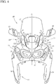
FIG. 4 is a front view of the front wind-shielding part. -
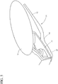
FIG. 5 is an upper perspective view of a mounted visor. -
FIG. 6 is a front view of the visor. -
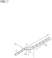
FIG. 7 is a cross-sectional view taken along line 7-7 inFIG. 6 . -
FIG. 8 is a front view of an upper lateral portion of a front wind-shielding part according to other embodiment. - In the following, a description will be given of an embodiment.
-
FIG. 1 is a perspective view of a saddled vehicle.FIG. 2 is a front view of the front part of the saddled vehicle.FIGS. 3 and4 are a perspective view and a front view of a front windshield device, respectively.FIG. 5 is an upper perspective view of a visor mounted on the vehicle body.FIG. 6 is a front view of the visor.FIG. 7 is a cross-sectional view taken along line 7-7 inFIG. 6 . -
FIG. 1 shows a saddled vehicle which is a tandem off-road motorcycle and includes: a front fork 10 (a front wheel suspension device) rotatably supported on a front part of a vehicle body frame (not shown); a front wheel 11 supported on a lower part of thefront fork 10; asteering handlebar 12 mounted on an upper part of thefront fork 10; atandem seat 13 disposed behind thehandlebar 12; arear wheel 14 disposed below theseat 13 and supported on the vehicle body frame; and anengine 15 disposed between the front wheel 11 and therear wheel 14 and supported on the vehicle body frame. - The
handlebar 12 is a bar-type handle, and a raised handle which is partially bent to raisehandle grips 12b (FIG. 2 ) on the longitudinal opposite ends. Thehandle grips 12b have their front side covered withhand guards 16. Thehand guards 16 protect the hand gripping the handlebar, and also function as windshield members for reducing the air pressure on thehandle grips 12b. - The
handlebar 12 has its front side covered with afront windshield device 19 made up of ascreen 17 and afront cowl 18. Thefront windshield device 19 guides the airflow toward the riders (adriver 51 and a pillion passenger 53) associated with the traveling to deflect the airflow from them. -
FIG. 1 shows aleg 51f of therider 51 put on afootrest 52, and apillion footrest 54 for thepassenger 53. - On the position above the
screen 17 and on the front side of thehandlebar 12,visors 20 formed of plate-like transparent resin are provided. Thevisors 20 are one of the air guide members. - In the vicinity of the
visors 20,turn signal lights 21 are provided to extend in the vehicle width direction, and overlap with the hand guards 16 as seen in a front view. This configuration disperses the airflow against the hand guards 16. - On the front end of the vehicle positioned below the
screen 17 and projecting frontward from thefront cowl 18, a right and left pair ofheadlights 22 are provided. - In the
front cowl 18, on the right and left sides of theheadlight 22,air ducts 23 are provided for taking in the air into the air cleaners which are not shown. - On the lateral sides of the
front cowl 18 at a level higher than theair ducts 23,upper deflectors 24 are provided lower than and in the vicinity of the turn signal lights 21. On the lateral sides and below thefront cowl 18 and on the front side of the rider's knees,lower deflectors 25 are provided. - The
upper deflectors 24 and thelower deflectors 25 are air management devices, which contribute to improving traveling stability at high speeds. - Other air management configurations include an
opening 26 provided at a lower central portion in thescreen 17,gaps 28 formed between thescreen 17 and thevisors 20, and thevisors 20. - The
visors 20, the turn signal lights 21, theair ducts 23, theupper deflectors 24, thelower deflectors 25, and thegaps 28 are provided to form right and left pairs on the vehicle. -
FIG. 2 is a front view of an upper lateral portion mainly showing the vicinity of thevisors 20 in the front part of the vehicle. With reference mainly toFIG. 2 and additionally toFIGS. 3 to 5 , a description will be given of the upper part configuration of thefront windshield device 19. Thescreen 17 is formed of transparent resin, has a vertically elongated shape, and mounted on the upper part of thefront cowl 18 so as to be inclined rearward. - The surface of the
screen 17 is a three-dimensional curved surface which is convex frontward to function as an airflow smoothing surface. In terms of the top-bottom direction, the curved surface extends rearward obliquely upward; and in terms of the right-left direction, the curved surface spreads rearward obliquely lateral outward. - The lower part of the
screen 17 is narrowed because of the provision of right and left recessedparts 30. Theopening 26 is formed at the center of the narrowed portion. Behind theopening 26, aguide member 27 is disposed so as to incline rearward to cover the rear side of theopening 26. Theguide member 27 is plate-like and has its lower part mounted on the upper part of thefront cowl 18, and has its upper part spaced apart from thescreen 17 so as to cause the air entering theopening 26 to flow upward along the back surface of thescreen 17. - The negative pressure caused on the rear surface side of the
screen 17 attributed to the air flowing along the surface of thescreen 17 is adjusted by the air entering theopening 26 and flowing along the back surface of thescreen 17. - The recessed
parts 30 are formed at right and left lower sides of thescreen 17 forming curves projecting toward the vehicle center (toward the center line CL). - On the outer lateral sides of the recessed
parts 30, upwardextended parts 31 are integrated with the upper part of thefront cowl 18 so as to project upward. The upwardextended parts 31 also are provided in a right and left pair. The upwardextended parts 31 are each a narrow part of the present invention. - The upward
extended parts 31 are disposed in the space outer than thescreen 17, which space is formed by the recessedparts 30. Between each upwardextended part 31 and thescreen 17, agap 28 is formed. The surface of each upwardextended part 31 functions as an airflow smoothing surface oriented frontward and obliquely outward. - Each upward
extended part 31 extends in the front-rear direction, and itsfront edge 31a is at a substantially similar position as the surface of thescreen 17. Between thefront edge 31a and the corresponding recessedpart 30, thegap 28 is formed. - A
rear edge 31b of the upwardextended part 31 is positioned outer than thefront edge 31a. - The airflow bent laterally outward at the lower surface of the
screen 17 and flowing rearward enters eachgap 28, and flows laterally outward along the rear surface of the upwardextended part 31. - On the other hand, the surface of the upward
extended part 31 is configured to guide laterally outward the air from the front and the airflow flowing along thescreen 17. The negative pressure occurring on the rear surface side of the upwardextended part 31 attributed to the air flowing along the surface of the upwardextended part 31 is adjusted by the air entering thegap 28 and flowing along the back surface of the upwardextended part 31. - The upward
extended part 31 is continuous to anupper surface 32 of thefront cowl 18. Theupper surface 32 functions as an airflow smoothing surface below thescreen 17 and over theheadlights 22, and forms a three-dimensional curved surface which extends rearward obliquely upward, and laterally outward and obliquely upward. - A
rear edge 32b of theupper surface 32 is continuous to therear edge 31b. This continuous part is shaped as a recessedpart 33 for clearing the path for the handlebar in steering. - The
handlebar 12 has a bent shape, in which the longitudinally intermediate part is bent upward to be raised, and again extends outward substantially horizontally, to form raisedparts 12a. Handlegrip parts 12b are provided at the longitudinally opposite ends of thehandlebar 12. - The recessed
part 33 is formed by having the rear part of the upwardextended part 31 and part of the rear part of thefront cowl 18 recessed so as not to interfere with the rotation range of the raisedpart 12a of thehandlebar 12 and thus to provide great steering angles of thehandlebar 12. As a result of being provided with the recessedpart 33, the upwardextended part 31 is reduced in width (the width in right-left direction), and formed as a narrow part which extends upward inner than the recessedpart 33. - This narrow portion is substantially the entire upward
extended part 31, and located on the front side of the raisedpart 12a of thehandlebar 12 and at a level higher than the raisedpart 12a. - At a lower part in the front surface of the upward
extended part 31, thevisor 20 is removably mounted by fixing elements such asbolts 34 so as to cover the front side of the recessedpart 33. Thevisor 20 functions as an airflow smoothing surface extending obliquely rearward and laterally outward form the upwardextended part 31. Thevisor 20 is disposed at a predetermined distance from the raisedpart 12a of thehandlebar 12 and thehand guard 16 so as to avoid interference with them. In the vicinity of thevisor 20 where it is mounted on the upwardextended part 31, anair guide port 43 opening frontward is formed. - Next, with reference to
FIGS. 5 to 7 , a description will be given mainly of the details of thevisor 20. - The
visor 20 is a plate-like member formed of transparent resin. Thevisor 20 curves from the inner side toward the outer side, and includes amount part 40, astep part 41, and anair guide part 42. - As shown in
FIG. 5 , themount part 40 is mounted along the surface of the upwardextended part 31, at upper and lower through holes 40a, 40a by the bolts 34 (FIG. 2 ), and extends laterally outward and rearward obliquely downward. - The
step part 41 is formed by thevisor 20 being valley-folded to form a substantially horizontal plane extending laterally outward, and oriented frontward.Reference character 41a indicates the valley-fold bent line. At thestep part 41, the upper and lower two pieces ofair guide ports 43 are provided. Note that, the upper and lowerair guide ports 43 may be continuous to each other to be one in number. Alternatively, three or more pieces ofair guide ports 43 may be provided. - Each
air guide port 43 opens frontward, and penetrates through thestep part 41. In the wall surface surrounding theair guide port 43, aninner wall surface 43a is an inclined surface in which the rear side is oriented laterally outward. As indicated by arrow a inFIG. 7 , thewall surface 43a bends the airflow entering theair guide port 43 so that the airflow flows laterally outward. - From a bent part 43b where the
visor 20 is mountain-folded on the outer side relative to thestep part 41, theair guide part 42 extends laterally outward and again rearward obliquely downward. The tip of theair guide part 42 extends to the vicinity of the hand guard 16 (seeFIG. 2 ). -
FIG. 5 schematically shows thehand guard 16 in the foremost position when the handlebar is steered by a maximum degree. In this manner, the tip of theair guide part 42 is disposed so as not to interfere with thehand guard 16 in the foremost position. - In particular, by virtue of the
visor 20 being formed stepwise by thestep part 41, theair guide part 42 is disposed frontward. This configuration allows thevisor 20 to extend on the front side of thehandlebar 12 and to extend itsair guide part 42 laterally outward while avoiding interference with thehandlebar 12. - As shown in
FIG. 6 , theleft visor 20 has a substantially quadrilateral shape, in which the upper side is partially inversely inclined. That is, defining that the four surrounding sides are anupper side 44, an innerlateral side 45, alower side 46, and an outerlateral side 47, theupper side 44 and thelower side 46 are substantially parallel to each other and extend in an upper right direction (with reference to the drawing's surface, the same holds true for the following). Similarly, the innerlateral side 45 and the outerlateral side 47 are substantially parallel to each other and extend in an upper right direction. - However, the
upper side 44 is bent downward by theair guide part 42. That is, theupper side 48 in theair guide part 42 inversely inclined, i.e., in a lower right direction, to be lower than thestep part 41. Thevisor 20 has a shape which would be obtained by removing, from a quadrilateral, atriangular portion 49 formed by extended lines of theupper side 44 and the outerlateral side 47 represented by phantom lines. - As a result, the top-bottom width of the
air guide part 42 is narrower on the outer side. Accordingly, theair guide part 42 has a highest height of H1 on thestep part 41 side, and has a lower height H2 than H1 on the outerlateral side 47 at the outer end. That is, the vertical width which is the top-bottom direction width also varies to be narrow laterally outward. - This configuration reduces the air pressure on the outer end side, and minimizes rattle.
- The right visor has symmetry with the left visor.
-
FIG. 7 illustrates the airflow on the front and back sides of theair guide part 42. The airflow toward thevisor 20 is bent laterally outward as indicated by arrow b by the surface of theair guide part 42, and flows toward the outerlateral side 47 while being smoothed along the surface. - On the other hand, part of the airflow enters the
air guide port 43 as indicated by arrow a, to exit to the back side of theair guide part 42. Here, the airflow is bent laterally outward by thewall surface 43a, and flows toward the outerlateral side 47 along the back surface of theair guide part 42. - Accordingly, the negative pressure occurring at the back surface of the
air guide part 42 attributed to the airflow on the front side (arrow b) is adjusted by the airflow, which is indicated by arrow a, formed on the rear surface side of theair guide part 42. - Next, with reference to
FIGS. 3 and4 , a description will be given of the whole configuration of thefront cowl 18. For the sake of convenience,FIG. 3 shows thevisors 20 as being separated. In a later process, thevisors 20 are mounted on the front side of the upwardextended part 31. - At the center of the
front cowl 18,headlight openings 36 for theheadlights 22 to be fitted into are provided. The lateral sides of theheadlight openings 36 formlateral parts 35 which function as airflow smoothing surfaces continuous to theupper surface 32 on the upper side. Thelateral parts 35 are each provided with a substantially V-shaped groove as seen in a front view extending in the front-rear direction. - Rear ends 35b of the
lateral parts 35 are continuous to therear edge 32b. - At front parts of the
lateral parts 35,air ducts 23 open. At rear parts of thelateral parts 35, theupper deflectors 24 are provided to cover the recessed parts, and open at rear ends 35b. - The
upper deflectors 24 function as airflow smoothing surfaces, and provided withopenings 24a opening frontward. Part of airflow on theupper deflectors 24 enters theupper deflectors 24 from theopenings 24a, and exits rearward from the rear ends 35b. - The lower part of the
headlight openings 36 form alower part 37 which is inverted U-shaped as seen in a front view, and covers a radiator 50 (FIG. 1 ). The right and left lateral parts form radiator shrouds 38, which cover the lateral sides of theradiator 50 and are provided withairflow exhaust ports 39. The radiator shrouds 38 are positioned on the front side of theknees 51d and the shins 51e of the rider 51 (FIG. 1 ). - In the rim around each
airflow exhaust port 39, the rear edge is widened, where the correspondinglower deflector 25 is provided. The lateral surface of thelower deflector 25 is juxtaposed to the rear part of the lower lateral surface of thecorresponding radiator shroud 38 and functions as an airflow smoothing surface. At the front surface of theradiator shroud 38, an opening 25b opening frontward is provided to penetrate in the front-rear direction. - The airflow passing through the lower part in the lateral surfaces of each
radiator shroud 38 exits theairflow exhaust port 39 and flows the outer lateral surface of thelower deflector 25. Part of this airflow enters the opening 25b to flow rearward, and adjusts the negative pressure on the rear side of thelower deflector 25. - Next, a description will be given of the operation of the present embodiment.
- In
FIG. 1 , part of air WD against thefront windshield device 19 is caused to flow upward by thescreen 17, and to spread rightward and leftward by thefront cowl 18. Thus, by diverting the air so as to avoid direct contact with the upper body of therider 51 and that of thepassenger 53 seated behind the rider, thefront windshield device 19 exhibits its wind-shielding effect. - Here, on the front side of the
handlebar 12, the recessedparts 33 are provided. Conventionally, part of the airflow passing through such recessed parts is brought into direct contact with thechest 51a and the arms (particularly the forearms 51b) of therider 51. This air pressure increasingly causes fatigue of the rider. In particular, the air pressure becomes greater when the rider is speeding faster, worsening the fatigue. - In the present embodiment, the
visors 20 are provided so as to cover the recessedparts 33. Thus, the airflow is curved on thevisors 20 to flow as indicated by arrow A over the shoulder laterally outward, and diverted away from therider 51 and thepassenger 53. - Thus, the upper body, particularly the
chest 51a and the arms (particularly the forearms 51b) are protected against the airflow, whereby fatigue in riding long hours or at high speeds is reduced. - As indicated by arrows a and b in
FIG. 7 , the airflow flowing on the front and back sides of eachvisor 20 adjusts the negative pressure occurring on the rear surface side of thevisor 20 thereby realizing air management. This contributes to improving traveling performance, in particular, to improving traveling stability at high speeds. - The present embodiment provides the recessed
parts 33 of great size and, therefore, provides great handle steering angles. Accordingly, the present embodiment is suitable to a vehicle requiring great handle steering angles, particularly an off-road vehicle. Additionally, provision of the hand guards 16 does not affect the handle steering angles and, therefore, the present embodiment is also suitable to a vehicle including the hand guards 16. That is, the present embodiment is optimum for an off-road vehicle including the hand guards 16 and requiring great steering angles. - As indicated by arrow B in
FIG. 1 , theupper deflectors 24 divert the airflow in an intermediate part in the top-bottom direction laterally outward from the abdomen (particularly the sides) 51c. Thus, the present embodiment particularly improves the wind-shielding performance on the abdomen (particularly the sides) 51c. - Additionally, the airflow flowing on the inner and outer sides of the
upper deflectors 24 realizes air management of adjusting the negative pressure occurring on the rear surface side of theupper deflector 24. This further contributes to improving the traveling performance. - As indicated by arrow C, the
lower deflectors 25 deflect the airflow in the lower part in the top-bottom direction laterally outward below theknees 51d. Thus, the present embodiment improves the wind-shielding performance on theknees 51d and the shins 51e. - Here, the airflow flowing on the inner and outer sides of the
lower deflectors 25 realizes air management of adjusting the negative pressure occurring on the rear surface side of thelower deflector 25. In particular, the present embodiment contributes to improving traveling performance at high speeds. - Furthermore, the
opening 26 realizes air management on thescreen 17, and thegaps 28 and the upwardextended parts 31 realize air management on the upwardextended parts 31. - By the
turn signal lights 21 being disposed so as to overlap with the hand guards 16 on the front side, theturn signal lights 21 disperse the air against the hand guards 16 thereby reducing the air pressure on the hand guards 16. - As a result of these elements achieving wind shielding and air management, fatigue is further reduced. This realizes stabilized longer-hour riding with reduced fatigue.
- The present invention is not limited to the embodiment above, and various applications and variations can be made. For example, instead of providing the upward
extended parts 31 at thefront cowl 18, the lower part of thescreen 17 may be widened rightward and leftward, and recesses may be formed on the right and left portions for clearing the path for the handlebar. -
FIG. 8 shows such a variation, and is other embodiment of the site shown inFIG. 2 . The elements similar to those of the foregoing embodiment are denoted by identical reference characters. - A
screen 17A according to the embodiment does not include the recessedparts 30 according to the foregoing embodiment. The lower right and left sides of thescreen 17A includes expandedparts 60 which correspond to the upwardextended parts 31. The expandedparts 60 has their lateral parts recessed to form recessedparts 61 which are continuous to therear edges 32b. The recessedparts 61 are continuous to therear edges 32b for clearing the path for the handlebar in steering similarly to the recessedparts 33 according to the foregoing embodiment. - The
gaps 28 are formed asholes 62 penetrating through thescreen 17A between the expandedparts 60 and theopening 26. Thevisors 20 are provided on the front side of the expandedparts 60 similarly to the foregoing embodiment. This configuration similarly improves the wind-shielding performance on thechest 51a and the forearms 51b of the rider 51 (seeFIG. 1 ) and still provides great handle steering angles by provision of the recessedparts 61 of thescreen 17A. - That is, the recessed parts (33, 61) for clearing the path for the handlebar in steering may be provided at one of or both of the
front cowl 18 and thescreen 17. In this regard, the recessedparts 33 may be provided at thefront windshield device 19. - A saddled vehicle to which the present invention is applied is not limited to an off-road vehicle, and may be any vehicle of various uses. The hand guards 16 may be dispensed with.
- The vehicle may not be a motorcycle, and may be a three-wheel vehicle or a four-wheel vehicle.
- The
handlebar 12 may not necessarily be a raised handle so long as it is a bar-type handle. - The present invention improves wind-shielding performance on the
chest 51a and the forearms 51b of therider 51 and still provides great handle steering angles, allowing the rider to ride for long hours with less fatigue. Therefore, the present invention is useful for a saddled vehicle including the front windshield device. -
- 12:
- handlebar
- 12a:
- raised part
- 16:
- hand guards
- 17, 17A:
- screen
- 18:
- front cowl
- 19:
- front windshield device
- 20:
- visor
- 31:
- upward extended part
- 33:
- recessed part
- 40:
- mount part
- 41:
- step part
- 42:
- air guide part
- 43:
- air guide port
- 61:
- recessed part
Claims (5)
- A saddled vehicle comprising:a front wheel suspension device (10);a handlebar (12) for steering the front wheel suspension device; anda front windshield device (19) includinga front cowl (18) covering an upper part of the front wheel suspension device and the handlebar from a front side; anda screen (17) disposed above the front cowl, whereinthe front windshield device (19) is provided with a recessed part (33) for clearing a path for the handlebar by being recessed on a front side relative to the handlebar,the front windshield device (19) includesa narrow part (31) narrowed by the recessed part (33) and extending on an inner side relative to the recessed part (33) upward from a height of the handlebar (12), anda visor (20) extending laterally outward from the narrow part (31) to cover a front side of the recessed part (33) and a front side of the handlebar (12), the visor (20) being disposed on a front side of the narrow part (31).
- The saddled vehicle according to claim 1, wherein
the visor (20) has its inner end mounted on the narrow part to be a mount part (40), and
the visor (20) includes a step part (41) being bent at the mount part and extending laterally outward, and an air guide part (42) being bent rearward at the step part and extending further laterally outward, a surface of the air guide part (42) functioning as an air guide surface. - The saddled vehicle according to claim 2, wherein the step part (41) of the visor (20) includes an air guide port (43).
- The saddled vehicle according to claim 1, wherein the air guide part (42) of the visor (20) has its height reduced outward.
- The saddled vehicle according to claim 1, wherein the handlebar (12) includes a hand guard (16) at each of its opposite ends.
Applications Claiming Priority (1)
| Application Number | Priority Date | Filing Date | Title |
|---|---|---|---|
| PCT/JP2017/021214 WO2018225199A1 (en) | 2017-06-07 | 2017-06-07 | Saddled vehicle |
Publications (3)
| Publication Number | Publication Date |
|---|---|
| EP3636525A1 true EP3636525A1 (en) | 2020-04-15 |
| EP3636525A4 EP3636525A4 (en) | 2020-07-01 |
| EP3636525B1 EP3636525B1 (en) | 2021-06-30 |
Family
ID=64567096
Family Applications (1)
| Application Number | Title | Priority Date | Filing Date |
|---|---|---|---|
| EP17912392.2A Active EP3636525B1 (en) | 2017-06-07 | 2017-06-07 | Saddled vehicle |
Country Status (3)
| Country | Link |
|---|---|
| EP (1) | EP3636525B1 (en) |
| JP (1) | JP6826663B2 (en) |
| WO (1) | WO2018225199A1 (en) |
Families Citing this family (3)
| Publication number | Priority date | Publication date | Assignee | Title |
|---|---|---|---|---|
| JP7223803B2 (en) * | 2021-03-31 | 2023-02-16 | 本田技研工業株式会社 | saddle-riding vehicle |
| JP7328290B2 (en) | 2021-08-30 | 2023-08-16 | 本田技研工業株式会社 | saddle-riding vehicle |
| JP2023098362A (en) | 2021-12-28 | 2023-07-10 | 本田技研工業株式会社 | Saddle-riding type vehicle |
Family Cites Families (12)
| Publication number | Priority date | Publication date | Assignee | Title |
|---|---|---|---|---|
| US4331358A (en) * | 1980-06-09 | 1982-05-25 | First Champaign Corporation | Motorcycle fairing body extender |
| JP4198286B2 (en) * | 1999-10-13 | 2008-12-17 | 本田技研工業株式会社 | Windshield device for bar handle type vehicle |
| US7347485B1 (en) * | 2004-07-23 | 2008-03-25 | Saunders Charles A | Exterior surface mounted adjustable wind deflector |
| JP2009061890A (en) * | 2007-09-05 | 2009-03-26 | Yamaha Motor Co Ltd | Motorcycle |
| JP2009173208A (en) * | 2008-01-25 | 2009-08-06 | Honda Motor Co Ltd | Windshield device for motorcycle |
| JP5728346B2 (en) * | 2011-09-20 | 2015-06-03 | 本田技研工業株式会社 | Vehicle front structure |
| JP6003477B2 (en) * | 2012-09-27 | 2016-10-05 | スズキ株式会社 | Handle cover device for motorcycle |
| EP2743161B1 (en) * | 2012-12-12 | 2016-04-06 | Suzuki Motor Corporation | Vehicle |
| CN105705410B (en) * | 2013-11-15 | 2018-09-25 | 川崎重工业株式会社 | Straddle-type vehicle |
| JP5922172B2 (en) * | 2014-03-19 | 2016-05-24 | 本田技研工業株式会社 | Front structure of motorcycle |
| JP6001615B2 (en) | 2014-09-30 | 2016-10-05 | 本田技研工業株式会社 | Saddle riding type vehicle |
| JP6051188B2 (en) * | 2014-09-30 | 2016-12-27 | 本田技研工業株式会社 | Saddle riding type vehicle |
-
2017
- 2017-06-07 WO PCT/JP2017/021214 patent/WO2018225199A1/en unknown
- 2017-06-07 JP JP2019523282A patent/JP6826663B2/en active Active
- 2017-06-07 EP EP17912392.2A patent/EP3636525B1/en active Active
Also Published As
| Publication number | Publication date |
|---|---|
| WO2018225199A1 (en) | 2018-12-13 |
| JPWO2018225199A1 (en) | 2020-03-19 |
| EP3636525B1 (en) | 2021-06-30 |
| JP6826663B2 (en) | 2021-02-03 |
| EP3636525A4 (en) | 2020-07-01 |
Similar Documents
| Publication | Publication Date | Title |
|---|---|---|
| EP3636525B1 (en) | Saddled vehicle | |
| EP2712794B1 (en) | Front cowl structure for saddle riding type vehicle | |
| US9868486B2 (en) | Saddle-ride type vehicle | |
| EP3002190B1 (en) | Saddle-type ride vehicle | |
| EP3072791B1 (en) | Straddle-type vehicle | |
| US9663155B2 (en) | Motorcycle body cover construction | |
| US8662230B2 (en) | Saddle-type vehicle | |
| EP2436583B1 (en) | Fairing structure for straddle-ride type vehicle | |
| EP3072792B1 (en) | Straddle type vehicle with cowling structure | |
| EP3418168A1 (en) | Saddle riding vehicle | |
| EP2481657A2 (en) | Saddle-ride type vehicle | |
| CN102285402B (en) | Saddle-ride type vehicle | |
| EP2428437A1 (en) | Leg shield structure of saddle-ride-type vehicle | |
| JP2023159161A (en) | Ride comfort enhanced ridable saddle vehicle with windshield | |
| JP4322289B2 (en) | Windscreen mounting structure | |
| EP3002188B1 (en) | Saddle-type ride vehicle | |
| CN215475512U (en) | Saddle-ride type vehicle | |
| EP2712795B1 (en) | Straddle-type vehicle | |
| CN218141908U (en) | Windproof structure for saddle-ride type vehicle | |
| WO2015071937A1 (en) | Saddled vehicle | |
| JPWO2019229669A5 (en) | ||
| JPH04208683A (en) | Motorcycle |
Legal Events
| Date | Code | Title | Description |
|---|---|---|---|
| STAA | Information on the status of an ep patent application or granted ep patent |
Free format text: STATUS: THE INTERNATIONAL PUBLICATION HAS BEEN MADE |
|
| PUAI | Public reference made under article 153(3) epc to a published international application that has entered the european phase |
Free format text: ORIGINAL CODE: 0009012 |
|
| STAA | Information on the status of an ep patent application or granted ep patent |
Free format text: STATUS: REQUEST FOR EXAMINATION WAS MADE |
|
| 17P | Request for examination filed |
Effective date: 20200103 |
|
| AK | Designated contracting states |
Kind code of ref document: A1 Designated state(s): AL AT BE BG CH CY CZ DE DK EE ES FI FR GB GR HR HU IE IS IT LI LT LU LV MC MK MT NL NO PL PT RO RS SE SI SK SM TR |
|
| AX | Request for extension of the european patent |
Extension state: BA ME |
|
| A4 | Supplementary search report drawn up and despatched |
Effective date: 20200529 |
|
| RIC1 | Information provided on ipc code assigned before grant |
Ipc: B62J 17/02 20060101AFI20200525BHEP Ipc: B62J 17/10 20200101ALI20200525BHEP Ipc: B62J 23/00 20060101ALI20200525BHEP |
|
| DAV | Request for validation of the european patent (deleted) | ||
| DAX | Request for extension of the european patent (deleted) | ||
| REG | Reference to a national code |
Ref country code: DE Ref legal event code: R079 Ref document number: 602017041479 Country of ref document: DE Free format text: PREVIOUS MAIN CLASS: B62J0017000000 Ipc: B62J0017100000 |
|
| GRAP | Despatch of communication of intention to grant a patent |
Free format text: ORIGINAL CODE: EPIDOSNIGR1 |
|
| STAA | Information on the status of an ep patent application or granted ep patent |
Free format text: STATUS: GRANT OF PATENT IS INTENDED |
|
| RIC1 | Information provided on ipc code assigned before grant |
Ipc: B62J 17/04 20060101ALI20210129BHEP Ipc: B62J 17/02 20060101ALI20210129BHEP Ipc: B62J 17/10 20200101AFI20210129BHEP Ipc: B62J 23/00 20060101ALI20210129BHEP |
|
| INTG | Intention to grant announced |
Effective date: 20210219 |
|
| GRAS | Grant fee paid |
Free format text: ORIGINAL CODE: EPIDOSNIGR3 |
|
| GRAA | (expected) grant |
Free format text: ORIGINAL CODE: 0009210 |
|
| STAA | Information on the status of an ep patent application or granted ep patent |
Free format text: STATUS: THE PATENT HAS BEEN GRANTED |
|
| AK | Designated contracting states |
Kind code of ref document: B1 Designated state(s): AL AT BE BG CH CY CZ DE DK EE ES FI FR GB GR HR HU IE IS IT LI LT LU LV MC MK MT NL NO PL PT RO RS SE SI SK SM TR |
|
| REG | Reference to a national code |
Ref country code: CH Ref legal event code: EP |
|
| REG | Reference to a national code |
Ref country code: AT Ref legal event code: REF Ref document number: 1406134 Country of ref document: AT Kind code of ref document: T Effective date: 20210715 |
|
| REG | Reference to a national code |
Ref country code: DE Ref legal event code: R096 Ref document number: 602017041479 Country of ref document: DE |
|
| REG | Reference to a national code |
Ref country code: IE Ref legal event code: FG4D |
|
| REG | Reference to a national code |
Ref country code: LT Ref legal event code: MG9D |
|
| PG25 | Lapsed in a contracting state [announced via postgrant information from national office to epo] |
Ref country code: BG Free format text: LAPSE BECAUSE OF FAILURE TO SUBMIT A TRANSLATION OF THE DESCRIPTION OR TO PAY THE FEE WITHIN THE PRESCRIBED TIME-LIMIT Effective date: 20210930 Ref country code: HR Free format text: LAPSE BECAUSE OF FAILURE TO SUBMIT A TRANSLATION OF THE DESCRIPTION OR TO PAY THE FEE WITHIN THE PRESCRIBED TIME-LIMIT Effective date: 20210630 Ref country code: FI Free format text: LAPSE BECAUSE OF FAILURE TO SUBMIT A TRANSLATION OF THE DESCRIPTION OR TO PAY THE FEE WITHIN THE PRESCRIBED TIME-LIMIT Effective date: 20210630 |
|
| REG | Reference to a national code |
Ref country code: NL Ref legal event code: MP Effective date: 20210630 |
|
| REG | Reference to a national code |
Ref country code: AT Ref legal event code: MK05 Ref document number: 1406134 Country of ref document: AT Kind code of ref document: T Effective date: 20210630 |
|
| PG25 | Lapsed in a contracting state [announced via postgrant information from national office to epo] |
Ref country code: GR Free format text: LAPSE BECAUSE OF FAILURE TO SUBMIT A TRANSLATION OF THE DESCRIPTION OR TO PAY THE FEE WITHIN THE PRESCRIBED TIME-LIMIT Effective date: 20211001 Ref country code: SE Free format text: LAPSE BECAUSE OF FAILURE TO SUBMIT A TRANSLATION OF THE DESCRIPTION OR TO PAY THE FEE WITHIN THE PRESCRIBED TIME-LIMIT Effective date: 20210630 Ref country code: RS Free format text: LAPSE BECAUSE OF FAILURE TO SUBMIT A TRANSLATION OF THE DESCRIPTION OR TO PAY THE FEE WITHIN THE PRESCRIBED TIME-LIMIT Effective date: 20210630 Ref country code: LV Free format text: LAPSE BECAUSE OF FAILURE TO SUBMIT A TRANSLATION OF THE DESCRIPTION OR TO PAY THE FEE WITHIN THE PRESCRIBED TIME-LIMIT Effective date: 20210630 Ref country code: NO Free format text: LAPSE BECAUSE OF FAILURE TO SUBMIT A TRANSLATION OF THE DESCRIPTION OR TO PAY THE FEE WITHIN THE PRESCRIBED TIME-LIMIT Effective date: 20210930 |
|
| PG25 | Lapsed in a contracting state [announced via postgrant information from national office to epo] |
Ref country code: RO Free format text: LAPSE BECAUSE OF FAILURE TO SUBMIT A TRANSLATION OF THE DESCRIPTION OR TO PAY THE FEE WITHIN THE PRESCRIBED TIME-LIMIT Effective date: 20210630 Ref country code: NL Free format text: LAPSE BECAUSE OF FAILURE TO SUBMIT A TRANSLATION OF THE DESCRIPTION OR TO PAY THE FEE WITHIN THE PRESCRIBED TIME-LIMIT Effective date: 20210630 Ref country code: PT Free format text: LAPSE BECAUSE OF FAILURE TO SUBMIT A TRANSLATION OF THE DESCRIPTION OR TO PAY THE FEE WITHIN THE PRESCRIBED TIME-LIMIT Effective date: 20211102 Ref country code: CZ Free format text: LAPSE BECAUSE OF FAILURE TO SUBMIT A TRANSLATION OF THE DESCRIPTION OR TO PAY THE FEE WITHIN THE PRESCRIBED TIME-LIMIT Effective date: 20210630 Ref country code: AT Free format text: LAPSE BECAUSE OF FAILURE TO SUBMIT A TRANSLATION OF THE DESCRIPTION OR TO PAY THE FEE WITHIN THE PRESCRIBED TIME-LIMIT Effective date: 20210630 Ref country code: SK Free format text: LAPSE BECAUSE OF FAILURE TO SUBMIT A TRANSLATION OF THE DESCRIPTION OR TO PAY THE FEE WITHIN THE PRESCRIBED TIME-LIMIT Effective date: 20210630 Ref country code: SM Free format text: LAPSE BECAUSE OF FAILURE TO SUBMIT A TRANSLATION OF THE DESCRIPTION OR TO PAY THE FEE WITHIN THE PRESCRIBED TIME-LIMIT Effective date: 20210630 Ref country code: EE Free format text: LAPSE BECAUSE OF FAILURE TO SUBMIT A TRANSLATION OF THE DESCRIPTION OR TO PAY THE FEE WITHIN THE PRESCRIBED TIME-LIMIT Effective date: 20210630 Ref country code: ES Free format text: LAPSE BECAUSE OF FAILURE TO SUBMIT A TRANSLATION OF THE DESCRIPTION OR TO PAY THE FEE WITHIN THE PRESCRIBED TIME-LIMIT Effective date: 20210630 |
|
| PG25 | Lapsed in a contracting state [announced via postgrant information from national office to epo] |
Ref country code: PL Free format text: LAPSE BECAUSE OF FAILURE TO SUBMIT A TRANSLATION OF THE DESCRIPTION OR TO PAY THE FEE WITHIN THE PRESCRIBED TIME-LIMIT Effective date: 20210630 |
|
| REG | Reference to a national code |
Ref country code: DE Ref legal event code: R097 Ref document number: 602017041479 Country of ref document: DE |
|
| PG25 | Lapsed in a contracting state [announced via postgrant information from national office to epo] |
Ref country code: DK Free format text: LAPSE BECAUSE OF FAILURE TO SUBMIT A TRANSLATION OF THE DESCRIPTION OR TO PAY THE FEE WITHIN THE PRESCRIBED TIME-LIMIT Effective date: 20210630 |
|
| PLBE | No opposition filed within time limit |
Free format text: ORIGINAL CODE: 0009261 |
|
| STAA | Information on the status of an ep patent application or granted ep patent |
Free format text: STATUS: NO OPPOSITION FILED WITHIN TIME LIMIT |
|
| PG25 | Lapsed in a contracting state [announced via postgrant information from national office to epo] |
Ref country code: AL Free format text: LAPSE BECAUSE OF FAILURE TO SUBMIT A TRANSLATION OF THE DESCRIPTION OR TO PAY THE FEE WITHIN THE PRESCRIBED TIME-LIMIT Effective date: 20210630 |
|
| 26N | No opposition filed |
Effective date: 20220331 |
|
| PG25 | Lapsed in a contracting state [announced via postgrant information from national office to epo] |
Ref country code: IT Free format text: LAPSE BECAUSE OF FAILURE TO SUBMIT A TRANSLATION OF THE DESCRIPTION OR TO PAY THE FEE WITHIN THE PRESCRIBED TIME-LIMIT Effective date: 20210630 |
|
| REG | Reference to a national code |
Ref country code: DE Ref legal event code: R084 Ref document number: 602017041479 Country of ref document: DE |
|
| PG25 | Lapsed in a contracting state [announced via postgrant information from national office to epo] |
Ref country code: MC Free format text: LAPSE BECAUSE OF FAILURE TO SUBMIT A TRANSLATION OF THE DESCRIPTION OR TO PAY THE FEE WITHIN THE PRESCRIBED TIME-LIMIT Effective date: 20210630 |
|
| REG | Reference to a national code |
Ref country code: CH Ref legal event code: PL |
|
| REG | Reference to a national code |
Ref country code: BE Ref legal event code: MM Effective date: 20220630 |
|
| GBPC | Gb: european patent ceased through non-payment of renewal fee |
Effective date: 20220607 |
|
| PG25 | Lapsed in a contracting state [announced via postgrant information from national office to epo] |
Ref country code: LU Free format text: LAPSE BECAUSE OF NON-PAYMENT OF DUE FEES Effective date: 20220607 Ref country code: LT Free format text: LAPSE BECAUSE OF FAILURE TO SUBMIT A TRANSLATION OF THE DESCRIPTION OR TO PAY THE FEE WITHIN THE PRESCRIBED TIME-LIMIT Effective date: 20210630 Ref country code: LI Free format text: LAPSE BECAUSE OF NON-PAYMENT OF DUE FEES Effective date: 20220630 Ref country code: IE Free format text: LAPSE BECAUSE OF NON-PAYMENT OF DUE FEES Effective date: 20220607 Ref country code: FR Free format text: LAPSE BECAUSE OF NON-PAYMENT OF DUE FEES Effective date: 20220630 Ref country code: CH Free format text: LAPSE BECAUSE OF NON-PAYMENT OF DUE FEES Effective date: 20220630 |
|
| PG25 | Lapsed in a contracting state [announced via postgrant information from national office to epo] |
Ref country code: GB Free format text: LAPSE BECAUSE OF NON-PAYMENT OF DUE FEES Effective date: 20220607 Ref country code: BE Free format text: LAPSE BECAUSE OF NON-PAYMENT OF DUE FEES Effective date: 20220630 |
|
| PGFP | Annual fee paid to national office [announced via postgrant information from national office to epo] |
Ref country code: DE Payment date: 20230412 Year of fee payment: 7 |
|
| PG25 | Lapsed in a contracting state [announced via postgrant information from national office to epo] |
Ref country code: MK Free format text: LAPSE BECAUSE OF FAILURE TO SUBMIT A TRANSLATION OF THE DESCRIPTION OR TO PAY THE FEE WITHIN THE PRESCRIBED TIME-LIMIT Effective date: 20210630 Ref country code: CY Free format text: LAPSE BECAUSE OF FAILURE TO SUBMIT A TRANSLATION OF THE DESCRIPTION OR TO PAY THE FEE WITHIN THE PRESCRIBED TIME-LIMIT Effective date: 20210630 |