WO2018220950A1 - ガス発生器、及びデュアルタイプのガス発生器の組立方法 - Google Patents
ガス発生器、及びデュアルタイプのガス発生器の組立方法 Download PDFInfo
- Publication number
- WO2018220950A1 WO2018220950A1 PCT/JP2018/010504 JP2018010504W WO2018220950A1 WO 2018220950 A1 WO2018220950 A1 WO 2018220950A1 JP 2018010504 W JP2018010504 W JP 2018010504W WO 2018220950 A1 WO2018220950 A1 WO 2018220950A1
- Authority
- WO
- WIPO (PCT)
- Prior art keywords
- housing
- generating agent
- igniter
- combustion chamber
- gas generating
- Prior art date
- Legal status (The legal status is an assumption and is not a legal conclusion. Google has not performed a legal analysis and makes no representation as to the accuracy of the status listed.)
- Ceased
Links
Images




Classifications
-
- F—MECHANICAL ENGINEERING; LIGHTING; HEATING; WEAPONS; BLASTING
- F42—AMMUNITION; BLASTING
- F42B—EXPLOSIVE CHARGES, e.g. FOR BLASTING, FIREWORKS, AMMUNITION
- F42B3/00—Blasting cartridges, i.e. case and explosive
- F42B3/04—Blasting cartridges, i.e. case and explosive for producing gas under pressure
-
- B—PERFORMING OPERATIONS; TRANSPORTING
- B60—VEHICLES IN GENERAL
- B60R—VEHICLES, VEHICLE FITTINGS, OR VEHICLE PARTS, NOT OTHERWISE PROVIDED FOR
- B60R21/00—Arrangements or fittings on vehicles for protecting or preventing injuries to occupants or pedestrians in case of accidents or other traffic risks
- B60R21/02—Occupant safety arrangements or fittings, e.g. crash pads
- B60R21/16—Inflatable occupant restraints or confinements designed to inflate upon impact or impending impact, e.g. air bags
- B60R21/23—Inflatable members
- B60R21/235—Inflatable members characterised by their material
-
- B—PERFORMING OPERATIONS; TRANSPORTING
- B60—VEHICLES IN GENERAL
- B60R—VEHICLES, VEHICLE FITTINGS, OR VEHICLE PARTS, NOT OTHERWISE PROVIDED FOR
- B60R21/00—Arrangements or fittings on vehicles for protecting or preventing injuries to occupants or pedestrians in case of accidents or other traffic risks
- B60R21/02—Occupant safety arrangements or fittings, e.g. crash pads
- B60R21/16—Inflatable occupant restraints or confinements designed to inflate upon impact or impending impact, e.g. air bags
- B60R21/26—Inflatable occupant restraints or confinements designed to inflate upon impact or impending impact, e.g. air bags characterised by the inflation fluid source or means to control inflation fluid flow
-
- B—PERFORMING OPERATIONS; TRANSPORTING
- B60—VEHICLES IN GENERAL
- B60R—VEHICLES, VEHICLE FITTINGS, OR VEHICLE PARTS, NOT OTHERWISE PROVIDED FOR
- B60R21/00—Arrangements or fittings on vehicles for protecting or preventing injuries to occupants or pedestrians in case of accidents or other traffic risks
- B60R21/02—Occupant safety arrangements or fittings, e.g. crash pads
- B60R21/16—Inflatable occupant restraints or confinements designed to inflate upon impact or impending impact, e.g. air bags
- B60R21/26—Inflatable occupant restraints or confinements designed to inflate upon impact or impending impact, e.g. air bags characterised by the inflation fluid source or means to control inflation fluid flow
- B60R21/264—Inflatable occupant restraints or confinements designed to inflate upon impact or impending impact, e.g. air bags characterised by the inflation fluid source or means to control inflation fluid flow using instantaneous generation of gas, e.g. pyrotechnic
-
- B—PERFORMING OPERATIONS; TRANSPORTING
- B60—VEHICLES IN GENERAL
- B60R—VEHICLES, VEHICLE FITTINGS, OR VEHICLE PARTS, NOT OTHERWISE PROVIDED FOR
- B60R21/00—Arrangements or fittings on vehicles for protecting or preventing injuries to occupants or pedestrians in case of accidents or other traffic risks
- B60R21/02—Occupant safety arrangements or fittings, e.g. crash pads
- B60R21/16—Inflatable occupant restraints or confinements designed to inflate upon impact or impending impact, e.g. air bags
- B60R21/23—Inflatable members
- B60R21/235—Inflatable members characterised by their material
- B60R2021/23504—Inflatable members characterised by their material characterised by material
- B60R2021/23519—Resin
-
- B—PERFORMING OPERATIONS; TRANSPORTING
- B60—VEHICLES IN GENERAL
- B60R—VEHICLES, VEHICLE FITTINGS, OR VEHICLE PARTS, NOT OTHERWISE PROVIDED FOR
- B60R21/00—Arrangements or fittings on vehicles for protecting or preventing injuries to occupants or pedestrians in case of accidents or other traffic risks
- B60R21/02—Occupant safety arrangements or fittings, e.g. crash pads
- B60R21/16—Inflatable occupant restraints or confinements designed to inflate upon impact or impending impact, e.g. air bags
- B60R21/23—Inflatable members
- B60R21/235—Inflatable members characterised by their material
- B60R2021/23504—Inflatable members characterised by their material characterised by material
- B60R2021/23528—Metal
-
- B—PERFORMING OPERATIONS; TRANSPORTING
- B60—VEHICLES IN GENERAL
- B60R—VEHICLES, VEHICLE FITTINGS, OR VEHICLE PARTS, NOT OTHERWISE PROVIDED FOR
- B60R21/00—Arrangements or fittings on vehicles for protecting or preventing injuries to occupants or pedestrians in case of accidents or other traffic risks
- B60R21/02—Occupant safety arrangements or fittings, e.g. crash pads
- B60R21/16—Inflatable occupant restraints or confinements designed to inflate upon impact or impending impact, e.g. air bags
- B60R21/26—Inflatable occupant restraints or confinements designed to inflate upon impact or impending impact, e.g. air bags characterised by the inflation fluid source or means to control inflation fluid flow
- B60R2021/26029—Ignitors
Definitions
- the present invention relates to a gas generator that generates a combustion gas by burning a gas generating agent by operating an igniter.
- the combustion gas is designed if the filled gas generating agent does not burn as desired. It becomes difficult to generate on the street.
- its housing is generally made of metal so that it can withstand the pressure generated by the combustion of the gas generating agent.
- the gas generating agent may be powdered by contact with the housing.
- the surface area of the gas generant is increased compared to that before pulverization, so the combustion characteristics of the gas generant may change and the gas generant combustion may not be achieved as designed. There is. Further, such unnecessary movement of the gas generating agent can be a cause of sound generation when it vibrates.
- a disk-shaped cushion member is disposed so as to come into contact with the gas generating agent filled in the housing from the vertical direction of the housing.
- the gas generating agent charged in the combustion chamber in the housing of the gas generator is manufactured from the time the gas generator is manufactured to its operation. Powdering should be avoided and its shape should be maintained as much as possible.
- the cushioning material is only disposed in the vertical direction in the combustion chamber in order to avoid pulverization of the gas generating agent.
- the gas generating agent avoids contact with an object other than the cushion member in the vertical direction of the combustion chamber by the cushion material, but on the other hand, contact between the gas generating agent and another object on the side of the combustion chamber. Occurs. For this reason, if vibration is applied to the gas generator, the gas generating agent may be powdered or vibrated due to the contact, so there is room for improvement.
- an object of the present invention is to provide a technique for suppressing powdering of a gas generating agent filled in a housing of a gas generator and generation of vibration noise.
- the present invention employs a structure in which a resin isolation wall is interposed between the side and bottom surfaces of the combustion chamber of the gas generator and the gas generating agent filled in the combustion chamber. With such a configuration, it is possible to suppress unnecessary movement of the gas generating agent by applying a predetermined holding force to the gas generating agent.
- the gas generator of the present invention is an igniter and a metal housing that houses the igniter and forms a gas discharge port, and is in a position where combustion is possible by the operation of the igniter.
- a housing having a combustion chamber in which the filled solid gas generating agent is combusted, and the gas generating agent disposed in the combustion chamber inside the housing and the bottom and side surfaces of the combustion chamber.
- an isolation member having an isolation wall made of a predetermined resin material so as to be in contact with the gas generating agent and to give a predetermined holding force to the gas generating agent.
- an igniter is accommodated in a housing, and a combustion chamber formed therein is filled with a gas generating agent.
- combustion of the gas generating agent is realized.
- the combustion chamber is defined by a part of the housing, for example, an inner wall surface of the housing, or is defined by an object other than the housing and disposed in the housing, the combustion chamber is filled.
- the gas generant will be in direct contact with the object defining the combustion chamber.
- the gas generating agent may be powdered.
- the combustion chamber is defined by the inner wall surface of the housing, since the housing is made of metal, the gas generating agent is easily powdered. In addition, it may cause vibration noise due to the gas generating agent.
- the gas generating agent defines the combustion chamber by interposing the isolation wall of the isolation member between the bottom and side surfaces of the combustion chamber and the gas generating agent filled therein.
- a predetermined holding force is applied to the gas generating agent from the isolation wall while avoiding a state of direct contact with the object.
- the isolation wall is a part of the configuration of the isolation member and is interposed between the gas generating agent and the bottom and side surfaces of the combustion chamber as described above.
- the isolation member may be formed only of the isolation wall, or may be formed including a configuration other than the isolation wall. This predetermined holding force is applied from the resin-made isolation wall so that the gas generating agent in the combustion chamber does not move in the combustion chamber in order to suppress pulverization of the gas generating agent.
- the isolation wall of the isolation member avoids the gas generating agent from contacting the bottom surface and the side surface of the combustion chamber, and provides the above-mentioned predetermined holding force to the gas generating agent in a state where the combustion chamber is filled. What is necessary is just to be comprised so that it may provide. Therefore, the isolation wall may be formed of a material having a hardness lower than that of the housing. The isolation wall may be formed of a material having a hardness lower than that of the gas generating agent. As an example, the isolation wall can be made of resin. In addition, when the gas generating agent is filled into the combustion chamber, a predetermined holding force is effectively applied from the isolation wall, so that the isolation wall is not deformed when it comes into contact with the filled gas generating agent.
- This deformation may be elastic deformation or plastic deformation. By deforming in this way, it is possible to effectively maintain the contact between the isolation wall and the gas generating agent, and suppress the generation of pulverization and vibration noise due to unnecessary movement of the gas generating agent by the buffering action. Is possible.
- the isolation member may be formed so as to cover all of the bottom surface and the side surface of the combustion chamber with the isolation wall. With such a configuration, contact between the gas generating agent and the bottom and side surfaces of the combustion chamber can be avoided more reliably.
- the contact of a gas generating agent and the bottom face and side surface of a combustion chamber should just be avoided. Therefore, as long as the contact can be avoided, it is not necessary for the isolation wall to cover the bottom surface and side surface of the combustion chamber, and the bottom surface and part of the side surface may be covered with the isolation wall. Absent.
- the isolation member may be integrally formed of the predetermined resin material. By integrally forming the isolation member in this way, it is possible to reduce the assembly load required for the arrangement of the isolation member in the housing and the like regarding the assembly of the gas generator. Needless to say, in the gas generator of the present invention, the isolation member may be formed of a plurality of members.
- a part of the side surface of the combustion chamber is defined by a predetermined inner wall surface of the housing, and in this case, between the isolation wall and the predetermined inner wall surface of the housing.
- the isolation member may be disposed in the housing such that a gap is formed in the housing.
- the gap is formed between the side surface of the combustion chamber defined by the predetermined inner wall surface and the isolation wall, so that the isolation wall becomes the predetermined inner wall surface when the gas generating agent is filled in the combustion chamber. It becomes possible to be displaced or deformed toward the surface, and a predetermined holding force can be continuously applied stably to the filled gas generating agent, so that powdering can be avoided.
- the isolation wall has a plurality of resin protrusions extending toward the inside of the combustion chamber in a state where the isolation member is disposed in the housing.
- the plurality of protrusions may be formed to be deformable by a force received from the gas generating agent filled in the combustion chamber.
- the combustion chamber is filled with a solid explosive in addition to the gas generant, and the separator is burned by the operation of the igniter.
- the transfer charge is disposed around the igniter, and the transfer charge isolation wall is defined so that the transfer charge and the gas generating agent are not mixed before the start of the igniter.
- at least the isolation wall for the charge transfer agent may be formed of a material that deforms, breaks, burns, or melts as the transfer charge burns.
- the gas generating agent in the housing is finally burned through the combustion of the transfer charge.
- the explosive charge may be another gas generant housed separately from the gas generant in the housing, or may be a conventional explosive such as black powder.
- the transfer charge and the gas generating agent be suitably separated and disposed in the housing before the igniter is operated. is there. This is because if both are mixed, combustion of the gas generating agent cannot be realized as designed. Therefore, in the above gas generator, it is possible to dispose the transfer charge around the ignition charge so as not to coexist with the gas generation charge by providing the isolation member with a transfer charge isolation wall. When the igniter is activated, the transfer charge isolation wall is deformed, destroyed, burned, or melted by the combustion of the transfer charge, so that the combustion of the transfer charge can cause the combustion of the gas generating agent without any trouble. As described above, in the gas generator, the separation member suitably suppresses the pulverization of the gas generating agent and prevents the mixture of the transfer agent and the gas generating agent in the housing.
- the housing includes a metal first housing in which the gas discharge port is formed, and a metal second housing disposed below the first housing.
- the housing includes a dividing wall which divides the combustion chamber into upper and lower parts and forms a first combustion chamber located on the upper side and a second combustion chamber located on the lower side.
- a first igniter that burns the first gas generating agent filled in the first combustion chamber, and a second gas generating agent that is the gas generating agent filled in the second combustion chamber.
- a second igniter different from the first igniter is disposed, and the dividing wall surrounds the first igniter and accommodates the first igniter in the first combustion chamber.
- a first igniter housing that extends into the second housing; And a side surface of the second combustion chamber is defined by an inner wall surface of the second housing and a predetermined outer peripheral wall surface of the first igniter housing portion located in the second housing,
- the isolation wall may be interposed between the bottom and side surfaces of the second combustion chamber and the second gas generating agent filled in the second combustion chamber.
- the gas generator is a so-called dual type gas generator in which two igniters are mounted, and the combustion chamber is formed to overlap in the vertical direction of the housing, thereby increasing the lateral width of the gas generator. Therefore, the gas output can be increased.
- the first igniter and the second igniter are arranged on the second housing side, the dividing wall that divides the inside of the housing into the first combustion chamber located above and the second combustion chamber located below is The first igniter accommodating portion that accommodates the first igniter disposed in the second housing so as to surround the first igniter is included in the first combustion chamber. Therefore, the second combustion chamber located below is generally a space excluding the first igniter housing portion in the internal space of the second housing, and its side surfaces are the inner wall surface of the second housing and the first igniter. It becomes a predetermined outer peripheral wall surface of the housing portion. Therefore, in the dual type gas generator, the isolation wall of the isolation member is formed so as to correspond to the second combustion chamber having such a shape.
- the present invention can be grasped from the aspect of the assembly method of the dual type gas generator. That is, the present invention has a housing composed of a metal first housing having a gas discharge port and a metal second housing disposed below the first housing, and the first housing is disposed in the housing.
- This is a method of assembling a dual-type gas generator that includes one igniter and a second igniter different from the first igniter, and combusts the corresponding first gas generating agent and second gas generating agent.
- the housing divides the combustion chamber into upper and lower parts, and is located on the upper side and the lower side of the first combustion chamber filled with the first gas generating agent.
- the side surface of the second combustion chamber is defined by an inner wall surface of the second housing and a predetermined outer peripheral wall surface of the first igniter housing portion located in the second housing.
- the isolation member is attached to the second housing so as to insert the first igniter housing portion into a predetermined space formed by the igniter surrounding wall, and the second combustion chamber is formed below the isolation member And placing the first gas generating agent above the isolation member attached to the second housing at a position combustible by the operation of the first igniter and sealing with the first housing. And forming the first combustion chamber.
- the gas generator is a dual type gas generator in which two combustion chambers are arranged vertically in a housing. In order to assemble such a gas generator, it is necessary to sequentially stack the components constituting the gas generator. In particular, since the space in the housing is divided into two combustion chambers vertically by the dividing wall, it is necessary to assemble the gas generator in the order of the second housing, the dividing wall, and the first housing.
- the second gas generating agent is configured to be held in the predetermined filling space of the separating member, so that the separating member functions as a retainer for the second gas generating agent, and the gas generating agent is disposed. Can be prevented from collapsing.
- the first partition wall is formed in the predetermined space formed by the first igniter surrounding wall of the isolation member in a state in which the predetermined filling space of the isolation member is filled with the second gas generating agent.
- the second gas generating agent is supplied to the second combustion chamber. While suppressing direct contact, unnecessary movement of the second gas generating agent can be suppressed, and thus powdering can be suppressed.
- the present invention it is possible to suppress pulverization of the gas generating agent filled in the housing of the gas generator and generation of vibration noise.
- FIG. 4 is a top view of the isolation member shown in FIG. 3. It is an enlarged view of the site
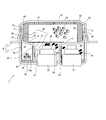
- FIG. 1 is a sectional view in the height direction of the gas generator 1
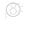
- FIG. 2 is a top view of a lower shell 3 (second housing) included in the gas generator 1.
- the gas generator 1 is configured to burn a gas generating agent filled in a housing 4 formed by an upper shell 2 (first housing) and a lower shell 3 to release combustion gas.
- the gas generator 1 is a so-called dual type gas generator in which two combustion chambers are arranged vertically and a corresponding igniter and a gas generating agent are arranged in each combustion chamber.
- the upper shell 2 has a peripheral wall portion 2c and a top surface portion 2d, thereby forming a concave internal space.
- the top surface portion 2d has a substantially circular shape in top view together with the bottom surface portion 3b of the lower shell 3 described later, and the peripheral wall portion 2c and the peripheral wall portion 3a of the lower shell 3 described later include the top surface portion 2d and the bottom surface portion, respectively.
- An annular wall surface that surrounds 3b and extends substantially vertically from each surface portion is formed.
- the internal space of the upper shell 2 becomes a first combustion chamber 21 filled with a first transfer charge 24 and a first gas generating agent 22 as will be described later.
- the top surface portion 2 d is connected to one end side of the peripheral wall portion 2 c, and the other end side is an opening of the upper shell 2.
- fitting wall part 2a and the abutting part 2b are provided in the said other end side of the surrounding wall part 2c in an order from the said opening part.
- the radius of the internal space by the fitting wall portion 2a is formed larger than the radius of the internal space by the peripheral wall portion 2c near the top surface portion 2d, and the fitting wall portion 2a is connected to the peripheral wall portion 2c through the abutting portion 2b. ing.
- the lower shell 3 has a peripheral wall portion 3a and a bottom surface portion 3b, thereby forming a concave internal space.
- the internal space becomes a second combustion chamber 28 filled with the second transfer charge 26 and the second gas generating agent 29 as will be described later.
- the bottom surface portion 3 b is connected to one end side of the peripheral wall portion 3 a, and the other end side is an opening of the lower shell 3.
- the radius of the internal space by the peripheral wall portion 3 a is substantially the same as the radius of the internal space by the peripheral wall portion 2 c of the upper shell 2. 2, the bottom shell 3b of the lower shell 3 is provided with a fitting hole 3c and a fitting hole 3d for fixing the first igniter 23 and the second igniter 27, as will be described later. Yes.
- a dividing wall 10 is disposed in the housing 4 between the upper shell 2 and the lower shell 3.
- the dividing wall 10 includes an end portion 15, a fitting wall portion 14 extending from the end portion 15 along the peripheral wall portion 3 a of the lower shell 3, and the upper and lower spaces in the housing 4 connected to the fitting wall portion 14.
- the dividing wall 13 is the top surface of the upper shell 2. 2d and a wall surface substantially parallel to the bottom surface portion 3b of the lower shell 3 are formed, and the peripheral wall portion 12 forms a space (accommodating space 20 described later) recessed from the wall surface of the divided wall portion 13 toward the lower shell 3 side. In this way, it is connected to the dividing wall portion 13.
- the peripheral wall portion 12 is provided with a through hole 10a that is a through hole.
- the through hole 10a is divided into two spaces formed by the dividing wall 10 (a first combustion chamber 21 and a second combustion described later).
- the chamber 28) communicates.
- the recessed space 20 is opened to the upper space side, and the first igniter 23 is accommodated as will be described later. Therefore, the recessed space 20 is simply referred to as “accommodating space 20”.
- the through hole 10a is closed by a closing member 35 from the accommodation space 20 side. With such a configuration, a difference occurs in the burst pressure of the closing member 35, and the closing member 35 is cleaved only when the second igniter 27 is operated in the second combustion chamber 28 described later. Further, the attachment edge portion 11 forms a through-hole through which the first igniter 23 fixed to the fitting hole 3 c of the lower shell 3 is inserted.
- the upper shell 2 is further attached from above with the dividing wall 10 attached on the lower shell 3 in this way.
- the abutting portion 2b of the upper shell 2 has the dividing wall 10. Until it is abutted against the end 15 of the lower shell 3.
- the fitting wall portion 14 is fitted to the peripheral wall portion 3 a of the lower shell 3.
- the fitting part and the contact part of the upper shell 2 and the lower shell 3 are joined by a joining method (for example, welding or the like) suitable for moisture-proofing the gas generating agent filled therein. .
- the internal space is divided into two spaces in the vertical direction by the dividing wall 10.
- a first igniter 23, a first transfer charge 24, and a first gas generating agent 22 are arranged, and the lower shell
- the second igniter 27, the second transfer charge 26, and the second gas generating agent 29 are arranged in the second combustion chamber 28 defined by 3 and the dividing wall 10.
- the gas generator is configured as a dual type gas generator including a first igniter 23 and a second igniter 27.
- the first igniter 23 and the second igniter 27 are both fixed on the bottom surface portion 3b of the lower shell 3.
- the first igniter 23 is located on the side of the first igniter 23 at the dividing wall 10b. It is in the state accommodated in the accommodation space 20 so that it may be surrounded by the surrounding wall part 12, and the top part may not jump out from the division
- the first igniter 23 is accommodated in the accommodating space 20 which is a part of the first combustion chamber 21, and the first explosive 24 is filled therewith.
- the first transfer charge 24 a gas generating agent having good ignitability and a combustion temperature higher than that of the first gas generating agent 22 can be used.
- the combustion temperature of the first transfer charge 24 can be in the range of 1700 to 3000 ° C.
- a disk-shaped material made of, for example, nitroguanidine (34% by weight) and strontium nitrate (56% by weight) can be used.
- the opening of the accommodation space 20 is closed with the aluminum tape 36, and the first gas filled in the space above the accommodation space 20 (generally, the space above the dividing wall portion 13). Mixing with the generator 22 is prevented.
- the space above the aluminum tape 36 that blocks the opening of the accommodation space 20 is filled with the first gas generating agent 22.
- An annular filter 32 is disposed so as to surround the.
- the first gas generating agent 22 is filled in a state in which the first gas generating agent 22 is suppressed to the filter 32, the dividing wall portion 13 and the like by the urging force of the cushion 31 so as not to vibrate unnecessarily in the first combustion chamber 21.
- a gas generating agent having a combustion temperature lower than that of the first transfer charge 24 is used as the first gas generating agent 22.
- the combustion temperature of the first gas generating agent 22 is preferably in the range of 1000 to 1700 ° C., and includes, for example, guanidine nitrate (41 wt%), basic copper nitrate (49 wt%), and a binder or additive.
- a single-hole cylindrical shape can be used.
- the filter 32 is formed by superposing a flat steel mesh made of stainless steel in the radial direction and compressing it in the radial direction and the axial direction, cooling the combustion gas by the first gas generating agent 22, and removing the combustion residue. Collect.
- the filter 32 may be a winding type structure formed by winding a wire around a mandrel in multiple layers. Note that the filter 32 also collects combustion residues of the second gas generating agent 29 filled in the second combustion chamber 28.
- an annular gas passage is formed in the radial cross section around the filter 32 by a gap 33 formed between the peripheral wall portion 2 c of the upper shell 2 and the filter 32.
- the combustion gas passes through the entire region of the filter 32, and effective use of the filter 32 and effective cooling and purification of the combustion gas are achieved.
- the combustion gas flowing through the gap 33 reaches the gas discharge port 5 provided in the peripheral wall 2c. Further, in order to prevent moisture from entering the housing 4 from the outside, the gas discharge port 5 is closed from the inside of the housing 4 by the aluminum tape 34 before the operation of the gas generator 1.
- the second combustion chamber 28 has an inner wall surface of the peripheral wall portion 3 a of the lower shell 3 and an outer peripheral surface of the peripheral wall portion 12 of the dividing wall 10 as side surfaces, a bottom surface portion 3 b of the lower shell 3 as a bottom surface, and a dividing wall of the dividing wall 10. It is a space defined with the portion 13 as an upper surface.
- the 2nd transfer charge 26 the thing like a pellet form, a column shape, etc. which consist of nitroguanidine (34 weight%) and strontium nitrate (56 weight%) is used like the 1st transfer charge 24, for example.
- the second gas generating agent 29 for example, as with the first gas generating agent 22, for example, guanidine nitrate (41% by weight), basic copper nitrate (49% by weight), a binder and an additive are used. A cylindrical hole can be used.
- the second gas generating agent 29 etc. are in contact with the outer peripheral surface of the metallic lower shell 3 or the peripheral wall portion 12 of the dividing wall 10 extending into the lower shell 3 (the wall defining the accommodating space 20 is the back wall) and powdered.
- a separating member 40 made of resin is disposed in the lower shell 3.
- the isolation member 40 will be described with reference to FIGS.
- FIG. 3 is a perspective view of the separating member 40
- FIG. 4 is a top view of the separating member 40.
- the AA cross section in FIG. 4 will be in the state of the isolation member 40 shown in FIG.
- the isolation member 40 is entirely formed of the same resin material, and the resin material is melted by the combustion heat of the second charge transfer agent 26 and the second gas generating agent 29 filled in the second combustion chamber 28.
- Material Specifically, the separating member 40 includes an annular outer peripheral wall portion 42, an annular inner peripheral wall portion 44, and a bottom wall portion 43 that forms a bottom wall surface of the separating member 40 that is connected perpendicularly to both peripheral wall portions. Have.
- the outer wall surface 42 b of the outer peripheral wall portion 42 faces the inner wall surface of the peripheral wall portion 3 a of the lower shell 3, and the inner wall surface 44 a of the inner peripheral wall portion 44 is divided.
- the bottom wall portion 43 is in contact with the bottom surface portion 3 b of the lower shell 3 in contact with the outer wall surface of the peripheral wall portion 12 of the wall 10.
- a lower edge portion 41 is formed on the lower portion of the outer peripheral wall portion 42 so as to protrude outward by a minute height. Therefore, a gap 50 between the outer wall surface 42b of the outer peripheral wall portion 42 and the inner wall surface of the peripheral wall portion 3a of the lower shell 3 is set according to the protruding amount of the lower edge portion 41 as shown in FIG. Is formed.
- the inner peripheral wall portion 44 is arranged to face the outer wall surface of the peripheral wall portion 12 of the dividing wall 10, it corresponds to the first igniter surrounding wall of the present invention.
- the predetermined space 47 surrounded by the inner peripheral wall portion 44 is opened above and below the lower space 3, and the lower opening portion is in a state where the isolation member 40 is disposed on the lower shell 3. It is formed so as to correspond to the fitting hole 3c provided in.
- positioned at the lower shell 3 can be in the state penetrated by the isolation member 40 in the state accommodated in the accommodation space 20 of the dividing wall 10, as shown in FIG.
- the space between the inner wall surface 42 a of the outer peripheral wall portion 42 and the outer wall surface 44 b of the inner peripheral wall portion 44 is a space filled with the second transfer charge 26 and the second gas generating agent 29.
- the separating member 40 includes a pair of partition walls 45 and 46 that are set up vertically with respect to the bottom wall portion 43, and connects the inner peripheral wall portion 44 and the outer peripheral wall portion 42.
- partition walls 45 and 46 are provided with partition walls 45 and 46 for defining a charge transfer chamber 25 in which the second transfer charge 26 is separated and filled so as not to be mixed with the second gas generating agent 29.
- the partition parts 45 and 46 are equivalent to the isolation wall for explosives of this invention.
- the second gas generating agent 29 is filled in a space other than the transfer charge filling chamber 25 in the predetermined filling space.
- the ratio between the volume of the charge transfer agent filling chamber 25 and the volume of the space filled with the second gas generating agent 29 in the predetermined filling space may be appropriately determined according to the output characteristics to be generated by the gas generator 1. .
- a through hole 48 is provided below the transfer charge filling chamber 25 so as to correspond to the fitting hole 3 d provided in the lower shell 3. Thereby, the 2nd igniter 27 arrange
- the isolation member 40 configured in this manner is disposed on the lower shell 3 and incorporated in the housing 4, and is a peripheral wall portion of the lower shell 3 that is a side surface of the second combustion chamber 28.
- the inner wall surface of 3 a and the outer peripheral surface of the peripheral wall portion 12 of the dividing wall 10 are covered and the bottom surface portion 3 b of the lower shell 3 that is the bottom surface of the second combustion chamber 28 is covered and shaped.
- the inner wall surface 44 a of the inner peripheral wall portion 44 is in a state of closing the through hole 10 a provided in the peripheral wall portion 12 of the dividing wall 10.
- the separating member 40 is formed of a resin material that can be melted by the combustion heat of the second gas generating agent 29 or the like, there is no problem in the distribution of the combustion gas by the second gas generating agent 29 or the like.
- a through hole may be provided in a portion of the inner peripheral wall portion 44 facing the through hole 10a so as not to block the through hole 10a.
- the separating member 40 has a pair of partition walls 45 and 46, both of them are separated and filled in the second combustion chamber 28 so that the second transfer powder 26 is not mixed in the second gas generating agent 29. be able to.
- the isolation member 40 is made of a resin material, and its hardness is lower than the hardness of the metal lower shell 3. Further, since the isolation member 40 has a lower hardness than the second transfer powder 26 and the second gas generating agent 29, the buffering against the second gas generating agent 29 and the like filled in a predetermined filling space in the isolation member 40 is provided. A suitable holding force can be applied by the action. The holding force is a force capable of suppressing unnecessary movement of the second gas generating agent 29 and the like by being applied to the second gas generating agent 29 and the like.
- a gap 50 is formed between the outer wall surface 42 b of the outer peripheral wall portion 42 and the lower shell 3 by the lower edge portion 41 provided at the lower portion of the isolation member 40. .
- the gap 50 enables deformation and displacement of the outer peripheral wall portion 42 toward the lower shell 3 side when a predetermined filling space of the isolation member 40 is filled with the second gas generating agent 29 and the like. Therefore, the filling makes it easy to generate a holding force required for the second gas generating agent 29 and the like. Alternatively, if the holding force can be generated when filling the second gas generating agent or the like, the gap 50 is not necessarily required, and thus the separating member 40 does not need to be provided with the lower edge 41. .
- the upper edge protrudes outwardly to the same extent as the lower edge portion 41.
- the part 42c may be provided.
- a gap 50 is formed between the outer wall surface 42b and the lower shell 3, and the outer peripheral wall portion 42 can be largely displaced in the vicinity of the middle abdomen, thereby suitably generating the holding force. be able to.
- the outer peripheral wall portion 42 is excessively deformed when the second gas generating agent 29 or the like is filled. You can avoid it.
- the separating member 40 is interposed between the second gas generating agent 29 and the like and the side surface and the bottom surface of the second combustion chamber 28, thereby pulverizing the second gas generating agent 29 and the like in the second combustion chamber 28. And generation of vibration noise by the second gas generating agent 29 and the like can be suitably suppressed.
- the gas generator 1 comprised including the isolation member 40, when the 1st igniter 23 act
- the aluminum tape 36 prevents the first transfer powder 24 and the first gas generating agent 22 from being mixed.
- the combustion gas by the 1st gas generating agent 22 is discharge
- the second igniter 27 is operated next to the first igniter 23, whereby the second transfer charge 26 is ignited, and then the second gas generating agent 29 is combusted.
- the isolation member 40 prevents the second explosive 26 and the second gas generating agent 29 from being mixed, and the pulverization of the second gas generating agent 29 and the like is suppressed.
- the combustion gas by the second gas generating agent 29 can be generated as designed.
- the combustion gas passes through the through-hole 10a, passes through the first combustion chamber 21, and is discharged to the outside from the gas discharge port 5.
- the assembly method of the gas generator 1 is demonstrated based on FIG.
- the separating member 40 is also made to function as a retainer for maintaining the arrangement position in order to suitably arrange the second transfer agent 26 and the second gas generating agent 29 in the second combustion chamber 28.
- the gas generator 1 is assembled by steps 1 to 9. Details of each step will be described below.
- step 1 the first igniter 23 and the second igniter 27 are attached to the fitting holes 3 c and 3 d of the lower shell 3, respectively, and both igniters are arranged on the bottom surface of the lower shell 3.
- the separating member 40 is disposed on the lower shell 3. At this time, the first igniter 23 is inserted into the predetermined space 47 through the opening of the predetermined space 47 of the isolation member 40, and the second igniter 27 is inserted into the transfer charge filling chamber 25 through the through hole 48.
- step 3 the second charge transfer agent 26 is filled in the charge transfer charge filling chamber 25, and the second gas generating agent 29 is filled in the remaining portion of the predetermined filling space of the isolation member 40.
- the second gas generating agent 29 and the like are in a state where the above-described holding force is applied from the resin isolation member 40, and this state is maintained by the outer peripheral wall portion 42 and the inner peripheral wall portion 44 of the isolation member 40. The Therefore, when the dividing wall 10 is attached to the lower shell 3 in the next step 4, inadvertent contact between the dividing wall 10 and the second gas generating agent 29 or the like can be suitably avoided.
- step 4 the dividing wall 10 is attached to the lower shell 3 so that the peripheral wall portion 12 of the dividing wall 10 is inserted into the predetermined space 47 of the separating member 40 arranged in the lower shell 3.
- the second combustion chamber 28 is formed by the dividing wall 10 and the lower shell 3, and the second gas generating agent 29 and the like are accommodated in the second combustion chamber 28 while being filled in the isolation member 40. .
- step 5 the first explosive 24 is filled in the space surrounded by the peripheral wall portion 12 of the dividing wall 10 inserted into the predetermined space 47, that is, in the accommodation space 20.
- the space 20 is closed with an aluminum tape 36.
- step 7 the filter 32 is disposed on the dividing wall portion 13 of the dividing wall 10, and in step 8, the first gas generating agent 22 is filled in the central portion of the filter 32.
- step 9 the upper shell 2 is attached to the lower shell 3 together with the cushion 31. As a result, the first combustion chamber 21 is formed by the upper shell 2 and the dividing wall 10, and the assembly of the gas generator 1 is completed.
- the separating member 40 is the second gas generating agent burned in the second combustion chamber 28. 29, etc., in other words, since it has a function of securing an insertion space when the peripheral wall portion 12 of the dividing wall 10 is inserted into the second combustion chamber 28, it is divided.
- the wall 10 can be easily attached to the lower shell 3, and crushing of the second gas generating agent 29 and the like can be avoided during assembly.
- the separating member 40 is integrally formed of a resin material, the operations of Step 2 to Step 4 are particularly easy.
- FIG. 7 is an enlarged view of a portion where the outer peripheral wall portion 42 and the lower shell 3 are in contact with each other with respect to the separating member 40 disposed in the lower shell 3.
- the isolation member 40 of this modification differs from the isolation member 40 of the above embodiment in that the lower edge 41 is not provided below the outer peripheral wall portion 42 and the inner wall surface side of the outer peripheral wall portion 42 The point is that a plurality of resin-made protrusions 42d extending to a predetermined filling space side filled with the two gas generating agents 29 and the like are provided.
- the protrusion 42d is formed of the same resin material as the resin material of the main body of the isolation member 40 so as to be deformable by receiving a force from the filled gas generating agent 29 or the like.
- the isolation member 40 by filling the isolation member 40 with the second gas generating agent 29 or the like so that the plurality of projecting portions 42d are appropriately deformed, the above-described holding force is applied to the second gas generating agent 29 or the like. It can form suitably.
- the lower edge portion 41 shown in FIG. 5 may be provided, and the gap 50 may be formed between the outer peripheral wall portion 42 and the lower shell 3.
- the gas generator 1 of the above-mentioned Example is a dual type gas generator, also in the single type gas generator provided with one igniter, the combustion chamber formed in the said gas generator A resin isolation member may be interposed so as to avoid direct contact between the side and bottom surfaces of the gas generating agent and the gas generating agent filled therein. Also in this case, it is preferable that the isolation member is a material that melts by the combustion heat of the gas generating agent.
- the isolation member 40 is formed as one component, but the isolation member 40 may be formed by a plurality of components.
- Gas generator 2 Upper shell 3: Lower shell 4: Housing 5: Gas discharge port 10: Dividing wall 12: Peripheral wall part 13: Dividing wall part 14: Fitting wall part 20: Accommodating space 21: First combustion chamber 22: 1st gas generating agent 23: 1st igniter 24: 1st transfer powder 25: Transfer charge filling chamber 26: 2nd transfer powder 27: 2nd igniter 28: 2nd combustion chamber 29: 2nd gas generating agent 40: isolation member 41: lower edge 42: outer peripheral wall 42c: upper edge 42d: protrusion 43: bottom wall 44: inner peripheral wall 47: predetermined space 50: gap
Landscapes
- Engineering & Computer Science (AREA)
- Mechanical Engineering (AREA)
- Physics & Mathematics (AREA)
- Fluid Mechanics (AREA)
- General Engineering & Computer Science (AREA)
- Air Bags (AREA)
Abstract
ガス発生器において、点火器と、点火器を収容しガス排出口を形成した金属製のハウジングであって、該点火器の作動により、燃焼可能となる位置に充填された固形のガス発生剤の燃焼が行われる燃焼室を有するハウジングと、ハウジングの内部において燃焼室に配置されたガス発生剤と該燃焼室の底面及び側面との間に介在し、該ガス発生剤と接触して該ガス発生剤に対して所定の保持力を付与するように所定の樹脂材料で形成された隔離壁を有する隔離部材と、を備える。このような構成により、ガス発生器のハウジング内に充填されたガス発生剤の粉化と振動音の発生を抑制する。
Description
本発明は、点火器の作動によりガス発生剤を燃焼させて燃焼ガスを発生させるガス発生器に関する。
点火器の作動により燃焼室内に充填されたガス発生剤を燃焼させ、燃焼ガスを発生させるガス発生器においては、当該充填されたガス発生剤が所望するように燃焼しなければ、燃焼ガスを設計通りに発生させることが困難となる。ここで、ガス発生器については、ガス発生剤の燃焼により生じた圧力に耐え得るように、一般にはそのハウジングは金属製とされる。しかし、金属製のハウジング内にガス発生剤が充填された場合、仮にハウジング内でガス発生剤が不要に移動してしまうと、ハウジングとの接触によりガス発生剤が粉化する可能性がある。粉化したガス発生剤では、粉化する前と比べてガス発生剤の表面積が増加するためガス発生剤の燃焼特性が変化してしまい、設計通りのガス発生剤の燃焼が得られない可能性がある。また、このような不要なガス発生剤の移動は、振動した際の音の発生要因ともなり得る。
そこで、例えば特許文献1に示す技術では、ハウジング内に充填されたガス発生剤に対して、ハウジングの上下方向から接触するようにディスク状のクッション部材が配置されている。このようなクッション部材の緩衝機能を利用することで、ハウジング内でのガス発生剤の移動阻止が図られる。
ガス発生器の使用時における出力特性を設計通りに実現するためには、ガス発生器の製造時からその作動時までの間、ガス発生器のハウジング内の燃焼室に充填されたガス発生剤の粉化は回避すべきでありその形状は可及的に維持されている必要がある。しかし、従来技術では、ガス発生剤の粉化を回避するために燃焼室内の上下方向においてクッション材を配置するのみである。この場合、ガス発生剤はクッション材により燃焼室の上下方向においてクッション部材以外の物体との接触は回避されているが、一方で、燃焼室の側方におけるガス発生剤と他の物体との接触が生じる。そのため、ガス発生器に対して振動が付与されるとその接触に起因してガス発生剤の粉化や振動音が生じ得ることから、改善の余地がある。
本発明は、上記した問題に鑑み、ガス発生器のハウジング内に充填されたガス発生剤の粉化と振動音の発生を抑制する技術を提供することを目的とする。
上記課題を解決するために、本発明は、ガス発生器の燃焼室の側面及び底面と、該燃焼室に充填されるガス発生剤の間に樹脂製の隔離壁を介在させる構成を採用した。このような構成により、ガス発生剤に所定の保持力を作用させてガス発生剤の不要な移動を抑制することが可能となる。
具体的には、本発明のガス発生器は、点火器と、前記点火器を収容しガス排出口を形成した金属製のハウジングであって、該点火器の作動により、燃焼可能となる位置に充填された固形のガス発生剤の燃焼が行われる燃焼室を有するハウジングと、前記ハウジングの内部において前記燃焼室に配置された前記ガス発生剤と該燃焼室の底面及び側面との間に介在し、該ガス発生剤と接触して該ガス発生剤に対して所定の保持力を付与するように所定の樹脂材料で形成された隔離壁を有する隔離部材と、を備える。
本発明のガス発生器では、ハウジング内に点火器が収容されるとともに、そこに形成された燃焼室にガス発生剤が充填されている。点火器の作動により、そのガス発生剤の燃焼が実現される。ここで、当該燃焼室がハウジングの一部、例えば、ハウジングの内壁面によって画定されたり、ハウジング以外の構成物であってハウジング内に配置される物体によって画定されたりすると、燃焼室に充填されたガス発生剤が、燃焼室を画定する物体に直接接触することになる。このような接触状態があるときに、外部からの加振によりガス発生器が振動してしまうと、ガス発生剤が粉化してしまう可能性がある。特に、燃焼室がハウジングの内壁面によって画定される場合には、ハウジングが金属製であるためガス発生剤の粉化が生じやすくなる。また、ガス発生剤による振動音が発生する原因にもなる。
そこで、本発明のガス発生器では、隔離部材の隔離壁を、燃焼室の底面及び側面とそこに充填されるガス発生剤との間に介在させることで、ガス発生剤が燃焼室を画定する物体に直接接触する状態を回避しながら、隔離壁からガス発生剤に対して所定の保持力を付与する。なお、隔離壁は、隔離部材の構成の一部であり、上記の通りガス発生剤と燃焼室の底面及び側面との間に介在される物である。隔離部材は、隔離壁のみで形成されてもよく、隔離壁以外の構成を含んで形成されてもよい。この所定の保持力は、ガス発生剤の粉化を抑制するために、燃焼室内のガス発生剤がその燃焼室内で移動しないように樹脂製の隔離壁から付与されるものである。
すなわち、隔離部材の隔離壁は、ガス発生剤が燃焼室の底面及び側面に接触するのを回避するとともに、燃焼室に充填された状態においてそのガス発生剤に対して上述した所定の保持力を付与するように構成されればよい。そのために、隔離壁は、ハウジングの硬度よりも低い硬度の材質で形成されてもよい。また、隔離壁は、ガス発生剤の硬度よりも低い硬度の材質で形成されてもよい。その一例として、隔離壁は樹脂製とすることができる。また、ガス発生剤が燃焼室に充填された際に隔離壁から所定の保持力が効果的に付与されるために、隔離壁は、充填されたガス発生剤に対して接触した際に変形が可能な材料であってもよい。この変形は、弾性変形でもよく塑性変形でもよい。このように変形することで、隔離壁とガス発生剤との接触を効果的に維持することができ、ガス発生剤の不要な移動による粉化と振動音の発生をその緩衝作用によって抑制することが可能となる。
また、上記のガス発生器において、前記隔離部材は、前記隔離壁で前記燃焼室の底面及び側面の全てを覆うように形成されてもよい。このような構成により、ガス発生剤と燃焼室の底面及び側面との接触をより確実に回避させることができる。なお、上記の通り、ガス発生剤の粉化を抑制するためには、ガス発生剤と燃焼室の底面及び側面との接触が回避されればよい。したがって、当該接触の回避が可能である限りにおいては、隔離壁が燃焼室の底面及び側面を全て覆う必要はなく、底面や側面の一部が隔離壁に覆われている状態であっても構わない。
また、上述までのガス発生器において、前記隔離部材は、前記所定の樹脂材料で一体に形成されてもよい。このように一体で隔離部材を形成することで、ガス発生器の組み立てに関し、ハウジング内での隔離部材の配置等に要する組立負荷を軽減することができる。なお、本発明のガス発生器において、隔離部材を、複数の部材で形成しても構わないことは言うまでもない。
ここで、上述までのガス発生器において、前記燃焼室の側面の一部は、前記ハウジングの所定の内壁面により画定され、その場合、前記隔離壁と前記ハウジングの前記所定の内壁面との間に間隙が形成されるように、前記隔離部材は、前記ハウジング内に配置されてもよい。このように所定の内壁面によって画定される燃焼室の側面と隔離壁との間に間隙が形成されることで、ガス発生剤が燃焼室に充填されたときに隔離壁が所定の内壁面に向かって変位し又は変形することが可能となり、充填されたガス発生剤に対して安定して所定の保持力を付与し続けることができ、以てその粉化を回避することができる。
また、上述までのガス発生器において、前記隔離壁は、前記隔離部材が前記ハウジング内に配置された状態で、前記燃焼室の内側に向かって延出した、樹脂製の複数の突起部を有し、前記複数の突起部は、前記燃焼室に充填された前記ガス発生剤から受ける力で変形可能に形成されてもよい。このように樹脂製の複数の突起部が隔離壁に設けられることで、燃焼室に充填されたガス発生剤との接触性が高められ、以て、充填されたガス発生剤に対して安定して所定の保持力を付与し続けることができ、以てその粉化を回避することができる。なお、当該突起部の大きさは、接触するガス発生剤の破損等を回避するために、当該ガス発生剤の大きさに対して十分に小さいのが好ましい。
ここで、上述までのガス発生器において、前記燃焼室に、前記ガス発生剤に加えて、固形の伝火薬が充填され、前記隔離部材は、前記点火器の作動により前記伝火薬が燃焼されるように該伝火薬を該点火器の周囲に配置するとともに、該点火器の作動前には該伝火薬と前記ガス発生剤とが混在しないように伝火薬充填室を画定する伝火薬用隔離壁を、更に有し、少なくとも前記伝火薬用隔離壁は、前記伝火薬の燃焼に伴って変形、破壊、燃焼、又は溶融する材料で形成されてもよい。当該ガス発生器では、点火器の作動を起点として、伝火薬の燃焼を介して最終的にハウジング内のガス発生剤が燃焼されることになる。ここで、伝火薬としては、ハウジング内において上記ガス発生剤とは分離して収容されている別のガス発生剤でもよく、別法として、従来の黒色火薬等の火薬であってもよい。
このように伝火薬の燃焼を介して最終的にガス発生剤を燃焼させる場合、点火器の作動前には伝火薬とガス発生剤とが好適に分離されてハウジング内に配置されている必要がある。両者が混在してしまうと、ガス発生剤の燃焼を設計通りに実現させることができなくなるからである。そこで、上記ガス発生器では、隔離部材に伝火薬用隔離壁を設けることで、伝火薬を点火薬の周りに、且つガス発生剤と混在しないように配置することが可能となる。そして、点火器が作動すると、この伝火薬用隔離壁は伝火薬の燃焼によって変形、破壊、燃焼、又は溶融するため、支障なく伝火薬の燃焼がガス発生剤の燃焼を引き起こすことができる。このように上記ガス発生器では、隔離部材により、ガス発生剤の粉化抑制とともに、ハウジング内での伝火薬とガス発生剤の混在防止が好適に図られることになる。
ここで、上述までのガス発生器において、前記ハウジングは、前記ガス排出口を形成した金属製の第1ハウジングと、該第1ハウジングの下方に配置される、金属製の第2ハウジングとからなり、前記ハウジングは、その内部に、前記燃焼室を上下に分割し、上側に位置する第1燃焼室と下側に位置する第2燃焼室を形成する分割壁を含み、前記第2ハウジングの底面に、前記第1燃焼室に充填された第1ガス発生剤を燃焼する第1点火器と、前記第2燃焼室に充填された、前記ガス発生剤である第2ガス発生剤を燃焼する前記点火器であり該第1点火器とは異なる第2点火器とが配置され、前記分割壁は、前記第1点火器を取り囲み前記第1燃焼室内に該第1点火器を収容するように前記第2ハウジング内に延出した第1点火器収容部を形成し、前記第2燃焼室の側面は、前記第2ハウジングの内壁面及び該第2ハウジング内に位置する前記第1点火器収容部の所定の外周壁面により画定され、前記隔離部材は、前記第2ハウジングの内部において、前記第2燃焼室の底面及び側面と該第2燃焼室に充填された前記第2ガス発生剤との間に前記隔離壁を介在させてもよい。
上記ガス発生器は、2つの点火器が搭載される、いわゆるデュアルタイプのガス発生器であり、燃焼室がハウジングの上下方向に重ねて形成されることで、ガス発生器の横幅を大きくすることなくそのガス出力の増強を図ることができる。ここで、第2ハウジング側に第1点火器と第2点火器が配置されるため、ハウジング内を上方に位置する第1燃焼室と下方に位置する第2燃焼室に分割する分割壁は、第2ハウジングに配置された第1点火器を第1燃焼室に含めて該第1点火器を取り囲むように収容する第1点火器収容部を形成することになる。そのため、下方に位置する第2燃焼室は、概ね、第2ハウジングの内部空間のうち第1点火器収容部を除いた空間となり、その側面は、第2ハウジングの内壁面、及び第1点火器収容部の所定の外周壁面となる。そこで、上記のデュアルタイプのガス発生器では、このような形状を有する第2燃焼室に対応するように隔離部材の隔離壁が形成される。
ここで、本願発明をデュアルタイプのガス発生器の組立方法の側面から捉えることができる。すなわち、本願発明は、ガス排出口を形成した金属製の第1ハウジングと、該第1ハウジングの下方に配置される、金属製の第2ハウジングとからなるハウジングを有し、該ハウジング内に第1点火器と該第1点火器と異なる第2点火器とを備え、それぞれに対応する第1ガス発生剤と第2ガス発生剤を燃焼させるデュアルタイプのガス発生器の組立方法である。そして、前記ハウジングは、その内部に、前記燃焼室を上下に分割し、上側に位置し前記第1ガス発生剤が充填される第1燃焼室と下側に位置し前記第2ガス発生剤が充填される第2燃焼室を形成する分割壁を含み、前記分割壁は、前記第1点火器を取り囲んで収容するように前記第2ハウジング内に延出した第1点火器収容部を形成し、前記第2燃焼室の側面は、前記第2ハウジングの内壁面及び該第2ハウジング内に位置する前記第1点火器収容部の所定の外周壁面により画定される。この場合、前記組立方法は、前記第2ハウジングの底面に、前記第1点火器と前記第2点火器とを配置するステップと、前記第2燃焼室の底面及び側面と前記第2ガス発生剤との接触を阻止し、且つ該第2ガス発生剤を充填する所定の充填空間を形成し該所定の充填空間に充填された該第2ガス発生剤に対して所定の保持力を付与するように、所定の樹脂材料で形成された隔離壁を有する隔離部材を、前記第2ハウジングの内部に配置するステップと、前記隔離部材の前記所定の充填空間に前記第2ガス発生剤を充填し、該充填された第2ガス発生剤に前記所定の保持力が付与された状態を形成するステップと、前記第2ハウジングに配置された前記隔離部材の前記隔離壁のうち、前記第1点火器収容部の所定の外周壁面に対応する、環状の第1点火器包囲壁によって形成される所定空間に、前記第1点火器収容部を挿入するように該隔離部材を該第2ハウジングに取り付けて、該隔離部材の下方に前記第2燃焼室を形成するステップと、前記第2ハウジングに取り付けられた前記隔離部材の上方に前記第1点火器の作動により燃焼可能な位置に前記第1ガス発生剤を配置し、前記第1ハウジングで封止することで前記第1燃焼室を形成するステップと、を含む。
上記ガス発生器は、ハウジング内に2つの燃焼室を上下に配置するデュアルタイプのガス発生器である。このようなガス発生器を組み立てるには、ガス発生器を構成する各部品を順次重ねていく必要がある。特に、ハウジング内の空間が分割壁によって上下に2つの燃焼室に分割される構成となっているため、第2ハウジング、分割壁、第1ハウジングの順に重ねてガス発生器を組み立てる必要がある。ここで、上記のように、隔離部材の所定の充填空間に第2ガス発生剤を保持するように構成することで、隔離部材を第2ガス発生剤のリテーナとして機能させ、ガス発生剤の配置が崩れることを抑止できる。つまり、上記組立方法では、隔離部材の所定の充填空間に第2ガス発生剤が充填された状態で、隔離部材の第1点火器包囲壁によって形成される所定の空間に、分割壁の第1点火器収容部を挿入するように第2ハウジングに対して分割壁を組み付けることで、その組み付けより先に配置した第2ガス発生剤に分割壁の第1点火器収容部が不用意に接触し破砕、粉化してしまうことを回避することができる。したがって、第1点火器包囲壁は、第1点火器収容部を挿入するための空間を維持する。そして、組立後におけるガス発生器では、第2燃焼室の底面及び側面と第2ガス発生剤との間に隔離部材が介在することになるため、第2ガス発生剤の第2燃焼室への直接の接触を抑制しつつ第2ガス発生剤の不要な移動を抑制することができ、以てその粉化を抑制できる。
本発明によれば、ガス発生器のハウジング内に充填されたガス発生剤の粉化と振動音の発生を抑制することが可能となる。
以下に、図面を参照して本発明の実施形態に係るガス発生器、及びその組立方法について説明する。なお、以下の実施形態の構成は例示であり、本発明はこれらの実施の形態の構成に限定されるものではない。
<実施例1>
図1は、ガス発生器1の高さ方向の断面図であり、図2は、そのガス発生器1に含まれる下部シェル3(第2ハウジング)の上面図である。ガス発生器1は、上部シェル2(第1ハウジング)及び下部シェル3で形成されるハウジング4内に充填されたガス発生剤を燃焼させて、燃焼ガスを放出するように構成されている。なお、ガス発生器1は、後述するように2つの燃焼室が上下に配置され、各燃焼室に、対応する点火器及びガス発生剤を配置した、いわゆるデュアルタイプのガス発生器である。ここで、上部シェル2は周壁部2cと頂面部2dを有し、これらにより凹状の内部空間を形成する。頂面部2dは、後述の下部シェル3の底面部3bとともに、上面視で概ね円形状を有しており、周壁部2c及び後述の下部シェル3の周壁部3aは、それぞれ頂面部2d、底面部3bの周囲を囲み、各面部から概ね垂直に延在した環状の壁面を形成している。上部シェル2の内部空間は、後述するように第1伝火薬24及び第1ガス発生剤22が充填される第1燃焼室21となる。周壁部2cの一端側に頂面部2dが接続し、その他端側は上部シェル2の開口部となる。そして、周壁部2cの当該他端側には、当該開口部から順に、嵌合壁部2a、突き当て部2bが設けられている。嵌合壁部2aによる内部空間の半径は、頂面部2d寄りの周壁部2cによる内部空間の半径より大きく形成され、嵌合壁部2aは、突き当て部2bを介して周壁部2cへと繋がっている。
図1は、ガス発生器1の高さ方向の断面図であり、図2は、そのガス発生器1に含まれる下部シェル3(第2ハウジング)の上面図である。ガス発生器1は、上部シェル2(第1ハウジング)及び下部シェル3で形成されるハウジング4内に充填されたガス発生剤を燃焼させて、燃焼ガスを放出するように構成されている。なお、ガス発生器1は、後述するように2つの燃焼室が上下に配置され、各燃焼室に、対応する点火器及びガス発生剤を配置した、いわゆるデュアルタイプのガス発生器である。ここで、上部シェル2は周壁部2cと頂面部2dを有し、これらにより凹状の内部空間を形成する。頂面部2dは、後述の下部シェル3の底面部3bとともに、上面視で概ね円形状を有しており、周壁部2c及び後述の下部シェル3の周壁部3aは、それぞれ頂面部2d、底面部3bの周囲を囲み、各面部から概ね垂直に延在した環状の壁面を形成している。上部シェル2の内部空間は、後述するように第1伝火薬24及び第1ガス発生剤22が充填される第1燃焼室21となる。周壁部2cの一端側に頂面部2dが接続し、その他端側は上部シェル2の開口部となる。そして、周壁部2cの当該他端側には、当該開口部から順に、嵌合壁部2a、突き当て部2bが設けられている。嵌合壁部2aによる内部空間の半径は、頂面部2d寄りの周壁部2cによる内部空間の半径より大きく形成され、嵌合壁部2aは、突き当て部2bを介して周壁部2cへと繋がっている。
また、下部シェル3は周壁部3aと底面部3bを有し、これらにより凹状の内部空間を形成する。当該内部空間は、後述するように第2伝火薬26及び第2ガス発生剤29が充填される第2燃焼室28となる。周壁部3aの一端側に底面部3bが接続し、その他端側は下部シェル3の開口部となる。そして、周壁部3aによる内部空間の半径は、上部シェル2の周壁部2cによる内部空間の半径と概ね同じである。図2に示すように、下部シェル3の底面部3bには、後述するように第1点火器23と第2点火器27がそれぞれ固定される嵌合孔3c及び嵌合孔3dが設けられている。
更に、ハウジング4内には、上部シェル2と下部シェル3との間に分割壁10が配置されている。分割壁10は、終端部15と、その終端部15から下部シェル3の周壁部3aに沿って延在する嵌合壁部14と、嵌合壁部14に繋がりハウジング4内を概ね上下の空間に分割する分割壁部13と、分割壁部13に繋がり下部シェル3の底面部3bまで延在する周壁部12と、周壁部12に繋がり第1点火器23側に向かって延びる取付縁部11とを有する。図1に示すように終端部15が下部シェル3の周壁部3aの終端面上に置かれて分割壁10がハウジング4に取り付けられたときに、分割壁部13は、上部シェル2の頂面部2dや下部シェル3の底面部3bに概ね平行となる壁面を形成し、周壁部12は、その分割壁部13の壁面から下部シェル3側に窪んだ空間(後述する収容空間20)を形成するように分割壁部13と繋がっている。また、周壁部12には貫通孔である貫通孔10aが設けられており、貫通孔10aは、分割壁10により分割されて形成される2つの空間(後述する第1燃焼室21と第2燃焼室28)を連通する。なお、この窪んだ空間20は、その上方の空間側に開口し、後述するように第1点火器23が収容されるため、当該窪んだ空間20を、単に「収容空間20」と称する。なお、貫通孔10aは収容空間20側から閉塞部材35で閉じられている。このような構成により、閉塞部材35の破裂圧に差が生じ、後述する第2燃焼室28での第2点火器27の作動時のみ閉塞部材35が開裂する。また、取付縁部11は、下部シェル3の嵌合孔3cに固定された第1点火器23を挿通する貫通孔を形成している。なお、分割壁10が下部シェル3に取り付けられ状態では、取付縁部11が底面部3bの嵌合孔3c近くの底面上に接触し、更に、分割壁10の嵌合壁部14は、下部シェル3の周壁部3aに嵌合された状態となる。
そして、このように下部シェル3上に分割壁10が取り付けられた状態で、上方より上部シェル2が更に取り付けられる。上記の通り、上部シェル2の嵌合壁部2aによる内部空間の半径は、周壁部2cによる内部空間の半径より大きく形成されているため、上部シェル2は、その突き当て部2bが分割壁10の終端部15に突き当てられまで、下部シェル3に対して嵌め込まれる。上部シェル2の突き当て部2bが終端部15に突き当たった状態において、嵌合壁部14は下部シェル3の周壁部3aに嵌合された状態となる。なお、ハウジング4において、上部シェル2と下部シェル3の嵌合部位や接触部位は、内部に充填されるガス発生剤の防湿等のために好適な接合方法(例えば、溶接等)により接合される。
このようにハウジング4においては、分割壁10によってその内部空間が概ね上下に2つの空間に分割されることになる。ハウジング4の内部空間のうち上部シェル2と分割壁10によって画定される第1燃焼室21には、第1点火器23、第1伝火薬24、第1ガス発生剤22が配置され、下部シェル3と分割壁10によって画定される第2燃焼室28には、第2点火器27、第2伝火薬26、第2ガス発生剤29が配置されることで、ガス発生器1は2つの第1点火器23、第2点火器27を備えるデュアルタイプのガス発生器として構成されている。なお、第1点火器23と第2点火器27はともに下部シェル3の底面部3b上に固定されており、そのため、第1点火器23は、第1点火器23の側方が分割壁10の周壁部12に囲まれ、且つその頂部が周壁部12に繋がる分割壁部13から飛び出さないように、収容空間20内に収められた状態となっている。
ここで、第1燃焼室21では、その一部である収容空間20には第1点火器23が収容されるとともに第1伝火薬24が充填される。第1伝火薬24としては、着火性が良く、第1ガス発生剤22より燃焼温度の高いガス発生剤を使用することができる。第1伝火薬24の燃焼温度は、1700~3000℃の範囲とすることができる。このような第1伝火薬24としては、例えばニトログアニジン(34重量%)、硝酸ストロンチウム(56重量%)からなる、ディスク状のものを用いることができる。そして、第1燃焼室21において、収容空間20の開口部はアルミニウムテープ36で塞がれ、収容空間20の上方の空間(概ね、分割壁部13より上方の空間)に充填された第1ガス発生剤22との混在が防止される。
そして、第1燃焼室21において、収容空間20の開口部を塞いだアルミニウムテープ36の上方の空間には、第1ガス発生剤22が充填されることになるが、その第1ガス発生剤22を取り囲むように環状のフィルタ32が配置されている。このとき第1ガス発生剤22は、第1燃焼室21内で不要に振動しないようにクッション31の付勢力によりフィルタ32、分割壁部13等に抑えつけられた状態で充填されている。第1ガス発生剤22は、第1伝火薬24より燃焼温度の低いガス発生剤を使用している。第1ガス発生剤22の燃焼温度は、1000~1700℃の範囲にあることが望ましく、例えば、硝酸グアニジン(41重量%)、塩基性硝酸銅(49重量%)及びバインダーや添加物からなる、単孔円柱状のものを用いることができる。
なお、フィルタ32は、ステンレス鋼製平編の金網を半径方向に重ね、半径方向及び軸方向に圧縮して形成されており、第1ガス発生剤22による燃焼ガスを冷却し、その燃焼残渣を捕集する。フィルタ32として、その他に針金を心棒に多層に巻いて形成された巻線タイプの構造のものを採用してもよい。なお、フィルタ32は、第2燃焼室28に充填された第2ガス発生剤29の燃焼残渣も捕集する。また、上部シェル2の周壁部2cとフィルタ32との間に形成された間隙33より、フィルタ32の周囲に半径方向断面に環状のガス通路が形成される。この間隙33により、燃焼ガスはフィルタ32の全領域を通過し、フィルタ32の有効利用と燃焼ガスの効果的な冷却・浄化が達成される。間隙33を流れる燃焼ガスは、周壁部2cに設けられたガス排出口5に至る。また、ハウジング4内に外部より湿気が侵入するのを阻止するために、ガス発生器1の作動前では、アルミニウムテープ34によりガス排出口5がハウジング4の内部から塞がれている。
次に、第2燃焼室28では、下部シェル3の嵌合孔3dに固定された第2点火器27に対応して、第2伝火薬26及び第2ガス発生剤29が充填されている。この第2燃焼室28は、下部シェル3の周壁部3aの内壁面及び分割壁10の周壁部12の外周面を側面とし、下部シェル3の底面部3bを底面とし、分割壁10の分割壁部13を上面として画定される空間である。そして、第2伝火薬26としては、第1伝火薬24と同じように、例えばニトログアニジン(34重量%)、硝酸ストロンチウム(56重量%)からなる、ペレット状や円柱状等のものを用いることができる。また、第2ガス発生剤29としては、第1ガス発生剤22と同じように、例えば、硝酸グアニジン(41重量%)、塩基性硝酸銅(49重量%)及びバインダーや添加物からなる、単孔円柱状のものを用いることができる。
ここで、第2燃焼室28における第2伝火薬26及び第2ガス発生剤29(以下、「第2ガス発生剤29等」と称する場合もある。)の充填に関し、第2ガス発生剤29等が、金属製の下部シェル3や下部シェル3内に延在している分割壁10の周壁部12の外周面(収容空間20を画定する壁面とは裏側の壁面)に接触し粉化してしまうのを抑制するために、樹脂で形成された隔離部材40が、下部シェル3内に配置されている。
図3及び図4に基づいて、隔離部材40について説明する。図3は隔離部材40の斜視図であり、図4は隔離部材40の上面図である。なお、図4におけるAA断面が、図1に示す隔離部材40の状態になる。隔離部材40は、その全体が同一の樹脂材料で形成されており、当該樹脂材料は、第2燃焼室28に充填される第2伝火薬26及び第2ガス発生剤29の燃焼熱によって溶融する材料である。具体的には、隔離部材40は、環状の外側周壁部42と、環状の内側周壁部44と、両周壁部に対して垂直に繋がり隔離部材40の底壁面を形成する底壁部43とを有している。隔離部材40が下部シェル3内に配置された状態において、外側周壁部42の外壁面42bは、下部シェル3の周壁部3aの内壁面に対向し、内側周壁部44の内壁面44aは、分割壁10の周壁部12の外壁面と接触し、底壁部43は、下部シェル3の底面部3bに接触した状態となっている。なお、外側周壁部42の下部には、外側に微小高さだけ突出した下方縁部41が形成されている。そのため、外側周壁部42の外壁面42bと下部シェル3の周壁部3aの内壁面との間には、後述する図5(a)に示すように下方縁部41の突出量に応じた間隙50が形成されている。
また、内側周壁部44は、分割壁10の周壁部12の外壁面と対向して配置されるため、本願発明の第1点火器包囲壁に相当する。そして、この内側周壁部44に囲まれた所定空間47は、その上方及び下方において開口しており、当該下方の開口部は、隔離部材40が下部シェル3に配置された状態で、下部シェル3に設けられた嵌合孔3cに対応するように形成される。これにより、下部シェル3に配置された第1点火器23は、図1に示すように分割壁10の収容空間20に収容された状態で、隔離部材40に挿通された状態となり得る。
そして、隔離部材40において、外側周壁部42の内壁面42aと内側周壁部44の外壁面44bとの間の空間は、第2伝火薬26と第2ガス発生剤29が充填される空間であり、以下、所定の充填空間と称する場合もある。更に、隔離部材40には、底壁部43に対して垂直に立てられた一対の隔壁部45、46であって、内側周壁部44と外側周壁部42とを繋ぐことで、所定の充填空間の内部に、第2伝火薬26が第2ガス発生剤29と混在しないように分離して充填される伝火薬充填室25を画定する隔壁部45、46が設けられている。隔壁部45、46は、本願発明の伝火薬用隔離壁に相当する。なお、所定の充填空間のうち伝火薬充填室25以外の空間には、第2ガス発生剤29が充填される。所定の充填空間における、伝火薬充填室25の容積と第2ガス発生剤29が充填される空間の容積との比率は、ガス発生器1で発生すべき出力特性に応じて適宜決定すればよい。そして、伝火薬充填室25の下方には、下部シェル3に設けられた嵌合孔3dに対応するように貫通孔48が設けられている。これにより、下部シェル3に配置された第2点火器27は、図1に示すように隔離部材40に挿通された状態となり得る。
このように構成される隔離部材40は、図1に示すように下部シェル3に配置されてハウジング4内に組み込まれた状態では、第2燃焼室28の側面である、下部シェル3の周壁部3aの内壁面及び分割壁10の周壁部12の外周面を覆うとともに、第2燃焼室28の底面である、下部シェル3の底面部3bを覆う形状、寸法を有している。なお、この状態で、内側周壁部44の内壁面44aは、分割壁10の周壁部12に設けられた貫通孔10aを塞いだ状態となっている。しかし、上記の通り、隔離部材40は第2ガス発生剤29等の燃焼熱により溶融可能な樹脂材料で形成されているため、第2ガス発生剤29等による燃焼ガスの流通に支障は生じない。別法として、貫通孔10aに対向する内側周壁部44の部位には、貫通孔10aを塞がないように貫通孔を設けてもよい。更に、隔離部材40は、一対の隔壁部45、46を有することで、第2伝火薬26が第2ガス発生剤29に混在しないように、両者を区分して第2燃焼室28に充填することができる。
このように下部シェル3に隔離部材40が配置されることで、第2燃焼室28に充填された第2伝火薬26と第2ガス発生剤29は、第2燃焼室28の側面及び底面との直接の接触が回避される。更に、隔離部材40が樹脂材料で形成され、その硬度は金属製の下部シェル3の硬度よりも低くい。また、隔離部材40が第2伝火薬26や第2ガス発生剤29よりも硬度が低いため、隔離部材40内の所定の充填空間に充填された第2ガス発生剤29等に対して、緩衝作用により好適な保持力を付与することが可能となる。当該保持力は、第2ガス発生剤29等に付与されることで、第2ガス発生剤29等の不要な移動を抑制し得る力である。
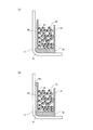
図5(a)に示すように、隔離部材40の下部に設けられた下方縁部41によって、外側周壁部42の外壁面42bと下部シェル3との間には、間隙50が形成されている。間隙50は、隔離部材40の所定の充填空間に第2ガス発生剤29等が充填されたときに、外側周壁部42の下部シェル3側への変形や変位を可能とする。そのため、当該充填によって、第2ガス発生剤29等に対して必要とされる保持力を発生させやすくなる。別法として、第2ガス発生剤等の充填に際して上記保持力を発生させることが可能であれば、上記間隙50は必ずしも必要ではなく、以て隔離部材40に下方縁部41を設ける必要もない。
更に、別法として、図5(b)に示すように、隔離部材40の外側周壁部42において、下方縁部41に加えてその上部にも外側に下方縁部41と同程度突出した上方縁部42cが設けられてもよい。このような場合も外壁面42bと下部シェル3との間に間隙50が形成され、外側周壁部42は、その中腹部の近傍で大きく変位し得、以て、上記保持力を好適に発生させることができる。また、このように下部シェル3との接触部位を、外側周壁部42の下方と上方に分散させることで、第2ガス発生剤29等の充填の際に、外側周壁部42を過度に変形等しないようにすることができる。
このように隔離部材40が、第2ガス発生剤29等と第2燃焼室28の側面及び底面との間に介在することで、第2燃焼室28において第2ガス発生剤29等の粉化と第2ガス発生剤29等による振動音の発生を好適に抑制することができる。そして、隔離部材40を含んで構成されたガス発生器1では、先ず第1点火器23が作動すると、第1伝火薬24が着火し、その後第1ガス発生剤22が燃焼する。第1燃焼室21では、アルミニウムテープ36によって、第1伝火薬24と第1ガス発生剤22との混在が防止されている。そして、第1ガス発生剤22による燃焼ガスは、フィルタ32を経てガス排出口5から外部に放出される。そして、第1点火器23に次いで第2点火器27が作動することで、第2伝火薬26が着火し、その後第2ガス発生剤29が燃焼する。第2燃焼室28では、隔離部材40によって、第2伝火薬26と第2ガス発生剤29との混在が防止されるとともに、第2ガス発生剤29等の粉化が抑制されているため、第2ガス発生剤29による燃焼ガスを設計通り生成することができる。その燃焼ガスは、貫通孔10aを通り第1燃焼室21を経てガス排出口5から外部に放出される。
<組立方法>
ここで、ガス発生器1の組立方法について、図6に基づいて説明する。当該組立方法では、隔離部材40を、第2伝火薬26及び第2ガス発生剤29を第2燃焼室28内に好適に配置するために、その配置位置を保持するリテーナとしても機能させ、ステップ1~ステップ9によってガス発生器1が組み立てられる。以下に、各ステップの詳細を説明する。先ず、ステップ1では、下部シェル3の嵌合孔3c、3dにそれぞれ第1点火器23、第2点火器27を取り付けて、両点火器を下部シェル3の底面に配置する。次に、ステップ2では、隔離部材40を下部シェル3に配置する。このとき、隔離部材40の所定空間47の開口を介して第1点火器23が所定空間47に挿入されるとともに、貫通孔48を介して第2点火器27が伝火薬充填室25に挿入される。
ここで、ガス発生器1の組立方法について、図6に基づいて説明する。当該組立方法では、隔離部材40を、第2伝火薬26及び第2ガス発生剤29を第2燃焼室28内に好適に配置するために、その配置位置を保持するリテーナとしても機能させ、ステップ1~ステップ9によってガス発生器1が組み立てられる。以下に、各ステップの詳細を説明する。先ず、ステップ1では、下部シェル3の嵌合孔3c、3dにそれぞれ第1点火器23、第2点火器27を取り付けて、両点火器を下部シェル3の底面に配置する。次に、ステップ2では、隔離部材40を下部シェル3に配置する。このとき、隔離部材40の所定空間47の開口を介して第1点火器23が所定空間47に挿入されるとともに、貫通孔48を介して第2点火器27が伝火薬充填室25に挿入される。
次に、ステップ3では、第2伝火薬26を伝火薬充填室25に充填するとともに、隔離部材40の所定の充填空間の残部に第2ガス発生剤29が充填される。この充填により、第2ガス発生剤29等は、樹脂製の隔離部材40から上述した保持力が付与された状態となり、その状態は隔離部材40の外側周壁部42や内側周壁部44によって維持される。そのため、次のステップ4で下部シェル3に分割壁10が取り付けられる際に、分割壁10と第2ガス発生剤29等との不用意な接触を好適に回避することができる。そこで、ステップ4では、下部シェル3に配置された隔離部材40の所定空間47内に、分割壁10の周壁部12を挿入するように、分割壁10を下部シェル3に取り付ける。この結果、分割壁10と下部シェル3によって第2燃焼室28が形成されるとともに、第2燃焼室28には、第2ガス発生剤29等が隔離部材40に充填された状態で収容される。
次に、ステップ5では、所定空間47内に挿入された分割壁10の周壁部12に囲まれた空間、すなわち収容空間20に第1伝火薬24が充填され、その後、ステップ6では、その収容空間20をアルミニウムテープ36で塞がれる。更に、ステップ7では、分割壁10の分割壁部13上にフィルタ32が配置され、ステップ8では、フィルタ32の中央部分に第1ガス発生剤22が充填される。そして、ステップ9では、クッション31とともに上部シェル2が下部シェル3に取り付けられる。この結果、上部シェル2と分割壁10によって第1燃焼室21が形成され、ガス発生器1の組み立てが完了する。
デュアルタイプのガス発生器1では燃焼室を上下方向に形成するために分割壁10を取り付ける必要があるが、このように隔離部材40は、第2燃焼室28で燃焼される第2ガス発生剤29等を保持する機能を有しているため、換言すると、分割壁10の周壁部12を第2燃焼室28に対して挿入するときの挿入空間を確保する機能を有しているため、分割壁10を下部シェル3に容易に取り付けることができ、組立時に第2ガス発生剤29等の破砕を回避することができる。また、隔離部材40は、樹脂材料で一体に形成されているため、特にステップ2~ステップ4の作業が容易となる。
<変形例>
ガス発生器1に適用できる隔離部材40の変形例について、図7に基づいて説明する。図7は、下部シェル3に配置された隔離部材40に関し、外側周壁部42と下部シェル3とが接触する部位の拡大図である。本変形例の隔離部材40が上記実施例の隔離部材40と異なる点は、外側周壁部42の下方に下方縁部41が設けられていない点と、外側周壁部42の内壁面側に、第2ガス発生剤29等が充填される所定の充填空間側に延出した、樹脂製の突起部42dが複数設けられている点である。この突起部42dは、充填されたガス発生剤29等から力を受けることで変形可能に、隔離部材40の本体の樹脂材料と同一の樹脂材料で形成されている。この結果、複数の突起部42dが適度に変形するように第2ガス発生剤29等を隔離部材40に充填することで、その第2ガス発生剤29等に上記の保持力が掛かった状態を好適に形成することができる。また、図7に示す隔離部材40において、図5に示す下方縁部41を設け、外側周壁部42と下部シェル3との間に間隙50を形成しても構わない。
ガス発生器1に適用できる隔離部材40の変形例について、図7に基づいて説明する。図7は、下部シェル3に配置された隔離部材40に関し、外側周壁部42と下部シェル3とが接触する部位の拡大図である。本変形例の隔離部材40が上記実施例の隔離部材40と異なる点は、外側周壁部42の下方に下方縁部41が設けられていない点と、外側周壁部42の内壁面側に、第2ガス発生剤29等が充填される所定の充填空間側に延出した、樹脂製の突起部42dが複数設けられている点である。この突起部42dは、充填されたガス発生剤29等から力を受けることで変形可能に、隔離部材40の本体の樹脂材料と同一の樹脂材料で形成されている。この結果、複数の突起部42dが適度に変形するように第2ガス発生剤29等を隔離部材40に充填することで、その第2ガス発生剤29等に上記の保持力が掛かった状態を好適に形成することができる。また、図7に示す隔離部材40において、図5に示す下方縁部41を設け、外側周壁部42と下部シェル3との間に間隙50を形成しても構わない。
また、上述の実施例のガス発生器1は、デュアルタイプのガス発生器であるが、1台の点火器を備えるシングルタイプのガス発生器においても、当該ガス発生器内に形成される燃焼室の側面及び底面と、そこに充填されるガス発生剤との直接の接触を回避するように、樹脂製の隔離部材を介在させてもよい。この場合も、当該隔離部材は、ガス発生剤の燃焼熱によって溶融する材料であるのが好ましい。
また、上述の実施例のガス発生器1では、隔離部材40が一つの部品として形成されていたが、複数の部品により隔離部材40が形成されてもよい。
1 :ガス発生器
2 :上部シェル
3 :下部シェル
4 :ハウジング
5 :ガス排出口
10 :分割壁
12 :周壁部
13 :分割壁部
14 :嵌合壁部
20 :収容空間
21 :第1燃焼室
22 :第1ガス発生剤
23 :第1点火器
24 :第1伝火薬
25 :伝火薬充填室
26 :第2伝火薬
27 :第2点火器
28 :第2燃焼室
29 :第2ガス発生剤
40 :隔離部材
41 :下方縁部
42 :外側周壁部
42c :上方縁部
42d :突起部
43 :底壁部
44 :内側周壁部
47 :所定空間
50 :間隙
2 :上部シェル
3 :下部シェル
4 :ハウジング
5 :ガス排出口
10 :分割壁
12 :周壁部
13 :分割壁部
14 :嵌合壁部
20 :収容空間
21 :第1燃焼室
22 :第1ガス発生剤
23 :第1点火器
24 :第1伝火薬
25 :伝火薬充填室
26 :第2伝火薬
27 :第2点火器
28 :第2燃焼室
29 :第2ガス発生剤
40 :隔離部材
41 :下方縁部
42 :外側周壁部
42c :上方縁部
42d :突起部
43 :底壁部
44 :内側周壁部
47 :所定空間
50 :間隙
Claims (8)
- 点火器と、
前記点火器を収容しガス排出口を形成した金属製のハウジングであって、該点火器の作動により、燃焼可能となる位置に充填された固形のガス発生剤の燃焼が行われる燃焼室を有するハウジングと、
前記ハウジングの内部において前記燃焼室に配置された前記ガス発生剤と該燃焼室の底面及び側面との間に介在し、該ガス発生剤と接触して該ガス発生剤に対して所定の保持力を付与するように所定の樹脂材料で形成された隔離壁を有する隔離部材と、
を備える、ガス発生器。 - 前記隔離部材は、前記隔離壁で前記燃焼室の底面及び側面の全てを覆うように形成されている、
請求項1に記載のガス発生器。 - 前記隔離部材は、前記所定の樹脂材料で一体に形成されている、
請求項1又は請求項2に記載のガス発生器。 - 前記燃焼室の側面の一部は、前記ハウジングの所定の内壁面により画定され、
前記隔離壁と前記ハウジングの前記所定の内壁面との間に間隙が形成されるように、前記隔離部材は、前記ハウジング内に配置される、
請求項1から請求項3の何れか1項に記載のガス発生器。 - 前記隔離壁は、前記隔離部材が前記ハウジング内に配置された状態で、前記燃焼室の内側に向かって延出した、樹脂製の複数の突起部を有し、
前記複数の突起部は、前記燃焼室に充填された前記ガス発生剤から受ける力で変形可能に形成される、
請求項1から請求項4の何れか1項に記載のガス発生器。 - 前記燃焼室に、前記ガス発生剤に加えて、固形の伝火薬が充填され、
前記隔離部材は、前記点火器の作動により前記伝火薬が燃焼されるように該伝火薬を該点火器の周囲に配置するとともに、該点火器の作動前には該伝火薬と前記ガス発生剤とが混在しないように伝火薬充填室を画定する伝火薬用隔離壁を、更に有し、
少なくとも前記伝火薬用隔離壁は、前記伝火薬の燃焼に伴って変形、破壊、燃焼、又は溶融する材料で形成されている、
請求項1から請求項5の何れか1項に記載のガス発生器。 - 前記ハウジングは、前記ガス排出口を形成した金属製の第1ハウジングと、該第1ハウジングの下方に配置される、金属製の第2ハウジングとからなり、
前記ハウジングは、その内部に、前記燃焼室を上下に分割し、上側に位置する第1燃焼室と下側に位置する第2燃焼室を形成する分割壁を含み、
前記第2ハウジングの底面に、前記第1燃焼室に充填された第1ガス発生剤を燃焼する第1点火器と、前記第2燃焼室に充填された、前記ガス発生剤である第2ガス発生剤を燃焼する前記点火器であり該第1点火器とは異なる第2点火器とが配置され、
前記分割壁は、前記第1点火器を取り囲み前記第1燃焼室内に該第1点火器を収容するように前記第2ハウジング内に延出した第1点火器収容部を形成し、
前記第2燃焼室の側面は、前記第2ハウジングの内壁面及び該第2ハウジング内に位置する前記第1点火器収容部の所定の外周壁面により画定され、
前記隔離部材は、前記第2ハウジングの内部において、前記第2燃焼室の底面及び側面と該第2燃焼室に充填された前記第2ガス発生剤との間に前記隔離壁を介在させる、
請求項1から請求項6の何れか1項に記載のガス発生器。 - ガス排出口を形成した金属製の第1ハウジングと、該第1ハウジングの下方に配置される、金属製の第2ハウジングとからなるハウジングを有し、該ハウジング内に第1点火器と該第1点火器と異なる第2点火器とを備え、それぞれに対応する第1ガス発生剤と第2ガス発生剤を燃焼させるデュアルタイプのガス発生器の組立方法であって、
前記ハウジングは、その内部に、前記燃焼室を上下に分割し、上側に位置し前記第1ガス発生剤が充填される第1燃焼室と下側に位置し前記第2ガス発生剤が充填される第2燃焼室を形成する分割壁を含み、
前記分割壁は、前記第1点火器を取り囲んで収容するように前記第2ハウジング内に延出した第1点火器収容部を形成し、
前記第2燃焼室の側面は、前記第2ハウジングの内壁面及び該第2ハウジング内に位置する前記第1点火器収容部の所定の外周壁面により画定され、
前記組立方法は、
前記第2ハウジングの底面に、前記第1点火器と前記第2点火器とを配置するステップと、
前記第2燃焼室の底面及び側面と前記第2ガス発生剤との接触を阻止し、且つ該第2ガス発生剤を充填する所定の充填空間を形成し該所定の充填空間に充填された該第2ガス発生剤に対して所定の保持力を付与するように、所定の樹脂材料で形成された隔離壁を有する隔離部材を、前記第2ハウジングの内部に配置するステップと、
前記隔離部材の前記所定の充填空間に前記第2ガス発生剤を充填し、該充填された第2ガス発生剤に前記所定の保持力が付与された状態を形成するステップと、
前記第2ハウジングに配置された前記隔離部材の前記隔離壁のうち、前記第1点火器収容部の所定の外周壁面に対応する、環状の第1点火器包囲壁によって形成される所定空間に、前記第1点火器収容部を挿入するように前記分割壁を該第2ハウジングに取り付けて、該分割壁の下方に前記第2燃焼室を形成するステップと、
前記第2ハウジングに取り付けられた前記分割壁の上方に前記第1点火器の作動により燃焼可能な位置に前記第1ガス発生剤を配置し、前記第1ハウジングで封止することで前記第1燃焼室を形成するステップと、
を含む、デュアルタイプのガス発生器の組立方法。
Priority Applications (4)
| Application Number | Priority Date | Filing Date | Title |
|---|---|---|---|
| DE112018002738.4T DE112018002738T5 (de) | 2017-05-29 | 2018-03-16 | Gasgenerator und montageverfahren für gasgenerator vom zweifachtyp |
| KR1020197035376A KR20200013670A (ko) | 2017-05-29 | 2018-03-16 | 가스 발생기 및 듀얼 타입의 가스 발생기의 조립 방법 |
| US16/617,760 US11137234B2 (en) | 2017-05-29 | 2018-03-16 | Gas generator and assembly method for dual-type gas generator |
| CN201880035412.5A CN110709287B (zh) | 2017-05-29 | 2018-03-16 | 气体发生器、以及双级型的气体发生器的组装方法 |
Applications Claiming Priority (2)
| Application Number | Priority Date | Filing Date | Title |
|---|---|---|---|
| JP2017-105942 | 2017-05-29 | ||
| JP2017105942A JP6852849B2 (ja) | 2017-05-29 | 2017-05-29 | ガス発生器、及びデュアルタイプのガス発生器の組立方法 |
Publications (1)
| Publication Number | Publication Date |
|---|---|
| WO2018220950A1 true WO2018220950A1 (ja) | 2018-12-06 |
Family
ID=64455330
Family Applications (1)
| Application Number | Title | Priority Date | Filing Date |
|---|---|---|---|
| PCT/JP2018/010504 Ceased WO2018220950A1 (ja) | 2017-05-29 | 2018-03-16 | ガス発生器、及びデュアルタイプのガス発生器の組立方法 |
Country Status (6)
| Country | Link |
|---|---|
| US (1) | US11137234B2 (ja) |
| JP (1) | JP6852849B2 (ja) |
| KR (1) | KR20200013670A (ja) |
| CN (1) | CN110709287B (ja) |
| DE (1) | DE112018002738T5 (ja) |
| WO (1) | WO2018220950A1 (ja) |
Citations (5)
| Publication number | Priority date | Publication date | Assignee | Title |
|---|---|---|---|---|
| JPS5139837A (ja) * | 1974-10-02 | 1976-04-03 | Nissan Motor | |
| JP3009569U (ja) * | 1994-09-28 | 1995-04-04 | 日本化薬株式会社 | ガス発生器 |
| WO2002051673A1 (en) * | 2000-12-26 | 2002-07-04 | Nippon Kayaku Kabushiki-Kaisha | Gas generator |
| JP2010173559A (ja) * | 2009-01-30 | 2010-08-12 | Nippon Kayaku Co Ltd | ガス発生器 |
| JP2013075656A (ja) * | 2011-09-12 | 2013-04-25 | Autoliv Development Ab | エアバッグ用インフレータ |
Family Cites Families (7)
| Publication number | Priority date | Publication date | Assignee | Title |
|---|---|---|---|---|
| JPH1159315A (ja) | 1997-08-12 | 1999-03-02 | Daicel Chem Ind Ltd | エアバッグ用ガス発生器のクッション部材 |
| US6199906B1 (en) * | 1999-08-12 | 2001-03-13 | Breed Automotive Technology, Inc. | Dual stage pyrotechnic inflator |
| DE20219898U1 (de) * | 2002-12-23 | 2003-04-30 | TRW Airbag Systems GmbH, 84544 Aschau | Gasgenerator |
| US20060267322A1 (en) * | 2005-05-26 | 2006-11-30 | Trw Vehicle Safety Systems Inc. | Apparatus for inflating an inflatable vehicle occupant restraint |
| US8444179B2 (en) * | 2006-12-06 | 2013-05-21 | Trw Vehicle Safety Systems Inc. | Dual stage air bag inflator |
| JP5638811B2 (ja) * | 2010-01-28 | 2014-12-10 | 株式会社ダイセル | ガス発生器 |
| JP5985950B2 (ja) * | 2012-10-04 | 2016-09-06 | 株式会社ダイセル | ガス発生器とその組立方法 |
-
2017
- 2017-05-29 JP JP2017105942A patent/JP6852849B2/ja active Active
-
2018
- 2018-03-16 KR KR1020197035376A patent/KR20200013670A/ko not_active Withdrawn
- 2018-03-16 US US16/617,760 patent/US11137234B2/en active Active
- 2018-03-16 WO PCT/JP2018/010504 patent/WO2018220950A1/ja not_active Ceased
- 2018-03-16 CN CN201880035412.5A patent/CN110709287B/zh active Active
- 2018-03-16 DE DE112018002738.4T patent/DE112018002738T5/de not_active Withdrawn
Patent Citations (5)
| Publication number | Priority date | Publication date | Assignee | Title |
|---|---|---|---|---|
| JPS5139837A (ja) * | 1974-10-02 | 1976-04-03 | Nissan Motor | |
| JP3009569U (ja) * | 1994-09-28 | 1995-04-04 | 日本化薬株式会社 | ガス発生器 |
| WO2002051673A1 (en) * | 2000-12-26 | 2002-07-04 | Nippon Kayaku Kabushiki-Kaisha | Gas generator |
| JP2010173559A (ja) * | 2009-01-30 | 2010-08-12 | Nippon Kayaku Co Ltd | ガス発生器 |
| JP2013075656A (ja) * | 2011-09-12 | 2013-04-25 | Autoliv Development Ab | エアバッグ用インフレータ |
Also Published As
| Publication number | Publication date |
|---|---|
| US20200173759A1 (en) | 2020-06-04 |
| CN110709287A (zh) | 2020-01-17 |
| JP6852849B2 (ja) | 2021-03-31 |
| JP2018199463A (ja) | 2018-12-20 |
| CN110709287B (zh) | 2021-12-24 |
| US11137234B2 (en) | 2021-10-05 |
| KR20200013670A (ko) | 2020-02-07 |
| DE112018002738T5 (de) | 2020-02-20 |
Similar Documents
| Publication | Publication Date | Title |
|---|---|---|
| KR102505651B1 (ko) | 가스 발생기 및 수용 용기 | |
| US8459692B2 (en) | Gas generator and method for assembling same | |
| CN110944879B (zh) | 气体发生器 | |
| JP2023059961A (ja) | ガス発生器 | |
| JP2021062814A (ja) | ガス発生器、及びガス発生器の組立方法 | |
| JP6992233B2 (ja) | ガス発生器 | |
| CN113043989B (zh) | 气体发生器 | |
| WO2018220950A1 (ja) | ガス発生器、及びデュアルタイプのガス発生器の組立方法 | |
| US11577683B2 (en) | Gas generator | |
| KR102622079B1 (ko) | 가스 발생기 | |
| JP2020199971A (ja) | ガス発生器 | |
| JP2011031763A (ja) | ガス発生器およびその製造方法 | |
| CN119255937A (zh) | 气体发生器 | |
| WO2021153368A1 (ja) | ガス発生器及びガス発生器の組立方法 | |
| WO2021261134A1 (ja) | ガス発生器 | |
| WO2020050104A1 (ja) | ガス発生器及びガス発生器用のクッション部材 | |
| US12286073B2 (en) | Filter unit for gas generator, gas generator, and method for manufacturing gas generator | |
| JP7805856B2 (ja) | 点火装置、及び、ガス発生器 | |
| JP7361660B2 (ja) | ガス発生器 | |
| WO2021149412A1 (ja) | ガス発生器 | |
| JP2008093622A (ja) | シートベルトリトラクタ用ガス発生器 |
Legal Events
| Date | Code | Title | Description |
|---|---|---|---|
| 121 | Ep: the epo has been informed by wipo that ep was designated in this application |
Ref document number: 18810053 Country of ref document: EP Kind code of ref document: A1 |
|
| ENP | Entry into the national phase |
Ref document number: 20197035376 Country of ref document: KR Kind code of ref document: A |
|
| 122 | Ep: pct application non-entry in european phase |
Ref document number: 18810053 Country of ref document: EP Kind code of ref document: A1 |