WO2018220872A1 - 扉開放装置及び冷蔵庫 - Google Patents
扉開放装置及び冷蔵庫 Download PDFInfo
- Publication number
- WO2018220872A1 WO2018220872A1 PCT/JP2017/030295 JP2017030295W WO2018220872A1 WO 2018220872 A1 WO2018220872 A1 WO 2018220872A1 JP 2017030295 W JP2017030295 W JP 2017030295W WO 2018220872 A1 WO2018220872 A1 WO 2018220872A1
- Authority
- WO
- WIPO (PCT)
- Prior art keywords
- door
- slider
- opening device
- sliding period
- refrigerator
- Prior art date
- Legal status (The legal status is an assumption and is not a legal conclusion. Google has not performed a legal analysis and makes no representation as to the accuracy of the status listed.)
- Ceased
Links
Images








Classifications
-
- F—MECHANICAL ENGINEERING; LIGHTING; HEATING; WEAPONS; BLASTING
- F25—REFRIGERATION OR COOLING; COMBINED HEATING AND REFRIGERATION SYSTEMS; HEAT PUMP SYSTEMS; MANUFACTURE OR STORAGE OF ICE; LIQUEFACTION SOLIDIFICATION OF GASES
- F25D—REFRIGERATORS; COLD ROOMS; ICE-BOXES; COOLING OR FREEZING APPARATUS NOT OTHERWISE PROVIDED FOR
- F25D23/00—General constructional features
- F25D23/02—Doors; Covers
Definitions
- the present invention relates to a door opening device for opening a door and a refrigerator equipped with the device.
- Patent Document 1 A conventional refrigerator provided with a door opening device is disclosed in Patent Document 1.
- This refrigerator includes a main body and a door.
- the main body has a heat insulating box filled with a foam heat insulating material, and has an opening surface on the front surface.
- the door is filled with foam heat insulating material, and is pivotally supported on the main body by a pivot shaft to open and close the opening surface.
- the door opening device has a plate cam arranged on the upper surface of the main body and a roller arranged on the upper surface of the door.
- the plate cam is rotated about a vertical rotation shaft by a motor, and the roller contacts the cam surface of the peripheral surface of the plate cam.
- the plate cam rotates and abuts on the door roller between the short diameter portion and the long diameter portion on the cam surface.
- the door moves and opens.
- the roller moves away from the plate cam at the long diameter portion of the cam surface, the door is manually opened. Thereby, the burden at the time of opening a door can be reduced.
- a packing that is in close contact with the main body is provided around the back of the door.
- a large motor with a large driving force is required to release the adhesion between the packing and the main body.
- the manufacturing cost of the door opening device increases. The same problem occurs when the force required to push out the door is large except when the adhesion between the packing and the main body is released.
- the present invention aims to provide a door opening device that can reduce the manufacturing cost and improve convenience, and a refrigerator equipped with the door opening device.
- the present invention provides a main body having an opening surface, a door that opens and closes the opening surface, a rotating body that is disposed on the main body and rotates about a rotation axis, and the rotating body.
- the first average acceleration obtained by averaging the accelerations of the doors during a first sliding period in which the slider slides between a predetermined intermediate point between the start point and the end point and the start point is the slide
- the child is smaller than a second average acceleration obtained by averaging the accelerations of the doors in a second sliding period in which the child slides between the intermediate point and the end point.
- the present invention provides the door opening device having the above-described configuration, wherein the door has a packing closely contacting a peripheral portion of the opening surface, and the packing and the peripheral edge when the slider reaches the vicinity of the intermediate point. It is preferable that the close contact with the part is released.
- the acceleration of the door during the second sliding period is always positive.
- the acceleration of the door during the second sliding period is constant or increased.
- an angle formed by a moving direction of the slider and a tangent to the cam surface in the first sliding period is substantially constant, and the second sliding period It is preferable that the angle increases.
- the door opening device in the door opening device having the above-described configuration, includes a self-closing mechanism that urges the door to self-close in a predetermined self-closing section, and the slider is disposed on the end point. It is preferable that the door is arranged in the self-closing section.
- the pushing direction of the door and the moving direction of the slider are orthogonal to each other.
- the door is formed integrally with the storage case and slides back and forth, and the cam surface is disposed below the storage case.
- the refrigerator of the present invention is characterized by including the door opening device having the above-described configuration.
- the first average acceleration obtained by averaging the accelerations of the doors during the first sliding period in which the slider slides between the start point and the predetermined intermediate point is calculated as follows. It is smaller than the 2nd average acceleration which averaged the acceleration of the door of the 2nd sliding period which slides between. As a result, the average acceleration (first average acceleration) of the door from the starting point to the middle point of the slider becomes small, so that it is not necessary to use a large motor with a large driving force. On the other hand, since the average acceleration (second average acceleration) of the door after the slider has passed the intermediate point is larger than the first average acceleration, the door can be pushed out vigorously, and the range for manually opening the door is reduced. can do. Therefore, the manufacturing cost of the door opening device and the refrigerator including the door opening device can be reduced, and convenience can be improved.
- the front view which shows the refrigerator of 1st Embodiment of this invention The top view which shows the closed state of the door of the refrigerator of 1st Embodiment of this invention.
- the top view which shows the state which the slider at the time of operation
- the top view which shows the positional relationship of a guide part and a slider when the slider of the door opening apparatus of the refrigerator of 1st Embodiment of this invention reaches the starting point.
- the top view which shows the positional relationship of the guide part and slider in the 2nd sliding period of the door opener of the refrigerator of 1st Embodiment of this invention.
- the top view for demonstrating the speed of the door of the 1st sliding period of the door opener of the refrigerator of 1st Embodiment of this invention The top view for demonstrating the speed of the door of the 2nd sliding period of the door opener of the refrigerator of 1st Embodiment of this invention.
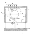
- Plan sectional drawing which shows the state which the slider reached
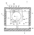
- Plan sectional drawing which shows the state of the 1st sliding period of the refrigerator of 5th Embodiment of this invention.
- Plan sectional drawing which shows the state of the 2nd sliding period of the refrigerator of 5th Embodiment of this invention.
- Plan sectional drawing which shows the state which the slider at the time of operation
- the surface (opening surfaces 3 a, 5 c, 7 c) on which the doors 4 a, 4 b, 6, 8 are closed is referred to as “front side”, and the doors 4 a, 4 b, The opposite side of 6 and 8 is the “back side”.
- the direction from the “back side” to the “front side” is “front”, and the direction from the “front side” to the “back side” is “back”.
- the right side surface is the “right side surface” and the left side surface is the “left side surface”.
- the direction from the “left side” to the “right side” is defined as “right direction”, and the direction from the “right side” to the “left side” is defined as “left direction”.
- the direction toward the floor surface FL in the room is “downward” and the direction away from the floor surface FL is “upward”.
- Drawing 1 is a front view showing refrigerator 1 of a 1st embodiment.
- the refrigerator 1 is installed on the floor surface FL in the room, and a refrigerator compartment 3, a freezer compartment 5, and a vegetable compartment 7 are formed in this order from the top of the main body 2 made of a heat insulating box.
- a door 4a and a door 4b are arranged side by side on the front side of the refrigerator compartment 3.
- the door 4a and the door 4b are pivotally supported by vertical pivot shafts 4c (see FIG. 2) and pivot shafts 4d (see FIG. 2) arranged on both sides of the main body 2, respectively, and are opened at the front of the refrigerator compartment 3.
- An opening surface 5c (not shown) on the front surface of the freezer compartment 5 is opened and closed by a sliding door 6 (drawing door).
- An opening surface 7c (not shown) on the front surface of the vegetable compartment 7 is opened and closed by a sliding door 8 (drawing door).
- the packing 80 (refer FIG. 2) which prevents a cold-air leak is provided in the peripheral part of the back surface of the door 4a, 4b, 6, 8.
- the packing 80 is made of resin, and the packing 80 is provided with a magnet (not shown) that is attracted to the front surface of the main body 2. That is, the doors 4a, 4b, 6, and 8 have packings 80 that are in close contact with the peripheral portions of the opening surfaces 3a, 5c, and 7c.
- FIG. 2 shows a top view of the refrigerator 1.
- a door opening device 50 that opens the door 4a is provided on the upper surfaces of the main body 2 and the door 4a.
- a door opening device 50 that opens the door 4b is provided on the upper surface of the main body 2 and the door 4b.
- the door opening device 50 includes a drive unit 58 and a guide unit 60.
- the drive unit 58 is installed on a support member 51 attached to the upper surface of the main body unit 2.
- the drive unit 58 includes a motor 52, a worm 53, a worm wheel 54, a reduction gear 55, and a reduction gear 56 (rotary body).
- the worm 53 is attached to a shaft (not shown) of the motor 52 and meshes with the worm wheel 54.
- the reduction gear 55 is attached concentrically with the worm wheel 54.
- the reduction gear 56 meshes with the reduction gear 55.
- the reduction gear 56 is provided with a slider 59 protruding downward.
- the rotation shaft 56a (see FIG. 7) of the reduction gear 56 forms the rotation center of the slider 59, and is arranged behind the pivot shaft 4c and the pivot shaft 4d.
- the guide part 60 is provided on the upper surface of the door 4a and the door 4b, and has a curved cam surface 60a for slidingly guiding the slider 59.
- the slider 59 slides between the start point Ps and the end point Pe on the cam surface 60a to open the door 4a and the door 4b.
- a predetermined intermediate point Pc is disposed between the start point Ps and the end point Pe on the cam surface 60a.
- the cam surface 60a between the start point Ps and the intermediate point Pc and the cam surface 60a between the intermediate point Pc and the end point Pe are smoothly connected.
- the rotation direction B1 of the slider 59 is the direction away from the pivot shaft 4c in the forward direction (counterclockwise in the figure).
- the slider 59 rotates by a predetermined angle (for example, about 45 °) and contacts the starting point Ps on the cam surface 60a as shown in FIG. 3, the sliding between the slider 59 and the cam surface 60a starts. Is done. For this reason, the idle period during which the slider 59 idles is provided from the closed state of the door 4a until it abuts on the starting point Ps. Due to the idling period, the rotation and torque of the motor 52 can be stabilized before the start of the opening operation with a large load when the door 4a is opened by the suction force of the packing 80.
- a predetermined angle for example, about 45 °
- the starting point Ps is arranged ahead of the moving direction of the slider 59 with respect to the straight line connecting the pivot shaft 4c and the rotation shaft 56a of the reduction gear 56 (see FIG. 7).
- the guide part 60 can be reliably arrange
- FIG. 4 shows a top view of the refrigerator 1 during the first sliding period T1 in which the slider 59 slides between the start point Ps and the intermediate point Pc.
- the slider 59 further rotates from the starting point Ps on the cam surface 60a and reaches the vicinity of the intermediate point Pc, the close contact between the packing 80 and the peripheral portion of the opening surface 3a of the main body 2 is released. Note that, as long as the slider 59 passes through the intermediate point Pc, the close contact between the packing 80 and the peripheral edge portion of the opening surface 3a of the main body 2 may be released as long as it is in the vicinity of the intermediate point Pc.
- FIG. 5 shows a top view of the refrigerator 1 during the second sliding period T2 in which the slider 59 slides between the intermediate point Pc and the end point Pe.
- the door 4a is opened.
- the slider 59 reaches the end point Pe on the cam surface 60a and leaves the cam surface 60a.
- the door 4a is further opened by the urging force when the slider 59 is separated from the cam surface 60a. Therefore, the burden at the time of opening the door 4a can be reduced.
- the door 4b is opened in the same manner as the door 4a when the slider 59 of the right door opening device 50 rotates in the rotation direction B2 (clockwise in FIG. 2).
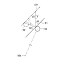
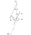
- FIG. 7 to 9 are plan views for explaining the angle ⁇ 2 formed by the moving direction LD of the slider 59 and the tangent line S1 of the cam surface 60a.
- FIG. 7 shows a state in which the slider 59 is arranged on the starting point Ps.
- FIG. 8 shows a state during the second sliding period T2.
- FIG. 9 shows a state in which the slider 59 is arranged on the end point Pe.
- Arrow P1 indicates the pushing direction of the door 4a.
- the rotation angle of the slider 59 is ⁇ r, and the opening angle of the door 4a (the angle formed by the front surface of the door 4a and the opening surface 3a) is ⁇ d.
- an angle formed between the pushing direction of the door 4a and the tangent line S1 of the cam surface 60a of the slider 59 is defined as ⁇ 1, and an angle ⁇ 2 formed between the moving direction LD of the slider 59 and the tangent line S1 of the cam surface 60a.
- the angles ⁇ 1 and ⁇ 2 are smaller than 90 °.
- the sum of the rotation angle ⁇ r, the angle ⁇ 1, the angle ⁇ 2, and the opening angle ⁇ d is 180 °.
- the angle ⁇ 1 decreases and the angle ⁇ 2 increases.
- FIG. 10 is a plan view for explaining the speed (opening speed) of the door 4a in the first sliding period T1
- FIG. 11 is for explaining the speed (opening speed) of the door 4a in the second sliding period T2.
- FIG. 10 Note that the alternate long and short dash line 59 'and alternate long and short dash line S11 indicate the positions of the slider 59 and the tangent S1, respectively, after a predetermined minute time has elapsed.
- the angle ⁇ 1 is equal to the angle formed by the tangent S1 and the speed vector V of the door 4a, and the angle ⁇ 2 is equal to the angle formed by the tangent S1 and the speed vector L of the slider 59. If the magnitudes of the velocity vectors V and L are the speeds
- the angle ⁇ 1 is smaller and the angle ⁇ 2 is larger than in the first sliding period T1.
- of the second sliding period T2 becomes larger than the speed
- may be referred to as the speed of the door 4a (opening speed).
- FIG. 12 is a diagram showing changes in the speed
- the left vertical axis indicates the speed
- the vertical axis on the right indicates angles ⁇ 1 and ⁇ 2 (unit: °).
- the horizontal axis indicates the movement distance (open distance) of the door 4a, and the closed state of the door 4a is set to zero.
- Solid lines K1 and K2 indicate changes in the angles ⁇ 1 and ⁇ 2, respectively, and a broken line K3 indicates a change in the speed
- the position of the slider 59 and the cam surface 60a of the guide 60 are set so that the point where the movement distance of the door 4a is 0 is the start point Ps and the point where the movement distance is 67 is the end point Pe.
- the slider 59 reaches the vicinity of the intermediate point Pc.
- the angle ⁇ 1 decreases in the first sliding period T1 and the second sliding period T2.
- the angle ⁇ 2 is substantially constant during the first sliding period T1, and increases as the moving distance of the door 4a increases during the second sliding period T2.
- increases during the first sliding period T1 and the second sliding period T2, and becomes maximum when the slider 59 reaches the end point Pe (at the end of the second sliding period T2). Yes. That is, the speed of the door 4a is maximum when the slider 59 reaches the end point Pe.
- in the first sliding period T1 is the average slope of the graph showing the change of the speed
- the average acceleration A1 obtained by averaging the acceleration of the door 4a during the first sliding period T1 is smaller than the average acceleration A2 obtained by averaging the acceleration of the door 4a during the second sliding period T2.
- the average acceleration A1 is the average acceleration immediately after the slider 59 hits the cam surface 60a at the starting point Ps.
- the door 4a has a packing 80 that is in close contact with the peripheral edge of the opening surface 3a. Further, since the air pressure in the refrigerator compartment 3 decreases as the refrigerator compartment 3 is cooled, the closed door 4 a is in a state of being adsorbed by the opening surface 3 a on the front surface of the refrigerator compartment 3. Therefore, when opening the door 4a in the closed state, first, in order to release this adsorbed state, a pressing force sufficient to overcome the adhesion force of the packing 80 and the negative pressure from the refrigerator compartment 3 is required.
- the torque generated by the motor 52 is used for the pressing force of the door 4a without spending acceleration of the door 4a. Can do.
- the load of the motor 52 can be prevented from becoming excessively large in the first sliding period T1, and the closed state of the door 4a can be reliably released without using a large motor having a large driving force.
- the tight contact between the packing 80 and the peripheral portion of the opening surface 3a is released.
- the state in which the tight contact between the packing 80 and the peripheral portion of the opening surface 3a is released is a state in which a gap is generated between at least a part of the packing 80 and the peripheral portion of the opening surface 3a. In this state, at least one side of the peripheral edge of the opening surface 3 a is separated from the packing 80.
- the negative pressure from the refrigerator compartment 3 that adsorbs the door 4a is eliminated. Further, in a state where the packing 80 is separated from at least one side of the peripheral edge of the opening surface 3a, the packing 80 facing two sides adjacent to the separated side can be easily pulled from the end on the side of the packing 80 that has already been separated. It can be peeled off. For this reason, a large pressing force is not required to separate the entire packing 80 from the peripheral edge of the opening surface 3a.
- the average acceleration A2 of the door 4a in the second sliding period T2 in which the slider 59 slides between the intermediate point Pc and the end point Pe is set to be equal to the average acceleration A2 of the door 4a in the first sliding period T1. It is larger than the average acceleration A1.
- the average acceleration of the door 4a is reduced in order to spend the torque generated by the motor 52 on the pressing force of the door 4a. For this reason, the opening speed of the door 4a does not increase in the first sliding period T1. Therefore, in the second sliding period T2, the opening speed of the door 4a is increased by increasing the average acceleration of the door 4a than in the first sliding period T1, and the door when the slider 59 reaches the end point Pe. The opening speed of 4a can be increased.
- the first average acceleration A1 obtained by averaging the accelerations of the doors 4a and 4b in the first sliding period T1 is the second average acceleration A2 obtained by averaging the accelerations of the doors 4a and 4b in the second sliding period T2.
- the average acceleration A1 (first average acceleration) of the doors 4a and 4b from the start point Ps to the intermediate point Pc of the slider 59 becomes small, so there is no need to use a large motor with a large driving force.
- the average acceleration A2 (second average acceleration) of the doors 4a and 4b after the slider 59 passes the intermediate point Pc is larger than the average acceleration A1, the doors 4a and 4b can be pushed out vigorously.
- the range for manually opening the doors 4a and 4b can be reduced. Therefore, the manufacturing cost of the door opening device 50 and the refrigerator 1 including the door opening device 50 can be reduced and convenience can be improved.
- the doors 4a and 4b have a packing 80 that is in close contact with the peripheral portion of the opening surface 3a, and when the slider 59 reaches near the intermediate point Pc, the close contact between the packing 80 and the peripheral portion of the opening surface 3a is achieved. Canceled. Thereby, the acceleration of the doors 4a and 4b can be increased immediately before or after the close contact between the packing 80 and the peripheral edge of the opening surface 3a. Therefore, the opening speed of the doors 4a and 4b can be increased while reducing the burden on the motor 52 of the door opening device 50.
- the acceleration of the doors 4a and 4b in the second sliding period T2 is always positive.
- the opening speed of the doors 4a and 4b continues to increase during the second sliding period T2, so that the slider 59 does not move away from the cam surface 60a. Therefore, the doors 4a and 4b can be accelerated using the entire region of the second sliding period T2, and the speed of the doors 4a and 4b can be reliably increased when the slider 59 reaches the end point Pe. .
- the doors 4a and 4b are surely pushed out vigorously.
- the acceleration of the doors 4a and 4b during the second sliding period T2 increases. Accordingly, the speed of the door 4a can be further increased when the slider 59 reaches the end point Pe. Thereby, the doors 4a and 4b are pushed out more reliably and vigorously.
- the pushing direction (arrow P1) of the doors 4a and 4b and the moving direction LD of the slider 59 may be orthogonal to each other.
- a straight line connecting the slider 59 and the rotation shaft 56a and a straight line connecting the slider 59 and the pivot shaft 4c slide. It is orthogonal at the child 59.
- a straight line connecting the slider 59 and the pivot shaft 4 c becomes a tangent to the rotation path arc of the slider 59.
- the acceleration of the doors 4a and 4b can be further increased, the moving distance to the front of the doors 4a and 4b can be increased, and the range for manually opening the doors 4a and 4b can be reduced. be able to.
- the cam surface 60a between the start point Ps and the intermediate point Pc and the cam surface 60a between the intermediate point Pc and the end point Pe are smoothly connected. Thereby, the slider 59 can slide smoothly on the cam surface 60a. Therefore, the door opening device 50 can smoothly push out the doors 4a and 4b.
- the door opening device 50 may be disposed on the lower surface of the main body 2 and the lower surfaces of the doors 4a and 4b. .
- FIG. 13 has shown the left view of the refrigerator 1 of 2nd Embodiment.
- the same reference numerals are given to the same parts as those in the first embodiment shown in FIGS.
- This embodiment is different from the first embodiment in that a self-closing mechanism is provided.
- Other parts are the same as those in the first embodiment.
- the main body 2 has a hinge pin 20 (see FIG. 14) that forms a pivot shaft 4c, and an upper angle 21 and a lower angle 22 that support the upper and lower sides of the door 4a are projected forward.
- a hinge pin 20 see FIG. 14
- an upper angle 21 and a lower angle 22 that support the upper and lower sides of the door 4a are projected forward.
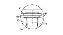
- FIG. 14 shows a detailed view of part A of FIG.
- the upper angle 21 is made of a metal plate, and a metal hinge pin 20 extends downward and is erected.
- a shaft hole 26 that pivotally supports the hinge pin 20 is provided in the door 4a.
- a leaf spring 19 is sandwiched between the seating surface of the hinge pin 20 and the upper surface of the door 4a, and the door 4a is urged downward by the leaf spring 19.
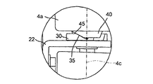
- FIG. 15 shows a detailed view of part B of FIG.
- the lower angle 22 is made of a metal plate, and a metal hinge pin 20 extends upward and is erected.
- a lower hinge member 30 is attached on the lower angle 22.
- An upper hinge member 40 that is in sliding contact with the lower hinge member 30 is attached to the lower surface of the door 4a.
- the upper hinge member 40 is provided with a shaft hole 43 (see FIG. 17) for pivotally supporting the hinge pin 20.
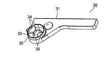
- FIG. 16 shows a perspective view of the lower hinge member 30 as viewed from above.
- the lower hinge member 30 is formed of a resin molded product, and a through hole 33 is provided at one end of a base portion 31 that is screwed to the lower angle 22 (see FIG. 15).
- the hinge pin 20 erected on the lower angle 22 is inserted into the through hole 33.
- a fitting portion 32 having a cylindrical inner wall concentric with the hinge pin 20 is provided around the through hole 33.
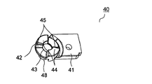
- FIG. 17 is a perspective view of the upper hinge member 40 as viewed from below.
- the upper hinge member 40 is formed of a resin molded product, and a cylindrical portion 48 protrudes from one end of a base portion 41 that is screwed to the door 4a.
- the cylindrical portion 48 is embedded in the door 4a, and a shaft hole 43 is formed therein.
- the hinge pin 20 inserted through the through hole 33 (see FIG. 16) of the lower hinge member 30 is fitted into the shaft hole 43 and pivotally supports the hinge pin 20.
- a convex portion 42 that fits into the fitting portion 32 of the lower hinge member 30 is formed.
- a plurality of flat portions 44 made of a horizontal plane are provided point-symmetrically within a predetermined angle range.
- a plurality of slopes 45 inclined upward with respect to the flat portion 44 are provided in a predetermined angle range continuous to the flat portion 44 in a point-symmetric manner.
- the slope 35 (see FIG. 16) of the lower hinge member 30 and the slope 45 (see FIG. 17) of the upper hinge member 40 start to slide.
- the door 4a rotates in the closing direction while being lowered by the urging force of its own weight, and self-closes.
- the slopes 35 and 45 constitute a self-closing mechanism portion that self-closes the door 4a by its own weight in a self-closing section from the sliding start position to the closing position of the door 4a.
- the door 4a can be closed more reliably by the urging force of the leaf spring 19.
- the self-closing section the door 4a rotates while being accelerated by its own weight.
- the slope 45 (see FIG. 17) of the upper hinge member 40 is arranged on the slope 35 (see FIG. 16) of the lower hinge member 30.
- the door 4a is arranged in the self-closing section.
- the door 4b is self-closed by the self-closing mechanism part similarly to the door 4a.
- the doors 4a and 4b do not have a sufficient opening speed when the slider 59 is disposed on the end point Pe, the range of manually opening the doors 4a and 4b may increase, or the door 4a. 4b may be closed by the self-closing mechanism.
- the doors 4a and 4b can be pushed out vigorously by the door opening device 50 as in the first embodiment. That is, the door opening device 50 allows the doors 4a and 4b to have a sufficient opening speed. For this reason, at the time of normal use, the doors 4a and 4b can be vigorously opened to get over the self-closing mechanism, so that the opened state of the doors 4a and 4b can be maintained, and the convenience of the refrigerator 1 is improved. Can do. On the other hand, the doors 4a and 4b can be reliably closed by the self-closing mechanism even when there is an obstacle in the vicinity of the front of the doors 4a and 4b.
- the doors 4a and 4b when there is no obstacle in the vicinity of the front of the doors 4a and 4b, the doors 4a and 4b are opened with force and the doors 4a and 4b are manually opened as in the first embodiment. Can be small.
- the doors 4a and 4b are self-closed by the self-closing mechanism formed by the slopes 35 and 45, and the doors 4a and 4b are arranged in the self-closing section when the slider 59 is arranged on the end point Pe.
- the doors 4a and 4b can be reliably closed by the self-closing mechanism. Therefore, it is possible to prevent cold air leakage from the refrigerator compartment 3 due to an incompletely closed state of the doors 4a and 4b.
- FIG. 18 is a diagram illustrating changes in the speed
- the speed
- the same reference numerals are given to the same parts as those in the first embodiment shown in FIGS.
- This embodiment is different from the first embodiment in the configuration of the cam surface 60a. Other parts are the same as those in the first embodiment.
- the angle ⁇ 1 gradually decreases and the angle ⁇ 2 gradually increases from the start of the first sliding period T1 to the end of the second sliding period T2.
- increases as the slider 59 moves from the start point Ps to the end point Pe, and becomes maximum when the slider 59 reaches the end point Pe (at the end of the second sliding period T2). ing. That is, as in the first embodiment, when the slider 59 reaches the end point Pe, the speed of the door 4a is maximized.
- the average acceleration A1 obtained by averaging the acceleration of the door 4a during the first sliding period T1 is smaller than the average acceleration A2 obtained by averaging the acceleration of the door 4a during the second sliding period T2. ing.
- the load of the motor 52 is not excessively increased in either the first sliding period T1 or the second sliding period T2, and the second sliding period starts from the first sliding period T1.
- the load on the motor 52 can be made uniform over the period T2.
- the same effect as that of the first embodiment can be obtained.
- the angle ⁇ 2 is gradually increased from the start of the first sliding period T1
- the speed of the doors 4a and 4b is gradually increased by the end of the first sliding period T1. This eliminates the need to rapidly increase the acceleration of the doors 4a and 4b at the start of the second sliding period T2. Therefore, for example, when the doors 4a and 4b are relatively small and light and the pressing force against the packing 80 and the negative pressure in the cabinet does not need to be large, the doors 4a and 4b Manual opening range can be reduced.
- FIG. 19 is a diagram illustrating a change in the speed
- the speed
- the same reference numerals are given to the same parts as those in the first embodiment shown in FIGS. This embodiment is different from the first embodiment in the configuration of the cam surface 60a. Other parts are the same as those in the first embodiment.
- the angle ⁇ 1 decreases substantially linearly in the first sliding period T1 and rapidly decreases in the second sliding period T2.
- the angle ⁇ 2 is substantially constant during the first sliding period T1, and rapidly increases during the second sliding period T2.
- is substantially constant during the first sliding period T1, increases substantially linearly during the second sliding period T2, and when the slider 59 reaches the end point Pe (second sliding period). (At the end of the period T2). That is, as in the first embodiment, when the slider 59 reaches the end point Pe, the speed of the door 4a is maximized.
- the average acceleration A1 obtained by averaging the acceleration of the door 4a during the first sliding period T1 is smaller than the average acceleration A2 obtained by averaging the acceleration of the door 4a during the second sliding period T2. ing.
- the speed of the door 4a is substantially constant during the first sliding period T1
- the acceleration of the door 4a is substantially constant during the second sliding period T2.
- the load of the motor 52 is not excessively increased in either the first sliding period T1 or the second sliding period T2, and the second sliding period starts from the first sliding period T1.
- the load on the motor 52 can be made uniform over the period T2.
- the angle ⁇ 2 formed by the moving direction LD of the slider 59 in the first sliding period T1 and the tangent S1 of the cam surface 60a is substantially constant, and the angle of the second sliding period T2 ⁇ 2 increases.
- is substantially constant, that is, the acceleration of the doors 4a and 4b is substantially zero.
- The increase, that is, the acceleration of the doors 4a and 4b is made substantially constant.
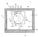
- FIG. 20 shows a plan sectional view of the freezer compartment 5 of the refrigerator 1 of the fifth embodiment.
- the same reference numerals are given to the same parts as those in the first embodiment shown in FIGS.
- This embodiment is different from the first embodiment in that the door 6 of the freezer compartment 5 is opened by the door opening device 50.
- Other parts are the same as those in the first embodiment.
- the door 6 of the freezer compartment 5 is formed integrally with the storage case 5 b and slides back and forth by the moving mechanism 70.
- the moving mechanism 70 includes a rail 71, rollers (not shown), and a frame (not shown).
- the rails 71 are attached to both side walls of the freezer compartment 5 and formed to extend in the front-rear direction.
- the rollers are arranged in front of the rails, and have a horizontal rotation shaft and are supported on both side walls of the freezer compartment 5.
- the frame is made of metal and extends rearward from the left and right ends of the door 6.
- the storage case 5b is placed on both frames.
- the door 6 can slide back and forth as the frame slides on the rail. At this time, the roller rolls on the lower surface of the frame.
- an inclined surface is formed at the front end of the lower surface of the frame so as to incline downward as it goes backward.
- rolling on the inclined surface of the roller is started.
- the door 6 slides in the closing direction while being lowered by the urging force of its own weight, and self-closes.
- the inclined surface constitutes a self-closing mechanism portion that self-closes the door 6 by its own weight in a self-closing section from the roller rolling start position to the door 6 closing position. In the self-closing section, the door 6 slides while being accelerated by its own weight.
- a door opening device 50 for opening the door 6 is provided below the storage case 5b.
- the drive unit 58 is installed on a support member 51 attached to the bottom wall of the freezer compartment 5.
- the guide unit 60 is attached to the door 6.
- the slider 59 is rotated at a constant speed by the drive unit 58. Accordingly, as shown in FIGS. 21 to 23, the slider 59 slides on the cam surface 60a of the door 6, and the slider 59 moves away from the cam surface 60a at the end point Pe and the door 6 slides forward. Open. At this time, the rotation direction B1 of the slider 59 is the direction away from the left side wall of the freezer compartment 5 in the forward direction (counterclockwise in the figure). Also, as shown in FIG. 22, when the slider 59 reaches the vicinity of the intermediate point Pc, the close contact between the packing 80 and the peripheral portion of the opening surface 5c of the main body 2 is released.
- the angle ⁇ 1 of the present embodiment is the opening angle with the angle ⁇ 1 of the first embodiment. This corresponds to the sum of ⁇ d. Further, since the opening angle ⁇ d is about 5 ° and is small, the case of the drawer type door 6 of the present embodiment can be considered in the same manner as the case of the rotary type doors 4a and 4b of the first embodiment.
- the door opening device 50 may be arranged in the vegetable compartment 7 and the door 8 may be opened by the door opening device 50.
- the refrigerator 1 may be provided with the self-closing mechanism part similar to the self-closing mechanism part of 2nd Embodiment.
- door opening device 50 of the first to fifth embodiments may be used for devices other than the refrigerator 1.
- the present invention can be used for a door opening device that opens a door and a refrigerator equipped with the door opening device.
Landscapes
- Engineering & Computer Science (AREA)
- Chemical & Material Sciences (AREA)
- Combustion & Propulsion (AREA)
- Physics & Mathematics (AREA)
- Mechanical Engineering (AREA)
- Thermal Sciences (AREA)
- General Engineering & Computer Science (AREA)
- Refrigerator Housings (AREA)
Abstract
製造コストを削減して利便性を向上できる扉開放装置及びこれを備えた冷蔵庫を提供する。開口面3aを有する本体部2と、開口面3aを開閉する扉4aと、本体部2に配して回転軸を中心に回転する回転体56と、回転体56を駆動するモータ52と、回転体56に配される摺動子59と、扉4aに配されるとともに摺動子59を案内するカム面60aとを備え、摺動子59がカム面60a上の始点Psと終点Peとの間を摺動して扉4aを開く扉開放装置50において、摺動子59が始点Psと終点Peとの間の所定の中間点Pcと始点Psとの間を摺動する第1摺動期間T1の扉4aの加速度を平均した第1平均加速度A1は、摺動子59が中間点Pcと終点Peとの間を摺動する第2摺動期間T2の扉4aの加速度を平均した第2平均加速度A2よりも小さい。
Description
本発明は扉を開く扉開放装置及びそれを備えた冷蔵庫に関する。
扉開放装置を備えた従来の冷蔵庫は特許文献1に開示されている。この冷蔵庫は本体部及び扉を備える。本体部は発泡断熱材を充填した断熱箱体を有し、前面に開口面を有する。扉は発泡断熱材を充填され、本体部に枢支軸で枢支して開口面を開閉する。
扉開放装置は本体部の上面に配される板カムと扉の上面に配されるコロとを備えている。板カムはモータによって垂直な回転軸を中心に回転し、コロは板カムの周面のカム面に当接する。
上記構成の冷蔵庫において、所定の操作が行われると板カムが回転し、カム面上の短径部と長径部との間で扉のコロに当接する。カム面上のコロとの当接位置と板カムの回転中心との距離の増加に伴って扉が移動して開かれる。カム面の長径部でコロが板カムから離れると、扉が手動で開かれる。これにより、扉を開く際の負担を軽減することができる。
一般的に冷蔵庫では、冷気漏れを防止するために例えば扉の背面の周部に本体部に密着するパッキンが設けられる。上記従来の扉開放装置の扉にパッキンを設けた場合、扉を勢いよく押し出すために扉の加速度を大きくすると、パッキンと本体部との密着を解除するために駆動力の大きい大型のモータが必要になり、扉開放装置の製造コストが増大する問題があった。また、パッキンと本体部との密着を解除する場合以外で扉を押し出すのに必要な力が大きい場合にも同様な問題があった。一方、扉の加速度を小さくすると小型のモータを使用して扉開放装置の製造コストを削減できるが、扉を勢いよく押し出すことができない。このため、扉を手動で開く範囲が大きくなり、利便性が悪い問題があった。
本発明は、製造コストを削減して利便性を向上できる扉開放装置及びそれを備えた冷蔵庫を提供することを目的とする。
上記目的を達成するために本発明は、開口面を有する本体部と、前記開口面を開閉する扉と、前記本体部に配して回転軸を中心に回転する回転体と、前記回転体を駆動するモータと、前記回転体に配される摺動子と、前記扉に配されるとともに前記摺動子を案内するカム面とを備え、前記摺動子が前記カム面上の始点と終点との間を摺動して前記扉を開く扉開放装置において、
前記摺動子が前記始点と前記終点との間の所定の中間点と前記始点との間を摺動する第1摺動期間の前記扉の加速度を平均した第1平均加速度は、前記摺動子が前記中間点と前記終点との間を摺動する第2摺動期間の前記扉の加速度を平均した第2平均加速度よりも小さいことを特徴としている。
前記摺動子が前記始点と前記終点との間の所定の中間点と前記始点との間を摺動する第1摺動期間の前記扉の加速度を平均した第1平均加速度は、前記摺動子が前記中間点と前記終点との間を摺動する第2摺動期間の前記扉の加速度を平均した第2平均加速度よりも小さいことを特徴としている。
また本発明は、上記構成の扉開放装置において、前記扉は前記開口面の周縁部に密着するパッキンを有し、前記摺動子が前記中間点の近傍に到達した際に前記パッキンと前記周縁部との密着が解除されることが好ましい。
また本発明は、上記構成の扉開放装置において、前記第2摺動期間の前記扉の加速度が常に正であることが好ましい。
また本発明は、上記構成の扉開放装置において、前記第2摺動期間の前記扉の加速度が一定または増加することが好ましい。
また本発明は、上記構成の扉開放装置において、前記第1摺動期間の前記摺動子の移動方向と前記カム面の接線との成す角度が略一定であるとともに、前記第2摺動期間の前記角度が増加することが好ましい。
また本発明は、上記構成の扉開放装置において、所定の自閉区間で前記扉を付勢して自閉させる自閉機構部を備え、前記摺動子が前記終点上に配された際に前記扉が前記自閉区間内に配されることが好ましい。
また本発明は、上記構成の扉開放装置において、前記摺動子が前記終点上に配された際に前記扉の押出方向と前記摺動子の移動方向とが直交することが好ましい。
また本発明は、上記構成の扉開放装置において、前記扉は収納ケースと一体に形成して前後にスライドし、前記カム面は前記収納ケースの下方に配置されることが好ましい。
また本発明の冷蔵庫は上記構成の扉開放装置を備えることを特徴としている。
本発明によると、摺動子が始点と所定の中間点との間を摺動する第1摺動期間の扉の加速度を平均した第1平均加速度は、摺動子が中間点と終点との間を摺動する第2摺動期間の扉の加速度を平均した第2平均加速度よりも小さい。これにより、摺動子が始点から中間点に至るまでの扉の平均加速度(第1平均加速度)が小さくなるため、駆動力の大きい大型のモータを用いる必要がなくなる。一方、摺動子が中間点を通過した後の扉の平均加速度(第2平均加速度)は第1平均加速度よりも大きいため、扉を勢いよく押し出すことができ、扉を手動で開く範囲を小さくすることができる。したがって、扉開放装置及びそれを備えた冷蔵庫の製造コストを削減して利便性を向上させることができる。
以下に図面を参照して本発明の例示的な実施形態を説明する。なお、本明細書では、冷蔵庫1において、扉4a、4b、6、8が閉じる面(開口面3a、5c、7c)側を「前面側」とし、本体部2に対して扉4a、4b、6、8の反対側を「背面側」とする。「背面側」から「前面側」に向かう方向を「前方」とするとともに「前面側」から「背面側」に向かう方向を「後方」とする。
また、「前面」側から冷蔵庫1を見て右側の側面を「右側面」とするとともに左側の側面を「左側面」とする。「左側面」側から「右側面」側に向かう方向を「右方向」とするとともに「右側面」側から「左側面」側に向かう方向を「左方向」とする。
また、冷蔵庫1において、室内の床面FLに向かう方向を「下方向」とするとともに床面FLから離れる方向を「上方向」とする。
<第1実施形態>
以下に図面を参照して本発明の実施形態を説明する。図1は第1実施形態の冷蔵庫1を示す正面図である。冷蔵庫1は室内の床面FL上に設置され、断熱箱体から成る本体部2の上方から順に冷蔵室3、冷凍室5、野菜室7が形成される。
以下に図面を参照して本発明の実施形態を説明する。図1は第1実施形態の冷蔵庫1を示す正面図である。冷蔵庫1は室内の床面FL上に設置され、断熱箱体から成る本体部2の上方から順に冷蔵室3、冷凍室5、野菜室7が形成される。
冷蔵室3の前面には扉4a及び扉4bが左右に並設される。扉4a及び扉4bは本体部2の両側部に配される鉛直な枢支軸4c(図2参照)及び枢支軸4d(図2参照)でそれぞれ枢支され、冷蔵室3の前面の開口面3a(図2参照)を開閉する。冷凍室5の前面の開口面5c(不図示)はスライド式の扉6(引出式扉)により開閉される。野菜室7の前面の開口面7c(不図示)はスライド式の扉8(引出式扉)により開閉される。
扉4a、4b、6、8の背面の周部には冷気漏れを防止するパッキン80(図2参照)が設けられる。パッキン80は樹脂により形成され、パッキン80には本体部2の前面に吸着するマグネット(不図示)が設けられる。すなわち、扉4a、4b、6、8は開口面3a、5c、7cの周縁部に密着するパッキン80を有する。
図2は冷蔵庫1の上面図を示している。本体部2及び扉4aの上面には扉4aを開く扉開放装置50が設けられる。同様に、本体部2及び扉4bの上面には扉4bを開く扉開放装置50が設けられる。扉開放装置50は駆動部58及び案内部60を備えている。
駆動部58は本体部2の上面に取り付けられた支持部材51上に設置される。駆動部58はモータ52、ウォーム53、ウォームホイール54、減速ギア55、減速ギア56(回転体)を有する。ウォーム53はモータ52のシャフト(不図示)に取り付けられ、ウォームホイール54に噛合する。減速ギア55はウォームホイール54と同心に取り付けられる。減速ギア56は減速ギア55に噛合する。減速ギア56には下方に突出する摺動子59が設けられる。
減速ギア56の回転軸56a(図7参照)は摺動子59の回転中心を形成し、枢支軸4c及び枢支軸4dよりも後方に配される。
案内部60は扉4a及び扉4bの上面に設けられ、摺動子59を摺動案内する曲面状のカム面60aを有する。摺動子59はカム面60a上の始点Psと終点Peとの間を摺動して扉4a及び扉4bを開く。また、カム面60a上の始点Psと終点Peとの間には所定の中間点Pcが配される。始点Psと中間点Pcとの間のカム面60aと、中間点Pcと終点Peとの間のカム面60aとは滑らかに接続されている。
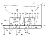
上記構成の冷蔵庫1において、図2に示す扉4aの閉止状態で所定の操作ボタン(不図示)が操作されると、駆動部58によって摺動子59が等速回転する。この時、摺動子59の回転方向B1は前方で枢支軸4cから離れる方向(図中、反時計回り)になっている。
摺動子59が所定角度(例えば、約45゜)回転し、図3に示すように、カム面60a上の始点Psに当接すると、摺動子59とカム面60aとの摺動が開始される。このため、扉4aの閉止状態から始点Psに当接するまで摺動子59が空転する空転期間が設けられる。空転期間により、パッキン80の吸着力によって扉4aを開く際の負荷が大きい開成動作の開始より前にモータ52の回転及びトルクを安定させることができる。
また、扉4aの閉止時に始点Psは枢支軸4cと減速ギア56の回転軸56a(図7参照)とを結ぶ直線よりも摺動子59の移動方向前方に配される。これにより、案内部60を扉4aよりも後方に突出させず、扉4aの上面に確実に配置することができる。このため、案内部60が本体部2の上方に延在することによる案内部60の強度低下及び扉4aの意匠性低下を防止することができる。
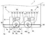
図4は、摺動子59が始点Psと中間点Pcとの間を摺動する第1摺動期間T1の冷蔵庫1の上面図を示している。摺動子59がカム面60a上の始点Psから更に回転し、中間点Pcの近傍に到達すると、パッキン80と本体部2の開口面3aの周縁部との密着が解除される。なお、中間点Pcの近傍であれば、摺動子59が中間点Pcを通過した直後にパッキン80と本体部2の開口面3aの周縁部との密着が解除されてもよい。
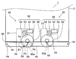
図5は、摺動子59が中間点Pcと終点Peとの間を摺動する第2摺動期間T2の冷蔵庫1の上面図を示している。摺動子59がカム面60a上の中間点Pcから更に回転すると、扉4aが開かれる。図6に示すように、摺動子59はカム面60a上の終点Peに到達してカム面60aから離れる。その後、扉4aは摺動子59がカム面60aから離れたときの付勢力によってさらに大きく開かれる。したがって、扉4aを開く際の負担を軽減することができる。
なお、扉4bは右方の扉開放装置50の摺動子59が回転方向B2(図2において、時計回り)に回転することにより扉4aと同様に開かれる。
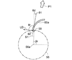
図7~図9は、摺動子59の移動方向LDとカム面60aの接線S1との成す角度θ2を説明するための平面図である。図7は摺動子59が始点Ps上に配されている状態を示している。図8は第2摺動期間T2の状態を示している。図9は摺動子59が終点Pe上に配されている状態を示している。矢印P1は扉4aの押出方向を示している。
摺動子59の回転角をθrとし、扉4aの開角度(扉4aの前面と開口面3aとの成す角度)をθdとする。また、扉4aの押出方向と摺動子59のカム面60aの接線S1との成す角度をθ1とし、摺動子59の移動方向LDとカム面60aの接線S1との成す角度θ2とする。本実施形態において、角度θ1、θ2は90°よりも小さくなっている。この場合、回転角θrと角度θ1と角度θ2と開角度θdとの和は180°になる。後述のように、本実施形態では摺動子59が始点Psから終点Peへ案内面60a上を摺動して回転角θrが大きくなるほど、角度θ1は小さくなるとともに角度θ2は大きくなる。
図10は第1摺動期間T1の扉4aの速度(開放速度)を説明するための平面図であり、図11は第2摺動期間T2の扉4aの速度(開放速度)を説明するための平面図である。なお、一点鎖線59´及び一点鎖線S11は所定の微小時間経過後の摺動子59及び接線S1の位置をそれぞれ示している。角度θ1は接線S1と扉4aの速度ベクトルVとの成す角度と等しく、角度θ2は接線S1と摺動子59の速度ベクトルLとの成す角度と等しい。そして、速度ベクトルV、Lの大きさをそれぞれ速さ|V|、|L|とすると、速さ|V|は式(1)で表される。
|V|=|L|(sinθ2/sinθ1)・・・(1)
本実施形態において、第2摺動期間T2では第1摺動期間T1よりも角度θ1が小さくなるとともに角度θ2が大きくなっている。このため、式(1)より、第2摺動期間T2の速さ|V|は第1摺動期間T1の速さ|V|よりも大きくなる。なお、本明細書において、速さ|V|を扉4aの速度(開放速度)という場合がある。
図12は本実施形態の扉開放装置50において、扉4aの移動距離(開放距離)毎に設定した角度θ1、θ2による速さ|V|の変化を示す図である。左の縦軸は速さ|V|(速度ベクトルVの大きさ)を示している。右の縦軸は角度θ1、θ2(単位:°)を示している。横軸は扉4aの移動距離(開放距離)を示し、扉4aの閉鎖状態を0としている。実線K1、K2はそれぞれ角度θ1、θ2の変化を示し、破線K3は速さ|V|の変化を示している。
また、扉4aの移動距離が0の地点が始点Psであり、移動距離が67の地点が終点Peとなるように、摺動子59の位置及び案内部60のカム面60aが設定される。そして、扉4aの移動距離が20のときに摺動子59は中間点Pcの近傍に到達する。
同図に示すように、角度θ1は第1摺動期間T1及び第2摺動期間T2において減少している。角度θ2は第1摺動期間T1では略一定であり、第2摺動期間T2では扉4aの移動距離が大きくなるのに従って増加している。速さ|V|は第1摺動期間T1及び第2摺動期間T2において増加し、摺動子59が終点Peに到達した時(第2摺動期間T2の終了時)において最大になっている。すなわち、摺動子59が終点Peに到達した時に扉4aの速度は最大になっている。この時、第1摺動期間T1における速さ|V|の変化を示すグラフ(破線K3参照)の平均傾きは、第2摺動期間T2における速さ|V|の変化を示すグラフの平均傾きよりも小さくなっている。すなわち、第1摺動期間T1の扉4aの加速度を平均した平均加速度A1は、第2摺動期間T2の扉4aの加速度を平均した平均加速度A2よりも小さくなっている。なお、平均加速度A1は摺動子59が始点Psでカム面60aに当たった直後以降の加速度を平均している。
扉4aは開口面3aの周縁部に密着するパッキン80を有している。また、冷蔵室3が冷却されるに従って冷蔵室3内の気圧が下がるため、閉鎖状態の扉4aは冷蔵室3の前面の開口面3aに吸着された状態となっている。したがって、閉鎖状態の扉4aを開ける場合には、まず、この吸着状態を解除するためにパッキン80の密着力及び冷蔵室3からの負圧力に打ち勝つだけの押圧力が必要となる。
そこで、本実施形態では、第1摺動期間T1における扉4aの平均加速度A1を小さくすることにより、モータ52の発生するトルクを扉4aの加速に費やさずに扉4aの押圧力に使用することができる。これにより、モータ52の負荷が第1摺動期間T1で過度に大きくなることを防止でき、駆動力の大きい大型のモータを使用せずとも確実に扉4aの閉鎖状態を解除することができる。
また、本実施形態では、摺動子59が中間点Pcの近傍に到達した際に、すなわち、第1摺動期間T1がほぼ終了した際に、パッキン80と開口面3aの周縁部との密着が解除される。なお、パッキン80と開口面3aの周縁部との密着が解除された状態とは、パッキン80の少なくとも一部と開口面3aの周縁部との間に隙間が生じた状態であり、より好ましくは、開口面3aの周縁部のうちの少なくとも一辺がパッキン80から離間した状態である。パッキン80と開口面3aの周縁部との間に隙間が生じると、この隙間から冷蔵室3内へ外気が流入するため、冷蔵室3の内外気圧差が解消される。したがって、扉4aを吸着する冷蔵室3からの負圧力が無くなる。さらに、パッキン80が開口面3aの周縁部のうちの少なくとも一辺から離間した状態では、離間した一辺に隣接する二辺に対向するパッキン80は、既に離間したパッキン80側の端部から容易に引き剥がせる状態になっている。このため、パッキン80の全体を開口面3aの周縁部から離間させるために大きな押圧力を必要としない。
したがって、本実施形態では、摺動子59が中間点Pcと終点Peとの間を摺動する第2摺動期間T2における扉4aの平均加速度A2を、第1摺動期間T1における扉4aの平均加速度A1よりも大きくしている。前述の通り、第1摺動期間T1ではモータ52の発生するトルクを扉4aの押圧力に費やすために扉4aの平均加速度を小さくしている。このため、第1摺動期間T1では扉4aの開放速度は大きくならない。そこで、第2摺動期間T2では、第1摺動期間T1よりも扉4aの平均加速度を大きくすることによって扉4aの開放速度が上昇し、摺動子59が終点Peに到達した時の扉4aの開放速度が大きくなるようにできる。
なお、第2摺動期間T2では扉4aを開口面3aの周縁部から離間させるために大きな押圧力を必要としなくなっているので、扉4aの平均加速度を大きくしてもモータ52の負荷が過度に大きくなることを防止できる。すなわち、モータ52の負荷は第1摺動期間T1及び第2摺動期間T2のいずれか一方で過度に大きくならず、第1摺動期間T1から第2摺動期間T2にわたってモータ52の負荷を均一化することができる。
本実施形態によると、第1摺動期間T1の扉4a、4bの加速度を平均した第1平均加速度A1は、第2摺動期間T2の扉4a、4bの加速度を平均した第2平均加速度A2よりも小さい。これにより、摺動子59が始点Psから中間点Pcに至るまでの扉4a、4bの平均加速度A1(第1平均加速度)が小さくなるため、駆動力の大きい大型のモータを用いる必要がなくなる。一方、摺動子59が中間点Pcを通過した後の扉4a、4bの平均加速度A2(第2平均加速度)は平均加速度A1よりも大きいため、扉4a、4bを勢いよく押し出すことができ、扉4a、4bを手動で開く範囲を小さくすることができる。したがって、扉開放装置50及びそれを備えた冷蔵庫1の製造コストを削減して利便性を向上させることができる。
また、扉4a、4bは開口面3aの周縁部に密着するパッキン80を有し、摺動子59が中間点Pcの近傍の到達した際にパッキン80と開口面3aの周縁部との密着が解除される。これにより、パッキン80と開口面3aの周縁部との密着が解除される直前または解除された直後に扉4a、4bの加速度を大きくすることができる。したがって、扉開放装置50のモータ52の負担を軽減しながら、扉4a、4bの開放速度を大きくすることができる。
また、第2摺動期間T2の扉4a、4bの加速度が常に正であると好ましい。これにより、第2摺動期間T2では扉4a、4bの開放速度は上昇し続けるため、摺動子59がカム面60aから離れることがない。したがって、第2摺動期間T2の全域を使用して扉4a、4bを加速することができ、摺動子59が終点Peに到達した時に扉4a、4bの速度を確実に大きくすることができる。その結果、扉4a、4bが確実に勢いよく押し出される。
また、第2摺動期間T2の扉4a、4bの加速度が増加すると好ましい。これにより、摺動子59が終点Peに到達した時に扉4aの速度をさらに大きくすることができる。これにより、扉4a、4bがより確実に勢いよく押し出される。
また、摺動子59が終点Pe上に配された際に扉4a、4bの押出方向(矢印P1)と摺動子59の移動方向LDとが直交してもよい。これにより、摺動子59が終点Pe上に配された際に、摺動子59と回転軸56aとを結ぶ直線と、摺動子59と枢支軸4cとを結ぶ直線とが、摺動子59で直交する。すなわち、終点Peでは摺動子59と枢支軸4cとを結ぶ直線が摺動子59の回転軌道円弧の接線となる。したがって、扉開放装置50の動作時に扉4a、4bの加速度をより大きくするとともに扉4a、4bの前方への移動距離を長くすることができ、扉4a、4bを手動で開く範囲をより小さくすることができる。
また、始点Psと中間点Pcとの間のカム面60aと、中間点Pcと終点Peとの間のカム面60aとは滑らかに接続されている。これにより、摺動子59はカム面60a上を円滑に摺動することができる。したがって、扉開放装置50は扉4a、4bを円滑に押し出すことができる。
なお、本体部2に枢支される扉4a、扉4bが本体部2の下部を開閉する場合は、本体部2の下面及び扉4a、4bの下面に扉開放装置50を配置してもよい。
<第2実施形態>
次に、本発明の第2実施形態について説明する。図13は第2実施形態の冷蔵庫1の左側面図を示している。説明の便宜上、前述の図1~図12に示す第1実施形態と同様の部分には同一の符号を付している。本実施形態は自閉機構部を備えている点が第1実施形態と異なっている。その他の部分は第1実施形態と同様である。
次に、本発明の第2実施形態について説明する。図13は第2実施形態の冷蔵庫1の左側面図を示している。説明の便宜上、前述の図1~図12に示す第1実施形態と同様の部分には同一の符号を付している。本実施形態は自閉機構部を備えている点が第1実施形態と異なっている。その他の部分は第1実施形態と同様である。
本体部2には枢支軸4cを形成するヒンジピン20(図14参照)を有して扉4aの上下を支持する上アングル21及び下アングル22が前方に突出して取り付けられる。以下、扉4aについて説明するが、扉4bも同様に支持される。
図14は図13のA部詳細図を示している。上アングル21は金属板から成り、金属製のヒンジピン20が下方に延びて立設される。扉4aにはヒンジピン20を軸支する軸孔26が設けられる。ヒンジピン20の座面と扉4aの上面との間には板バネ19が挟持され、板バネ19により扉4aが下方に付勢される。
図15は図13のB部詳細図を示している。下アングル22は金属板から成り、金属製のヒンジピン20が上方に延びて立設される。下アングル22上には下ヒンジ部材30が取り付けられる。扉4aの下面には下ヒンジ部材30に摺接する上ヒンジ部材40が取り付けられる。上ヒンジ部材40にはヒンジピン20を軸支する軸孔43(図17参照)が設けられる。
図16は下ヒンジ部材30を上方から見た斜視図を示している。下ヒンジ部材30は樹脂成形品により形成され、下アングル22(図15参照)にネジ止めされる基台部31の一端に貫通孔33が設けられる。貫通孔33には下アングル22に立設したヒンジピン20が挿通される。
貫通孔33の周囲にはヒンジピン20と同心の円筒面の内壁を有する嵌合部32が設けられる。ヒンジピン20の座面を形成する嵌合部32の底面には所定の角度範囲に水平面から成る複数の平坦部34が点対称に設けられる。また、平坦部34に連続する所定の角度範囲には平坦部34に対して下方に傾斜する複数のスロープ35が点対称に設けられる。
図17は上ヒンジ部材40を下方から見た斜視図を示している。上ヒンジ部材40は樹脂成形品により形成され、扉4aにネジ止めされる基台部41の一端に筒部48が突設される。筒部48は扉4a内に埋設され、内部に軸孔43が形成される。軸孔43は下ヒンジ部材30の貫通孔33(図16参照)に挿通したヒンジピン20が嵌合し、ヒンジピン20を軸支する。
軸孔43の周囲には下ヒンジ部材30の嵌合部32に嵌合する凸部42が形成される。凸部42の下面には所定の角度範囲に水平面から成る複数の平坦部44が点対称に設けられる。また、平坦部44に連続する所定の角度範囲には平坦部44に対して上方に傾斜する複数のスロープ45が点対称に設けられる。
上記構成の冷蔵庫1において、第1実施形態と同様に、図2に示す扉4aの閉止状態で所定の操作ボタン(不図示)が操作されると、駆動部58によって摺動子59が等速回転する。これにより、第1実施形態と同様に、扉4aが開かれる。
一方、扉4aを閉じる方向に回動させると、下ヒンジ部材30のスロープ35(図16参照)と上ヒンジ部材40のスロープ45(図17参照)とが摺動を開始する。これにより、扉4aは自重の付勢力によって降下しながら閉じる方向に回動して自閉する。すなわち、スロープ35、45は摺動開始位置から扉4aの閉止位置までの自閉区間で扉4aを自重により自閉させる自閉機構部を構成する。この時、板バネ19の付勢力によってより確実に扉4aを自閉させることができる。自閉区間では扉4aは自重によって加速しながら回動する。
また、扉開放装置50の動作時に摺動子59が終点Peを通過した際に下ヒンジ部材30のスロープ35(図16参照)上に上ヒンジ部材40のスロープ45(図17参照)が配される。これにより、摺動子59が終点Pe上に配された際に扉4aが自閉区間内に配される。なお、扉4bは扉4aと同様に自閉機構部により自閉する。
これにより、扉4a、4bの前方近傍に障害物等が存在する場合など、摺動子59が終点Peを通過したときに扉4a、4bが前方に開放できない場合であっても、扉4a、4bは自閉区間内に配されるため自閉する。このため、扉4a、4bを確実に閉鎖状態にすることができる。一方、摺動子59が終点Peを通過した後は扉4a、4bは開放方向に加速されないため、自閉機構部によって減速する。このため、摺動子59が終点Pe上に配されている時に扉4a、4bが十分な開放速度を有していないと、扉4a、4bを手動で開く範囲が大きくなるおそれや、扉4a、4bが自閉機構部によって閉鎖するおそれがある。
本実施形態によると、第1実施形態と同様に扉開放装置50により扉4a、4bを勢いよく押し出すことができる。すなわち、扉開放装置50により扉4a、4bは十分な開放速度を有することができる。このため、通常使用時は扉4a、4bを勢いよく開放させて自閉機構部を乗り越えさせることで、扉4a、4bの開放状態を維持することができ、冷蔵庫1の利便性を向上させることができる。一方、扉4a、4bの前方近傍に障害物が存在する場合等の異常時であっても、自閉機構部によって扉4a、4bを確実に閉鎖状態にすることができる。
本実施形態によると、扉4a、4bの前方近傍に障害物等がない正常時には、第1実施形態と同様に、扉4a、4bを勢いよく開放させて扉4a、4bを手動で開く範囲を小さくすることができる。また、スロープ35、45により形成される自閉機構部によって扉4a、4bが自閉し、摺動子59が終点Pe上に配された際に扉4a、4bが自閉区間内に配される。これにより、扉4a、4bの前方近傍に障害物等が存在する場合であっても、自閉機構部によって扉4a、4bを確実に閉鎖状態にすることができる。したがって、扉4a、4bの不完全な閉鎖状態による冷蔵室3からの冷気漏れを防止することができる。
<第3実施形態>
次に、本発明の第3実施形態について説明する。図18は本実施形態の扉開放装置50において、扉4aの移動距離(開放距離)毎に設定した角度θ1、θ2による速さ|V|の変化を示す図である。説明の便宜上、前述の図1~図12に示す第1実施形態と同様の部分には同一の符号を付している。本実施形態はカム面60aの構成が第1実施形態と異なっている。その他の部分は第1実施形態と同様である。
次に、本発明の第3実施形態について説明する。図18は本実施形態の扉開放装置50において、扉4aの移動距離(開放距離)毎に設定した角度θ1、θ2による速さ|V|の変化を示す図である。説明の便宜上、前述の図1~図12に示す第1実施形態と同様の部分には同一の符号を付している。本実施形態はカム面60aの構成が第1実施形態と異なっている。その他の部分は第1実施形態と同様である。
同図に示すように、第1摺動期間T1の開始時から第2摺動期間T2の終了時にわたって、角度θ1は徐々に減少するとともに角度θ2は徐々に増加している。また、速さ|V|は摺動子59が始点Psから終点Peへ向かうほど大きくなり、摺動子59が終点Peに到達した時(第2摺動期間T2の終了時)に最も大きくなっている。すなわち、第1実施形態と同様に、摺動子59が終点Peに到達した時に扉4aの速度は最大になっている。また、第1実施形態と同様に、第1摺動期間T1の扉4aの加速度を平均した平均加速度A1は、第2摺動期間T2の扉4aの加速度を平均した平均加速度A2よりも小さくなっている。
また、第1実施形態と同様に、モータ52の負荷は第1摺動期間T1及び第2摺動期間T2のいずれか一方で過度に大きくならず、第1摺動期間T1から第2摺動期間T2にわたってモータ52の負荷を均一化することができる。
本実施形態でも第1実施形態と同様の効果を奏することができる。また、本実施形態では、第1摺動期間T1の開始時から角度θ2を徐々に増加させているため、第1摺動期間T1の終了時までに扉4a、4bの速度を緩やかに上昇させることができ、第2摺動期間T2の開始時に扉4a、4bの加速度を急激に上昇させる必要がなくなる。したがって、例えば、扉4a、4bが比較的小型・軽量でパッキン80や庫内負圧に抗する押圧力が大きくなくてもよい場合などに、モータ52をより小型化しながら、扉4a、4bを手動で開く範囲を小さくすることができる。
<第4実施形態>
次に、本発明の第4実施形態について説明する。図19は本実施形態の扉開放装置50において、扉4aの移動距離(開放距離)毎に設定した角度θ1、θ2による速さ|V|の変化を示す図である。説明の便宜上、前述の図1~図12に示す第1実施形態と同様の部分には同一の符号を付している。本実施形態はカム面60aの構成が第1実施形態と異なっている。その他の部分は第1実施形態と同様である。
次に、本発明の第4実施形態について説明する。図19は本実施形態の扉開放装置50において、扉4aの移動距離(開放距離)毎に設定した角度θ1、θ2による速さ|V|の変化を示す図である。説明の便宜上、前述の図1~図12に示す第1実施形態と同様の部分には同一の符号を付している。本実施形態はカム面60aの構成が第1実施形態と異なっている。その他の部分は第1実施形態と同様である。
同図に示すように、角度θ1は第1摺動期間T1において略線形的に減少するとともに、第2摺動期間T2において急激に減少している。一方、角度θ2は第1摺動期間T1において略一定であり、第2摺動期間T2において急激に増加している。そして、速さ|V|は第1摺動期間T1において略一定であり、第2摺動期間T2において略線形的に増加し、摺動子59が終点Peに到達した時(第2摺動期間T2の終了時)に最も大きくなっている。すなわち、第1実施形態と同様に、摺動子59が終点Peに到達した時に扉4aの速度は最大になっている。
また、第1実施形態と同様に、第1摺動期間T1の扉4aの加速度を平均した平均加速度A1は、第2摺動期間T2の扉4aの加速度を平均した平均加速度A2よりも小さくなっている。本実施形態において、第1摺動期間T1では扉4aの速度は略一定であり、第2摺動期間T2では扉4aの加速度は略一定になっている。
また、第1実施形態と同様に、モータ52の負荷は第1摺動期間T1及び第2摺動期間T2のいずれか一方で過度に大きくならず、第1摺動期間T1から第2摺動期間T2にわたってモータ52の負荷を均一化することができる。
本実施形態でも第1実施形態と同様の効果を奏することができる。また、本実施形態によると、第1摺動期間T1の摺動子59の移動方向LDとカム面60aの接線S1との成す角度θ2が略一定であるとともに、第2摺動期間T2の角度θ2が増加する。そして、第1摺動期間T1において、速さ|V|は略一定、すなわち扉4a、4bの加速度は略0であり、第2摺動期間T2において、速さ|V|は略線形的に増加、すなわち扉4a、4bの加速度が略一定となるようにしている。これにより、第1摺動期間T1ではモータ52のトルクのほぼ全てを扉4a、4bの吸着力解除に使用することができ、第2摺動期間T2ではモータ52の負担をほぼ一定に保ちながら扉4a、4bの速度を上昇させることができる。したがって、例えば、扉4a、4bや冷蔵室3が比較的大型で、パッキン80の本体部2に対する吸着力や冷蔵室3の庫内負圧が大きい場合でもモータ52の負担の変動を小さくしながら、効率よく扉4a、4bを勢いよく押し出すことができる。
<第5実施形態>
次に、本発明の第5実施形態について説明する。図20は第5実施形態の冷蔵庫1の冷凍室5の平面断面図を示している。説明の便宜上、前述の図1~図12に示す第1実施形態と同様の部分には同一の符号を付している。本実施形態は扉開放装置50により冷凍室5の扉6を開く点が第1実施形態と異なっている。その他の部分は第1実施形態と同様である。
次に、本発明の第5実施形態について説明する。図20は第5実施形態の冷蔵庫1の冷凍室5の平面断面図を示している。説明の便宜上、前述の図1~図12に示す第1実施形態と同様の部分には同一の符号を付している。本実施形態は扉開放装置50により冷凍室5の扉6を開く点が第1実施形態と異なっている。その他の部分は第1実施形態と同様である。
冷凍室5の扉6は収納ケース5bと一体に形成され、移動機構70によって前後にスライドする。移動機構70はレール71、ローラ(不図示)及びフレーム(不図示)を有する。レール71は冷凍室5の両側壁に取り付けられ、前後に延びて形成される。ローラはレールの前方に配され、水平な回転軸を有して冷凍室5の両側壁に軸支される。フレームは金属により形成され、扉6の左右の端部からそれぞれ後方に延びる。両フレーム上に収納ケース5bが載置される。フレームがレール上を摺動することにより扉6は前後にスライドすることができる。この時、ローラはフレームの下面上を転動する。
また、フレームの下面の前端部には後方へ行くほど下方に傾斜する傾斜面が形成される。扉6を閉じる方向(後方)にスライドさせると、ローラの傾斜面上での転動が開始される。これにより、扉6は自重の付勢力によって降下しながら閉じる方向にスライドして自閉する。すなわち、傾斜面はローラの転動開始位置から扉6の閉止位置までの自閉区間で扉6を自重により自閉させる自閉機構部を構成する。自閉区間では扉6は自重によって加速しながらスライドする。
収納ケース5bよりも下方には扉6を開く扉開放装置50が設けられる。駆動部58は冷凍室5の底壁に取り付けられた支持部材51上に設置される。案内部60は扉6に取り付けられる。
上記構成の冷蔵庫において、図20に示す扉6の閉止状態で所定の操作ボタン(不図示)が操作されると、駆動部58によって摺動子59が等速回転する。これにより、図21~図23に示すように、摺動子59が扉6のカム面60aに摺動し、摺動子59が終点Peでカム面60aから離れて扉6が前方にスライドして開かれる。この時、摺動子59の回転方向B1は前方で冷凍室5の左側壁から離れる方向(図中、反時計回り)になっている。また、図22に示すように、摺動子59が中間点Pcの近傍に到達した際にパッキン80と本体部2の開口面5cの周縁部との密着が解除される。
また、本実施形態では、図7~図9において、扉6の押出方向が垂直方向(図7の矢印P1)になるため、本実施形態の角度θ1は第1実施形態の角度θ1と開角度θdとの和に相当する。また、開角度θdは約5°で小さいため、本実施形態の引出式の扉6の場合も第1実施形態の回動式の扉4a、4bの場合と同様に考えることができる。
また、第2実施形態と同様に、摺動子59が終点Pe上に配された際に扉6が自閉区間内に配される。
本実施形態のように前後にスライドする扉6(引出式扉)でも第1実施形態と同様な効果を得ることができる。
なお、本実施形態において、扉開放装置50を野菜室7に配置して扉開放装置50により扉8を開いてもよい。
また、第3実施形態及び第4実施形態において、冷蔵庫1は第2実施形態の自閉機構部と同様の自閉機構部を備えてもよい。
また、第1実施形態~第5実施形態の扉開放装置50を冷蔵庫1以外の機器等に用いてもよい。
本発明によると、扉を開放する扉開放装置及びそれを備えた冷蔵庫に利用することができる。
1 冷蔵庫
2 本体部
3 冷蔵室
3a、5c、7c 開口面
4a、4b、6、8 扉
4c、4d 枢支軸
5 冷凍室
5b 収納ケース
7 野菜室
19 板バネ
20 ヒンジピン
21 上アングル
22 下アングル
26 軸孔
30 下ヒンジ部材
31 基台部
32 嵌合部
33 貫通孔
34 平坦部
35 スロープ
40 上ヒンジ部材
41 基台部
42 凸部
43 軸孔
44 平坦部
45 スロープ
50 扉開放装置
51 支持部材
52 モータ
53 ウォーム
54 ウォームホイール
55 減速ギア
56 減速ギア(回転体)
56a 回転軸
57 中間ギア
58 駆動部
59 摺動子
60 案内部
60a カム面
70 移動機構
71 レール
80 パッキン
B1、B2 回転方向
Ps 始点
Pc 中間点
Pe 終点
FL 床面
2 本体部
3 冷蔵室
3a、5c、7c 開口面
4a、4b、6、8 扉
4c、4d 枢支軸
5 冷凍室
5b 収納ケース
7 野菜室
19 板バネ
20 ヒンジピン
21 上アングル
22 下アングル
26 軸孔
30 下ヒンジ部材
31 基台部
32 嵌合部
33 貫通孔
34 平坦部
35 スロープ
40 上ヒンジ部材
41 基台部
42 凸部
43 軸孔
44 平坦部
45 スロープ
50 扉開放装置
51 支持部材
52 モータ
53 ウォーム
54 ウォームホイール
55 減速ギア
56 減速ギア(回転体)
56a 回転軸
57 中間ギア
58 駆動部
59 摺動子
60 案内部
60a カム面
70 移動機構
71 レール
80 パッキン
B1、B2 回転方向
Ps 始点
Pc 中間点
Pe 終点
FL 床面
Claims (7)
- 開口面を有する本体部と、前記開口面を開閉する扉と、前記本体部に配して回転軸を中心に回転する回転体と、前記回転体を駆動するモータと、前記回転体に配される摺動子と、前記扉に配されるとともに前記摺動子を案内するカム面とを備え、前記摺動子が前記カム面上の始点と終点との間を摺動して前記扉を開く扉開放装置において、
前記摺動子が前記始点と前記終点との間の所定の中間点と前記始点との間を摺動する第1摺動期間の前記扉の加速度を平均した第1平均加速度は、前記摺動子が前記中間点と前記終点との間を摺動する第2摺動期間の前記扉の加速度を平均した第2平均加速度よりも小さいことを特徴とする扉開放装置。 - 前記扉は前記開口面の周縁部に密着するパッキンを有し、前記摺動子が前記中間点の近傍に到達した際に前記パッキンと前記周縁部との密着が解除されることを特徴とする請求項1に記載の扉開放装置。
- 前記第2摺動期間の前記扉の加速度が常に正であることを特徴とする請求項1または請求項2に記載の扉開放装置。
- 前記第2摺動期間の前記扉の加速度が一定または増加することを特徴とする請求項3に記載の扉開放装置。
- 前記第1摺動期間の前記摺動子の移動方向と前記カム面の接線との成す角度が略一定であるとともに、前記第2摺動期間の前記角度が増加することを特徴とする請求項4に記載の扉開放装置。
- 所定の自閉区間で前記扉を付勢して自閉させる自閉機構部を備え、前記摺動子が前記終点上に配された際に前記扉が前記自閉区間内に配されることを特徴とする請求項1~請求項5のいずれかに記載の扉開放装置。
- 請求項1~請求項6のいずれかに記載の扉開放装置を備えたことを特徴とする冷蔵庫。
Priority Applications (2)
| Application Number | Priority Date | Filing Date | Title |
|---|---|---|---|
| CN201780091479.6A CN110709657B (zh) | 2017-05-30 | 2017-08-24 | 门打开装置及冰箱 |
| JP2019521939A JP6889776B2 (ja) | 2017-05-30 | 2017-08-24 | 冷蔵庫 |
Applications Claiming Priority (2)
| Application Number | Priority Date | Filing Date | Title |
|---|---|---|---|
| JP2017106890 | 2017-05-30 | ||
| JP2017-106890 | 2017-05-30 |
Publications (1)
| Publication Number | Publication Date |
|---|---|
| WO2018220872A1 true WO2018220872A1 (ja) | 2018-12-06 |
Family
ID=64456410
Family Applications (1)
| Application Number | Title | Priority Date | Filing Date |
|---|---|---|---|
| PCT/JP2017/030295 Ceased WO2018220872A1 (ja) | 2017-05-30 | 2017-08-24 | 扉開放装置及び冷蔵庫 |
Country Status (4)
| Country | Link |
|---|---|
| JP (1) | JP6889776B2 (ja) |
| CN (1) | CN110709657B (ja) |
| TW (1) | TWI682138B (ja) |
| WO (1) | WO2018220872A1 (ja) |
Families Citing this family (4)
| Publication number | Priority date | Publication date | Assignee | Title |
|---|---|---|---|---|
| CN110892218B (zh) * | 2017-07-26 | 2021-10-12 | 夏普株式会社 | 门开闭机构 |
| KR20220018705A (ko) | 2020-08-07 | 2022-02-15 | 엘지전자 주식회사 | 냉장고 |
| CN112049539A (zh) * | 2020-08-26 | 2020-12-08 | 珠海格力电器股份有限公司 | 一种开合控制方法、装置、开合设备及冰箱 |
| KR20260023393A (ko) * | 2024-08-09 | 2026-02-20 | 삼성전자주식회사 | 냉장고 |
Citations (5)
| Publication number | Priority date | Publication date | Assignee | Title |
|---|---|---|---|---|
| JP2007278695A (ja) * | 2007-07-26 | 2007-10-25 | Toshiba Corp | 冷蔵庫の扉開放装置 |
| JP2008196839A (ja) * | 2007-03-30 | 2008-08-28 | Hitachi Appliances Inc | 冷蔵庫 |
| US20110016907A1 (en) * | 2009-07-22 | 2011-01-27 | Lg Electronics Inc. | Refrigerator |
| JP2015190692A (ja) * | 2014-03-28 | 2015-11-02 | 日本電産サンキョー株式会社 | 冷蔵庫用引き出し装置 |
| JP2016109396A (ja) * | 2014-12-10 | 2016-06-20 | 日立アプライアンス株式会社 | 冷蔵庫 |
Family Cites Families (6)
| Publication number | Priority date | Publication date | Assignee | Title |
|---|---|---|---|---|
| JP3505080B2 (ja) * | 1998-03-06 | 2004-03-08 | ホシザキ電機株式会社 | 貯蔵庫の扉装置 |
| US8099970B2 (en) * | 2006-12-08 | 2012-01-24 | Samsung Electronics Co., Ltd. | Refrigerator door opening device and control method thereof |
| JP2010025461A (ja) * | 2008-07-22 | 2010-02-04 | Hitachi Appliances Inc | 冷蔵庫 |
| JP6180861B2 (ja) * | 2013-09-13 | 2017-08-16 | 日立アプライアンス株式会社 | 開扉装置及びこれを備えた機器 |
| EP3998445B1 (en) * | 2015-07-30 | 2025-09-03 | LG Electronics Inc. | Refrigerator |
| CN105113905B (zh) * | 2015-09-09 | 2016-09-07 | 山东大学 | 一种基于凸轮机构的对开门冰箱自动开门装置 |
-
2017
- 2017-08-24 JP JP2019521939A patent/JP6889776B2/ja active Active
- 2017-08-24 WO PCT/JP2017/030295 patent/WO2018220872A1/ja not_active Ceased
- 2017-08-24 CN CN201780091479.6A patent/CN110709657B/zh active Active
- 2017-08-30 TW TW106129606A patent/TWI682138B/zh active
Patent Citations (5)
| Publication number | Priority date | Publication date | Assignee | Title |
|---|---|---|---|---|
| JP2008196839A (ja) * | 2007-03-30 | 2008-08-28 | Hitachi Appliances Inc | 冷蔵庫 |
| JP2007278695A (ja) * | 2007-07-26 | 2007-10-25 | Toshiba Corp | 冷蔵庫の扉開放装置 |
| US20110016907A1 (en) * | 2009-07-22 | 2011-01-27 | Lg Electronics Inc. | Refrigerator |
| JP2015190692A (ja) * | 2014-03-28 | 2015-11-02 | 日本電産サンキョー株式会社 | 冷蔵庫用引き出し装置 |
| JP2016109396A (ja) * | 2014-12-10 | 2016-06-20 | 日立アプライアンス株式会社 | 冷蔵庫 |
Also Published As
| Publication number | Publication date |
|---|---|
| TW201901104A (zh) | 2019-01-01 |
| TWI682138B (zh) | 2020-01-11 |
| CN110709657B (zh) | 2021-12-28 |
| CN110709657A (zh) | 2020-01-17 |
| JP6889776B2 (ja) | 2021-06-18 |
| JPWO2018220872A1 (ja) | 2020-04-02 |
Similar Documents
| Publication | Publication Date | Title |
|---|---|---|
| WO2018220872A1 (ja) | 扉開放装置及び冷蔵庫 | |
| US10724287B2 (en) | Refrigerator | |
| KR101972785B1 (ko) | 냉장고 | |
| CN100545557C (zh) | 冰箱及其开门装置 | |
| CN110068186A (zh) | 冰箱 | |
| JP2010025461A (ja) | 冷蔵庫 | |
| WO2023124619A1 (zh) | 冰箱 | |
| CN223106502U (zh) | 门体组件和制冷设备 | |
| CN111425099B (zh) | 开关门系统以及开门家电 | |
| WO2019021506A1 (ja) | 扉開閉機構 | |
| JP7043359B2 (ja) | 扉駆動装置および冷蔵庫 | |
| CN112212593B (zh) | 一种冰箱 | |
| WO2022083373A1 (zh) | 冰箱 | |
| CN106288273B (zh) | 面板驱动机构 | |
| US20250250842A1 (en) | Door opening and closing device and electrical apparatus | |
| CN112211517B (zh) | 一种冰箱 | |
| CN112212595B (zh) | 一种冰箱 | |
| JP6894967B2 (ja) | 扉開放装置及び冷蔵庫 | |
| US20250237104A1 (en) | Door opening and closing device and electrical apparatus | |
| TWI662242B (zh) | 門的開裝置、門的開閉裝置及冰箱 | |
| CN116624054A (zh) | 一种开关门装置和电器设备 | |
| JP2025069852A (ja) | 冷蔵庫 | |
| KR20060122096A (ko) | 냉장고의 도어 개폐 장치 | |
| CN117432304A (zh) | 一种可倾斜门体的安装支架、装置和装置的打开方法 | |
| CN113738206A (zh) | 冰箱 |
Legal Events
| Date | Code | Title | Description |
|---|---|---|---|
| 121 | Ep: the epo has been informed by wipo that ep was designated in this application |
Ref document number: 17911821 Country of ref document: EP Kind code of ref document: A1 |
|
| ENP | Entry into the national phase |
Ref document number: 2019521939 Country of ref document: JP Kind code of ref document: A |
|
| NENP | Non-entry into the national phase |
Ref country code: DE |
|
| 122 | Ep: pct application non-entry in european phase |
Ref document number: 17911821 Country of ref document: EP Kind code of ref document: A1 |