WO2018216508A1 - 移載装置及び栽培システム - Google Patents
移載装置及び栽培システム Download PDFInfo
- Publication number
- WO2018216508A1 WO2018216508A1 PCT/JP2018/018310 JP2018018310W WO2018216508A1 WO 2018216508 A1 WO2018216508 A1 WO 2018216508A1 JP 2018018310 W JP2018018310 W JP 2018018310W WO 2018216508 A1 WO2018216508 A1 WO 2018216508A1
- Authority
- WO
- WIPO (PCT)
- Prior art keywords
- unit
- memory
- transfer
- transfer device
- camera
- Prior art date
- Legal status (The legal status is an assumption and is not a legal conclusion. Google has not performed a legal analysis and makes no representation as to the accuracy of the status listed.)
- Ceased
Links
Images




Classifications
-
- A—HUMAN NECESSITIES
- A01—AGRICULTURE; FORESTRY; ANIMAL HUSBANDRY; HUNTING; TRAPPING; FISHING
- A01G—HORTICULTURE; CULTIVATION OF VEGETABLES, FLOWERS, RICE, FRUIT, VINES, HOPS OR SEAWEED; FORESTRY; WATERING
- A01G31/00—Soilless cultivation, e.g. hydroponics
- A01G31/02—Special apparatus therefor
- A01G31/04—Hydroponic culture on conveyors
-
- A—HUMAN NECESSITIES
- A01—AGRICULTURE; FORESTRY; ANIMAL HUSBANDRY; HUNTING; TRAPPING; FISHING
- A01G—HORTICULTURE; CULTIVATION OF VEGETABLES, FLOWERS, RICE, FRUIT, VINES, HOPS OR SEAWEED; FORESTRY; WATERING
- A01G9/00—Cultivation in receptacles, forcing-frames or greenhouses; Edging for beds, lawn or the like
-
- B—PERFORMING OPERATIONS; TRANSPORTING
- B65—CONVEYING; PACKING; STORING; HANDLING THIN OR FILAMENTARY MATERIAL
- B65G—TRANSPORT OR STORAGE DEVICES, e.g. CONVEYORS FOR LOADING OR TIPPING, SHOP CONVEYOR SYSTEMS OR PNEUMATIC TUBE CONVEYORS
- B65G1/00—Storing articles, individually or in orderly arrangement, in warehouses or magazines
-
- B—PERFORMING OPERATIONS; TRANSPORTING
- B65—CONVEYING; PACKING; STORING; HANDLING THIN OR FILAMENTARY MATERIAL
- B65G—TRANSPORT OR STORAGE DEVICES, e.g. CONVEYORS FOR LOADING OR TIPPING, SHOP CONVEYOR SYSTEMS OR PNEUMATIC TUBE CONVEYORS
- B65G1/00—Storing articles, individually or in orderly arrangement, in warehouses or magazines
- B65G1/02—Storage devices
- B65G1/04—Storage devices mechanical
-
- Y—GENERAL TAGGING OF NEW TECHNOLOGICAL DEVELOPMENTS; GENERAL TAGGING OF CROSS-SECTIONAL TECHNOLOGIES SPANNING OVER SEVERAL SECTIONS OF THE IPC; TECHNICAL SUBJECTS COVERED BY FORMER USPC CROSS-REFERENCE ART COLLECTIONS [XRACs] AND DIGESTS
- Y02—TECHNOLOGIES OR APPLICATIONS FOR MITIGATION OR ADAPTATION AGAINST CLIMATE CHANGE
- Y02P—CLIMATE CHANGE MITIGATION TECHNOLOGIES IN THE PRODUCTION OR PROCESSING OF GOODS
- Y02P60/00—Technologies relating to agriculture, livestock or agroalimentary industries
- Y02P60/20—Reduction of greenhouse gas [GHG] emissions in agriculture, e.g. CO2
- Y02P60/21—Dinitrogen oxide [N2O], e.g. using aquaponics, hydroponics or efficiency measures
Definitions
- the present invention relates to a transfer device for transferring a cultivation unit used in a plant factory, for example, and a cultivation system using the transfer device.
- Plant factories that grow plants by controlling the growth environment are increasing regardless of their size.
- automation of operations in cultivation processes such as sowing, sprouting, greening, seedling selection, seedling raising, seedling transplanting, growth, and harvesting has been promoted.
- Vegetables cultivated in plant factories can be supplied in a stable manner that is not affected by the weather, can be cultivated with optimized culture materials, have high nutritional value, and can be grown without pesticides due to the absence of insect damage. It has excellent points such as being.
- Patent Document 1 and Patent Document 2 shelves capable of placing several stages of cultivation containers containing plants in the height direction are provided and a large number of cultivation containers are placed, and light from the light source is directed toward the cultivation containers.
- the cultivation system to irradiate performing control which mounts each cultivation container in an appropriate position is disclosed.
- a monitor camera is used to enable visual confirmation of the growth state of the plant in the cultivation container. For example, by providing a monitor camera on a moving device that moves the cultivation container, the attendant checks the video output from the monitor camera, and the attendant moves to move and remove the cultivation container according to the confirmed result. Operate the device.
- JP 2000-209970 A Japanese Patent Application Laid-Open No. 2001-078568
- the present invention has been made in view of such circumstances, and provides a transfer device that speeds up recovery when trouble occurs and achieves efficient automatic operation, and a cultivation system using the transfer device. For the purpose.
- the transfer device has a transfer unit that moves along a frontage direction of a storage shelf having a plurality of storage portions arranged side by side in the vertical and horizontal directions, and moves up and down along the height direction.
- a camera provided in the transfer unit, a first memory for sequentially storing images output from the camera, A second memory for storing the video; and a state input unit for inputting a signal indicating an operation state of the transfer apparatus, and storing the signal input by the state input unit as a trigger in the first memory Of the video to be recorded, the video for a predetermined time taken by the camera before and after the trigger timing is stored in the second memory.
- the state input unit inputs a signal indicating a load, speed, acceleration, temperature, or vibration state of a motor that moves the transfer unit in the frontage direction and the height direction
- the trigger is a comparison result of a signal level of an input signal with a predetermined value or a change in state indicated by the signal.
- the transfer apparatus includes a control unit that controls the movement and operation of the transfer unit, and the state input unit transfers a signal indicating the presence or absence of a transfer object in the transfer unit. Input from the unit, the control unit generates the trigger based on a movement or control content for the transfer unit and a signal indicating the presence or absence of the transferred object.
- the state input unit inputs a signal indicating the state of the emergency stop switch of the transfer device, and when the state indicates that an emergency stop has been made, the trigger is Generated.
- the camera, the first memory, and the second memory are provided in a camera unit provided in the transfer unit, and the camera unit inputs the trigger. Images for a predetermined time taken by the camera in the camera unit before and after the trigger timing are stored in the second memory.
- the first memory and the second memory are provided in the control unit, and the control unit inputs an image output from the camera and moves or moves relative to the transfer unit.
- the time information is associated with the log data indicating the control contents and sequentially stored in the first memory.
- the second memory is a non-volatile memory that is detachably attached to the transfer device.
- the transfer device further includes a communication unit that transmits information wirelessly or by wire, and the second memory is provided in an external storage device outside the transfer device, and the communication unit includes: The video for the predetermined time is transmitted to the second memory.
- the cultivation system has a cultivation shelf having a plurality of storage units for accommodating a plant and a cultivation unit containing the plant medium, and a transfer unit that moves vertically and horizontally along the frontage direction of the cultivation shelf.
- the transfer device includes a camera provided in the transfer unit; A first memory that sequentially stores video output from the camera, a second memory that stores the video, and a state input unit that inputs a signal indicating an operation state of the transfer device, Of the video stored in the first memory with the signal input from the state input unit as a trigger, the video for a predetermined time taken by the camera before and after the trigger timing is displayed in the second memory.
- the operation state of the transfer device indicates a trouble occurrence or when the trouble occurrence can be predicted
- this is used as a trigger to photograph with a camera provided in the transfer unit that moves and moves up and down. Can be left.
- it is easy for the operator to check the reproduction of the video data afterwards, so that the situation at the time of the trouble can be easily understood and reproduced, and the operation of the transfer device can be restored quickly.
- a signal indicating the load, speed, acceleration, temperature, or vibration state of the motor used for moving the transfer unit is used as a signal indicating the operation state of the transfer device.
- the trouble occurrence state can be stored as a video image triggered by motor overload, excessive speed, excessive frequency, or the like.
- the contents of the control to the transfer unit (whether the transfer object is to be taken in or whether the transfer object is to be mounted on the transfer destination) and the transfer unit that can be detected by the transfer unit
- the situation of trouble occurrence can be stored as a video when the state such as the presence or absence of an object cannot be matched.
- the operation of the transfer device when the emergency stop is performed can be reproduced as a video.
- an existing camera unit incorporating a camera element for example, an internal memory of a general-purpose digital camera and a removable external memory.
- video data is stored in a memory provided on the control unit side that controls the movement and operation of the transfer device and the transfer unit.
- the control unit can easily associate the movement of the transfer device to the transfer unit or the control content with the time information together with the video data.
- the control content may be output to the camera side and stored together with the video data on the camera side.
- the video is transmitted by the communication unit, and the video data is stored in the memory of the device outside the transfer device.
- the trouble occurrence status can be reproduced and confirmed at a place away from the operation site, and the operator can estimate the cause of the trouble occurring in the transfer device. Is possible.
- FIG. 10 is a flowchart illustrating an example of a recording procedure by the recording system according to the second embodiment.
- FIG. 6 is a schematic diagram illustrating a synchronization image of log data and video data stored in a second embodiment.
- 10 is a block diagram showing a configuration of a recording system applied in Embodiment 3.
- FIG. 10 is a flowchart illustrating an example of a recording procedure by the recording system according to the third embodiment.
- the plant factory automatically grows the cultivation unit that accommodates the cultivation unit in which the plant seedling is transplanted in the growing step after transplanting the seedling in each step of cultivation, and automatically the cultivation unit with respect to the cultivation shelf.
- a cultivation system including a device to be transferred manually.
- FIG. 1 is a schematic perspective view of a cultivation system 100 in the present embodiment.
- the cultivation system 100 in the present embodiment includes a cultivation shelf 1 and a transfer device 2.
- the cultivation shelf 1 is configured by arranging a plurality of multistage shelves in the left-right direction that can accommodate a plurality of cultivation units in the up-down direction.
- the cultivation unit is in a state in which a medium in which a seedling of a plant to be cultivated is buried in each hole of a rectangular cultivation panel in which a plurality of holes are provided vertically and horizontally. .
- the transfer device 2 includes a transfer unit that moves in the frontage direction (left-right direction) and the height direction (up-down direction) of the cultivation shelf 1, and uses the transfer unit to transfer the cultivation unit from other places to the cultivation shelf 1. It is a device that is placed in or taken out from each accommodating portion.
- the cultivation shelf 1 includes a frame 11 serving as a framework, a guide rail 12 that receives the cultivation unit, a basket 13 for forming a flow of a culture solution that is constantly supplied to the lower part of each cultivation unit that is housed, A collar receiver 14 and a support portion 15 that support the collar 13 are provided.
- Each accommodation part of the cultivation shelf 1 is comprised by partitioning the flame
- the frame 11 is configured by arranging a plurality of gate-shaped frame members formed by connecting the upper portions of a pair of left and right support columns with horizontal beams in the front-rear direction and connecting the upper portions of these frame members with vertical beams.
- the guide rail 12 is provided inside the left and right support columns in parallel to the floor so as to connect these frame members in the front-rear direction. Note that a plurality of guide rails 12 (11 sets in FIG. 1) are provided at predetermined intervals in the vertical direction, and are provided to have the same height on the left and right.
- ⁇ Receptor 14 is a strip-shaped plate material, and is bridged in the left-right direction between the pillars of the frame member.
- the collar receiver 14 is positioned with respect to the lower surfaces of the plurality of guide rails 12 provided at the same height on the left and right.
- ⁇ 13 has a U-shaped cross section, and is made of resin, for example.
- the eaves 13 are stretched over the eaves 14 over the entire length in the front-rear direction of the frame 11 so as to be substantially parallel to the floor surface.
- the flange 13 is constructed so as to protrude from the frame 11 to the front and the rear at an appropriate length.
- the support portion 15 is provided so as to protrude forward from the foremost support column of the frame 11 and supports the front protrusion portion of the flange 13. Similarly, on the rear side, a support portion 15 (not shown) is provided so as to protrude rearward from the rearmost support column, and supports the rearward protrusion portion of the flange 13.
- the cultivation shelf 1 is configured by arranging a set of multi-stage shelves including the frame 11, the guide rails 12, the baskets 13, the baskets 14, and the support portions 15 as described above.
- the size of one set of multistage shelves is, for example, 1400 mm in width (left-right direction), 7500 mm in height (up-down direction), and 20000 mm in depth (front-back direction).
- the cultivation shelf 1 is configured by arranging such multi-stage shelves in parallel over, for example, 20 sets and a width of 36000 mm with a predetermined interval.
- the size is an example, and the width, height, and depth may vary depending on the size of the plant factory.
- the floor of the plant factory where the cultivation shelf 1 is installed has a slight inclination in the backward direction, and it is preferable that the flow of the culture solution in the straw 13 is promoted.
- a light source is provided inside each storage section of the cultivation shelf 1 (not shown).
- the light source is configured by suspending a white light emitting diode or a fluorescent lamp downward.
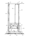
- FIG. 2 is a front view of the transfer device 2
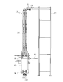
- FIG. 3 is a side view. Details of the transfer device 2 will be described with reference to FIGS.
- symbol 40 in FIG.2, 3 has shown the rectangular panel 40 of the cultivation unit transferred by the transfer apparatus 2 (the plant contained in a cultivation unit is not shown in figure).
- the transfer device 2 is configured using a stacker crane. Specifically, it includes a frame 21, a travel rail 22, a travel guide 23, a travel platform 24, a lift guide 25, a lift belt 26, a transfer unit 28, and a power distribution unit 29.
- the frame 21 is fixed so as to be arranged in the left-right direction with the foremost strut of the cultivation shelf 1, a plurality of struts, a rear strut fixed at an appropriate position behind the strut, and an upper portion between the struts It is comprised with the horizontal beam connected in the left-right direction and the vertical beam which connects between the front and back support
- the plurality of struts are erected so as to be respectively positioned in the gaps between the plurality of multistage shelves constituting the cultivation shelf 1, and the horizontal beams are provided so as to straddle the cultivation shelf 1 in the left-right direction.
- the vertical beam of the frame 21 extends an appropriate length in the forward direction.
- the traveling guide 23 and the power distribution unit 29 are installed on the extending end of the vertical beam.
- a traveling rail 22 is laid on the floor so as to be parallel to the traveling guide 23.
- a traveling table 24 is supported on the traveling rail 22 via drive wheels.
- the traveling table 24 is provided with two upright lifting guides 25, a lifting belt (chain) 26, and a transfer unit 28.
- the two raising / lowering guides 25 are fixed to the traveling platform 24 and connected at the upper part, and the connecting part is supported by the traveling guide 23 via a guide wheel.
- the traveling table 24 moves in the left-right direction while being guided by the traveling rail 22 and the traveling guide 23 by rotating driving wheels by the driving force of a traveling motor 241 (see FIG. 4) provided on the traveling table 24.
- the transfer unit 28 includes a first frame that is horizontally supported between two lift guides 25 via a guide wheel, and a second frame that is movably supported in the front-rear direction with respect to the frame inside the frame. And a chuck unit fixed in the frame.
- the first frame is connected to one end of the elevating belt 26.
- the elevating belt 26 extends upward from the transfer unit 28 and is connected to an elevating motor 251 (see FIG. 4) that is folded back at the upper part of the elevating guide 25 and installed on the traveling platform 24.
- the transfer unit 28 is moved up and down by being guided by the lifting guide 25 as a whole when the lifting belt 26 is sent by the lifting motor 251 and the first frame is moved up and down.
- the chuck unit fixed to the second frame can grip the edge of the rectangular panel 40 of the cultivation unit, and the second frame moves in the front-rear direction, so that both can move in the front-rear direction. is there. Thereby, as for the rectangular panel 40, the edge part of the back side can reach
- the transfer unit 28 includes a camera unit 27 on the upper part of the second frame.
- the camera unit 27 includes a camera 271 directed downward to include the cultivation unit held by the chuck unit in the imaging range.
- the number of cameras 271 is not limited to one, and a plurality of cameras 271 may be provided for one transfer unit 28.
- the power distribution unit 29 accommodates cables for supplying power and signals to the components installed in the traveling platform 24.
- the lifting guide 25 is provided with cables for supplying electric power and signals to the components of the transfer device 2, so that the transfer unit can be placed at any position on the travel rail 22.
- a connection mechanism is provided so that the cable contacts the power distribution unit 29 regardless of the height of the cable 28.
- one transfer device 2 is provided in front of the cultivation shelf 1, and one transfer device 2 is also provided on the rear side.
- the two transfer devices 2 are provided so as to face each other with the cultivation shelf 1 sandwiched in the front-rear direction, and thereby the cultivation system 100 is configured.
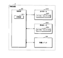
- FIG. 4 is a block diagram illustrating a configuration of the control unit 30 of the transfer apparatus 2.
- the control unit 30 uses a PLC (Programmable Logic Controller).
- the control unit 30 includes a storage unit 301 and is connected to the travel motor 241, the lifting motor 251, and the transfer unit 28.
- the control unit 30 outputs control signals to the traveling motor 241 and the lifting motor 251 and inputs output pulses from the rotary encoders 242 and 252 attached to the output shafts of the motors.
- the speed reducer is attached to the motors 241 and 251
- the rotary encoders 242 and 252 may be attached to the output shaft of the speed reducer.
- the control unit 30 can specify the position of the traveling platform 24 on the traveling rail 22 and the position of the transfer unit 28 relative to the lifting guide 25 by measuring the number of output pulses from the rotary encoders 242 and 252. Based on the position information, the control unit 30 controls the traveling of the traveling platform 24 and the lifting / lowering of the transfer unit 28, that is, the movement of the cultivation unit in the left-right direction and the up-down direction.
- the storage unit 301 uses a non-volatile storage medium such as a flash memory, and can be read and written from the control unit 30.
- the storage unit 301 stores in advance the positions at which the transfer unit 28 should stop with respect to each storage unit of the cultivation shelf 1 (the travel stop position of the travel platform 24 and the lift stop position of the transfer unit 28).
- the position to be stopped is stored as the number of output pulses of the rotary encoder 242 of the traveling motor 241 starting from the initial position of the traveling platform 24 (Home ⁇ Position (origin), for example, the left end on the traveling rail 22). .
- the elevation is stored as the number of output pulses of the rotary encoder 252 of the elevation motor 251 starting from the initial position (and the lower limit in the height direction) of the transfer unit 28.
- the control unit 30 counts the number of output pulses during traveling and during ascending / descending, and when the number matches the number of output pulses stored in the storage unit 301 as the stop position, the position is specified. Stop.
- the control unit 30 causes the transfer device 2 on the front side to take in the cultivation unit placed in another place (not shown) into the transfer unit 28 and travel the traveling table 24 in the frontage direction (left and right direction) of the cultivation shelf 1. Then, the transfer unit 28 is moved up and down. And the transfer apparatus 2 stops the transfer unit 28 in the position corresponding to the predetermined
- the control unit 30 outputs a control signal for moving the cultivation unit, that is, the second frame in the front-rear direction (toward the rear) to the transfer unit 28, and both sides of the rectangular panel 40 of the cultivation unit. The side portion is placed along the guide rail 12.
- this cultivation unit placement process is performed on all the accommodation units of the cultivation shelf 1, for example, once or twice a day. Thereby, the cultivation unit placed in each storage unit is pushed back little by little, and reaches the end in 30 days from 20 days later.
- the transfer device 2 provided on the rear side, the process of taking out the cultivation units from all the accommodation units of the cultivation device 1 is performed once or twice a day under the control of the control unit 30.
- the rear transfer device 2 conveys the extracted cultivation unit to a mounting place corresponding to the next step (for example, harvesting).
- the cultivation system 100 of this indication a growth process is carried out without an operator's work from the part which the transfer equipment 2 of the front side takes in a cultivation unit to the next process which the transfer equipment 2 of the back side conveys.
- Fully automated when trouble occurs during the operation of the transfer device 2, the situation at the time when the trouble occurs must be inferred from the state of the cultivation system 100 at the time when the worker who detected the trouble has confirmed. .
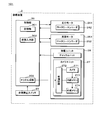
- FIG. 5 is a block diagram showing the configuration of the recording system 101 applied in the first embodiment.
- the control unit 30 includes a state input unit 302 and a trigger generation unit 303 in addition to the storage unit 301.
- the state input unit 302 is a signal input interface of the control unit 30 which is a PLC, and the trigger generation unit 303 generates a trigger signal using a clock and signal generation unit.
- the trigger generation unit 303 may execute processing in terms of software based on a program stored in the storage unit 301.
- the trigger signal generated by the trigger generation unit 303 is output toward the transfer unit 38.
- the state input unit 302 inputs signals from the traveling motor 241 and the lifting motor 251.
- the signal input by the state input unit 302 is a signal indicating a load, speed (acceleration), temperature, vibration, or the like of each of the traveling motor 241 and the lifting motor 251.
- the state input unit 302 may input a signal from the transfer unit 28.
- the signal input from the transfer unit 28 by the state input unit 302 is, for example, a signal for detecting that the chuck unit holds the rectangular panel 40 of the cultivation unit (for example, a signal corresponding to torque in the gripping mechanism).
- the state input unit 302 may input a signal from the emergency emergency stop switch 20 provided in the transfer device 2.
- the trigger generation unit 303 generates a trigger signal based on the signal input by the state input unit 302 from the travel motor 241, the lift motor 251, the transfer unit 28, or the emergency stop button 20. For example, the trigger generation unit 303 determines whether or not there is an overcurrent based on output signals from the overcurrent detection circuits of the traveling motor 241 and the lifting motor 251 and outputs a trigger signal when there is an overcurrent, that is, an overload. Further, the trigger generation unit 303 calculates speed or acceleration based on the frequency of the output pulse signals from the rotary encoders 242 and 252 and determines whether or not the speed or acceleration of the traveling platform 24 or the transfer unit is faster than a predetermined speed. If it is determined that the signal is fast, a trigger signal is output.
- the trigger generation unit 303 determines whether the temperature or the magnitude or frequency of vibration is within the safe use range of each motor 241 and 251 based on the signal level or frequency of the output signal from the temperature sensor or vibration sensor. A trigger signal is output when it is determined whether or not it is out of the use range.
- the trigger generation unit 303 When the trigger generation unit 303 inputs a grip detection signal from the chuck unit of the transfer unit 28, the trigger generation unit 303 inputs a monitor signal indicating an instruction content from the control unit 30 to the transfer unit 28.
- the trigger generation unit 303 outputs a trigger signal when the gripping mechanism detects that the gripping mechanism is not gripped even though the control unit 30 has instructed gripping to the chuck unit of the transfer unit 28. Output. In this case, the cultivation panel 40 is dropped.
- a trigger signal may also be output when an excessive torque is detected even though the gripping operation and the detachment operation are not supported. Also in this case, abnormalities such as catching and collision of the cultivation panel 40 are suspected.
- the trigger generation unit 303 When the signal from the emergency stop switch 20 is input, the trigger generation unit 303 outputs a trigger signal when the switch is pressed.
- the control unit 30 When the trigger signal is output from the trigger generation unit 303, that is, the control unit 30 detects an abnormality such as overcurrent, speed abnormality, temperature or vibration in the traveling motor 241 or the lifting motor 251 or the like. These detected contents may be stored in the storage unit 301 as log data so that they can be identified. When the emergency stop switch 20 is pressed, the control unit 30 stores the video data as described later and stops the operation of the transfer device 2. In addition, the control unit 30 may stop the operation of the transfer device 2 for safety when an abnormality is detected.
- an abnormality such as overcurrent, speed abnormality, temperature or vibration in the traveling motor 241 or the lifting motor 251 or the like.
- the control unit 30 stores the video data as described later and stops the operation of the transfer device 2. In addition, the control unit 30 may stop the operation of the transfer device 2 for safety when an abnormality is detected.
- the camera unit 27 includes a control circuit 272, an internal memory 273, and an external memory 274 in addition to the camera 271.
- the camera 271 uses a CCD (Charge Coupled Device) camera, for example, and outputs a video signal obtained by imaging the lower part from the upper part of the second frame provided with the chuck unit as described above.
- the internal memory 273 uses a volatile memory such as a DRAM (Dynamic Random Access Memory), for example, and sequentially stores video signals output from the camera 271 as video data. At this time, the internal memory 273 overwrites old video data with new video data in order. For example, the cultivation system 100 only needs to be able to store images for 6 to 12 hours.
- the external memory 274 is preferably detachable from the camera unit 27, for example, an SD memory card. By using a detachable small memory, it becomes easy to reproduce and confirm video data described later.
- the control circuit 272 includes a terminal for inputting a trigger signal from the trigger generation unit 303 of the control unit 30 and a clock.
- the control circuit 272 includes a predetermined amount of video data stored in the internal memory 273.
- the video data for a predetermined time includes video data past the trigger signal input timing, and preferably includes video data after the input timing.
- the predetermined time is, for example, several tens of seconds to several minutes before and after the input timing.
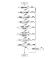
- FIG. 6 is a flowchart illustrating an example of a recording procedure by the recording system 101.
- the state input unit 302 of the control unit 30 inputs signals from all of the travel motor 241, the lift motor 251, the chuck unit of the transfer unit 28, and the emergency stop switch 20.
- the travel motor 241, the lift motor 251, the chuck unit of the transfer unit 28, and the emergency stop switch 20 inputs signals from all of the travel motor 241, the lift motor 251, the chuck unit of the transfer unit 28, and the emergency stop switch 20.
- the state input unit 302 of the control unit 30 inputs signals from all of the travel motor 241, the lift motor 251, the chuck unit of the transfer unit 28, and the emergency stop switch 20.
- the control unit 30 determines whether an overcurrent is detected as one of the trigger generation units 303 based on a signal input from the traveling motor 241 or the lifting motor 251 (step S1). When it is determined that no overcurrent is detected (S1: NO), the control unit 30 determines whether the traveling speed of the traveling platform 24 or the lifting / lowering speed of the transfer unit 28 is faster than a predetermined speed (step S2). . When it is determined that the speed is equal to or lower than the predetermined speed (S2: NO), the control unit 30 determines whether the traveling acceleration of the traveling base 24 or the vertical acceleration of the transfer unit 28 is faster than the predetermined acceleration (step). S3).
- the control unit 30 determines whether or not the temperature in the traveling motor 241 or the lifting motor 251 is higher than the predetermined temperature (step S4). When it is determined that the temperature is equal to or lower than the predetermined temperature (S4: NO), the control unit 30 determines whether the vibration frequency or the vibration frequency of the traveling motor 241 or the lifting motor 251 is higher than the predetermined number (step). S5). When it is determined that the number is less than or equal to the predetermined number (S5: NO), the control unit 30 determines whether or not the torque is less than the first predetermined value despite instructing the chuck unit 28 to perform gripping (Step S5). S6).
- the control unit 30 determines whether the torque is larger than the second predetermined value and excessive (step S7). ). When the torque is below the second predetermined value and is caught and no collision is suspected (S7: NO), the control unit 30 determines whether or not the emergency stop switch 20 is pressed (step S8). When it is determined that the emergency stop switch 20 has not been pressed (S8: NO), the control unit 30 ends the process as it is. In this case, the control unit 30 may sequentially execute the processes from step S1 again after a predetermined standby time has elapsed.
- control unit 30 If YES in any one of the determination processes in steps S1-S8 (S1-S8: YES), the control unit 30 outputs a trigger signal as the trigger generation unit 303, whereby the camera unit 27 The video data for a predetermined time is stored (step S9), and the process is terminated.
- the cause and progress of the trouble that occurred in the following cases can be left as an image.
- the video data captured by the camera 271 directed below the transfer unit 28 is triggered by an overcurrent flowing due to an increase in the load on the traveling motor 241 or the lifting motor 251. 274 is stored.
- the worker who has recognized the occurrence of the trouble takes out the external memory 274, plays back the stored video data on another video playback device, and confirms this, so that what happened at the time of the trouble can be easily performed. I can grasp it.
- the video data is saved, so the external memory 274 can be taken out and played back to check the situation at the time of the trouble. Is easy.
- the operator can confirm the presence / absence of a foreign object, and the labor required for estimating the cause of the trouble can be reduced. It is.
- the trigger generation unit 303 outputs a trigger signal when the torque from the chuck unit when the gripping operation or the detachment operation is instructed by the control signal to the transfer unit 28 is excessive or small. Whether the trigger generation unit 303 outputs the trigger signal by comparing the pattern of the timing of the control signal from the control unit 30 and the timing of the change in the signal level of the torque signal with the pattern when an abnormality (falling) occurs. May be determined.
- FIG. 7 is a block diagram showing the configuration of the recording system 101 applied in the second embodiment.
- the control unit 30 includes a storage unit 301, a state input unit 302, a trigger generation unit 303, an internal memory 304, and an external memory 305. Since the state input unit 302 and the trigger generation unit 303 operate in the same manner as the state input unit 302 and the trigger generation unit 303 in the first embodiment, detailed description thereof is omitted.
- the video signal captured by the camera 271 is output to the control unit 30 and stored in the internal memory 304 of the control unit 30. Therefore, the trigger generation unit 303 does not output a trigger signal toward the transfer unit 28.
- the transfer unit 28 includes the camera 271, but does not need to include an internal memory for storing a video signal output from the camera 271 and a removable external memory.
- the camera 271 outputs a video signal to the control unit 30.
- the internal memory 304 of the control unit 30 uses a volatile memory such as a DRAM, takes in the video signal output from the camera 271 and sequentially stores it as video data. Furthermore, the internal memory 304 stores log data of control contents for the traveling motor 241, the lifting motor 251 and the transfer unit 28 by the control unit 30 sequentially and in synchronization with video data together with a time stamp obtained based on the clock.
- video data for example, the video data may be divided at predetermined timings such as 10 seconds and stored together with the time stamp, or the time stamp may be multiplexed and stored in the video data.
- the log data of the control content is, for example, travel position information (number of output pulses) or travel stop position for the control of the travel motor 241, and lift position information (number of output pulses) for the control of the lift motor 251, Or it is a raising / lowering stop position.
- the log data related to the control for the transfer unit 28 is, for example, a signal level of a control signal (command) to the transfer unit 28 and a sampling of a torque signal indicating whether the panel is held.
- the external memory 305 of the control unit 30 is preferably detachable from the control unit 30, for example, an SD memory card.
- an SD memory card By using a detachable small memory as the external memory 305, it becomes easy to reproduce and confirm video data described later.
- the control unit 30 outputs log data and video data for a predetermined time from video data stored together with log data in the internal memory 304 based on the trigger signal output from the trigger generation unit 303. It is stored in the external memory 305 together with the time stamp.
- the log data and video data for a predetermined time include data that is past the trigger output timing, and preferably includes data after the trigger output timing.
- the predetermined time is, for example, several tens of seconds to several minutes before and after the trigger output timing.
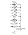
- FIG. 8 is a flowchart showing an example of a recording procedure by the recording system 101 according to the second embodiment.
- steps S1-S8 are YES (S1-S8: YES)
- control unit 30 outputs a trigger signal as trigger generation unit 303.
- the video data and log data are saved (step S10), and the process ends.
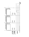
- FIG. 9 is a schematic diagram showing a synchronization image of log data and video data stored in the second embodiment.
- a time axis is shown from the left to the right in FIG. FIG. 9 shows that the video data, the position of the transfer unit 28 reproduced by the log data, and the control contents are synchronized.
- FIG. 7 data that can reproduce the control content (movement and operation of the transfer unit 28) and what has happened in the transfer unit 28 at that time are grasped.
- the cause and progress of the trouble can be left as an image, and the position and operation of the transfer device 2 corresponding to each time point can be reproduced. Can be reduced.
- the camera unit 27 is not mounted on the transfer unit 28, and the video signal output from the camera 271 is captured and stored on the control unit 30 side.
- the same camera unit 27 as that of the first embodiment is used, the control content information of the control unit 30 is output to the camera unit 27, and the log data and the video data of the control content are stored in the external memory 274 in the camera unit 27. You may comprise.
- FIG. 10 is a block diagram showing the configuration of the recording system 101 applied in the third embodiment.
- the control unit 30 includes a storage unit 301, a state input unit 302, a trigger generation unit 303, an internal memory 304, and a communication unit 306. Since the state input unit 302 and the trigger generation unit 303 operate in the same manner as the state input unit 302 and the trigger generation unit 303 in the first embodiment, detailed description thereof is omitted.
- a video signal captured by the camera 271 is output to the control unit 30 and stored as video data in the internal memory 304 of the control unit 30. Therefore, the trigger generation unit 303 does not output a trigger signal toward the transfer unit 28.
- the cultivation system 100 according to the third embodiment includes an external storage device 5 that is a device different from the transfer device 2.
- the transfer unit 28 includes the camera 271, but does not need to include an internal memory for storing a video signal output from the camera 271 and a removable external memory.
- the camera 271 outputs a video signal to the control unit 30.
- the internal memory 304 of the control unit 30 uses a volatile memory such as a DRAM, takes in the video signal output from the camera 271 and sequentially stores it as video data.
- the internal memory 304 sequentially synchronizes the log data of the control contents for the traveling motor 241, the lifting motor 251 and the transfer unit 28 by the control unit 30 with the video data together with the time stamp obtained based on the clock as in the second embodiment. It may be memorized.
- the communication unit 306 of the control unit 30 uses a wireless communication device such as Wi-Fi or a wired communication device such as Ethernet (registered trademark) for communication connection to an in-plant LAN disposed in a plant factory, or external Direct communication connection with the storage device 5 is possible.
- the communication unit 306 may use Bluetooth (registered trademark) as long as the control unit 30 can communicate with the external storage device 5.
- the control unit 30 Based on the trigger signal output from the trigger generation unit 303, the control unit 30 outputs video data for a predetermined time, together with a time stamp, from video data stored together with log data in the internal memory 304.
- the data is transmitted from the communication unit 306 to the external storage device 5.
- the video data for a predetermined time includes data past the trigger output timing, and preferably includes data after the trigger output timing.
- the predetermined time is, for example, several tens of seconds to several minutes before and after the trigger output timing.
- the control unit 30 may transmit the log data for a predetermined time corresponding to the video data from the communication unit 306. Good.
- the external storage device 5 uses a PC (Personal Computer) installed in a space of the plant factory where the cultivation system 100 is installed and in a space different from the cultivation system 100.
- the external storage device 5 may also be a PC used as a monitoring device used by an operator in the cultivation system 100.
- the external storage device 5 is not limited to this, and may be a server device that exists outside the plant factory.
- the external storage device 5 includes a CPU (Central Processing Unit) 50, a communication unit 51, a memory 52, and an output unit 53.
- the output unit 53 is connected to a monitor 54.
- the communication unit 51 can use a communication device based on a communication standard corresponding to the communication unit 306 of the control unit 30 to establish communication connection with a factory LAN.
- the memory 52 uses a non-volatile storage device such as a flash memory or a hard disk.
- the output unit 53 reproduces and outputs a video signal based on the video data stored in the storage unit 52 to the monitor 54 under the control of the CPU 50.
- the CPU 50 of the external storage device 5 detects that video data is transmitted from the control unit 30 by the communication unit 51, receives the transmitted video data, and stores it in the memory 52 that stores it together with a time stamp.
- the CPU 50 receives a playback instruction through an operation unit (not shown)
- the CPU 50 can read the video data from the memory 52 and play it on the monitor 54 from the output unit 53.
- the trigger generation unit 303 of the control unit 30 generates a trigger signal based on a signal input from the traveling motor 241 and the lifting / lowering motor 251, the transfer unit 28, or the emergency stop button 20.
- a trigger signal is output in the previous stage.
- the trigger generation unit 303 determines that the temperature, the magnitude of vibration, or the frequency of the motors 241 and 251 is safe from the signal level or frequency of the output signal from the temperature sensor or vibration sensor. It was determined whether it was within the range of use.
- the trigger generation unit 303 determines whether or not the change is moving outside the use range even if each motor 241 and 251 is within the safe use range, and an abnormality is predicted. To do.
- the prediction determination may be performed, for example, based on whether a threshold value on the safe side of the abnormal temperature range is exceeded.
- the trigger generation unit 303 has a second threshold value at which the motor temperature corresponding to the signal level of the signal output from the temperature sensors of the motors 241 and 251 is lower than the first threshold value related to the presence or absence of abnormality. It is determined whether or not the temperature is (second predetermined temperature) or higher, and when it is determined that the temperature is higher than or equal to the second threshold value, it is determined that a trouble is predicted and a trigger signal is output.
- the processing as the prediction unit of the trigger generation unit 303 of Embodiment 3 may be as follows.
- the trigger generation unit 303 stores a change with time of signal values indicated by signals input from the traveling motor 241 and the lifting motor 251 in addition to the determination with respect to the threshold value, and the tendency of the change with time is toward an abnormal range.
- the occurrence of trouble may be predicted by determining whether or not there is.
- FIG. 11 is a flowchart illustrating an example of a recording procedure by the recording system 101 according to the third embodiment.
- the control unit 30 determines, as the trigger generation unit 303, that the temperature is equal to or lower than a predetermined temperature (first predetermined temperature) (S4: NO), the control unit 30 performs the traveling motor 241 or the lifting motor 251. It is determined whether the temperature at is higher than a second predetermined temperature lower than the first predetermined temperature (step S45).
- the second predetermined temperature corresponds to the second threshold value described above.
- the control unit 30 determines whether the vibration frequency or the vibration frequency of the traveling motor 241 or the lifting motor 251 is higher than the first predetermined number. (S5). When it is determined that the frequency is equal to or less than the first predetermined number (S5: NO), the control unit 30 determines whether the vibration frequency or the vibration frequency is higher than the second predetermined number (step S56). When it is determined that it is less than or equal to the second predetermined number (S56: NO), the control unit 30 determines whether or not the torque is less than the first predetermined value in spite of instructing the chuck unit 28 to perform gripping. (S6).
- the control unit 30 determines whether or not other abnormality is predicted (step S11). When it is determined that no abnormality is predicted (S11: NO), the process is terminated. Whether or not other abnormalities are predicted is determined based on, for example, whether or not the tendency of change is toward the abnormal range based on the storage of the temporal change as described above.
- control unit 30 triggers when any one of steps S45 and S56 is YES (S1-S8, S45, S56 or S11: YES). Output a signal.
- the video data is stored (S9), and the process is terminated.
- the log data may be stored together as described above.
- the storage location of the video data is the external storage device 5 instead of the memory inside the camera unit 27 in the first embodiment. Therefore, before heading to the installation location of the cultivation system 100, the operator can estimate the cause of the trouble that has occurred in the transfer device 2 of the cultivation system 100.
- the trigger generation unit 303 also operates as a prediction unit that predicts the occurrence of trouble in the transfer device 2.
- the operator can grasp the sign of the trouble occurrence from a remote location by sequentially storing the video data in the external storage device 5. This increases the possibility that troubles can be prevented from occurring, and the operation can be continued without stopping the cultivation system 100.
- the camera unit 27 is not mounted on the transfer unit 28, the video signal output from the camera 271 is captured on the control unit 30 side, and the video data is transmitted by the communication unit 306 provided in the control unit 30. It was.
- the camera unit 27 similar to that of the first embodiment may be provided with a communication unit, and the video data read from the internal memory by the communication unit may be transmitted to the external storage device 5.
- the recording system 101 is applied to the cultivation system 100 that realizes a large-scale plant factory.
- the same configuration can also be applied to a cultivation system including a transfer device used in a small plant factory. Trouble occurs by installing a camera and storing video data with triggers based on those signals if the control signal for controlling the transfer device, the signal indicating the status of the transfer device, etc. can be captured. It is possible to make it possible to reproduce the situation or the situation where trouble is expected to occur.
Landscapes
- Engineering & Computer Science (AREA)
- Mechanical Engineering (AREA)
- Life Sciences & Earth Sciences (AREA)
- Environmental Sciences (AREA)
- Warehouses Or Storage Devices (AREA)
- Hydroponics (AREA)
- Cultivation Receptacles Or Flower-Pots, Or Pots For Seedlings (AREA)
Abstract
トラブル発生時の復旧を迅速化させ、効率のよい自動運転を達成させる移載装置、及び該移載装置を用いた栽培システムを提供する。縦横に並設された複数の収容部を有する収容棚の間口方向に沿って移動し、高さ方向に沿って昇降する移載ユニットを有し、移載ユニットにより被移載物を前記収容部に対し移載する移載装置において、移載ユニット内に設けられているカメラと、カメラから出力される映像を逐次記憶する第1のメモリと、映像を記憶する第2のメモリと、移載装置の動作の状態を示す信号を入力する状態入力部とを備え、状態入力部により入力した信号をトリガとして第1のメモリに記憶される映像の内、トリガのタイミング以前及び以降にカメラにより撮影された所定時間分の映像を第2のメモリへ保存する。
Description
本発明は、例えば植物工場で用いられる栽培ユニットを移載する移載装置及び該移載装置を用いる栽培システムに関する。
生育環境を制御して植物を育てる植物工場が規模の大小を問わず増加している。その中でも大規模の植物工場では、播種、芽出し、緑化、苗選別、育苗、苗移植、生育、及び収穫等の栽培の工程における作業の自動化が進められている。植物工場で栽培される野菜は、天候に左右されない安定供給が可能であること、最適化された培養材で栽培されることによる栄養価の高さ、虫害がないことによる無農薬栽培が可能であることなどの優れた点を有する。その一方で、温度及び湿度の維持、並びに光源等に掛かる光熱費によるコスト高の懸念がある。コストを抑制するためには、人的コストを抑えて高効率化することが重要である。
特許文献1及び特許文献2には、植物を収容した栽培容器を高さ方向に数段分載置可能な棚を設けて栽培容器を多数載置し、栽培容器に向けて光源からの光を照射させる栽培システムにおいて、各栽培容器を適切な位置へ載置させる制御を行なうことが開示されている。栽培容器を棚における最適な位置に載置するために、栽培容器における植物の生育状況の目視確認を可能とすべくモニタカメラを用いることが開示されている。モニタカメラを例えば栽培容器を移動させる移動装置に設けるなどして、そのモニタカメラから出力される映像を係員が確認し、確認した結果に応じて栽培容器の移動、取り出しを行なうように係員が移動装置を動作させる。
人的コストを抑えるためには完全な自動運転(無人運転)が望ましい。特許文献1、2のように生育状況を係員が目視できるようにモニタカメラを設けることで、作業の効率化を図ることはできるが、生育状況を係員が目視確認して生育状況の良し悪しを判定して動作を指示しなければ次の段階へ進めず、自動運転は達成されない。
本発明は斯かる事情に鑑みてなされたものであり、トラブル発生時の復旧を迅速化させ、効率のよい自動運転を達成させる移載装置、及び該移載装置を用いた栽培システムを提供することを目的とする。
本発明に係る移載装置は、縦横に並設された複数の収容部を有する収容棚の間口方向に沿って移動し、高さ方向に沿って昇降する移載ユニットを有し、該移載ユニットにより被移載物を前記収容部に対し移載する移載装置において、前記移載ユニット内に設けられているカメラと、該カメラから出力される映像を逐次記憶する第1のメモリと、前記映像を記憶する第2のメモリと、該移載装置の動作の状態を示す信号を入力する状態入力部とを備え、前記状態入力部により入力した信号をトリガとして前記第1のメモリに記憶される映像の内、前記トリガのタイミング以前及び以降に前記カメラにより撮影された所定時間分の映像を第2のメモリへ保存する。
本発明に係る移載装置は、前記状態入力部は、前記移載ユニットを間口方向及び高さ方向に移動させるモータの負荷、速度、加速度、温度、又は振動の状態を示す信号を入力し、前記トリガは、入力された信号の信号レベルの所定値との比較結果又は該信号が示す状態の変化である。
本発明に係る移載装置は、前記移載ユニットの移動及び動作を制御する制御部を備え、前記状態入力部は、前記移載ユニット内の被移載物の有無を示す信号を該移載ユニットから入力し、前記制御部は、前記移載ユニットに対する移動又は制御内容及び前記被移載物の有無の信号に基づき、前記トリガを生成する。
本発明に係る移載装置は、前記状態入力部は、該移載装置の非常停止スイッチの状態を示す信号を入力し、該状態が、非常停止がなされたことを示す場合に、前記トリガが生成される。
本発明に係る移載装置は、前記カメラ、第1のメモリ及び第2のメモリは、前記移載ユニットに設けられたカメラユニットに設けられており、該カメラユニットは、前記トリガを入力して該トリガのタイミング以前及び以降に該カメラユニット内のカメラにより撮影された所定時間分の映像を第2のメモリへ保存する。
本発明に係る移載装置は、前記第1のメモリ及び第2のメモリは、前記制御部が備え、該制御部は、前記カメラから出力される映像を入力し、前記移載ユニットに対する移動又は制御内容を示すログデータと共に時間情報を対応付けて前記第1のメモリに逐次記憶する。
本発明に係る移載装置は、前記第2のメモリは、該移載装置に対し着脱可能に備えられている不揮発性メモリである。
本発明に係る移載装置は、無線又は有線により情報を送信する通信部を更に備え、前記第2のメモリは、該移載装置外の外部記憶装置内に設けられており、前記通信部は、前記所定時間分の映像を前記第2のメモリへ向けて送信する。
本発明に係る栽培システムは、植物及び該植物の培地を含む栽培ユニットを収容する収容部を縦横に複数有する栽培棚と、該栽培棚の間口方向に沿って縦横に移動する移載ユニットを有し、該移載ユニットにより前記栽培ユニットを複数の前記収容部夫々に対し移載する移載装置とを含む栽培システムにおいて、前記移載装置は、前記移載ユニット内に設けられているカメラと、該カメラから出力される映像を逐次記憶する第1のメモリと、前記映像を記憶する第2のメモリと、該移載装置の動作の状態を示す信号を入力する状態入力部とを備え、前記状態入力部により入力した信号をトリガとして前記第1のメモリに記憶される映像の内、前記トリガのタイミング以前及び以降に前記カメラにより撮影された所定時間分の映像を第2のメモリへ保存する。
本発明では、移載装置の動作の状態がトラブル発生を示す場合、又はトラブル発生が予測できる状態である場合に、これをトリガに、移動及び昇降する移載ユニットに設けられたカメラにて撮影された映像を残すことができる。これにより、作業者が事後的に映像データを再生確認することでトラブルの発生時の状況の把握、再現が容易であり、移載装置の運転復旧も迅速化させることができる。
本発明では、移載装置の動作の状態を示す信号として、移載ユニットの移動に用いられるモータの負荷、速度、加速度、温度、又は振動の状態を示す信号を用いる。これにより、モータの過負荷、速度超、振動数の過大等をトリガにトラブル発生の状況を映像で記憶しておくことができる。
本発明では、移載ユニットへの制御内容(被移載物を取り込もうとしているか、また被移載物を移載先へ載置しようとしているのか)と、移載ユニットで検知できる被移載物の有無等の状態との整合がとれないことをトリガにトラブル発生の状況を映像で記憶しておくことができる。
本発明では、非常停止スイッチがオン状態となった場合に映像データが保存されるから、非常停止したときの移載装置の動作を映像として再現することが可能になる。
本発明では、カメラ素子を内蔵する既存のカメラユニット、例えば汎用のデジタルカメラの内部メモリ及び着脱可能な外部メモリを使用して移載装置の動作の映像を再現することが可能である。
本発明では、移載装置及び移載ユニットの移動及び動作を制御する制御部側に設けられたメモリに映像データが保存される。制御部は移載装置の移載ユニットへの移動又は制御内容を映像データと共に時間情報と対応付けることが容易である。なお制御内容をカメラ側へ向けて出力し、カメラ側で映像データと共に記憶するようにしてもよい。
本発明では、着脱可能なメモリを保存に用いることで映像データの再生、確認が容易になる。
本発明では、通信部により映像が送信され、移載装置外の装置のメモリに映像データが保存される。これにより、移載装置にてトラブルが発生した場合に稼働現場から離れた場所で、トラブル発生状況を再生確認することができ、作業者は移載装置で発生しているトラブルの原因の推定が可能である。
本発明による場合、トラブル発生後に事象の再現、又はトラブルの予測を可能とする映像が保存されるから、仮にトラブルが発生した場合の運転復旧も迅速化させることが可能であり、効率の良い自動運転が達成できる。
本発明をその実施の形態を示す図面を参照して具体的に説明する。なお、以下に説明する実施の形態では、本発明に係る移載装置を植物工場における植物及び培地を含む栽培ユニットの移載に適用した例を挙げて説明する。
本実施の形態にて植物工場は、栽培の各工程の内、苗移植後の生育工程において、植物の苗が移植された栽培ユニットを収容する栽培棚と、該栽培棚に対し栽培ユニットを自動的に移載する装置とを含む栽培システムを用いる。
図1は、本実施の形態における栽培システム100の模式斜視図である。以下の説明では、図1中の矢符により示す上下、左右及び前後を使用する。本実施の形態における栽培システム100は、栽培棚1及び移載装置2を含む。栽培棚1は、栽培ユニットを上下方向に複数収容可能な多段棚を左右方向に複数並設して構成される。実施の形態1において栽培ユニットは、複数の孔が縦横に設けられた矩形状の栽培パネルのその各孔に、栽培対象の植物の苗が植えられた培地が埋められている状態のものである。移載装置2は、栽培棚1の間口方向(左右方向)及び高さ方向(上下方向)に移動する移載ユニットを有し、該移載ユニットを用いて他所から栽培ユニットを栽培棚1の各収容部へ載置又は各収容部から取り出す装置である。
栽培棚1は、骨組みとなるフレーム11と、栽培ユニットを受けるガイドレール12と、収容している各栽培ユニットの下部に、常時供給される培養液の流れを形成するための樋13と、該樋13を支持する樋受14及び支持部15とを備える。フレーム11をガイドレール12、樋13、及び樋受14によって仕切ることにより栽培棚1の各収容部を構成している。
フレーム11は、左右一対の支柱の上部を横梁で連結してなる門型のフレーム部材を前後方向に複数並べ、これらのフレーム部材の上部を縦梁により連結して構成されている。そしてガイドレール12は、これらのフレーム部材を前後方向に連結するようにして床面に対して平行に、左右の支柱夫々の内側に設けられている。なおガイドレール12は、上下方向に所定の間隔を開けて複数(図1では11組)設けられており、しかも左右で同じ高さとなるように設けられている。
樋受14は、短冊状の板材をなし、フレーム部材の支柱間に左右方向に架け渡されている。樋受14は、左右同じ高さに設けられている複数のガイドレール12の下面に対して夫々位置決めされている。
樋13は、断面コの字状の形状を有し、例えば樹脂製である。樋13は樋受14にフレーム11の前後方向の全長に亘って、床面に略平行に架け渡されている。なお樋13は、フレーム11から前方及び後方に適長突き出すように架設されている。
支持部15は、フレーム11の最前方の支柱から前方へ突き出るように設けられており、樋13の前方の突き出し部を支持している。同様にして後方側においても支持部15(図示せず)が最後方の支柱から後方に突き出るように設けられており、樋13の後方の突き出し部を支持している。
栽培棚1は、上述のようなフレーム11、ガイドレール12、樋13、樋受14及び支持部15を含む1組の多段棚を並設して構成される。1組の多段棚の大きさは例えば、幅(左右方向)が1400mm、高さ(上下方向)が7500mm、奥行き(前後方向)が20000mmである。栽培棚1は、このような多段棚を、所定間隔を設けて例えば20組、幅36000mmに亘って並設されて構成される。大きさは例示であって幅、高さ及び奥行き夫々、植物工場の規模に応じて多様であってよい。なお栽培棚1が設置される植物工場の床面は、後方向に向けて僅かな傾斜を有しており、これにより樋13における培養液の流れを促すようにしてあるとよい。
更に栽培棚1の各収容部の内部には、光源が設けられている(図示せず)。なお光源は、白色発光ダイオード又は蛍光灯を下方に向けて吊り下げて構成される。
次に、このような栽培棚1の各収容部に対して栽培ユニットを移載する移載装置2について説明する。図2は、移載装置2の正面図であり、図3は側面図である。図1-図3を参照して移載装置2について詳細を説明する。なお図2,3における符号40は、移載装置2により移載される栽培ユニットの矩形状のパネル40を示している(栽培ユニットに含まれる植物は図示せず)。
移載装置2は、スタッカークレーンを用いて構成される。具体的には、フレーム21、走行レール22、走行ガイド23、走行台24、昇降ガイド25、昇降ベルト26、移載ユニット28、及び配電部29を備える。
フレーム21は、栽培棚1の最も手前の支柱と左右方向に並ぶように固定されて複数の支柱と、該支柱よりも後方の適正な位置に固定された後方側の支柱と、支柱間を上部で左右方向に連結する横梁と、前後の支柱間を連結する縦梁とで構成される。複数の支柱は、栽培棚1を構成する複数の多段棚間の隙間に各々位置するように立設されており、横梁は栽培棚1を左右方向に跨ぐように設けられている。そしてフレーム21の縦梁は、前方向へ向けて適長延出している。走行ガイド23及び配電部29はこの縦梁の延出端に架設されている。
床面には走行レール22が、走行ガイド23に平行となるようにして敷設されている。走行レール22上には、駆動車輪を介して走行台24が支持されている。走行台24には、直立する2本の昇降ガイド25、昇降ベルト(チェーン)26、及び移載ユニット28が設置されている。2本の昇降ガイド25は、走行台24状に固定されていると共に上部で連結されており、該連結部は走行ガイド23にガイド輪を介して支持されている。走行台24は、走行台24に設けられている走行モータ241(図4参照)の駆動力によって駆動車輪を回転させることにより、走行レール22及び走行ガイド23に案内されて左右方向に移動する。
移載ユニット28は、2本の昇降ガイド25間にガイド輪を介して横架支持された第1のフレームと、該フレームの内側で該フレームに対して前後方向に可動に支持された第2のフレームと、該フレーム内に固設されたチャックユニットとを含む。第1のフレームは、昇降ベルト26の一端に連結されている。昇降ベルト26は、移載ユニット28から上方に延び、昇降ガイド25の上部で折り返されて走行台24に設置された昇降モータ251(図4参照)に連結されている。移載ユニット28は昇降モータ251によって昇降ベルト26が送られ、第1のフレームが昇降することで、全体として昇降ガイド25に案内されて上下方向に移動する。第2のフレームに固設されたチャックユニットは、栽培ユニットの矩形状パネル40の縁部を把持することができ、第2フレームが前後方向に移動することで、共に前後方向の移動が可能である。これにより矩形状パネル40は、その後方側の縁部が栽培棚1のガイドレール12へ到達し得る。更に移載ユニット28は、第2のフレームの上部にカメラユニット27を備える。該カメラユニット27は、チャックユニットに把持された栽培ユニットを撮影範囲に含むべく下方に向けたカメラ271を含む。なおカメラ271は1つに限らず、1つの移載ユニット28に対して複数備えられてもよい。
配電部29は、走行台24に設置されている各構成部への電力及び信号を供給するケーブルを収容している。昇降ガイド25には、移載装置2の各構成部に電力及び信号を供給する各ケーブルが配設されており、走行台24が走行レール22上のいずれの位置にあっても、移載ユニット28がいずれの高さにあっても前記ケーブルが配電部29と接触するように接続機構が設けてある。
移載装置2は、図1に示すように栽培棚1の前方に1つ設けられる他、後方側にも1つ設けられている。2つの移載装置2は、栽培棚1を前後方向に挟んで対向するように設けられ、これにより栽培システム100が構成される。
このように構成される栽培システム100における2つの移載装置2の動作は、各々の走行台24に設けられた制御部30により制御される。移載装置2は図1-図3に示すように、走行台24上に制御部30を備えている。図4は、移載装置2の制御部30の構成を示すブロック図である。制御部30はPLC(Programmable Logic Controller)を用いる。制御部30は、記憶部301を備え、走行モータ241、昇降モータ251、及び移載ユニット28と接続されている。
制御部30は走行モータ241、昇降モータ251へ制御信号を出力すると共に、各モータの出力軸に取り付けられているロータリーエンコーダ242,252からの出力パルスを入力する。モータ241,251に減速機が取り付けられている場合には、ロータリーエンコーダ242,252は減速機の出力軸に取り付けられていてもよい。制御部30は、各ロータリーエンコーダ242,252からの出力パルス数を計測することによって走行台24の走行レール22上の位置、移載ユニット28の昇降ガイド25に対する位置を特定することができる。制御部30は、その位置情報に基づいて走行台24の走行及び移載ユニット28の昇降、即ち栽培ユニットの左右方向及び上下方向における移動を制御する。
記憶部301は、フラッシュメモリ等の不揮発性の記憶媒体を用い、制御部30から読み書きが可能である。記憶部301には予め、栽培棚1の各収容部に対して移載ユニット28が停止すべき位置(走行台24の走行停止位置、及び移載ユニット28の昇降停止位置)が記憶されてある。なおこの停止すべき位置は、走行台24の初期位置(Home Position(原点)、例えば走行レール22上の左端)を開始地点とした走行モータ241のロータリーエンコーダ242の出力パルス数として記憶されている。昇降についても同様に、移載ユニット28の初期位置(及び高さ方向の下限)を開始地点とした昇降モータ251のロータリーエンコーダ252の出力パルス数として記憶されている。制御部30は、走行中及び昇降中の各々の出力パルス数を計数し、記憶部301に停止位置として記憶されている出力パルス数に合致した場合にその位置を特定し、移載ユニット28を停止させる。
制御部30によってまず、前方側の移載装置2が、図示しない他所に載置されている栽培ユニットを移載ユニット28に取り込み、走行台24を栽培棚1の間口方向(左右方向)に走行させつつ、移載ユニット28を昇降させる。そして移載装置2は、栽培棚1の所定の収容部に対応する位置で移載ユニット28を停止させる。停止位置にて制御部30は、移載ユニット28に対し、栽培ユニット即ち第2のフレームを前後方向(後方へ向けて)に移動させる制御信号を出力し、栽培ユニットの矩形状パネル40の両側辺部をガイドレール12上に沿わせるようにして載置する。栽培システム100では、この栽培ユニットの載置処理を栽培棚1の全収容部に対して、例えば1日に1,2回行なう。これにより各収容部に載置された栽培ユニットは、後方へ少しずつ押し込まれ、20日後から30日後に最後方に達する。後方側に設けられている移載装置2では同様にして制御部30の制御により、栽培装置1の全収容部からの栽培ユニットの取り出し処理を1日に1,2回行なう。後方側の移載装置2は、取り出した栽培ユニットを次の工程(例えば収穫)に対応する載置所へ搬送する。
このように本開示の栽培システム100では、前方側の移載装置2が栽培ユニットを取り込む箇所から、後方側の移載装置2が搬送する次の工程まで、作業者の作業無しに生育工程が完全自動化される。ここで、移載装置2における動作中にトラブルが発生した場合、そのトラブルが発生した時点における状況は、トラブル発生を検知した作業員が確認した時点における栽培システム100の状態から推測しなければならない。仮に、移載装置2における制御信号の出力について記憶部301に逐一ログが記憶される構成とした場合であっても、移載装置2の動作について知識を十分に備える作業者による推定作業が必要になり、人的コスト及び復旧に時間を要する。そこで本実施の形態における栽培システム100では、移載ユニット28に設けたカメラ271により撮像された映像を用いて、トラブル発生後に事象の再現、又はトラブルの予測を可能とする処理を行なう記録システム101を適用する。
以下、記録システム101を適用した栽培システム100について、複数の実施の形態を示して説明する。
(実施の形態1)
図5は、実施の形態1で適用される記録システム101の構成を示すブロック図である。実施の形態1における栽培システム100では、制御部30は、記憶部301に加え、状態入力部302、及びトリガ生成部303を備える。状態入力部302は、PLCである制御部30の信号入力インタフェースであり、トリガ生成部303は、クロック及び信号生成部を用いてトリガ信号を生成する。トリガ生成部303は、記憶部301に記憶されているプログラムに基づいてソフトウェア的に処理を実行するものであってもよい。実施の形態1においてトリガ生成部303が生成したトリガ信号は移載ユニット38へ向けて出力される。
図5は、実施の形態1で適用される記録システム101の構成を示すブロック図である。実施の形態1における栽培システム100では、制御部30は、記憶部301に加え、状態入力部302、及びトリガ生成部303を備える。状態入力部302は、PLCである制御部30の信号入力インタフェースであり、トリガ生成部303は、クロック及び信号生成部を用いてトリガ信号を生成する。トリガ生成部303は、記憶部301に記憶されているプログラムに基づいてソフトウェア的に処理を実行するものであってもよい。実施の形態1においてトリガ生成部303が生成したトリガ信号は移載ユニット38へ向けて出力される。
状態入力部302は、走行モータ241及び昇降モータ251からの信号を入力する。状態入力部302が入力する信号は、走行モータ241及び昇降モータ251夫々の負荷、速度(加速度)、温度、又は振動等の状態を示す信号である。具体的には、走行モータ241又は昇降モータ251が内蔵する過電流検出回路からの出力信号、ロータリーエンコーダ242,252からの出力パルス信号、又は、温度センサ若しくは振動センサからの出力信号である。これらの信号全て、又は組み合わせであってもよい。
状態入力部302は、移載ユニット28からの信号を入力してもよい。状態入力部302が移載ユニット28から入力する信号は例えば、チャックユニットにおいて栽培ユニットの矩形状パネル40を把持したことを検知するための信号(例えば把持機構におけるトルクに応じた信号)である。
更に状態入力部302は、移載装置2に設けられている緊急用の非常停止スイッチ20からの信号を入力してもよい。
トリガ生成部303は、状態入力部302が走行モータ241、昇降モータ251、移載ユニット28、又は非常停止ボタン20から入力した信号に基づいてトリガ信号を生成する。例えばトリガ生成部303は、走行モータ241及び昇降モータ251の過電流検出回路からの出力信号に基づき過電流の有無を判定し、過電流即ち過負荷があった場合にはトリガ信号を出力する。またトリガ生成部303は、ロータリーエンコーダ242,252からの出力パルス信号の周波数によって速度又は加速度等を算出し、走行台24又は移載ユニットの速度又は加速度が所定速度よりも速いか否かを判定し、速いと判定される場合にはトリガ信号を出力する。更にトリガ生成部303は、温度センサ又は振動センサからの出力信号の信号レベル若しくは周波数等から、温度、又は振動の大きさ若しくは振動数が、各モータ241,251の安全な使用範囲内にあるか否かを判定し、使用範囲外にあると判定された場合にはトリガ信号を出力する。
トリガ生成部303は、移載ユニット28のチャックユニットからの把持の検知信号を入力する場合、制御部30から移載ユニット28への指示内容を示す制御信号をモニタ入力する。トリガ生成部303は、制御部30が移載ユニット28のチャックユニットへ、把持を指示したにも拘わらず、把持がされていないことが把持機構におけるトルクの過小により検知された場合、トリガ信号を出力する。この場合、栽培パネル40の落下が疑われる。また、把持操作、離脱操作を支持していないにもかかわらずトルクの過大が検知される場合にも、トリガ信号を出力してもよい。この場合も栽培パネル40の引っ掛かり、衝突等の異常が疑われる。
そしてトリガ生成部303は、非常停止スイッチ20からの信号を入力する場合、スイッチが押下されときには、トリガ信号を出力する。
なお制御部30は、トリガ生成部303にてトリガ信号が出力された場合、即ち、走行モータ241又は昇降モータ251等における過電流、速度異常、温度又は振動等の異常が検知されているから、これらの検知内容を識別可能にログデータとして記憶部301に記憶しておくとよい。制御部30は、非常停止スイッチ20が押下された場合は、後述のように映像データを保存すると共に、移載装置2の稼働を停止させる。制御部30はその他、異常が検知されている場合には安全のために移載装置2の稼働を停止させるとよい。
カメラユニット27は、カメラ271に加えて制御回路272、内部メモリ273及び外部メモリ274を備える。カメラ271は例えばCCD(Charge Coupled Device)カメラを用い、上述したようにチャックユニットが設けられた第2のフレームの上部から下方を撮像した映像信号を出力する。内部メモリ273は例えばDRAM(Dynamic Random Access Memory)等の揮発性メモリを用い、カメラ271が出力した映像信号を映像データとして逐次順に記憶する。このとき内部メモリ273は、古い映像データは順に新しい映像データで上書きする。栽培システム100においては例えば6-12時間分の映像を記憶できればよい。外部メモリ274はカメラユニット27に対して着脱可能であることが好ましく、例えばSDメモリカードである。着脱可能な小型のメモリを用いることで後述する映像データの再生、確認が容易になる。
制御回路272は、制御部30のトリガ生成部303からトリガ信号を入力する端子とクロックとを備え、トリガ信号を入力した場合に内部メモリ273に記憶されている映像データの内、所定の時間分の映像データをタイムスタンプと共に外部メモリ274へ保存する。所定の時間分の映像データは、トリガ信号の入力タイミングよりも過去の映像データを含み、また、入力タイミングの以後の映像データも含まれることが好ましい。所定の時間は例えば入力タイミングの前後数十秒から数分である。
記録システム101にて実行される処理についてまとめると以下のようになる。図6は、記録システム101による記録の手順の一例を示すフローチャートである。図6のフローチャートで示す処理手順においては、制御部30の状態入力部302にて走行モータ241、昇降モータ251、移載ユニット28のチャックユニット及び非常停止スイッチ20の全てから信号を入力する場合を例に説明する。
制御部30は、トリガ生成部303として、走行モータ241又は昇降モータ251から入力される信号に基づき、いずれかで過電流が検出されたか否かを判断する(ステップS1)。過電流が検出されないと判断された場合(S1:NO)、制御部30は走行台24の走行速度又は移載ユニット28の昇降速度が所定速度よりも速いか否かを判断する(ステップS2)。速度が所定速度以下であると判断された場合(S2:NO)、制御部30は走行台24の走行加速度又は移載ユニット28の昇降加速度が所定加速度よりも速いか否かを判断する(ステップS3)。加速度が所定の加速度以下であると判断された場合(S3:NO)、制御部30は走行モータ241又は昇降モータ251における温度が所定温度より高いか否かを判断する(ステップS4)。温度が所定温度以下であると判断された場合(S4:NO)、制御部30は走行モータ241又は昇降モータ251の振動数、又は振動周波数が夫々所定数より高いか否かを判断する(ステップS5)。所定数以下であると判断された場合(S5:NO)、制御部30はチャックユニット28へ把持を指示したにも拘わらず、トルクが第1所定値未満であるか否かを判断する(ステップS6)。第1所定値以上であって把持操作がされていると判断された場合(S6:NO)、制御部30はトルクが第2所定値よりも大きく過大であるか否かを判断する(ステップS7)。トルクが第2所定値以下であって引っ掛かり、衝突が疑われない場合(S7:NO)、制御部30は、非常停止スイッチ20が押下されたか否かを判断する(ステップS8)。非常停止スイッチ20が押下されていないと判断された場合(S8:NO)、制御部30はそのまま処理を終了する。この場合制御部30は、所定の待機時間の経過後に再度ステップS1からの処理を順次実行するとよい。
ステップS1-S8の判断処理の内のいずれか1つでYESとなった場合(S1-S8:YES)、制御部30はトリガ生成部303としてトリガ信号を出力し、これによりカメラユニット27にて、所定時間分の映像データが保存され(ステップS9)、処理を終了する。
このような構成により、以下のようなケースで発生したトラブルの原因、経過を映像として残すことができる。例えば走行台24が走行する走行レール22、又は昇降ガイド25上に異物が存在したケースである。このケースでは、走行モータ241又は昇降モータ251への負荷が増大して過電流が流れたことをトリガに、移載ユニット28の下方に向けられているカメラ271によって撮影された映像データが外部メモリ274に保存される。トラブルの発生を認知した作業者は、この外部メモリ274を取り出し、保存されている映像データを他の映像再生機器にて再生しこれを確認することで、トラブル発生時に何が起こっていたか容易に把握することができる。同様にして速度若しくは加速度の異常、温度、又は振動の異常がある場合にも、映像データが保存されるから、外部メモリ274を取り出して再生して確認することで、トラブル発生時の状況の把握が容易である。同様に非常停止スイッチ20がオン状態とされた場合も映像データが保存されるから、例えば異物の存在/不存在を作業者が確認でき、トラブルの原因の推定に要する労力を低減させることが可能である。
また、栽培ユニットの矩形状パネル40の把持に失敗したケース、又は、移載ユニット28から栽培棚1の収容部のガイドレール12上に載置する際に栽培ユニットを落下させたケースにおいても、映像が保存される。このケースでは、移載ユニット28への制御信号にて把持動作又は離脱動作を指示した場合のチャックユニットからのトルクが過大又は過小である場合に、トリガ生成部303によりトリガ信号が出力される。トリガ生成部303は、制御部30からの制御信号のタイミング、及びトルク信号の信号レベルの変化タイミングとのパターンを、異常(落下)が発生した場合のパターンと比較してトリガ信号を出力するかを判定するようにしてもよい。このようにパネルの落下をトリガにして移載ユニット28の下方に向けられているカメラ271によって撮影された映像データが外部メモリ274に保存されるから、映像データを再生して確認することでトラブルの発生時の状況の把握、再現が容易である。
(実施の形態2)
図7は、実施の形態2で適用される記録システム101の構成を示すブロック図である。実施の形態2における栽培システム100では、制御部30は、記憶部301、状態入力部302、トリガ生成部303、内部メモリ304及び外部メモリ305を備える。状態入力部302及びトリガ生成部303は、実施の形態1における状態入力部302及びトリガ生成部303と同様に動作するから、詳細な説明を省略する。ただし実施の形態2では、カメラ271で撮影された映像信号は制御部30へ向けて出力され、制御部30の内部メモリ304に記憶する構成である。したがってトリガ生成部303は、移載ユニット28へ向けてトリガ信号を出力しない。
図7は、実施の形態2で適用される記録システム101の構成を示すブロック図である。実施の形態2における栽培システム100では、制御部30は、記憶部301、状態入力部302、トリガ生成部303、内部メモリ304及び外部メモリ305を備える。状態入力部302及びトリガ生成部303は、実施の形態1における状態入力部302及びトリガ生成部303と同様に動作するから、詳細な説明を省略する。ただし実施の形態2では、カメラ271で撮影された映像信号は制御部30へ向けて出力され、制御部30の内部メモリ304に記憶する構成である。したがってトリガ生成部303は、移載ユニット28へ向けてトリガ信号を出力しない。
実施の形態2において移載ユニット28は、カメラ271を備えるもののカメラ271が出力する映像信号を記憶する内部メモリ及び着脱可能な外部メモリは備えなくてよい。カメラ271は映像信号を制御部30へ出力する。
制御部30の内部メモリ304はDRAM等の揮発性メモリを用い、カメラ271から出力された映像信号を取り込み、逐次映像データとして順に記憶する。更に内部メモリ304は、制御部30により走行モータ241、昇降モータ251及び移載ユニット28に対する制御内容のログデータを逐次、クロックに基づき得られるタイムスタンプと共に、映像データと同期させて記憶する。映像データについても例えば10秒などの所定のタイミング毎に映像データを区切り、タイムスタンプと共に記憶するか、映像データにタイムスタンプを多重化させて記憶しておくとよい。制御内容のログデータとは例えば、走行モータ241に対する制御に関しては走行位置の情報(出力パルス数)、又は走行停止位置であり、昇降モータ251に対する制御に関しては昇降位置の情報(出力パルス数)、又は昇降停止位置である。移載ユニット28に対する制御に関するログデータは例えば移載ユニット28への制御信号(命令)の信号レベル及びパネルを把持しているかを示すトルク信号のサンプリングである。
制御部30の外部メモリ305は、制御部30に対して着脱可能であることが好ましく、例えばSDメモリカードである。外部メモリ305として着脱可能な小型のメモリを用いることで後述する映像データの再生、確認が容易になる。
実施の形態2において制御部30は、トリガ生成部303により出力されるトリガ信号に基づき、内部メモリ304にログデータと共に記憶されている映像データの内、所定の時間分のログデータ及び映像データをタイムスタンプと共に外部メモリ305へ保存する。所定の時間分のログデータ及び映像データは、トリガの出力タイミングよりも過去のデータを含み、また、トリガの出力タイミング以後のデータも含まれることが好ましい。所定の時間は例えばトリガの出力タイミングに対して前後数十秒から数分である。
図8は、実施の形態2における記録システム101による記録の手順の一例を示すフローチャートである。図8のフローチャートで示す処理手順の内、実施の形態1における図6のフローチャートで示した処理手順と共通する手順については、同一のステップ番号を付して詳細な説明を省略する。実施の形態2においてはログデータが記憶されているからステップS1-S8のいずれか1つでYESとなった場合(S1-S8:YES)、制御部30はトリガ生成部303としてトリガ信号を出力し、これにより映像データ及びログデータが保存され(ステップS10)、処理を終了する。
図9は、実施の形態2にて記憶されるログデータ及び映像データの同期イメージを示す模式図である。図9中の左部から右部へ向けて、時間軸を示している。図9には、映像データと、ログデータで再現される移載ユニット28の位置、及び制御内容とが同期していることが示されている。このような構成により、図7で示すように制御内容(移載ユニット28の移動及び動作)を再現することができるデータと、その時点に移載ユニット28で何が起こっていたかを把握させることが可能な映像データとを、何らかの異常発生に対応するトリガ信号に基づき保存しておくことが可能になる。これにより、トラブル発生の原因、経過を映像として残すことができることに加え、各時点に対応する移載装置2の位置及び動作を再現することができるから、トラブルの原因の推定に要する労力を劇的に低減させることが可能になる。
なお実施の形態2では、移載ユニット28にカメラユニット27を搭載せず、制御部30側でカメラ271が出力する映像信号を取り込んで記憶する構成とした。しかしながら実施の形態1同様のカメラユニット27を用い、該カメラユニット27へ制御部30の制御内容の情報を出力し、カメラユニット27における外部メモリ274にその制御内容のログデータ及び映像データを共に記憶するように構成してもよい。
(実施の形態3)
図10は、実施の形態3で適用される記録システム101の構成を示すブロック図である。実施の形態3における栽培システム100では、制御部30は、記憶部301、状態入力部302、トリガ生成部303、内部メモリ304及び通信部306を備える。状態入力部302及びトリガ生成部303は、実施の形態1における状態入力部302及びトリガ生成部303と同様に動作するから、詳細な説明を省略する。ただし実施の形態3では、カメラ271で撮影された映像信号は制御部30へ向けて出力され、制御部30の内部メモリ304に映像データとして記憶される構成である。したがってトリガ生成部303は、移載ユニット28へ向けてトリガ信号を出力しない。また実施の形態3の栽培システム100は、移載装置2とは異なる装置である外部記憶装置5を含む。
図10は、実施の形態3で適用される記録システム101の構成を示すブロック図である。実施の形態3における栽培システム100では、制御部30は、記憶部301、状態入力部302、トリガ生成部303、内部メモリ304及び通信部306を備える。状態入力部302及びトリガ生成部303は、実施の形態1における状態入力部302及びトリガ生成部303と同様に動作するから、詳細な説明を省略する。ただし実施の形態3では、カメラ271で撮影された映像信号は制御部30へ向けて出力され、制御部30の内部メモリ304に映像データとして記憶される構成である。したがってトリガ生成部303は、移載ユニット28へ向けてトリガ信号を出力しない。また実施の形態3の栽培システム100は、移載装置2とは異なる装置である外部記憶装置5を含む。
実施の形態3において移載ユニット28は、カメラ271を備えるもののカメラ271が出力する映像信号を記憶する内部メモリ及び着脱可能な外部メモリは備えなくてよい。カメラ271は映像信号を制御部30へ出力する。
制御部30の内部メモリ304はDRAM等の揮発性メモリを用い、カメラ271から出力された映像信号を取り込み、逐次映像データとして順に記憶する。内部メモリ304は、実施の形態2のように制御部30による走行モータ241、昇降モータ251及び移載ユニット28に対する制御内容のログデータを逐次、クロックに基づき得られるタイムスタンプと共に、映像データと同期させて記憶してもよい。
制御部30の通信部306は、Wi-Fi等による無線通信デバイス、又はイーサネット(登録商標)等の有線通信デバイスを用い、植物工場内に配設されている工場内LANに通信接続、又は外部記憶装置5と直接的に通信接続することが可能である。通信部306は、Bluetooth(登録商標)を用いるようにしてもよく、制御部30が外部記憶装置5と通信接続が可能であればよい。
実施の形態3において制御部30は、トリガ生成部303により出力されるトリガ信号に基づき、内部メモリ304にログデータと共に記憶されている映像データの内、所定の時間分の映像データをタイムスタンプと共に通信部306から外部記憶装置5へ向けて送信する。所定の時間分の映像データは、トリガの出力タイミングよりも過去のデータを含み、また、トリガの出力タイミング以後のデータも含まれることが好ましい。所定の時間は例えばトリガの出力タイミングに対して前後数十秒から数分である。なお内部メモリ304に、映像データと共に制御内容に対応するログデータが共に記憶されている場合、制御部30は映像データと共に対応する所定時間分のログデータを通信部306から送信するようにしてもよい。
外部記憶装置5は、栽培システム100が設置されている植物工場の施設内であって栽培システム100とは異なる空間等に設置されたPC(Personal Computer)を用いる。外部記憶装置5は例えば、栽培システム100における作業者が用いるモニタリング装置として使用されるPCを兼用してもよい。なお外部記憶装置5はこれに限らず、植物工場外に存在するサーバ装置であってもよい。
外部記憶装置5は、CPU(Central Processing Unit)50、通信部51、メモリ52及び出力部53を備え、該出力部53はモニタ54と接続されている。通信部51は、制御部30の通信部306と対応する通信規格に基づく通信デバイスを用い、工場内LANに通信接続することが可能である。メモリ52は、フラッシュメモリ又はハードディスク等の不揮発性の記憶装置を用いる。出力部53はCPU50の制御により、記憶部52に記憶された映像データに基づく映像信号をモニタ54へ再生出力する。
外部記憶装置5のCPU50は、通信部51により制御部30から映像データの送信がされることを検知し、送信される映像データを受信し、タイムスタンプと共に記憶するメモリ52に記憶する。CPU50は、図示しない操作部によって再生指示を受け付けた場合、メモリ52から映像データを読み出して出力部53からモニタ54にて再生させることが可能である。
そして実施の形態3において制御部30のトリガ生成部303は、走行モータ241及び昇降モータ251、移載ユニット28、又は非常停止ボタン20から入力する信号に基づいてトリガ信号を生成するが、異常ではない前段階の状態にてトリガ信号を出力する。例えばトリガ生成部303は、実施の形態1では、温度センサ又は振動センサからの出力信号の信号レベル若しくは周波数等から、温度、又は振動の大きさ若しくは振動数が、各モータ241,251の安全な使用範囲内にあるか否かを判定した。これに対し実施の形態3では、トリガ生成部303は各モータ241,251が安全な使用範囲内にあるとしてもその変化が使用範囲外へ向かいつつあり、異常が予測されるか否かを判定する。予測の判定は、例えば温度の異常範囲よりも安全側の閾値を超えたか否かによって行なうなどするとよい。具体的にはトリガ生成部303は、各モータ241,251の温度センサから得出力される信号の信号レベルに対応するモータ温度が、異常の有無に係る第1の閾値よりも低い第2の閾値(第2所定温度)以上であるか否かを判断し、第2の閾値以上であると判断された場合に、トラブル発生が予測されると判定して、トリガ信号を出力する。
実施の形態3のトリガ生成部303の予測部としての処理は以下のようにしてもよい。トリガ生成部303は、閾値に対する判断以外に、走行モータ241及び昇降モータ251から入力する信号が示す信号値の経時変化を記憶しておき、その経時変化の傾向(トレンド)が異常範囲に向かっているか否かを判断することで、トラブル発生を予測するようにしてもよい。
図11は、実施の形態3における記録システム101による記録の手順の一例を示すフローチャートである。図11のフローチャートで示す処理手順の内、実施の形態1における図6のフローチャートで示した処理手順と共通する手順については、同一のステップ番号を付して詳細な説明を省略する。実施の形態3において制御部30はトリガ生成部303として、温度が所定温度(第1所定温度)以下であると判断された場合(S4:NO)、制御部30は走行モータ241又は昇降モータ251における温度が第1所定温度よりも低い第2所定温度より高いか否かを判断する(ステップS45)。第2所定温度は上述の第2の閾値に対応する。第2所定温度以下であると判断された場合(S45:NO)、制御部30は走行モータ241又は昇降モータ251の振動数、又は振動周波数が夫々、第1所定数より高いか否かを判断する(S5)。第1所定数以下であると判断された場合(S5:NO)、制御部30はその振動数、又は振動周波数が夫々、第2所定数より高いか否かを判断する(ステップS56)。第2所定数以下であると判断された場合(S56:NO)、制御部30はチャックユニット28へ把持を指示したにも拘わらず、トルクが第1所定値未満であるか否かを判断する(S6)。更に制御部30は、非常停止スイッチ20が押下されていないと判断された場合(S8:NO)、その他の異常が予測されるか否かを判断する(ステップS11)。異常が予測されないと判断された場合(S11:NO)、処理を終了する。その他の異常と予測されるか否かは、例えば上述のように経時変化の記憶に基づき変化の傾向が異常範囲に向かっているか否かで判断される。
そして実施の形態3において制御部30は、ステップS1-S8に加え、ステップS45及びステップS56のいずれか1つででもYESとなった場合(S1-S8、S45、S56又はS11:YES)、トリガ信号を出力する。これにより映像データが保存され(S9)、処理を終了する。ステップS9においては上述したようにログデータが共に保存されるようにしてもよい。
実施の形態3では映像データの保存場所は、実施の形態1におけるカメラユニット27内部のメモリではなく外部記憶装置5とした。これにより、栽培システム100の設置箇所へ向かう前に、作業者は栽培システム100の移載装置2で発生しているトラブルの原因の推定が可能である。
更に実施の形態3においてトリガ生成部303は、移載装置2のトラブル発生を予測する予測部としても動作した。これにより、移載装置2にてトラブル発生が予測される状況である場合には外部記憶装置5に映像データが逐次保存されることで作業者は、遠隔からでもトラブル発生の予兆を把握することができ、これによりトラブル発生を未然に防ぐことができる可能性が高まり、栽培システム100を停止させることなく運転を続けることが可能になる。
なお実施の形態3では、移載ユニット28にカメラユニット27を搭載せず、制御部30側でカメラ271が出力する映像信号を取り込み、制御部30で備える通信部306により映像データを送信する構成とした。しかしながら実施の形態1同様のカメラユニット27に、通信部を設け、該通信部により内部メモリから読み出された映像データを外部記憶装置5へ送信する構成としてもよい。
なお、上述の実施の形態1から3はいずれも、大規模な植物工場を実現する栽培システム100に記録システム101を適用する例を挙げて説明した。しかしながら同様の構成は、小規模な植物工場にて用いられる移載装置を含む栽培システムについても適用可能であることは勿論である。移載装置を制御する制御信号、移載装置の状態を示す信号等を取り込むことができる構成であればカメラを設置し、それらの信号に基づくトリガにて映像データを保存することで、トラブル発生の状況又はトラブル発生が予測される状況の再現可能とすることができる。
なお、上述のように開示された本実施の形態はすべての点で例示であって、制限的なものではないと考えられるべきである。本発明の範囲は、上記した意味ではなく、請求の範囲によって示され、請求の範囲と均等の意味および範囲内でのすべての変更が含まれることが意図される。
100 栽培システム
1 栽培棚
11 フレーム
12 ガイドレール
2 移載装置
20 非常停止ボタン
21 フレーム
22 走行レール
23 走行ガイド
24 走行台
25 昇降ガイド
27 カメラユニット
271 カメラ
272 制御回路
273 内部メモリ(第1のメモリ)
274 外部メモリ(第2のメモリ)
28 移載ユニット
30 制御部
301 記憶部
302 状態入力部
303 トリガ生成部
306 通信部
5 外部記憶装置
52 メモリ(第2のメモリ)
1 栽培棚
11 フレーム
12 ガイドレール
2 移載装置
20 非常停止ボタン
21 フレーム
22 走行レール
23 走行ガイド
24 走行台
25 昇降ガイド
27 カメラユニット
271 カメラ
272 制御回路
273 内部メモリ(第1のメモリ)
274 外部メモリ(第2のメモリ)
28 移載ユニット
30 制御部
301 記憶部
302 状態入力部
303 トリガ生成部
306 通信部
5 外部記憶装置
52 メモリ(第2のメモリ)
Claims (9)
- 縦横に並設された複数の収容部を有する収容棚の間口方向に沿って移動し、高さ方向に沿って昇降する移載ユニットを有し、該移載ユニットにより被移載物を前記収容部に対し移載する移載装置において、
前記移載ユニット内に設けられているカメラと、
該カメラから出力される映像を逐次記憶する第1のメモリと、
前記映像を記憶する第2のメモリと、
該移載装置の動作の状態を示す信号を入力する状態入力部と
を備え、
前記状態入力部により入力した信号をトリガとして前記第1のメモリに記憶される映像の内、前記トリガのタイミング以前及び以降に前記カメラにより撮影された所定時間分の映像を第2のメモリへ保存する
ことを特徴とする移載装置。 - 前記状態入力部は、前記移載ユニットを間口方向及び高さ方向に移動させるモータの負荷、速度、加速度、温度、又は振動の状態を示す信号を入力し、
前記トリガは、入力された信号の信号レベルの所定値との比較結果又は該信号が示す状態の変化である
ことを特徴とする請求項1に記載の移載装置。 - 前記移載ユニットの移動及び動作を制御する制御部を備え、
前記状態入力部は、前記移載ユニット内の被移載物の有無を示す信号を該移載ユニットから入力し、
前記制御部は、前記移載ユニットに対する移動又は制御内容及び前記被移載物の有無の信号に基づき、前記トリガを生成する
ことを特徴とする請求項1に記載の移載装置。 - 前記状態入力部は、該移載装置の非常停止スイッチの状態を示す信号を入力し、
該状態が、非常停止がなされたことを示す場合に、前記トリガが生成される
ことを特徴とする請求項1に記載の移載装置。 - 前記カメラ、第1のメモリ及び第2のメモリは、前記移載ユニットに設けられたカメラユニットに設けられており、
該カメラユニットは、前記トリガを入力して該トリガのタイミング以前及び以降に該カメラユニット内のカメラにより撮影された所定時間分の映像を第2のメモリへ保存する
ことを特徴とする請求項1から4のいずれか1つに記載の移載装置。 - 前記第1のメモリ及び第2のメモリは、前記制御部が備え、
該制御部は、前記カメラから出力される映像を入力し、前記移載ユニットに対する移動又は制御内容を示すログデータと共に時間情報を対応付けて前記第1のメモリに逐次記憶する
ことを特徴とする請求項3に記載の移載装置。 - 前記第2のメモリは、該移載装置に対し着脱可能に備えられている不揮発性メモリである
ことを特徴とする請求項1から6のいずれか1つに記載の移載装置。 - 無線又は有線により情報を送信する通信部を更に備え、
前記第2のメモリは、該移載装置外の外部記憶装置内に設けられており、
前記通信部は、前記所定時間分の映像を前記第2のメモリへ向けて送信する
ことを特徴とする請求項1から4のいずれか1つに記載の移載装置。 - 植物及び該植物の培地を含む栽培ユニットを収容する収容部を縦横に複数有する栽培棚と、該栽培棚の間口方向に沿って縦横に移動する移載ユニットを有し、該移載ユニットにより前記栽培ユニットを複数の前記収容部夫々に対し移載する移載装置とを含む栽培システムにおいて、
前記移載装置は、
前記移載ユニット内に設けられているカメラと、
該カメラから出力される映像を逐次記憶する第1のメモリと、
前記映像を記憶する第2のメモリと、
該移載装置の動作の状態を示す信号を入力する状態入力部と
を備え、
前記状態入力部により入力した信号をトリガとして前記第1のメモリに記憶される映像の内、前記トリガのタイミング以前及び以降に前記カメラにより撮影された所定時間分の映像を第2のメモリへ保存する
ことを特徴とする栽培システム。
Applications Claiming Priority (2)
| Application Number | Priority Date | Filing Date | Title |
|---|---|---|---|
| JP2017102805A JP2018197158A (ja) | 2017-05-24 | 2017-05-24 | 移載装置及び栽培システム |
| JP2017-102805 | 2017-05-24 |
Publications (1)
| Publication Number | Publication Date |
|---|---|
| WO2018216508A1 true WO2018216508A1 (ja) | 2018-11-29 |
Family
ID=64395659
Family Applications (1)
| Application Number | Title | Priority Date | Filing Date |
|---|---|---|---|
| PCT/JP2018/018310 Ceased WO2018216508A1 (ja) | 2017-05-24 | 2018-05-11 | 移載装置及び栽培システム |
Country Status (2)
| Country | Link |
|---|---|
| JP (1) | JP2018197158A (ja) |
| WO (1) | WO2018216508A1 (ja) |
Citations (4)
| Publication number | Priority date | Publication date | Assignee | Title |
|---|---|---|---|---|
| JP2002060019A (ja) * | 2000-08-17 | 2002-02-26 | Nippon Yusoki Co Ltd | メンテナンス装置 |
| JP2004182451A (ja) * | 2002-12-06 | 2004-07-02 | Daifuku Co Ltd | 物品搬送設備 |
| JP2011188773A (ja) * | 2010-03-12 | 2011-09-29 | Tsubakimoto Chain Co | 植物栽培装置 |
| JP2014210657A (ja) * | 2013-04-19 | 2014-11-13 | 株式会社ダイフク | 物品収納棚撮像装置 |
-
2017
- 2017-05-24 JP JP2017102805A patent/JP2018197158A/ja active Pending
-
2018
- 2018-05-11 WO PCT/JP2018/018310 patent/WO2018216508A1/ja not_active Ceased
Patent Citations (4)
| Publication number | Priority date | Publication date | Assignee | Title |
|---|---|---|---|---|
| JP2002060019A (ja) * | 2000-08-17 | 2002-02-26 | Nippon Yusoki Co Ltd | メンテナンス装置 |
| JP2004182451A (ja) * | 2002-12-06 | 2004-07-02 | Daifuku Co Ltd | 物品搬送設備 |
| JP2011188773A (ja) * | 2010-03-12 | 2011-09-29 | Tsubakimoto Chain Co | 植物栽培装置 |
| JP2014210657A (ja) * | 2013-04-19 | 2014-11-13 | 株式会社ダイフク | 物品収納棚撮像装置 |
Also Published As
| Publication number | Publication date |
|---|---|
| JP2018197158A (ja) | 2018-12-13 |
Similar Documents
| Publication | Publication Date | Title |
|---|---|---|
| DK202100088U4 (da) | Lasthåndteringsindretning til et lagersystem | |
| US11457579B2 (en) | Arrangement and method for the transfer of horticultural products between cultivation racks | |
| JP6289257B2 (ja) | 栽培装置及び栽培セル | |
| KR101313073B1 (ko) | 전력 저장 시스템의 배터리 모듈 관리장치 | |
| JP6891898B2 (ja) | 自動倉庫 | |
| JP2016052919A (ja) | 搬送車システム | |
| CN106200570B (zh) | 物品处置设备 | |
| JP2025502665A5 (ja) | ||
| TW202419359A (zh) | 裝卸貨物設備從貨架上拉貨的控制方法 | |
| JP6504200B2 (ja) | 栽培システム及びコンピュータプログラム | |
| WO2018216508A1 (ja) | 移載装置及び栽培システム | |
| US11957091B2 (en) | Cultivation arrangement and method | |
| US20220204066A1 (en) | System and method for operation of collapsible multi-shelf carts | |
| JP2000253749A (ja) | 植物栽培設備および植物栽培方法 | |
| CN110915375A (zh) | 一种定植杯摆杯机构及自动摆杯机 | |
| JP6385982B2 (ja) | 移載装置及び栽培システム | |
| JP2013001510A (ja) | 物品保管設備 | |
| JP2021019536A (ja) | 作物収穫車両 | |
| JP2021019535A (ja) | 作物収穫車両 | |
| CN107572211A (zh) | 一种用于蔬菜移栽机的苗盘输送装置 | |
| WO2012060146A1 (ja) | スタッカークレーン及び物品の搬出入方法 | |
| CN107720238B (zh) | 一种养蜂移虫机自动送料装置 | |
| JP2017210326A (ja) | 移載装置及び栽培システム | |
| JPH05268853A (ja) | 畜舎用監視装置 | |
| JP2001078568A (ja) | 植物栽培用倉庫システムおよび植物栽培管理方法 |
Legal Events
| Date | Code | Title | Description |
|---|---|---|---|
| 121 | Ep: the epo has been informed by wipo that ep was designated in this application |
Ref document number: 18805197 Country of ref document: EP Kind code of ref document: A1 |
|
| NENP | Non-entry into the national phase |
Ref country code: DE |
|
| 122 | Ep: pct application non-entry in european phase |
Ref document number: 18805197 Country of ref document: EP Kind code of ref document: A1 |