WO2018211785A1 - Casting mold shaping device and casting mold shaping method - Google Patents
Casting mold shaping device and casting mold shaping method Download PDFInfo
- Publication number
- WO2018211785A1 WO2018211785A1 PCT/JP2018/008431 JP2018008431W WO2018211785A1 WO 2018211785 A1 WO2018211785 A1 WO 2018211785A1 JP 2018008431 W JP2018008431 W JP 2018008431W WO 2018211785 A1 WO2018211785 A1 WO 2018211785A1
- Authority
- WO
- WIPO (PCT)
- Prior art keywords
- tank
- mold
- filling hole
- opening
- filling
- Prior art date
Links
Images


Classifications
-
- B—PERFORMING OPERATIONS; TRANSPORTING
- B22—CASTING; POWDER METALLURGY
- B22C—FOUNDRY MOULDING
- B22C5/00—Machines or devices specially designed for dressing or handling the mould material so far as specially adapted for that purpose
- B22C5/04—Machines or devices specially designed for dressing or handling the mould material so far as specially adapted for that purpose by grinding, blending, mixing, kneading, or stirring
- B22C5/0409—Blending, mixing, kneading or stirring; Methods therefor
- B22C5/044—Devices having a vertical stirrer shaft in a fixed receptacle
-
- B—PERFORMING OPERATIONS; TRANSPORTING
- B22—CASTING; POWDER METALLURGY
- B22C—FOUNDRY MOULDING
- B22C15/00—Moulding machines characterised by the compacting mechanism; Accessories therefor
- B22C15/02—Compacting by pressing devices only
- B22C15/08—Compacting by pressing devices only involving pneumatic or hydraulic mechanisms
-
- B—PERFORMING OPERATIONS; TRANSPORTING
- B22—CASTING; POWDER METALLURGY
- B22C—FOUNDRY MOULDING
- B22C15/00—Moulding machines characterised by the compacting mechanism; Accessories therefor
- B22C15/23—Compacting by gas pressure or vacuum
- B22C15/24—Compacting by gas pressure or vacuum involving blowing devices in which the mould material is supplied in the form of loose particles
- B22C15/245—Blowing tubes
-
- B—PERFORMING OPERATIONS; TRANSPORTING
- B22—CASTING; POWDER METALLURGY
- B22C—FOUNDRY MOULDING
- B22C5/00—Machines or devices specially designed for dressing or handling the mould material so far as specially adapted for that purpose
- B22C5/12—Machines or devices specially designed for dressing or handling the mould material so far as specially adapted for that purpose for filling flasks
-
- B—PERFORMING OPERATIONS; TRANSPORTING
- B22—CASTING; POWDER METALLURGY
- B22C—FOUNDRY MOULDING
- B22C9/00—Moulds or cores; Moulding processes
- B22C9/02—Sand moulds or like moulds for shaped castings
Definitions
- Preferred embodiments relate to a mold making apparatus and a mold making method.
- the mold making apparatus includes a mixture storage means having both a function as an agitation tank for agitating a mixed material to produce a foamed mixture and a function as an injection tank for press-fitting the foamed mixture into a mold.
- An apparatus is known (for example, Japanese Patent No. 4428385). In such an apparatus, when mixing the material in the mixture storage means, the press-fitting piston is retracted from the mixture storage means, and the mixture in the mixture storage means is pressed to fill the mold, thereby mixing the stirring blades. Evacuate from the mixture storage means.
- the foam mixture adhering to the piston retracted during mixing or the stirring blade retracted during filling may be scattered.
- the present disclosure obtains a mold making apparatus and a mold making method that can prevent or effectively suppress scattering of the foamed mixture at the time of mixing and filling in consideration of the above facts.
- a material for producing a foam mixture is supplied, a filling hole is formed through the bottom wall portion, and an opening opened to the side opposite to the bottom wall portion side.
- a tank in which a portion is formed, a lid member that closes the side of the opening in the tank, a filling hole opening and closing mechanism that opens and closes the filling hole in the tank, and the side of the opening is closed by the lid member A stirring mechanism for producing a foamed mixture by stirring the material inside the tank with a stirring blade in a state; a mold in which a filling hole disposed adjacent to the filling hole in the tank is formed; and the filling hole
- a compressed air supply mechanism for supplying compressed air to the inside of the tank when the foam mixture in the tank is filled from the filling hole into the cavity of the mold through the filling hole in a state where the tank is opened.
- the foaming mixture manufacturing material is supplied to the tank, and the stirring blade of the stirring mechanism stirs the material inside the tank with the lid member closing the opening side of the tank.
- the filling hole in the tank is opened and closed by a filling hole opening / closing mechanism, and a filling hole that is disposed adjacent to the filling hole in the tank is formed through the mold. Then, when filling the foam mixture in the tank into the mold cavity from the filling hole through the filling hole with the filling hole opened, the compressed air supply mechanism supplies the compressed air to the inside of the tank.
- the foamed mixture when the foamed mixture is produced in the tank, it is not necessary to evacuate a part of the mechanism for filling the mold with the foamed mixture from the tank to the outside of the tank, and the foam is foamed from the tank to the mold.
- the foaming mixture when filling the mixture, it is not necessary to retract a part of the stirring blade from the tank to the outside of the tank. Therefore, the foaming mixture does not scatter outside the tank.
- a mold making apparatus is the configuration according to the first aspect, wherein a hole opening blocking portion that is provided on the stirring blade and can close the opening of the filling hole, and the hole opening blocking portion are filled.
- a moving mechanism for moving between an open position for opening the opening of the hole and a closed position for closing the opening of the filling hole; and the compressed air supply mechanism supplies compressed air to the inside of the tank. Opening and closing to control the moving mechanism to move the hole opening closing portion to the closing position after filling the foam mixture in the mold from the filling hole into the cavity of the mold through the filling hole And a control unit.
- the moving mechanism moves the hole opening blocking portion provided in the stirring blade between the opening position for opening the opening of the filling hole and the blocking position for closing the opening of the filling hole.
- the opening / closing control unit opens the hole after the compressed air supply mechanism supplies compressed air to the inside of the tank and fills the foam mixture in the tank from the filling hole to the cavity of the mold through the filling hole.
- the moving mechanism is controlled so as to move the closing portion to the closing position. Thereby, the backflow of the foaming mixture from the mold cavity to the tank can be prevented.
- the mold making apparatus of the third aspect of the present disclosure is the material supply unit for pouring material into the inside of the tank on the side of the opening in the side wall of the tank in the configuration of the first aspect or the second aspect.
- the lid member is positioned on the side of the opening with respect to the lower end of the flow path of the material supply unit, and on the side of the bottom wall with respect to the lower end of the flow path of the material supply unit.
- An elevating mechanism that moves up and down between the second position, and the lid member is arranged at the first position when the material is supplied from the material supply unit to the inside of the tank.
- the lid member is disposed at the second position when the elevating mechanism is controlled and the foam mixture in the tank is filled from the filling hole into the cavity of the mold through the filling hole.
- An elevating control unit for controlling the elevating mechanism, To.
- the material supply part for pouring the material into the inside of the tank is formed on the side of the opening part in the side wall part of the tank, and the elevating mechanism has the lid member as the flow path of the material supply part. It raises / lowers between the 1st position located in the opening side rather than a lower end, and the 2nd position located in the bottom wall part side rather than the flow path lower end of a material supply part.
- the elevating control unit controls the elevating mechanism so that the lid member is disposed at the first position when the material is supplied from the material supplying unit to the inside of the tank. Thereby, a material can be supplied to the inside of a tank using a material supply part.
- the lifting control unit controls the lifting mechanism so that the lid member is disposed at the second position when the foam mixture in the tank is filled from the filling hole into the cavity of the mold through the filling hole. .
- the lifting control unit controls the lifting mechanism so that the lid member is disposed at the second position when the foam mixture in the tank is filled from the filling hole into the cavity of the mold through the filling hole.
- a mold molding method is a mold molding method in which a foam mixture is filled in a mold cavity to mold a mold, and a filling hole is formed through the bottom wall portion and the bottom wall portion is formed.
- the material for producing the foamed mixture is supplied to a tank formed with an opening that is open to the side opposite to the side, the opening side of the tank is closed with a lid member, and the filling hole is filled with the filling hole.
- the tank is pressed against the mold so that the filling hole is disposed adjacent to the filling hole formed through the mold, and the foamed mixture inside the tank is stirred with the stirring blade.
- the foam mixture production material is supplied to the tank, the opening side of the tank is closed with the lid member, and the filling hole in the tank is closed with the filling hole opening / closing mechanism.
- the material inside the tank is stirred with a stirring blade to produce a foamed mixture.
- the filling hole opening / closing mechanism is operated to open the filling hole, and the tank is pressed against the mold so that the filling hole is disposed adjacent to the filling hole formed through the mold. While stirring the foamed mixture inside the tank with the stirring blades, compressed air is supplied to the inside of the tank, and the foamed mixture inside the tank is filled into the mold cavity from the filling hole through the filling hole.
- the foamed mixture when the foamed mixture is produced in the tank, it is not necessary to evacuate a part of the mechanism for filling the mold with the foamed mixture from the tank to the outside of the tank, and the foam is foamed from the tank to the mold.
- the foaming mixture when filling the mixture, it is not necessary to retract a part of the stirring blade from the tank to the outside of the tank. Therefore, the foaming mixture does not scatter outside the tank.
- the operation speed at the time of stirring of the stirring blade in the second step is higher than the operation speed at the time of stirring of the stirring blade in the first step. Even it is set to be slow.
- the operation speed during stirring of the stirring blade in the second step is set to be lower than the operation speed during stirring of the stirring blade in the first step,
- the foamed mixture can be stably filled into the mold cavity from the filling hole through the filling hole while stabilizing the properties of the foaming mixture inside.
- the mold making method of the sixth aspect of the present disclosure is the structure of the fourth aspect or the fifth aspect, wherein the foam mixture is produced by stirring the material inside the tank with the stirring blade in the first step.
- the stirring blade is moved in a direction to separate from the bottom wall portion. .
- the stirring blade is moved in a direction away from the bottom wall before filling the foam mixture in the tank into the mold cavity, so when filling the foam mixture into the mold cavity, It can prevent or suppress that a foaming mixture becomes difficult to pass a filling hole by the site
- the mold molding method according to a seventh aspect of the present disclosure is the configuration according to any one of the fourth to sixth aspects, wherein the foam mixture in the tank is transferred from the filling hole to the filling hole in the second step.
- the pressure of the compressed mixture is And it is set so that it may become lower than the pressure of the compressed air supplied to the inside of the said tank immediately after completion of filling.
- the pressure of the compressed air supplied to the inside of the tank between the start of filling of the foamed mixture and immediately before the completion of filling is supplied to the inside of the tank at the completion of filling of the foamed mixture and immediately after the completion of filling.
- the pressure of the compressed air is set to be lower than that of the compressed air, so that it is possible to prevent or suppress the compressed air from passing through the foamed mixture during filling of the foamed mixture and to prevent the foamed mixture from being filled after the filling of the foamed mixture. Backflow can be suppressed.
- the mold molding method according to an eighth aspect of the present disclosure is the configuration according to any one of the fourth to seventh aspects.
- the foam mixture in the tank is transferred from the filling hole to the filling hole in the second step.
- the cavity of the mold is filled via the agitating blade, and the stirring blade is moved to a position where a part of the stirring blade closes the opening of the filling hole.
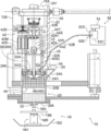
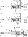
- FIG. 1 is a schematic front view showing a mold making apparatus according to an embodiment of the present invention in a state during molding. It is the elements on larger scale which expand and show a part of casting_mold
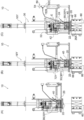
- FIG. 2 is a schematic front view showing the mold making apparatus of FIG. 1 in a state during cleaning and maintenance. It is a schematic front view which shows the one part operating state of the mold making apparatus of FIG. The operating state changes in the order of (A), (B), and (C).
- FIG. 1 is a schematic front view of a mold making apparatus 10 according to the present embodiment (a part of which is a sectional view in front view).
- FIG. 2 is an enlarged view of a part of the mold making apparatus 10 of FIG. A partially enlarged view is shown.
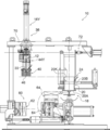
- FIG. 3 shows a left side view of the mold making apparatus 10
- FIG. 4 shows an example of a state immediately after filling the foam mixture of the mold making apparatus 10 in a schematic front view
- FIG. The state at the time of cleaning and maintenance of the mold making apparatus 10 is shown in a schematic front view.
- the mold making apparatus 10 includes a control panel (not shown).
- the control panel includes an operation unit and a storage unit that stores a control processing program for the mold making apparatus 10.
- the mold making apparatus 10 operates by executing a program in accordance with the operation of the operation unit by the operator.
- the mold making apparatus 10 includes a tank 20 and a lid member 30.
- the tank 20 has a bottomed cylindrical shape (a container shape in a broad sense) provided with a bottom wall portion 20A, and is formed with an opening 20K that is open to the side opposite to the bottom wall portion 20A.
- the tank 20 is supplied with materials for producing a foamed mixture (sand (particulate aggregate in a broad sense), water-soluble binder, water, and additives (for example, foaming agent)) and can store them.
- foamed mixture sand (particulate aggregate in a broad sense)
- water-soluble binder for example, foaming agent
- additives for example, foaming agent
- a filling hole 22 is formed through the bottom wall portion 20 ⁇ / b> A of the tank 20.
- One filling hole 22 in the tank 20 is set as an example in the present embodiment (see FIG. 5), and is opened and closed by the stopper mechanism 18.
- a material supply unit 24 for pouring a material into the tank 20 is formed on the side of the opening 20K in the side wall 20B of the tank 20.
- the material supply unit 24 includes a hole 24H formed through the side wall 20B and an inclined chute 24A for guiding the material to the hole 24H.
- a material supply device 28 (illustrated in a block form) is provided above the chute 24A.
- the material supply apparatus 28 is provided with the supply mechanism for every material.
- the cover member 30 is arrange
- a seal member (packing) is provided on the outer peripheral portion of the lid member 30 in contact with the opening 20K side of the tank 20 so that the inside of the tank 20 is airtight.
- the mold making apparatus 10 includes a stirring mechanism 12.
- the stirring mechanism 12 includes a stirring blade 40 at the lower portion thereof, and the foamed mixture is produced by stirring the material inside the tank 20 with the stirring blade 40 in a state where the opening 20K side is closed by the lid member 30. It has become.
- the mold making apparatus 10 includes a mold mechanism 14 on the lower side of the apparatus.
- the mold mechanism 14 includes a mold 60 for forming a mold by molding the foamed mixture kneaded by the stirring mechanism 12 into a predetermined shape.
- a filling hole 66 that is disposed adjacent to the filling hole 22 in the tank 20 is formed through the mold 60.
- the mold making apparatus 10 includes a compressed air supply mechanism 50.
- the compressed air supply mechanism 50 is used when the foam mixture in the tank 20 is filled from the filling hole 22 into the cavity (mold forming space) of the mold 60 through the filling hole 66 with the filling hole 22 opened. Compressed air is supplied into the tank 20.
- the mold making apparatus 10 also includes a mold pushing mechanism (not shown) for taking out the mold from the mold 60 by opening the mold 60 in conjunction with the mold mechanism 14.
- the mold making apparatus 10 includes a first moving mechanism 72 for moving the tank 20 along the airframe upper frame 70 extending in the left-right direction of the apparatus (in the arrow X direction).
- the first moving mechanism 72 includes a first position (position shown in FIG. 1) where the tank 20 is placed at the time of molding, and a second position (see FIG. 6) retracted from the first position to the right side of the apparatus. And a mechanism for moving between the position shown).
- a first moving mechanism 72 for moving the tank 20 shown in FIG. 1 in the left-right direction of the apparatus includes a guide portion (not shown) extending in the left-right direction of the apparatus along the fuselage upper frame 70 and travels along the guide section.
- a possible traveling carriage 72B is provided.
- the traveling range of the traveling carriage 72 ⁇ / b> B is a range including the upper side of the mold 60.
- the tank 20 is attached to the traveling carriage 72B via a vertically moving cylinder 72Y. In other words, the tank 20 is suspended and supported by the cylinder 72Y with respect to the traveling carriage 72B. As shown in FIG. 4, the tank 20 is movable up and down to a position where it is pressed against the mold 60 by the operation of the cylinder 72Y.
- a rod 72D1 extending in the left-right direction of the device is fixed to the upper end of the traveling carriage 72B.
- the rod 72D1 constitutes a part of a cylinder 72D fixed to the right side of the device upper frame 70, and can be expanded and contracted in the left-right direction of the device by the operation of the cylinder 72D. That is, the first moving mechanism 72 is configured to move the tank 20 in the left-right direction of the apparatus as the traveling carriage 72B travels (moves) along the guide portion (not shown).
- the dashed-dotted line 72A in the figure has shown the axial center of rod 72D1.
- the stirring mechanism 12 includes a stirring blade operating mechanism 42 for operating the stirring blade 40.
- the stirring blade operating mechanism 42 includes a rotation shaft 42A for rotating the stirring blade 40.
- the rotating shaft 42A extends along the vertical direction of the apparatus (the same direction as the depth direction of the tank 20), penetrates the central portion of the lid member 30, and the stirring blade 40 is fixed to the lower end portion. It is arranged to be rotatable around the axis.
- the rotating shaft 42A has a configuration in which the upper end portion side is connected to the output shaft of the motor 42M via the driving force transmitting portion 42B. That is, in the agitating mechanism 12, the contents of the tank 20 are agitated (kneaded) by rotating the agitating blade 40 suspended and supported by the rotating shaft 42A when the motor 42M is operated.
- the rotating shaft 42A is supported by a horizontally disposed intermediate plate 32B, and includes a rotating shaft outer tube 42A1 and a rotating shaft inner tube 42A2, so that the structure can be expanded and contracted.
- the rotation shaft outer cylinder 42A1 and the rotation shaft inner cylinder 42A2 extend in the vertical direction of the apparatus, and the rotation shaft inner cylinder 42A2 extends from the rotation shaft outer cylinder 42A1 to the lower side of the rotation shaft outer cylinder 42A1.
- the above-described stirring blade 40 is fixed to the lower end portion of the rotary shaft inner cylinder 42A2.
- a bowl-shaped guide disk 42 ⁇ / b> D is fixed in advance to an intermediate portion in the longitudinal direction of the rotation shaft inner cylinder 42 ⁇ / b> A ⁇ b> 2.
- the guide disk 42D is provided coaxially with the rotation shaft inner cylinder 42A2 and is disposed so as to protrude outward in the radial direction of the rotation shaft inner cylinder 42A2.
- On the upper surface side of the radially outer portion of the guide disk 42D there is provided a first roller 43A that is driven to rotate when the guide disk 42D rotates integrally with the rotary shaft inner cylinder 42A2.
- a second roller 43B is provided on the lower surface side of the radially outer portion of the guide disk 42D. The second roller 43B is driven to rotate when the guide disk 42D rotates integrally with the rotary shaft inner cylinder 42A2.
- the second roller 43B is disposed below the first roller 43A with the guide disk 42D interposed therebetween.
- the first roller 43A and the second roller 43B are rotatably attached to the rod end 44Z, and the directions of the rotation axes of the first roller 43A and the second roller 43B are set along the radial direction of the guide disk 42D.
- the rod end 44Z is formed in an inverted L shape, and includes an upper wall portion 44Z1 disposed on the upper side of the guide disk 42D and a side wall portion 44Z2 disposed on the side of the guide disk 42D.
- the first roller 43A and the second roller 43B described above are rotatably attached to the side wall portion 44Z2 of the rod end 44Z, and a rod extending in the vertical direction of the device is disposed on the upper surface side of the upper wall portion 44Z1 of the rod end 44Z.
- the lower end of the main body 44A is fixed.
- the rod body 44A and the rod end 44Z constitute a part of the servo cylinder 44Y.
- the upper part of the rod main body 44A is disposed in the cylinder 44S of the servo cylinder 44Y and is connected to a ball screw (not shown).
- the rod body 44A is configured to move relative to the cylinder 44S extending in the apparatus vertical direction in the apparatus vertical direction.
- the servo cylinder 44Y includes an electric servo motor 44M (illustrated as a block) for rotationally driving the ball screw.
- the stirring blade 40 is movable in the vertical direction of the apparatus by operating the servo cylinder 44Y by driving the electric servo motor 44M.
- a set of servo cylinder 44Y, first roller 43A, and second roller 43B is provided for the guide disk 42D.
- a rotating shaft is provided for the guide disk 42D.
- the servo cylinder 44Y is set at a position deviated from the cross section shown in FIGS. 1 to 4 as an example, but for the sake of convenience, the cross section shown in FIGS. This is illustrated by a two-dot chain line (imaginary line).
- first roller 43A and the second roller 43B are omitted except for FIG.
- the rotation axes of the first roller 43A and the second roller 43B are indicated by alternate long and short dash lines.
- the stirring blade 40 includes a frame body 40 ⁇ / b> A formed in a frame shape, and also includes a lattice-like net portion 40 ⁇ / b> B provided inside the frame body 40 ⁇ / b> A.
- stirring blades 40 of the present embodiment stirring blades of other shapes that do not include the frame body 40A and the net portion 40B may be applied.
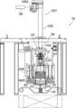
- the tank 20 is simplified and shown in a bottomed cylindrical shape, and the lower portion of the stirring mechanism 12 is simplified in a state where the tank 20 is seen through.
- a hole opening blocking portion 46 capable of closing the opening of the filling hole 22 (illustrated by an imaginary line (two-dot chain line) in FIG. 5) is provided.
- the hole opening blocking portion 46 is a part of a substantially rectangular plate-shaped portion (a backflow prevention shielding plate) including a protruding portion that protrudes from the lower end portion of the stirring blade 40 to the outside in the thickness direction of the stirring blade 40.
- the stirring blade 40 including the hole opening blocking portion 46 that is, the hole opening blocking portion 46, has an opening position 46 ⁇ / b> X (see FIG. 2) where the opening of the filling hole 22 is opened, and A second moving mechanism 45 is provided that moves between a closing position 46Y (see FIG. 4) for closing.
- the second moving mechanism 45 includes a hole opening blocking portion among the servo cylinder 44Y, the first roller 43A, the second roller 43B, the guide disk 42D, the rotating shaft inner tube 42A2, the rotating shaft outer tube 42A1, and the stirring blade 40 described above. It is configured to include a portion excluding 46.
- the electric servo motor 44M of the servo cylinder 44Y that constitutes a part of the second moving mechanism 45 is connected to the open / close control unit 48, and the drive is controlled by the open / close control unit 48.
- the open / close control unit 48 supplies the compressed air to the inside of the tank 20 by the compressed air supply mechanism 50 (see FIG. 2), so that the foamed mixture inside the tank 20 shown in FIG. Before filling the cavity of the mold 60 through the filling hole 66, the hole opening closing portion 46 shown in FIG. 5 is moved to the side (upward side) away from the closing position 46Y (see FIG. 4).
- the second moving mechanism 45 more specifically, driving of the electric servo motor 44M of the servo cylinder 44Y is controlled.
- the open / close control unit 48 supplies the compressed air from the filling hole 22 by the compressed air supply mechanism 50 (see FIG. 2) supplying compressed air to the inside of the tank 20 and the inside of the tank 20 shown in FIG.
- the second moving mechanism 45 shown in FIG. 5 is controlled so that the hole opening closing portion 46 shown in FIG. 4 is moved to the closing position 46Y after the cavity of the mold 60 is filled through the filling hole 66. .
- the mold 60 forms a cavity with a fixed mold 62 that is one mold and a movable mold 64 that is the other mold.
- the movable mold 64 is movable in the left-right direction of the apparatus by a movable mechanism 14A.
- the movable mechanism 14A is provided on the machine base 14B, and is configured to include a cylinder 14A1 arranged with the left-right direction of the apparatus as an axial direction.
- the movable mold 64 can change the orientation of the movable mold split surface in a state of being disposed at a position away from the fixed mold 62. .
- the fixed die 62 is supported by a support mechanism portion 14C provided on the machine base 14B, and is disposed on the side of the movable die 64 (on the left side of the apparatus in this embodiment). .
- the filling hole 66 described above is formed through the upper wall portion disposed on the upper side of the mold 60.
- the filled hole 66 in the present embodiment is composed of a cutout portion of the upper wall portion 62A of the fixed mold 62 and a cutout portion of the upper wall portion 64A of the movable mold 64.
- the servo cylinder 16Y is supported on the fuselage upper frame 70.
- the servo cylinder 16Y includes a cylinder 16S and a rod 16A arranged with the apparatus vertical direction as an axial direction, and an electric servo motor 16M for driving (see FIG. 3).
- the lower end portion of the rod 16 ⁇ / b> A is connected to the lid member 30 via the connection structure portion 32.
- the connecting structure portion 32 includes a plurality of rods 32 ⁇ / b> A that are fixed and erected on the upper surface side of the lid member 30, and an intermediate plate 32 ⁇ / b> B to which an upper end portion of the rod 32 ⁇ / b> A is fixed.
- the intermediate plate 32B supports the rotary shaft 42A described above.
- the lid member 30 is slidably disposed in a sealed state (sealed state) with the inner surface of the tank 20, and the electric servo motor 16M (see FIG. 3) of the servo cylinder 16Y is operated to operate the tank 20. It moves in the direction approaching the bottom wall 20A and in the opposite direction (in other words, the vertical direction of the apparatus).
- the raising / lowering mechanism 36 comprised including the servo cylinder 16Y and the connection structure part 32 WHEREIN: The 1st position 30X which positions the cover member 30 in the opening part 20K side rather than the flow path lower end of the material supply part 24, The material supply unit 24 is moved up and down between a second position 30Y (see FIG. 8C) located on the bottom wall 20A side with respect to the lower end of the flow path.
- the electric servomotor 16M of the lifting mechanism 36 is connected to the lifting control unit 38.
- the elevating control unit 38 is configured such that the lid member 30 is arranged at the first position 30X (the position shown in FIG. 2) when the material is supplied from the material supply unit 24 shown in FIG.
- the lid member 30 is moved.
- the lifting mechanism 36 is controlled so as to be arranged at the second position 30Y (position shown in FIG. 8C).
- a stopper mechanism 18 as a filling hole opening / closing mechanism is provided below the tank 20 and above the mold mechanism 14 (see FIG. 1).
- the stopper mechanism 18 includes a stopper 18 ⁇ / b> A for closing the filling hole 22 of the bottom wall 20 ⁇ / b> A of the tank 20.
- the stopper plug 18A protrudes upward from a horizontally disposed stopper plug plate 18B.
- the stopper plate 18B is attached to the upper end of the piston rod 18R of the upward cylinder 18Y, and moves up and down by the operation of the cylinder 18Y.
- the stopper mechanism 18 can close the filling hole 22 of the tank 20 with the stopper plug 18A.
- the support member 18D that supports the cylinder 18Y is movable in the left-right direction of the apparatus by a moving mechanism (not shown).
- the compressed air supply mechanism 50 includes a port 52A and a pressure gauge 52G in the lid member 30, and a compressed air supply device 52C is connected to the port 52A via a hose 52B, a flow meter 52D, and a three-way valve 52E.
- the compressed air supply device 52C can supply compressed air to the internal space of the tank 20 through the flow meter 52D, the three-way valve 52E, the hose 52B, and the port 52A.
- the pressure gauge 52G can measure the pressure in the internal space of the tank 20.
- the compressed air supply mechanism 50 includes an air supply control unit 54 connected to the pressure gauge 52G, the flow meter 52D, the three-way valve 52E, and the compressed air supply device 52C. In the figure, the connection between the pressure gauge 52G and the air supply controller 54 is not shown.
- the air supply control unit 54 controls each operation of the compressed air supply device 52C and the three-way valve 52E.
- the material supply device 28 (FIG. 2), the material (sand, water-soluble binder, water, and additive) for producing the foamed mixture is supplied (introduced) from the material supply unit 24 into the tank 20 (see arrow A).
- the stirring blade 40 is moved upward in a direction away from the bottom wall portion 20A of the tank 20 by the operation of the servo cylinder 44Y. Further, the lid member 30 is lowered by the operation of the servo cylinder 16Y (elevating mechanism 36) (see arrow C). At this time, in order to set the pressure in the tank 20 to atmospheric pressure, the three-way valve 52E provided in the compressed air supply mechanism 50 (see FIG. 2, a valve for releasing to the atmosphere) is switched and exhausted. The lid member 30 is disposed at the second position 30Y located on the bottom wall portion 20A side from the lower end of the flow path of the material supply portion 24.
- the tank 20 is lowered by the operation of the cylinder 72Y, and the tank 20 is strongly pressed against the mold 60. Thereby, the filling hole 22 of the tank 20 is disposed adjacent to the filling hole 66 of the mold 60. At this time, the lid member 30 and the stirring blade 40 in the tank 20 are also lowered synchronously by the operation of the servo cylinder 16Y.
- the stirring blade operating mechanism 42 of the stirring mechanism 12 is operated so that the stirring blade 40 stirs the foamed mixture (thixotropic property) inside the tank 20.
- compressed air is supplied to the inside of the tank 20 by the compressed air supply mechanism 50 (see arrow E), and the foamed mixture inside the tank 20 is molded from the filling hole 22 through the filling hole 66 to the mold. 60 cavities are filled.
- the compressed air supplied from the compressed air supply mechanism 50 to the inside of the tank 20 leaks from the material supply unit 24. Can be suppressed. Further, since the compressed air is supplied into the tank 20 by the compressed air supply mechanism 50 while the stirring blade 40 agitates the foamed mixture inside the tank 20, for example, in the tank 20 without stirring the foamed mixture. Compared with the case where compressed air is supplied, the amount of compressed air can be suppressed (and the energy for supplying compressed air can be reduced).
- the stirring blade 40 is rotated to reduce the viscosity of the foamed mixture (non-Newtonian fluid) and improve the fluidity. Therefore, the amount of compressed air when supplying the foamed mixture can be suppressed, and the supply of the foamed mixture is improved. Furthermore, since the compressed air smoothes the irregularities on the surface of the foamed mixture, stable supply performance can be ensured.
- the steps shown in FIGS. 7C to 8C correspond to the second step of this embodiment.
- the operation speed at the time of stirring of the stirring blade 40 in the step (second step) shown in FIG. 8C is the same as that at the time of stirring of the stirring blade 40 in the step (first step) shown in FIG. It is set to be slower than the operating speed. Accordingly, in the present embodiment, the foam mixture is stabilized from the filling hole 22 through the filling hole 66 while the properties of the foam mixture inside the tank 20 shown in FIG. Can be stably filled.
- step (second step) shown in FIG. 8C when the foam mixture in the tank 20 is filled from the filling hole 22 into the cavity of the mold 60 through the filling hole 66, the foam mixture
- the pressure of the compressed air supplied to the inside of the tank 20 between the start of filling and immediately before the completion of filling is higher than the pressure of compressed air supplied to the inside of the tank 20 at the completion of filling of the foamed mixture and immediately after the filling. Is set to be low. For this reason, it is possible to prevent or suppress the compressed air from passing through the foaming mixture during filling of the foaming mixture, and to prevent the thermally expanded foaming mixture from flowing backward from the cavity of the mold 60 after the filling of the foaming mixture is completed. Can do.
- the stirring blade 40 is moved in a direction away from the bottom wall portion 20A before the foamed mixture inside the tank 20 is filled into the cavity of the mold 60 (FIG. 8B). And (C)), when the foam mixture is filled into the cavity of the mold 60, it is possible to prevent or suppress the foam mixture from being difficult to pass through the filling hole 22 by the stirring blade 40 including the hole opening blocking portion 46. it can.
- the servo cylinder 44Y is By operating, as shown in FIG. 4, the hole opening blocking portion 46 that is a part of the stirring blade 40 is moved to the blocking position 46Y, and the hole opening blocking portion 46 blocks the opening of the filling hole 22 for a predetermined time. Also by this, the backflow of the foaming mixture from the cavity of the mold 60 to the tank 20 can be prevented.
- the tank 20 is raised by the operation of the cylinder 72Y, and the tank 20 is separated from the mold 60.
- the lid member 30 and the stirring blade 40 in the tank 20 are also raised by the operation of the servo cylinder 16Y, and the lid member 30 is located on the opening 20K side from the lower end of the flow path of the material supply unit 24. It arrange
- the stopper mechanism 18 moves from the right side of the apparatus directly below the tank 20 by the operation of a moving mechanism (not shown). Moreover, when the cylinder 18Y of the stopper mechanism 18 is operated and the stopper plug 18A is raised (see arrow F), the filling hole 22 of the bottom wall portion 20A of the tank 20 is formed as shown in FIG. Blocked. That is, the mold making apparatus 10 returns to the operation state of FIG. 7A after the operation state of FIG. 9C, and the cycle described above is repeated hereinafter. In addition, if it supplements about the mold making apparatus 10 which returned to the operation state of FIG. 7 (A), since the cover member 30 is arrange
- the foaming mixture does not scatter outside the tank 20. That is, in order to fill the mold 60 with the foamed mixture, compressed air is supplied to the inside of the tank 20 by the compressed air supply mechanism 50, and the foamed mixture inside the tank 20 is passed from the filling hole 22 through the filling hole 66. The cavity of the mold 60 is filled. And the efficiency with which the cavity of the metal mold
- the foaming mixture is supplied from the tank 20 to the cavity of the mold 60 in the vertical direction from the upper side of the apparatus to the lower side of the apparatus.
- the supply direction may be set to a horizontal direction or a diagonally downward direction.
- a material supply port is provided in a cover member (30). It is good also as a structure which provides the opening-and-closing part which opens and closes the said material supply port and supplies the material from the said material supply port to the inside of a tank (20).
- the stirring blade (40) is rotated in order to improve the filling property of the foam mixture into the mold and ensure the ability to stably supply the foam mixture.
- a function of vibrating the stirring blade (40) or vibrating the tank (20) may be provided.
- occlusion part 46 and opening-and-closing control part 48 which are shown by FIG. 5 are provided, Such a structure is preferable from a viewpoint of the backflow prevention mentioned above, but the hole opening obstruction
- the one filling hole 22 is penetratingly formed in 20 A of bottom wall parts of the tank 20, as a modification of the said embodiment, several bottom wall part (20A) of a tank (20) is used. It is also possible to adopt a configuration in which the filling holes are formed to penetrate and a plurality of closing stoppers are set in the stopper mechanism (filling hole opening / closing mechanism) corresponding to these filling holes.
- the plurality of filling holes may include a filling hole set at the same position as the filling hole 22 shown in FIG. 5 and may be set so as to line up in a row in the apparatus plan view.
- the stirring blade (40) is set to stop in a state of extending in the same direction as the direction in which the plurality of filling holes are arranged in plan view of the apparatus (in other words, the stirring blade (40 ) May be set so that the stirring blade (40) and the plurality of filling holes overlap in plan view of the apparatus.
- the position of the lid member 30 when the material inside the tank 20 shown in FIG. 7B is agitated by the agitating blade 40 is shown in FIG. 7B.
- the second position 30Y (see FIG. 7C) may be used instead of the first position 30X.
- the timing of displacing the position of the lid member 30 from the first position 30X to the second position 30Y is from the material supply unit 24 shown in FIG. Any material may be used after the material is supplied and before the foam mixture in the tank 20 shown in FIG. 8C is filled from the filling hole 22 into the cavity of the mold 60 through the filling hole 66. It is also possible to set the timing.
- the timing which displaces the position of the cover member 30 from the 2nd position 30Y to the 1st position 30X sets the foaming mixture inside the tank 20 shown by FIG. After filling the cavity of the mold 60 from the filling hole 66 through the filling hole 66 and before the material is supplied from the material supply unit 24 shown in FIG. It is also possible to set the timing.
- the stirring blade 40 is operated from the bottom wall part 20A of the tank 20 by the action
- the compressed air supply mechanism 50 supplies the foamed mixture inside the tank 20 shown in FIG. 8C into the cavity of the mold 60 from the filling hole 22 through the filling hole 66.
- the setting of the pressure of the compressed air to be performed is preferably the setting as in the above embodiment, but a setting other than the setting in the above embodiment may be adopted.
- the compressed air supplied from the compressed air supply mechanism (50) to the inside of the tank (20) is not limited to the atmosphere, but is an inert gas such as nitrogen gas or argon gas or carbon dioxide gas supplied from a gas cylinder. Also good.
Abstract
Description
まず、鋳型造型装置10の全体構成について概説する。なお、鋳型造型装置10は、図示しない制御盤を備えており、この制御盤は、操作部を備えると共に、鋳型造型装置10の制御処理のプログラムを記憶した記憶部を含んで構成されている。そして、鋳型造型装置10は、操作者による操作部の操作に応じてプログラムを実行して作動するようになっている。 (Overall configuration of mold making equipment)
First, the overall configuration of the
次に、各機構について説明する。 (About each mechanism)
Next, each mechanism will be described.
次に、鋳型造型装置10を用いて発泡混合物を金型60(図1参照)のキャビティに充填して鋳型を造型する鋳型造型方法について図7~図9を用いて説明しながら、上記実施形態の作用及び効果について説明する。なお、以下に説明する鋳型造型方法における制御処理は、鋳型造型装置10の操作者による操作部(図示省略)の操作に応じて鋳型造型装置10の記憶部(図示省略)に記憶された制御処理のプログラムが実行されることで、以下に説明する順に実行される。 (Action / Effect)
Next, a mold making method for filling the foam mixture into the cavity of the mold 60 (see FIG. 1) using the
なお、上記実施形態では、槽20から金型60のキャビティへの発泡混合物の供給方向が装置上方側から装置下方側へ向かう縦方向とされているが、槽から金型のキャビティへの発泡混合物の供給方向は、横方向や斜め下方向に設定されてもよい。 (Supplementary explanation of the embodiment)
In the above embodiment, the foaming mixture is supplied from the
本明細書に記載された全ての文献、特許出願、及び技術規格は、個々の文献、特許出願、及び技術規格が参照により取り込まれることが具体的にかつ個々に記載された場合と同様に、本明細書中に参照により取り込まれる。 The entire disclosure of Japanese application 2017-1000026 is incorporated herein by reference.
All documents, patent applications, and technical standards mentioned herein are specifically and individually described as individual documents, patent applications, and technical standards are incorporated by reference, Incorporated herein by reference.
Claims (8)
- 発泡混合物製造用の材料が供給され、底壁部に充填孔が貫通形成されると共に、前記底壁部の側とは反対側へ開放された開口部が形成された槽と、
前記槽における前記開口部の側を閉塞する蓋部材と、
前記槽における前記充填孔を開閉する充填孔開閉機構と、
前記蓋部材で前記開口部の側を閉塞した状態で前記槽の内部の材料を攪拌羽根で攪拌して発泡混合物を製造する攪拌機構と、
前記槽における前記充填孔に隣接配置される被充填孔が貫通形成された金型と、
前記充填孔を開放した状態で前記槽の内部の前記発泡混合物を前記充填孔から前記被充填孔を介して前記金型のキャビティに充填させる場合に圧縮空気を前記槽の内部に供給する圧縮空気供給機構と、
を有する鋳型造型装置。 A tank in which a material for producing a foam mixture is supplied, a filling hole is formed through the bottom wall portion, and an opening that is open to the opposite side of the bottom wall portion is formed;
A lid member for closing the side of the opening in the tank;
A filling hole opening and closing mechanism for opening and closing the filling hole in the tank;
A stirring mechanism for producing a foamed mixture by stirring the material inside the tank with a stirring blade in a state where the side of the opening is closed with the lid member;
A mold in which a filling hole arranged adjacent to the filling hole in the tank is formed;
Compressed air for supplying compressed air to the inside of the tank when the foam mixture in the tank is filled into the cavity of the mold from the filling hole through the filled hole with the filling hole opened. A supply mechanism;
A mold making apparatus. - 前記攪拌羽根に設けられて前記充填孔の開口を閉塞可能な孔開口閉塞部と、
前記孔開口閉塞部を、前記充填孔の開口を開放する開放位置と、前記充填孔の開口を閉塞する閉塞位置と、の間で移動させる移動機構と、
前記圧縮空気供給機構が圧縮空気を前記槽の内部に供給して前記槽の内部の前記発泡混合物を前記充填孔から前記被充填孔を介して前記金型のキャビティに充填させた後に、前記孔開口閉塞部を前記閉塞位置に移動させるように前記移動機構を制御する開閉制御部と、
を有する、請求項1記載の鋳型造型装置。 A hole opening blocking portion provided on the stirring blade and capable of blocking the opening of the filling hole;
A moving mechanism for moving the hole opening blocking portion between an opening position for opening the opening of the filling hole and a closing position for closing the opening of the filling hole;
The compressed air supply mechanism supplies compressed air to the inside of the tank to fill the foam mixture in the tank into the cavity of the mold from the filling hole through the filling hole, and then the hole. An opening / closing control unit for controlling the moving mechanism so as to move the opening closing part to the closing position;
The mold making apparatus according to claim 1, comprising: - 前記槽の側壁部における前記開口部の側には、前記槽の内部に材料を流し込むための材料供給部が形成されており、
前記蓋部材を、前記材料供給部の流路下端よりも前記開口部の側に位置する第一位置と、前記材料供給部の流路下端よりも前記底壁部の側に位置する第二位置と、の間で昇降させる昇降機構と、
前記材料供給部から前記槽の内部に材料が供給される時点で前記蓋部材が前記第一位置に配置されているように前記昇降機構を制御すると共に、前記槽の内部の前記発泡混合物を前記充填孔から前記被充填孔を介して前記金型のキャビティに充填させる時点で前記蓋部材が前記第二位置に配置されているように前記昇降機構を制御する昇降制御部と、
を有する請求項1又は請求項2に記載の鋳型造型装置。 On the side of the opening in the side wall of the tank, a material supply part for pouring material into the tank is formed,
A first position where the lid member is positioned closer to the opening than the lower end of the flow path of the material supply unit, and a second position which is positioned closer to the bottom wall than the lower end of the flow path of the material supply unit Elevating mechanism for elevating between, and
The elevating mechanism is controlled so that the lid member is disposed at the first position when the material is supplied from the material supply unit to the inside of the tank, and the foamed mixture inside the tank is An elevating control unit that controls the elevating mechanism so that the lid member is disposed at the second position at the time of filling the cavity of the mold from the filling hole through the filled hole;
The mold making apparatus according to claim 1 or 2, comprising: - 発泡混合物を金型のキャビティに充填して鋳型を造型する鋳型造型方法であって、
底壁部に充填孔が貫通形成されると共に前記底壁部の側とは反対側へ開放された開口部が形成された槽に、発泡混合物製造用の材料を供給し、前記槽における前記開口部の側を蓋部材で閉塞しかつ前記充填孔を充填孔開閉機構で閉塞した状態で、前記槽の内部の材料を攪拌羽根で攪拌して発泡混合物を製造する第一工程と、
前記第一工程の後に、前記充填孔開閉機構を作動させて前記充填孔を開放し、前記金型に貫通形成された被充填孔に前記充填孔を隣接配置させるように前記槽を前記金型に押し付け、前記攪拌羽根で前記槽の内部の前記発泡混合物を攪拌しながら、前記槽の内部に圧縮空気を供給して前記槽の内部の前記発泡混合物を前記充填孔から前記被充填孔を介して前記金型のキャビティに充填させる第二工程と、
を有する鋳型造型方法。 A mold making method of filling a foam mixture into a mold cavity to mold a mold,
A material for producing a foaming mixture is supplied to a tank in which a filling hole is formed through the bottom wall part and an opening part opened to the side opposite to the side of the bottom wall part is formed, and the opening in the tank is supplied. A first step of producing a foam mixture by stirring the material inside the tank with a stirring blade in a state where the side of the part is closed with a lid member and the filling hole is closed with a filling hole opening and closing mechanism;
After the first step, the filling hole opening / closing mechanism is operated to open the filling hole, and the tank is placed in the mold so that the filling hole is disposed adjacent to the filling hole formed through the mold. While stirring the foamed mixture inside the tank with the stirring blade, compressed air is supplied to the inside of the tank, and the foamed mixture inside the tank is passed from the filling hole to the filling hole. A second step of filling the cavity of the mold,
A mold making method. - 前記第二工程における前記攪拌羽根の攪拌時の動作速度は、前記第一工程における前記攪拌羽根の攪拌時の動作速度よりも、低速に設定されている、請求項4記載の鋳型造型方法。 The mold making method according to claim 4, wherein an operation speed at the time of stirring of the stirring blade in the second step is set lower than an operation speed at the time of stirring of the stirring blade in the first step.
- 前記第一工程において前記槽の内部の材料を前記攪拌羽根で攪拌して発泡混合物を製造した後、前記第二工程において前記槽の内部の前記発泡混合物を前記充填孔から前記被充填孔を介して前記金型のキャビティに充填させる前に、前記攪拌羽根を前記底壁部から離間させる方向に移動させる、請求項4又は請求項5に記載の鋳型造型方法。 In the first step, the material inside the tank is stirred with the stirring blade to produce a foamed mixture, and then in the second step, the foamed mixture inside the tank is passed from the filling hole through the filled hole. 6. The mold making method according to claim 4, wherein the stirring blade is moved in a direction away from the bottom wall portion before filling the cavity of the mold.
- 前記第二工程において前記槽の内部の前記発泡混合物を前記充填孔から前記被充填孔を介して前記金型のキャビティに充填させる場合に、前記発泡混合物の充填開始時から充填完了直前までの間に前記槽の内部に供給される圧縮空気の圧力は、前記発泡混合物の充填完了時及び充填完了直後に前記槽の内部に供給される圧縮空気の圧力よりも、低く設定されている、請求項4~請求項6のいずれか1項に記載の鋳型造型方法。 In the second step, when filling the foam mixture in the tank from the filling hole into the cavity of the mold through the filling hole, from the start of filling of the foam mixture to just before completion of filling. The pressure of the compressed air supplied to the inside of the tank is set to be lower than the pressure of the compressed air supplied to the inside of the tank at the completion of filling the foamed mixture and immediately after the filling. The mold making method according to any one of claims 4 to 6.
- 前記第二工程において前記槽の内部の前記発泡混合物を前記充填孔から前記被充填孔を介して前記金型のキャビティに充填させた後、前記充填孔の開口を前記攪拌羽根の一部が閉塞する位置に前記攪拌羽根を移動させる、請求項4~請求項7のいずれか1項に記載の鋳型造型方法。 In the second step, the foam mixture in the tank is filled from the filling hole into the cavity of the mold through the filling hole, and then the opening of the filling hole is partially blocked by the stirring blade. The mold making method according to any one of claims 4 to 7, wherein the stirring blade is moved to a position to be moved.
Priority Applications (7)
| Application Number | Priority Date | Filing Date | Title |
|---|---|---|---|
| US16/607,455 US11554411B2 (en) | 2017-05-19 | 2018-03-05 | Casting mold making apparatus and mold making method |
| MX2019008090A MX2019008090A (en) | 2017-05-19 | 2018-03-05 | Casting mold shaping device and casting mold shaping method. |
| BR112019015320-9A BR112019015320A2 (en) | 2017-05-19 | 2018-03-05 | CASTING MOLD MANUFACTURING APPLIANCE AND MOLD MANUFACTURING METHOD |
| KR1020197017321A KR102446124B1 (en) | 2017-05-19 | 2018-03-05 | Mold molding apparatus and mold molding method |
| CN201880004514.0A CN109982788A (en) | 2017-05-19 | 2018-03-05 | Casting mold device and casting mold method |
| EP18802615.7A EP3626363B1 (en) | 2017-05-19 | 2018-03-05 | Casting mold shaping device and casting mold shaping method |
| RU2019138184A RU2019138184A (en) | 2017-05-19 | 2018-03-05 | A device for making a cast mold and a method for making a cast mold |
Applications Claiming Priority (2)
| Application Number | Priority Date | Filing Date | Title |
|---|---|---|---|
| JP2017-100267 | 2017-05-19 | ||
| JP2017100267A JP6822315B2 (en) | 2017-05-19 | 2017-05-19 | Molding equipment and molding method |
Publications (1)
| Publication Number | Publication Date |
|---|---|
| WO2018211785A1 true WO2018211785A1 (en) | 2018-11-22 |
Family
ID=64273689
Family Applications (1)
| Application Number | Title | Priority Date | Filing Date |
|---|---|---|---|
| PCT/JP2018/008431 WO2018211785A1 (en) | 2017-05-19 | 2018-03-05 | Casting mold shaping device and casting mold shaping method |
Country Status (10)
| Country | Link |
|---|---|
| US (1) | US11554411B2 (en) |
| EP (1) | EP3626363B1 (en) |
| JP (1) | JP6822315B2 (en) |
| KR (1) | KR102446124B1 (en) |
| CN (1) | CN109982788A (en) |
| BR (1) | BR112019015320A2 (en) |
| MX (1) | MX2019008090A (en) |
| RU (1) | RU2019138184A (en) |
| TW (1) | TW201900297A (en) |
| WO (1) | WO2018211785A1 (en) |
Cited By (2)
| Publication number | Priority date | Publication date | Assignee | Title |
|---|---|---|---|---|
| US11504886B2 (en) * | 2020-03-19 | 2022-11-22 | Sintokogio, Ltd. | Molding machine |
| US11794380B2 (en) * | 2020-03-19 | 2023-10-24 | Sintokogio, Ltd. | Molding machine |
Families Citing this family (3)
| Publication number | Priority date | Publication date | Assignee | Title |
|---|---|---|---|---|
| JP7230871B2 (en) | 2020-03-19 | 2023-03-01 | 新東工業株式会社 | mold making method |
| CN112157247A (en) * | 2020-09-29 | 2021-01-01 | 陈秀兰 | Sand casting system |
| CN116474608B (en) * | 2023-05-09 | 2023-12-08 | 江苏中金玛泰医药包装有限公司 | Adhesive raw material proportioning equipment and application method thereof |
Citations (5)
| Publication number | Priority date | Publication date | Assignee | Title |
|---|---|---|---|---|
| JPS5594756A (en) * | 1979-01-12 | 1980-07-18 | Naniwa Seisakusho:Kk | Mold sand constant amount blowing mold making machine |
| WO2005089984A1 (en) * | 2004-03-23 | 2005-09-29 | Sintokogio, Ltd. | Casting mold forming apparatus and metal mold unit for use therein |
| WO2006134841A1 (en) * | 2005-06-15 | 2006-12-21 | Sintokogio, Ltd. | Method of controlling foaming mixture |
| WO2007066509A1 (en) * | 2005-12-09 | 2007-06-14 | Sintokogio, Ltd. | Method for controlling foamed aggregate mixture |
| JP2017100267A (en) | 2015-12-04 | 2017-06-08 | 三菱ケミカルインフラテック株式会社 | Holding member of pastic pipe end part and cutting method |
Family Cites Families (16)
| Publication number | Priority date | Publication date | Assignee | Title |
|---|---|---|---|---|
| JPS601099B2 (en) * | 1978-06-22 | 1985-01-11 | 新東工業株式会社 | mold making machine |
| DE3010694A1 (en) * | 1979-03-26 | 1980-10-02 | Acme Cleveland Corp | MOLDING MACHINE |
| US4460032A (en) * | 1982-01-25 | 1984-07-17 | Pettibone Corporation | Method and apparatus for blowing cores etc. using a plunger-cleaned blow box suitable for quick-set sand |
| US4570694A (en) * | 1982-01-25 | 1986-02-18 | Lund Robert S | Mold-blowing apparatus |
| CN2285300Y (en) * | 1996-07-03 | 1998-07-01 | 西安工业学院 | Device for preparing liquid stirred ceramic reinforced metal base composite material |
| JP4425385B2 (en) | 1999-10-06 | 2010-03-03 | プレス工業株式会社 | Construction machinery cab with sliding door |
| CN100500327C (en) * | 2004-03-23 | 2009-06-17 | 新东工业株式会社 | Casting mold forming apparatus and metal mold unit for use therein |
| JP4572847B2 (en) * | 2006-03-08 | 2010-11-04 | マツダ株式会社 | Mold making equipment |
| EP2676724A4 (en) * | 2011-02-17 | 2018-01-24 | Sintokogio, Ltd. | Tank apparatus, circulating-type dispersion system, and dispersion method |
| JP5840082B2 (en) * | 2012-06-25 | 2016-01-06 | 新東工業株式会社 | Foam kneaded material molding apparatus and foam kneaded material molding method |
| JP5958966B2 (en) * | 2013-03-25 | 2016-08-02 | トヨタ自動車株式会社 | Molding apparatus and molding method |
| CN103340750B (en) * | 2013-07-06 | 2015-01-07 | 林凡霞 | Intelligent Chinese medicine concentration earthen pot |
| WO2015037377A1 (en) * | 2013-12-27 | 2015-03-19 | 新東工業株式会社 | Dispersing device, dispersion treatment system, and dispersing method |
| CN104028151A (en) * | 2014-06-20 | 2014-09-10 | 王玙璠 | Internal mixer capable of avoiding material residue |
| CN204865801U (en) * | 2015-06-17 | 2015-12-16 | 宁波大学 | Detachable chemical reaction cauldron |
| JP6378157B2 (en) * | 2015-11-06 | 2018-08-22 | トヨタ自動車株式会社 | Foam sand manufacturing method and manufacturing apparatus thereof |
-
2017
- 2017-05-19 JP JP2017100267A patent/JP6822315B2/en active Active
-
2018
- 2018-03-05 RU RU2019138184A patent/RU2019138184A/en not_active Application Discontinuation
- 2018-03-05 KR KR1020197017321A patent/KR102446124B1/en active IP Right Grant
- 2018-03-05 CN CN201880004514.0A patent/CN109982788A/en active Pending
- 2018-03-05 BR BR112019015320-9A patent/BR112019015320A2/en not_active Application Discontinuation
- 2018-03-05 EP EP18802615.7A patent/EP3626363B1/en active Active
- 2018-03-05 US US16/607,455 patent/US11554411B2/en active Active
- 2018-03-05 MX MX2019008090A patent/MX2019008090A/en unknown
- 2018-03-05 WO PCT/JP2018/008431 patent/WO2018211785A1/en active Application Filing
- 2018-05-09 TW TW107115828A patent/TW201900297A/en unknown
Patent Citations (6)
| Publication number | Priority date | Publication date | Assignee | Title |
|---|---|---|---|---|
| JPS5594756A (en) * | 1979-01-12 | 1980-07-18 | Naniwa Seisakusho:Kk | Mold sand constant amount blowing mold making machine |
| WO2005089984A1 (en) * | 2004-03-23 | 2005-09-29 | Sintokogio, Ltd. | Casting mold forming apparatus and metal mold unit for use therein |
| JP4428385B2 (en) | 2004-03-23 | 2010-03-10 | 新東工業株式会社 | Mold making apparatus and mold apparatus used therefor |
| WO2006134841A1 (en) * | 2005-06-15 | 2006-12-21 | Sintokogio, Ltd. | Method of controlling foaming mixture |
| WO2007066509A1 (en) * | 2005-12-09 | 2007-06-14 | Sintokogio, Ltd. | Method for controlling foamed aggregate mixture |
| JP2017100267A (en) | 2015-12-04 | 2017-06-08 | 三菱ケミカルインフラテック株式会社 | Holding member of pastic pipe end part and cutting method |
Non-Patent Citations (1)
| Title |
|---|
| See also references of EP3626363A4 |
Cited By (2)
| Publication number | Priority date | Publication date | Assignee | Title |
|---|---|---|---|---|
| US11504886B2 (en) * | 2020-03-19 | 2022-11-22 | Sintokogio, Ltd. | Molding machine |
| US11794380B2 (en) * | 2020-03-19 | 2023-10-24 | Sintokogio, Ltd. | Molding machine |
Also Published As
| Publication number | Publication date |
|---|---|
| JP2018192512A (en) | 2018-12-06 |
| RU2019138184A (en) | 2021-06-21 |
| US11554411B2 (en) | 2023-01-17 |
| CN109982788A (en) | 2019-07-05 |
| EP3626363B1 (en) | 2022-09-07 |
| EP3626363A1 (en) | 2020-03-25 |
| EP3626363A4 (en) | 2020-09-23 |
| TW201900297A (en) | 2019-01-01 |
| MX2019008090A (en) | 2019-08-29 |
| JP6822315B2 (en) | 2021-01-27 |
| KR102446124B1 (en) | 2022-09-22 |
| US20210276076A1 (en) | 2021-09-09 |
| KR20200008543A (en) | 2020-01-28 |
| BR112019015320A2 (en) | 2020-03-10 |
Similar Documents
| Publication | Publication Date | Title |
|---|---|---|
| WO2018211785A1 (en) | Casting mold shaping device and casting mold shaping method | |
| JP4441916B2 (en) | Method for filling foam cavity into mold cavity and mold making apparatus | |
| US10099278B2 (en) | Mold-making device and mold-making method | |
| CN107848019B (en) | Kneading mechanism, molding device, and method for producing foamed mixture | |
| JP4281799B2 (en) | Molding method and apparatus for upper and lower molds without casting frame | |
| CN105500515B (en) | Concrete block forming device | |
| CN1933927A (en) | Casting mold forming apparatus and metal mold unit for use therein | |
| CN207540850U (en) | Fill out sand tube parallel connection automatic making device | |
| CN105705267A (en) | Mold shaping device | |
| FI127854B (en) | Method and apparatus for casting concrete products | |
| JP2019202323A (en) | Core molding device | |
| JP6733564B2 (en) | Mold making equipment | |
| CN205362630U (en) | Half solid -state pulping machine | |
| JP2019123005A (en) | Molding device for hollow sand cores | |
| JP2019072726A (en) | Core molding device | |
| JP6729204B2 (en) | Powder feeder | |
| CN103480841A (en) | Powder filling device | |
| CN206869082U (en) | A kind of improved hub extrusion casting mould closing device | |
| JP2019217553A (en) | Core molding method | |
| CN114345188A (en) | New material mixing system | |
| CN114292063A (en) | Lightweight foam concrete and preparation method thereof | |
| CN115401764A (en) | Defoaming and leveling equipment and method for glass kiln lip brick production |
Legal Events
| Date | Code | Title | Description |
|---|---|---|---|
| 121 | Ep: the epo has been informed by wipo that ep was designated in this application |
Ref document number: 18802615 Country of ref document: EP Kind code of ref document: A1 |
|
| ENP | Entry into the national phase |
Ref document number: 20197017321 Country of ref document: KR Kind code of ref document: A |
|
| REG | Reference to national code |
Ref country code: BR Ref legal event code: B01A Ref document number: 112019015320 Country of ref document: BR |
|
| NENP | Non-entry into the national phase |
Ref country code: DE |
|
| WWE | Wipo information: entry into national phase |
Ref document number: 2019138184 Country of ref document: RU Ref document number: 2018802615 Country of ref document: EP |
|
| ENP | Entry into the national phase |
Ref document number: 2018802615 Country of ref document: EP Effective date: 20191219 |
|
| ENP | Entry into the national phase |
Ref document number: 112019015320 Country of ref document: BR Kind code of ref document: A2 Effective date: 20190725 |