JP2017100267A - Holding member of pastic pipe end part and cutting method - Google Patents
Holding member of pastic pipe end part and cutting method Download PDFInfo
- Publication number
- JP2017100267A JP2017100267A JP2015237630A JP2015237630A JP2017100267A JP 2017100267 A JP2017100267 A JP 2017100267A JP 2015237630 A JP2015237630 A JP 2015237630A JP 2015237630 A JP2015237630 A JP 2015237630A JP 2017100267 A JP2017100267 A JP 2017100267A
- Authority
- JP
- Japan
- Prior art keywords
- peripheral surface
- holding member
- plastic pipe
- outer peripheral
- base shaft
- Prior art date
- Legal status (The legal status is an assumption and is not a legal conclusion. Google has not performed a legal analysis and makes no representation as to the accuracy of the status listed.)
- Pending
Links
Images


Abstract
Description
本発明は、プラスチック管の端部外周面を切削する際に該プラスチック管端部を保持するための保持部材に関する。詳しくは、プラスチック管を継手に融着するのに先立ってプラスチック管端部外周面を切削する際に使用される保持部材に関する。また、本発明は、この保持部材でプラスチック管端部を保持し、プラスチック管端部外周面を切削する方法に関する。 The present invention relates to a holding member for holding an end portion of a plastic tube when the outer peripheral surface of the end portion of the plastic tube is cut. More specifically, the present invention relates to a holding member used when cutting an outer peripheral surface of a plastic pipe end before fusing the plastic pipe to a joint. The present invention also relates to a method of holding the plastic pipe end by the holding member and cutting the outer peripheral surface of the plastic pipe end.
従来より、水道管やガス管にはプラスチック管が用いられている。このプラスチック管
の接続にはエレクトロフュージョン方式によるエレクトロフュージョン継手(以下EF継手という)が用いられている。
Conventionally, plastic pipes are used for water pipes and gas pipes. An electrofusion joint (hereinafter referred to as an EF joint) using an electrofusion system is used for connecting the plastic pipes.
EF継手は、継手用プラスチック管の内周面にコイル状の電熱線が埋め込まれており、該EF継手の両端より接続すべき2本のプラスチック管の端部を挿入しておき、電熱線に電流を流して発熱させ、該EF継手の内面及びプラスチック管の外面を溶融して接続するようになっている。 In the EF joint, coiled heating wires are embedded in the inner peripheral surface of the joint plastic pipe, and the ends of the two plastic pipes to be connected are inserted from both ends of the EF joint, An electric current is passed to generate heat, and the inner surface of the EF joint and the outer surface of the plastic pipe are melted and connected.
プラスチック管の端部外周面を切削する従来技術としては特開平5−104301「プラスチック管の切削工具」、特開2011−36928「切削用工具」があげられる。 As conventional techniques for cutting the outer peripheral surface of an end portion of a plastic pipe, there are JP-A-5-104301 “Plastic pipe cutting tool” and JP-A 2011-36928 “Cutting tool”.
特開平5−104301では、プラスチック管内に挿入される保持部材に円錐状のテーパ部分を持たせている。しかしながら、この保持部材では、プラスチック管の内径に応じてスクレープする長さが変化してしまう。 In JP-A-5-104301, a holding member inserted into a plastic tube has a conical tapered portion. However, in this holding member, the length of scraping changes according to the inner diameter of the plastic tube.
特開2011−36928では、プラスチック管内に挿入される保持部材に機構部を持たせて、様々な径に対応できるようになっているが、13A〜20Aの小口径のプラスチック管を保持する保持部材では、そのような機構部を設けることが非常に難しい上に、プラスチック管への挿入作業性が大きく損なわれる。 In JP 2011-36928 A, a holding member inserted into a plastic tube is provided with a mechanism so as to be able to cope with various diameters. However, a holding member that holds a plastic tube having a small diameter of 13A to 20A. Then, it is very difficult to provide such a mechanism portion, and the workability of insertion into the plastic pipe is greatly impaired.
本発明は、簡易な構成であると共に、小口径のプラスチック管であっても、端部外周面を容易にかつしっかりと保持することができるプラスチック管端部の保持部材及びこの保持部材を用いたプラスチック管端部の切削方法を提供することを目的とする。 The present invention has a simple configuration and uses a holding member for a plastic tube end portion that can easily and firmly hold the outer peripheral surface of the end portion, even if the plastic tube has a small diameter, and the holding member. An object of the present invention is to provide a method for cutting a plastic pipe end.
本発明のプラスチック管の端部の保持部材は、雌螺子が刻設された内孔が貫設された基軸体と、該基軸体に対して連結体を介して一体となっている当接体とを有しており、該当接体はプラスチック管の中心に向う求心方向に弾性的に変位可能であり、該当接体の外周面がプラスチック管の内周面に弾性的に当接されることを特徴とするものである。 The holding member at the end of the plastic tube of the present invention includes a base shaft body through which an inner hole in which a female screw is engraved is formed, and a contact body integrated with the base shaft body via a connecting body The corresponding body is elastically displaceable in the centripetal direction toward the center of the plastic tube, and the outer peripheral surface of the corresponding body is elastically brought into contact with the inner peripheral surface of the plastic tube. It is characterized by.
本発明の一態様では、前記基軸体は円筒状であり、前記当接体は該基軸体の先端側を同軸状に取り巻いており、該当接体に、基軸体の軸心方向と平行なスリットが設けられており、当接体の軸心を挟んで該スリットと反対側が前記連結体を介して前記基軸体に連なっている。 In one aspect of the present invention, the base shaft body is cylindrical, and the contact body surrounds the tip end side of the base shaft body coaxially, and a slit parallel to the axial direction of the base shaft body is provided in the contact body. The side opposite to the slit across the axis of the contact body is connected to the base shaft body via the connecting body.
本発明の別の一態様では、前記基軸体は円筒状であり、該基軸体の先端面の外周側から基軸体の軸心方向と平行方向に複数の連結体が突設されており、各連結体は、基軸体の軸心周り方向に間隔をおいて配列されており、各連結体は、その先端側が求心方向に弾性変形可能であり、各連結体の先端側の外周面から前記当接体が放射方向に突設されている。 In another aspect of the present invention, the base shaft body is cylindrical, and a plurality of connecting bodies project from the outer peripheral side of the distal end surface of the base shaft body in a direction parallel to the axial direction of the base shaft body, The coupling bodies are arranged at intervals in the direction around the axis of the base shaft body, and each coupling body can be elastically deformed in the centripetal direction at each distal end. The contact body protrudes in the radial direction.
本発明のプラスチック管端部外周面の切削方法は、治具本体と、該治具本体から突設された雄螺子棒と、該治具本体から雄螺子棒に沿って延設されたアームと、該アームの先端側に設けられたバイトとを有する切削治具を用いてプラスチック管端部の外周面を切削する方法であって、該プラスチック管端部を本発明の保持部材で保持し、該保持部材の基軸体の内孔に該雄螺子棒を螺合させ、該バイトをプラスチック管端部の外周面に押し付け、該治具本体を軸心周りに回転させて螺進させ、前記バイトをプラスチック管外周面に沿って螺旋方向に移動させてプラスチック管端部の外周面を切削することを特徴とするものである。 The plastic pipe end outer peripheral surface cutting method according to the present invention includes a jig body, a male screw rod projecting from the jig body, and an arm extending from the jig body along the male screw rod. , A method of cutting the outer peripheral surface of the plastic pipe end using a cutting jig having a cutting tool provided on the tip side of the arm, the plastic pipe end is held by the holding member of the present invention, The male screw rod is screwed into the inner hole of the base shaft body of the holding member, the cutting tool is pressed against the outer peripheral surface of the plastic tube end, the jig body is rotated around the axis, and is screwed. Is moved in a spiral direction along the outer peripheral surface of the plastic tube to cut the outer peripheral surface of the end portion of the plastic tube.
本発明の一態様では、前記アームは、基端側が支軸によって前記治具本体に回動可能に取り付けられており、前記切削治具には、該アームを求心方向に付勢するためのバネが設けられており、該バネの付勢力によって前記バイトをプラスチック管外周面に押し付ける。 In one aspect of the present invention, the arm has a proximal end pivotally attached to the jig body by a support shaft, and the cutting jig has a spring for biasing the arm in a centripetal direction. Are provided, and the cutting tool is pressed against the outer peripheral surface of the plastic tube by the biasing force of the spring.
本発明の保持部材は、当接体を押し縮めてプラスチック管の端部に挿入される。押し縮め力を解放すると、当接体がプラスチック管内周面に弾性的に密着し、これにより、プラスチック管端部が保持部材によって保持される。当接体の周長が大きいので、プラスチック管端部がしっかりと保持される。 The holding member of the present invention is inserted into the end portion of the plastic tube by compressing the contact body. When the compression / shrink force is released, the contact body elastically adheres to the inner peripheral surface of the plastic tube, whereby the end portion of the plastic tube is held by the holding member. Since the circumference of the contact body is large, the end portion of the plastic tube is firmly held.
本発明の保持部材は、構成が簡易であり、小口径のプラスチック管に対しても当接体を容易に挿入してしっかりと保持することができる。 The holding member of the present invention has a simple configuration, and can easily hold the abutting body by inserting it into a small diameter plastic tube.
本発明の保持部材を用いてプラスチック管の端部を保持した後、保持部材の基軸体の内孔に切削治具の雄螺子棒を螺合させる。そして、切削治具のアーム先端部のバイトをプラスチック管端部外周面に当接させ、切削治具を回転させ、バイトを螺旋方向に移動させてプラスチック管端部外周面の切削を行う。 After holding the end portion of the plastic tube using the holding member of the present invention, the male screw rod of the cutting jig is screwed into the inner hole of the base shaft body of the holding member. Then, the cutting tool arm tip is brought into contact with the outer peripheral surface of the plastic pipe end, the cutting jig is rotated, and the cutting tool is moved in the spiral direction to cut the outer peripheral surface of the plastic pipe.
本発明の切削方法では、アームをバネで付勢することが好ましい。このようにすることにより、バイトがプラスチック管端部外周面に一定の押圧力で押し付けられるので、プラスチック管端部外周面を均一に切削することができる。 In the cutting method of the present invention, it is preferable to bias the arm with a spring. By doing so, since the cutting tool is pressed against the outer peripheral surface of the plastic pipe end with a constant pressing force, the outer peripheral surface of the plastic pipe end can be cut uniformly.
以下、図面を参照して実施の形態について説明する。 Hereinafter, embodiments will be described with reference to the drawings.
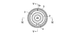
図1〜6は第1の実施の形態に係る保持部材1を示す。この保持部材1は、厚肉円筒状の基軸体2と、該基軸体2の先端側の外周を取り巻く、1条のスリット3a付きの薄肉円筒状の当接体3と、該基軸体2と当接体3とを繋ぐ連結体4とを有する。基軸体2の内孔2aは、基軸体2の後端から先端まで貫通しており、その内周面の全体に雌螺子2bが刻設されている。基軸体2は、その肉厚(内径(半径)と外径(半径)との差)が当接体3の肉厚よりも大きく、プラスチック管外周面の切削時に実質的に変形しない強度及び剛性を有している。
1 to 6 show a holding member 1 according to the first embodiment. The holding member 1 includes a thick cylindrical
当接体3は、基軸体2の先端側の外周を同軸状に取り巻いており、当接体3の内周面と基軸体2の外周面との間には、当接体3の縮径変形を許容する所定の間隙があいている。当接体3には、その軸心方向と平行方向に延在する1条のスリット3aが先端から後端まで縦断するように設けられている。当接体3が薄肉円筒状であるため、当接体3はスリット3aの幅wを拡縮させることにより縮径方向に弾性変形可能となっている。
The
当接体3の軸心を挟んで該スリット3aと反対側に連結体4が配置されている。この連結体4は、当接体3の先端から後端まで当接体3の軸心方向と平行方向に延在している。
A connecting
この保持部材1は、基軸体2、当接体3及び連結体4を含めて合成樹脂又は金属にて一体に形成されている。
The holding member 1 is integrally formed of synthetic resin or metal including the
この保持部材1によって保持されるプラスチック管5は、その内径が当接体3の外径よりも若干小さいものである。保持部材1によってプラスチック管5を保持するには、図3(a)のように、当接体3のスリット幅wを狭めるように当接体3を指先又は工具によって径方向に押し縮めてプラスチック管5内に差し込む。当接体3の押し縮め力を解放すると、当接体3がそれ自身の弾性力によって元の直径に戻ろうとしてプラスチック管5の内周面に押し付けられ、これにより、図3(b)及び図4〜6の通りプラスチック管5の一端が保持される。この保持部材1は、当接体3の外周面の全体又は大部分がプラスチック管5の内周面に密着するので、プラスチック管5の端部が保持部材1にしっかりと保持される。
The
図11は、この保持部材1によって保持されたプラスチック管5の端部外周面を切削治具10によって切削する方法の一例を示している。この切削治具10は、治具本体部11と、該治具本体部11から前方に突設された雄螺子棒12と、基端側が該治具本体部11に対し支軸13によって回動自在に取り付けられ、雄螺子棒12に沿って延在する複数本(通常は2〜4本)のアーム14と、各アーム14の先端側を互いに接近する求心方向に付勢するバネ(図示略)と、各アーム14の先端部の求心方向側に設けられたバイト(切削刃)15とを有している。なお、上記のバネは支軸13に巻回されたつる巻バネであるが、これに限定されない。雄螺子棒12の外周面には雄螺子が刻設されている。
FIG. 11 shows an example of a method of cutting the outer peripheral surface of the end portion of the
雄螺子棒12を保持部材1の基軸体2の内孔2aに螺合させ、治具本体部11を矢印θ方向にモータ(図示略)によって回すと、雄螺子棒12は図11の左方に螺進する。雄螺子棒12が所定長さ螺進すると、バイト15がプラスチック管5の最端部外周面に当接した図11の状態となる。
When the
この状態から治具本体部11をさらにθ方向に回すと、雄螺子棒12がさらに螺進し、バイト15がプラスチック管5の外周面を切削しながら螺旋方向に移動する。プラスチック管5の端部近傍の必要な範囲がバイト15で切削されるまで治具本体部11をθ方向に回転させる。その後、治具本体部11を反θ方向に回転させて雄螺子棒12を図11の右方向に退動させ、雄螺子棒12を内孔2aから離脱させ、切削治具10とプラスチック管5とを離反させる。
When the
保持部材1は、プラスチック管5の端部をしっかりと保持しているため、切削治具10を回転させたときに、該切削治具10がぐらついたりすることがなく、バイト15が一定の押圧力Fでプラスチック管5の外周面に押し付けられつつ螺旋方向に移動する。これにより、プラスチック管5の端部外周面が規定深さにて切削される。
Since the holding member 1 holds the end portion of the
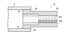
図7〜10は第2の実施の形態に係る保持部材21を示す。この保持部材21は、厚肉円筒状の基軸体22と、該基軸体22の先端側の外周から突設された複数片(この実施形態では4片)の連結体24と、各連結体24の先端部の外周面に設けられた当接体23とを有する。基軸体22の内孔22aは、基軸体22の後端から先端まで貫通しており、その内周面の全体に雌螺子22bが刻設されている。基軸体22は、その肉厚(内径(半径)と外径(半径)との差)が連結体24の肉厚よりも大きく、プラスチック管外周面の切削時に実質的に変形しない強度及び剛性を有している。
7 to 10 show a holding
各連結体24は、基軸体22の先端側の周方向に間隔を置いて配列されており、その先端側が求心方向に弾性的に変位可能となっている。当接体23は、連結体24の外周面から隆起する段状に設けられている。1片の連結体24の周方向の延在範囲である、基軸体22の軸心周りの中心角a(図8)は、10〜170°、中でも30〜120°、特に60〜90°が好ましい。当接体23の個数は、プラススチック管5の端部をしっかりと、均等な力で保持する為には多い方が好ましい。但し保持部材21の製造上の観点から、当接体23の数が多過ぎると工程が多くなり煩雑なるため、当接体23の個数は、一般的には2〜12個であることが好ましく、中でも3〜9個、特に4〜7個であることが好ましい。また当接体23における基軸体22の軸心周りの中心角a(図8)は、均等でも不均等であってもよいが、プラススチック管5の端部をしっかりと、均等な力で保持する為には、均等に近い方が好ましい。尚、図8では、当該中心角aが略均等となっている。
Each
この保持部材21は、基軸体22、当接体23及び連結体24を含めて合成樹脂又は金属にて一体に形成されている。
The holding
この保持部材21によって保持されるプラスチック管5は、その内径が当接体23の外接円の直径よりも若干小さいものである。保持部材21によってプラスチック管5を保持するには、図10のように、連結体24を求心方向に押してたわませ、当接体23をプラスチック管5内に差し込む。連結体24の押し縮め力を解放すると、連結体24がそれ自身の弾性力によって元の直径に戻ろうとして当接体23がプラスチック管5内周面に押し付けられ、これにより、図10の通りプラスチック管5の一端が保持される。この保持部材21は、当接体23の外周面の全体又は大部分がプラスチック管5の内周面に密着すると共に、4片の当接体23の合計の周長が長いので、プラスチック管5の端部が保持部材21にしっかりと保持される。
The inner diameter of the
この保持部材21によって保持されたプラスチック管5の端部外周面を切削治具10によって切削する方法は、図11と同様である。
The method of cutting the outer peripheral surface of the end portion of the
即ち、雄螺子棒12を保持部材21の基軸体2の内孔22aに螺合させ、治具本体部11を矢印θ方向にモータ(図示略)によって回し、雄螺子棒12が所定長さ螺進させ、バイト15をプラスチック管5の最端部外周面に当接させる。
That is, the
この状態から治具本体部11をさらにθ方向に回し、雄螺子棒12をさらに螺進させ、バイト15をプラスチック管5の外周面を切削しながら螺旋方向に移動させる。プラスチック管5の端部近傍の必要な範囲がバイト15で切削されるまで治具本体部11をθ方向に回転させる。その後、治具本体部11を反θ方向に回転させて雄螺子棒12を図11の右方向に退動させ、雄螺子棒12を内孔22aから離脱させ、切削治具10とプラスチック管5とを離反させる。
From this state, the jig
この実施形態でも、保持部材21がプラスチック管5の端部をしっかりと保持しているため、切削治具10を回転させたときに、該切削治具10がぐらついたりすることがなく、バイト15が一定の押圧力Fでプラスチック管5の外周面に押し付けられつつ螺旋方向に移動する。これにより、プラスチック管5の端部外周面が規定深さにて切削される。
Also in this embodiment, since the holding
上記実施の形態は本発明の一例であり、本発明は図示以外の形態とされてもよい。 The above-described embodiment is an example of the present invention, and the present invention may be configured other than illustrated.
1,21 保持部材
2,22 基軸体
3,23 当接体
3a スリット
4,24 連結体
5 プラスチック管
10 切削治具
11 治具本体
12 雄螺子棒
14 アーム
15 バイト
DESCRIPTION OF
Claims (5)
雌螺子が刻設された内孔が貫設された基軸体と、
該基軸体に対して連結体を介して一体となっている当接体と
を有しており、
該当接体はプラスチック管の中心に向う求心方向に弾性的に変位可能であり、該当接体の外周面がプラスチック管の内周面に弾性的に当接されることを特徴とするプラスチック管端部の保持部材。 A holding member for holding the end of the plastic tube,
A base shaft body through which an inner hole engraved with a female screw is formed;
A contact body integrated with the base shaft body via a connecting body,
The plastic pipe end characterized in that the contact body is elastically displaceable in a centripetal direction toward the center of the plastic tube, and an outer peripheral surface of the corresponding contact body is elastically contacted with an inner peripheral surface of the plastic tube. Part holding member.
該当接体に、基軸体の軸心方向と平行なスリットが設けられており、
当接体の軸心を挟んで該スリットと反対側が前記連結体を介して前記基軸体に連なっていることを特徴とするプラスチック管端部の保持部材。 In Claim 1, the base shaft body is cylindrical, and the contact body surrounds the tip end side of the base shaft body coaxially,
The contact body is provided with a slit parallel to the axial direction of the base shaft body,
A holding member for an end portion of a plastic tube, wherein the side opposite to the slit across the axis of the contact body is connected to the base shaft body via the connecting body.
各連結体は、基軸体の軸心周り方向に間隔をおいて配列されており、
各連結体は、その先端側が求心方向に弾性変形可能であり、
各連結体の先端側の外周面から前記当接体が放射方向に突設されていることを特徴とするプラスチック管端部の保持部材。 In Claim 1, the base shaft body is cylindrical, and a plurality of connecting bodies project from the outer peripheral side of the distal end surface of the base shaft body in a direction parallel to the axial direction of the base shaft body,
Each coupling body is arranged at intervals in the direction around the axis of the base shaft body,
Each connecting body is elastically deformable in the centripetal direction at the tip side,
A holding member for an end portion of a plastic pipe, wherein the contact body projects radially from the outer peripheral surface on the tip side of each connecting body.
該プラスチック管端部を請求項1ないし3のいずれか1項に記載の保持部材で保持し、
該保持部材の基軸体の内孔に該雄螺子棒を螺合させ、該バイトをプラスチック管端部の外周面に押し付け、該治具本体を軸心周りに回転させて螺進させ、前記バイトをプラスチック管外周面に沿って螺旋方向に移動させてプラスチック管端部の外周面を切削することを特徴とするプラスチック管端部外周面の切削方法。 A jig main body, a male screw rod projecting from the jig main body, an arm extending from the jig main body along the male screw rod, and a cutting tool provided on the tip side of the arm A method of cutting an outer peripheral surface of a plastic pipe end using a cutting jig,
The plastic pipe end is held by the holding member according to any one of claims 1 to 3,
The male screw rod is screwed into the inner hole of the base shaft body of the holding member, the cutting tool is pressed against the outer peripheral surface of the plastic tube end, the jig body is rotated around the axis, and is screwed. A method for cutting an outer peripheral surface of a plastic pipe end, wherein the outer peripheral surface of the plastic pipe end is cut by moving the screw along the outer peripheral surface of the plastic pipe in a spiral direction.
前記切削治具には、該アームを求心方向に付勢するためのバネが設けられており、
該バネの付勢力によって前記バイトをプラスチック管外周面に押し付けることを特徴とするプラスチック管端部周面の切削方法。 In Claim 4, the said arm is attached to the above-mentioned jig main part by the support axis so that rotation is possible,
The cutting jig is provided with a spring for urging the arm in the centripetal direction,
A cutting method of a peripheral surface of a plastic pipe, wherein the cutting tool is pressed against the outer peripheral surface of the plastic pipe by a biasing force of the spring.
Priority Applications (1)
| Application Number | Priority Date | Filing Date | Title |
|---|---|---|---|
| JP2015237630A JP2017100267A (en) | 2015-12-04 | 2015-12-04 | Holding member of pastic pipe end part and cutting method |
Applications Claiming Priority (1)
| Application Number | Priority Date | Filing Date | Title |
|---|---|---|---|
| JP2015237630A JP2017100267A (en) | 2015-12-04 | 2015-12-04 | Holding member of pastic pipe end part and cutting method |
Publications (1)
| Publication Number | Publication Date |
|---|---|
| JP2017100267A true JP2017100267A (en) | 2017-06-08 |
Family
ID=59016289
Family Applications (1)
| Application Number | Title | Priority Date | Filing Date |
|---|---|---|---|
| JP2015237630A Pending JP2017100267A (en) | 2015-12-04 | 2015-12-04 | Holding member of pastic pipe end part and cutting method |
Country Status (1)
| Country | Link |
|---|---|
| JP (1) | JP2017100267A (en) |
Cited By (1)
| Publication number | Priority date | Publication date | Assignee | Title |
|---|---|---|---|---|
| WO2018211785A1 (en) | 2017-05-19 | 2018-11-22 | 新東工業株式会社 | Casting mold shaping device and casting mold shaping method |
-
2015
- 2015-12-04 JP JP2015237630A patent/JP2017100267A/en active Pending
Cited By (1)
| Publication number | Priority date | Publication date | Assignee | Title |
|---|---|---|---|---|
| WO2018211785A1 (en) | 2017-05-19 | 2018-11-22 | 新東工業株式会社 | Casting mold shaping device and casting mold shaping method |
Similar Documents
| Publication | Publication Date | Title |
|---|---|---|
| JP2005301151A (en) | Optical contact unit and optical plug | |
| JP2006346781A (en) | Tool gripping structure | |
| JP2007319904A (en) | Core bar for bending double tube | |
| JP2017100267A (en) | Holding member of pastic pipe end part and cutting method | |
| WO2018047221A1 (en) | Tool chuck, tool-holding method and tool-detaching method | |
| JP2009142877A (en) | Tube end correcting tool | |
| JP4476263B2 (en) | Pipe fitting | |
| JP6851092B2 (en) | Tool holder tightening method and tool holder | |
| JP2010076411A (en) | Method for manufacturing ballpoint pen tip | |
| JP5953410B1 (en) | Pipe joint structure | |
| JP2019025512A (en) | Crimping apparatus for hose coupling metal fitting | |
| JP5778386B2 (en) | Lock ring for pipe joint, pipe joint, and manufacturing method of lock ring for pipe joint | |
| CN209986023U (en) | Reaming and shaping tool | |
| JP4428621B2 (en) | Incore | |
| JP4783043B2 (en) | Sheath tube cutter | |
| JP5748434B2 (en) | Tubing connection maintenance tool | |
| JP2019150550A (en) | Moxa rod holder, manufacturing method of same, moxibustion rod, and moxibustion device | |
| JP5670237B2 (en) | Optical fiber holding device and holding method | |
| JP7278752B2 (en) | Deburring tool, deburring method and deburring device | |
| JP3183616U (en) | Fusing joint joining jig | |
| JP4932353B2 (en) | Endoscope and repair method | |
| JP5426972B2 (en) | Pipe connection device and pipe joint | |
| JP4865419B2 (en) | Pipe fitting device | |
| JP2005351440A5 (en) | ||
| JP4476262B2 (en) | Pipe fitting |