WO2018207436A1 - 内燃機関の制御装置 - Google Patents
内燃機関の制御装置 Download PDFInfo
- Publication number
- WO2018207436A1 WO2018207436A1 PCT/JP2018/007442 JP2018007442W WO2018207436A1 WO 2018207436 A1 WO2018207436 A1 WO 2018207436A1 JP 2018007442 W JP2018007442 W JP 2018007442W WO 2018207436 A1 WO2018207436 A1 WO 2018207436A1
- Authority
- WO
- WIPO (PCT)
- Prior art keywords
- exhaust
- valve
- cylinder
- intake
- passage
- Prior art date
- Legal status (The legal status is an assumption and is not a legal conclusion. Google has not performed a legal analysis and makes no representation as to the accuracy of the status listed.)
- Ceased
Links
Images




Classifications
-
- F—MECHANICAL ENGINEERING; LIGHTING; HEATING; WEAPONS; BLASTING
- F02—COMBUSTION ENGINES; HOT-GAS OR COMBUSTION-PRODUCT ENGINE PLANTS
- F02M—SUPPLYING COMBUSTION ENGINES IN GENERAL WITH COMBUSTIBLE MIXTURES OR CONSTITUENTS THEREOF
- F02M35/00—Combustion-air cleaners, air intakes, intake silencers, or induction systems specially adapted for, or arranged on, internal-combustion engines
- F02M35/10—Air intakes; Induction systems
- F02M35/10209—Fluid connections to the air intake system; their arrangement of pipes, valves or the like
- F02M35/10222—Exhaust gas recirculation [EGR]; Positive crankcase ventilation [PCV]; Additional air admission, lubricant or fuel vapour admission
-
- F—MECHANICAL ENGINEERING; LIGHTING; HEATING; WEAPONS; BLASTING
- F02—COMBUSTION ENGINES; HOT-GAS OR COMBUSTION-PRODUCT ENGINE PLANTS
- F02D—CONTROLLING COMBUSTION ENGINES
- F02D13/00—Controlling the engine output power by varying inlet or exhaust valve operating characteristics, e.g. timing
- F02D13/02—Controlling the engine output power by varying inlet or exhaust valve operating characteristics, e.g. timing during engine operation
- F02D13/0203—Variable control of intake and exhaust valves
- F02D13/0215—Variable control of intake and exhaust valves changing the valve timing only
-
- F—MECHANICAL ENGINEERING; LIGHTING; HEATING; WEAPONS; BLASTING
- F01—MACHINES OR ENGINES IN GENERAL; ENGINE PLANTS IN GENERAL; STEAM ENGINES
- F01L—CYCLICALLY OPERATING VALVES FOR MACHINES OR ENGINES
- F01L1/00—Valve-gear or valve arrangements, e.g. lift-valve gear
- F01L1/02—Valve drive
- F01L1/04—Valve drive by means of cams, camshafts, cam discs, eccentrics or the like
- F01L1/047—Camshafts
-
- F—MECHANICAL ENGINEERING; LIGHTING; HEATING; WEAPONS; BLASTING
- F01—MACHINES OR ENGINES IN GENERAL; ENGINE PLANTS IN GENERAL; STEAM ENGINES
- F01L—CYCLICALLY OPERATING VALVES FOR MACHINES OR ENGINES
- F01L1/00—Valve-gear or valve arrangements, e.g. lift-valve gear
- F01L1/34—Valve-gear or valve arrangements, e.g. lift-valve gear characterised by the provision of means for changing the timing of the valves without changing the duration of opening and without affecting the magnitude of the valve lift
- F01L1/344—Valve-gear or valve arrangements, e.g. lift-valve gear characterised by the provision of means for changing the timing of the valves without changing the duration of opening and without affecting the magnitude of the valve lift changing the angular relationship between crankshaft and camshaft, e.g. using helicoidal gear
- F01L1/3442—Valve-gear or valve arrangements, e.g. lift-valve gear characterised by the provision of means for changing the timing of the valves without changing the duration of opening and without affecting the magnitude of the valve lift changing the angular relationship between crankshaft and camshaft, e.g. using helicoidal gear using hydraulic chambers with variable volume to transmit the rotating force
-
- F—MECHANICAL ENGINEERING; LIGHTING; HEATING; WEAPONS; BLASTING
- F01—MACHINES OR ENGINES IN GENERAL; ENGINE PLANTS IN GENERAL; STEAM ENGINES
- F01N—GAS-FLOW SILENCERS OR EXHAUST APPARATUS FOR MACHINES OR ENGINES IN GENERAL; GAS-FLOW SILENCERS OR EXHAUST APPARATUS FOR INTERNAL-COMBUSTION ENGINES
- F01N13/00—Exhaust or silencing apparatus characterised by constructional features
- F01N13/08—Other arrangements or adaptations of exhaust conduits
- F01N13/10—Other arrangements or adaptations of exhaust conduits of exhaust manifolds
-
- F—MECHANICAL ENGINEERING; LIGHTING; HEATING; WEAPONS; BLASTING
- F01—MACHINES OR ENGINES IN GENERAL; ENGINE PLANTS IN GENERAL; STEAM ENGINES
- F01N—GAS-FLOW SILENCERS OR EXHAUST APPARATUS FOR MACHINES OR ENGINES IN GENERAL; GAS-FLOW SILENCERS OR EXHAUST APPARATUS FOR INTERNAL-COMBUSTION ENGINES
- F01N3/00—Exhaust or silencing apparatus having means for purifying, rendering innocuous, or otherwise treating exhaust
- F01N3/08—Exhaust or silencing apparatus having means for purifying, rendering innocuous, or otherwise treating exhaust for rendering innocuous
- F01N3/0807—Exhaust or silencing apparatus having means for purifying, rendering innocuous, or otherwise treating exhaust for rendering innocuous by using absorbents or adsorbents
- F01N3/0828—Exhaust or silencing apparatus having means for purifying, rendering innocuous, or otherwise treating exhaust for rendering innocuous by using absorbents or adsorbents characterised by the absorbed or adsorbed substances
- F01N3/0835—Hydrocarbons
-
- F—MECHANICAL ENGINEERING; LIGHTING; HEATING; WEAPONS; BLASTING
- F01—MACHINES OR ENGINES IN GENERAL; ENGINE PLANTS IN GENERAL; STEAM ENGINES
- F01N—GAS-FLOW SILENCERS OR EXHAUST APPARATUS FOR MACHINES OR ENGINES IN GENERAL; GAS-FLOW SILENCERS OR EXHAUST APPARATUS FOR INTERNAL-COMBUSTION ENGINES
- F01N3/00—Exhaust or silencing apparatus having means for purifying, rendering innocuous, or otherwise treating exhaust
- F01N3/08—Exhaust or silencing apparatus having means for purifying, rendering innocuous, or otherwise treating exhaust for rendering innocuous
- F01N3/10—Exhaust or silencing apparatus having means for purifying, rendering innocuous, or otherwise treating exhaust for rendering innocuous by thermal or catalytic conversion of noxious components of exhaust
- F01N3/103—Oxidation catalysts for HC and CO only
-
- F—MECHANICAL ENGINEERING; LIGHTING; HEATING; WEAPONS; BLASTING
- F02—COMBUSTION ENGINES; HOT-GAS OR COMBUSTION-PRODUCT ENGINE PLANTS
- F02D—CONTROLLING COMBUSTION ENGINES
- F02D13/00—Controlling the engine output power by varying inlet or exhaust valve operating characteristics, e.g. timing
- F02D13/02—Controlling the engine output power by varying inlet or exhaust valve operating characteristics, e.g. timing during engine operation
- F02D13/0203—Variable control of intake and exhaust valves
- F02D13/0215—Variable control of intake and exhaust valves changing the valve timing only
- F02D13/0219—Variable control of intake and exhaust valves changing the valve timing only by shifting the phase, i.e. the opening periods of the valves are constant
-
- F—MECHANICAL ENGINEERING; LIGHTING; HEATING; WEAPONS; BLASTING
- F02—COMBUSTION ENGINES; HOT-GAS OR COMBUSTION-PRODUCT ENGINE PLANTS
- F02D—CONTROLLING COMBUSTION ENGINES
- F02D13/00—Controlling the engine output power by varying inlet or exhaust valve operating characteristics, e.g. timing
- F02D13/02—Controlling the engine output power by varying inlet or exhaust valve operating characteristics, e.g. timing during engine operation
- F02D13/0261—Controlling the valve overlap
-
- F—MECHANICAL ENGINEERING; LIGHTING; HEATING; WEAPONS; BLASTING
- F02—COMBUSTION ENGINES; HOT-GAS OR COMBUSTION-PRODUCT ENGINE PLANTS
- F02D—CONTROLLING COMBUSTION ENGINES
- F02D41/00—Electrical control of supply of combustible mixture or its constituents
- F02D41/0025—Controlling engines characterised by use of non-liquid fuels, pluralities of fuels, or non-fuel substances added to the combustible mixtures
- F02D41/0047—Controlling exhaust gas recirculation [EGR]
- F02D41/006—Controlling exhaust gas recirculation [EGR] using internal EGR
-
- F—MECHANICAL ENGINEERING; LIGHTING; HEATING; WEAPONS; BLASTING
- F02—COMBUSTION ENGINES; HOT-GAS OR COMBUSTION-PRODUCT ENGINE PLANTS
- F02D—CONTROLLING COMBUSTION ENGINES
- F02D41/00—Electrical control of supply of combustible mixture or its constituents
- F02D41/008—Controlling each cylinder individually
-
- F—MECHANICAL ENGINEERING; LIGHTING; HEATING; WEAPONS; BLASTING
- F02—COMBUSTION ENGINES; HOT-GAS OR COMBUSTION-PRODUCT ENGINE PLANTS
- F02M—SUPPLYING COMBUSTION ENGINES IN GENERAL WITH COMBUSTIBLE MIXTURES OR CONSTITUENTS THEREOF
- F02M26/00—Engine-pertinent apparatus for adding exhaust gases to combustion-air, main fuel or fuel-air mixture, e.g. by exhaust gas recirculation [EGR] systems
- F02M26/13—Arrangement or layout of EGR passages, e.g. in relation to specific engine parts or for incorporation of accessories
- F02M26/14—Arrangement or layout of EGR passages, e.g. in relation to specific engine parts or for incorporation of accessories in relation to the exhaust system
-
- F—MECHANICAL ENGINEERING; LIGHTING; HEATING; WEAPONS; BLASTING
- F02—COMBUSTION ENGINES; HOT-GAS OR COMBUSTION-PRODUCT ENGINE PLANTS
- F02M—SUPPLYING COMBUSTION ENGINES IN GENERAL WITH COMBUSTIBLE MIXTURES OR CONSTITUENTS THEREOF
- F02M26/00—Engine-pertinent apparatus for adding exhaust gases to combustion-air, main fuel or fuel-air mixture, e.g. by exhaust gas recirculation [EGR] systems
- F02M26/52—Systems for actuating EGR valves
- F02M26/53—Systems for actuating EGR valves using electric actuators, e.g. solenoids
-
- F—MECHANICAL ENGINEERING; LIGHTING; HEATING; WEAPONS; BLASTING
- F01—MACHINES OR ENGINES IN GENERAL; ENGINE PLANTS IN GENERAL; STEAM ENGINES
- F01L—CYCLICALLY OPERATING VALVES FOR MACHINES OR ENGINES
- F01L1/00—Valve-gear or valve arrangements, e.g. lift-valve gear
- F01L1/02—Valve drive
- F01L1/04—Valve drive by means of cams, camshafts, cam discs, eccentrics or the like
- F01L1/047—Camshafts
- F01L1/053—Camshafts overhead type
- F01L2001/0537—Double overhead camshafts [DOHC]
-
- F—MECHANICAL ENGINEERING; LIGHTING; HEATING; WEAPONS; BLASTING
- F01—MACHINES OR ENGINES IN GENERAL; ENGINE PLANTS IN GENERAL; STEAM ENGINES
- F01L—CYCLICALLY OPERATING VALVES FOR MACHINES OR ENGINES
- F01L1/00—Valve-gear or valve arrangements, e.g. lift-valve gear
- F01L1/34—Valve-gear or valve arrangements, e.g. lift-valve gear characterised by the provision of means for changing the timing of the valves without changing the duration of opening and without affecting the magnitude of the valve lift
- F01L1/344—Valve-gear or valve arrangements, e.g. lift-valve gear characterised by the provision of means for changing the timing of the valves without changing the duration of opening and without affecting the magnitude of the valve lift changing the angular relationship between crankshaft and camshaft, e.g. using helicoidal gear
- F01L1/3442—Valve-gear or valve arrangements, e.g. lift-valve gear characterised by the provision of means for changing the timing of the valves without changing the duration of opening and without affecting the magnitude of the valve lift changing the angular relationship between crankshaft and camshaft, e.g. using helicoidal gear using hydraulic chambers with variable volume to transmit the rotating force
- F01L2001/34423—Details relating to the hydraulic feeding circuit
- F01L2001/34426—Oil control valves
- F01L2001/3443—Solenoid driven oil control valves
-
- F—MECHANICAL ENGINEERING; LIGHTING; HEATING; WEAPONS; BLASTING
- F01—MACHINES OR ENGINES IN GENERAL; ENGINE PLANTS IN GENERAL; STEAM ENGINES
- F01L—CYCLICALLY OPERATING VALVES FOR MACHINES OR ENGINES
- F01L1/00—Valve-gear or valve arrangements, e.g. lift-valve gear
- F01L1/34—Valve-gear or valve arrangements, e.g. lift-valve gear characterised by the provision of means for changing the timing of the valves without changing the duration of opening and without affecting the magnitude of the valve lift
- F01L1/344—Valve-gear or valve arrangements, e.g. lift-valve gear characterised by the provision of means for changing the timing of the valves without changing the duration of opening and without affecting the magnitude of the valve lift changing the angular relationship between crankshaft and camshaft, e.g. using helicoidal gear
- F01L1/3442—Valve-gear or valve arrangements, e.g. lift-valve gear characterised by the provision of means for changing the timing of the valves without changing the duration of opening and without affecting the magnitude of the valve lift changing the angular relationship between crankshaft and camshaft, e.g. using helicoidal gear using hydraulic chambers with variable volume to transmit the rotating force
- F01L2001/3445—Details relating to the hydraulic means for changing the angular relationship
- F01L2001/34453—Locking means between driving and driven members
- F01L2001/34456—Locking in only one position
-
- F—MECHANICAL ENGINEERING; LIGHTING; HEATING; WEAPONS; BLASTING
- F01—MACHINES OR ENGINES IN GENERAL; ENGINE PLANTS IN GENERAL; STEAM ENGINES
- F01L—CYCLICALLY OPERATING VALVES FOR MACHINES OR ENGINES
- F01L1/00—Valve-gear or valve arrangements, e.g. lift-valve gear
- F01L1/34—Valve-gear or valve arrangements, e.g. lift-valve gear characterised by the provision of means for changing the timing of the valves without changing the duration of opening and without affecting the magnitude of the valve lift
- F01L1/344—Valve-gear or valve arrangements, e.g. lift-valve gear characterised by the provision of means for changing the timing of the valves without changing the duration of opening and without affecting the magnitude of the valve lift changing the angular relationship between crankshaft and camshaft, e.g. using helicoidal gear
- F01L1/3442—Valve-gear or valve arrangements, e.g. lift-valve gear characterised by the provision of means for changing the timing of the valves without changing the duration of opening and without affecting the magnitude of the valve lift changing the angular relationship between crankshaft and camshaft, e.g. using helicoidal gear using hydraulic chambers with variable volume to transmit the rotating force
- F01L2001/3445—Details relating to the hydraulic means for changing the angular relationship
- F01L2001/34453—Locking means between driving and driven members
- F01L2001/34463—Locking position intermediate between most retarded and most advanced positions
-
- F—MECHANICAL ENGINEERING; LIGHTING; HEATING; WEAPONS; BLASTING
- F01—MACHINES OR ENGINES IN GENERAL; ENGINE PLANTS IN GENERAL; STEAM ENGINES
- F01L—CYCLICALLY OPERATING VALVES FOR MACHINES OR ENGINES
- F01L1/00—Valve-gear or valve arrangements, e.g. lift-valve gear
- F01L1/34—Valve-gear or valve arrangements, e.g. lift-valve gear characterised by the provision of means for changing the timing of the valves without changing the duration of opening and without affecting the magnitude of the valve lift
- F01L1/344—Valve-gear or valve arrangements, e.g. lift-valve gear characterised by the provision of means for changing the timing of the valves without changing the duration of opening and without affecting the magnitude of the valve lift changing the angular relationship between crankshaft and camshaft, e.g. using helicoidal gear
- F01L1/3442—Valve-gear or valve arrangements, e.g. lift-valve gear characterised by the provision of means for changing the timing of the valves without changing the duration of opening and without affecting the magnitude of the valve lift changing the angular relationship between crankshaft and camshaft, e.g. using helicoidal gear using hydraulic chambers with variable volume to transmit the rotating force
- F01L2001/3445—Details relating to the hydraulic means for changing the angular relationship
- F01L2001/34453—Locking means between driving and driven members
- F01L2001/34466—Locking means between driving and driven members with multiple locking devices
-
- F—MECHANICAL ENGINEERING; LIGHTING; HEATING; WEAPONS; BLASTING
- F01—MACHINES OR ENGINES IN GENERAL; ENGINE PLANTS IN GENERAL; STEAM ENGINES
- F01L—CYCLICALLY OPERATING VALVES FOR MACHINES OR ENGINES
- F01L1/00—Valve-gear or valve arrangements, e.g. lift-valve gear
- F01L1/34—Valve-gear or valve arrangements, e.g. lift-valve gear characterised by the provision of means for changing the timing of the valves without changing the duration of opening and without affecting the magnitude of the valve lift
- F01L1/344—Valve-gear or valve arrangements, e.g. lift-valve gear characterised by the provision of means for changing the timing of the valves without changing the duration of opening and without affecting the magnitude of the valve lift changing the angular relationship between crankshaft and camshaft, e.g. using helicoidal gear
- F01L1/3442—Valve-gear or valve arrangements, e.g. lift-valve gear characterised by the provision of means for changing the timing of the valves without changing the duration of opening and without affecting the magnitude of the valve lift changing the angular relationship between crankshaft and camshaft, e.g. using helicoidal gear using hydraulic chambers with variable volume to transmit the rotating force
- F01L2001/3445—Details relating to the hydraulic means for changing the angular relationship
- F01L2001/34453—Locking means between driving and driven members
- F01L2001/34473—Lock movement perpendicular to camshaft axis
-
- F—MECHANICAL ENGINEERING; LIGHTING; HEATING; WEAPONS; BLASTING
- F01—MACHINES OR ENGINES IN GENERAL; ENGINE PLANTS IN GENERAL; STEAM ENGINES
- F01L—CYCLICALLY OPERATING VALVES FOR MACHINES OR ENGINES
- F01L1/00—Valve-gear or valve arrangements, e.g. lift-valve gear
- F01L1/34—Valve-gear or valve arrangements, e.g. lift-valve gear characterised by the provision of means for changing the timing of the valves without changing the duration of opening and without affecting the magnitude of the valve lift
- F01L1/344—Valve-gear or valve arrangements, e.g. lift-valve gear characterised by the provision of means for changing the timing of the valves without changing the duration of opening and without affecting the magnitude of the valve lift changing the angular relationship between crankshaft and camshaft, e.g. using helicoidal gear
- F01L1/3442—Valve-gear or valve arrangements, e.g. lift-valve gear characterised by the provision of means for changing the timing of the valves without changing the duration of opening and without affecting the magnitude of the valve lift changing the angular relationship between crankshaft and camshaft, e.g. using helicoidal gear using hydraulic chambers with variable volume to transmit the rotating force
- F01L2001/3445—Details relating to the hydraulic means for changing the angular relationship
- F01L2001/34479—Sealing of phaser devices
-
- F—MECHANICAL ENGINEERING; LIGHTING; HEATING; WEAPONS; BLASTING
- F01—MACHINES OR ENGINES IN GENERAL; ENGINE PLANTS IN GENERAL; STEAM ENGINES
- F01L—CYCLICALLY OPERATING VALVES FOR MACHINES OR ENGINES
- F01L1/00—Valve-gear or valve arrangements, e.g. lift-valve gear
- F01L1/34—Valve-gear or valve arrangements, e.g. lift-valve gear characterised by the provision of means for changing the timing of the valves without changing the duration of opening and without affecting the magnitude of the valve lift
- F01L1/344—Valve-gear or valve arrangements, e.g. lift-valve gear characterised by the provision of means for changing the timing of the valves without changing the duration of opening and without affecting the magnitude of the valve lift changing the angular relationship between crankshaft and camshaft, e.g. using helicoidal gear
- F01L1/3442—Valve-gear or valve arrangements, e.g. lift-valve gear characterised by the provision of means for changing the timing of the valves without changing the duration of opening and without affecting the magnitude of the valve lift changing the angular relationship between crankshaft and camshaft, e.g. using helicoidal gear using hydraulic chambers with variable volume to transmit the rotating force
- F01L2001/3445—Details relating to the hydraulic means for changing the angular relationship
- F01L2001/34483—Phaser return springs
-
- F—MECHANICAL ENGINEERING; LIGHTING; HEATING; WEAPONS; BLASTING
- F01—MACHINES OR ENGINES IN GENERAL; ENGINE PLANTS IN GENERAL; STEAM ENGINES
- F01L—CYCLICALLY OPERATING VALVES FOR MACHINES OR ENGINES
- F01L1/00—Valve-gear or valve arrangements, e.g. lift-valve gear
- F01L1/34—Valve-gear or valve arrangements, e.g. lift-valve gear characterised by the provision of means for changing the timing of the valves without changing the duration of opening and without affecting the magnitude of the valve lift
- F01L1/344—Valve-gear or valve arrangements, e.g. lift-valve gear characterised by the provision of means for changing the timing of the valves without changing the duration of opening and without affecting the magnitude of the valve lift changing the angular relationship between crankshaft and camshaft, e.g. using helicoidal gear
- F01L2001/34486—Location and number of the means for changing the angular relationship
- F01L2001/34496—Two phasers on different camshafts
-
- F—MECHANICAL ENGINEERING; LIGHTING; HEATING; WEAPONS; BLASTING
- F01—MACHINES OR ENGINES IN GENERAL; ENGINE PLANTS IN GENERAL; STEAM ENGINES
- F01L—CYCLICALLY OPERATING VALVES FOR MACHINES OR ENGINES
- F01L2250/00—Camshaft drives characterised by their transmission means
- F01L2250/02—Camshaft drives characterised by their transmission means the camshaft being driven by chains
-
- F—MECHANICAL ENGINEERING; LIGHTING; HEATING; WEAPONS; BLASTING
- F02—COMBUSTION ENGINES; HOT-GAS OR COMBUSTION-PRODUCT ENGINE PLANTS
- F02D—CONTROLLING COMBUSTION ENGINES
- F02D2200/00—Input parameters for engine control
- F02D2200/02—Input parameters for engine control the parameters being related to the engine
- F02D2200/04—Engine intake system parameters
- F02D2200/0406—Intake manifold pressure
-
- F—MECHANICAL ENGINEERING; LIGHTING; HEATING; WEAPONS; BLASTING
- F02—COMBUSTION ENGINES; HOT-GAS OR COMBUSTION-PRODUCT ENGINE PLANTS
- F02D—CONTROLLING COMBUSTION ENGINES
- F02D2200/00—Input parameters for engine control
- F02D2200/02—Input parameters for engine control the parameters being related to the engine
- F02D2200/04—Engine intake system parameters
- F02D2200/0414—Air temperature
-
- F—MECHANICAL ENGINEERING; LIGHTING; HEATING; WEAPONS; BLASTING
- F02—COMBUSTION ENGINES; HOT-GAS OR COMBUSTION-PRODUCT ENGINE PLANTS
- F02D—CONTROLLING COMBUSTION ENGINES
- F02D41/00—Electrical control of supply of combustible mixture or its constituents
- F02D41/02—Circuit arrangements for generating control signals
- F02D41/18—Circuit arrangements for generating control signals by measuring intake air flow
-
- Y—GENERAL TAGGING OF NEW TECHNOLOGICAL DEVELOPMENTS; GENERAL TAGGING OF CROSS-SECTIONAL TECHNOLOGIES SPANNING OVER SEVERAL SECTIONS OF THE IPC; TECHNICAL SUBJECTS COVERED BY FORMER USPC CROSS-REFERENCE ART COLLECTIONS [XRACs] AND DIGESTS
- Y02—TECHNOLOGIES OR APPLICATIONS FOR MITIGATION OR ADAPTATION AGAINST CLIMATE CHANGE
- Y02T—CLIMATE CHANGE MITIGATION TECHNOLOGIES RELATED TO TRANSPORTATION
- Y02T10/00—Road transport of goods or passengers
- Y02T10/10—Internal combustion engine [ICE] based vehicles
- Y02T10/12—Improving ICE efficiencies
-
- Y—GENERAL TAGGING OF NEW TECHNOLOGICAL DEVELOPMENTS; GENERAL TAGGING OF CROSS-SECTIONAL TECHNOLOGIES SPANNING OVER SEVERAL SECTIONS OF THE IPC; TECHNICAL SUBJECTS COVERED BY FORMER USPC CROSS-REFERENCE ART COLLECTIONS [XRACs] AND DIGESTS
- Y02—TECHNOLOGIES OR APPLICATIONS FOR MITIGATION OR ADAPTATION AGAINST CLIMATE CHANGE
- Y02T—CLIMATE CHANGE MITIGATION TECHNOLOGIES RELATED TO TRANSPORTATION
- Y02T10/00—Road transport of goods or passengers
- Y02T10/10—Internal combustion engine [ICE] based vehicles
- Y02T10/40—Engine management systems
Definitions
- the present invention relates to a control device for an internal combustion engine, and more particularly to a technique for suppressing the emission of unburned HC.
- the amount of fuel injected into the combustion chamber is large in order to reliably execute the first combustion (first explosion) in the cylinder, and unburned HC (hydrocarbon) due to incomplete combustion tends to increase. Further, when the engine is started, the catalyst for purifying the unburned HC is not warmed and activated, so that the unburned HC is easily discharged to the outside.
- Patent Document 1 the opening timing of the intake valve and the opening timing of the exhaust valve are overlapped between the first explosion of each cylinder and the next combustion, so that the second cycle (hereinafter, intake, compression, expansion, 4 cycles of exhaust are expressed as “one cycle.”
- exhaust containing unburned HC present in the exhaust passage is returned to the combustion chamber and recombusted to reduce the amount of unburned HC emitted.
- a technique called EGR exhaust gas recirculation
- a technique is disclosed in which after the temperature of the exhaust passage is increased, the exhaust valve is advanced to open the exhaust valve at the end of the expansion stroke, and combustion is continued in the exhaust passage in addition to the combustion chamber. . Thereby, the catalyst is activated early and the purification efficiency of unburned HC is improved.
- Patent Document 2 discloses a technique for setting the fuel injection amount for the second and subsequent cycles based on the intake pressure of each cylinder in the first cycle including the first explosion and the amount of change in the intake pressure. Thereby, the setting of the fuel injection amount in consideration of the fuel adhering to the exhaust passage and the combustion chamber is executed after the second cycle, and the amount of unburned HC discharged due to incomplete combustion is reduced.
- JP 2002-206436 A Japanese Patent Laid-Open No. 2001-221087
- control device for a conventional internal combustion engine can reduce the amount of unburned HC emission only after the second cycle after the first cycle including the first explosion. In other words, at the first explosion with a large amount of fuel injection, the emission of unburned HC cannot be reliably suppressed, and there is room for improvement.
- a characteristic configuration of a control device for an internal combustion engine includes a plurality of cylinders including a combustion chamber, a piston that moves between a top dead center position and a bottom dead center position inside the cylinder, and a crankshaft connected to the piston.
- An intake valve and an exhaust passage connected to the combustion chamber of each of the cylinders; an intake valve provided separately at a connection port between the combustion chamber of each of the cylinders and the intake passage and the exhaust passage;
- An internal combustion engine having an exhaust valve, an intake valve and an exhaust shaft respectively connected to the intake valve and the exhaust valve; a drive-side rotator that rotates synchronously with the crankshaft; and rotation of the drive-side rotator
- a driven-side rotating body that is arranged to be rotatable relative to the driving-side rotating body on an axial center and a coaxial core, and rotates integrally with the exhaust shaft; and a relative rotational position of the driving-side rotating body and the driven-side rotating body
- the opening timing of the intake valve overlaps the opening timing of the exhaust valve, and the intake passage of any of the cylinders in the exhaust stroke and the intake air at the same time as the exhaust stroke
- a bypass passage is provided to connect the exhaust passages of the other cylinders in the stroke.
- a bypass passage is provided that connects an exhaust passage of any cylinder in the exhaust stroke and an exhaust passage of another cylinder in the intake stroke at the same time as the exhaust stroke.
- the exhaust gas containing unburned HC in any cylinder is introduced into the combustion chamber of another cylinder in a state where the exhaust valve is opened during the overlap period.
- exhaust containing unburned HC present in the exhaust passages of other cylinders is returned to the combustion chamber, but also exhaust containing unburned HC present in the exhaust passages of any cylinder is burned by other cylinders. Introduced into the room.
- the unburned HC discharged from one of the cylinders is introduced into the combustion chamber of the other cylinder and recombusted.
- the amount of unburned HC emissions can be further reduced.
- control device for the internal combustion engine that can further suppress the emission of unburned HC could be provided.
- bypass passage allows the flow of exhaust from the exhaust passage of any one of the cylinders to the exhaust passage of the other cylinder, and any one of the bypass passages from the exhaust passage of the other cylinders.
- a check valve is provided to block the flow of exhaust gas to the exhaust passage of the cylinder.
- Another configuration is that an electromagnetic valve is provided in the bypass passage.
- the exhaust valve opened after the first combustion is performed from the time before the first combustion is performed in the combustion chamber immediately after cranking in any of the cylinders during the predetermined period. This is a period until it is closed for the first time, and the solenoid valve is open during the predetermined period and is closed when the predetermined period ends.
- the charging efficiency of the internal combustion engine is equal to or higher than a predetermined value
- the rotation speed of the internal combustion engine is a high load low rotation state where the rotation speed is equal to or lower than a predetermined rotation speed.
- the electromagnetic valve is open only during the predetermined period.
- ⁇ Intake pressure is high in the high load and low rotation range, so it is difficult to introduce internal EGR into the combustion chamber of the cylinder. Therefore, if the solenoid valve is opened during the period of high load and low rotation as in this configuration, the exhaust having high pressure in the early stage of the exhaust stroke in the exhaust passage of any cylinder is exhausted in the overlap period. Is introduced into the exhaust passage of another cylinder that has opened. As a result, the flow rate of the internal EGR returned to the combustion chambers of the other cylinders increases, so that the internal EGR can be reliably introduced into the combustion chambers. Therefore, discharge of unburned HC can be suppressed.
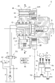
- FIG. 3 is a cross-sectional view taken along line III-III in FIG. 2 and is a cross-sectional view at an intermediate lock phase of the valve timing control device. It is sectional drawing in the most advance angle phase of a valve opening / closing timing control apparatus. It is a conceptual diagram of the bypass passage provided in the exhaust passage. It is a figure which shows sequentially the action
- an engine E an example of an internal combustion engine
- an intake-side valve opening / closing timing control device A for setting the opening / closing timing of an intake valve Va of the engine E
- the control device for the internal combustion engine includes an exhaust valve opening / closing timing control device B for setting the opening / closing timing and an engine control unit (ECU) 50 for controlling the engine E.
- ECU engine control unit
- the engine E shown in FIG. 1 is provided in a vehicle such as a passenger car.
- the engine E includes four cylinders K (cylinders), a piston 4, a crankshaft 1, an intake passage 11, an exhaust passage 12, an intake valve Va, an exhaust valve Vb, and an intake shaft 7 (intake side camshaft). ) And an exhaust shaft 8 (exhaust side camshaft).
- the cylinder K is composed of an inner peripheral wall of the cylinder block 2 and a bottom wall of the cylinder head 3.
- the cylinder K slidably accommodates the piston 4 and is a combustion chamber as a space surrounded by the crown surface of the piston 4 at the top dead center position, the inner peripheral wall of the cylinder block 2 and the bottom wall of the cylinder head 3.
- the cylinder head 3 is provided with an injector 9 and a spark plug 10 for injecting fuel into the combustion chamber Ka.
- the piston 4 moves between the top dead center position and the bottom dead center position inside the cylinder K.
- the crankshaft 1 is supported by a cylinder block 2 and is connected to a piston 4 by a connecting rod 5.
- the intake passage 11 is a flow path from a surge tank (not shown) of the intake manifold 11a connected to the cylinder head 3 to the intake valve Va, and is connected to the combustion chamber Ka of the cylinder K.
- the intake valve Va is supported by the cylinder head 3 and is a valve body that opens and closes a connection port (intake port) between the combustion chamber Ka and the intake passage 11.
- the intake manifold 11a is provided with an intake air temperature sensor 53, an intake pressure sensor 54, and an air flow meter 55.
- the exhaust passage 12 is a flow path from the merging portion T of the exhaust manifold 12 a connected to the cylinder head 3 to the exhaust valve Vb, and is connected to the combustion chamber Ka of the cylinder K. Yes.
- the exhaust valve Vb is supported by the cylinder head 3 and is a valve body that opens and closes a connection port (exhaust port) between the combustion chamber Ka and the exhaust passage 12.
- the four exhaust passages 12 connected to each cylinder K are merged at one merging portion T, but the combination of the exhaust passages 12 connected to any two cylinders K is a merging portion.
- the two exhaust passages 12 may be joined again after joining at T.
- a catalytic converter 13 for purifying combustion gas (exhaust gas, hereinafter referred to as “combustion gas”) is provided on the downstream side of the junction T where the exhaust passage 12 joins. Since the internal temperature of the catalytic converter 13 is low when the engine E is started, unburned HC may be discharged without being processed by the catalytic converter 13.
- a bypass passage 18 that connects the two exhaust passages 12 is provided. Since the engine E of the present embodiment is composed of four cylinders K, four bypass passages 18 are provided. These bypass passages 18 connect the exhaust passages 12 of any cylinder K in the exhaust stroke and the exhaust passages 12 of other cylinders K in the intake stroke at the same time as the exhaust stroke. Specifically, the exhaust passages 12 of the first cylinder K1 and the second cylinder K2, the first cylinder K1 and the third cylinder K3, the second cylinder K2 and the fourth cylinder K4, and the third cylinder K3 and the fourth cylinder K4. There are four bypass passages 18 connecting the two. Thereby, the combustion gas containing unburned HC discharged in the exhaust stroke of any cylinder K is introduced into the combustion chamber Ka of the other cylinder K, and the unburned HC is reburned.
- the four bypass passages 18 allow the combustion gas to flow from the exhaust passage 12 of one of the cylinders K to the exhaust passage 12 of the other cylinder K, and from the exhaust passage 12 of the other cylinder K to any one of the cylinders K.
- Check valves 19 are provided to block the flow of combustion gas to the exhaust passage 12. Specifically, the check valve 19 allows the combustion gas to flow from the first cylinder K1 in the exhaust stroke to the second cylinder K2 in the intake stroke at the same time, and from the second cylinder K2 in the exhaust stroke. At the same time, the flow of combustion gas to the first cylinder K1 in the expansion stroke is shut off (see FIG. 7).
- the check valve 19 allows the flow of combustion gas from the second cylinder K2 to the fourth cylinder K4 and blocks the flow of combustion gas from the fourth cylinder K4 to the second cylinder K2. Further, the check valve 19 allows the flow of combustion gas from the third cylinder K3 to the first cylinder K1, and blocks the flow of combustion gas from the first cylinder K1 to the third cylinder K3. Further, the check valve 19 allows the flow of combustion gas from the fourth cylinder K4 to the third cylinder K3 and blocks the flow of combustion gas from the third cylinder K3 to the fourth cylinder K4. This prevents inconvenience that the exhaust gas existing in the exhaust passage 12 of the other cylinder K in the exhaust stroke flows into the combustion chamber Ka of any cylinder K in the expansion stroke to reduce the combustion stability. be able to.
- electromagnetic valves 28 are provided in the four bypass passages 18 upstream of the check valve 19 in the direction in which the combustion gas flows. Regardless of whether the check valve 19 is opened or closed, the arrangement of the electromagnetic valve 28 makes it possible to shut off the flow of the combustion gas by closing the electromagnetic valve 28. As a result, since the check valve 19 does not repeat opening and closing, the life of the check valve 19 can be extended.
- the solenoid valve 28 may be provided on the downstream side of the check valve 19 in the direction in which the combustion gas flows on the bypass passage 18.
- the intake shaft 7 is supported by the cylinder head 3 and connected to the intake valve Va.
- the exhaust shaft 8 is supported by the cylinder head 3 and is connected to the exhaust valve Vb.
- the intake valve Va is opened and closed
- the exhaust valve Vb is opened and closed.
- the engine E includes a starter motor 15 that transmits a driving torque to the crankshaft 1 and a shaft sensor 16 that detects a rotation angle and a rotation speed at a position near the crankshaft 1.
- a phase sensor 17 for detecting the relative rotational phase between the external rotor 20 and the internal rotor 30 is provided in the vicinity of the exhaust-side valve opening / closing timing control device B described later.
- valve opening / closing timing control device Since the intake-side valve opening / closing timing control device A and the exhaust-side valve opening / closing timing control device B have the same configuration, the configuration of the exhaust-side valve opening / closing timing control device B will be mainly described below.
- the valve opening / closing timing control device A and the valve opening / closing timing control device B will be described as hydraulic valve opening / closing timing control devices, at least one of the valve opening / closing timing control device A and the valve opening / closing timing control device B is electrically operated. You may comprise as a type
- the exhaust-side valve opening / closing timing control device B controls the opening / closing timing (opening / closing timing) of the exhaust valve Vb by changing the relative rotational phase between the external rotor 20 and the internal rotor 30 (hereinafter referred to as the relative rotational phase). It is configured.
- the exhaust-side valve opening / closing timing control device B includes an external rotor 20 (an example of a drive-side rotator) that rotates about the rotation axis X of the exhaust shaft 8, and the exhaust shaft 8.
- the inner rotor 30 (an example of a driven rotor) connected to the inner rotor 30 by a connecting bolt 33, a lock mechanism L provided between the outer rotor 20 and the inner rotor 30, and a valve unit VU (phase adjustment mechanism).
- the lock mechanism L includes a lock member 25, a lock spring 26, a lock recess LD, and a restriction recess Ds.
- the external rotor 20 includes a rotor body 21 having a cylindrical shape, a rear block 22 disposed at one end of the rotor body 21 in a direction along the rotation axis X, and a rotor body 21 in a direction along the rotation axis X. And a front plate 23 disposed at the other end of the first plate, and these are fastened by a plurality of fastening bolts 24.
- a drive sprocket 22 ⁇ / b> S to which the rotational force is transmitted from the crankshaft 1 is formed on the outer periphery of the rear block 22.
- a sprocket 7S is also provided on the outer peripheral side of the intake side valve opening / closing timing control device A.
- the timing chain 6 is wound around the drive sprocket 22S of the exhaust valve opening / closing timing control device B, the outer sprocket 7S of the intake valve opening / closing timing control device A, and the output sprocket 1S of the crankshaft 1. (See FIG. 1).
- the external rotor 20 is configured to rotate synchronously with the crankshaft 1.
- the exhaust-side valve opening / closing timing control device B the external rotor 20 rotates in the driving rotation direction S by the driving force transmitted from the timing chain 6.
- a direction in which the inner rotor 30 rotates in the same direction as the drive rotation direction S with respect to the outer rotor 20 is referred to as an advance angle direction Sa, and a rotation direction in the opposite direction is referred to as a retard angle direction Sb.
- the opening timing (opening timing) and closing timing (closing timing) of the exhaust valve Vb are advanced by shifting the relative rotational phase in the advance direction Sa. Conversely, the rotational phase is displaced in the retarding direction Sb, thereby delaying the opening timing (opening timing) and closing timing (closing timing) of the exhaust valve Vb.
- the rotor body 21 is integrally formed with a plurality of projecting portions 21T that project from the cylindrical inner wall surface in a direction close to the rotation axis X (inward in the radial direction).
- a guide groove is formed along the radially outer side with respect to one protrusion 21T, and a plate-like lock member 25 is inserted into the guide groove so as to be freely retractable.
- a lock spring 26 is disposed as a biasing means that biases the lock member 25 in a direction approaching the rotation axis X.
- the inner rotor 30 is disposed on the same axis as the rotational axis X of the outer rotor 20 and is supported so as to be relatively rotatable while being enclosed in the outer rotor 20.
- a lock recess LD that engages with the lock member 25 is formed.
- a restriction recess Ds that restricts the displacement of the lock member 25 toward the retard side (retard direction Sb) of the lock member 25 is formed in a long groove shape shallower than the lock recess LD with respect to the region continuous with the lock recess LD. (See FIG. 3).
- a fluid pressure chamber C is defined between the plurality of protruding portions 21T. Further, the fluid pressure chamber C is partitioned by the vane 31, and an advance chamber Ca and a retard chamber Cb are formed.
- the internal rotor 30 is supplied with hydraulic oil in the unlocking direction with respect to the advance passage 34 communicating with the advance chamber Ca, the retard passage 35 communicating with the retard chamber Cb, and the lock recess LD.
- An unlocking flow path 36 is formed.
- a torsion spring 27 is provided across the rear block 22 and the internal rotor 30 of the external rotor 20.
- the torsion spring 27 is attached to the internal rotor 30 until, for example, the relative rotational phase reaches at least the intermediate lock phase LS against the cam average torque acting from the exhaust shaft 8 even when the relative rotational phase is at the most retarded phase. It is comprised so that a force may act.
- the intermediate lock phase LS is a phase between the most advanced angle phase and the most retarded angle phase excluding the most advanced angle phase and the most retarded angle phase.
- the lock mechanism L is a lock member 25 that is supported so as to be able to shift toward or away from the rotation axis X with respect to the external rotor 20, and a lock spring as a biasing member that biases the lock member 25 in the protruding direction. 26, and a lock recess LD and a restriction recess Ds formed in the internal rotor 30.
- the shape of the locking member 25 is a plate shape, but is not limited to a plate shape, and may be a rod shape, for example. Further, the lock mechanism L may be configured such that the lock member 25 is supported by the inner rotor 30 and the lock recess is formed in the outer rotor 20.
- the lock member 25 is engaged with the lock recess LD by the urging force of the lock spring 26 when the relative rotational phase is at the intermediate lock phase LS (see FIG. 3).
- the relative rotation phase is held at the intermediate lock phase LS.
- the lock mechanism L is unlocked, the relative rotation phase is displaced from the intermediate lock phase LS in the advance angle direction Sa or the retard angle direction Sb.
- FIG. 4 shows the valve opening / closing timing control device B in which the relative rotation phase is displaced to the most advanced angle phase.
- the regulating recess Ds reduces the fluctuation range of the relative rotational phase when the lock member 25 is engaged. That is, when the lock member 25 is engaged with the restricting recess Ds, the displacement of the relative rotational phase is allowed only between the regions where the restricting recess Ds is formed. Thereby, the transition to the state which engages with the lock
- the valve unit VU as the phase adjusting mechanism has a structure in which a phase control valve 41 and a lock control valve 42 are accommodated in the unit case, and is formed integrally with the unit case.
- the flow path forming shaft portion 43 is inserted into the inner peripheral surface 30S of the inner rotor 30.
- a groove-like portion communicating with the port of the phase control valve 41 and a groove-like portion communicating with the port of the lock control valve 42 are formed on the outer peripheral surface of the flow path forming shaft portion 43.
- a plurality of ring-shaped seals 44 are provided between the outer periphery of the flow path forming shaft portion 43 and the inner peripheral surface 30S of the inner rotor 30 so as to be separated.
- the phase control valve 41 selects one of the advance channel 34 and the retard channel 35 to supply hydraulic oil, and drains the other, thereby changing the relative rotational phase to the advance direction Sa or the retard angle. An operation of displacing in the direction Sb is realized. Further, the lock control valve 42 supplies the hydraulic oil to the unlock channel 36 in the intermediate lock phase LS, thereby operating the pair of lock members 25 in the unlock direction to realize unlocking.
- the engine E is provided with a hydraulic pump P that is driven by the engine E so as to supply oil in the oil pan as hydraulic oil.
- the flow path is configured so that the hydraulic oil from the hydraulic pump P is supplied to the valve unit VU.
- the valve unit VU In the valve unit VU, the phase control valve 41 and the lock control valve 42 are shown. However, by configuring the phase control valve 41 so that the lock mechanism L can be unlocked, the lock control valve 42 is not provided. Alternatively, the valve unit VU may be configured.
- the engine control unit 50 performs relative rotation phase control of the intake side valve opening / closing timing control device A, relative rotation phase control of the exhaust side valve opening / closing timing control device B, and lock control of the lock mechanism L. (See FIGS. 1 and 2).
- this embodiment is characterized by adjusting the opening / closing timing of the exhaust valve Vb by the exhaust-side valve opening / closing timing control device B. Therefore, the following description will focus on the relative rotation phase control of the exhaust-side valve opening / closing timing control device B and the lock control of the lock mechanism L.
- the engine control unit 50 includes a solenoid valve control unit 51 and a phase control unit 52. As shown in FIG. 1, the engine control unit 50 uses a microprocessor, a DSP, or the like to realize control by software.
- the solenoid valve control unit 51 and the phase control unit 52 are configured by software. Yes. Note that these may be configured by hardware, or may be configured by a combination of software and hardware.
- the electromagnetic valve control unit 51 controls the opening and closing of the four electromagnetic valves 28 provided in the bypass passage 18.
- the phase control unit 52 operates the valve unit VU to control the relative rotational phase of the exhaust-side valve opening / closing timing control device B and the lock mechanism L.
- the engine control unit 50 receives signals from the shaft sensor 16, the phase sensor 17, the intake air temperature sensor 53, and the intake pressure sensor 54. The engine control unit 50 also outputs control signals to the injector 9, the spark plug 10, the starter motor 15, and the valve unit VU.
- the electromagnetic valve control unit 51 measures the rotation angle and rotation speed of the engine E obtained from the shaft sensor 16, the intake air temperature measured by the intake air temperature sensor 53, the intake air pressure measured by the intake air pressure sensor 54, and the air flow meter 55.
- the opening and closing of the solenoid valve 28 is controlled based on the engine load (charging efficiency, etc.) calculated from the intake air amount.
- the phase control unit 52 is measured by the rotation angle and rotation speed of the engine E obtained from the shaft sensor 16, the intake air temperature measured by the intake air temperature sensor 53, the intake air pressure measured by the intake air pressure sensor 54, and the air flow meter 55. Based on the engine load (filling efficiency, etc.) calculated from the intake air amount, the valve unit VU is controlled in a state in which the relative rotation phase is fed back from the phase sensor 17, and the relative rotation phase of the valve opening / closing timing control device B on the exhaust side is determined. The phase is set to adapt to the state of the engine E and the like.
- the engine load is not limited to the charging efficiency, and may be calculated based on, for example, the throttle valve opening or the torque acting on the crankshaft 1.
- FIG. 6 shows a conceptual diagram of one cycle in which an overlap region N described later is formed.
- FIG. 6A shows the timing when the piston 4 reaches the top dead center TDC through the compression stroke. At the timing shown in FIG. 6A, the position of the piston 4 may not coincide with the top dead center TDC.
- fuel is injected into the combustion chamber Ka by the injector 9, ignition is performed by the spark plug 10, and the process proceeds to the expansion stroke (combustion stroke).
- FIG. 6 (b) shows the timing of the transition to the expansion stroke.
- the intake valve Va and the exhaust valve Vb are in a closed state.
- the exhaust valve Vb is opened immediately before the piston 4 reaches the bottom dead center BDC, and the exhaust valve Vb is kept open at the timing (exhaust stroke) shown in FIG.
- the piston 4 reaches the top dead center TDC at the timing shown in FIG. 6D, and the intake valve Va is opened at the timing shown in FIG.
- the open state of Vb is continued.
- the exhaust valve Vb is closed at the timing shown in FIG. 6 (f) (during the intake stroke).
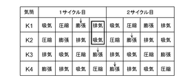
- FIG. 7 shows a cycle diagram of the engine E.
- the first cylinder K1, the second cylinder K2, the third cylinder K3, and the fourth cylinder K4 are arranged in order from the output sprocket 1S side of the crankshaft 1, the first cylinder K1, the third cylinder K3, A case is assumed in which ignition is performed in the order of the fourth cylinder K4 and the second cylinder K2.
- the cylinder K that is first burned (first explosion) after cranking after the engine E is started is not constant, but in this embodiment, it is assumed that the first cylinder K1 burns for the first time immediately after cranking. The following will be described (see the arrow in FIG. 7).
- the intake valve Va is opened during the intake stroke by the cranking, and then the intake valve Va is opened during the compression stroke. Blocks and compresses fresh air.
- fuel is injected into the combustion chamber Ka by the injector 9, ignition is performed by the spark plug 10, and the fuel is combusted in the expansion stroke (combustion stroke) (first explosion).
- the exhaust valve Vb is opened immediately before the bottom dead center BDC in the expansion stroke, and the combustion gas is discharged into the exhaust passage 12 in the exhaust stroke.
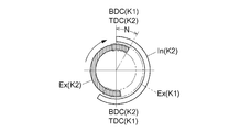
- the solid line shown in FIG. 8 indicates that the intake valve Va of the second cylinder K2 is opened based on the operation of the piston 4 in a state where the relative rotational phase of the valve opening / closing timing control device B on the exhaust side is held at the intermediate lock phase LS.
- An intake region In and an exhaust region Ex where the exhaust valve Vb of the second cylinder K2 is opened are shown.
- the time advances in the clockwise direction indicated by the arrow, and the operation is performed as follows with the opening / closing timing by the valve opening / closing timing control device A on the intake side fixed.
- the piston 4 of the second cylinder K2 reaches the top dead center TDC when the relative rotation phase of the valve opening / closing timing control device B on the exhaust side is held at the intermediate lock phase LS, and the intake valve An overlap region N is formed in which the exhaust region Ex where the exhaust valve Vb opens at the timing when Va opens and the intake region In where the intake valve Va opens overlap. That is, the exhaust valve Vb continues to open at the timing when the intake valve Va of the second cylinder K2 opens.
- the relative rotation phase of the intake-side valve opening / closing timing control device A is also maintained at the intermediate lock phase. However, if the phase is such that the overlap region N can be formed after the top dead center TDC, it is the latest. It may be an angular phase or a most advanced angle phase, and is not particularly limited.
- the combustion gas burned in the combustion chamber Ka of the second cylinder K2 is discharged from the open exhaust valve Vb to the exhaust passage 12 as the piston 4 rises. Then, when the piston 4 of the second cylinder K2 reaches the top dead center TDC, the intake valve Va is opened, and air is sucked into the combustion chamber Ka through the intake valve Va as the piston 4 descends. Become. At this time, since the overlap region N is formed, a part of the combustion gas in the exhaust passage 12 at the time of suction can be sucked into the combustion chamber Ka via the exhaust valve Vb (internal EGR). .
- the combustion gas is introduced from the first cylinder K1 in the exhaust stroke to the combustion chamber Ka of the second cylinder K2 in the intake stroke in the first cycle.
- the bypass passage 18 connecting the exhaust passage 12 of the first cylinder K1 and the exhaust passage 12 of the second cylinder K2 is provided, and the electromagnetic valve 28 provided in the bypass passage 18 is provided.
- the solenoid valve controller 51 opens the valve (see FIG. 5).
- the combustion gas of the first cylinder K1 is introduced into the combustion chamber Ka of the second cylinder K2 into which only fresh air has been introduced via the exhaust passage 12 of the second cylinder K2.
- the unburned HC discharged from the first cylinder K1 is recombusted in the combustion chamber Ka of the second cylinder K2 at the time of the first explosion when the combustion discharge amount is large and a large amount of unburned HC is discharged. Fuel HC emissions can be reduced.
- the overlap region N of the second cylinder K2 is located in the early stage of the exhaust stroke (exhaust region Ex (K1)) of the first cylinder K1. Since the early stage of the exhaust stroke is the initial stage when the exhaust valve Vb is opened, the exhaust pressure in the exhaust passage 12 of the first cylinder K1 is high (see FIG. 10). On the other hand, in the second cylinder K2, combustion has not yet started, and since the time has elapsed since the exhaust valve Vb was opened, the exhaust pressure in the exhaust passage 12 of the second cylinder K2 is relatively low. Therefore, most of the combustion gas in the first cylinder K1 can be introduced into the combustion chamber Ka of the second cylinder K2. Therefore, the amount of unburned HC discharged can be reliably reduced.
- the phase control unit 52 creates the overlap region N by setting the relative rotational phase of the valve opening / closing timing control device B on the exhaust side to the retard side, and the electromagnetic valve control unit 51 causes the electromagnetic valve 28 to Open the valve.
- the solenoid valve 28 is closed by the solenoid valve controller 51. Note that the solenoid valve 28 is preferably closed during cranking until the first combustion is performed in the combustion chamber Ka of the first cylinder K1. As a result, exhaust interference is suppressed in each cylinder K, so that the pumping loss of each cylinder K can be reduced.
- the engine E of the present embodiment supplies fuel to the combustion chamber Ka in such a form that fuel is directly injected from the injector 9, so that the inner wall of the cylinder K that constitutes the combustion chamber Ka, particularly when starting at an environmental temperature below the set value. Part of the fuel tends to adhere to the surface.
- the adhering fuel is hardly vaporized and remains on the inner wall of the cylinder even after combustion by ignition, and a part of the unburned HC (unburned hydrocarbons together with the combustion gas) ) Will be discharged.
- the configuration is such that the combustion gas of the first cylinder K1 is introduced into the combustion chamber Ka of the second cylinder K2 as in the present embodiment, the temperature of the combustion chamber Ka of the second cylinder K2 increases, so that the injection from the injector 9 The vaporized fuel is easily vaporized, and the inconvenience that the fuel adheres to the inner wall of the cylinder K can be suppressed.
- the amount of combustion injected to the combustion chamber Ka by the injector 9 may be reduced in consideration of the amount of unburned HC introduced. As a result, the unburned HC discharged from the second cylinder K2 can be further reduced.
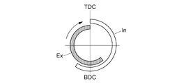
- the phase control unit 52 performs control that does not create the overlap region N. Specifically, the relative rotation phase of the valve opening / closing timing control device B on the exhaust side is controlled to the advance side, and the opening timing (exhaust region Ex) of the exhaust valve Vb of each cylinder K is advanced as shown in FIG. . Accordingly, when idling with a small amount of fresh air introduced into the cylinder K, the internal EGR is not introduced into the combustion chamber Ka, so that combustion stability can be ensured. At this time, the solenoid valve 28 of the bypass passage 18 is preferably closed at the same time.
- the phase control unit 52 creates an overlap region N by setting the relative rotation phase of the valve opening / closing timing control device B on the exhaust side to the retard side, and the electromagnetic valve control unit 51 Thus, the electromagnetic valve 28 is opened.
- the charging efficiency is calculated based on the intake air temperature measured by the intake air temperature sensor 53, the intake air pressure measured by the intake air pressure sensor 54, and the intake air amount measured by the air flow meter 55.
- the flow rate of the internal EGR returned to the combustion chamber Ka of the other cylinder K is increased, so that the internal EGR can be reliably introduced into the combustion chamber Ka. Therefore, discharge of unburned HC can be suppressed.
- the internal EGR is introduced in the high load region, knocking can be suppressed, the ignition timing can be advanced, and the thermal efficiency (fuel consumption and torque) can be improved.
- the electromagnetic valve 28 provided in the bypass passage 18 may be omitted. In this case, when it is not necessary to introduce the combustion gas from any cylinder K to the other cylinder K by the bypass passage 18, if the phase control unit 52 performs control that does not create the overlap region N, the electromagnetic valve 28 and Similar functions can be secured.
- the check valve 19 in the bypass passage 18 may be omitted and only the electromagnetic valve 28 may be configured.
- the electromagnetic valve 28 is closed at a timing when the exhaust gas existing in the exhaust passage 12 of the other cylinder K in the exhaust stroke from the rotation angle of the engine E flows into the combustion chamber Ka of the other cylinder K in the expansion stroke. do it. Thereby, the function equivalent to the check valve 19 can be ensured in the electromagnetic valve 28.
- the relative rotation phase of the valve timing control device B on the exhaust side may be set not in the intermediate lock phase LS but in the most retarded phase or a region close to the most retarded phase. That is, the state in which the open state of the exhaust valve Vb is maintained at the timing when the intake valve Va is opened (the relationship in which the overlap region N is formed) is maintained, and the relative rotational phase is the most retarded than the intermediate phase. It is set in a region close to the phase. By setting in this way, after the engine E is started, a region where the relative rotation phase of the valve opening / closing timing control device B on the exhaust side can be displaced in the advance direction Sa can be expanded.
- the intake-side valve opening / closing timing control device A By controlling the intake-side valve opening / closing timing control device A, the time during which the exhaust valve Vb remains open (the time during which the overlap region N is formed) is adjusted when the intake valve Va is opened. You may comprise so that it can. By configuring in this way, the overlap region N can be set to a value adapted to the state of the engine E.
- the engine E (internal combustion engine) may be configured by including the injector 9 at a position where fuel is injected from the intake path side into the combustion chamber Ka at the timing when the intake valve Va is opened. Even if the injector 9 is provided at such a position, the control device for the internal combustion engine enables reduction of unburned HC when the engine E is started.
- the present invention can be used for an internal combustion engine equipped with a valve opening / closing timing control device for setting the opening / closing timing of an exhaust valve.
Landscapes
- Engineering & Computer Science (AREA)
- Mechanical Engineering (AREA)
- General Engineering & Computer Science (AREA)
- Chemical & Material Sciences (AREA)
- Combustion & Propulsion (AREA)
- Materials Engineering (AREA)
- Health & Medical Sciences (AREA)
- Chemical Kinetics & Catalysis (AREA)
- Toxicology (AREA)
- Output Control And Ontrol Of Special Type Engine (AREA)
- Exhaust Silencers (AREA)
- Exhaust-Gas Circulating Devices (AREA)
Abstract
未燃HCの排出を一層抑制することができる内燃機関の制御装置を提供する。内燃機関の制御装置は、内燃機関と、弁開閉時期制御装置と、を備える。内燃機関は、燃焼室を含む複数の気筒と、燃焼室と吸気通路との間に設けられた吸気弁と、燃焼室と排気通路との間に設けられた排気弁と、を有する。弁開閉時期制御装置は、駆動側回転体および従動側回転体の相対回転位相を設定する位相調節機構を有する。位相調節機構は、所定の期間において、上死点位置よりも後に排気弁が閉弁するように相対回転位相を設定することにより、吸気弁の開放時期と排気弁の開放時期とをオーバーラップさせ、排気行程にある何れかの気筒の排気通路と、排気行程と同時期に吸気行程にある他の気筒の排気通路と、を接続するバイパス通路が設けられている。
Description
本発明は、内燃機関の制御装置に関し、詳しくは、未燃HCの排出を抑制する技術に関する。
エンジン始動時には、気筒における初回の燃焼(初爆)を確実に実行するために燃焼室に導入される燃料噴射量が多く、不完全燃焼による未燃HC(炭化水素)が増大し易い。また、エンジン始動時には、未燃HCを浄化する触媒が温まっておらず活性化されていないため、未燃HCが外部に排出され易い。
特許文献1には、各気筒の初爆から次回の燃焼までの間に吸気弁の開放時期と排気弁の開放時期とをオーバーラップさせることにより、2サイクル目(以降、吸気,圧縮,膨張,排気の4行程で「1サイクル」と表現する。)以降に排気通路に存在する未燃HCを含む排気を燃焼室に戻して再燃焼させ、未燃HCの排出量を低減する、所謂、内部EGR(排気再循環)と呼ばれる技術が開示されている。また、排気通路が昇温された後は、排気弁を進角させることにより膨張行程終盤で排気弁を開弁させ、燃焼室に加えて排気通路内でも燃焼を継続させる技術が開示されている。これにより、触媒を早期に活性化させて未燃HCの浄化効率を向上させるものである。
特許文献2には、初爆を含む1サイクル目の各気筒の吸気圧力と、該吸気圧力の変化量とに基づいて、2サイクル目以降の燃料噴射量を設定する技術が開示されている。これにより、排気通路や燃焼室に付着した燃料を考慮した燃料噴射量の設定を2サイクル目以降に実行して、不完全燃焼による未燃HCの排出量を減少させるものである。
しかしながら、従来の内燃機関の制御装置は、初爆を含む1サイクル目より後の2サイクル目以降でしか未燃HCの排出量を減少させることができない。つまり、燃料噴射量が多い初爆時に、未燃HCの排出を確実に抑制することができず、改善の余地がある。
そこで、未燃HCの排出を一層抑制することができる内燃機関の制御装置が望まれている。
内燃機関の制御装置の特徴構成は、燃焼室を含む複数の気筒と、前記気筒の内部で上死点位置と下死点位置との間を移動するピストンと、前記ピストンと連結されたクランクシャフトと、夫々の前記気筒の前記燃焼室に接続された吸気通路および排気通路と、夫々の前記気筒の前記燃焼室と前記吸気通路および前記排気通路との接続口に各別に設けられた吸気弁および排気弁と、前記吸気弁および前記排気弁と各別に連結された吸気シャフトおよび排気シャフトと、を有する内燃機関と、前記クランクシャフトと同期回転する駆動側回転体と、前記駆動側回転体の回転軸芯と同軸芯上で前記駆動側回転体と相対回転自在に配置され、前記排気シャフトと一体回転する従動側回転体と、前記駆動側回転体および前記従動側回転体の相対回転位相を設定する位相調節機構と、を有する弁開閉時期制御装置と、を備え、前記位相調節機構は、所定の期間において、前記上死点位置よりも後に前記排気弁が閉弁するように前記相対回転位相を設定することにより、前記吸気弁の開放時期と前記排気弁の開放時期とをオーバーラップさせ、排気行程にある何れかの前記気筒の前記排気通路と、前記排気行程と同時期に吸気行程にある他の前記気筒の前記排気通路と、を接続するバイパス通路が設けられている点にある。
本構成では、ピストンが上死点位置から下死点位置に移動する吸気行程において、排気弁の開放時期と吸気弁の開放時期とをオーバーラップさせている。その結果、排気通路に存在する未燃HCを含む排気を燃焼室に戻して未燃HCを再燃焼させ、未燃HCの排出量を低減することができる。
また、本構成では、排気行程にある何れかの気筒の排気通路と、該排気行程と同時期に吸気行程にある他の気筒の排気通路と、を接続するバイパス通路が設けられている。これにより、何れかの気筒における未燃HCを含む排気が、オーバーラップ期間で排気弁が開放した状態の他の気筒の燃焼室に導入される。その結果、他の気筒の排気通路に存在する未燃HCを含む排気が燃焼室に戻されるだけでなく、何れかの気筒の排気通路に存在する未燃HCを含む排気も他の気筒の燃焼室に導入される。よって、例えば燃料噴射量が多く未燃HCが大量に排出される初爆時において、何れかの気筒から排出された未燃HCが他の気筒の燃焼室に導入されて再燃焼されるので、未燃HCの排出量をさらに低減することができる。
このように、未燃HCの排出をさらに抑制することができる内燃機関の制御装置を提供できた。
他の構成は、前記バイパス通路には、前記何れかの気筒の前記排気通路から前記他の気筒の前記排気通路への排気の流通を許容し、前記他の気筒の前記排気通路から前記何れかの気筒の前記排気通路への排気の流通を遮断する逆止弁が設けられている点にある。
吸気,圧縮,膨張,排気の1サイクル(4行程)を繰り返す内燃機関において、何れかの気筒が排気行程であり、且つ、他の気筒が吸気行程である組合せでは、何れかの気筒が膨張行程時に他の気筒が排気行程となる。そこで、本構成のように、他の気筒の排気通路から何れかの気筒の排気通路への排気の逆流を防止する逆止弁を設ければ、排気行程にある他の気筒の排気通路に存在する排気が、膨張行程にある何れかの気筒の燃焼室に大量に流入して燃焼安定性を低下させるといった不都合を防止することができる。
他の構成は、前記バイパス通路には電磁弁が設けられている点にある。
例えば初爆から所定時間経過した後のアイドリング時においては、気筒に導入される新気量が少ないため、何れかの気筒から排出された未燃HCを他の気筒の燃焼室に導入することで燃焼安定性を低下させることがある。そこで、本構成のようにバイパス通路に電磁弁を設ければ、上記タイミングで電磁弁を閉弁してバイパス通路を連通させないといった制御が可能となる。これにより、未燃HCの排出低減と燃焼安定性とのバランスを考慮した制御を実行することができる。
他の構成は、前記所定の期間は、前記何れかの気筒においてクランキング直後に前記燃焼室で初回の燃焼が実行される前から、前記初回の燃焼が実行された後に開いた前記排気弁が初めて閉塞するまでの期間であり、前記電磁弁は、前記所定の期間中に開弁しており、前記所定の期間が終了したときに閉弁する点にある。
本構成では、何れかの気筒において初回の燃焼が実行される前から電磁弁を開弁しているので、何れかの気筒における排気行程の序盤の高い圧力を持った排気が、オーバーラップ期間で排気弁が開放した状態の他の気筒の燃焼室に導入される。その結果、初爆時の未燃HCが多く含まれる排気を再燃焼させ、未燃HCの排出量を確実に低減することができる。また、本構成では、何れかの気筒において初回の燃焼が実行されてから初めて排気弁が閉弁するタイミングで電磁弁を閉弁するので、初爆を迎える何れかの気筒の排気を他の気筒に導入した後は、気筒間での排気のやり取りを禁止することとなる。その結果、電磁弁を閉弁した後は、各気筒毎における排気弁の開弁時期と吸気弁の開弁時期とのオーバーラップにより内部EGRを導入したり、オーバーラップを無くして新気の取込み量を多くしたりして、未燃HCの排出低減と燃焼安定性とのバランスを考慮した制御を実行することができる。
他の構成は、前記内燃機関の作動中において、前記所定の期間は、前記内燃機関の充填効率が所定値以上で、且つ、前記内燃機関の回転数が所定回転数以下の高負荷低回転状態となっている期間であり、前記電磁弁は、前記所定の期間中のみ開弁する点にある。
高負荷低回転領域では吸気圧力が高いため、気筒の燃焼室に内部EGRを導入し難い。そこで、本構成のように高負荷低回転状態の期間において電磁弁を開弁すれば、何れかの気筒の排気通路における排気行程の序盤の高い圧力を持った排気が、オーバーラップ期間で排気弁が開弁した他の気筒の排気通路に導入される。その結果、他の気筒の燃焼室に戻される内部EGRの流速が高まるので、内部EGRを燃焼室に確実に導入することが可能となる。よって、未燃HCの排出を抑制することができる。
以下、本発明の実施形態を図面に基づいて説明する。ただし、以下の実施形態に限定されることなく、その要旨を逸脱しない範囲内で種々の変形が可能である。
図1および図2に示すように、エンジンE(内燃機関の一例)と、エンジンEの吸気弁Vaの開閉時期を設定する吸気側の弁開閉時期制御装置Aと、エンジンEの排気弁Vbの開閉時期を設定する排気側の弁開閉時期制御装置Bと、エンジンEとを制御するエンジン制御ユニット(ECU)50とを備えて内燃機関の制御装置が構成されている。
〔内燃機関〕
図1に示すエンジンEは、乗用車等の車両に備えられるものである。エンジンEは、4つの気筒K(シリンダ)と、ピストン4と、クランクシャフト1と、吸気通路11と、排気通路12と、吸気弁Vaと、排気弁Vbと、吸気シャフト7(吸気側カムシャフト)と、排気シャフト8(排気側カムシャフト)とを備えている。
図1に示すエンジンEは、乗用車等の車両に備えられるものである。エンジンEは、4つの気筒K(シリンダ)と、ピストン4と、クランクシャフト1と、吸気通路11と、排気通路12と、吸気弁Vaと、排気弁Vbと、吸気シャフト7(吸気側カムシャフト)と、排気シャフト8(排気側カムシャフト)とを備えている。
気筒Kは、シリンダブロック2の内周壁とシリンダヘッド3の底壁とで構成されている。気筒Kは、ピストン4を摺動自在に収容しており、上死点位置にあるピストン4の冠面とシリンダブロック2の内周壁とシリンダヘッド3の底壁とで囲まれた空間として燃焼室Kaを有している。シリンダヘッド3には、燃焼室Kaに燃料を噴射するインジェクタ9と点火プラグ10とが備えられている。
ピストン4は、気筒Kの内部で上死点位置と下死点位置との間を移動する。クランクシャフト1は、シリンダブロック2に支持されており、コネクティングロッド5によりピストン4と連結されている。
吸気通路11は、シリンダヘッド3に連結されたインテークマニホールド11aのサージタンク(不図示)から吸気弁Vaまでの流路であり、気筒Kの燃焼室Kaに接続されている。吸気弁Vaは、シリンダヘッド3に支持されており、燃焼室Kaと吸気通路11との接続口(吸気ポート)を開閉する弁体である。インテークマニホールド11aには、吸気温センサ53、吸気圧センサ54およびエアフロメータ55が設けられている。
図1および図5に示すように、排気通路12は、シリンダヘッド3に連結されたエキゾーストマニホールド12aの合流部Tから排気弁Vbまでの流路であり、気筒Kの燃焼室Kaに接続されている。排気弁Vbは、シリンダヘッド3に支持されており、燃焼室Kaと排気通路12との接続口(排気ポート)を開閉する弁体である。なお、本実施形態では、各気筒Kに接続される4つの排気通路12を1つの合流部Tで合流させているが、何れか2つの気筒Kに接続される排気通路12の組合せを合流部Tで合流させた後に2組の排気通路12を再合流させる構成にしても良い。
排気通路12が合流する合流部Tの下流側には、燃焼ガス(排気、以下「燃焼ガス」と言う。)を浄化する触媒コンバータ13を備えている。エンジンEの始動時には触媒コンバータ13の内部温度が低いため、未燃HCが触媒コンバータ13で処理されずに排出されるおそれがある。
そこで、本実施形態では、2つの排気通路12どうしを接続するバイパス通路18を設けている。本実施形態のエンジンEは、4つの気筒Kで構成されているので、バイパス通路18が4つ設けられている。これらバイパス通路18は、排気行程にある何れかの気筒Kの排気通路12と、排気行程と同時期に吸気行程にある他の気筒Kの排気通路12とを接続するものである。具体的には、1番気筒K1と2番気筒K2、1番気筒K1と3番気筒K3、2番気筒K2と4番気筒K4、および3番気筒K3と4番気筒K4の各排気通路12を接続する4つのバイパス通路18が設けられている。これにより、何れかの気筒Kの排気行程で排出された未燃HCを含む燃焼ガスを、他の気筒Kの燃焼室Ka内に導入して、未燃HCを再燃焼させる。
4つのバイパス通路18には、何れかの気筒Kの排気通路12から他の気筒Kの排気通路12への燃焼ガスの流通を許容し、他の気筒Kの排気通路12から何れかの気筒Kの排気通路12への燃焼ガスの流通を遮断する逆止弁19が夫々設けられている。具体的には、逆止弁19は、排気行程にある1番気筒K1から同時期に吸気行程にある2番気筒K2への燃焼ガスの流通を許容し、排気行程にある2番気筒K2から同時期に膨張行程にある1番気筒K1への燃焼ガスの流通を遮断する(図7参照)。同様に、逆止弁19は、2番気筒K2から4番気筒K4への燃焼ガスの流通を許容し、4番気筒K4から2番気筒K2への燃焼ガスの流通を遮断する。また、逆止弁19は、3番気筒K3から1番気筒K1への燃焼ガスの流通を許容し、1番気筒K1から3番気筒K3への燃焼ガスの流通を遮断する。また、逆止弁19は、4番気筒K4から3番気筒K3への燃焼ガスの流通を許容し、3番気筒K3から4番気筒K4への燃焼ガスの流通を遮断する。これによって、排気行程にある他の気筒Kの排気通路12に存在する排気が、膨張行程にある何れか気筒Kの燃焼室Kaに大量に流入して燃焼安定性を低下させるといった不都合を防止することができる。
さらに、4つのバイパス通路18には、逆止弁19よりも燃焼ガスが流通する方向の上流側に、電磁弁28が夫々設けられている。電磁弁28の配置により、逆止弁19の開閉の有無に関係なく、電磁弁28を閉弁することにより燃焼ガスの流通を遮断することが可能となる。その結果、逆止弁19が開閉を繰り返すことないので、逆止弁19の長寿命化を図ることができる。なお、電磁弁28を、バイパス通路18の経路上において逆止弁19よりも燃焼ガスが流通する方向の下流側に設けても良い。
図1に示すように、吸気シャフト7は、シリンダヘッド3に支持されており、吸気弁Vaと連結されている。排気シャフト8は、シリンダヘッド3に支持されており、排気弁Vbと連結されている。吸気シャフト7が回転駆動されることで吸気弁Vaの開閉が実行され、排気シャフト8が回転駆動されることで排気弁Vbの開閉が実行される。
このエンジンEでは、クランクシャフト1に駆動回転力を伝えるスタータモータ15を備え、クランクシャフト1の近傍位置には回転角と回転数とを検知するシャフトセンサ16を備えている。また、後述する排気側の弁開閉時期制御装置Bの近傍には外部ロータ20と内部ロータ30との相対回転位相を検知する位相センサ17を備えている。
〔弁開閉時期制御装置〕
吸気側の弁開閉時期制御装置Aと排気側の弁開閉時期制御装置Bとは同様の構成であるため、以下では、排気側の弁開閉時期制御装置Bの構成を中心として説明する。なお、弁開閉時期制御装置Aおよび弁開閉時期制御装置Bを油圧式の弁開閉時期制御装置として説明するが、弁開閉時期制御装置Aおよび弁開閉時期制御装置Bの少なくとも何れか一方を、電動式の弁開閉時期制御装置として構成しても良い。
吸気側の弁開閉時期制御装置Aと排気側の弁開閉時期制御装置Bとは同様の構成であるため、以下では、排気側の弁開閉時期制御装置Bの構成を中心として説明する。なお、弁開閉時期制御装置Aおよび弁開閉時期制御装置Bを油圧式の弁開閉時期制御装置として説明するが、弁開閉時期制御装置Aおよび弁開閉時期制御装置Bの少なくとも何れか一方を、電動式の弁開閉時期制御装置として構成しても良い。
排気側の弁開閉時期制御装置Bは、外部ロータ20と内部ロータ30との相対回転位相(以下、相対回転位相と称する)の変更により排気弁Vbの開閉タイミング(開閉時期)を制御するように構成されている。
図1~図4に示すように、排気側の弁開閉時期制御装置Bは、排気シャフト8の回転軸芯Xを中心に回転する外部ロータ20(駆動側回転体の一例)と、排気シャフト8に対して連結ボルト33により連結された内部ロータ30(従動側回転体の一例)と、外部ロータ20と内部ロータ30とに亘って設けられたロック機構Lと、弁ユニットVU(位相調節機構の一例)とを備えている。詳細は後述するが、ロック機構Lは、ロック部材25と、ロックスプリング26と、ロック凹部LDと、規制凹部Dsとで構成されている。
外部ロータ20は、円筒状となるロータ本体21と、回転軸芯Xに沿う方向でロータ本体21の一方の端部に配置されるリヤブロック22と、回転軸芯Xに沿う方向でロータ本体21の他方の端部に配置されるフロントプレート23とを備え、これらを複数の締結ボルト24により締結して構成されている。
リヤブロック22の外周には、クランクシャフト1から回転力が伝達される駆動スプロケット22Sが形成されている。同様に吸気側の弁開閉時期制御装置Aの外周側にもスプロケット7Sが設けられている。排気側の弁開閉時期制御装置Bの駆動スプロケット22Sと、吸気側の弁開閉時期制御装置Aの外周のスプロケット7Sと、クランクシャフト1の出力スプロケット1Sとに亘って、タイミングチェーン6が巻回されている(図1参照)。これによって、外部ロータ20がクランクシャフト1と同期回転するように構成されている。
排気側の弁開閉時期制御装置Bでは、タイミングチェーン6から伝えられる駆動力により外部ロータ20が駆動回転方向Sの方向に回転する。外部ロータ20に対して内部ロータ30が駆動回転方向Sと同方向へ回転する方向を進角方向Saと称し、この逆方向への回転方向を遅角方向Sbと称する。排気側の弁開閉時期制御装置Bでは、相対回転位相が進角方向Saに変位することにより、排気弁Vbの開放タイミング(開放時期)と閉塞タイミング(閉塞時期)とを早める。これとは逆に回転位相が遅角方向Sbに変位することにより、排気弁Vbの開放タイミング(開放時期)と閉塞タイミング(閉塞時期)とを遅くする。
ロータ本体21には、円筒状の内壁面から回転軸芯Xに近接する方向(径方向内側)に突出する複数の突出部21Tが一体的に形成されている。複数の突出部21Tのうち、1つの突出部21Tに対して径方向外側に沿うガイド溝が形成され、このガイド溝にプレート状のロック部材25が出退自在に挿入されている。ロータ本体21の内部には、ロック部材25を回転軸芯Xに接近する方向に付勢する付勢手段としてのロックスプリング26が配置されている。
内部ロータ30は、外部ロータ20の回転軸芯Xと同軸芯上に配置され、外部ロータ20に内包された状態で相対回転自在に支持されている。内部ロータ30の外周面には、ロック部材25が係合するロック凹部LDが形成されている。ロック凹部LDに連なる領域に対して、ロック部材25の相対回転位相の遅角側(遅角方向Sb)への変位を規制する規制凹部Dsが、ロック凹部LDよりも浅い長溝状に形成されている(図3参照)。
内部ロータ30を外部ロータ20に内包することで複数の突出部21Tの間に流体圧室Cが区画形成される。さらに、この流体圧室Cをベーン31が仕切る形態となり進角室Caと遅角室Cbとが形成されている。また、内部ロータ30には、進角室Caに連通する進角流路34と、遅角室Cbに連通する遅角流路35と、ロック凹部LDに対してロック解除方向に作動油を供給するロック解除流路36とが形成されている。
また、外部ロータ20のリヤブロック22と内部ロータ30とに亘って、トーションスプリング27が備えられている。トーションスプリング27は、例えば、相対回転位相が最遅角位相にある状態でも、排気シャフト8から作用するカム平均トルクに対抗して相対回転位相が少なくとも中間ロック位相LSに達するまで内部ロータ30に付勢力を作用させるように構成されている。ここで、中間ロック位相LSとは、最進角位相と最遅角位相とを除く、最進角位相と最遅角位相との間の位相のことである。
ロック機構Lは、外部ロータ20に対し、回転軸芯Xに近接又は離間する方向にシフト自在に支持されたロック部材25と、ロック部材25を突出方向に付勢する付勢部材としてのロックスプリング26と、内部ロータ30に形成されたロック凹部LDおよび規制凹部Dsとで構成されている。ロック部材25の形状はプレート状であるが、プレート状に限るものではなく、例えば、ロッド状であっても良い。また、ロック部材25を内部ロータ30に支持し、ロック凹部を外部ロータ20に形成するようにロック機構Lを構成しても良い。
本実施形態における排気側の弁開閉時期制御装置Bでは、相対回転位相が中間ロック位相LS(図3参照)にある場合に、ロック部材25がロックスプリング26の付勢力によりロック凹部LDに係入して相対回転位相が中間ロック位相LSに保持される。一方、ロック機構Lのロックが解除されたときには、中間ロック位相LSから進角方向Sa又は遅角方向Sbに相対回転位相が変位する。図4は、相対回転位相が最進角位相に変位した弁開閉時期制御装置Bを示す。
規制凹部Dsは、ロック部材25が係合することにより相対回転位相の変動幅を小さくする。つまり、ロック部材25が規制凹部Dsに係合した場合には、この規制凹部Dsが形成された領域の間においてのみ相対回転位相の変位が許容される。これにより、ロック部材25のロック凹部LDに係合する状態への移行を容易にする。
図2に示すように、位相調節機構としての弁ユニットVUは、ユニットケースに対して位相制御弁41とロック制御弁42とを収容した構造を有しており、このユニットケースに一体的に形成した流路形成軸部43を内部ロータ30の内周面30Sに挿入する形態で備えられている。この流路形成軸部43の外周面には、位相制御弁41のポートと連通する溝状部と、ロック制御弁42のポートと連通する溝状部とが形成され、これらの溝状部を分離するように流路形成軸部43の外周と、内部ロータ30の内周面30Sとの間には複数のリング状のシール44が備えられている。
位相制御弁41は、進角流路34と遅角流路35との一方を選択して作動油を供給し、他方から排油を行うことにより、相対回転位相を進角方向Sa又は遅角方向Sbに変位させる作動を実現する。また、ロック制御弁42は、中間ロック位相LSにある状態でロック解除流路36に作動油を供給することにより、一対のロック部材25をロック解除方向に作動させてロック解除を実現する。
エンジンEには、オイルパンのオイルを作動油として供給するようにエンジンEで駆動される油圧ポンプPを備えている。この油圧ポンプPからの作動油が弁ユニットVUに供給されるように流路が構成されている。なお、弁ユニットVUでは、位相制御弁41とロック制御弁42とを示しているが、ロック機構Lのロック解除を行えるように位相制御弁41を構成することにより、ロック制御弁42を備えずに弁ユニットVUを構成しても良い。
〔エンジン制御ユニット〕
エンジン制御ユニット50は、吸気側の弁開閉時期制御装置Aの相対回転位相制御と、排気側の弁開閉時期制御装置Bの相対回転位相制御と、ロック機構Lのロック制御とを行うものである(図1、図2参照)。これら制御のうち、本実施形態は、排気側の弁開閉時期制御装置Bによる排気弁Vbの開閉時期の調節を特徴とする。そこで、以下では、排気側の弁開閉時期制御装置Bの相対回転位相制御とロック機構Lのロック制御とを中心に説明する。
エンジン制御ユニット50は、吸気側の弁開閉時期制御装置Aの相対回転位相制御と、排気側の弁開閉時期制御装置Bの相対回転位相制御と、ロック機構Lのロック制御とを行うものである(図1、図2参照)。これら制御のうち、本実施形態は、排気側の弁開閉時期制御装置Bによる排気弁Vbの開閉時期の調節を特徴とする。そこで、以下では、排気側の弁開閉時期制御装置Bの相対回転位相制御とロック機構Lのロック制御とを中心に説明する。
エンジン制御ユニット50は、電磁弁制御部51と位相制御部52とを備えている。エンジン制御ユニット50は、図1に示すように、マイクロプロセッサやDSP等を用い、ソフトウエアにより制御を実現するものであり、電磁弁制御部51と位相制御部52とはソフトウエアで構成されている。なお、これらは、ハードウエアで構成されるものでも良く、ソフトウエアとハードウエアとの組み合わせにより構成されるものであっても良い。
電磁弁制御部51は、バイパス通路18に設けられた4つの電磁弁28の開閉を制御する。位相制御部52は、弁ユニットVUを操作して排気側の弁開閉時期制御装置Bの相対回転位相とロック機構Lとを制御する。
エンジン制御ユニット50には、シャフトセンサ16,位相センサ17,吸気温センサ53,および吸気圧センサ54からの信号が入力される。また、エンジン制御ユニット50は、インジェクタ9,点火プラグ10,スタータモータ15,および弁ユニットVUに制御信号を出力する。
電磁弁制御部51は、シャフトセンサ16から得られるエンジンEの回転角および回転数や、吸気温センサ53で計測された吸気温度、吸気圧センサ54で計測された吸気圧力およびエアフロメータ55で計測された吸気量から算出されるエンジン負荷(充填効率等)に基づいて、電磁弁28の開閉を制御する。
位相制御部52は、シャフトセンサ16から得られるエンジンEの回転角および回転数や、吸気温センサ53で計測された吸気温度、吸気圧センサ54で計測された吸気圧力およびエアフロメータ55で計測された吸気量から算出されるエンジン負荷(充填効率等)に基づき、位相センサ17から相対回転位相をフィードバックする状態で弁ユニットVUを制御して排気側の弁開閉時期制御装置Bの相対回転位相をエンジンEの状態等に適応する位相に設定する。なお、エンジン負荷は、充填効率に限定されず、例えばスロットルバルブの開度やクランクシャフト1に作用するトルクに基づき算出しても良い。
本実施形態では、吸気,圧縮,膨張,排気の4行程を1サイクルとして定義し、図6には、後述するオーバーラップ領域Nが形成された1サイクルの概念図が示される。図6(a)は、圧縮行程を経てピストン4が上死点TDCに達したタイミングを示す。図6(a)のタイミングにおいて、ピストン4の位置が上死点TDCと一致しなくても良い。図6(a)のタイミングで、インジェクタ9により燃焼室Kaに燃料を噴射し、点火プラグ10で点火が行われ膨張行程(燃焼行程)に移行する。
図6(b)は膨張行程に移行したタイミングを示す。図6(b)に示すように、この膨張行程では、吸気弁Vaと排気弁Vbとが閉じ状態にある。この後、ピストン4が下死点BDCに達する直前に排気弁Vbが開放され、図6(c)に示すタイミング(排気行程)で排気弁Vbの開放状態が継続される。この後に、図6(d)に示すタイミングでピストン4が上死点TDCに達し、図6(e)に示すタイミング(吸気行程に移行したタイミング)で吸気弁Vaが開放されると共に、排気弁Vbの開放状態が継続されている。その後、図6(f)に示すタイミング(吸気行程の途中)で排気弁Vbが閉塞される。
図7には、エンジンEのサイクル図が示されている。本実施形態では、クランクシャフト1の出力スプロケット1Sの側から並び順に1番気筒K1,2番気筒K2,3番気筒K3,4番気筒K4とした場合、1番気筒K1,3番気筒K3,4番気筒K4,2番気筒K2の順番で点火するケースを想定している。なお、エンジンEの始動後、クランキングを行って最初に燃焼(初爆)する気筒Kは一定ではないが、本実施形態ではクランキング直後に1番気筒K1で初めて燃焼する場合と仮定して、以下を説明する(図7の矢印参照)。
スタータモータ15のクランキング直後に燃焼室Kaで初回の燃焼が実行される1番気筒K1では、クランキングにより、吸気行程で吸気弁Vaを開放して吸気した後、圧縮行程で吸気弁Vaを閉塞して新気を圧縮する。そして、インジェクタ9により燃焼室Kaに燃料を噴射し、点火プラグ10で点火が行われ、膨張行程(燃焼行程)で燃料を燃焼させる(初爆)。次いで、膨張行程における下死点BDCの直前に排気弁Vbを開放して、排気行程で排気通路12に燃焼ガスを排出する。
図8に示す実線は、排気側の弁開閉時期制御装置Bの相対回転位相を中間ロック位相LSに保持した状態において、ピストン4の作動を基準にして2番気筒K2の吸気弁Vaが開放する吸気領域Inと、2番気筒K2の排気弁Vbが開放する排気領域Exとを示している。図8では、矢印で示す時計回り方向に時間が進むものであり、吸気側の弁開閉時期制御装置Aによる開閉タイミングが固定された状態で以下のように作動が行われる。
エンジンEの始動時において、排気側の弁開閉時期制御装置Bの相対回転位相が中間ロック位相LSに保持されている状態では、2番気筒K2のピストン4が上死点TDCに達して吸気弁Vaが開放するタイミングで排気弁Vbが開放する排気領域Exと、吸気弁Vaが開放する吸気領域Inとが重複するオーバーラップ領域Nが形成される。つまり、2番気筒K2の吸気弁Vaが開放するタイミングで排気弁Vbが開放を継続する。なお、本実施形態では、吸気側の弁開閉時期制御装置Aの相対回転位相も中間ロック位相で保持されているが、上死点TDC後にオーバーラップ領域Nを形成できる位相であれば、最遅角位相や最進角位相であっても良く、特に限定されない。
上述したように2番気筒K2の燃焼室Kaで燃焼した燃焼ガスは、ピストン4の上昇に伴い開放状態の排気弁Vbから排気通路12に排出される。そして、2番気筒K2のピストン4が上死点TDCに達したタイミングで吸気弁Vaを開放し、ピストン4が下降するに伴い吸気弁Vaを介して空気が燃焼室Kaに吸引されることになる。このとき、オーバーラップ領域Nが形成されることにより、この吸引時に排気通路12にある燃焼ガスの一部を、排気弁Vbを介して燃焼室Kaに吸引することが可能となる(内部EGR)。
ところで、エンジンEの始動後には、気筒Kにおける初回の燃焼(初爆)を確実に実行する必要があるため、燃焼室Kaに導入される燃料噴射量が多く、不完全燃焼による未燃HCが増大し易い。また、エンジンEの始動直後には、未燃HCを浄化する触媒コンバータ13が温まっておらず、未だ活性化されていないため、未燃HCが外部に多く排出されてしまう。
そこで、本実施形態では、1サイクル目で排気行程にある1番気筒K1から吸気行程にある2番気筒K2の燃焼室Kaに燃焼ガスを導入することとしている。具体的には、上述したように、1番気筒K1の排気通路12と2番気筒K2の排気通路12とを接続するバイパス通路18を設けており、バイパス通路18に設けられた電磁弁28を電磁弁制御部51により開弁する(図5参照)。これにより、新気しか導入されていない2番気筒K2の燃焼室Kaに、2番気筒K2の排気通路12を経由して1番気筒K1の燃焼ガスが導入される。その結果、燃焼排出量が多く未燃HCが大量に排出される初爆時において、1番気筒K1から排出された未燃HCが2番気筒K2の燃焼室Kaで再燃焼されるので、未燃HCの排出量を低減することができる。
また、図8の二点鎖線で示されるように、2番気筒K2のオーバーラップ領域Nは、1番気筒K1の排気行程(排気領域Ex(K1))の序盤に位置する。この排気行程の序盤は、排気弁Vbが開放された初期であるので、1番気筒K1の排気通路12における排気圧力が高い(図10参照)。一方、2番気筒K2では未だ燃焼が開始されておらず、且つ、排気弁Vbが開放してから時間が経過しているため、2番気筒K2の排気通路12における排気圧力が比較的低い。このため、1番気筒K1の燃焼ガスの多くを2番気筒K2の燃焼室Kaに導入することができる。よって、未燃HCの排出量を確実に低減することができる。
このように、本実施形態では、クランキング直後に1番気筒K1の燃焼室Kaで初回の燃焼が実行される前から、初回の燃焼が実行された後に開いた排気弁Vbが初めて閉塞するまでの期間(所定の期間)において、位相制御部52により排気側の弁開閉時期制御装置Bの相対回転位相を遅角側にしてオーバーラップ領域Nを作り出し、電磁弁制御部51により電磁弁28を開弁する。そして、排気弁Vbが初めて閉塞した後は電磁弁制御部51により電磁弁28を閉弁する。なお、1番気筒K1の燃焼室Kaで初回の燃焼が実行されるまでのクランキング時には、電磁弁28を閉弁していることが好ましい。これによって、各気筒Kにおいて排気干渉が抑制されるので、各気筒Kのポンピングロスを低減することができる。
本実施形態のエンジンEは、燃焼室Kaにインジェクタ9から燃料を直接噴射する形態で供給するため、特に環境温度が設定値未満で始動する際には、燃焼室Kaを構成する気筒Kの内壁に燃料の一部が付着し易い。そして、気筒Kの内壁が低温である場合には、付着した燃料は殆ど気化せず、点火による燃焼の後にもシリンダ内壁に残留し、一部は燃焼ガスと共に未燃HC(未燃焼の炭化水素)として排出されることとなる。
しかしながら、本実施形態のように1番気筒K1の燃焼ガスを2番気筒K2の燃焼室Kaに導入する構成であると、2番気筒K2の燃焼室Kaの温度が高まるので、インジェクタ9から噴射された燃料が気化し易くなり、気筒Kの内壁に燃料が付着するといった不都合を抑制することができる。なお、1番気筒K1から未燃HCが導入される2番気筒K2において、未燃HCの導入量を加味してインジェクタ9により燃焼室Kaに噴射される燃焼噴射量を減少させても良い。これによって、2番気筒K2から排出される未燃HCをさらに減少させることができる。
2サイクル目以降は、各気筒Kで燃焼が開始されているので、オーバーラップ領域Nを作り出すことで内部EGRを作り出すことが可能となる。つまり、バイパス通路18によって何れかの気筒Kから他の気筒Kに燃焼ガスを導入する必要がないので、電磁弁28を閉弁するのが好ましい。なお、2サイクル目以降も、エンジンEの回転数が所定値に到達して完全燃焼した(完爆)と判定されるまでの間は、電磁弁28を開弁した状態に維持して、何れかの気筒Kから他の気筒Kに燃焼ガスを導入しても良い。
一方、エンジンEが低負荷状態であるアイドリング時等には、位相制御部52によってオーバーラップ領域Nを作り出さない制御が実行される。具体的には、排気側の弁開閉時期制御装置Bの相対回転位相を進角側に制御して、図9に示すように各気筒Kの排気弁Vbの開時期(排気領域Ex)を早める。これによって、気筒Kに導入される新気量が少ないアイドリング時において、内部EGRが燃焼室Kaに導入されないので、燃焼安定性を確保することができる。このとき、バイパス通路18の電磁弁28も同時に閉弁することが好ましい。これによって、各気筒Kにおいて排気干渉が抑制されるので、各気筒Kのポンピングロスを低減することができる。なお、環境温度が設定値以上で始動する場合において、1サイクル目にオーバーラップ領域Nを作り出さない制御を実行しても良い。
また、本実施形態では、通常運転に移行した後において、エンジンEの充填効率が所定値(例えば60%)以上で、且つ、エンジンEの回転数が所定回転数(例えば2500rpm)以下の高負荷低回転状態となっているとき(所定の期間)、位相制御部52により排気側の弁開閉時期制御装置Bの相対回転位相を遅角側にしてオーバーラップ領域Nを作り出し、電磁弁制御部51により電磁弁28を開弁することとしている。ここで、充填効率は、吸気温センサ53で計測された吸気温度、吸気圧センサ54で計測された吸気圧力およびエアフロメータ55で計測された吸気量に基づいて算出される。
この高負荷低回転状態では吸気圧力が高いため、気筒Kの燃焼室Kaに内部EGRを導入し難い。このため、本実施形態のように高負荷低回転状態において電磁弁28を開弁すれば、何れかの気筒Kの排気通路12における排気行程の序盤の高い圧力を持った燃焼ガスが、上死点TDCより後のオーバーラップ領域Nで排気弁Vbが開弁した他の気筒Kの排気通路12に導入される。つまり、図10に示すように、他の気筒Kにおける上死点TDCの直後では、実線で示される何れかの気筒Kの高い排気圧力を持った排気行程の序盤が、オーバーラップ領域Nに重なることとなる。
その結果、他の気筒Kの燃焼室Kaに戻される内部EGRの流速が高まるので、内部EGRを燃焼室Kaに確実に導入することが可能となる。よって、未燃HCの排出を抑制することができる。しかも、高負荷領域において内部EGRを導入すれば、ノッキングを抑制することが可能となるので、点火時期を進角させることができ、熱効率(燃費やトルク)を向上させることができる。
〔別実施形態〕
上述した実施形態以外に以下のように構成しても良い。
上述した実施形態以外に以下のように構成しても良い。
(a)バイパス通路18に設けられた電磁弁28を省略しても良い。この場合、バイパス通路18によって何れかの気筒Kから他の気筒Kに燃焼ガスを導入する必要がないとき、位相制御部52によってオーバーラップ領域Nを作り出さない制御を実行すれば、電磁弁28と同様の機能を確保することができる。
(b)バイパス通路18の逆止弁19を省略して、電磁弁28のみで構成しても良い。この場合、エンジンEの回転角度から排気行程にある他の気筒Kの排気通路12に存在する排気が、膨張行程にある他の気筒Kの燃焼室Kaに流入するタイミングで電磁弁28を閉弁すればよい。これにより、電磁弁28において逆止弁19と同等の機能を確保することができる。
(c)排気側の弁開閉時期制御装置Bの相対回転位相を、中間ロック位相LSではなく、最遅角位相又は最遅角位相に近い領域に設定しても良い。つまり、吸気弁Vaが開放するタイミングで、排気弁Vbの開放状態が継続する関係(オーバーラップ領域Nが形成される関係)が維持される状態を、相対回転位相が中間位相よりも最遅角位相に近い領域に設定するのである。このように設定することにより、エンジンEの始動後に、排気側の弁開閉時期制御装置Bの相対回転位相が進角方向Saに変位可能な領域を拡大することができる。
(d)吸気側の弁開閉時期制御装置Aを制御することで、吸気弁Vaが開放する時期に、排気弁Vbの開放状態が継続する時間(オーバーラップ領域Nが形成される時間)を調節できるように構成しても良い。このように構成することにより、オーバーラップ領域NをエンジンEの状態に適応する値に設定することも可能となる。
(e)吸気弁Vaが開放したタイミングで燃焼室Kaに対して吸気経路側から燃料を噴射する位置にインジェクタ9を備えてエンジンE(内燃機関)を構成しても良い。このような位置にインジェクタ9を備えたものであっても、内燃機関の制御装置は、エンジンEを始動する際に未燃HCの低減を可能にする。
本発明は、排気弁の開閉時期を設定する弁開閉時期制御装置を備えた内燃機関に利用することができる。
1 クランクシャフト
4 ピストン
7 吸気シャフト
8 排気シャフト
9 インジェクタ
11 吸気通路
12 排気通路
18 バイパス通路
19 逆止弁
28 電磁弁
20 外部ロータ(駆動側回転体)
30 内部ロータ(従動側回転体)
50 エンジン制御ユニット
B 弁開閉時期制御装置
E エンジン(内燃機関)
K 気筒
Ka 燃焼室
TDC 上死点
BDC 下死点
Va 吸気弁
Vb 排気弁
VU 弁ユニット(位相調節機構)
X 回転軸芯
4 ピストン
7 吸気シャフト
8 排気シャフト
9 インジェクタ
11 吸気通路
12 排気通路
18 バイパス通路
19 逆止弁
28 電磁弁
20 外部ロータ(駆動側回転体)
30 内部ロータ(従動側回転体)
50 エンジン制御ユニット
B 弁開閉時期制御装置
E エンジン(内燃機関)
K 気筒
Ka 燃焼室
TDC 上死点
BDC 下死点
Va 吸気弁
Vb 排気弁
VU 弁ユニット(位相調節機構)
X 回転軸芯
Claims (5)
- 燃焼室を含む複数の気筒と、前記気筒の内部で上死点位置と下死点位置との間を移動するピストンと、前記ピストンと連結されたクランクシャフトと、夫々の前記気筒の前記燃焼室に接続された吸気通路および排気通路と、夫々の前記気筒の前記燃焼室と前記吸気通路および前記排気通路との接続口に各別に設けられた吸気弁および排気弁と、前記吸気弁および前記排気弁と各別に連結された吸気シャフトおよび排気シャフトと、を有する内燃機関と、
前記クランクシャフトと同期回転する駆動側回転体と、前記駆動側回転体の回転軸芯と同軸芯上で前記駆動側回転体と相対回転自在に配置され、前記排気シャフトと一体回転する従動側回転体と、前記駆動側回転体および前記従動側回転体の相対回転位相を設定する位相調節機構と、を有する弁開閉時期制御装置と、を備え、
前記位相調節機構は、所定の期間において、前記上死点位置よりも後に前記排気弁が閉弁するように前記相対回転位相を設定することにより、前記吸気弁の開放時期と前記排気弁の開放時期とをオーバーラップさせ、
排気行程にある何れかの前記気筒の前記排気通路と、前記排気行程と同時期に吸気行程にある他の前記気筒の前記排気通路と、を接続するバイパス通路が設けられている内燃機関の制御装置。 - 前記バイパス通路には、前記何れかの気筒の前記排気通路から前記他の気筒の前記排気通路への排気の流通を許容し、前記他の気筒の前記排気通路から前記何れかの気筒の前記排気通路への排気の流通を遮断する逆止弁が設けられている請求項1に記載の内燃機関の制御装置。
- 前記バイパス通路には電磁弁が設けられている請求項1又は2に記載の内燃機関の制御装置。
- 前記所定の期間は、前記何れかの気筒においてクランキング直後に前記燃焼室で初回の燃焼が実行される前から、前記初回の燃焼が実行された後に開いた前記排気弁が初めて閉塞するまでの期間であり、
前記電磁弁は、前記所定の期間中に開弁しており、前記所定の期間が終了したときに閉弁する請求項3に記載の内燃機関の制御装置。 - 前記内燃機関の作動中において、前記所定の期間は、前記内燃機関の充填効率が所定値以上で、且つ、前記内燃機関の回転数が所定回転数以下の高負荷低回転状態となっている期間であり、
前記電磁弁は、前記所定の期間中のみ開弁する請求項3に記載の内燃機関の制御装置。
Priority Applications (2)
| Application Number | Priority Date | Filing Date | Title |
|---|---|---|---|
| US16/611,907 US11156170B2 (en) | 2017-05-12 | 2018-02-28 | Control device for internal combustion engine |
| CN201880030533.0A CN110612386B (zh) | 2017-05-12 | 2018-02-28 | 内燃机的控制装置 |
Applications Claiming Priority (2)
| Application Number | Priority Date | Filing Date | Title |
|---|---|---|---|
| JP2017095884A JP6869475B2 (ja) | 2017-05-12 | 2017-05-12 | 内燃機関の制御装置 |
| JP2017-095884 | 2017-05-12 |
Publications (1)
| Publication Number | Publication Date |
|---|---|
| WO2018207436A1 true WO2018207436A1 (ja) | 2018-11-15 |
Family
ID=64104617
Family Applications (1)
| Application Number | Title | Priority Date | Filing Date |
|---|---|---|---|
| PCT/JP2018/007442 Ceased WO2018207436A1 (ja) | 2017-05-12 | 2018-02-28 | 内燃機関の制御装置 |
Country Status (4)
| Country | Link |
|---|---|
| US (1) | US11156170B2 (ja) |
| JP (1) | JP6869475B2 (ja) |
| CN (1) | CN110612386B (ja) |
| WO (1) | WO2018207436A1 (ja) |
Families Citing this family (2)
| Publication number | Priority date | Publication date | Assignee | Title |
|---|---|---|---|---|
| CN111765008B (zh) * | 2020-06-18 | 2021-10-15 | 东风汽车集团有限公司 | 内部egr的控制方法,系统及车辆 |
| JP7700735B2 (ja) * | 2022-06-15 | 2025-07-01 | トヨタ自動車株式会社 | 車両の制御装置 |
Citations (3)
| Publication number | Priority date | Publication date | Assignee | Title |
|---|---|---|---|---|
| JP2004124752A (ja) * | 2002-09-30 | 2004-04-22 | Mazda Motor Corp | 過給機付火花点火式エンジンの制御装置 |
| JP2006336579A (ja) * | 2005-06-03 | 2006-12-14 | Toyota Motor Corp | 内燃機関の制御装置 |
| JP2017014941A (ja) * | 2015-06-29 | 2017-01-19 | アイシン精機株式会社 | 弁開閉時期制御装置 |
Family Cites Families (13)
| Publication number | Priority date | Publication date | Assignee | Title |
|---|---|---|---|---|
| JP2000064829A (ja) * | 1998-08-19 | 2000-02-29 | Sango Co Ltd | 内燃機関の排気装置 |
| JP3756034B2 (ja) | 2000-02-04 | 2006-03-15 | 株式会社日立製作所 | 多気筒エンジンのエンジン制御装置 |
| DE10156140B4 (de) * | 2000-11-21 | 2005-12-15 | Mitsubishi Jidosha Kogyo K.K. | Variable Ventilsteuerung |
| JP4591645B2 (ja) | 2001-01-12 | 2010-12-01 | 三菱自動車工業株式会社 | 可変バルブタイミング装置 |
| JP2002180912A (ja) * | 2000-12-08 | 2002-06-26 | Yamaha Motor Co Ltd | エンジンのegr配管構造 |
| JP2009243377A (ja) * | 2008-03-31 | 2009-10-22 | Toyota Motor Corp | 内燃機関 |
| US8042528B2 (en) * | 2009-07-31 | 2011-10-25 | Ford Global Technologies, Llc | Adaptive EGR control for internal combustion engines |
| JP5515977B2 (ja) * | 2010-03-31 | 2014-06-11 | マツダ株式会社 | 多気筒エンジンの排気装置 |
| US8118006B2 (en) * | 2010-04-08 | 2012-02-21 | Ford Global Technologies, Llc | Fuel injector diagnostic for dual fuel engine |
| JP5779331B2 (ja) * | 2010-10-21 | 2015-09-16 | 日立オートモティブシステムズ株式会社 | 筒内噴射式ガソリン機関の制御装置 |
| US9133784B2 (en) * | 2011-02-01 | 2015-09-15 | Ford Global Technologies, Llc | Vehicle having key-based performance mode |
| JP5844225B2 (ja) * | 2012-07-05 | 2016-01-13 | 本田技研工業株式会社 | 内燃機関の内部egr量算出装置 |
| CN105715367B (zh) * | 2016-03-30 | 2018-08-17 | 吉林大学 | 基于可变气道的双燃料点燃式内燃机及控制方法 |
-
2017
- 2017-05-12 JP JP2017095884A patent/JP6869475B2/ja active Active
-
2018
- 2018-02-28 CN CN201880030533.0A patent/CN110612386B/zh active Active
- 2018-02-28 WO PCT/JP2018/007442 patent/WO2018207436A1/ja not_active Ceased
- 2018-02-28 US US16/611,907 patent/US11156170B2/en active Active
Patent Citations (3)
| Publication number | Priority date | Publication date | Assignee | Title |
|---|---|---|---|---|
| JP2004124752A (ja) * | 2002-09-30 | 2004-04-22 | Mazda Motor Corp | 過給機付火花点火式エンジンの制御装置 |
| JP2006336579A (ja) * | 2005-06-03 | 2006-12-14 | Toyota Motor Corp | 内燃機関の制御装置 |
| JP2017014941A (ja) * | 2015-06-29 | 2017-01-19 | アイシン精機株式会社 | 弁開閉時期制御装置 |
Also Published As
| Publication number | Publication date |
|---|---|
| CN110612386A (zh) | 2019-12-24 |
| JP2018193874A (ja) | 2018-12-06 |
| JP6869475B2 (ja) | 2021-05-12 |
| US20210140377A1 (en) | 2021-05-13 |
| CN110612386B (zh) | 2022-03-15 |
| US11156170B2 (en) | 2021-10-26 |
Similar Documents
| Publication | Publication Date | Title |
|---|---|---|
| US7520261B2 (en) | Apparatus for and method of controlling intake operation of an internal combustion engine | |
| JP3699654B2 (ja) | 内燃機関のバルブタイミング制御装置 | |
| JP6510878B2 (ja) | 内燃機関の制御装置 | |
| CN101238278B (zh) | 内燃机 | |
| CN101595290A (zh) | 预混合压缩点火型发动机和控制这种发动机的方法 | |
| JP2011214469A (ja) | 多気筒エンジンの排気装置 | |
| JP3605354B2 (ja) | 内燃機関のバルブタイミング制御装置 | |
| JP3699645B2 (ja) | 内燃機関のバルブタイミング制御装置 | |
| US11156170B2 (en) | Control device for internal combustion engine | |
| CN110382844A (zh) | 发动机的控制装置 | |
| US10619588B2 (en) | Controller for internal combustion engine | |
| CN105026702B (zh) | 内燃机的控制装置 | |
| JP2009293567A (ja) | 内燃機関の動弁制御装置 | |
| JP2020190229A (ja) | 内燃機関の可変動弁システム、及びその制御装置 | |
| JP2014125881A (ja) | 内燃機関 | |
| JP4222072B2 (ja) | エンジンの制御装置 | |
| US9322303B2 (en) | Variable valve timing control unit | |
| JP2008274822A (ja) | 内燃機関の制御装置 | |
| JP5516896B2 (ja) | 可変動弁装置付内燃機関 | |
| JP2017180122A (ja) | 内燃機関の制御装置 | |
| JPH10231742A (ja) | 内燃機関のバルブタイミング制御装置 | |
| JP2012197752A (ja) | エンジンの制御装置 | |
| JP2009221875A (ja) | 内燃機関の制御装置 |
Legal Events
| Date | Code | Title | Description |
|---|---|---|---|
| 121 | Ep: the epo has been informed by wipo that ep was designated in this application |
Ref document number: 18799307 Country of ref document: EP Kind code of ref document: A1 |
|
| NENP | Non-entry into the national phase |
Ref country code: DE |
|
| 122 | Ep: pct application non-entry in european phase |
Ref document number: 18799307 Country of ref document: EP Kind code of ref document: A1 |