WO2018207412A1 - 内燃機関の制御装置 - Google Patents
内燃機関の制御装置 Download PDFInfo
- Publication number
- WO2018207412A1 WO2018207412A1 PCT/JP2018/003105 JP2018003105W WO2018207412A1 WO 2018207412 A1 WO2018207412 A1 WO 2018207412A1 JP 2018003105 W JP2018003105 W JP 2018003105W WO 2018207412 A1 WO2018207412 A1 WO 2018207412A1
- Authority
- WO
- WIPO (PCT)
- Prior art keywords
- compression ratio
- cylinder pressure
- internal combustion
- combustion engine
- cylinder
- Prior art date
- Legal status (The legal status is an assumption and is not a legal conclusion. Google has not performed a legal analysis and makes no representation as to the accuracy of the status listed.)
- Ceased
Links
Images




Classifications
-
- F—MECHANICAL ENGINEERING; LIGHTING; HEATING; WEAPONS; BLASTING
- F02—COMBUSTION ENGINES; HOT-GAS OR COMBUSTION-PRODUCT ENGINE PLANTS
- F02D—CONTROLLING COMBUSTION ENGINES
- F02D35/00—Controlling engines, dependent on conditions exterior or interior to engines, not otherwise provided for
- F02D35/02—Controlling engines, dependent on conditions exterior or interior to engines, not otherwise provided for on interior conditions
- F02D35/023—Controlling engines, dependent on conditions exterior or interior to engines, not otherwise provided for on interior conditions by determining the cylinder pressure
- F02D35/024—Controlling engines, dependent on conditions exterior or interior to engines, not otherwise provided for on interior conditions by determining the cylinder pressure using an estimation
-
- F—MECHANICAL ENGINEERING; LIGHTING; HEATING; WEAPONS; BLASTING
- F02—COMBUSTION ENGINES; HOT-GAS OR COMBUSTION-PRODUCT ENGINE PLANTS
- F02D—CONTROLLING COMBUSTION ENGINES
- F02D35/00—Controlling engines, dependent on conditions exterior or interior to engines, not otherwise provided for
- F02D35/02—Controlling engines, dependent on conditions exterior or interior to engines, not otherwise provided for on interior conditions
- F02D35/023—Controlling engines, dependent on conditions exterior or interior to engines, not otherwise provided for on interior conditions by determining the cylinder pressure
-
- F—MECHANICAL ENGINEERING; LIGHTING; HEATING; WEAPONS; BLASTING
- F02—COMBUSTION ENGINES; HOT-GAS OR COMBUSTION-PRODUCT ENGINE PLANTS
- F02B—INTERNAL-COMBUSTION PISTON ENGINES; COMBUSTION ENGINES IN GENERAL
- F02B75/00—Other engines
- F02B75/04—Engines with variable distances between pistons at top dead-centre positions and cylinder heads
- F02B75/045—Engines with variable distances between pistons at top dead-centre positions and cylinder heads by means of a variable connecting rod length
-
- F—MECHANICAL ENGINEERING; LIGHTING; HEATING; WEAPONS; BLASTING
- F02—COMBUSTION ENGINES; HOT-GAS OR COMBUSTION-PRODUCT ENGINE PLANTS
- F02B—INTERNAL-COMBUSTION PISTON ENGINES; COMBUSTION ENGINES IN GENERAL
- F02B75/00—Other engines
- F02B75/04—Engines with variable distances between pistons at top dead-centre positions and cylinder heads
- F02B75/047—Engines with variable distances between pistons at top dead-centre positions and cylinder heads by means of variable crankshaft position
-
- F—MECHANICAL ENGINEERING; LIGHTING; HEATING; WEAPONS; BLASTING
- F02—COMBUSTION ENGINES; HOT-GAS OR COMBUSTION-PRODUCT ENGINE PLANTS
- F02D—CONTROLLING COMBUSTION ENGINES
- F02D15/00—Varying compression ratio
-
- F—MECHANICAL ENGINEERING; LIGHTING; HEATING; WEAPONS; BLASTING
- F02—COMBUSTION ENGINES; HOT-GAS OR COMBUSTION-PRODUCT ENGINE PLANTS
- F02D—CONTROLLING COMBUSTION ENGINES
- F02D41/00—Electrical control of supply of combustible mixture or its constituents
- F02D41/009—Electrical control of supply of combustible mixture or its constituents using means for generating position or synchronisation signals
-
- F—MECHANICAL ENGINEERING; LIGHTING; HEATING; WEAPONS; BLASTING
- F02—COMBUSTION ENGINES; HOT-GAS OR COMBUSTION-PRODUCT ENGINE PLANTS
- F02P—IGNITION, OTHER THAN COMPRESSION IGNITION, FOR INTERNAL-COMBUSTION ENGINES; TESTING OF IGNITION TIMING IN COMPRESSION-IGNITION ENGINES
- F02P5/00—Advancing or retarding ignition; Control therefor
- F02P5/04—Advancing or retarding ignition; Control therefor automatically, as a function of the working conditions of the engine or vehicle or of the atmospheric conditions
- F02P5/05—Advancing or retarding ignition; Control therefor automatically, as a function of the working conditions of the engine or vehicle or of the atmospheric conditions using mechanical means
- F02P5/10—Advancing or retarding ignition; Control therefor automatically, as a function of the working conditions of the engine or vehicle or of the atmospheric conditions using mechanical means dependent on fluid pressure in engine, e.g. combustion-air pressure
-
- F—MECHANICAL ENGINEERING; LIGHTING; HEATING; WEAPONS; BLASTING
- F02—COMBUSTION ENGINES; HOT-GAS OR COMBUSTION-PRODUCT ENGINE PLANTS
- F02P—IGNITION, OTHER THAN COMPRESSION IGNITION, FOR INTERNAL-COMBUSTION ENGINES; TESTING OF IGNITION TIMING IN COMPRESSION-IGNITION ENGINES
- F02P5/00—Advancing or retarding ignition; Control therefor
- F02P5/04—Advancing or retarding ignition; Control therefor automatically, as a function of the working conditions of the engine or vehicle or of the atmospheric conditions
- F02P5/145—Advancing or retarding ignition; Control therefor automatically, as a function of the working conditions of the engine or vehicle or of the atmospheric conditions using electrical means
- F02P5/15—Digital data processing
- F02P5/152—Digital data processing dependent on pinking
-
- Y—GENERAL TAGGING OF NEW TECHNOLOGICAL DEVELOPMENTS; GENERAL TAGGING OF CROSS-SECTIONAL TECHNOLOGIES SPANNING OVER SEVERAL SECTIONS OF THE IPC; TECHNICAL SUBJECTS COVERED BY FORMER USPC CROSS-REFERENCE ART COLLECTIONS [XRACs] AND DIGESTS
- Y02—TECHNOLOGIES OR APPLICATIONS FOR MITIGATION OR ADAPTATION AGAINST CLIMATE CHANGE
- Y02T—CLIMATE CHANGE MITIGATION TECHNOLOGIES RELATED TO TRANSPORTATION
- Y02T10/00—Road transport of goods or passengers
- Y02T10/10—Internal combustion engine [ICE] based vehicles
- Y02T10/40—Engine management systems
Definitions
- the present invention relates to a control device that estimates the compression ratio of an internal combustion engine, and more particularly to a control device that estimates the compression ratio of an internal combustion engine (variable compression ratio internal combustion engine) having a variable compression ratio mechanism that makes the compression ratio variable. .
- Patent Document 1 includes a piston and a crankshaft of an internal combustion engine connected via a plurality of link members, and a control link that limits the degree of freedom of these link members.
- a variable compression ratio internal combustion engine in which the base end of the control link is slidably connected to the eccentric shaft of the control shaft and the compression ratio changes according to the rotational position of the control shaft.
- a technique is disclosed in which a peak value during a cycle of torque necessary for holding the control shaft in a predetermined compression ratio state is obtained, and an actual compression ratio is estimated from the peak torque.
- the torque peak value is affected by the amount of heat generated by combustion, so that the internal combustion engine It is necessary to limit to the case of engine fuel cut. Further, since the torque peak value is influenced by the intake air amount and the intake air temperature, there is a problem that the intake air amount and the intake air temperature need to be accurately measured or restricted to a certain condition.
- the present invention has been made in view of the above circumstances, and the object of the present invention is not only at the time of fuel cut of the internal combustion engine, but also without being affected by the intake air amount and the intake air temperature, and the compression ratio of the internal combustion engine. It is an object of the present invention to provide a control device for an internal combustion engine that can estimate the above.
- an internal combustion engine control apparatus estimates a compression ratio of an internal combustion engine having cylinders whose intake and exhaust valves open and close in synchronization with rotation of a crankshaft connected to a piston.
- the compression ratio is calculated based on a change in in-cylinder pressure with respect to a crank angle at a timing from when the intake valve is closed until ignition of the air-fuel mixture in the cylinder is started.
- the compression ratio of the internal combustion engine can be estimated not only when the fuel of the internal combustion engine is cut, but also without being affected by the intake air amount and the intake air temperature.
- the figure which shows an example of the in-cylinder volume change rate which normalized the in-cylinder volume differential value with the in-cylinder volume.
- FIG. 11 is a block diagram showing an internal configuration of another example of the control device shown in FIG.
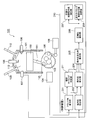
- FIG. 1 shows an internal combustion engine (variable compression ratio internal combustion engine) to which the control device according to the present invention is applied (hereinafter also referred to as an engine or a variable compression ratio engine).
- the intake valve 109 and the exhaust valve 110 provided in the cylinder (cylinder) 101 are opened and closed in synchronization with the rotation of the crankshaft 103, so that the inside of the cylinder 101 (inside the cylinder or in the combustion chamber).
- Air (intake) is taken in.
- Fuel is injected from the injector 106 into the taken-in air, and a mixture of fuel and air is generated in the cylinder 101.
- this air-fuel mixture is ignited (ignited) from the ignition plug 108, the piston 102 is pushed down by the explosion energy, and the pushing force to the piston 102 is transmitted to the crankshaft 103 through the connecting rod 111 and the link mechanism 105.
- the rotation of the crankshaft 103 is, for example, a rotation of a tire through a not-illustrated mission, and is a driving force of an automobile or the like on which the internal combustion engine 100 is mounted.
- crank angle ⁇ of the crankshaft 103 (crank angle ⁇ measured by the crank angle sensor 104) and the volume in the combustion chamber 112 surrounded by the cylinder 101 and the piston 102 (in-cylinder volume).
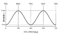
- the relationship with V is as shown in FIG. That is, at the top dead center TDC (Top Dead Center) where the position of the piston 102 is highest, the volume V takes the minimum value Vmin, and at the bottom dead center BDC (Bottom Dead Center) where the position of the piston 102 is lowest, the volume V is Takes the maximum value Vmax.
- the ratio Vmax / Vmin between the minimum value Vmin and the maximum value Vmax is called a compression ratio ⁇ .
- variable compression ratio engine 100 In general, the larger the compression ratio ⁇ , the more efficient the engine 100. However, when the compression ratio ⁇ is increased in a high load region, knocking occurs and the engine 100 is damaged.
- the variable compression ratio engine 100 was developed from such a background. By increasing the compression ratio ⁇ in a low load range and decreasing the compression ratio ⁇ in a high load range, the efficiency of the internal combustion engine 100 is improved. ing.
- the mechanism (variable compression ratio mechanism) that makes the compression ratio ⁇ variable as described above is well known in its configuration, but in the internal combustion engine 100 of the present embodiment, the link mechanism is operated by the compression ratio controller 106.
- the distance between the connecting point 111 of the connecting rod 111 and the link mechanism 105 and the crankshaft 103 changes, and the relationship between the crank angle ⁇ and the volume V changes, so that the compression ratio ⁇ Mechanically variable and controlled.
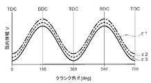
- the relationship between the crank angle ⁇ and the volume V in the variable compression ratio engine 100 is as shown in FIG. 3, for example, and the relationship between the crank angle ⁇ and the volume V for each of the different compression ratios ⁇ 1, ⁇ 2, and ⁇ 3. Is given. Note that the compression ratio ⁇ is not necessarily discrete but may change continuously.
- the compression ratio commanded by the control device 200 (see FIGS. 10 and 13 described later) for controlling the operation state of the internal combustion engine 100,
- the actual compression ratio (actual compression ratio) ⁇ needs to be estimated because the actual compression ratio may differ from the actual compression ratio.
- an in-cylinder pressure sensor 107 is attached to the cylinder 101, and the internal combustion engine 100 has a Measurement of the pressure (in-cylinder pressure) P is under study.
- the in-cylinder pressure P at the time of fuel cut is as shown by a broken line in FIG. 4, and the in-cylinder pressure P at the time of combustion is as shown by a solid line in FIG.
- the intake air amount n and the intake air temperature T in the cylinder 101 are known and the in-cylinder pressure P can be measured, the volume V can be obtained from the equation of state of gas according to the following (Equation 1). Where R is the gas constant of the air / fuel mixture.
- the compression ratio ⁇ can be specified by referring to the relationship between the crank angle ⁇ and the volume V for each compression ratio shown in FIG.
- the above-described method for specifying the compression ratio ⁇ is based on the assumption that the intake air amount n and the intake air temperature T are known, but it is difficult to measure the temperature in the cylinder with the actual engine 100. Further, although an airflow sensor for measuring the intake air amount is attached, it is difficult to estimate how the air that has passed through the airflow sensor enters each cylinder of the engine 100. Therefore, in the present embodiment, a method for estimating the compression ratio ⁇ even if the intake air amount n and the intake air temperature T are not known is proposed.
- the inside of the cylinder 101 is an adiabatic process in which heat does not enter and exit from when the intake valve 109 provided in the cylinder 101 is closed until the air-fuel mixture is ignited and combustion starts.
- the relationship expressed by the following (Equation 2) well known in the field of thermodynamics is established.
- Equation 2 is differentiated by the crank angle ⁇ of the crankshaft 103, the following (Equation 3) is obtained.
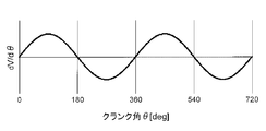
- the relationship between the volume V of the variable compression ratio engine 100 and the crank angle ⁇ can be approximated by translation in the V-axis direction according to the compression ratio ⁇ , so that dV / d ⁇ (in-cylinder volume ( The in-cylinder volume differential value obtained by differentiating the combustion chamber volume V by the crank angle ⁇ does not depend on the compression ratio ⁇ .
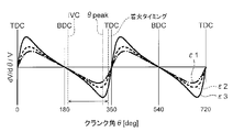
- dV / d ⁇ / V for each compression ratio (cylinder volume change rate obtained by normalizing the in-cylinder volume differential value shown in FIG. 5 with the in-cylinder volume) is as shown in FIG. Shows an extreme value at ⁇ peak about 30 ° before the top dead center TDC, and at this time, the difference due to the compression ratio ⁇ becomes the largest.
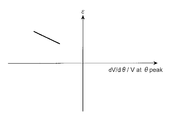
- the relationship between dV / d ⁇ / V and the compression ratio ⁇ at ⁇ peak is as shown in FIG. 7, for example.
- Equation 4 dP / d ⁇ / P (the in-cylinder pressure change rate obtained by normalizing the in-cylinder pressure P obtained by differentiating the in-cylinder pressure P with the crank angle ⁇ ) and the in-cylinder pressure P is proportional to dV / d ⁇ / V.
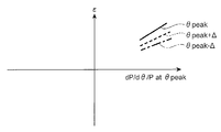
- the relationship shown by the solid line in FIG. 8 is between the compression ratio ⁇ and dP / d ⁇ / P. Therefore, as shown in FIG. 9, the in-cylinder pressure P is measured near ⁇ peak (the upper diagram in FIG. 9), and the in-cylinder pressure P is differentiated by the crank angle ⁇ to calculate the in-cylinder pressure differential value dP / d ⁇ (see FIG. 9).
- the in-cylinder pressure differential value dP / d ⁇ is normalized by the in-cylinder pressure P to obtain the in-cylinder pressure change rate dP / d ⁇ / P (the lower diagram in FIG. 9). Then, the actual compression ratio (actual compression ratio) ⁇ is estimated based on the relationship between the in-cylinder pressure change rate dP / d ⁇ / P and the compression ratio ⁇ obtained in advance as shown in FIG.
- the expression 4 is an expression of only the in-cylinder pressure P, the volume V, and the specific heat ratio ⁇ .
- the specific heat ratio ⁇ is uniquely determined if the gas component is determined. Even if the component ratio of the fuel changes, this specific heat ratio ⁇ is approximately 1.3, so that Equation 4 is considered to hold regardless of the operating conditions.
- dP / d ⁇ / P depends not only on the timing of ⁇ peak, but also before and after it, depending on the compression ratio ⁇ . And change.
- dP / d ⁇ / P and the compression ratio ⁇ is plotted at ⁇ before and after ⁇ peak, for example, it is as shown by a broken line or a dashed line in FIG. It can be seen that the compression ratio (actual compression ratio) ⁇ can be estimated from dP / d ⁇ / P even using this relationship.
- the problem is whether the range of dP / d ⁇ / P before and after ⁇ peak has a correlation with the compression ratio ⁇ , but the range in which Equation 4 holds, that is, the combustion chamber that is the premise for the derivation of Equations 2 to 4
- the control device 200 changes the in-cylinder pressure P with respect to the crank angle ⁇ at the timing from when the intake valve 109 is closed until ignition of the air-fuel mixture in the cylinder 101 starts.
- the compression ratio ⁇ is calculated based on dP / d ⁇ . More specifically, the control device 200 calculates the compression ratio based on the in-cylinder pressure change rate dP / d ⁇ / P obtained by normalizing the change dP / d ⁇ in the in-cylinder pressure P with respect to the crank angle ⁇ . Thereby, the actual compression ratio ⁇ of the internal combustion engine 100 can be estimated.
- FIG. 10 shows an internal configuration of an embodiment of the control device according to the present invention that realizes the above-described compression ratio estimation.
- a control device 200 shown in FIG. 10 basically includes a microcomputer including an input / output port, a RAM, a ROM, a CPU, and the like. Mainly, a crank angle calculation unit 201, an in-cylinder pressure calculation unit 202, An adiabatic change timing determination unit 203, an in-cylinder pressure differentiation unit 204, an in-cylinder pressure change rate calculation unit 205, and a compression ratio calculation unit 206 are provided.
- the crank angle calculation unit 201 acquires a signal from a crank angle sensor 104 provided on the crankshaft 103 and calculates a crank angle ⁇ of the crankshaft 103.
- the in-cylinder pressure calculation unit 202 calculates a pressure (in-cylinder pressure) P in the cylinder 101 by acquiring a signal from an in-cylinder pressure sensor 107 provided in the cylinder 101.
- the crank angle ⁇ calculated by the crank angle calculation unit 201 is a timing at which the inside of the combustion chamber 112 (inside the cylinder) changes adiabatically (that is, after the intake valve 109 is closed) It is determined whether or not the timing until ignition of the air-fuel mixture begins is started).
- in-cylinder pressure differentiation unit 204 three examples corresponding to different in-cylinder pressures P (different compression ratios) calculated by the in-cylinder pressure calculation unit 202 with respect to the crank angle ⁇ calculated by the crank angle calculation unit 201 are shown in the upper part of FIG.
- the cylinder pressure differential value dP / d ⁇ (the result of differentiating the three cylinder pressures P shown in the upper diagram of FIG. 9 is shown in the middle diagram of FIG. 9) is calculated.
- the in-cylinder pressure change rate calculation unit 205 calculates the in-cylinder pressure differential value dP / d ⁇ calculated by the in-cylinder pressure differentiation unit 204 at the timing when the adiabatic change timing determination unit 203 determines that the inside of the combustion chamber 112 is adiabatically changed. Normalized by in-cylinder pressure P and in-cylinder pressure change rate dP / d ⁇ / P (The result of normalizing the three in-cylinder pressure differential values dP / d ⁇ shown in the middle diagram of FIG. 9 is shown in the lower diagram of FIG. 9) Is calculated. In FIG.
- the compression ratio calculation unit 206 the in-cylinder pressure change rate dP / d ⁇ / P calculated by the in-cylinder pressure change rate calculation unit 205, and the in-cylinder pressure change rate dP / d ⁇ / P determined in advance as shown in FIG.
- the compression ratio (actual compression ratio) ⁇ is calculated from the relationship with the ratio ⁇ .
- the actual compression ratio ⁇ of the internal combustion engine 100 can be estimated without being limited to when the fuel of the internal combustion engine 100 is cut, and without being affected by the intake air amount or the intake air temperature.
- control device 200 includes a compression ratio calculated by the compression ratio calculation unit 206 as a configuration for performing feedback control based on the compression ratio ⁇ calculated (estimated) by the compression ratio calculation unit 206.
- a compression ratio control command value calculation unit 207 that calculates the command value of the compression ratio control for variably controlling the variable compression ratio mechanism, and the compression ratio ⁇ calculated by the compression ratio calculation unit 206.
- An ignition timing control command value calculation unit 208 for calculating a command value of ignition timing control for controlling the ignition timing of the air-fuel mixture in the cylinder 101 by the spark plug 108 is further provided.
- the compression ratio (target compression ratio) commanded by the control device 200 and the compression ratio (actual compression ratio) actually controlled as a result of manufacturing variations of the link mechanism 105 and the like. Ratio) may be different.
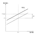
- the relationship between the command value given to the control device 200 in advance and the actual compression ratio is the relationship indicated by the solid line in FIG.
- a command is sent to the variable compression ratio mechanism (the compression ratio controller 106 that controls the link mechanism 105) to realize the target compression ratio ⁇ target. Even if the value ⁇ c is input, the actual compression ratio becomes ⁇ r.
- the target compression ratio ⁇ target is realized by correcting the command value ⁇ c based on the value ⁇ / K obtained by dividing ⁇ by the obtained slope K of the control characteristic. That is, the control device 200 according to the present embodiment determines the difference between the calculated compression ratio ⁇ r and the target compression ratio ⁇ target when the compression ratio ⁇ r calculated by the compression ratio calculation unit 206 is different from the preset target compression ratio ⁇ target.
- the compression ratio control command value ⁇ c for variably controlling the variable compression ratio mechanism is corrected. More specifically, the control device 200 of the present embodiment is a value obtained by dividing the difference ⁇ between the compression ratio ⁇ r calculated by the compression ratio calculation unit 206 and the target compression ratio ⁇ target by the slope K of the control characteristic obtained in advance. Based on ⁇ / K, the compression ratio control command value ⁇ c for variably controlling the variable compression ratio mechanism is corrected. With this configuration, the target compression ratio ⁇ target can be realized.
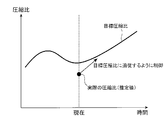
- the target compression ratio ⁇ target is not constant, and changes depending on the operating state of the internal combustion engine 100 such as the rotation speed and load. For example, as shown by the solid line in FIG. 12, when the target compression ratio ⁇ target is given and the actual compression ratio ⁇ is estimated by the compression ratio calculator 206, the compression ratio control command value calculator 207 calculates the compression ratio.
- the target compression ratio ⁇ target can also be realized by controlling the compression ratio control command value so that ⁇ traces the target compression ratio ⁇ target (target value determined by the operating state of the internal combustion engine 100).
- the estimated value of the compression ratio calculated by the compression ratio calculation unit 206 has applications other than realizing the target compression ratio ⁇ target.
- the link mechanism 105 in addition to manufacturing variations of the link mechanism 105, as a change factor of the compression ratio ⁇ , adhesion of deposits such as soot can be considered. If there is a variable compression ratio mechanism as described above, it may be controlled to correct the change in the compression ratio of the deposit adhering, but there may be no variable compression ratio mechanism. In such a case, instead of controlling the changed compression ratio, the engine 100 can be controlled stably and efficiently by controlling the ignition timing, the air-fuel ratio, or the supercharging pressure in the case of an engine with a turbocharger. Can be controlled.
- the increase in the compression ratio ⁇ can be detected with the above-described configuration.
- the ignition timing of the air-fuel mixture in the cylinder 101 is advanced to the knock limit in order to improve efficiency. If the compression ratio ⁇ rises due to the deposit and becomes larger than a preset target compression ratio ⁇ target in the advanced state, knocking occurs. Therefore, when the ignition timing control command value calculation unit 208 detects an increase in the compression ratio ⁇ , the ignition timing control command value calculation unit 208 controls the command value of the ignition timing control to the spark plug 108 so that the ignition timing is retarded accordingly. By doing so, knocking can be avoided.
- the control device 200 changes the in-cylinder pressure P with respect to the crank angle ⁇ at the timing from when the intake valve 109 is closed until ignition of the air-fuel mixture in the cylinder (cylinder) 101 is started dP.
- the compression ratio ⁇ is calculated based on / d ⁇ . More specifically, the control device 200 calculates the compression ratio ⁇ based on the in-cylinder pressure change rate dP / d ⁇ / P obtained by normalizing the change dP / d ⁇ in the in-cylinder pressure P with respect to the crank angle ⁇ .
- the actual compression ratio ⁇ of the internal combustion engine 100 can be estimated not only when the fuel of the internal combustion engine 100 is cut but also without being affected by the intake air amount and the intake air temperature.
- FIG. 13 shows an internal configuration of another example of the control device 200 shown in FIG.
- the control device 210 shown in FIG. 13 uses the adiabatic change timing determination unit 203 of the control device 200 shown in FIG. 10 to calculate the in-cylinder volume change rate dV / d ⁇ / from the crank angle ⁇ calculated by the crank angle calculation unit 201.
- An extremum timing determination unit 211 that determines a timing ⁇ peak (see FIGS. 6 and 9) at which V (a value obtained by normalizing the change dV / d ⁇ of the in-cylinder volume V with respect to the crank angle ⁇ by the in-cylinder volume V) takes an extreme value. It has been replaced with.
- the configuration other than the extreme value timing determination unit 211 in the control device 210 is substantially the same as each configuration of the control device 200 shown in FIG.
- crank angle calculation unit 201 of the control device 210 calculates a crank angle ⁇ of the crankshaft 103 by acquiring a signal from a crank angle sensor 104 provided on the crankshaft 103.
- the in-cylinder pressure calculation unit 202 calculates a pressure (in-cylinder pressure) P in the cylinder 101 by acquiring a signal from an in-cylinder pressure sensor 107 provided in the cylinder 101.
- the extreme value timing determination unit 211 determines whether or not the crank angle ⁇ calculated by the crank angle calculation unit 201 matches the timing ⁇ peak at which the in-cylinder volume change rate dV / d ⁇ / V takes an extreme value. To do.
- in-cylinder pressure differentiation unit 204 three examples corresponding to different in-cylinder pressures P (different compression ratios) calculated by the in-cylinder pressure calculation unit 202 with respect to the crank angle ⁇ calculated by the crank angle calculation unit 201 are shown in the upper part of FIG.
- the cylinder pressure differential value dP / d ⁇ (the result of differentiating the three cylinder pressures P shown in the upper diagram of FIG. 9 is shown in the middle diagram of FIG. 9) is calculated.
- the in-cylinder pressure change rate calculation unit 205 calculates the in-cylinder pressure differential value calculated by the in-cylinder pressure differentiation unit 204 at the timing when the in-cylinder volume change rate dV / d ⁇ / V determined by the extreme value timing determination unit 211 becomes an extreme value.
- dP / d ⁇ is normalized by the in-cylinder pressure P, and the in-cylinder pressure change rate dP / d ⁇ / P (the results obtained by normalizing the three in-cylinder pressure differential values dP / d ⁇ shown in the middle diagram of FIG. (Shown in the figure).
- dP / d ⁇ is normalized by the in-cylinder pressure P, and the in-cylinder pressure change rate dP / d ⁇ / P (the results obtained by normalizing the three in-cylinder pressure differential values dP / d ⁇ shown in the middle diagram of FIG. (Shown in the figure).
- the compression ratio calculation unit 206 the in-cylinder pressure change rate dP / d ⁇ / P calculated by the in-cylinder pressure change rate calculation unit 205, and the in-cylinder pressure change rate dP / d ⁇ / P determined in advance as shown in FIG.
- the compression ratio (actual compression ratio) ⁇ is calculated from the relationship with the ratio ⁇ .
- the actual compression ratio ⁇ of the internal combustion engine 100 can be estimated without being limited to the time of fuel cut of the internal combustion engine 100 and without being affected by the intake air amount or the intake air temperature. it can.
- the control device 210 of the present embodiment calculates the compression ratio ⁇ based on the change dP / d ⁇ of the in-cylinder pressure P with respect to the crank angle ⁇ at the timing when the in-cylinder volume change rate dV / d ⁇ / V takes an extreme value. . More specifically, the controller 210 calculates the compression ratio ⁇ based on the in-cylinder pressure change rate dP / d ⁇ / P obtained by normalizing the change dP / d ⁇ of the in-cylinder pressure P with respect to the crank angle ⁇ .
- the actual compression ratio ⁇ of the internal combustion engine 100 can be estimated not only at the time of fuel cut of the internal combustion engine 100 but also without being affected by the intake air amount and the intake air temperature, and the estimation accuracy of the compression ratio ⁇ is improved. be able to.
- each of the above-described configurations, functions, processing units, processing means, and the like may be realized by hardware by designing a part or all of them with, for example, an integrated circuit.
- Each of the above-described configurations, functions, and the like may be realized by software by interpreting and executing a program that realizes each function by the processor.
- Information such as programs, tables, and files for realizing each function can be stored in a memory, a hard disk, a storage device such as an SSD (Solid State Drive), or a recording medium such as an IC card, an SD card, or a DVD.
- control lines and information lines indicate what is considered necessary for the explanation, and not all the control lines and information lines on the product are necessarily shown. Actually, it may be considered that almost all the components are connected to each other.
Landscapes
- Engineering & Computer Science (AREA)
- Chemical & Material Sciences (AREA)
- Combustion & Propulsion (AREA)
- Mechanical Engineering (AREA)
- General Engineering & Computer Science (AREA)
- Physics & Mathematics (AREA)
- Fluid Mechanics (AREA)
- Signal Processing (AREA)
- Output Control And Ontrol Of Special Type Engine (AREA)
- Combined Controls Of Internal Combustion Engines (AREA)
- Electrical Control Of Ignition Timing (AREA)
Abstract
内燃機関の燃料カット時のみならず、また、吸気量や吸気温度の影響を受けずに、内燃機関の圧縮比を推定することのできる内燃機関の制御装置を提供する。 筒内体積変化率dV/dθ/Vが極値をとるタイミング、ないし、吸気弁109が閉じてから気筒内の混合気への着火が開始するまでのタイミングにおけるクランク角θに対する筒内圧Pの変化に基づき圧縮比εを算出する。
Description
本発明は、内燃機関の圧縮比を推定する制御装置に係り、特に、圧縮比を可変とする可変圧縮比機構を備えた内燃機関(可変圧縮比内燃機関)の圧縮比を推定する制御装置に関する。
この種の従来技術として、例えば特許文献1には、内燃機関のピストンとクランクシャフトとが複数のリンク部材を介して連結されているとともに、これらのリンク部材の自由度を制限するコントロールリンクを有し、このコントロールリンクの基端がコントロールシャフトの偏心軸に揺動可能に連結され、このコントロールシャフトの回転位置に応じて圧縮比が変化する可変圧縮比内燃機関において、内燃機関の燃料カット中に、上記コントロールシャフトの所定圧縮比状態での保持に必要なトルクのサイクル中のピーク値を求め、このピークトルクから実圧縮比を推定する技術が開示されている。
ところで、上記特許文献1に所載のように、トルクのサイクル中のピーク値(ピークトルク)から圧縮比を推定する方法では、トルクのピーク値は燃焼により発生する熱量の影響を受けるので、内燃機関の燃料カットの場合に限定する必要がある。また、トルクのピーク値は吸気量や吸気温度の影響を受けるので、吸気量や吸気温度を正確に計測するか、あるいは、一定の条件に制約する必要があるという問題がある。
本発明は、前記事情に鑑みてなされたもので、その目的とするところは、内燃機関の燃料カット時のみならず、また、吸気量や吸気温度の影響を受けずに、内燃機関の圧縮比を推定することのできる内燃機関の制御装置を提供することにある。
上記課題を解決するために、本発明に係る内燃機関の制御装置は、ピストンに連結されたクランク軸の回転に同期して吸気弁及び排気弁が開閉する気筒を有する内燃機関の圧縮比を推定する制御装置において、前記吸気弁が閉じてから前記気筒内の混合気への着火が開始されるまでのタイミングにおけるクランク角に対する筒内圧の変化に基づき前記圧縮比を算出することを特徴としている。
本発明によれば、内燃機関の燃料カット時のみならず、また、吸気量や吸気温度の影響を受けずに、内燃機関の圧縮比を推定することができる。
上記した以外の課題、構成及び効果は、以下の実施形態の説明により明らかにされる。
以下、本発明に係る内燃機関の制御装置の実施形態について図面を参照して説明する。
本発明による制御装置が適用される内燃機関(可変圧縮比内燃機関)(以下、エンジンや
可変圧縮比エンジンということもある)を図1に示す。
可変圧縮比エンジンということもある)を図1に示す。
図示実施形態の内燃機関100では、クランク軸103の回転と同期してシリンダ(気筒)101に設けられた吸気弁109、排気弁110が開閉することで、シリンダ101内(筒内もしくは燃焼室内)に空気(吸気)が取り込まれる。取り込んだ空気の中に、インジェクタ106から燃料が噴射され、シリンダ101内に燃料と空気の混合気が生成される。この混合気に点火プラグ108から点火(着火)すると、爆発エネルギーによりピストン102が押し下げられ、このピストン102への押し下げ力がコネクティングロッド111及びリンク機構105を通してクランク軸103に伝えられて、クランク軸103が回転する。クランク軸103の回転は、例えば、不図示のミッションを経てタイヤの回転になり、内燃機関100が搭載された自動車等の推進力となる。
このような内燃機関100において、クランク軸103のクランク角θ(クランク角センサ104により計測されるクランク角θ)と、シリンダ101とピストン102とで囲まれた燃焼室112内の体積(筒内体積)Vとの関係は、図2に示すようになる。すなわち、ピストン102の位置が最も高くなる上死点TDC(Top Dead Center)において体積Vは最小値Vminをとり、ピストン102の位置が最も低くなる下死点BDC(Bottom Dead Center)において体積Vは最大値Vmaxをとる。この最小値Vminと最大値Vmaxの比Vmax/Vminを圧縮比εとよぶ。一般に、圧縮比εが大きいほど、エンジン100は効率が良くなるが、高負荷域で圧縮比εを大きくすると、ノックが発生し、エンジン100の破損につながる。可変圧縮比エンジン100はこのような背景から開発されたもので、低負荷域では圧縮比εを大きくし、高負荷域では圧縮比εを小さくすることで、当該内燃機関100の効率を向上させている。前述のような圧縮比εを可変とする機構(可変圧縮比機構)は、その構成自体はよく知られたものであるが、本実施形態の内燃機関100では、圧縮比コントローラ106により前記リンク機構105を制御することで、コネクティングロッド111とリンク機構105の結合点113とクランク軸103との距離が変化し、前述のクランク角θと体積Vの関係が変化し、これにより、圧縮比εが機械的に可変制御される。当該可変圧縮比エンジン100での、クランク角θと体積Vの関係は、例えば図3に示すようになり、異なる圧縮比ε1、ε2、ε3のそれぞれに対して、クランク角θと体積Vの関係が与えられる。なお、圧縮比εは必ずしも離散ではなく、連続的に変化することもある。
ところで、このような内燃機関100では、リンク機構105の製造ばらつき等の理由により、当該内燃機関100の運転状態を制御する制御装置200(後述する図10、13参照)が指令した圧縮比と、実際に制御された結果の圧縮比とが異なることがあるため、この実際の圧縮比(実圧縮比)εを推定する必要がある。
ここで、内燃機関100の高効率化のためには、当該内燃機関100の燃焼状態を計測して、フィードバックすることが望ましく、最近では、筒内圧センサ107をシリンダ101に取り付けてシリンダ101内の圧力(筒内圧)Pを計測することが検討されている。燃料カット時の筒内圧Pは図4の破線のようになり、燃焼しているときの筒内圧Pは図4の実線のようになる。シリンダ101内の吸気量nと吸気温度Tがわかっていて、筒内圧Pが計測できれば、体積Vは、気体の状態方程式から以下の(式1)で求められる。ただし、Rは空気と燃料の混合気の気体定数である。

そして、筒内圧Pを計測したタイミングでのクランク角θと体積Vから、図3に示す圧縮比ごとのクランク角θと体積Vの関係を参照して、圧縮比εを特定できる。
ところで、前述の圧縮比εの特定方法は、吸気量nと吸気温度Tがわかっていることが前提であるが、実際のエンジン100で、気筒内の温度を計測するのは困難である。また、吸気量を計測するエアフローセンサが付設されているが、エアフローセンサを通過した空気がどのようにエンジン100の各気筒に入っていくのかを推定することも困難である。そこで、本実施形態では、吸気量nや吸気温度Tがわからなくても、圧縮比εを推定する方法を提案する。
シリンダ101に備えられた吸気弁109を閉じてから混合気が着火して燃焼が始まるまでは、シリンダ101内は熱の出入りがない断熱過程と考えることができる。このとき、体積(筒内体積)Vと圧力(筒内圧)Pとの間には、熱力学の分野で広く知られた以下の(式2)で示す関係が成り立つ。

(式2)を、クランク軸103のクランク角θで微分すると、以下の(式3)となる。

(式3)の両辺をP・Vγで割ると、以下の(式4)となる。

図3に示すように、可変圧縮比エンジン100の体積Vとクランク角θの関係は、圧縮比εによってV軸方向に平行移動すると近似できるので、図5に示すdV/dθ(筒内体積(燃焼室内体積)Vをクランク角θで微分した筒内体積微分値)は圧縮比εに依存しない。
一方で、圧縮比ごとのdV/dθ/V(図5に示す筒内体積微分値を筒内体積で正規化した筒内体積変化率)は図6に示すようになり、dV/dθ/Vは、上死点TDCの30°ほど前のθpeakで極値をとり、このときに圧縮比εによる違いが最も大きくなることがわかる。前述のθpeakにおけるdV/dθ/Vと圧縮比εの関係は例えば図7に示すようになる。
ここで、式4より、dP/dθ/P(筒内圧Pをクランク角θで微分した筒内圧微分値を筒内圧Pで正規化した筒内圧変化率)とdV/dθ/Vは比例するので、圧縮比εとdP/dθ/Pとの間には図8の実線に示す関係がある。したがって、図9に示すように、θpeak付近で筒内圧Pを計測し(図9の上段の図)、筒内圧Pをクランク角θで微分して筒内圧微分値dP/dθを算出し(図9の中段の図)、この筒内圧微分値dP/dθを筒内圧Pで正規化して筒内圧変化率dP/dθ/Pを求める(図9の下段の図)。そして、事前に取得しておいた図8に示すような筒内圧変化率dP/dθ/Pと圧縮比εの関係に基づき、実際の圧縮比(実圧縮比)εを推定する。
なお、式4に着目すると、この式4は筒内圧Pと体積Vと比熱比γだけの式である。比熱比γは、気体の成分が決まれば一意に決まる。燃料の成分比が変化しても、この比熱比γはほぼ1.3程度の値なので、式4は運転条件によらず成り立つと考えられる。
また、図9の下段の図(筒内圧変化率dP/dθ/Pを示す図)を注意深く観察すると、dP/dθ/Pは、θpeakのタイミングだけではなく、その前後でも、圧縮比εに依存して変化することがわかる。θpeakの前後Δにおいて、dP/dθ/Pと圧縮比εの関係をプロットすると、例えば図8の破線や一点破線に示すようになる。この関係を用いても、dP/dθ/Pから圧縮比 (実圧縮比)εを推定できることがわかる。
ここで、θpeakの前後どこまでの範囲のdP/dθ/Pが圧縮比εと相関をもつかが問題となるが、式4が成り立つ範囲、すなわち、式2~4の導出の前提とした燃焼室112内が断熱変化している範囲、より詳細には、吸気弁109の閉弁タイミングIVC(Intake Valve Close)から、燃焼室112内の空気と燃料の混合気が着火して熱発生が始まるまでの範囲である(図6及び図9参照)。
なお、上記説明では、筒内圧変化率dP/dθ/Pと筒内体積変化率dV/dθ/Vとが比例するという関係から、筒内圧変化率dP/dθ/Pを求めて実圧縮比εを推定するものとしているが、筒内圧Pと筒内体積Vとの関係が予め取得されていれば、筒内圧Pをクランク角θで微分した筒内圧微分値(つまり、クランク角θに対する筒内圧Pの変化)dP/dθから実圧縮比εを推定(算出)できることは詳述するまでも無い。
上述のように、本実施形態の制御装置200は、吸気弁109が閉じてからシリンダ(気筒)101内の混合気への着火が開始されるまでのタイミングにおけるクランク角θに対する筒内圧Pの変化dP/dθに基づき圧縮比εを算出する。より具体的には、制御装置200は、クランク角θに対する筒内圧Pの変化dP/dθを筒内圧Pで正規化した筒内圧変化率dP/dθ/Pに基づき圧縮比を算出する。これにより、内燃機関100の実際の圧縮比εを推定することができる。
図10は、上述した圧縮比推定を実現する、本発明による制御装置の一実施形態の内部構成を示したものである。
図10に示す制御装置200は、基本的に、入出力ポート、RAM、ROM、CPU等を含むマイクロコンピュータで構成されており、主に、クランク角算出部201と、筒内圧算出部202と、断熱変化タイミング判定部203と、筒内圧微分部204と、筒内圧変化率算出部205と、圧縮比算出部206とを備える。
クランク角算出部201では、クランク軸103に設けられたクランク角センサ104の信号を取得してクランク軸103のクランク角θを算出する。
筒内圧算出部202では、シリンダ101に設けられた筒内圧センサ107の信号を取得してシリンダ101内の圧力(筒内圧)Pを算出する。
断熱変化タイミング判定部203では、前記クランク角算出部201で算出したクランク角θが、燃焼室112内(筒内)が断熱変化するタイミングか否か(すなわち、吸気弁109が閉じてからシリンダ101内の混合気への着火が開始されるまでのタイミングか否か)を判定する。
筒内圧微分部204では、前記クランク角算出部201で算出したクランク角θに対して前記筒内圧算出部202で算出した筒内圧P(異なる圧縮比に対応した3つの例を図9の上段の図に示す)を微分して筒内圧微分値dP/dθ(図9の上段の図に示される3つの筒内圧Pを微分した結果を図9の中段の図に示す)を算出する。
筒内圧変化率算出部205では、前記断熱変化タイミング判定部203で燃焼室112内が断熱変化していると判定したタイミングで、前記筒内圧微分部204で算出した筒内圧微分値dP/dθを筒内圧Pで正規化して筒内圧変化率dP/dθ/P(図9の中段の図に示される3つの筒内圧微分値dP/dθを正規化した結果を図9の下段の図に示す)を算出する。なお、図9では、筒内圧Pから算出した筒内圧変化率dP/dθ/Pを示しているが、この全ての範囲の筒内圧変化率dP/dθ/Pを計算する必要はなく、θpeakもしくはその付近での筒内圧変化率dP/dθ/Pを計算できればよい。
圧縮比算出部206では、前記筒内圧変化率算出部205で算出した筒内圧変化率dP/dθ/Pと、図8に示すような予め求められた筒内圧変化率dP/dθ/Pと圧縮比εとの関係から、圧縮比(実圧縮比)εを算出する。
これにより、内燃機関100の燃料カット時に限定せず、また、吸気量や吸気温度の影響を受けずに、内燃機関100の実際の圧縮比εを推定することができる。
また、本実施形態の制御装置200には、前記圧縮比算出部206で算出(推定)した圧縮比εに基づいてフィードバック制御を行うための構成として、前記圧縮比算出部206で算出した圧縮比εに基づいて、可変圧縮比機構を可変制御するための圧縮比制御の指令値を演算する圧縮比制御指令値演算部207や、前記圧縮比算出部206で算出した圧縮比εに基づいて、前記点火プラグ108によるシリンダ101内の混合気の点火タイミングを制御するための点火タイミング制御の指令値を演算する点火タイミング制御指令値演算部208等が更に備えられている。
前述のように、可変圧縮比エンジン100では、リンク機構105の製造ばらつき等の理由により、制御装置200が指令した圧縮比(目標圧縮比)と、実際に制御された結果の圧縮比(実圧縮比)が異なることがある。例えば、予め制御装置200に与えられた指令値と実圧縮比の関係が図11の実線で示す関係であるとする。ところが、リンク機構105の製造誤差により点線で示す特性に変化していたとすると、目標圧縮比εtargetを実現するために可変圧縮比機構(を構成するリンク機構105を制御する圧縮比コントローラ106)に指令値εcを入力しても、実際の圧縮比はεrになってしまう。
そこで、圧縮比制御指令値演算部207では、前記圧縮比算出部206で算出した圧縮比εrと目標圧縮比εtargetとの差Δε=εtarget-εrを算出し、図11の実線や点線で示す予め求められた制御特性の傾きKでΔεを除した値Δε/Kに基づき指令値εcを補正することで、目標圧縮比εtargetを実現する。すなわち、本実施形態の制御装置200は、圧縮比算出部206で算出された圧縮比εrが予め設定された目標圧縮比εtargetと異なる場合に、算出された圧縮比εrと目標圧縮比εtargetの差Δεに基づき可変圧縮比機構を可変制御するための圧縮比制御の指令値εcを補正する。より具体的には、本実施形態の制御装置200は、圧縮比算出部206で算出された圧縮比εrと目標圧縮比εtargetとの差Δεを予め求められた制御特性の傾きKで除した値Δε/Kに基づき、可変圧縮比機構を可変制御するための圧縮比制御の指令値εcを補正する。この構成により、目標圧縮比εtargetを実現することができる。
また、目標圧縮比εtargetは一定ではなく、回転数・負荷等の内燃機関100の運転状態によっても変化する。例えば、図12の実線で示すように目標圧縮比εtargetが与えられていて、前記圧縮比算出部206で実際の圧縮比εが推定されたら、圧縮比制御指令値演算部207では、その圧縮比εが目標圧縮比εtarget(内燃機関100の運転状態によって定まる目標値)をトレース(追従)するように圧縮比制御の指令値を制御することで、目標圧縮比εtargetを実現することもできる。
また、前記圧縮比算出部206で算出した圧縮比の推定値は、目標圧縮比εtargetを実現する以外の応用もある。
例えば、リンク機構105の製造ばらつき以外に、圧縮比εの変化要因としては、すす等の堆積物の付着も考えられる。前記のような可変圧縮比機構があれば、これを制御して、堆積物の付着分の圧縮比変化を補正すればよいが、可変圧縮比機構がない場合もあり得る。このような場合には、変化した圧縮比を制御する代わりに、点火タイミング、空燃比、あるいはターボチャージャがついたエンジンなら過給圧等を制御することで、エンジン100を安定に且つ効率的に制御することができる。
例えば、すす等の堆積物によって圧縮比εが上昇してしまったとすると、その圧縮比εの上昇は、前述の構成にて検出できる。
通常のエンジンでは、効率を良くするために、シリンダ101内の混合気の点火タイミングをノック限界まで進角させている。進角させた状態で、堆積物により圧縮比εが上昇して予め設定された目標圧縮比εtargetより大きくなってしまったらノックが発生してしまう。そこで、前記点火タイミング制御指令値演算部208では、圧縮比εの上昇を検知したときに、これに応じて点火タイミングを遅角するように前記点火プラグ108への点火タイミング制御の指令値を制御することで、ノックを回避することができる。
このように、本実施形態の制御装置200は、吸気弁109が閉じてからシリンダ(気筒)101内の混合気への着火が開始されるまでのタイミングにおけるクランク角θに対する筒内圧Pの変化dP/dθに基づき圧縮比εを算出する。より具体的には、制御装置200は、クランク角θに対する筒内圧Pの変化dP/dθを筒内圧Pで正規化した筒内圧変化率dP/dθ/Pに基づき圧縮比εを算出する。これにより、内燃機関100の燃料カット時のみならず、また、吸気量や吸気温度の影響を受けずに、内燃機関100の実際の圧縮比εを推定することができる。
図13は、図10に示す制御装置200の他例の内部構成を示したものである。
図13に示す制御装置210は、図10に示す制御装置200の断熱変化タイミング判定部203を、クランク角算出部201で算出したクランク角θから、予め入力した筒内体積変化率dV/dθ/V(クランク角θに対する筒内体積Vの変化dV/dθを筒内体積Vで正規化した値)が極値をとるタイミングθpeak(図6及び図9参照)を判定する極値タイミング判定部211に置き換えたものである。なお、制御装置210における極値タイミング判定部211以外の構成は、上記図10に示す制御装置200の各構成とほぼ同じである。
詳しくは、制御装置210のクランク角算出部201では、クランク軸103に設けられたクランク角センサ104の信号を取得してクランク軸103のクランク角θを算出する。
筒内圧算出部202では、シリンダ101に設けられた筒内圧センサ107の信号を取得してシリンダ101内の圧力(筒内圧)Pを算出する。
極値タイミング判定部211では、前記クランク角算出部201で算出したクランク角θが、予め入力した筒内体積変化率dV/dθ/Vが極値をとるタイミングθpeakと一致するか否かを判定する。
筒内圧微分部204では、前記クランク角算出部201で算出したクランク角θに対して前記筒内圧算出部202で算出した筒内圧P(異なる圧縮比に対応した3つの例を図9の上段の図に示す)を微分して筒内圧微分値dP/dθ(図9の上段の図に示される3つの筒内圧Pを微分した結果を図9の中段の図に示す)を算出する。
筒内圧変化率算出部205では、前記極値タイミング判定部211で判定した筒内体積変化率dV/dθ/Vが極値となるタイミングで、前記筒内圧微分部204で算出した筒内圧微分値dP/dθを筒内圧Pで正規化して筒内圧変化率dP/dθ/P(図9の中段の図に示される3つの筒内圧微分値dP/dθを正規化した結果を図9の下段の図に示す)を算出する。なお、図9では、筒内圧Pから算出した筒内圧変化率dP/dθ/Pを示しているが、この全ての範囲の筒内圧変化率dP/dθ/Pを計算する必要はなく、θpeakでの筒内圧変化率dP/dθ/Pを計算できればよい。
圧縮比算出部206では、前記筒内圧変化率算出部205で算出した筒内圧変化率dP/dθ/Pと、図8に示すような予め求められた筒内圧変化率dP/dθ/Pと圧縮比εとの関係から、圧縮比(実圧縮比)εを算出する。
これにより、図10に示す例と同様、内燃機関100の燃料カット時に限定せず、また、吸気量や吸気温度の影響を受けずに、内燃機関100の実際の圧縮比εを推定することができる。
このように、本実施形態の制御装置210は、筒内体積変化率dV/dθ/Vが極値をとるタイミングにおけるクランク角θに対する筒内圧Pの変化dP/dθに基づき圧縮比εを算出する。より具体的には、制御装置210は、クランク角θに対する筒内圧Pの変化dP/dθを筒内圧Pで正規化した筒内圧変化率dP/dθ/Pに基づき圧縮比εを算出する。これにより、内燃機関100の燃料カット時のみならず、また、吸気量や吸気温度の影響を受けずに、内燃機関100の実際の圧縮比εを推定できるとともに、圧縮比εの推定精度を高めることができる。
なお、本発明は上記した実施形態に限定されるものではなく、様々な変形形態が含まれる。例えば、上記した実施形態は本発明を分かりやすく説明するために詳細に説明したものであり、必ずしも説明した全ての構成を備えるものに限定されるものではない。
また、上記の各構成、機能、処理部、処理手段等は、それらの一部又は全部を、例えば集積回路で設計する等によりハードウェアで実現してもよい。また、上記の各構成、機能等は、プロセッサがそれぞれの機能を実現するプログラムを解釈し、実行することによりソフトウェアで実現してもよい。各機能を実現するプログラム、テーブル、ファイル等の情報は、メモリや、ハードディスク、SSD(Solid State Drive)等の記憶装置、または、ICカード、SDカード、DVD等の記録媒体に置くことができる。
また、制御線や情報線は説明上必要と考えられるものを示しており、製品上必ずしも全ての制御線や情報線を示しているとは限らない。実際には殆ど全ての構成が相互に接続されていると考えてもよい。
100…内燃機関
101…シリンダ
101…ピストン
103…クランク軸
104…クランク角センサ
105…リンク機構
106…インジェクタ
107…筒内圧センサ
108…点火プラグ
109…吸気弁
110…排気弁
111…コネクティングロッド
112…燃焼室
113…結合点
200、210…制御装置
201…クランク角算出部
202…筒内圧算出部
203…断熱変化タイミング判定部
204…筒内圧微分部
205…筒内圧変化率算出部
206…圧縮比算出部
207…圧縮比制御指令値演算部
208…点火タイミング制御指令値演算部
211…極値タイミング判定部
101…シリンダ
101…ピストン
103…クランク軸
104…クランク角センサ
105…リンク機構
106…インジェクタ
107…筒内圧センサ
108…点火プラグ
109…吸気弁
110…排気弁
111…コネクティングロッド
112…燃焼室
113…結合点
200、210…制御装置
201…クランク角算出部
202…筒内圧算出部
203…断熱変化タイミング判定部
204…筒内圧微分部
205…筒内圧変化率算出部
206…圧縮比算出部
207…圧縮比制御指令値演算部
208…点火タイミング制御指令値演算部
211…極値タイミング判定部
Claims (12)
- ピストンに連結されたクランク軸の回転に同期して吸気弁及び排気弁が開閉する気筒を有する内燃機関の圧縮比を推定する制御装置において、
前記吸気弁が閉じてから前記気筒内の混合気への着火が開始されるまでのタイミングにおけるクランク角に対する筒内圧の変化に基づき前記圧縮比を算出することを特徴とする内燃機関の制御装置。 - 請求項1に記載の内燃機関の制御装置において、
クランク角に対する筒内圧の変化を筒内圧で正規化した筒内圧変化率に基づき前記圧縮比を算出することを特徴とする内燃機関の制御装置。 - 請求項2に記載の内燃機関の制御装置において、
予め求められた前記筒内圧変化率と前記圧縮比の関係から前記圧縮比を算出することを特徴とする内燃機関の制御装置。 - 請求項1に記載の内燃機関の制御装置において、
クランク角に対する筒内体積の変化を筒内体積で正規化した筒内体積変化率が極値をとるタイミングにおけるクランク角に対する筒内圧の変化に基づき前記圧縮比を算出することを特徴とする内燃機関の制御装置。 - 請求項1に記載の内燃機関の制御装置において、
前記内燃機関には、前記圧縮比を可変とする可変圧縮比機構が備えられており、
前記制御装置は、算出された圧縮比が予め設定された目標圧縮比と異なる場合に、前記算出された圧縮比と前記目標圧縮比の差に基づき前記可変圧縮比機構を可変制御するための圧縮比制御の指令値を補正することを特徴とする内燃機関の制御装置。 - 請求項5に記載の内燃機関の制御装置において、
前記制御装置は、前記算出された圧縮比と前記目標圧縮比の差を予め求められた制御特性の傾きで除した値に基づき前記圧縮比制御の指令値を補正することを特徴とする内燃機関の制御装置。 - 請求項1に記載の内燃機関の制御装置において、
前記内燃機関には、前記圧縮比を可変とする可変圧縮比機構が備えられており、
前記制御装置は、算出された圧縮比が前記内燃機関の運転状態によって定まる目標値に追従するように前記可変圧縮比機構を可変制御するための圧縮比制御の指令値を制御することを特徴とする内燃機関の制御装置。 - 請求項1に記載の内燃機関の制御装置において
算出された圧縮比が予め設定された目標圧縮比より大きい場合に、前記気筒内の混合気の点火タイミングを遅くするように点火タイミング制御の指令値を制御することを特徴とする内燃機関の制御装置。 - ピストンに連結されたクランク軸の回転に同期して吸気弁及び排気弁が開閉する気筒を有する内燃機関の圧縮比を推定する制御装置において、
前記クランク軸のクランク角を算出するクランク角算出部と、
前記気筒の筒内圧を算出する筒内圧算出部と、
前記クランク角算出部で算出したクランク角から、前記吸気弁が閉じてから前記気筒内の混合気への着火が開始されるまでのタイミングを判定する断熱変化タイミング判定部と、
前記クランク角算出部で算出したクランク角に対して前記筒内圧算出部で算出した筒内圧を微分して筒内圧微分値を算出する筒内圧微分部と、
前記断熱変化タイミング判定部で判定したタイミングで、前記筒内圧微分値を筒内圧で正規化して筒内圧変化率を算出する筒内圧変化率算出部と、
前記筒内圧変化率算出部で算出した筒内圧変化率に基づいて前記圧縮比を算出する圧縮比算出部と、を備えることを特徴とする内燃機関の制御装置。 - 請求項9に記載の内燃機関の制御装置において、
前記圧縮比算出部で算出した圧縮比に基づいて、前記圧縮比を可変とする可変圧縮比機構を可変制御するための圧縮比制御の指令値を演算する圧縮比制御指令値演算部、及び/又は、前記圧縮比算出部で算出した圧縮比に基づいて、前記気筒内の混合気の点火タイミングを制御するための点火タイミング制御の指令値を演算する点火タイミング制御指令値演算部を更に備えることを特徴とする内燃機関の制御装置。 - ピストンに連結されたクランク軸の回転に同期して吸気弁及び排気弁が開閉する気筒を有する内燃機関の圧縮比を推定する制御装置において、
前記クランク軸のクランク角を算出するクランク角算出部と、
前記気筒の筒内圧を算出する筒内圧算出部と、
前記クランク角算出部で算出したクランク角から、クランク角に対する筒内体積の変化を筒内体積で正規化した筒内体積変化率が極値をとるタイミングを判定する極値タイミング判定部と、
前記クランク角算出部で算出したクランク角に対して前記筒内圧算出部で算出した筒内圧を微分して筒内圧微分値を算出する筒内圧微分部と、
前記極値タイミング判定部で判定したタイミングで、前記筒内圧微分値を筒内圧で正規化して筒内圧変化率を算出する筒内圧変化率算出部と、
前記筒内圧変化率算出部で算出した筒内圧変化率に基づいて前記圧縮比を算出する圧縮比算出部と、を備えることを特徴とする内燃機関の制御装置。 - 請求項11に記載の内燃機関の制御装置において、
前記圧縮比算出部で算出した圧縮比に基づいて、前記圧縮比を可変とする可変圧縮比機構を可変制御するための圧縮比制御の指令値を演算する圧縮比制御指令値演算部、及び/又は、前記圧縮比算出部で算出した圧縮比に基づいて、前記気筒内の混合気の点火タイミングを制御するための点火タイミング制御の指令値を演算する点火タイミング制御指令値演算部を更に備えることを特徴とする内燃機関の制御装置。
Priority Applications (1)
| Application Number | Priority Date | Filing Date | Title |
|---|---|---|---|
| US16/607,269 US11073092B2 (en) | 2017-05-10 | 2018-01-31 | Control device for internal combustion engine |
Applications Claiming Priority (2)
| Application Number | Priority Date | Filing Date | Title |
|---|---|---|---|
| JP2017094177A JP7101460B2 (ja) | 2017-05-10 | 2017-05-10 | 内燃機関の制御装置 |
| JP2017-094177 | 2017-05-10 |
Publications (1)
| Publication Number | Publication Date |
|---|---|
| WO2018207412A1 true WO2018207412A1 (ja) | 2018-11-15 |
Family
ID=64105143
Family Applications (1)
| Application Number | Title | Priority Date | Filing Date |
|---|---|---|---|
| PCT/JP2018/003105 Ceased WO2018207412A1 (ja) | 2017-05-10 | 2018-01-31 | 内燃機関の制御装置 |
Country Status (3)
| Country | Link |
|---|---|
| US (1) | US11073092B2 (ja) |
| JP (1) | JP7101460B2 (ja) |
| WO (1) | WO2018207412A1 (ja) |
Citations (2)
| Publication number | Priority date | Publication date | Assignee | Title |
|---|---|---|---|---|
| JP2005140054A (ja) * | 2003-11-07 | 2005-06-02 | Toyota Motor Corp | 内燃機関の制御装置 |
| WO2014141729A1 (ja) * | 2013-03-13 | 2014-09-18 | 日産自動車株式会社 | 内燃機関の制御装置および制御方法 |
Family Cites Families (12)
| Publication number | Priority date | Publication date | Assignee | Title |
|---|---|---|---|---|
| FR2448032A1 (fr) * | 1979-02-05 | 1980-08-29 | Semt | Procede pour ameliorer le rendement d'un moteur a combustion interne notamment suralimente |
| MY146539A (en) * | 2003-06-20 | 2012-08-15 | Scuderi Group Llc | Split-cycle four-stroke engine |
| CN100476180C (zh) * | 2003-10-09 | 2009-04-08 | Avl里斯脱有限公司 | 内燃机的工作方法 |
| JP2006342677A (ja) * | 2005-06-07 | 2006-12-21 | Hitachi Ltd | 圧縮着火エンジン |
| JP4525517B2 (ja) * | 2005-08-08 | 2010-08-18 | トヨタ自動車株式会社 | 内燃機関 |
| JP2007113485A (ja) * | 2005-10-20 | 2007-05-10 | Hitachi Ltd | 内燃機関の制御方法及び制御装置 |
| US8527183B2 (en) * | 2007-09-20 | 2013-09-03 | General Electric Company | System and method for controlling the fuel injection event in an internal combustion engine |
| WO2009149044A2 (en) * | 2008-06-03 | 2009-12-10 | Bryant, Mark, Curtis | Internal combustion engine and working cycle |
| JP5152015B2 (ja) | 2009-01-30 | 2013-02-27 | 日産自動車株式会社 | 可変圧縮比内燃機関の制御装置 |
| MX340771B (es) * | 2013-01-17 | 2016-07-26 | Nissan Motor | Dispositivo de control de motor de combustion interna y metodo de control. |
| EP3109457B1 (en) * | 2014-02-17 | 2018-06-20 | Nissan Motor Co., Ltd | Ignition device and ignition method for internal combustion engine |
| DE102015207252A1 (de) * | 2015-04-21 | 2016-10-27 | Avl List Gmbh | Verfahren und Vorrichtung zur modellbasierten Optimierung einer technischen Einrichtung |
-
2017
- 2017-05-10 JP JP2017094177A patent/JP7101460B2/ja not_active Expired - Fee Related
-
2018
- 2018-01-31 WO PCT/JP2018/003105 patent/WO2018207412A1/ja not_active Ceased
- 2018-01-31 US US16/607,269 patent/US11073092B2/en not_active Expired - Fee Related
Patent Citations (2)
| Publication number | Priority date | Publication date | Assignee | Title |
|---|---|---|---|---|
| JP2005140054A (ja) * | 2003-11-07 | 2005-06-02 | Toyota Motor Corp | 内燃機関の制御装置 |
| WO2014141729A1 (ja) * | 2013-03-13 | 2014-09-18 | 日産自動車株式会社 | 内燃機関の制御装置および制御方法 |
Also Published As
| Publication number | Publication date |
|---|---|
| JP2018189058A (ja) | 2018-11-29 |
| US11073092B2 (en) | 2021-07-27 |
| JP7101460B2 (ja) | 2022-07-15 |
| US20200300184A1 (en) | 2020-09-24 |
Similar Documents
| Publication | Publication Date | Title |
|---|---|---|
| US10001071B2 (en) | Control system and control method for internal combustion engine | |
| US9903287B2 (en) | Control apparatus for internal combustion engine | |
| EP2119894B1 (en) | Controller of internal combustion engine | |
| JP6262957B2 (ja) | 内燃機関の運用方法 | |
| US10018531B2 (en) | Control apparatus and control method for internal combustion engine | |
| WO2007013663A1 (en) | Internal combustion engine control apparatus | |
| US9903302B2 (en) | Control device for internal combustion engine | |
| JP5944249B2 (ja) | 内燃機関の内部egr量算出装置 | |
| EP3078840A1 (en) | Control apparatus for internal combustion engine | |
| CN102822487B (zh) | 内燃机的控制装置 | |
| CN104603428A (zh) | 内燃机的控制装置 | |
| US7121260B2 (en) | Ignition timing control apparatus for engine | |
| US10808630B2 (en) | Control device for internal combustion engine | |
| JPWO2011036743A1 (ja) | 内燃機関の制御装置 | |
| CN108571389B (zh) | 内燃机的控制装置 | |
| JP7101460B2 (ja) | 内燃機関の制御装置 | |
| JP2007291959A (ja) | 内燃機関の制御装置 | |
| JP6845067B2 (ja) | 内燃機関制御装置 | |
| JP7593869B2 (ja) | 内燃機関制御装置 | |
| KR100507203B1 (ko) | 가솔린 엔진의 노킹 제어 장치 및 방법 | |
| JP4803099B2 (ja) | 可変圧縮比エンジンのトルク推定装置 |
Legal Events
| Date | Code | Title | Description |
|---|---|---|---|
| 121 | Ep: the epo has been informed by wipo that ep was designated in this application |
Ref document number: 18799211 Country of ref document: EP Kind code of ref document: A1 |
|
| NENP | Non-entry into the national phase |
Ref country code: DE |
|
| 122 | Ep: pct application non-entry in european phase |
Ref document number: 18799211 Country of ref document: EP Kind code of ref document: A1 |