WO2018207399A1 - 乾燥方法及び乾燥装置 - Google Patents
乾燥方法及び乾燥装置 Download PDFInfo
- Publication number
- WO2018207399A1 WO2018207399A1 PCT/JP2017/045714 JP2017045714W WO2018207399A1 WO 2018207399 A1 WO2018207399 A1 WO 2018207399A1 JP 2017045714 W JP2017045714 W JP 2017045714W WO 2018207399 A1 WO2018207399 A1 WO 2018207399A1
- Authority
- WO
- WIPO (PCT)
- Prior art keywords
- dried
- drying
- coal
- chamber
- fluidized
- Prior art date
- Legal status (The legal status is an assumption and is not a legal conclusion. Google has not performed a legal analysis and makes no representation as to the accuracy of the status listed.)
- Ceased
Links
Images




Classifications
-
- F—MECHANICAL ENGINEERING; LIGHTING; HEATING; WEAPONS; BLASTING
- F23—COMBUSTION APPARATUS; COMBUSTION PROCESSES
- F23K—FEEDING FUEL TO COMBUSTION APPARATUS
- F23K1/00—Preparation of lump or pulverulent fuel in readiness for delivery to combustion apparatus
- F23K1/04—Heating fuel prior to delivery to combustion apparatus
-
- F—MECHANICAL ENGINEERING; LIGHTING; HEATING; WEAPONS; BLASTING
- F26—DRYING
- F26B—DRYING SOLID MATERIALS OR OBJECTS BY REMOVING LIQUID THEREFROM
- F26B17/00—Machines or apparatus for drying materials in loose, plastic, or fluidised form, e.g. granules, staple fibres, with progressive movement
- F26B17/10—Machines or apparatus for drying materials in loose, plastic, or fluidised form, e.g. granules, staple fibres, with progressive movement with movement performed by fluid currents, e.g. issuing from a nozzle, e.g. pneumatic, flash, vortex or entrainment dryers
-
- F—MECHANICAL ENGINEERING; LIGHTING; HEATING; WEAPONS; BLASTING
- F26—DRYING
- F26B—DRYING SOLID MATERIALS OR OBJECTS BY REMOVING LIQUID THEREFROM
- F26B3/00—Drying solid materials or objects by processes involving the application of heat
- F26B3/02—Drying solid materials or objects by processes involving the application of heat by convection, i.e. heat being conveyed from a heat source to the materials or objects to be dried by a gas or vapour, e.g. air
- F26B3/06—Drying solid materials or objects by processes involving the application of heat by convection, i.e. heat being conveyed from a heat source to the materials or objects to be dried by a gas or vapour, e.g. air the gas or vapour flowing through the materials or objects to be dried
- F26B3/08—Drying solid materials or objects by processes involving the application of heat by convection, i.e. heat being conveyed from a heat source to the materials or objects to be dried by a gas or vapour, e.g. air the gas or vapour flowing through the materials or objects to be dried so as to loosen them, e.g. to form a fluidised bed
Definitions
- the present invention relates to a drying method and a drying apparatus.
- a part of the dried product (pre-dried product) obtained by drying lignite (subject to be dried) in the drying chamber is returned to the supply line or the supply hopper, and then the drying chamber. To supply. Thereby, the moisture content as the brown coal supplied to a drying chamber and the whole dried material falls. As a result, it becomes difficult for lignite to adhere to the drying chamber, and the entrance of the drying chamber is prevented from being clogged.
- fluidized steam is introduced into the lignite so that the lignite flows and forms a fluidized bed.
- lignite is dried by the heat transfer member provided in the drying chamber. The dried lignite becomes product coal and is used as a raw material for boilers and the like. A part of the dried lignite is supplied to the drying chamber as the aforementioned dried product.
- the lignite adheres or stays in the fluidized bed depending on the amount of moisture contained in the lignite and the amount of lignite treated.
- the lignite supplied into the drying chamber may stay in the drying chamber and a part of the lignite may not be dried.
- the present invention has been made in view of such problems, and is capable of uniformly drying an object to be dried regardless of the amount of moisture contained in the object to be dried and the amount of the object to be dried. It is an object to provide a method and a drying device.
- the drying method of the present invention is a drying method for drying an object to be dried containing moisture in a drying apparatus having at least a fluidizing chamber and a mixing chamber,
- the pre-dried product obtained by pre-drying the material to be dried is supplied to the fluidization chamber and further fluidized to obtain a fluidized pre-dried product,
- the fluidized pre-dried material is moved to the fluidized pre-dried material in a state where the fluidized pre-dried material is moved into the mixing chamber which is partitioned by the partition and communicates with each other through a through hole formed in a lower portion of the partition.
- the material to be dried is mixed from above the through hole.
- the drying apparatus of the present invention is a drying apparatus that dries an object to be dried containing moisture, A drying chamber having at least a fluidizing chamber and a mixing chamber that is partitioned by a partition and communicates with each other through a through-hole formed in a lower portion of the partition; A pre-dried product supply unit for supplying a pre-dried product obtained by previously drying the material to be dried into the fluidizing chamber; A fluidizing section for further fluidizing the pre-dried product supplied into the drying chamber into a fluidized pre-dried product in the fluidizing chamber; The fluidized pre-dried material moved from the fluidizing chamber to the mixing chamber through the through hole is provided with a material to be dried supplying unit for mixing the material to be dried from above the through hole. .
- the fluidized pre-dried material is obtained by drying the material to be dried in advance and further fluidizing it. For this reason, by mixing a to-be-dried material with this fluidized pre-dried material, the to-be-dried material is efficiently fluidized, and the to-be-dried material in a fluidized state is dried. Further, the material to be dried is mixed with the fluidized pre-dried material in the mixing chamber in a state where the fluidized pre-dried material is more reliably fluidized in the fluidizing chamber.
- the pre-dried product may be fluidized by supplying a drying gas that flows upward from below to the pre-dried product.
- the fluidizing unit fluidizes the pre-dried product by supplying a drying gas that flows upward from below to the pre-dried product supplied to the drying chamber. You may let them.
- the pre-dried product may adhere to the lower part of the drying chamber or the like due to its own weight.
- the fluid to be dried may be mixed with the material to be dried from above or from the side.
- the to-be-dried material supply unit may mix the to-be-dried material with the fluidized pre-dried material from above or from the side. According to these inventions, the direction in which the drying gas is supplied to the pre-dried product differs from the direction in which the material to be dried is mixed with the fluidized pre-dried product.
- the pre-dried material may be obtained from a third chamber which is partitioned from the mixing chamber by a second partition and communicates with each other through a second through hole formed in the second partition.
- the drying chamber has a third chamber that is partitioned from the mixing chamber by a second partition and communicates with each other through a second through hole formed in the second partition, An end portion of the pre-dried material supply unit may be connected to a side plate of the third chamber.
- the pre-dried product may be dried while further fluidizing a pre-dried large-diameter product having a particle size equal to or larger than a reference value to obtain the fluidized pre-dried product.
- the inventors have found that among pre-dried products, those having a larger particle size than those having a smaller particle size contain a higher proportion of moisture. When the ratio of the water content is small, the temperature of the pre-dried product is likely to rise when the pre-dried product is heated.
- the fluidized pre-dried product may be obtained by further drying while fluidizing a reference ratio of the pre-dried large-diameter product.
- the drying apparatus classifies the pre-dried product dried in the drying chamber based on a particle size, and the pre-dried large-diameter product having a particle size equal to or larger than a reference value among the pre-dried products. You may provide the classification part supplied to a predried material supply part.
- the classification unit may be a sieving classifier.
- the drying apparatus may include a classified coal flow rate adjusting unit that supplies an amount of a reference ratio of the pre-dried large-diameter product to the pre-dried product supply unit.
- the material to be dried is uniformly dried regardless of the amount of moisture contained in the material to be dried and the processing amount of the material to be dried. Can be made. Further, the material to be dried can be mixed in a state where the fluidized pre-dried material has been fluidized more reliably. According to the drying method as described in said (3) and the drying apparatus as described in said (4), a pre-dried material can be efficiently fluidized. According to the drying method described in the above (5) and the drying apparatus described in the above (6), an object to be dried to be mixed with the fluidized predried material is hindered with respect to the drying gas supplied to the predried material. Can be made difficult.
- the fluidized premixed material is dried in the mixing chamber in a state where the fluidized predried material is more reliably fluidized. Things can be mixed. According to the drying method as described in said (9) and (10), it can suppress that the ratio of the water
- the present drying apparatus is for continuously drying coal (substance to be dried) having a high water content such as lignite.
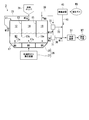
- the drying apparatus 1 of the present embodiment includes a drying chamber 11 and a return pipe (predrying) that supplies the drying chamber 11 with dry coal (pre-dried material) W1 obtained by previously drying coal.
- Material supply unit) 21, fluidized unit 26 which is dried while further fluidizing dry coal W1 supplied into drying chamber 11 to make fluidized coal (fluidized pre-dried product) W2, fluidized coal
- the drying chamber 11 is divided into a first chamber (fluidization chamber) 12, a second chamber (mixing chamber) 14 partitioned by a partition 13 from the first chamber 12, and a partition 15 from a second chamber 14.
- a third chamber 16 The first chamber 12, the second chamber 14, and the third chamber 16 are arranged, for example, along a horizontal plane.
- a dispersion plate 17 is used for the bottom plates of the first chamber 12, the second chamber 14, and the third chamber 16.
- the dispersion plate 17 has a plurality of communication holes 17a penetrating in the vertical direction. For example, one communication hole 17 a is formed below each of the chambers 12, 14, and 16.
- a through hole 13 a is formed in the lower part of the partition 13.
- the first chamber 12 and the second chamber 14 communicate with each other through the through hole 13 a of the partition 13.
- a through hole 15 a is formed in the lower part of the partition 15.
- the second chamber 14 and the third chamber 16 communicate with each other through the through hole 15 a of the partition 15.
- the first end of the return pipe 21 is connected to, for example, a side plate (reference numeral omitted) of the first chamber 12 opposite to the second chamber 14.
- the second end of the return pipe 21 is connected to an intermediate part along the longitudinal direction of the product transport pipe 36 described later.
- the return pipe 21 supplies the dry coal W ⁇ b> 1 into the first chamber 12.
- the fluidizing section 26 is provided with a drying gas generator 27 that generates the drying gas W6 and a drying gas that is provided below the dispersion plate 17 and is supplied with the drying gas W6 generated by the drying gas generator 27.
- Chamber 28 In this embodiment, water vapor is used as the drying gas W6, but high-temperature air or the like may be used as the drying gas W6.
- the drying gas generator 27 a known device such as a boiler can be used.
- a heat exchanger or the like provided in a cooling device 37 described later may be used. By cooling the dry coal W1 with the cooling water in the heat exchanger, the cooling water is heated and the drying gas W6 can be obtained.
- the top plate of the drying gas chamber 28 is the dispersion plate 17 described above. In the present embodiment, an example is shown in which the drying gas chamber 28 is divided into three chambers corresponding to the respective chambers 12, 14, and 16. The drying gas chamber 28 communicates with the chambers 12, 14, and 16 through the communication holes 17 a of the dispersion plate 17.
- the supply hopper 31 is connected to the top plate of the second chamber 14.
- a first end portion of the product transfer pipe 36 is connected to a side plate of the third chamber 16 opposite to the second chamber 14.
- a second end of the product conveyance pipe 36 is connected to a cooling device 37.
- a first end of the steam pipe 39 is connected to the top plate of the third chamber 16.
- a second end of the steam pipe 39 is connected to the dust collector 40.
- a first end of a connecting pipe 41 is connected to the dust collector 40.
- a second end of the connection pipe 41 is connected to an intermediate part of the product transport pipe 36.
- dry coal W1 is obtained by previously drying coal W3.
- the return pipe 21 supplies the dry coal W ⁇ b> 1 into the first chamber 12.
- the drying gas generator 27 of the fluidizing unit 26 generates a drying gas W6.
- the drying gas W6 is supplied to the drying gas chamber 28 and supplied to the chambers 12, 14, 16 of the drying chamber 11 through the communication holes 17a of the dispersion plate 17.
- the drying gas W ⁇ b> 6 that flows from the lower side to the upper side is supplied to the dry coal W ⁇ b> 1 through the communication holes 17 a of the dispersion plate 17.
- the dry coal W1 is further dried while fluidizing.
- the dried coal W1 is further fluidized and dried to obtain fluidized coal W2.
- the dry coal W1 may adhere to the lower dispersion plate 17 or the like of the first chamber 12 or the like due to its own weight.
- the drying gas W6 is supplied not only into the first chamber 12 but also into the second chamber 14 and the third chamber 16 so as to flow upward from below.
- the fluidization mentioned here means a state where coal or the like is flowing without moving inside the room or inside the pipe.
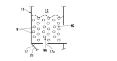
- the dry coal W1 is fluidized by the drying gas W6 in the first chamber 12
- the dry coal W1 is placed on the dispersion plate 17 or the side plate below the first chamber 12, as shown in FIG. It moves without sticking.
- the fluidized coal W2 forms a fluidized bed in which the dry coal W1 floats in the drying gas W6.
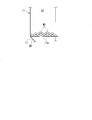
- the dry coal W1 is not fluidized by the drying gas W6, as shown in FIG. 3, the dry coal W1 does not flow in the first chamber 12, but the weight of the dry coal W1 or the dry coal It adheres to the dispersion plate 17 or the like due to the adhesive force of W1 or the like.
- the fluidizing unit 26 supplies the dry coal W1 flowing in the first chamber 12 to the dry coal W1 supplied in the first chamber 12, thereby supplying the dry coal W1 in the first chamber 12. Fluidize. In a state where the dry coal W1 is supplied into the first chamber 12, the dry coal W1 is changed to fluidized coal W2.
- the fluidized coal W ⁇ b> 2 moves from the first chamber 12 to the second chamber 14 through the through hole 13 a formed in the partition 13.
- the supply hopper 31 mixes the coal W3 with the fluidized coal W2 that has moved to the second chamber 14. That is, in the state where the fluidized coal W2 is moved into the second chamber 14, the coal W3 is mixed with the fluidized coal W2. At this time, the supply hopper 31 mixes the coal W3 with the fluidized coal W2 from above.
- the fluidized coal W2 is obtained by drying the coal W3 in advance while further drying the coal W3. For this reason, the coal W3 is efficiently fluidized by mixing the fluidized coal W2 with the fluidized coal W2 in the second chamber 14, and the fluidized coal W3 is dried.
- the direction from the lower side which is the direction in which the drying gas W6 is supplied to the dry coal W1
- the direction from the upper side which is the direction in which the coal W3 is supplied to the fluidized coal W2
- the drying chamber 11 includes the first chamber 12, the partition 13, and the second chamber 14
- the fluidized coal W2 is fluidized in the first chamber 12 in a state where the fluidized coal W2 is fluidized more reliably.
- Coal W3 is mixed with coal W2.
- the fluidized coal W2 is dried in the second chamber 14 while further fluidized by the drying gas W6.
- the fluidized coal W2 and the coal W3 move from the second chamber 14 to the third chamber 16 through the through holes 15a formed in the partition 15.
- the fluidized coal W2 and the coal W3 are dried while further fluidized in the third chamber 16 by the drying gas W6.
- Part of the dried coal W1 obtained from the dried fluidized coal W2 and the coal W3 is conveyed through the product conveying pipe 36 and supplied to the cooling device 37.
- the cooling device 37 is provided with a heat exchanger (not shown), for example. Dry coal W1 is cooled by this heat exchanger. Cooling water may be accommodated in the heat exchanger.
- the dry coal W1 cooled by the cooling device 37 is conveyed from the cooling device 37 and used as a raw material for boilers or the like as product coal W7.
- the fluidized coal W2 in the third chamber 16 and the other part of the dry coal W1 obtained from the coal W3 are conveyed by the return pipe 21 and supplied into the first chamber 12 of the drying chamber 11.
- the wet gas W8 obtained from the dried fluidized coal W2 and coal W3 is discharged from the upper part of the third chamber 16.
- the wet gas W8 includes water vapor and dried coal W3 powder.
- the powder of the coal W3 is recovered by the dust collector 40.
- the recovered coal W3 powder is supplied to the cooling device 37 through the connection pipe 41 and the product transport pipe 36 to become product coal W7.
- the wet gas W8 processed by the dust collector 40 is discharged to the outside.
- the fluidized coal W2 is obtained by drying the coal W3 in advance while further drying the coal W3.
- the coal W3 is efficiently fluidized by mixing the fluidized coal W2 with the coal W3, and the fluidized coal W3 is dried. Therefore, the coal W3 can be uniformly dried regardless of the amount of moisture contained in the coal W3 and the processing amount of the coal W3.
- the drying coal W1 is fluidized by supplying the drying coal W1 flowing from below to the drying coal W1.
- the dry coal W1 may adhere to the lower part of the drying chamber 11 due to its own weight.
- By supplying the drying gas W6 flowing upward from below to the dry coal W1 an upward external force is applied to the dry coal W1 attached to the lower portion of the drying chamber 11. Thereby, dry coal W1 can be fluidized efficiently.
- the direction from the lower side which is the direction for supplying the drying gas W6 to the dry coal W1, and the direction from the upper side to the lower side are different from the direction from which the coal W3 is supplied to the fluidized coal W2. Accordingly, it is possible to make it difficult for the coal W3 supplied from the upper side to the lower side to become an obstacle to the drying gas W6 supplied from the lower side to the upper side. Since the drying chamber 11 includes the first chamber 12, the partition 13, and the second chamber 14, the fluidized coal in the second chamber 14 in a state where the fluidized coal W ⁇ b> 2 is more reliably fluidized in the first chamber 12. Coal W3 is mixed with W2. For this reason, coal W3 can be fluidized more reliably.
- the supply hopper 31 supplies the coal W3 to the fluidized coal W2 moved from the first chamber 12 to the second chamber 14.
- the supply hopper 31 may supply the coal W3 to the fluidized coal W2 that has moved from the first chamber 12 to the third chamber 16 through the second chamber 14.
- the first chamber 12 and the third chamber 16 are partitioned by two partitions 13 and 15 and communicate with each other through the through holes 13 a and 15 a of the partitions 13 and 15 and the second chamber 14.
- the third chamber 16 corresponds to the mixing chamber.
- the drying chamber 11 has three chambers: a first chamber 12, a second chamber 14, and a third chamber 16.
- the number of chambers included in the drying chamber 11 is not limited to this, and may be two or four or more.
- the number of chambers included in the drying chamber 11 is preferably two or more.
- the supply hopper 31 is connected to the top plate of the second chamber 14.
- the supply hopper 31 may be connected to the side plate of the second chamber 14.
- the supply hopper 31 supplies the coal W3 from the side to the fluidized coal W2.
- the drying apparatus of this embodiment is for drying coal W3 batchwise.
- the drying apparatus 2 of this embodiment has a drying chamber 51 formed in a rectangular tube shape.
- the drying chamber 51 is arranged such that its axis extends in the up-down direction.
- a lower end portion of the drying chamber 51 is connected to a drying gas chamber 62 through a dispersion plate 61.
- a drying gas W6 is supplied to the drying gas chamber 62 from a drying gas generator 27 (not shown). In this embodiment, water vapor is used as the drying gas W6.
- the drying gas chamber 62 and the drying gas generator 27 constitute a fluidizing unit 63.
- the drying chamber 51 is provided with a coal discharge pipe 53, an observation window 54, a coal supply pipe (a pre-dried product supply unit, an object to be dried supply unit) 55, and a steam pipe 39 in this order from the bottom to the top. Yes.
- the coal discharge pipe 53 is a pipe for taking out the dry coal W1 produced in the drying chamber 51 to the outside.
- the observation window 54 is a window for visually confirming the inside of the drying chamber 51.
- the coal supply pipe 55 is a pipe for supplying the dry coal W ⁇ b> 1 and the coal W ⁇ b> 3 into the drying chamber 51.
- the opening at the upper end of the drying chamber 51 is sealed with a lid member 56.
- the drying gas W ⁇ b> 6 is not supplied by the fluidizing unit 63.
- dry coal W ⁇ b> 1 is supplied into the drying chamber 51 through the coal supply pipe 55.
- the amount of dry coal W ⁇ b> 1 stuck (arranged) on the dispersion plate 61 can be confirmed through the observation window 54.
- the drying gas W6 is supplied to the dry coal W1 from below by the fluidizing unit 63.
- the drying gas W6 flows upward through a communication hole (not shown) formed in the dispersion plate 61.
- the dry coal W1 in the drying chamber 51 is dried while fluidizing, and becomes fluidized coal W2 (not shown).
- the state in which the fluidized coal W2 is fluidized can be confirmed through the observation window 54.
- coal W 3 is supplied into the drying chamber 51 through the coal supply pipe 55.
- the coal W3 is efficiently fluidized, and the fluidized coal W3 is dried.
- Coal W3 dried in the drying chamber 51 becomes dry coal W1.
- the dry coal W1 is taken out from the coal discharge pipe 53 to the outside.
- the coal W3 can be uniformly dried regardless of the amount of moisture contained in the coal W3 and the amount of treatment of the coal W3.
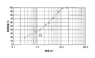
- FIG. 5 is a diagram showing the relationship of the cumulative mass to the particle size of coal.
- the horizontal axis of FIG. 5 represents the particle size (mm) of coal, and the vertical axis represents the cumulative mass (%) of coal.
- the mass of coal having a particle size of 1.7 mm or less is 40.9% with respect to the mass of all coal.
- the relational expression of the cumulative mass with respect to each particle size was obtained as an approximate curve L1. From this approximate curve L1, it was found that the particle size for a cumulative mass of 50% was 2.1 mm.
- FIG. 6 the relationship of the adhesive force with respect to the water
- the adhesion force was measured based on the Jenikecel method described in Japan Powder Industry Technical Association Standard, SAP 15-13: 2013, Powder Single-Shear Test Method. It was found that when the moisture content changes from 55% by mass to 60% by mass, the adhesion of LY charcoal increases rapidly.
- the size of the dispersion plate 61 is 180 mm ⁇ 110 mm.
- ⁇ 7 mm communication holes are formed at a pitch of 21 mm.
- the aperture ratio of the dispersion plate 61 is 8.74%.
- three temperature sensors 66, 67 and 68 were attached to the drying chamber 51 from the bottom to the top.
- the lower temperature sensor 66 is attached at a height corresponding to the coal discharge pipe 53.
- the middle temperature sensor 67 is attached to a height corresponding to the lower end portion of the observation window 54.
- the upper temperature sensor 68 is attached at a height corresponding to an intermediate portion between the coal supply pipe 55 and the steam pipe 39.
- water vapor was used as the drying gas W6 supplied to the drying chamber 51, and the temperature of the water vapor was set to 70 ° C.
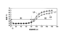
- FIG. 6 shows the detection results of the temperature sensors 66, 67 and 68 with respect to the elapsed time after fluidizing 2 kg of LY charcoal.
- a dotted line L6 represents a detection result by the lower temperature sensor 66.
- a two-dot chain line L7 represents a detection result by the middle temperature sensor 67
- a solid line L8 represents a detection result by the upper temperature sensor 68.
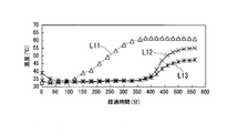
- FIG. 8 shows the detection results of the temperature sensors 66, 67, 68 with respect to the elapsed time since the drying gas W6 was supplied.
- the horizontal axis of FIG. 8 represents the elapsed time (minutes) after supplying the drying gas W6, and the vertical axis represents the temperature (° C.) of the detection results of the temperature sensors 66, 67, 68.
- FIG. 8 shows the detection results of the temperature sensors 66, 67, 68 with respect to the elapsed time since the drying gas W6 was supplied.
- the horizontal axis of FIG. 8 represents the elapsed time (minutes) after supplying the drying gas W6, and the vertical axis represents the temperature (° C.) of the detection results of the temperature sensors 66, 67, 68.
- the flow rate of the drying gas W6 is 150 Nm 3 / h, and the flow velocity on the dispersion plate 61 is 2.1 m / s.
- a dotted line L11 represents a detection result by the lower temperature sensor 66.
- a two-dot chain line L12 represents a detection result by the middle temperature sensor 67
- a solid line L13 represents a detection result by the upper temperature sensor 68.
- LY charcoal having a moisture content of 63% has a relatively strong adhesion. For this reason, it has been found that even when the drying gas W6 is supplied, LY charcoal accumulates on the dispersion plate 61 and closes the communication holes of the dispersion plate 61. As a result, it was found that the temperature detected by the temperature sensors 67 and 68 was lower than that of the lower temperature sensor 66, and LY charcoal was not fluidized. Further, the experiment was conducted by increasing the flow rate of the drying gas W6 to 5.0 m / s, but it was found that the LY charcoal remained deposited on the dispersion plate 61 and did not fluidize.
- the drying device 3 of the present embodiment includes a sieving classifier (classifying unit) 71 and a classified coal flow rate adjusting unit 72 in addition to the components of the drying device 1 of the first embodiment.
- the sieving classifier 71 classifies the dry coal W1 dried in the drying chamber 11 based on the particle size (particle diameter) of the dry coal W1.
- the sieving and classifying device 71 is provided at a connection portion between the product conveying pipe 36 and the return pipe 21.
- the sieving classifier 71 supplies only dry large-diameter coal (pre-dried large-diameter material) W10 having a particle size equal to or larger than a reference value out of the dry coal W1 to the return pipe 21.
- the reference value is 1 mm or the like at d50 (median diameter).
- the reference value can be adjusted by selecting the size of the sieve mesh.
- the sieving classifier 71 supplies only the dry small-diameter coal W11 having a particle size less than the reference value among the dry coal W1 to the cooling device 37.
- those having a larger particle size than those having a smaller particle size contain a larger proportion of moisture.
- the ratio of the dry large diameter coal W10 with respect to the coal which the sieving classifier 71 supplies to the return pipe 21 is not limited to 100%. That is, the coal supplied to the return pipe 21 by the sieving classifier 71 is basically composed of the dry large-diameter coal W10, but the coal may contain the dry small-diameter coal W11.
- the classified coal flow rate control unit 72 supplies only the amount of the reference ratio of the dry large-diameter coal W10 to the drying chamber 11 through the return pipe 21.
- the classified coal flow rate adjustment unit 72 is provided in an intermediate portion of the return pipe 21.
- a first end portion of the second connecting pipe 73 is connected to the classified coal flow rate adjusting unit 72.
- a second end of the second connection pipe 73 is connected to an intermediate part of the connection pipe 41.
- the classified coal flow rate adjustment unit 72 adjusts the amount of the reference ratio by a valve (not shown) that adjusts the opening degree of the return pipe 21 and a valve (not shown) that adjusts the opening degree of the second connection pipe 73. Can do.
- the amount of the reference ratio is appropriately set depending on the material balance of the coal W3 supplied to the drying chamber 11, the dry large-diameter coal W10, the dry coal W1 obtained in the drying chamber 11, and the like.
- the classified coal flow rate adjustment unit 72 supplies the second connecting pipe 73 with an amount other than the reference ratio in the dry large-diameter coal W10 supplied to the classified coal flow rate adjustment unit 72 via the return pipe 21.
- the 2nd end part of the 2nd connection piping 73 may be connected between the part in which the sieving classifier 71 in the product conveyance piping 36 was provided, and the 2nd end part.
- the reference ratio is, for example, 10 to 20%.
- the reference ratio can be adjusted on a trial and error basis while confirming that the mixture of coal W3 and dry large-diameter coal W10 (hereinafter referred to as mixed coal) adheres in the drying chamber 11.
- the reference ratio can be appropriately set by evaluating the angle of repose of the mixed coal (the maximum angle at which the slope on which the mixed coal is loaded is stable without collapsing). For example, Carr, RL “Evaluating flow properties of solids” Chem. Eng. 1965; 72: p.163-168 is known. According to this angle of repose, the degree of fluidity is classified into seven levels, such as extremely good, good,..., Slightly poor, poor, and extremely poor.
- the angle of repose at which the degree of fluidity is extremely good to slightly poor is 0 ° or more and 55 ° or less.
- the dry coal W ⁇ b> 1 obtained in the third chamber 16 of the drying chamber 11 is conveyed through the product conveying pipe 36 and supplied to the sieving classifier 71.
- the sieving classifier 71 supplies only the dry large-diameter coal W10 out of the dry coal W1 to the classification coal flow rate adjusting unit 72 on the downstream side of the return pipe 21, and supplies only the dry small-diameter coal W11 to the cooling device 37.
- the classified coal flow rate adjusting unit 72 supplies only the amount of the reference ratio of the dry large-diameter coal W10 supplied from the sieving classifier 71 into the first chamber 12 of the drying chamber 11 via the return pipe 21.
- the classified coal flow rate adjusting unit 72 supplies the second connecting pipe 73 with an amount other than the reference ratio in the dry large-diameter coal W10.
- the dry large-diameter coal W10 supplied to the second connection pipe 73 is collected into the powder of the coal W3 collected by the dust collector 40 and flowing in the connection pipe 41, and the dry small-diameter coal W11 classified by the sieving classifier 71. Merge and become product coal W7.
- the dry large-diameter coal W10 in the amount of the reference ratio supplied into the first chamber 12 is further fluidized in the first chamber 12 and dried to become fluidized coal W2.
- the dry large-diameter coal W10 has a higher moisture content than the dry small-diameter coal W11. For this reason, due to the heat of vaporization of water in the coal, the temperature is less likely to rise when the dry large-diameter coal W10 is heated than when the dry small-diameter coal W11 is heated.
- the amount of dry large-diameter coal W10 supplied into the first chamber 12 is adjusted by the classified coal flow rate adjusting unit 72, so that the recycle amount increases and the production amount of the product coal W7 decreases. While being able to suppress, the temperature of dry large diameter coal W10 etc. which are heated in the drying chamber 11 is adjusted more effectively.
- the drying apparatus 1 of the first embodiment since the dried coal W1 dried in the drying chamber 11 is returned to the drying chamber 11, a part of the dried coal W1 may be dried many times in the drying chamber 11.
- the drying device 3 according to the present embodiment includes the sieving and classifying device 71, whereby the dried coal is suppressed from returning to the drying chamber 11.
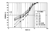
- FIG. 11 shows the change in the cumulative proportion of coal with respect to the particle size in the proportion of moisture in the coal.
- the horizontal axis in FIG. 11 represents the particle size of coal, and the vertical axis represents the cumulative proportion of coal. From FIG. 11, the average particle diameter (intersection with the line L16 representing d50) at each moisture ratio was determined.
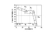
- FIG. 12 shows the change in average particle diameter with respect to the water content of coal.
- the horizontal axis of FIG. 12 represents the moisture content of coal, and the vertical axis represents the average particle diameter of coal.
- the range R a representing the state of bulk water described above.
- a range R b representing the state of capillary condensed water
- a range R c representing the state of multilayer water
- a range R d representing the state of single layer water are shown.
- the water content is in the range of 30 to 60%, and the average particle size is approximately constant at 1.8 to 2.0 mm even when the water content is reduced.
- R 7 The scope proportion of water is less than the area R 7, there is a region R 8 having an average particle size in accordance with the proportion of water is reduced is reduced.
- the average particle size decreases without increasing as the proportion of moisture in the coal decreases.
- the average particle diameter of coal with a water content of 20% is about 1.5 mm.
- 1.5 mm is used as the reference value of the particle size classified by the sieving classifier 71, about 50% of dry coal having a moisture content of 20% or less can be removed.
- FIG. 13 the change of 0.6 mm or less sieving mass (weight) ratio with respect to the ratio of the water
- the mass ratio under 0.6 mm or less referred to here means the ratio of the mass of coal that has passed through the sieve with an outer diameter of 0.6 mm or less with respect to the total mass of the sieved coal.
- the horizontal axis of FIG. 13 represents the moisture content of coal, and the vertical axis represents the mass ratio below 0.6 mm.
- the above-mentioned ranges R a to R d are shown. From coal after hydrolysis to coal ratio of water of about 55%, there is a region R 10 of 0.6mm or less undersize mass ratio in accordance with the proportion of water is reduced increases.
- the scope proportion of water is less than the region R 10, there is a substantially constant regions R 11 0.6 mm or less undersize mass ratio be the percentage of moisture is low, about 30%.
- the scope proportion of water is less than the region R 11, there is a region R 12 where under 0.6mm below the sieve mass ratio in accordance with the proportion of water is reduced increases. As explained above, as the water content in the coal decreases, the mass ratio under 0.6 mm or less increases without decreasing.
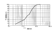
- FIG. 14 the experimental result at the time of using the brown coal whose ratio of a moisture is 60% is shown.
- the horizontal axis of FIG. 14 represents the particle size of lignite, and the vertical axis represents the cumulative ratio of lignite. Circles in the figure represent individual experimental results. For example, the cumulative proportion of lignite with a particle size of 1.4 mm is 27%.
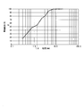
- FIG. 15 shows the experimental results in the case of using lignite that has been dried until the average water content reaches 20%.
- the horizontal axis of FIG. 15 is the same as FIG.
- the cumulative proportion of lignite with a particle size of 1.4 mm is 54%. That is, when the lignite is compared before and after drying, the particle size of the lignite becomes small when the moisture content in the lignite is small.
- Table 1 shows the results of determining the ratio of the particle diameter of 1.5 mm or more and the average particle diameter in the lignite with a moisture ratio of 60% and the lignite dried to an average moisture ratio of 20%.
- the “average moisture ratio” is described as follows. In the lignite dried until the average moisture ratio becomes 20% as described later, the moisture ratio is further set for each particle size range. This is because it was requested.
- the particle size of 1.5 mm or less was 27.7%, and the average particle size (d50) was 2.7 mm.
- the particle size of 1.5 mm or less was 54.9%, and the average particle size (d50) was 1.1 mm.
- the average particle size was reduced to a value of about 41% (1.1 / 2.7) by decreasing the water content.
- the results of the determination of the moisture content in the lignite with a particle size of 1.5 mm or less and the lignite with a particle size of 5.0 mm or more are shown. It is shown in 2.
- the ratio of moisture was 17.6%, and in the lignite having a particle diameter of 5.0 mm or more, the ratio of moisture was 24.0%.
- the proportion of moisture contained in the one having a larger particle size is larger than the proportion of moisture contained in the one having a smaller particle size.
- the ratio of the particle size of 1.5 mm or less is 54.9%.
- the drying device 3 includes a sieving classifier 71.
- the inventors have found that among the dry coals W1, those having a larger particle size than those having a smaller particle size contain a higher proportion of moisture.
- the drying device 3 includes a classified coal flow rate adjusting unit 72. Thereby, while adjusting the ratio made into fluidized coal W2 among dry large diameter coal W10, it can suppress that the amount of recycle increases too much and the production amount of product coal W7 falls, and dry large diameter coal W10. Etc. can be adjusted more effectively.
- the classification unit is the sieving classifier 71.
- the classifying unit is not limited to this, and may be a dry classifier such as a cyclone or a fluidized bed.
- the drying device 3 may not include the classified coal flow rate adjustment unit 72.
- the first to third embodiments of the present invention have been described in detail with reference to the drawings. However, the specific configuration is not limited to this embodiment, and the configuration does not depart from the gist of the present invention. Changes, combinations, deletions, etc. are also included. Furthermore, it goes without saying that the configurations shown in the embodiments can be used in appropriate combinations.
- the object to be dried is coal, but the object to be dried is not limited to this, and may be sludge or the like.
Landscapes
- Engineering & Computer Science (AREA)
- Mechanical Engineering (AREA)
- General Engineering & Computer Science (AREA)
- Life Sciences & Earth Sciences (AREA)
- Microbiology (AREA)
- Chemical & Material Sciences (AREA)
- Combustion & Propulsion (AREA)
- Drying Of Solid Materials (AREA)
Abstract
Description
しかしながらこの方法では、パージガスを乾燥室の多くの個所に導入する必要があり、設備コスト及び運用コストが増加する問題がある。
一方で、乾燥室内では、褐炭に流動化蒸気が導入されることで、褐炭が流動され流動層を形成する。さらに、乾燥室内に設けられた伝熱部材により褐炭が乾燥する。乾燥した褐炭は製品石炭となりボイラー等の原料として用いられる。なお、乾燥した褐炭の一部は、前述の乾燥物として、乾燥室に供給される。
(1)本発明の乾燥方法は、少なくとも流動化室と混合室とを有する乾燥装置における、水分を含有する被乾燥物を乾燥させる乾燥方法であって、
前記被乾燥物を予め乾燥させて得られた予乾燥物を、前記流動化室内に供給した状態で、さらに流動化させて流動化予乾燥物にし、
前記流動化室とは仕切りにより区画されるとともに前記仕切りの下部に形成された貫通孔を通して互いに連通する前記混合室内に前記流動化予乾燥物を移動させた状態で、前記流動化予乾燥物に、前記貫通孔よりも上方から前記被乾燥物を混合することを特徴としている。
流動化室と、前記流動化室とは仕切りにより区画されるとともに前記仕切りの下部に形成された貫通孔を通して互いに連通する混合室と、を少なくとも有する乾燥室と、
前記被乾燥物を予め乾燥させて得られた予乾燥物を前記流動化室内に供給する予乾燥物供給部と、
前記乾燥室内に供給された前記予乾燥物を、前記流動化室内でさらに流動化させて流動化予乾燥物とする流動化部と、
前記流動化室内から前記貫通孔を通して前記混合室に移動した前記流動化予乾燥物に、前記貫通孔よりも上方から前記被乾燥物を混合する被乾燥物供給部とを備えることを特徴としている。
(4)上記の乾燥装置において、前記流動化部は、前記乾燥室内に供給された前記予乾燥物に下方から上方に向けて流れる乾燥用ガスを供給することで、前記予乾燥物を流動化させてもよい。
これらの発明によれば、予乾燥物は自重により乾燥室等の下部に付着する場合がある。予乾燥物に下方から上方に向けて流れる乾燥用ガスを供給することで、乾燥室等の下部に付着した被乾燥物に対して上方に向けた外力を作用させる。
(6)上記の乾燥装置において、前記被乾燥物供給部は、前記流動化予乾燥物に上方又は側方から前記被乾燥物を混合してもよい。
これらの発明によれば、予乾燥物に乾燥用ガスを供給する方向と、流動化予乾燥物に被乾燥物を混合する方向とが異なる。
(8)上記の乾燥装置において、前記乾燥室は、前記混合室とは第2仕切りにより区画されるとともに前記第2仕切りに形成された第2貫通孔を通して互いに連通する第3室を有し、前記予乾燥物供給部の端部は、前記第3室の側板に接続されていてもよい。
これらの発明によれば、流動化室内で流動化予乾燥物をより確実に流動化させた状態で、混合室において流動化予乾燥物に被乾燥物を混合する。
発明者らは、予乾燥物のうちで、粒径が小さいものよりも粒径が大きいものの方が含有する水分の割合が多いことを見出した。含有する水分の割合が少ないと、予乾燥物が加熱されたときに予乾燥物の温度が上がりやすくなる。
(11)上記の乾燥装置は、前記乾燥室で乾燥された前記予乾燥物を粒径に基づいて分級し、前記予乾燥物のうち前記粒径が基準値以上の予乾燥大径物を前記予乾燥物供給部に供給する分級部を備えていてもよい。
(12)上記の乾燥装置において、前記分級部は篩い分け分級機であってもよい。
(13)上記の乾燥装置は、前記予乾燥大径物のうち基準割合の量を前記予乾燥物供給部に供給する分級炭流量調節部を備えていてもよい。
上記(3)に記載の乾燥方法、及び上記(4)に記載の乾燥装置によれば、予乾燥物を効率的に流動化させることができる。
上記(5)に記載の乾燥方法、及び上記(6)に記載の乾燥装置によれば、予乾燥物に供給する乾燥用ガスに対して、流動化予乾燥物に混合する被乾燥物が支障になりにくくすることができる。
上記(9)及び(10)に記載の乾燥方法によれば、予乾燥大径物中の水分の割合が少なくなって予乾燥大径物等の温度が高くなり過ぎるのを抑制することができる。
上記(11)から(13)に記載の乾燥装置によれば、予乾燥大径物のうち流動化予乾燥物にする割合を調節し、予乾燥大径物等の温度をより効果的に調節することができる。
以下、本発明に係る乾燥装置の第1実施形態を、図1から図3を参照しながら説明する。本乾燥装置は、褐炭等の水分の含有割合が高い石炭(被乾燥物)を連続式に乾燥させるためのものである。
図1に示すように、本実施形態の乾燥装置1は、乾燥室11と、石炭を予め乾燥させて得られた乾燥石炭(予乾燥物)W1を乾燥室11に供給する戻り配管(予乾燥物供給部)21と、乾燥室11内に供給された乾燥石炭W1を、さらに流動化させつつ乾燥させて流動化石炭(流動化予乾燥物)W2とする流動化部26と、流動化石炭W2に石炭W3を混合する供給ホッパ(被乾燥物供給部)31と、を備えている。
乾燥用ガス発生装置27には、ボイラー等の公知の装置を用いることができる。なお、乾燥用ガス発生装置27として、後述する冷却装置37等に設けた熱交換器等を用いてもよい。この熱交換器内の冷却水により乾燥石炭W1を冷却することで、冷却水が加熱されて乾燥用ガスW6を得ることができる。
乾燥用ガス室28の天板は、前述の分散板17である。本実施形態では、乾燥用ガス室28が、各室12、14、16に対応して3室に分割されている例を示している。乾燥用ガス室28は、分散板17の各連通孔17aを通して各室12、14、16と連通している。
第3室16における第2室14とは反対側の側板には、製品搬送配管36の第一端部が接続されている。製品搬送配管36の第二端部は、冷却装置37に接続されている。第3室16の天板には、蒸気配管39の第一端部が接続されている。蒸気配管39の第二端部は、集塵装置40に接続されている。
集塵装置40には、連結配管41の第一端部が接続されている。連結配管41の第二端部は、製品搬送配管36の中間部に接続されている。
後述するように、石炭W3を予め乾燥させて乾燥石炭W1を得ておく。戻り配管21は、第1室12内に乾燥石炭W1を供給する。
流動化部26の乾燥用ガス発生装置27は、乾燥用ガスW6を発生させる。この乾燥用ガスW6は乾燥用ガス室28に供給され、分散板17の各連通孔17aを通して乾燥室11の各室12、14、16に供給される。
乾燥石炭W1は自重により第1室12等の下部の分散板17等に付着する場合がある。乾燥石炭W1に下方から上方に向けて流れる乾燥用ガスW6を供給することで、分散板17に付着した石炭W3に対して上方に向けた外力を作用させる。
乾燥用ガスW6は、第1室12内だけでなく、第2室14及び第3室16内に下方から上方に向けて流れるように供給される。
これに対して、乾燥石炭W1が乾燥用ガスW6により流動化されないと、図3に示すように、乾燥石炭W1は、第1室12内で流れ動かないで、乾燥石炭W1の自重や乾燥石炭W1の付着力等により分散板17等に付着する。
このように、流動化部26は、第1室12内に供給された乾燥石炭W1に下方から上方に向けて流れる乾燥用ガスW6を供給することで、第1室12内で乾燥石炭W1を流動化する。乾燥石炭W1を第1室12内に供給した状態で、乾燥石炭W1を流動化石炭W2にする。
流動化石炭W2は、石炭W3を予め乾燥させるとともに、さらに流動化させつつ乾燥させたものである。このため、第2室14内でこの流動化石炭W2に石炭W3を混合することで、石炭W3が効率的に流動化し、流動化した状態の石炭W3が乾燥する。乾燥装置1では、乾燥石炭W1に乾燥用ガスW6を供給する方向である下方から上方に向かう方向と、流動化石炭W2に石炭W3を供給する方向である上方から下方に向かう方向とが異なる。乾燥室11が第1室12、仕切り13、及び第2室14を備えることで、第1室12内で流動化石炭W2をより確実に流動化させた状態で、第2室14において流動化石炭W2に石炭W3を混合する。
なお、流動化石炭W2は第2室14内で、乾燥用ガスW6によりさらに流動化しつつ乾燥する。
冷却装置37には、例えば図示しない熱交換器が設けられている。乾燥石炭W1は、この熱交換器により冷却される。熱交換器内に冷却水を収容しておいてもよい。
冷却装置37で冷却された乾燥石炭W1は、冷却装置37から搬送され、製品石炭W7としてボイラー等の原料として用いられる。
一方で、乾燥された流動化石炭W2及び石炭W3から得られた湿潤ガスW8は、第3室16の上部から排出される。この湿潤ガスW8は、水蒸気に、乾燥させた石炭W3の粉末が含まれたものである。湿潤ガスW8は、集塵装置40で石炭W3の粉末が回収される。 回収された石炭W3の粉末は、連結配管41及び製品搬送配管36を通して冷却装置37に供給され、製品石炭W7となる。一方で、集塵装置40で処理された湿潤ガスW8は、外部に排出される。
乾燥石炭W1に下方から上方に向けて流れる乾燥用ガスW6を供給して、乾燥石炭W1を流動化する。乾燥石炭W1は、自重により乾燥室11の下部に付着する場合がある。乾燥石炭W1に下方から上方に向けて流れる乾燥用ガスW6を供給することで、乾燥室11の下部に付着した乾燥石炭W1に対して上方に向けた外力を作用させる。これにより、乾燥石炭W1を効率的に流動化させることができる。
乾燥室11は第1室12、仕切り13、及び第2室14を備えるため、第1室12内で流動化石炭W2をより確実に流動化させた状態で、第2室14において流動化石炭W2に石炭W3を混合する。このため、石炭W3をより確実に流動化させることができる。
乾燥室11は、第1室12、第2室14、及び第3室16の3つの室を有するとした。しかし、乾燥室11が有する室の数はこの限りではなく、2つでもよいし、4つ以上でもよい。
次に、本発明の第2実施形態について図4から図8を参照しながら説明するが、前記実施形態と同一の部位には同一の符号を付してその説明は省略し、異なる点についてのみ説明する。本実施形態の乾燥装置は、石炭W3をバッチ式に乾燥させるためのものである。 図4に示すように、本実施形態の乾燥装置2は、角筒状に形成された乾燥室51を有している。乾燥室51は、その軸線が上下方向に延びるように配置されている。
乾燥室51には、下方から上方に向かって、石炭排出管53、のぞき窓54、石炭供給管(予乾燥物供給部、被乾燥物供給部)55、及び蒸気配管39がこの順に設けられている。石炭排出管53は、乾燥室51内で製造された乾燥石炭W1を外部に取り出すための配管である。のぞき窓54は、乾燥室51内を目視により確認するための窓である。石炭供給管55は、乾燥室51内に乾燥石炭W1及び石炭W3を供給するための配管である。 乾燥室51の上端部の開口は、蓋部材56により封止されている。
まず、石炭供給管55を通して乾燥室51内に乾燥石炭W1を供給する。分散板61上に張り込まれた(配置された)乾燥石炭W1の量は、のぞき窓54を通して確認することができる。
次に、流動化部63により乾燥石炭W1に下方から乾燥用ガスW6を供給する。乾燥用ガスW6は、分散板61に形成された図示しない連通孔を通して上方に向かって流れる。これにより、乾燥室51内の乾燥石炭W1が流動化しつつ乾燥し、流動化石炭W2(不図示)となる。流動化石炭W2が流動化している状態は、のぞき窓54を通して確認することができる。
乾燥石炭W1は、石炭排出管53から外部に取り出される。
以下では、本発明の実施例及び比較例を具体的に示してより詳細に説明するが、本発明は以下の実施例に限定されるものではない。
まず、乾燥装置2で乾燥させる石炭として用いたLY炭について説明する。LY炭は、Loy Yangで採取された褐炭であり、本実施形態では、LY炭を粉砕した状態で用いている。図5は、石炭の粒径に対する累積質量の関係を表す図である。図5の横軸は石炭の粒径(mm)を表し、縦軸は石炭の累積質量(%)を表す。例えば、この石炭において、粒径が1.7mm以下の石炭の質量は、全石炭の質量に対して40.9%である。 各粒径に対する累積質量の関係式を、近似曲線L1として求めた。この近似曲線L1から、累積質量50%に対する粒径は、2.1mmであることが分かった。
水分の含有量が55質量%から60質量%に変化する際に、LY炭の付着力が急激に強くなることが分かった。
実験を行うにあたり、図4に示すように、乾燥室51に下方から上方に向かって、3つの温度センサ66、67、68を取付けた。下部温度センサ66は、石炭排出管53に対応する高さに取付けられている。中部温度センサ67は、のぞき窓54の下端部に対応する高さに取付けられている。上部温度センサ68は、石炭供給管55と蒸気配管39との中間部に対応する高さに取付けられている。
なお、乾燥室51に供給する乾燥用ガスW6として水蒸気を用い、水蒸気の温度を70℃とした。
流量150Nm3/h(ノルマル立方メートル毎時)、分散板61上における流速が2.1m/s(メートル毎秒)の乾燥用ガスW6で、水分の含有率が55%のLY炭2kgを予め流動化させつつ乾燥させた。なお、図6に示すように、水分の含有率が55%のLY炭の付着力は、2g/cm3程度である。2kgのLY炭は、流動化して流動化石炭W2となった。
図7に、2kgのLY炭を流動化させてからの経過時間に対する温度センサ66、67、68の検出結果を示す。図7の横軸はLY炭を流動化させてからの経過時間(分)を表し、縦軸は温度センサ66、67、68の検出結果の温度(℃)を表す。点線L6が、下部温度センサ66による検出結果を表す。同様に、二点鎖線L7が中部温度センサ67による検出結果を表し、実線L8が上部温度センサ68による検出結果を表す。
経過時間が0分から80分頃までの恒温乾燥区間R1では、温度センサ66、67、68は35℃程度を維持している。80分頃以降の減率乾燥区間R2では、温度センサ66、67、68で検出される温度が徐々に上昇している。検出される温度は、温度が高い順に、下部温度センサ66、中部温度センサ67、上部温度センサ68となることが分かった。
初期に供給した2kgのLY炭、及び追加して供給した4kgのLY炭は、恒温乾燥区間R1及び減率乾燥区間R2のいずれにおいても、流動化していることが分かった。LY炭が流動化していることは、のぞき窓54を通して目視によっても確認した。
この結果、乾燥室51内でLY炭が安定して流動化し、乾燥室51内にLY炭が付着しないことが分かった。
水分の含有率が63%のLY炭6kgを、分散板61上に装填した。流動化部63によりLY炭に下方から乾燥用ガスW6を供給し、LY炭の流動化を試みた。図8に、乾燥用ガスW6を供給してからの経過時間に対する温度センサ66、67、68の検出結果を示す。図8の横軸は乾燥用ガスW6を供給してからの経過時間(分)を表し、縦軸は温度センサ66、67、68の検出結果の温度(℃)を表す。
図8の例では、乾燥用ガスW6の流量を150Nm3/h、分散板61上における流速を2.1m/sとした。点線L11が、下部温度センサ66による検出結果を表す。同様に、二点鎖線L12が中部温度センサ67による検出結果を表し、実線L13が上部温度センサ68による検出結果を表す。
さらに、乾燥用ガスW6の流速を5.0m/sまで増加させて実験を行ったが、LY炭は分散板61に堆積したままで、流動化しないことが分かった。
次に、本発明の第3実施形態について図9から図15を参照しながら説明するが、前記実施形態と同一の部位には同一の符号を付してその説明は省略し、異なる点についてのみ説明する。
図9に示すように、本実施形態の乾燥装置3は、第1実施形態の乾燥装置1の各構成に加えて、篩い分け分級機(分級部)71及び分級炭流量調節部72を備える。
篩い分け分級機71は、乾燥室11で乾燥された乾燥石炭W1を乾燥石炭W1の粒径(粒子径)に基づいて分級する。篩い分け分級機71は、製品搬送配管36と戻り配管21との接続部に設けられている。篩い分け分級機71は、乾燥石炭W1のうち粒径が基準値以上の乾燥大径石炭(予乾燥大径物)W10だけを戻り配管21に供給する。例えば、基準値は、d50(メジアン径)で1mm等である。例えば、篩い分け分級機71では、篩目の大きさを選ぶことで基準値を調節することができる。
なお、篩い分け分級機71が戻り配管21に供給する石炭に対する乾燥大径石炭W10の割合は、100%に限定されない。すなわち、篩い分け分級機71が戻り配管21に供給する石炭は、基本的に乾燥大径石炭W10で構成されているが、その石炭中に乾燥小径石炭W11が含まれていてもよい。
分級炭流量調節部72は、戻り配管21を介して分級炭流量調節部72に供給された乾燥大径石炭W10のうち基準割合以外の量を第2連結配管73に供給する。
なお、第2連結配管73の第二端部は、製品搬送配管36における篩い分け分級機71が設けられた部分と第二端部との間に接続されてもよい。
石炭W3と乾燥大径石炭W10とを混合したもの(以下、混合石炭と言う)が乾燥室11内に付着する状況を確認しながら、前記基準割合を試行錯誤的に調整することもできる。しかし、例えば、混合石炭の安息角(混合石炭を積んだ斜面が崩れ落ちないで安定している最大角)を評価することで、基準割合を適正に設定することができる。
例えば、Carrによる流動特性と対応する安息角の分類(Carr,R.L. “Evaluating flow properties of solids” Chem. Eng. 1965; 72:p.163-168)が知られている。この分類は、安息角に対応して、流動性の程度を、極めて良好、良好、‥、やや不良、不良、極めて不良、というように7段階に分類している。この分類において、流動性の程度が極めて良好からやや不良までとなる安息角が、0°以上55°以下となる。
混合石炭の安息角が0°以上55°以下となるように基準割合を調整することで、混合石炭の流動性を高め、混合石炭が乾燥室11内に付着するのを抑制することができる。
・日本エネルギー学会編「石炭の科学と技術 ~未来につなぐエネルギー~」、コロナ社・D.J. Allardice “The Water in Brown Coal Chapter 3”
石炭粒子W15中の水分の割合が40%未満程度になると、隙間S1中の水Vが蒸発し、後述する隙間S2中、及び位置S3、S4の水Vが残る。
(b)の含有水が毛細管凝縮水の状態では、石炭粒子W15に形成された毛細管W16内の隙間S2に凝縮した水Vが存在する。この状態での石炭粒子W15中の水分の割合は、15~40%程度である。
石炭粒子W15中の水分の割合が15%未満程度になると、隙間S2中の水Vが蒸発し、後述する位置S3、S4の水Vが残る。
石炭粒子W15中の水分が7%未満程度になると、位置S3の水Vが蒸発し、後述する位置S4の水Vが残る。
(d)の含有水が単層水の状態では、石炭粒子W15の表面における含酸素官能基W18と、単層吸着により保持されている位置S4の水Vが存在する。この状態での石炭粒子W15中の水分の割合は、7%未満程度である。なお、(d)の状態におけるイメージは、例えば(c)の状態において、石炭粒子W15の表面と弱い水素結合により保持されている水Vとの境界である範囲R4を拡大したものである。
乾燥室11の第3室16内で得られた乾燥石炭W1は、製品搬送配管36を通して搬送され、篩い分け分級機71に供給される。篩い分け分級機71は、乾燥石炭W1のうち、乾燥大径石炭W10だけを戻り配管21の下流側の分級炭流量調節部72に供給し、乾燥小径石炭W11だけを冷却装置37に供給する。
分級炭流量調節部72は、篩い分け分級機71から供給された乾燥大径石炭W10のうち基準割合の量だけを戻り配管21を介して乾燥室11の第1室12内に供給する。
分級炭流量調節部72は、乾燥大径石炭W10のうち基準割合以外の量を第2連結配管73に供給する。第2連結
配管73に供給された乾燥大径石炭W10は、集塵装置40で回収され連結配管41内を流れる石炭W3の粉末、及び、篩い分け分級機71で分級された乾燥小径石炭W11に合流し、製品石炭W7となる。
実験室レベルの試験(ラボ試験)では、石炭には褐炭であるLY炭を用いた。石炭の初期の水分の割合は、60%である。石炭の粒度分布の測定と、温度107℃の恒温槽によるこの石炭の乾燥と、を交互に繰り返した。乾燥後の石炭中の水分の割合は、55%、45%、35%、30%、18%、及び7%の順で低下した。また、初期の水分の割合が60%である石炭に加水することで、石炭の水分の割合を64%にしたサンプルも作成した。
加水後の石炭から初期の石炭まで水分の割合が少なくなるにしたがい平均粒径が小さくなる領域R6がある。領域R6よりも水分の割合が少ない範囲には、水分の割合が30~60%の範囲で、水分の割合が少なくなっても平均粒径が1.8~2.0mmとほぼ一定の領域R7がある。領域R7よりも水分の割合が少ない範囲には、水分の割合が少なくなるにしたがい平均粒径が小さくなる領域R8がある。
図12から、水分の割合が20%の石炭の平均粒径が約1.5mmである。例えば、篩い分け分級機71で分級する粒径の基準値として1.5mmを用いると、水分の割合が20%以下の乾燥した石炭を約50%除去することができる。
加水後の石炭から水分の割合が55%程度の石炭まで、水分の割合が少なくなるにしたがい0.6mm以下篩下質量比が大きくなる領域R10がある。領域R10よりも水分の割合が少ない範囲には、水分の割合が少なくなっても0.6mm以下篩下質量比が約30%とほぼ一定の領域R11がある。領域R11よりも水分の割合が少ない範囲には、水分の割合が少なくなるにしたがい0.6mm以下篩下質量比が大きくなる領域R12がある。
以上説明したように、石炭中の水分の割合が少なくなるにしたがい、0.6mm以下篩下質量比は小さくなることなく大きくなる。
1時間当たりに500kgの石炭を処理できるベンチプラント試験装置である乾燥装置を用いて、試験を行った。初期の水分の割合が60%である褐炭を、平均の水分の割合が20%になるまで乾燥させ、粒度分布を測定した。
図14に、水分の割合が60%の褐炭を用いた場合の実験結果を示す。図14の横軸は褐炭の粒径を表し、縦軸は褐炭の累積割合を表す。図中の○印が、個々の実験結果を表す。例えば、粒径が1.4mmの褐炭の累積割合は27%である。
すなわち、褐炭を乾燥させた前後で比べた場合に、褐炭中の水分の割合が少ないと褐炭の粒径が小さくなる。
ここで表1において「平均の水分の割合」と記載したのは、後述するように平均の水分の割合が20%になるまで乾燥させた褐炭において、さらに粒径の範囲ごとに水分の割合を求めたためである。

このように、褐炭を乾燥させると粒径が小さい割合が多くなり、平均粒径が小さくなる。
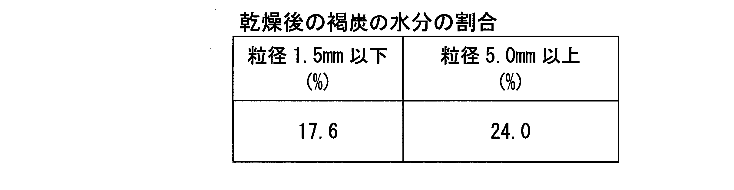
このように、同一の褐炭内においても、粒径が小さいものが含有する水分の割合よりも粒径が大きいものの方が含有する水分の割合が多い。
例えば、平均の水分の割合が20%になるまで乾燥させた褐炭では、粒径が1.5mm以下の割合が54.9%である。平均の水分の割合が20%になるまで乾燥させた褐炭を1.5mmの篩目を用いて分級して篩上に残った褐炭を用いると、約55%の水分の割合が20%以下まで乾燥させた褐炭を除去することができる。
さらに、乾燥装置3は篩い分け分級機71を備える。発明者らは、乾燥石炭W1のうちで、粒径が小さいものよりも粒径が大きいものの方が含有する水分の割合が多いことを見出した。含有する水分の割合が少ないと、乾燥石炭W1が加熱されたときに乾燥石炭W1の温度が上がりやすくなる。したがって、乾燥大径石炭W10中の水分の割合が少なくなって乾燥大径石炭W10等の温度が高くなり過ぎるのを抑制することができる。
乾燥装置3は分級炭流量調節部72を備える。これにより、乾燥大径石炭W10のうち流動化石炭W2にする割合を調節し、リサイクル量が多くなり過ぎて製品石炭W7の生産量が低下することを抑えることができるとともに、乾燥大径石炭W10等の温度をより効果的に調節することができる。
乾燥大径石炭W10の量が多くない場合等には、乾燥装置3は分級炭流量調節部72を備えなくてもよい。
例えば、前記第1実施形態から第3実施形態では、被乾燥物は石炭であるとしたが、被乾燥物はこれに限定されず、汚泥等でもよい。
11、51 乾燥室
12 第1室(流動化室)
13、15 仕切り
13a、15a 貫通孔
14 第2室(混合室)
16 第3室
17 分散板
17a 連通孔
21 戻り配管(予乾燥物供給部)
27 乾燥用ガス発生装置
28 乾燥用ガス室
26、63 流動化部
31 供給ホッパ(被乾燥物供給部)
36 製品搬送配管
37 冷却装置
39 蒸気配管
40 集塵装置
71 篩い分け分級機(分級部)
72 分級炭流量調節部
W1 乾燥石炭(予乾燥物)
W2 流動化石炭(流動化予乾燥物)
W3 石炭(被乾燥物)
W6 乾燥用ガス
W7 製品石炭
W8 湿潤ガス
W10 乾燥大径石炭(予乾燥大径物)
Claims (13)
- 少なくとも流動化室と混合室とを有する乾燥装置における、水分を含有する被乾燥物を乾燥させる乾燥方法であって、
前記被乾燥物を予め乾燥させて得られた予乾燥物を、前記流動化室内に供給した状態で、さらに流動化させて流動化予乾燥物にし、
前記流動化室とは仕切りにより区画されるとともに前記仕切りの下部に形成された貫通孔を通して互いに連通する前記混合室内に前記流動化予乾燥物を移動させた状態で、前記流動化予乾燥物に、前記貫通孔よりも上方から前記被乾燥物を混合することを特徴とする乾燥方法。 - 前記予乾燥物に下方から上方に向けて流れる乾燥用ガスを供給することで、前記予乾燥物を流動化させることを特徴とする請求項1に記載の乾燥方法。
- 前記流動化予乾燥物に上方又は側方から前記被乾燥物を混合することを特徴とする請求項2に記載の乾燥方法。
- 前記混合室とは第2仕切りにより区画されるとともに前記第2仕切りに形成された第2貫通孔を通して互いに連通する第3室内から前記予乾燥物を得ることを特徴とする請求項1から3のいずれか一項に記載の乾燥方法。
- 前記予乾燥物のうち粒径が基準値以上の予乾燥大径物をさらに流動化させつつ乾燥させて前記流動化予乾燥物にすることを特徴とする請求項1から4のいずれか一項に記載の乾燥方法。
- 前記予乾燥大径物のうち基準割合の量をさらに流動化させつつ乾燥させて前記流動化予乾燥物にすることを特徴とする請求項5に記載の乾燥方法。
- 水分を含有する被乾燥物を乾燥させる乾燥装置であって、
流動化室と、前記流動化室とは仕切りにより区画されるとともに前記仕切りの下部に形成された貫通孔を通して互いに連通する混合室と、を少なくとも有する乾燥室と、
前記被乾燥物を予め乾燥させて得られた予乾燥物を前記流動化室内に供給する予乾燥物供給部と、
前記乾燥室内に供給された前記予乾燥物を、前記流動化室内でさらに流動化させて流動化予乾燥物とする流動化部と、
前記流動化室内から前記貫通孔を通して前記混合室に移動した前記流動化予乾燥物に、前記貫通孔よりも上方から前記被乾燥物を混合する被乾燥物供給部とを備えることを特徴とする乾燥装置。 - 前記流動化部は、前記乾燥室内に供給された前記予乾燥物に下方から上方に向けて流れる乾燥用ガスを供給することで、前記予乾燥物を流動化させることを特徴とする請求項7に記載の乾燥装置。
- 前記被乾燥物供給部は、前記流動化予乾燥物に上方又は側方から前記被乾燥物を混合することを特徴とする請求項8に記載の乾燥装置。
- 前記乾燥室は、
前記混合室とは第2仕切りにより区画されるとともに前記第2仕切りに形成された第2貫通孔を通して互いに連通する第3室を有し、
前記予乾燥物供給部の端部は、前記第3室の側板に接続されていることを特徴とする請求項7から9のいずれか一項に記載の乾燥装置。 - 前記乾燥室で乾燥された前記予乾燥物を粒径に基づいて分級し、前記予乾燥物のうち前記粒径が基準値以上の予乾燥大径物を前記予乾燥物供給部に供給する分級部を備えることを特徴とする請求項7から10のいずれか一項に記載の乾燥装置。
- 前記分級部は篩い分け分級機であることを特徴とする請求項11に記載の乾燥装置。
- 前記予乾燥大径物のうち基準割合の量を前記予乾燥物供給部に供給する分級炭流量調節部を備えることを特徴とする請求項11又は12に記載の乾燥装置。
Priority Applications (2)
| Application Number | Priority Date | Filing Date | Title |
|---|---|---|---|
| CN201780090087.8A CN110546446B (zh) | 2016-09-21 | 2017-12-20 | 干燥方法以及干燥装置 |
| AU2017413424A AU2017413424B2 (en) | 2016-09-21 | 2017-12-20 | Drying method and drying device |
Applications Claiming Priority (4)
| Application Number | Priority Date | Filing Date | Title |
|---|---|---|---|
| JP2017-092662 | 2017-05-08 | ||
| JP2017-092661 | 2017-05-08 | ||
| JP2017092661A JP6255521B1 (ja) | 2016-09-21 | 2017-05-08 | 乾燥方法及び乾燥装置 |
| JP2017092662A JP6322751B2 (ja) | 2016-09-21 | 2017-05-08 | 乾燥方法及び乾燥装置 |
Publications (1)
| Publication Number | Publication Date |
|---|---|
| WO2018207399A1 true WO2018207399A1 (ja) | 2018-11-15 |
Family
ID=64159057
Family Applications (1)
| Application Number | Title | Priority Date | Filing Date |
|---|---|---|---|
| PCT/JP2017/045714 Ceased WO2018207399A1 (ja) | 2016-09-21 | 2017-12-20 | 乾燥方法及び乾燥装置 |
Country Status (1)
| Country | Link |
|---|---|
| WO (1) | WO2018207399A1 (ja) |
Citations (2)
| Publication number | Priority date | Publication date | Assignee | Title |
|---|---|---|---|---|
| JP2011163628A (ja) * | 2010-02-08 | 2011-08-25 | Mitsubishi Heavy Ind Ltd | 湿潤材料乾燥装置及び方法 |
| JP2012215326A (ja) * | 2011-03-31 | 2012-11-08 | Mitsubishi Heavy Ind Ltd | 流動層乾燥設備及び流動層乾燥設備を用いたガス化複合発電システム |
-
2017
- 2017-12-20 WO PCT/JP2017/045714 patent/WO2018207399A1/ja not_active Ceased
Patent Citations (2)
| Publication number | Priority date | Publication date | Assignee | Title |
|---|---|---|---|---|
| JP2011163628A (ja) * | 2010-02-08 | 2011-08-25 | Mitsubishi Heavy Ind Ltd | 湿潤材料乾燥装置及び方法 |
| JP2012215326A (ja) * | 2011-03-31 | 2012-11-08 | Mitsubishi Heavy Ind Ltd | 流動層乾燥設備及び流動層乾燥設備を用いたガス化複合発電システム |
Similar Documents
| Publication | Publication Date | Title |
|---|---|---|
| Klinzing et al. | Pneumatic conveying of solids: a theoretical and practical approach | |
| CN1153634C (zh) | 流化床干燥·分级装置 | |
| CN102596769B (zh) | 用于在超密度床中传送粉末材料的潜在流化设备 | |
| CN1028741C (zh) | 处理混合有不可流化产物的流化床并带有阻塞检测系统的装置 | |
| CN105899296B (zh) | 改进的空气辅助的分离系统 | |
| Oshitani et al. | Dry beneficiation of fine coal using density-segregation in a gas–solid fluidized bed | |
| Xu et al. | Experimental study on the fluidization discharging characteristics of Geldart-C kaolin powders in a blow tank with pulsed gas | |
| JP5058567B2 (ja) | 流動乾燥方法および流動層乾燥装置 | |
| JP6255521B1 (ja) | 乾燥方法及び乾燥装置 | |
| CN101583429A (zh) | 粒度选择和/或物质干燥装置 | |
| Yang et al. | Dry beneficiation of fine coal using planar air jets | |
| US3349912A (en) | Fluidized bed separator | |
| GB1137375A (en) | Method and apparatus for pneumatically grading a powdered product | |
| JP6741393B2 (ja) | 流動床装置及びこれを用いた石炭の乾燥分級方法 | |
| Daleffe et al. | Analysis of the effect of particle size distributions on the fluid dynamic behavior and segregation patterns of fluidized, vibrated and vibrofluidized beds | |
| CN105797655B (zh) | 用于粉体的循环回路系统和用于粉体的循环方法 | |
| Liang et al. | Effect of moisture content on conveying characteristics of pulverized coal for pressurized entrained flow gasification | |
| JPH077311Y2 (ja) | 石炭の乾燥・分級装置 | |
| Kumar et al. | Dry separation using a fluidized Sink-Hole | |
| WO2023032235A1 (ja) | 廃石膏ボードの処理方法、及びそれに用いる流動槽式か焼機 | |
| JP2019045098A (ja) | 乾燥システム | |
| JP6985382B2 (ja) | メチオニンの気流搬送方法 | |
| Wall et al. | Fluid-Solid Air Sizer and Dryer | |
| CN104117487B (zh) | 气流缓冲器 | |
| Yukhymenko et al. | Pneumatic Classification of Granular Materials in Rhomb-Shaped Apparatus |
Legal Events
| Date | Code | Title | Description |
|---|---|---|---|
| 121 | Ep: the epo has been informed by wipo that ep was designated in this application |
Ref document number: 17908869 Country of ref document: EP Kind code of ref document: A1 |
|
| ENP | Entry into the national phase |
Ref document number: 2017413424 Country of ref document: AU Date of ref document: 20171220 Kind code of ref document: A |
|
| NENP | Non-entry into the national phase |
Ref country code: DE |
|
| 122 | Ep: pct application non-entry in european phase |
Ref document number: 17908869 Country of ref document: EP Kind code of ref document: A1 |