WO2018207298A1 - 映像表示装置、映像表示システム、及び映像表示方法 - Google Patents
映像表示装置、映像表示システム、及び映像表示方法 Download PDFInfo
- Publication number
- WO2018207298A1 WO2018207298A1 PCT/JP2017/017786 JP2017017786W WO2018207298A1 WO 2018207298 A1 WO2018207298 A1 WO 2018207298A1 JP 2017017786 W JP2017017786 W JP 2017017786W WO 2018207298 A1 WO2018207298 A1 WO 2018207298A1
- Authority
- WO
- WIPO (PCT)
- Prior art keywords
- frame
- video
- display
- timing
- unit
- Prior art date
- Legal status (The legal status is an assumption and is not a legal conclusion. Google has not performed a legal analysis and makes no representation as to the accuracy of the status listed.)
- Ceased
Links
Images



Classifications
-
- H—ELECTRICITY
- H04—ELECTRIC COMMUNICATION TECHNIQUE
- H04N—PICTORIAL COMMUNICATION, e.g. TELEVISION
- H04N7/00—Television systems
- H04N7/01—Conversion of standards, e.g. involving analogue television standards or digital television standards processed at pixel level
Definitions
- the present invention relates to a video display device that inputs and displays a video signal, a video display system using the same, and a video display method.
- a frame rate conversion technique for converting a frame rate of a video display device in accordance with a frame rate output from the video output device in a video display device that inputs and displays a video signal from the video output device.
- the frame rate that is the display timing is corrected based on the image drawing processing time and the output time of one screen calculated from the frame rate, or the video is output at the frame rate timing of the video display device.
- Frame rate conversion techniques such as repeatedly displaying the previous frame when a video signal cannot be obtained from the apparatus are known.
- the frame rate conversion technology as described above changes the frame rate of the video display device in accordance with the change in the frame rate of the video output device, video display particularly when the frame rate of the video display device is fixed. It does not consider the smoothness of the.
- video with a variable frame rate is input from a video output device to a video display device that displays at a fixed frame rate
- the video itself is displayed because the timing of the video signal output device and the video display device do not match.
- video that moves or stops moving is displayed for images with motion, so the image that should be displayed continuously moves or stops. Deterioration may occur.
- Patent Document 1 As a background technology related to these technologies.
- a motion vector is searched by tracking the motion of a subject from a plurality of video frames received by the video display device, and the position of the subject included in the video frame is moved according to the motion vector.
- a motion correction type frame interpolation technique for generating a new video frame is disclosed. This motion correction type frame interpolation technique is effective in suppressing image quality degradation by the motion judder, and can display a high quality image with little image quality degradation.
- the frame rate conversion technique described in Patent Document 1 generally assumes conversion from a fixed frame rate to a fixed frame rate. For example, it is used when video input with a frame rate of 24 Hz is displayed at a frame rate of 60 Hz, or video input with a frame rate of 50 Hz is converted to 60 Hz and output. Further, the delay associated with the frame rate conversion is allowed, and basically, it is not assumed that a video with a variable frame rate is input.
- An object of the present invention is to provide a video display device, a video display system, and a video display device capable of displaying a video of a video output device with a variable frame rate on a video display device with a fixed frame rate without impairing the smoothness of movement, and It is to provide a video display method.
- the present invention is a video display device that receives a video signal with a varying video frame rate and displays video frames at a fixed frame rate at equal intervals.
- a video reception unit, a display unit, and a video conversion unit that converts the video received by the video reception unit into a video to be displayed on the display unit, the video conversion unit, among the video frames received by the video reception unit, For the first frame received at a timing that does not coincide with the equally spaced timing used by the display unit for display, the first frame and the second frame received by the video receiving unit prior to the first frame are used.
- the third frame which is a frame at an equal interval used by the display unit for display, is generated by the time direction interpolation processing performed, and the third frame is output to the display unit.
- a video display device that can display high-quality images while maintaining smoothness of motion even when video from a video output device with a varying frame period is input to a video display device with a fixed frame rate.
- a video display system and a video display method can be provided.
- FIG. 1 is a block diagram illustrating a configuration of a video display device in Embodiment 1.
- FIG. It is a figure explaining the extrapolation type frame interpolation in Example 1.
- FIG. It is a figure explaining the input to a video display apparatus at the time of using the extrapolation type frame interpolation in Example 1, and a display timing.
- It is a figure explaining the interpolation type frame interpolation in Example 2.
- FIG. It is a figure explaining the input and display timing to a video display apparatus at the time of using the interpolation type frame interpolation in Example 2.
- FIG. FIG. 10 is a block diagram illustrating a configuration of a video display system according to a third embodiment. It is a figure explaining the input and display timing to a video display apparatus in case the display timing in Example 3 is known.
- FIG. 1 is a block diagram showing a configuration of a video display apparatus in the present embodiment.
- the reception unit 111 receives the video signal 110 output and transmitted from the video output device, and the video signal is temporarily stored (frame memory: FM). ) 112 and 113, the frame interpolation unit 114, and the display element 115.
- FM frame memory
- the frame interval information of the video signal 110 received by the reception unit 111 is transmitted to the control unit 116, and the control unit 116 controls the temporary storage units 112 and 113, the frame interpolation unit 114, and the display element 115 based on the frame interval information. Then, a video frame matching the frame rate of the display element is created and displayed. As a result, high-quality display can be realized while maintaining smoothness of movement.
- an interpolation frame is created from two received frames, but an interpolation frame can be created using more frames.
- the frame interpolation technique the technique described in Patent Document 1 may be used.
- this embodiment assumes a fixed frame rate video display device, and the type of display element is not limited. Any one of LCD, OLED, and CRT that are generally used at present may be used, or some signal processing device may be provided between the display element and the display element.
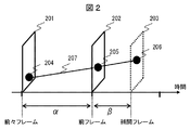
- FIG. 2 is a diagram for explaining an extrapolated frame interpolation technique used in this embodiment among the frame interpolation techniques.
- the video frame 201 is stored in the temporary storage unit 113
- the video frame 202 is stored in the temporary storage unit 112.
- the frame interpolation unit 114 calculates a motion vector from the motion of the subject in the video frames 201 and 202. For example, when it is determined that the subject 205 on the video frame 202 is the same as the subject 204 on the video frame 201, the motion vector is 207.
- the calculation of the motion vector of the subject may be performed for each pixel or for each block.
- the subject 205 is moved to a position where the motion vector 207 is ⁇ / ⁇ to create the interpolation frame 203 as the subject 206. .
- the technique for creating an interpolation frame in this way is called an extrapolation type frame interpolation technique, and a video frame created by the extrapolation type frame interpolation technique is called an extrapolation type frame interpolation picture.
- this extrapolated frame interpolated video is used as an interpolated frame, thereby realizing video display with little delay with respect to the input of the video display device while maintaining smoothness of the motion of the displayed video.
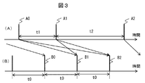
- FIG. 3 is a diagram for explaining video input to the video display device and display timing in this embodiment.
- FIG. 3A shows video frames (A0, A1, A2) transmitted from the video output device and input to the video display device
- FIG. 3B shows a video frame ( B0, B1, B2). That is, while the frame interval of the video output device fluctuates and is t1 or t2, the frame rate on the video display device side is fixed to t0.
- the frame interpolation unit 114 uses the input images A1 and A0 received at a timing before B1 to perform extrapolation as described in FIG.
- the frame is interpolated to create the B1 frame and then displayed.
- the A1 image is stored in the temporary storage unit 112 and the A0 image is stored in the temporary storage unit 113 in FIG.
- the video display device when the video display device tries to output a video frame at the timing of B2, an extrapolated frame as shown in FIG. 2 using the input images A1 and A0 received at a timing before B1. Display is performed after interpolation is performed to create a frame of B2.
- the control unit 116 controls which input video is used to create the interpolation frame.
- the values of ⁇ and ⁇ as shown in FIG. 2 are calculated for each output frame in accordance with the temporal positional relationship between the interpolation frame and the reception frame. Note that the number of frames used for the frame interpolation is not limited to two, and interpolation may be performed with a plurality of frames.
- the configuration block diagram of the video display apparatus in the present embodiment is the same as that of FIG. In FIG. 1, since the operation of the frame interpolation unit 114 is different from that of the first embodiment, the operation of the frame interpolation unit 114 will be described. That is, in the first embodiment, the frame interpolation unit 114 uses an extrapolation type frame interpolation technique as shown in FIG. 2, whereas in this embodiment, an interpolation type frame interpolation technique as shown in FIG. Is used.
- FIG. 4 is a diagram for explaining an interpolated frame interpolation technique used in the present embodiment among the frame interpolation techniques.
- the video frame 401 is stored in the temporary storage unit 113
- the video frame 403 is stored in the temporary storage unit 112.
- the frame interpolation unit 114 calculates a motion vector from the motion of the subject of the video frames 401 and 403. For example, when it is determined that the subject 406 on the video frame 403 is the same as the subject 404 on the video frame 401, the motion vector is 407.
- the position of the subject 404 is moved to a position where the motion vector 407 is ⁇ / ( ⁇ + ⁇ ) as a subject 405.
- An interpolation frame 402 is created. This makes it possible to predict and create an interpolation frame 402 between the video frame 401 and the video frame 403.
- interpolation type frame interpolation technique The technique for creating an interpolation frame in this way is called an interpolation type frame interpolation technique, and a video frame created by the interpolation type frame interpolation technique is called an interpolation type frame interpolation picture.
- this interpolated frame interpolated video as an interpolated frame, a delay of the displayed video with respect to the input video signal occurs, but a higher quality video while maintaining the smoothness of the motion of the displayed video. Display can be realized.
- FIG. 5 is a diagram for explaining video input to the video display device and display timing in this embodiment.
- FIG. 5A shows video frames (A0, A1, A2) transmitted from the video output device and input to the video display device
- FIG. 5B shows a video frame displayed by the video display device. (B0, B1, B2) are shown.
- the frame interpolation unit 114 uses the input images A0 and A1 received at timings before and after B0 to interpolate as shown in FIG.
- the frame is interpolated to create a B0 frame for display.
- the A1 image is stored in the temporary storage unit 112 and the A0 image is stored in the temporary storage unit 113 in FIG.
- the control unit 116 controls which input video is used to create the interpolation frame.
- an interpolation type frame as shown in FIG. 4 is used by using the input images A1 and A2 received at timings before and after B1. Interpolate to create a frame B1 and display it. Further, the values of ⁇ and ⁇ as shown in FIG. 4 are calculated for each output frame in accordance with the temporal positional relationship between the interpolation frame and the reception frame. Note that the number of frames used for the frame interpolation is not limited to two, and interpolation may be performed with a plurality of frames.
- the display since the display is performed at a timing later than the video that has already been transmitted, there is a demerit that the time difference between the display time of the displayed video and the input video becomes large. If the video frame created by the interpolated frame interpolation technique has higher image quality than the interpolated frame interpolation technique, and if the video delay is acceptable, use the interpolated frame interpolation technique. Thus, it is possible to display with high image quality while maintaining smoothness of movement.
- frame interpolation may be performed by combining the extrapolation type frame interpolation and the interpolation type frame interpolation of the first embodiment.
- the video display apparatus can switch between using a video frame by frame interpolation or using a transmitted video frame, and can reduce image quality degradation caused by using a frame-interpolated image.
- FIG. 6 is a block diagram showing the configuration of the video display system in the present embodiment.
- the video output device 10 and the video display device 11 are connected by HDMI (abbreviation of High-Definition-Multimedia Interface; HDMI, registered trademark of LLC) and the video signal output from the video output device 10 is displayed as a video display device.
- 11 is assumed to be a system for transmitting images to 11 and displaying images.
- the internal configuration of the video output apparatus 10 includes a drawing unit 101, a transmission unit 102, a control unit 103, and a drawing time prediction unit 104.
- the same functional configuration as in FIG. 1 is that a video switching unit 117 is provided.
- the video output device 10 outputs the frame drawn by the drawing unit 101 from the transmission unit 102 to the video display device 11 as a video signal under the control of the control unit 103.
- the drawing time prediction unit 104 predicts the drawing time required for drawing the next frame based on the drawing contents, calculates the frame interval from the prediction result until the next frame is output as a video signal, and the transmission unit 102. Is output to the video display device 11 as information about the frame interval together with the video signal drawn by the drawing unit 101.
- the control unit 116 and the video output device 10 of the video display device 11 exchange control information through, for example, an HDMI video transmission line connecting the transmission unit 102 and the reception unit 111, and the video signal is within a range that the video display device 11 can handle. Format, and send / receive video signal metadata. Information about the frame interval received by the receiving unit 111 is transmitted to the control unit 116, and the control unit 116 controls the temporary storage units 112 and 113, the frame interpolation unit 114, and the display element 115 based on the information about the frame interval.
- the operation after confirming that the transmission frame interval is a combination of a video output device capable of transmitting a video format having different transmission frame intervals and metadata of the transmission frame interval and a video display device capable of receiving the metadata.
- the video switching unit 117 switches between using a frame-interpolated video or using a transmitted video frame as it is. This switching is performed when the timing at which the video signal that is the predicted video frame interval calculated using the information about the frame interval transmitted from the video output device is close to the timing at which the video display device tries to display Then, the video frame is switched to the transmitted video frame, and when it is not close to the timing at which the video display device tries to display, the video frame is interpolated. By this switching, it is possible to reduce the frequency of using the frame-interpolated video, and it is possible to suppress image quality deterioration due to frame interpolation.
- Whether the video display device 11 is close to the timing to display is determined by the absolute value of the difference between the time to display and the timing at which the video signal calculated from the information about the transmitted frame interval is input. The determination may be made based on whether or not the value is within the preset threshold value TH.
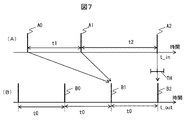
- FIG. 7 is a diagram for explaining video input to the video display device and display timing in the present embodiment.
- FIG. 7A shows video frames (A0, A1, A2) transmitted from the video output device and input to the video display device
- FIG. 7B shows a video frame displayed by the video display device. (B0, B1, B2) are shown.
- the video switching unit 117 compares the timing at which the video display device outputs video with the timing at which the video signal is input to the video display device. It is compared whether or not the difference between the video display time t_out and the video reception time t_in is within the threshold value TH. When
- a frame is output.
- the received video frame is output.
- the A1 image is stored in the temporary storage unit 112 and the A0 image is stored in the temporary storage unit 113 in FIG.
- the video display device tries to output a video frame at the timing B2
- the difference between the timing (A2) at which the video signal is input and the display time (B2) of the video to be output is based on the threshold value TH. Since it is small, the received video frame A2 is displayed on the display element.
- This switching operation can also be used when the video does not reach the information output by the video output device. In other words, if for some reason the video does not reach the display interval output by the video output device, instead of switching to the transmission frame side, switch to the frame-interpolated video and output for the convenience of the video output device. Even if the video is delayed, high-quality display is possible while maintaining smooth movement.
- Video output device 11: Video display device, 101: Drawing unit, 102: Transmission unit, 103: Control unit, 104: Drawing time prediction unit, 110: Video signal, 111: Reception unit, 112, 113: Temporary storage , 114: Frame interpolation unit, 115: Display element, 201, 202: Video frame, 203: Interpolation frame, 204, 205, 206: Subject, 207: Motion vector indicating the motion of the subject, 401, 403: Video frame, 402: Interpolated frame, 404, 405, 406: Subject, 407: Motion vector
Landscapes
- Engineering & Computer Science (AREA)
- Multimedia (AREA)
- Signal Processing (AREA)
- Television Systems (AREA)
Abstract
表示フレームレートが不規則に可変するフレームレートの映像を受信し、映像フレームを等間隔の固定フレームレートで表示する表示部に表示する際に、表示される映像の動きの滑らかさを考慮した高画質な表示を実現することを目的とする。 そのために、映像フレームレートが変動する映像信号を受信して、映像フレームを等間隔の固定フレームレートで表示する映像表示装置であって、映像受信部で受信した映像を表示部で表示する映像に変換する映像変換部を備え、映像変換部は、受信する映像フレームのうち、表示部が表示で用いる等間隔のタイミングと合わないタイミングで受信した第1のフレームについては、第1のフレームと第1のフレームよりも前に受信部で受信した第2のフレームを用いた時間方向補間処理により表示部が表示で用いる等間隔のタイミングのフレームである第3のフレームを生成し、表示部へ出力するように構成する。
Description
本発明は、映像信号を入力して表示する映像表示装置、それを用いた映像表示システム、及び映像表示方法に関する。
従来、映像出力装置からの映像信号を入力して表示する映像表示装置において、映像出力装置の出力するフレームレートに合わせて映像表示装置のフレームレートを変換するフレームレート変換技術が知られている。例えば、映像表示装置において、画像の描画処理時間とフレームレートから算出した1画面の出力時間とに基づいて表示のタイミングであるフレームレートを修正したり、映像表示装置のフレームレートのタイミングで映像出力装置から映像信号が得られない場合は前フレームを繰り返し表示するなどのフレームレート変換技術が知られている。
しかし、上記のようなフレームレート変換技術では、映像出力装置のフレームレート変動に合わせて映像表示装置のフレームレートを変更しているため、特に映像表示装置のフレームレートが固定である場合の映像表示の滑らかさに関して考慮していない。すなわち、固定フレームレートで表示を行う映像表示装置に対して、映像出力装置からフレームレートが変動する映像を入力すると、映像信号出力装置と映像表示装置のタイミングが合わないため、映像自体が表示されなかったり、時間的にずれた映像を表示することになるため、動きのある映像に対しては、本来動き続けて表示されるべき映像が動いたり止まったりして見える、いわゆるモーションジャダーと呼ばれる画質劣化が生じる場合がある。
これらの技術に関する背景技術として、特許文献1がある。特許文献1では、映像表示装置が受信した複数の映像フレームから被写体の動きを追跡することで、動きベクトルを探索し、その動きベクトルに応じて、映像フレームに含まれる被写体の位置を移動させた新たな映像フレームを生成する動き補正型のフレーム補間技術が開示されている。この動き補正型フレーム補間技術は、上記モーションジャダーによる画質劣化の抑圧に有効であり、画質劣化の少ない高画質な表示が可能である。
しかし、特許文献1に記載されているフレームレート変換技術は、一般的に、固定フレームレートから固定フレームレートへの変換を想定している。例えばフレームレート24Hzの映像入力を60Hzのフレームレートで表示したり、フレームレート50Hzの映像入力を60Hzに変換して出力したりするときに用いられる。また、フレームレート変換に伴う遅延を許容しており、基本的に可変フレームレートの映像が入力されることを想定していない。
本発明の目的は、フレームレートが変動する映像出力装置の映像を、固定フレームレートの映像表示装置に、動きの滑らかさを損なわずに表示することが可能な映像表示装置、映像表示システム、及び映像表示方法を提供することにある。
本発明は、上記背景技術及び課題に鑑み、その一例を挙げるならば、映像フレームレートが変動する映像信号を受信して、映像フレームを等間隔の固定フレームレートで表示する映像表示装置であって、映像受信部と、表示部と、映像受信部で受信した映像を表示部で表示する映像に変換する映像変換部とを備え、映像変換部は、映像受信部で受信する映像フレームのうち、表示部が表示で用いる等間隔のタイミングと合わないタイミングで受信した第1のフレームについては、第1のフレームと前記第1のフレームよりも前に映像受信部で受信した第2のフレームを用いた時間方向補間処理により表示部が表示で用いる等間隔のタイミングのフレームである第3のフレームを生成し、第3のフレームを表示部へ出力するように構成する。
本発明によれば、フレーム周期が変動する映像出力装置の映像を固定フレームレートの映像表示装置に入力しても、動きの滑らかさを保ちつつ高画質に表示することが可能となる映像表示装置、映像表示システム、及び映像表示方法を提供することができる。
以下、本発明の実施例を、図面を用いて説明する。
本実施例では、フレーム毎にフレーム周期が変動する映像信号を固定フレームレートの映像表示装置に表示する際に、入力映像信号に対して可能な限り遅延を少なくして表示する方法に関して説明する。
図1は、本実施例における映像表示装置の構成を示すブロック図である。図1において、映像表示装置11は、制御部116の制御下において、映像出力装置より出力され伝送されてきた映像信号110を受信部111が受信し、映像信号が一時記憶部(フレームメモリ:FM)112および113、フレーム補間部114、表示素子115を介して表示される。
一方、受信部111が受信した映像信号110のフレーム間隔情報は制御部116へ送信され、制御部116がフレーム間隔情報に基づいて一時記憶部112および113、フレーム補間部114、表示素子115を制御して、表示素子のフレームレートに合わせた映像フレームを作成し表示する。これにより、動きの滑らかさを保ちつつ高画質表示を実現できる。
なお、本実施例においては、受信された2つのフレームから補間フレームを作る例を示しているが、より多くのフレームを用いて補間フレームを作成することも可能である。フレーム補間技術に関しては、特許文献1などに記載の技術を用いればよい。
また、本実施例は、固定フレームレートの映像表示装置であることを想定しており、表示素子の種類は問わない。現在一般的に用いられているLCD,OLED,CRTのどれであっても構わないし、あるいは、表示素子との間に、何らかの信号処理装置があっても構わない。
図2は、フレーム補間技術のうち、本実施例で用いる外挿形のフレーム補間技術を説明する図である。図2において、映像フレーム201は、一時記憶部113に記憶され、映像フレーム202は、一時記憶部112に記憶されている。フレーム補間部114は、映像フレーム201と202の映像の被写体の動きから動きベクトルを算出する。例えば、映像フレーム202上の被写体205が、映像フレーム201上の被写体204と同一であると判断された場合は、動きベクトルは207のようになる。この被写体の動きベクトルの算出は、画素毎に行ってもいいし、ブロック単位で行ってもよい。
映像フレーム201と202の時間間隔をα、映像フレーム202と補間フレーム203の時間間隔をβとすると、動きベクトル207をβ/αした位置に被写体205を動かして被写体206として補間フレーム203を作成する。これにより、映像フレーム202よりも時間的に後の補間フレーム203を予測して作ることが可能となる。
このようにして補間フレームを作成する技術を外挿型フレーム補間技術と呼び、外挿型フレーム補間技術により作成された映像フレームを外挿型フレーム補間映像と呼ぶ。本実施例は、補間フレームとして、この外挿型フレーム補間映像を用いることで、表示映像の動きの滑らかさを保ちつつ、映像表示装置の入力に対する遅延の少ない映像表示を実現する。
図3は、本実施例における、映像表示装置への映像入力と表示タイミングを説明する図である。図3(A)は、映像出力装置より伝送され映像表示装置への入力となる映像フレーム(A0,A1,A2)を示し、図3(B)は、映像表示装置により表示される映像フレーム(B0,B1,B2)を示している。すなわち、映像出力装置のフレーム間隔が変動しt1であったりt2であったりするのに対し、映像表示装置側のフレームレートは固定でt0であることを示している。
フレーム補間部114は、映像表示装置がB1のタイミングの映像フレームを出力しようとする際には、B1より前のタイミングで受信した入力画像A1,A0を用いて図2で説明したような外挿型のフレーム補間を行いB1のフレームを作り出してから表示を行う。この例の場合、図1における一時記憶部112にA1の画像、一時記憶部113にA0の画像が記憶されていることになる。
同様に、映像表示装置がB2のタイミングの映像フレームを出力しようとする際には、B1より前のタイミングで受信した入力画像A1,A0を用いて図2に示されるような外挿型のフレーム補間を行いB2のフレームを作り出してから表示を行う。どの入力映像を用いて補間フレームを作成するかは制御部116により制御される。また、補間フレームと受信フレームの時間的位置関係に応じて図2に記載されているようなα、βの値が出力フレーム毎に計算される。なお、上記フレーム補間に用いるフレームは2つに限定されず、複数のフレームで補間してもよい。
以上のように外挿型のフレーム補間技術を用いることで、描画時間に依存してフレーム毎にフレーム周期が変動する映像信号を、固定フレームレートの映像表示装置に入力しても、動きの滑らかさを保ちつつ高画質に表示することが可能となる。
言い換えれば、フレーム周期が変動する映像信号が、映像表示装置側で想定した時間に届かなかった場合は、過去に受信した複数の映像フレームから、映像表示装置が表示する時間タイミングの映像を動き補正型のフレーム補間技術により予測して作りだし、表示時間タイミングにおいて、この予測して作り出した映像フレームを表示することで、動きの滑らかさを保ちつつ高画質に表示することが可能となる。
本実施例では、フレーム毎にフレーム周期が変動する映像信号を固定フレームレートの映像表示装置に表示する際に、入力映像信号に対する表示映像の遅延を許容することで、動きの滑らかを保ちつつ、実施例1の場合よりも高画質で表示を行う表示方法に関して説明する。
本実施例における映像表示装置の構成ブロック図は実施例1の図1と同様である。図1において、フレーム補間部114の動作が実施例1とは異なるため、フレーム補間部114の動作に関して説明する。すなわち、実施例1では、フレーム補間部114が図2に示すような外挿型のフレーム補間技術を用いていたのに対し、本実施例では図4に示すような内挿型のフレーム補間技術を用いる。
図4は、フレーム補間技術のうち、本実施例で用いる内挿形のフレーム補間技術を説明する図である。図4において、映像フレーム401は、一時記憶部113に記憶され、映像フレーム403は、一時記憶部112に記憶されている。フレーム補間部114は、映像フレーム401と403の映像の被写体の動きから動きベクトルを算出する。例えば、映像フレーム403上の被写体406が、映像フレーム401上の被写体404と同一であると判断された場合は、動きベクトルは407のようになる。
映像フレーム401と補間フレーム402の時間間隔をα、映像フレーム403と補間フレーム402の時間間隔をβとすると、動きベクトル407をα/(α+β)した位置に被写体404の位置を動かして被写体405として補間フレーム402を作成する。これにより、映像フレーム401と映像フレーム403の間にある補間フレーム402を予測して作ることが可能となる。
このようにして補間フレームを作成する技術を内挿型のフレーム補間技術と呼び、内挿型のフレーム補間技術により作成された映像フレームを内挿型フレーム補間映像と呼ぶ。本実施例は、補間フレームとして、この内挿型フレーム補間映像を用いることで、入力映像信号に対する表示映像の遅延が発生するが、表示映像の動きの滑らかさを保ちつつ、より高画質な映像表示を実現できる。
図5は、本実施例における、映像表示装置への映像入力と表示タイミングを説明する図である。図5(A)は、映像出力装置より伝送され、映像表示装置への入力となる映像フレーム(A0,A1,A2)を示し、図5(B)は、映像表示装置により表示される映像フレーム(B0,B1,B2)を示している。
フレーム補間部114は、映像表示装置がB0のタイミングの映像フレームを出力しようとする際には、B0と前後するタイミングで受信した入力画像A0,A1を用いて図4に示されるような内挿型のフレーム補間を行いB0のフレームを作り出して表示を行う。この例の場合、図1における一時記憶部112にA1の画像、一時記憶部113にA0の画像が記憶されていることになる。どの入力映像を用いて補間フレームを作成するかは制御部116により制御される。
同様に、映像表示装置がB1のタイミングの映像フレームを出力しようとする際には、B1と前後するタイミングで受信した入力画像A1,A2を用いて図4に示されるような内挿型のフレーム補間を行いB1のフレームを作り出して表示を行う。また、補間フレームと受信フレームの時間的位置関係に応じて図4に記載されているようなα、βの値が出力フレーム毎に計算される。なお、上記フレーム補間に用いるフレームは2つに限定されず、複数のフレームで補間してもよい。
本実施例の場合、既に伝送されてきた映像より遅いタイミングで表示することになるため、表示される映像の表示時間と、入力映像の時間差が大きくなるというデメリットがあるが、一般的に外挿型フレーム補間技術よりも内挿型フレーム補間技術により作成した映像フレームの方が、画像の品質が高いため、映像の遅延が許容できる場合であれば、内挿型のフレーム補間技術を使うことで、動きの滑らかさを保ちつつ高画質に表示することが可能となる。
なお、実施例1の外挿型フレーム補間と内挿型フレーム補間を組み合わせてフレーム補間を行ってもよい。
本実施例では、映像出力装置から映像表示装置に表示タイミングであるフレーム間隔に関する情報を伝送する場合について説明する。この場合、映像表示装置は、フレーム補間による映像フレームを使うか、伝送されてきた映像フレームを使うかの切り替えが可能となり、フレーム補間画像を使うことによる画質劣化を低減することが可能となる。
図6は、本実施例における映像表示システムの構成を示すブロック図である。本実施例では、例えば映像出力装置10と映像表示装置11をHDMI(High Definition Multimedia Interfaceの略称。HDMI, LLCの登録商標)などで接続し、映像出力装置10が出力した映像信号を映像表示装置11へ伝送して映像を表示するシステムを想定する。
図6において、映像出力装置10の内部構成は、描画部101と送信部102、制御部103、描画時間予測部104を有する。一方、映像表示装置11の内部構成において、図1と同じ機能の構成は同じ符号を付しており、その説明は省略する。図1と異なる点は、映像切り替え部117を有する点である。
この映像表示システムでは、映像出力装置10は制御部103の制御下において、描画部101が描画したフレームを送信部102から映像表示装置11へ映像信号として出力する。同時に描画時間予測部104が次のフレームの描画にかかる描画時間を描画内容に基づいて予測し、その予測結果から次のフレームを映像信号として出力するまでのフレーム間隔を算出して、送信部102が描画部101の描画した映像信号と共に、フレーム間隔に関する情報として映像表示装置11へ出力する。
映像表示装置11の制御部116と映像出力装置10は、送信部102と受信部111を結ぶ例えばHDMIの映像伝送線を通じて、制御情報を交換し、映像表示装置11が対応可能な範囲で映像信号のフォーマットを決め、映像信号のメタデータを送受信する。受信部111が受信したフレーム間隔に関する情報は制御部116へ伝えられ、制御部116がフレーム間隔に関する情報に基づいて一時記憶部112および113、フレーム補間部114、表示素子115を制御する。
以下の説明では、伝送フレーム間隔がフレーム毎に異なる映像フォーマットとその伝送フレーム間隔のメタデータを送信できる映像出力装置と、受信できる映像表示装置の組合せであることを確認後の動作としている。
映像切り替え部117は、フレーム補間された映像を用いるのか、伝送されてきた映像フレームをそのまま使うかを切り替える。この切り替えは、映像出力装置より伝送されてきたフレーム間隔に関する情報を利用して算出した映像フレーム間隔予測値である映像信号が入力されるタイミングと、映像表示装置が表示しようとするタイミングが近い場合、伝送されてきた映像フレームに切り替え、映像表示装置が表示しようとするタイミングに近くない場合、フレーム補間された映像に切り替える。この切り替えにより、フレーム補間映像を使う頻度を減らすことが可能となり、フレーム補間による画質劣化を抑えることが可能となる。映像表示装置11が表示しようとするタイミングに近いかどうかは、表示しようとする時間に対して、伝送されてくるフレーム間隔に関する情報から算出した映像信号が入力されるタイミングとの差の絶対値が、あらかじめ設定したしきい値TH以内に入っているかどうかにより判定すればよい。
この切り替え動作を、図7を用いて説明する。図7は、本実施例における、映像表示装置への映像入力と表示タイミングを説明する図である。図7(A)は、映像出力装置より伝送され、映像表示装置への入力となる映像フレーム(A0,A1,A2)を示し、図7(B)は、映像表示装置により表示される映像フレーム(B0,B1,B2)を示している。映像切り替え部117は、映像表示装置が映像を出力するタイミングと、映像表示装置に映像信号が入力されるタイミングとを比較する。映像表示時間t_outに対して、映像受信時間t_inの差が、スレッショルド値TH以内にあるかどうかを比較し、|t_out-t_in|>=THの場合には、フレーム補間部114に作成された補間フレームを出力し、|t_out-t_in|<THの場合には、受信した映像フレームの方を出力する。例えば、図7に示すB1のタイミングの映像フレームを出力しようとする際には、B1より前のタイミングで受信した入力画像A1,A0を用いて図2で説明したような外挿型のフレーム補間を行い、B1のフレームを作り出してから表示を行う。この例の場合、図6における一時記憶部112にA1の画像、一時記憶部113にA0の画像が記憶されていることになる。同様に、映像表示装置がB2のタイミングの映像フレームを出力しようとする際には、映像信号が入力されるタイミング(A2)と出力する映像の表示時間(B2)との差がスレッショルド値THより小さいため、受信した映像フレームA2の方を表示素子に表示する。
なお、上記では、フレーム補間の例として、外挿型のフレーム補間を用いて説明したが、内挿型のフレーム補間を用いて、受信した映像フレームとを切り替えるようにしてもよい。
また、この切り替え動作は、映像出力装置の出力する情報どおりに映像が届かなかった場合にも活用可能である。すなわち、何らかの理由で映像出力装置の出力する表示間隔どおりに映像が届かなかった場合には、伝送フレーム側に切り替えるのではなく、フレーム補間された映像に切り替えることで、映像出力装置の都合で出力が遅れてしまった映像であっても、動きの滑らかさを保ちつつ高画質な表示が可能となる。
10:映像出力装置、11:映像表示装置、101:描画部、102:送信部、103:制御部、104:描画時間予測部、110:映像信号、111:受信部、112、113:一時記憶部、114:フレーム補間部、115:表示素子、201、202:映像フレーム、203:補間フレーム、204、205、206:被写体、207:被写体の動きを示す動きベクトル、401、403:映像フレーム、402:補間フレーム、404、405、406:被写体、407:動きベクトル
Claims (10)
- 映像フレームレートが変動する映像信号を受信して、映像フレームを等間隔の固定フレームレートで表示する映像表示装置であって、
映像受信部と、表示部と、前記映像受信部で受信した映像を前記表示部で表示する映像に変換する映像変換部とを備え、
前記映像変換部は、前記映像受信部で受信する映像フレームのうち、前記表示部が表示で用いる等間隔のタイミングと合わないタイミングで受信した第1のフレームについては、前記第1のフレームと前記第1のフレームよりも前に前記映像受信部で受信した第2のフレームを用いた時間方向補間処理により前記表示部が表示で用いる等間隔のタイミングのフレームである第3のフレームを生成し、前記第3のフレームを前記表示部へ出力することを特徴とする映像表示装置。 - 請求項1に記載の映像表示装置であって、
前記第3のフレームは、前記表示部が表示で用いる等間隔のタイミングであって前記第1のフレームの受信タイミングよりも後のタイミングのフレームであり、
前記時間方向補間処理は、外挿型フレーム補間であることを特徴とする映像表示装置。 - 請求項1に記載の映像表示装置であって、
前記第3のフレームは、前記表示部が表示で用いる等間隔のタイミングであって前記第1のフレームの受信タイミングよりも前のタイミングであり、かつ、前記第2のフレームの受信タイミングよりも後のフレームであり、
前記時間方向補間処理は、内挿型フレーム補間であることを特徴とする映像表示装置。 - 請求項1に記載の映像表示装置であって、
前記映像信号に付与されたフレーム間隔に関する情報を受信し、受信した映像フレームを表示するか、前記時間方向補間処理により補間したフレームを表示するかを選択する映像切り替え部を有することを特徴とする映像表示装置。 - 映像フレーム単位で映像信号を出力する映像出力装置と該映像出力装置から受信した映像フレームを表示する映像表示装置から構成される映像表示システムであって、
前記映像出力装置は、第1フレームと第2フレーム間のフレーム間隔に関する情報を前記映像信号に付与して出力し、
前記映像表示装置は、前記フレーム間隔に関する情報を受信して、前記映像信号が入力されるタイミングを取得するとともに、該映像信号が入力されるタイミングに応じて、受信した前記映像信号の映像フレームを表示するか、時間方向補間処理により補間したフレームを出力するかを選択する映像切り替え部を有することを特徴とする映像表示システム。 - 請求項5に記載の映像表示システムであって、
前記時間方向補間処理は、外挿型フレーム補間であることを特徴とする映像表示システム。 - 映像フレームレートが変動する映像信号を受信して、映像フレームを等間隔の固定フレームレートで表示する映像表示方法であって、
前記等間隔の固定フレームレートのタイミングと合わないタイミングで受信した第1のフレームについては、該第1のフレームと該第1のフレームよりも前に受信した第2のフレームを用いた時間方向補間処理により前記等間隔のタイミングのフレームである第3のフレームを生成し、該第3のフレームを表示することを特徴とする映像表示方法。 - 請求項7に記載の映像表示方法であって、
前記第3のフレームは、前記等間隔のタイミングであって前記第1のフレームの受信タイミングよりも後のタイミングのフレームであり、
前記時間方向補間処理は、外挿型フレーム補間であることを特徴とする映像表示方法。 - 請求項7に記載の映像表示方法であって、
前記第3のフレームは、前記等間隔のタイミングであって前記第1のフレームの受信タイミングよりも前のタイミングであり、かつ、前記第2のフレームの受信タイミングよりも後のフレームであり、
前記時間方向補間処理は、内挿型フレーム補間であることを特徴とする映像表示方法。 - 請求項7に記載の映像表示方法であって、
前記映像信号に付与されたフレーム間隔に関する情報を受信し、受信した映像フレームを表示するか、前記時間方向補間処理により補間したフレームを表示するかを選択することを特徴とする映像表示方法。
Priority Applications (1)
| Application Number | Priority Date | Filing Date | Title |
|---|---|---|---|
| PCT/JP2017/017786 WO2018207298A1 (ja) | 2017-05-11 | 2017-05-11 | 映像表示装置、映像表示システム、及び映像表示方法 |
Applications Claiming Priority (1)
| Application Number | Priority Date | Filing Date | Title |
|---|---|---|---|
| PCT/JP2017/017786 WO2018207298A1 (ja) | 2017-05-11 | 2017-05-11 | 映像表示装置、映像表示システム、及び映像表示方法 |
Publications (1)
| Publication Number | Publication Date |
|---|---|
| WO2018207298A1 true WO2018207298A1 (ja) | 2018-11-15 |
Family
ID=64104693
Family Applications (1)
| Application Number | Title | Priority Date | Filing Date |
|---|---|---|---|
| PCT/JP2017/017786 Ceased WO2018207298A1 (ja) | 2017-05-11 | 2017-05-11 | 映像表示装置、映像表示システム、及び映像表示方法 |
Country Status (1)
| Country | Link |
|---|---|
| WO (1) | WO2018207298A1 (ja) |
Cited By (2)
| Publication number | Priority date | Publication date | Assignee | Title |
|---|---|---|---|---|
| US20230123776A1 (en) * | 2020-06-23 | 2023-04-20 | Samsung Electronics Co., Ltd. | Electronic device for dynamically adjusting refresh rate of display |
| EP4304167A4 (en) * | 2021-06-14 | 2024-11-20 | Samsung Electronics Co., Ltd. | Electronic device carrying out video call by using frc, and operation method for electronic device |
Citations (3)
| Publication number | Priority date | Publication date | Assignee | Title |
|---|---|---|---|---|
| JPH11297260A (ja) * | 1998-04-13 | 1999-10-29 | Hitachi Ltd | 画像表示装置 |
| JP2000358221A (ja) * | 1999-06-14 | 2000-12-26 | Olympus Optical Co Ltd | 画像表示装置 |
| US20130022130A1 (en) * | 2006-04-05 | 2013-01-24 | Stmicroelectronics S.R.L. | Method for the frame-rate conversion of a video sequence of digital images, related apparatus and computer program product |
-
2017
- 2017-05-11 WO PCT/JP2017/017786 patent/WO2018207298A1/ja not_active Ceased
Patent Citations (3)
| Publication number | Priority date | Publication date | Assignee | Title |
|---|---|---|---|---|
| JPH11297260A (ja) * | 1998-04-13 | 1999-10-29 | Hitachi Ltd | 画像表示装置 |
| JP2000358221A (ja) * | 1999-06-14 | 2000-12-26 | Olympus Optical Co Ltd | 画像表示装置 |
| US20130022130A1 (en) * | 2006-04-05 | 2013-01-24 | Stmicroelectronics S.R.L. | Method for the frame-rate conversion of a video sequence of digital images, related apparatus and computer program product |
Cited By (3)
| Publication number | Priority date | Publication date | Assignee | Title |
|---|---|---|---|---|
| US20230123776A1 (en) * | 2020-06-23 | 2023-04-20 | Samsung Electronics Co., Ltd. | Electronic device for dynamically adjusting refresh rate of display |
| US11842670B2 (en) * | 2020-06-23 | 2023-12-12 | Samsung Electronics Co., Ltd. | Electronic device for dynamically adjusting refresh rate of display |
| EP4304167A4 (en) * | 2021-06-14 | 2024-11-20 | Samsung Electronics Co., Ltd. | Electronic device carrying out video call by using frc, and operation method for electronic device |
Similar Documents
| Publication | Publication Date | Title |
|---|---|---|
| EP0918436B1 (en) | Conversion of decoded interlaced video into progressive scanning system taking account of scanning system before coding | |
| JP2009532984A (ja) | 補償アーチファクトに対する保護を有する動き補償フレームレート変換 | |
| JP2003174628A (ja) | 動き補償補間のための画素値選択装置及び方法 | |
| US7295245B2 (en) | Method and apparatus for converting frame rate using time shifting and motion compensation | |
| EP1592246A1 (en) | Film mode determination in video image still areas | |
| JP2000050212A (ja) | 画像表示装置及び画像表示方法 | |
| JP5177828B2 (ja) | 画像レート変換方法及び画像レート変換装置 | |
| WO2018207298A1 (ja) | 映像表示装置、映像表示システム、及び映像表示方法 | |
| JP2003189259A (ja) | 画像信号処理装置及び方法 | |
| EP1592249B1 (en) | Reverse film mode extrapolation | |
| JP2000259146A (ja) | 画像表示装置 | |
| JP3898546B2 (ja) | 画像走査変換方法及び装置 | |
| US8279931B2 (en) | Motion vector estimator for reducing film judder | |
| JP2010011108A (ja) | 画像処理装置および方法、並びにプログラム | |
| CN108282653B (zh) | 基于双极性场的运动估计的运动补偿去隔行方法及系统 | |
| GB2476298A (en) | Changing the temporal sample rate of a motion image sequence | |
| JP4956239B2 (ja) | フレームレート変換装置および映像表示装置 | |
| EP1592254A1 (en) | Film mode extrapolation | |
| KR102121395B1 (ko) | 영상 프레임 보간 장치, 디스플레이 장치 및 그 제어 방법 | |
| KR100850710B1 (ko) | 위상 정정 필드를 이용한 적응적 디-인터레이싱 방법 및그 장치와, 이를 구현하기 위한 프로그램이 기록된 기록매체 | |
| JP2019083433A (ja) | 映像送信装置、映像受信装置及びプログラム | |
| KR100587263B1 (ko) | 비디오 신호의 프레임 율 변환 방법 | |
| JP2009147767A (ja) | 画像変換装置、画像表示装置 | |
| JP4354799B2 (ja) | 補間画像生成方法および装置 | |
| JP4910579B2 (ja) | 画像信号処理装置、画像信号処理方法、およびプログラム |
Legal Events
| Date | Code | Title | Description |
|---|---|---|---|
| 121 | Ep: the epo has been informed by wipo that ep was designated in this application |
Ref document number: 17909086 Country of ref document: EP Kind code of ref document: A1 |
|
| NENP | Non-entry into the national phase |
Ref country code: DE |
|
| 122 | Ep: pct application non-entry in european phase |
Ref document number: 17909086 Country of ref document: EP Kind code of ref document: A1 |
|
| NENP | Non-entry into the national phase |
Ref country code: JP |