WO2018203395A1 - User terminal, wireless base station, and wireless communication method - Google Patents
User terminal, wireless base station, and wireless communication method Download PDFInfo
- Publication number
- WO2018203395A1 WO2018203395A1 PCT/JP2017/017292 JP2017017292W WO2018203395A1 WO 2018203395 A1 WO2018203395 A1 WO 2018203395A1 JP 2017017292 W JP2017017292 W JP 2017017292W WO 2018203395 A1 WO2018203395 A1 WO 2018203395A1
- Authority
- WO
- WIPO (PCT)
- Prior art keywords
- pattern
- user
- user terminal
- dmrs
- mapping
- Prior art date
Links
Images


Classifications
-
- H—ELECTRICITY
- H04—ELECTRIC COMMUNICATION TECHNIQUE
- H04L—TRANSMISSION OF DIGITAL INFORMATION, e.g. TELEGRAPHIC COMMUNICATION
- H04L5/00—Arrangements affording multiple use of the transmission path
- H04L5/003—Arrangements for allocating sub-channels of the transmission path
- H04L5/0048—Allocation of pilot signals, i.e. of signals known to the receiver
- H04L5/0051—Allocation of pilot signals, i.e. of signals known to the receiver of dedicated pilots, i.e. pilots destined for a single user or terminal
-
- H—ELECTRICITY
- H04—ELECTRIC COMMUNICATION TECHNIQUE
- H04L—TRANSMISSION OF DIGITAL INFORMATION, e.g. TELEGRAPHIC COMMUNICATION
- H04L25/00—Baseband systems
- H04L25/02—Details ; arrangements for supplying electrical power along data transmission lines
- H04L25/0202—Channel estimation
- H04L25/0224—Channel estimation using sounding signals
- H04L25/0226—Channel estimation using sounding signals sounding signals per se
-
- H—ELECTRICITY
- H04—ELECTRIC COMMUNICATION TECHNIQUE
- H04W—WIRELESS COMMUNICATION NETWORKS
- H04W72/00—Local resource management
- H04W72/04—Wireless resource allocation
Definitions
- the present invention relates to a user terminal, a radio base station, and a radio communication method.
- LTE Long Term Evolution
- Non-patent Document 1 a successor system of LTE is also being studied for the purpose of further widening the bandwidth and speeding up from LTE.
- LTE successors include LTE-A (LTE-Advanced), FRA (Future Radio Access), 5G (5th generation mobile mobile communication system), 5G + (5G plus), New-RAT (Radio Access Technology), etc. There is what is called.
- Future wireless communication systems are expected to support a wide range of frequencies from low carrier frequencies to high carrier frequencies.
- the propagation path environment for example, communication quality and frequency selectivity
- / or requirements moving speed of a supported terminal, etc.
- the density of reference signals for example, the arrangement interval and / or number of reference signals in the frequency direction and / or the time direction
- the present invention has been made in view of the above points, and a user terminal, a radio base station, and a radio communication method capable of suppressing a deterioration in channel estimation accuracy and realizing a configuration of a reference signal and the like suitable for a future radio communication system. Is one of the purposes.
- a user terminal includes a receiving unit that receives a downlink signal including a demodulation reference signal, a control unit that separates the demodulation reference signal from the downlink signal, and the demodulation reference signal.
- a channel estimation unit that calculates a channel estimation value using the demodulation reference signal is mapped to a resource element defined in a user terminal transmission pattern, and the user terminal transmission pattern includes a plurality of users.
- the reference signal for demodulation that is selected to be different between user terminals from among the terminal transmission patterns and is mapped to the resource elements defined in each of the plurality of user terminal transmission patterns is different between the transmission patterns for different user terminals. Are orthogonal to each other.
- the radio communication system includes at least radio base station 10 shown in FIG. 1 and user terminal 20 shown in FIG. The user terminal 20 is connected to the radio base station 10.
- the radio base station 10 transmits a downlink (DL) control signal to the user terminal 20 using a downlink control channel (for example, PDCCH: PhysicalPhysDownlink Control Channel), and a downlink data channel (for example, a downlink shared channel: A DL data signal and a demodulation reference signal (Demodulation Reference Signal, hereinafter DMRS) for demodulating the DL data signal are transmitted using PDSCH: Physical Downlink Shared Channel.
- a downlink control channel for example, PDCCH: PhysicalPhysDownlink Control Channel
- a downlink data channel for example, a downlink shared channel: A DL data signal and a demodulation reference signal (Demodulation Reference Signal, hereinafter DMRS) for demodulating the DL data signal are transmitted using PDSCH: Physical Downlink Shared Channel.
- DMRS Demodulation Reference Signal
- the user terminal 20 transmits an uplink (UL) control signal to the radio base station 10 using an uplink control channel (for example, PUCCH: Physical-Uplink-Control-Channel), and an uplink data channel (for example, uplink shared)
- uplink control channel for example, PUCCH: Physical-Uplink-Control-Channel
- uplink data channel for example, uplink shared
- PUSCH Physical Uplink Shared Channel
- the downlink channel and uplink channel transmitted and received by the radio base station 10 and the user terminal 20 are not limited to the above PDCCH, PDSCH, PUCCH, PUSCH, and the like, for example, PBCH (Physical Broadcast Channel), RACH (Random Access Channel). Other channels may be used.
- PBCH Physical Broadcast Channel
- RACH Random Access Channel
- the DL / UL signal waveform generated in the radio base station 10 and the user terminal 20 may be a signal waveform based on OFDM (Orthogonal (Frequency Division Multiplexing) modulation, and may be SC-FDMA (Single Carrier). -Frequency (Division-Multiple Access) or DFT-S-OFDM (DFT-Spread-OFDM)), or other signal waveforms.
- OFDM Orthogonal (Frequency Division Multiplexing) modulation
- SC-FDMA Single Carrier
- -Frequency (Division-Multiple Access) or DFT-S-OFDM (DFT-Spread-OFDM)) or other signal waveforms.
- description of components for generating a signal waveform for example, IFFT processing unit, CP adding unit, CP removing unit, FFT processing unit, etc. is omitted.
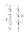
- FIG. 1 is a block diagram showing an example of the overall configuration of radio base station 10 according to the present embodiment.
- a radio base station 10 illustrated in FIG. 1 includes a scheduler 101, a transmission signal generation unit 102, an encoding / modulation unit 103, a mapping unit 104, a transmission unit 105, an antenna 106, a reception unit 107, and a control unit. 108, a channel estimation unit 109, and a demodulation / decoding unit 110 are employed.
- the radio base station 10 has a configuration of MU-MIMO (Multi-User Multiple-Input Multiple-Output) that performs communication simultaneously with a plurality of user terminals 20.
- MU-MIMO Multi-User Multiple-Input Multiple-Output
- the scheduler 101 performs scheduling (for example, resource allocation) of DL signals (DL data signals, DL control signals, DMRS, and the like). In addition, the scheduler 101 performs scheduling (for example, resource allocation) of UL signals (UL data signal, UL control signal, DMRS, and the like).
- the scheduler 101 prepares in advance a plurality of mapping patterns indicating resource elements to which the DMRS of the DL signal is mapped. For example, based on the request conditions and / or the propagation path environment of each user terminal 20, a plurality of mapping patterns are prepared. One mapping pattern is selected from the above. Plural mapping patterns are different from each other in DMRS density (for example, the arrangement interval and / or the number of DMRSs in the frequency direction and / or the time direction). Further, the mapping pattern may specify a resource element that maps DMRS across a plurality of layers.
- the requirements of the user terminal 20 and / or the propagation path environment include, for example, high channel frequency selectivity, high reception quality at the user terminal 20, short reception processing time, and movement of the user terminal 20. Including at least one of the speeds.
- the scheduler 101 selects a different mapping pattern for each user terminal 20. Note that the scheduler 101 may select the same mapping pattern for a plurality of user terminals 20.
- the scheduler 101 sets the mapping pattern of each user terminal 20 based on the selected mapping pattern. For example, when the selected mapping pattern includes DMRSs (plural DMRS ports) of a plurality of layers, the scheduler 101 assigns one or more layers (one or more DMRS ports) to each user terminal 20.
- the DMRS mapping pattern set in the user terminal 20 is referred to as a user pattern. That is, in this case, the user pattern adopts a configuration that specifies resource elements of some layers of the mapping pattern that specifies resource elements that map DMRS across a plurality of layers.
- mapping patterns prepared in advance A specific example of a plurality of mapping patterns prepared in advance and a specific example of a user pattern set based on a plurality of mapping patterns will be described later.
- Each user pattern has an associated index.
- the user terminal 20 specifies the said user pattern by notifying the user terminal 20 of the index which shows the set user pattern.
- the index indicating the user pattern may be notified to the user terminal 20 by, for example, higher layer (for example, RRC (Radio Resource Control) or MAC (Medium Access Control)) signaling, or the user terminal 20 by physical layer (PHY) signaling. May be notified.
- higher layer for example, RRC (Radio Resource Control) or MAC (Medium Access Control)
- PHY physical layer
- the user pattern may be uniquely associated with at least one of other parameters (for example, system bandwidth, carrier frequency, information on DL data signal (for example, mapping pattern of DL data signal, etc.)).
- other parameters for example, system bandwidth, carrier frequency, information on DL data signal (for example, mapping pattern of DL data signal, etc.)
- the user terminal 20 can identify the user pattern implicitly based on other parameters. Therefore, signaling for notifying a user pattern can be reduced.
- the setting of the DMRS user pattern of the DL signal is not limited to being executed by the radio base station 10 (scheduler 101), and may be executed by the user terminal 20.
- the radio base station 10 may receive an index notification indicating the set user pattern from the user terminal 20 (not shown).
- the scheduler 101 sets a user pattern for each user terminal 20 and outputs scheduling information including the user pattern to the transmission signal generation unit 102 and the mapping unit 104.
- the scheduler 101 sets the MCS (coding rate, modulation scheme, etc.) of the DL data signal and the UL data signal based on the channel quality between the radio base station 10 and the user terminal 20, for example, and MCS information Are output to the transmission signal generation unit 102 and the encoding / modulation unit 103.
- MCS is not limited to being set by the radio base station 10 and may be set by the user terminal 20.
- the radio base station 10 may receive MCS information from the user terminal 20 (not shown).
- the transmission signal generation unit 102 generates a transmission signal (including a DL data signal and a DL control signal).
- the DL control signal includes scheduling information output from the scheduler 101 (eg, DL data signal resource allocation information) or downlink control information (DCI: Downlink Control Information) including MCS information.
- DCI Downlink Control Information
- the transmission signal generation unit 102 outputs the generated transmission signal to the encoding / modulation unit 103.
- the encoding / modulation unit 103 performs encoding processing and modulation processing on the transmission signal input from the transmission signal generation unit 102 based on the MCS information input from the scheduler 101, for example. Encoding / modulating section 103 outputs the modulated transmission signal to mapping section 104.
- the mapping unit 104 maps the transmission signal input from the encoding / modulation unit 103 to a predetermined radio resource (DL resource) based on the scheduling information (for example, DL resource allocation) input from the scheduler 101. Further, the mapping unit 104 maps a reference signal (for example, DMRS) to a predetermined radio resource (DL resource) based on the scheduling information. The mapping unit 104 outputs the DL signal mapped to the radio resource to the transmission unit 105.
- DL resource for example, DL resource allocation
- the transmission unit 105 performs transmission processing such as up-conversion and amplification on the DL signal input from the mapping unit 104 and transmits a radio frequency signal (DL signal) from the antenna 106.
- transmission processing such as up-conversion and amplification on the DL signal input from the mapping unit 104 and transmits a radio frequency signal (DL signal) from the antenna 106.
- DL signal radio frequency signal
- the reception unit 107 performs reception processing such as amplification and down-conversion on the radio frequency signal (UL signal) received by the antenna 106 and outputs the UL signal to the control unit 108.
- reception processing such as amplification and down-conversion on the radio frequency signal (UL signal) received by the antenna 106 and outputs the UL signal to the control unit 108.
- the control unit 108 separates (demappings) the UL data signal and the DMRS from the UL signal input from the receiving unit 107 based on the scheduling information (UL resource allocation) input from the scheduler 101. Then, control section 108 outputs the UL data signal to demodulation / decoding section 110 and outputs DMRS to channel estimation section 109.
- the channel estimation unit 109 performs channel estimation using the DMRS of the UL signal, and outputs a channel estimation value that is an estimation result to the demodulation / decoding unit 110.
- the demodulation / decoding unit 110 performs demodulation and decoding processing on the UL data signal input from the control unit 108 based on the channel estimation value input from the channel estimation unit 109.
- the demodulation / decoding unit 110 transfers the demodulated UL data signal to an application unit (not shown).
- the application unit performs processing related to a layer higher than the physical layer or the MAC layer.
- FIG. 2 is a block diagram showing an example of the overall configuration of the user terminal 20 according to the present embodiment.
- 2 includes an antenna 201, a receiving unit 202, a control unit 203, a channel estimation unit 204, a demodulation / decoding unit 205, a transmission signal generation unit 206, an encoding / modulation unit 207, and the like.
- a configuration including a mapping unit 208 and a transmission unit 209 is employed.
- the receiving unit 202 performs reception processing such as amplification and down-conversion on the radio frequency signal (DL signal) received by the antenna 201, and outputs the DL signal to the control unit 203.
- the DL signal includes at least a DL data signal and DMRS.
- the control unit 203 separates (demappings) the DL control signal and the DMRS from the DL signal input from the receiving unit 202. Then, control section 203 outputs the DL control signal to demodulation / decoding section 205 and outputs DMRS to channel estimation section 204.
- control unit 203 controls the reception of the DMRS from the DL signal based on the user pattern notified in advance.
- control unit 203 demultiplexes the DL data signal from the DL signal based on the scheduling information (for example, DL resource allocation information) input from the demodulation / decoding unit 205, and demodulates the DL data signal. Output to the decoding unit 205.
- scheduling information for example, DL resource allocation information
- the channel estimation unit 204 performs channel estimation using the separated DMRS, and outputs a channel estimation value as an estimation result to the demodulation / decoding unit 205.
- the demodulation / decoding unit 205 demodulates the DL control signal input from the control unit 203. Further, the demodulation / decoding unit 205 performs a decoding process (for example, a blind detection process) on the demodulated DL control signal. Demodulation / decoding section 205 sends scheduling information (mapping setting including DL / UL resource allocation or DMRS user pattern) addressed to itself obtained by decoding the DL control signal to control section 203 and mapping section 208. The MCS information for the UL data signal is output to the encoding / modulation unit 207.
- a decoding process for example, a blind detection process
- Demodulation / decoding section 205 sends scheduling information (mapping setting including DL / UL resource allocation or DMRS user pattern) addressed to itself obtained by decoding the DL control signal to control section 203 and mapping section 208.
- the MCS information for the UL data signal is output to the encoding / modulation unit 207.
- the demodulation / decoding unit 205 uses the channel estimation value input from the channel estimation unit 204 based on the MCS information for the DL data signal included in the DL control signal input from the control unit 203, from the control unit 203. Demodulation and decoding are performed on the input DL data signal. Further, the demodulation / decoding unit 205 transfers the demodulated DL data signal to an application unit (not shown). The application unit performs processing related to a layer higher than the physical layer or the MAC layer.
- the transmission signal generation unit 206 generates a transmission signal (including a UL data signal or a UL control signal), and outputs the generated transmission signal to the encoding / modulation unit 207.
- the encoding / modulation unit 207 performs encoding processing and modulation processing on the transmission signal input from the transmission signal generation unit 206 based on, for example, MCS information input from the demodulation / decoding unit 205. Encoding / modulating section 207 outputs the modulated transmission signal to mapping section 208.
- mapping section 208 maps the transmission signal input from encoding / modulation section 207 to a predetermined radio resource (UL resource). . Further, the mapping unit 208 maps a reference signal (for example, DMRS) to a predetermined radio resource (UL resource) based on scheduling information (for example, mapping setting including a DMRS user pattern).
- a reference signal for example, DMRS
- UL resource a predetermined radio resource
- the transmission unit 209 performs transmission processing such as up-conversion and amplification on the UL signal (including at least the UL data signal and DMRS) input from the mapping unit 208, and transmits a radio frequency signal (UL signal) from the antenna 201. Send.
- mapping patterns a specific example of a plurality of mapping patterns and a specific example of a user pattern set based on the plurality of mapping patterns will be described.
- mapping pattern (or user pattern) with a low DMRS density thins out a part of an RE in which DMRS is arranged in a mapping pattern (or user pattern) with a high DMRS density.
- FIG. 3 is a diagram illustrating a user pattern of the first configuration example.
- FIG. 3 shows two user patterns (user pattern # 1 and user pattern # 2) as an example.
- Each user pattern indicates a DMRS mapping position in a resource unit (RU: Resource Unit) (also referred to as a resource block, a resource block pair, etc.) as a resource allocation unit.
- the RU has a configuration in which 168 resource elements (REs) are arranged in the time direction and 12 in the frequency direction.
- One RE is a radio resource area defined by one symbol and one subcarrier. That is, one RU is composed of 14 symbols and 12 subcarriers.
- the 14 symbols in the time direction of the RU are called SB1 to SB14 in order from the left.
- the 12 subcarriers in the frequency direction of the RU are called SC1 to SC12 in order from the bottom.
- a control signal channel (for example, PDCCH) is arranged in the RE of the first two symbols (that is, SB1 and SB2) of the RU.
- User pattern # 1 (user pattern of user terminal # 1) is a pattern in which DMRS of layer # 1 is arranged relatively densely in SB3, and user pattern # 2 (user pattern of user terminal # 2) is a layer
- the DMRS # 2 is a pattern arranged relatively sparser than the user pattern # 1 in SB3.
- the user pattern # 2 adopts a configuration in which a part of the RE (in FIG. 3, SC5 and SC7 of SB3) is thinned out in the user pattern # 1.
- the DMRS between different user patterns is one of code division multiplexing (CDM: Code Division Multiplexing), time division multiplexing (TDM: Time Division Division Multiplexing), and frequency division multiplexing (FDM). At least one is set to be orthogonal.
- mapping patterns to which the first configuration example is applied and user patterns set based on the mapping patterns will be described as application examples.
- FIG. 4 is a diagram illustrating a mapping pattern of the first application example.
- Each mapping pattern indicates a DMRS mapping position in an RU that is a resource allocation unit.
- the two mapping patterns include DMRS mapping positions of four layers (Layer # 1 to Layer # 4).
- a control signal channel (for example, PDCCH) is arranged in the RE of the first two symbols (that is, SB1 and SB2) of the RU.
- Mapping pattern # 1 is a pattern in which DMRS of each layer is arranged relatively densely in SB3, and mapping pattern # 2 is arranged in which parsed DMRS of each layer is relatively sparser than mapping pattern # 2 in SB3. Pattern.
- mapping pattern # 2 adopts a configuration in which a part of RE in which DMRS in mapping pattern # 1 is arranged is thinned out.
- mapping pattern # 2 employs a configuration in which the REs of SC3, SC4, SC7, SC8, SC11, and SC12 of SB3 in mapping pattern # 1 are thinned out.
- the scheduler 101 of the radio base station 10 selects one mapping pattern for each user terminal from the two mapping patterns shown in FIG. 4 based on the request conditions and / or the propagation path environment of each user terminal. For example, when the user terminal # 1 moves faster than a predetermined speed and the user terminal # 2 moves slower than a predetermined speed, the scheduler 101 sets the mapping pattern # 1 to the user terminal # 1. Select the mapping pattern # 2 for the user terminal # 2. When the user terminal # 1 is lower than the predetermined communication quality and the user terminal # 2 is higher than the predetermined communication quality, the scheduler 101 selects the mapping pattern # 1 for the user terminal # 1, and the user Mapping pattern # 2 is selected for terminal # 2.
- the scheduler 101 sets the user pattern of each user terminal by assigning one or more layers to each user terminal.
- FIG. 5 is a diagram showing a user pattern of the first application example.
- User pattern # 1 (user pattern of user terminal # 1) is composed of layers # 1 and # 3 of mapping pattern # 1
- user pattern # 2 (user pattern of user terminal # 2) is mapping pattern # 2.
- DMRSs are arranged in the same RE in layer # 1 of user pattern # 1 and layer # 2 of user pattern # 2.
- the DMRSs of different user patterns arranged in the same RE lose their orthogonality. Therefore, DMRSs arranged in the same RE of user pattern # 1 and user pattern # 2 are set to be orthogonal by Cyclic Shift (cyclic shift).
- FIG. 6 is a diagram illustrating a first example of Cyclic Shift of the first application example.
- FIG. 6 shows an example of Cyclic Shift of DMRS of layer # 1 and layer # 2 of mapping pattern # 1 and layer # 1 and layer # 2 of mapping pattern # 2 shown in FIG.
- FIG. 6 shows only SB3 in which DMRS is arranged, and other symbols are omitted.
- a to f of each RE indicate a DMRS signal series, and ⁇ 1 and ⁇ 2 indicate different phase rotation amounts. Note that the same value may be applied to a to f, or different values may be applied.
- DM DMRSs of different layers arranged in the same RE in the same mapping pattern are orthogonal by Cyclic Shift.
- the DMRS of the layer # 1 of the mapping pattern # 1 and the DMRS of the layer # 2 of the mapping pattern # 1 in FIG. 6 are orthogonal by a Cyclic Shift that applies different phase rotation amounts.
- the DMRS of layer # 1 of mapping pattern # 2 in FIG. 6 and the DMRS of layer # 2 of mapping pattern # 2 are orthogonal to each other by Cyclic Shift using different phase rotation amounts.
- the same signal series and the same phase rotation amount are applied to DMRSs of the same layer arranged in the same RE in different mapping patterns.
- DMRSs having the same value are arranged in the same RE in different mapping patterns.
- the DMRS of the same RE (SC1, SC5, and SC9) among the DMRS of layer # 1 of mapping pattern # 1 and the DMRS of layer # 2 of mapping pattern # 2 in FIG. 6 applied different phase rotation amounts.
- DMRSs of the same RE are orthogonal in layer # 1 of mapping pattern # 1 assigned as user pattern # 1 and layer # 2 of mapping pattern # 2 assigned as user pattern # 2. It is possible to suppress degradation in channel estimation accuracy in user terminals (user terminal # 1 and user terminal # 2).
- the same signal sequence and the same phase rotation amount are applied to DMRSs of the same layer arranged in the same RE in different mapping patterns.
- DMRSs of different layers arranged in the same RE in different mapping patterns can be made orthogonal to each other. Can do.
- DMRSs are arranged in the same RE in layer # 3 of mapping pattern # 1 assigned as user pattern # 1 and in layer # 4 of mapping pattern # 2 assigned as user pattern # 2. Yes.
- the same layer arranged in the same RE in different mapping patterns as in the relationship between layer # 1 and layer # 2 shown in FIG. By applying the same signal sequence and the same phase rotation amount to different DMRSs, DMRSs of different layers arranged in the same RE in different mapping patterns are orthogonal.
- the signal series and the amount of phase rotation applied to the DMRS arranged in the same RE of user pattern # 1 and user pattern # 2 in FIG. 5 are not limited to the example shown in FIG.
- a second example of a signal sequence and a phase rotation amount applied to DMRS arranged in the same RE of user pattern # 1 and user pattern # 2 in FIG. 5 will be described.
- FIG. 7 is a diagram illustrating a second example of Cyclic Shift of the first application example.
- SB3 in which DMRS is arranged is shown, and other symbols are omitted.
- a to c and x to z of each RE indicate a DMRS signal sequence
- ⁇ 1 , ⁇ 2 , ⁇ 1, and ⁇ 2 indicate different amounts of phase rotation.
- the difference between FIG. 7 and FIG. 6 is that the signal sequence and the amount of phase rotation applied to each DMRS are different.
- the same values may be applied to a to c or / and x to z, or different values may be applied.
- the same value may be applied to a and x, b and y, and c and z, or different values may be applied.
- the same value may be applied to ⁇ 1 and ⁇ 1 and ⁇ 2 and ⁇ 2 , or different values may be applied.
- the same signal series and the same phase rotation amount are applied to DMRSs of the same layer arranged in the same RE in different mapping patterns.
- DMRSs having the same value are arranged in the same RE in different mapping patterns.
- the DMRS of the same RE (SC1, SC5, and SC9) among the DMRS of layer # 1 of mapping pattern # 1 and the DMRS of layer # 2 of mapping pattern # 2 in FIG. 7 applied different phase rotation amounts.
- DMRSs of the same RE are orthogonal in layer # 1 of mapping pattern # 1 assigned as user pattern # 1 and layer # 2 of mapping pattern # 2 assigned as user pattern # 2. It is possible to suppress degradation in channel estimation accuracy in user terminals (user terminal # 1 and user terminal # 2).
- the same signal sequence and the same phase rotation amount are applied to DMRSs of the same layer arranged in the same RE in different mapping patterns.
- DMRSs of different layers arranged in the same RE in different mapping patterns can be made orthogonal to each other. Can do.
- DMRS is arranged in the same RE in layer # 3 of mapping pattern # 1 assigned as user pattern # 1 and layer # 4 of mapping pattern # 2 assigned as user pattern # 2. ing.
- the same layer arranged in the same RE in different mapping patterns as in the relationship between layer # 1 and layer # 2 shown in FIG. By applying the same signal sequence and the same phase rotation amount to different DMRSs, DMRSs of different layers arranged in the same RE in different mapping patterns are orthogonal.
- DMRS may collide with another signal (for example, another user's data channel), but in this case, a user terminal makes other signal noise. Signal processing can be performed.
- FIG. 8 is a diagram illustrating a mapping pattern of the second application example.
- FIG. 8 shows mapping pattern # 1 similar to FIG. 4 and mapping pattern # 3 different from mapping pattern # 2 of FIG.
- Mapping pattern # 3 adopts a configuration in which a part of RE in which DMRS of mapping pattern # 1 is arranged is thinned out.
- the mapping pattern # 3 adopts a configuration in which the SC3 to SC6 of SB3 and the REs of SC9 to SC12 in the mapping pattern # 1 are thinned out.
- the scheduler 101 of the radio base station 10 selects one mapping pattern for each user terminal from the two mapping patterns shown in FIG. 8 based on the request conditions and / or the propagation path environment of each user terminal. For example, when the user terminal # 1 moves faster than a predetermined speed and the user terminal # 2 moves slower than a predetermined speed, the scheduler 101 sets the mapping pattern # 1 to the user terminal # 1. Select the mapping pattern # 3 for the user terminal # 2. When the user terminal # 1 is lower than the predetermined communication quality and the user terminal # 2 is higher than the predetermined communication quality, the scheduler 101 selects the mapping pattern # 1 for the user terminal # 1, and the user Mapping pattern # 3 is selected for terminal # 2.
- the scheduler 101 sets the user pattern of each user terminal by assigning one or more layers to each user terminal.
- mapping pattern # 1 is assigned to user terminal # 1
- layer # 2 and layer # 4 of mapping pattern # 3 are assigned to user terminal # 2. To do.
- FIG. 9 is a diagram showing a user pattern of the second application example.
- User pattern # 1 (user pattern of user terminal # 1) is composed of layers # 1 and # 3 of mapping pattern # 1
- user pattern # 2 (user pattern of user terminal # 2) is mapping pattern # 3.
- the DMRS is arranged in the same RE in the layer # 1 of the user pattern # 1 and the layer # 2 of the user pattern # 2.
- the DMRSs of different user patterns arranged in the same RE lose their orthogonality. Therefore, DMRSs arranged in the same RE of user pattern # 1 and user pattern # 2 are set to be orthogonal by Cyclic Shift.
- FIG. 10 is a diagram illustrating an example of Cyclic Shift of the second application example.
- FIG. 10 illustrates an example of the Cyclic Shift of the DMRSs of the layer # 1 and the layer # 2 of the mapping pattern # 1 and the layers # 1 and # 2 of the mapping pattern # 2 illustrated in FIG.
- SB3 in which DMRS is arranged is shown, and other symbols are omitted.
- a to f of each RE indicate a DMRS signal sequence
- ⁇ 1 and ⁇ 2 indicate mutually different phase rotation amounts. Note that the same value may be applied to a to f, or different values may be applied.
- DMRSs of different layers arranged in the same RE in the same mapping pattern are orthogonal by Cyclic Shift.
- the same signal series and the same phase rotation amount are applied to DMRSs of the same layer arranged in the same RE in different mapping patterns.
- DMRSs having the same value are arranged in the same RE in different mapping patterns.
- the DMRS arranged in the SC7 of the layer # 1 of the mapping pattern # 1 and the DMRS arranged in the SC7 of the layer # 1 of the mapping pattern # 3 in FIG. ⁇ 1 ⁇ 3/6 is applied.
- the DMRS of the same RE (SC1 and SC7) among the DMRS of layer # 1 of mapping pattern # 1 and the DMRS of layer # 2 of mapping pattern # 3 in FIG. Is orthogonal.
- DMRSs of the same RE are orthogonal in layer # 1 of mapping pattern # 1 assigned as user pattern # 1 and layer # 2 of mapping pattern # 3 assigned as user pattern # 2. It is possible to suppress degradation in channel estimation accuracy in user terminals (user terminal # 1 and user terminal # 2).
- the same signal sequence and the same phase rotation amount are applied to DMRSs of the same layer arranged in the same RE in different mapping patterns.
- DMRSs of different layers arranged in the same RE in different mapping patterns can be made orthogonal to each other. Can do.
- DMRSs are arranged in the same RE in layer # 3 of mapping pattern # 1 assigned as user pattern # 1 and layer # 4 of mapping pattern # 3 assigned as user pattern # 2. Yes.
- the DMRS arranged in the same RE of layer # 3 and layer # 4 the same layer arranged in the same RE in different mapping patterns as in the relationship between layers # 1 and # 2 shown in FIG.
- DMRSs of different layers arranged in the same RE in different mapping patterns are orthogonal.
- DMRS may collide with another signal (for example, another user's data channel), and in this case, the user terminal makes other signal noise. Signal processing can be performed.
- FIG. 11 is a diagram illustrating a mapping pattern of the third application example.
- FIG. 11 shows mapping pattern # 1 similar to FIGS. 4 and 8, and mapping pattern # 4 different from mapping pattern # 2 in FIG. 4 and mapping pattern # 3 in FIG.
- Mapping pattern # 4 adopts a configuration in which a part of RE in which DMRS of mapping pattern # 1 is arranged is thinned out. In the example of FIG. 11, mapping pattern # 4 adopts a configuration in which the REs of SC7 to SC12 of SB3 in mapping pattern # 1 are thinned out.
- the scheduler 101 of the radio base station 10 selects one mapping pattern for each user terminal from the two mapping patterns shown in FIG. 11 based on the request conditions and / or the propagation path environment of each user terminal. For example, when the user terminal # 1 moves faster than a predetermined speed and the user terminal # 2 moves slower than a predetermined speed, the scheduler 101 sets the mapping pattern # 1 to the user terminal # 1. Select the mapping pattern # 4 for the user terminal # 2. When the user terminal # 1 is lower than the predetermined communication quality and the user terminal # 2 is higher than the predetermined communication quality, the scheduler 101 selects the mapping pattern # 1 for the user terminal # 1, and the user Mapping pattern # 4 is selected for terminal # 2.
- the scheduler 101 sets the user pattern of each user terminal by assigning one or more layers to each user terminal.
- FIG. 12 is a diagram showing a user pattern of the third application example.
- User pattern # 1 (user pattern of user terminal # 1) is composed of layers # 1 and # 3 of mapping pattern # 1
- user pattern # 2 (user pattern of user terminal # 2) is mapping pattern # 4.
- the DMRS is arranged in the same RE in the layer # 1 of the user pattern # 1 and the layer # 2 of the user pattern # 2.
- the DMRSs of different user patterns arranged in the same RE lose their orthogonality. Therefore, DMRSs arranged in the same RE of user pattern # 1 and user pattern # 2 are set to be orthogonal by Cyclic Shift.
- FIG. 13 is a diagram illustrating an example of Cyclic Shift of the third application example.
- FIG. 13 illustrates an example of the Cyclic Shift of the DMRSs of the layer # 1 and the layer # 2 of the mapping pattern # 1 and the layers # 1 and # 2 of the mapping pattern # 2 illustrated in FIG.
- FIG. 13 shows only SB3 in which DMRS is arranged, and other symbols are omitted.
- a to c of each RE indicate a DMRS signal series
- ⁇ 1 and ⁇ 2 indicate different phase rotation amounts. Note that the same value may be applied to a to c, or different values may be applied.
- DMRSs of different layers arranged in the same RE in the same mapping pattern are orthogonal by Cyclic Shift.
- the same signal series and the same phase rotation amount are applied to DMRSs of the same layer arranged in the same RE in different mapping patterns.
- DMRSs having the same value are arranged in the same RE in different mapping patterns.
- the DMRS of the same RE (SC1, SC3, and SC5) among the DMRS of layer # 1 of mapping pattern # 1 and the DMRS of layer # 2 of mapping pattern # 4 in FIG. 13 applied different phase rotation amounts.
- DMRSs of the same RE are orthogonal in layer # 1 of mapping pattern # 1 assigned as user pattern # 1 and layer # 2 of mapping pattern # 4 assigned as user pattern # 2. It is possible to suppress degradation in channel estimation accuracy in user terminals (user terminal # 1 and user terminal # 2).
- the same signal sequence and the same phase rotation amount are applied to DMRSs of the same layer arranged in the same RE in different mapping patterns.
- DMRSs of different layers arranged in the same RE in different mapping patterns can be made orthogonal to each other. Can do.
- DMRSs are arranged in the same RE in layer # 3 of mapping pattern # 1 assigned as user pattern # 1 and in layer # 4 of mapping pattern # 4 assigned as user pattern # 2. Yes.
- the DMRS arranged in the same RE of layer # 3 and layer # 4 the same layer arranged in the same RE in different mapping patterns as in the relationship between layer # 1 and layer # 2 shown in FIG.
- DMRSs of different layers arranged in the same RE in different mapping patterns are orthogonal.
- DMRS may collide with another signal (for example, another user's data channel).
- another signal for example, another user's data channel.
- the user terminal makes other signal noise. Signal processing can be performed.
- the orthogonal method is changed by changing the layer assigned to each user terminal.
- FIG. 14 is a diagram illustrating a user pattern of the fourth application example.
- FIG. 14 shows that the scheduler 101 assigns layer # 1 and layer # 2 of mapping pattern # 1 (see FIG. 4) to user terminal # 1, and mapping pattern # 2 (see FIG. 4) to user terminal # 2. ) Shows an example in which layer # 3 and layer # 4 are assigned.
- the user pattern # 1 (user terminal # 1 user pattern) in FIG. 14 includes the mapping pattern # 1 layer # 1 and layer # 2 shown in FIG. 4, and the user pattern # 2 (user terminal # 2).
- the user pattern) includes the layer # 3 and the layer # 4 of the mapping pattern # 2 shown in FIG.
- DMRSs are arranged on different subcarriers of the same symbol (SB3).
- SB3 subcarriers of the same symbol
- DMRSs between different user patterns are not arranged in the same RE, but are arranged in different frequencies (subcarriers), so that channel estimation in each user terminal (user terminal # 1 and user terminal # 2) Degradation of accuracy can be suppressed.
- DMRS may collide with another signal (for example, another user's data channel), but in this case, a user terminal makes other signal noise. Signal processing can be performed.
- FIG. 15 is a diagram illustrating a mapping pattern of the fifth application example.
- FIG. 15 shows mapping pattern # 5 and mapping pattern # 6.
- mapping pattern # 5 and mapping pattern # 6 include DMRS mapping positions of four layers (Layer # 1 to Layer # 4).
- a control signal channel (for example, PDCCH) is arranged in the RE of the first two symbols (that is, SB1 and SB2) of the RU.
- Mapping pattern # 5 is a pattern in which DMRS of each layer is relatively densely arranged in SB3
- mapping pattern # 6 is a pattern in which DMRS of each layer is relatively sparsely arranged in SB3 than mapping pattern # 5 It is a pattern.
- the mapping pattern # 6 adopts a configuration in which a part of the RE in which the DMRS in the mapping pattern # 5 is arranged is thinned out.
- the mapping pattern # 6 adopts a configuration in which the REs of SC5 to SC8 of SB3 in mapping pattern # 5 are thinned out.
- the scheduler 101 of the radio base station 10 selects one mapping pattern for each user terminal from the two mapping patterns shown in FIG. 15 based on the request conditions and / or the propagation path environment of each user terminal. For example, when the user terminal # 1 moves faster than the predetermined speed and the user terminal # 2 moves slower than the predetermined speed, the scheduler 101 sets the mapping pattern # 5 to the user terminal # 1. Select the mapping pattern # 6 for the user terminal # 2. When the user terminal # 1 is lower than the predetermined communication quality and the user terminal # 2 is higher than the predetermined communication quality, the scheduler 101 selects the mapping pattern # 5 for the user terminal # 1, and the user Mapping pattern # 6 is selected for terminal # 2.
- the scheduler 101 sets the user pattern of each user terminal by assigning one or more layers to each user terminal.
- mapping pattern # 5 are assigned to user terminal # 1
- layer # 2 and layer # 4 of mapping pattern # 6 are assigned to user terminal # 2. To do.
- FIG. 16 is a diagram showing a user pattern of the fifth application example.
- User pattern # 1 (user pattern of user terminal # 1) is composed of layers # 1 and # 3 of mapping pattern # 5, and user pattern # 2 (user pattern of user terminal # 2) is mapping pattern # 6. Layer # 2 and layer # 4.
- the DMRS is arranged in the same RE in the layer # 1 of the user pattern # 1 and the layer # 2 of the user pattern # 2.
- the DMRSs of different user patterns arranged in the same RE lose their orthogonality. Therefore, DMRSs arranged in the same RE of user pattern # 1 and user pattern # 2 are set to be orthogonal using an OCC sequence.
- FIG. 17 is a diagram illustrating an example of the OCC sequence of the fifth application example.
- FIG. 17 shows an example of the OCRS sequence of DMRSs of layer # 1 and layer # 2 of mapping pattern # 5 and layers # 1 and # 2 of mapping pattern # 6 shown in FIG.
- FIG. 17 shows only SB3 in which DMRS is arranged, and other symbols are omitted.
- a to c of each RE indicate DMRS signal sequences
- (+1) and ( ⁇ 1) indicate elements of an OCC sequence having a sequence length of 2, respectively. Note that the same value may be applied to a to c, or different values may be applied. Different values may be applied to a to c between different layers.
- the DMRSs of different layers arranged in the same RE in the same mapping pattern are orthogonal using the OCC sequence.
- the DMRS of layer # 1 of mapping pattern # 5 in FIG. 17 and the DMRS of layer # 2 of mapping pattern # 5 are orthogonal using an OCC sequence.
- an OCC sequence composed of (+1) and (+1) is applied to the DMRS arranged in SC1 and SC2 of layer # 1 of mapping pattern # 5, and layer # 2 of mapping pattern # 5
- the OCC sequence consisting of (+1) and ( ⁇ 1) is applied to the DMRS arranged in SC1 and SC2.
- the DMRS of layer # 1 of mapping pattern # 6 in FIG. 17 and the DMRS of layer # 2 of mapping pattern # 6 are orthogonal using an OCC sequence.
- the same signal sequence and the same OCC sequence are applied to DMRSs of the same layer arranged in the same RE in different mapping patterns.
- DMRSs having the same value are arranged in the same RE in different mapping patterns.
- the signal sequence a is applied to the DMRS arranged in SC1 and SC2 of layer # 1 of mapping pattern # 5 and the DMRS arranged in SC1 and SC2 of layer # 1 of mapping pattern # 6 in FIG. Then, an OCC sequence composed of (+1) and (+1) is applied to each signal sequence.
- the DMRS of the same RE (SC1 and SC2 and SC9 and SC10) among the DMRS of layer # 1 of mapping pattern # 5 and the DMRS of layer # 2 of mapping pattern # 6 in FIG. 17 uses an OCC sequence. Orthogonal.
- the DMRSs of the same RE are orthogonal in layer # 1 of mapping pattern # 5 assigned as user pattern # 1 and layer # 2 of mapping pattern # 6 assigned as user pattern # 2. It is possible to suppress degradation in channel estimation accuracy in user terminals (user terminal # 1 and user terminal # 2).
- the same signal sequence and the same OCC sequence are applied to DMRSs of the same layer arranged in the same RE in different mapping patterns.
- the orthogonality of DMRS between different layers of one mapping pattern can be used between mapping patterns, DMRSs of different layers arranged in the same RE in different mapping patterns can be made orthogonal to each other. Can do.
- DMRSs are arranged in the same RE in layer # 3 of mapping pattern # 5 assigned as user pattern # 1 and layer # 4 of mapping pattern # 6 assigned as user pattern # 2. Yes.
- the same layer arranged in the same RE in different mapping patterns as in the relationship between layer # 1 and layer # 2 shown in FIG. By applying the same signal sequence and the same OCC sequence to different DMRSs, DMRSs of different layers arranged in the same RE in different mapping patterns are orthogonal.
- DMRS may collide with another signal (for example, another user's data channel).
- another signal for example, another user's data channel.
- the user terminal makes other signal noise. Signal processing can be performed.
- the DMRS may be orthogonalized using another orthogonal sequence different from the OCC sequence.
- DMRSs of different layers with different mapping patterns are orthogonalized using an OCC sequence.
- DMRSs of different layers in the same user pattern are orthogonalized by FDM.
- the orthogonal method may be changed by changing the layer assigned to each user terminal.
- the orthogonal method may be changed by changing the layer assigned to each user terminal.
- FIG. 18 is a diagram illustrating a user pattern of the sixth application example.
- the scheduler 101 assigns layer # 1 and layer # 2 of mapping pattern # 5 (see FIG. 15) to user terminal # 1, and mapping pattern # 6 (see FIG. 15) to user terminal # 2.
- user pattern # 1 in FIG. 18 is composed of layer # 1 and layer # 2 of mapping pattern # 5 shown in FIG. 15, and user pattern # 2 (user terminal # 2).
- the user pattern) is composed of the layer # 3 and the layer # 4 of the mapping pattern # 6 shown in FIG.
- DMRSs are arranged on different frequencies (subcarriers) of the same symbol (SB3).
- SB3 subcarriers of the same symbol
- DMRS between different user patterns is orthogonalized by FDM.
- DMRSs of different layers within the same user pattern are orthogonal using an OCC sequence.
- the same signal sequence and the same OCC sequence are applied to DMRSs of the same layer arranged in the same RE in different mapping patterns.
- an OCC sequence is applied like layer # 1 and layer # 2 of mapping pattern # 5 shown in FIG.
- the DMRSs of different layers are orthogonalized using the OCC sequence.
- DMRSs between different user patterns are not arranged in the same RE, but are arranged in different frequencies (subcarriers), so that channel estimation in each user terminal (user terminal # 1 and user terminal # 2) Degradation of accuracy can be suppressed.
- DMRS may collide with another signal (for example, another user's data channel), but in this case, a user terminal makes other signal noise. Signal processing can be performed.
- a mapping pattern with a low DMRS density is one of two mapping patterns having different DMRS densities (for example, arrangement intervals and / or numbers of DMRSs in the frequency direction and / or time direction).
- DMRS densities for example, arrangement intervals and / or numbers of DMRSs in the frequency direction and / or time direction.
- the DMRS when viewed from a user pattern set based on a mapping pattern having a low DMRS density (user pattern # 2 described above), the DMRS is set based on a mapping pattern having a high DMRS density.
- DMRSs arranged in the same RE as the user pattern (user pattern # 1 described above) are orthogonal using an OCC sequence or Cyclic Shift.
- the DMRS arranged in the same RE as user pattern # 2 is orthogonal using an OCC sequence or Cyclic Shift.
- the DMRS arranged in the RE different from the user pattern # 2 collides with another signal (for example, another user's data channel).
- the user terminal can perform signal processing by regarding the other signal as noise.
- the first configuration example an example in which different layers (different DMRS ports) with different mapping patterns are assigned between user terminals has been described. For example, when the same layer (same DMRS port) of a different mapping pattern is allocated between user terminals, the method of the first configuration example described above may not be applied.
- the scheduler 101 selects one mapping pattern for each user terminal from mapping patterns prepared in advance, and a plurality of layers (a plurality of DMRS ports) of the selected mapping pattern
- a plurality of user patterns may be prepared in advance, and the scheduler 101 may select different user patterns between the user terminals based on the user terminal request conditions and / or the propagation path environment.
- DMRSs mapped to REs defined for each of a plurality of user patterns are set to be orthogonal to each other between different user patterns.
- the present invention is not limited to this.
- the number of REs that map the DMRS may be the same.
- the present invention is not limited to the first configuration example, and various configurations can be adopted.
- a second configuration example an example will be described in which a DMRS with a low-density mapping pattern is arranged in an RE different from a DMRS with a high-density mapping pattern.
- FIG. 19 is a diagram illustrating a user pattern of the second configuration example.
- three user patterns (user pattern # 1, user pattern # 2, and user pattern # 3) are shown as an example.
- Each user pattern indicates a DMRS mapping position in an RU that is a resource allocation unit.
- a control signal channel (for example, PDCCH) is arranged in the RE of the first two symbols (that is, SB1 and SB2) of the RU.
- User pattern # 1 (user pattern of user terminal # 1) is a pattern in which DMRS of layer # 1 is arranged relatively densely in SB3, and user pattern # 2 (user pattern of user terminal # 2) is a layer The DMRS # 2 is a pattern arranged relatively sparser than the user pattern # in SB3.
- User pattern # 3 (user pattern of user terminal # 3) is a pattern in which DMRS of layer # 3 is arranged relatively sparser than user pattern # 1 in SB4.
- user pattern # 2 arranges DMRS in the same symbol as the symbol (SB3) in which DMRS of user pattern # 1 is arranged, but has a frequency (sub frequency different from the subcarrier in which DMRS of user pattern # 1 is arranged.
- a configuration in which DMRS is arranged in the carrier) is adopted.
- DMRS of user pattern # 1 A configuration is adopted in which DMRS is arranged in a symbol (for example, SB4) different from the symbol in which is arranged.
- the DMRS of user pattern # 1 and the DMRS of user pattern # 2 are orthogonal by FDM.
- the DMRS of user pattern # 1 and the DMRS of user pattern # 3 are orthogonal by TDM.
- the DMRS of user pattern # 2 and the DMRS of user pattern # 3 are orthogonal by FDM and TDM. Therefore, it is possible to suppress deterioration in channel estimation accuracy in each user terminal (user terminal # 1 and user terminal # 2).
- DMRS may collide with another signal (for example, another user's data channel), but in this case, a user terminal makes other signal noise. Signal processing can be performed.
- the number of REs that map DMRSs is different from each other in each user pattern, but the present invention is not limited to this.
- the number of REs that map the DMRS may be the same.
- the user patterns are orthogonal to each other between the user patterns by FDM and / or TDM.
- a DMRS with a low-density mapping pattern is placed in the same RE as a DMRS arranged in a different RE from a DMRS with a high-density mapping pattern, and a part of the DMRS with a high-density mapping pattern.
- An example including a DMRS to be arranged will be described.
- FIG. 20 is a diagram illustrating a user pattern of the third configuration example.
- FIG. 20 shows two user patterns (user pattern # 1 and user pattern # 2) as an example.
- Each user pattern indicates a DMRS mapping position in an RU that is a resource allocation unit.
- a control signal channel (for example, PDCCH) is arranged in the RE of the first two symbols (that is, SB1 and SB2) of the RU.
- User pattern # 1 (user pattern of user terminal # 1) is a pattern in which DMRS of layer # 1 is arranged relatively densely in SB3, and user pattern # 2 (user pattern of user terminal # 2) is a layer
- the DMRS # 2 is a pattern arranged relatively sparser than the user pattern # in SB3.
- the DMRS of user pattern # 2 includes the DMRS arranged on the same frequency (subcarrier) (SC1 and SC7) as the subcarrier on which the DMRS of user pattern # 1 is arranged, and the DMRS of user pattern # 1.
- a configuration including DMRS arranged in subcarriers (SC4 and SC10) different from the subcarrier to be used is adopted.
- the DMRSs arranged in SC1 and SC7 of SB3 included in user pattern # 2 and user pattern # 1 are DMRSs arranged in the same RE, the method shown in the first configuration example For example, they are orthogonalized by a method using Cyclic Shift or a method using an OCC sequence.
- DMRSs arranged in SC3, SC5, SC9 and SC11 of SB3 in user pattern # 1 and DMRSs arranged in SC4 and SC10 of SB3 in user pattern # 2 are DMRSs arranged in different REs. For this reason, orthogonalization is performed by the method shown in the second configuration example, for example, FDM and / or TDM. In the example of FIG. 20, they are orthogonalized by FDM.
- the present invention is not limited to this.
- the number of REs that map the DMRS may be the same. In that case, in each user pattern, in each user pattern, some of the REs that map DMRS are different from each other, and the rest are the same. In this case, DMRSs in which part of REs to be mapped are different from each other are orthogonal to each other between user patterns by FDM and / or TDM.
- the method shown in the first configuration example (Cyclic The method is orthogonal using a method using Shift or a method using an orthogonal sequence.
- a user pattern (DMRS mapping pattern of a user terminal) is set based on one mapping pattern selected from a plurality of mapping patterns prepared in advance.
- DMRSs of a plurality of mapping patterns are set to be orthogonal to each other by at least one of FDM, CDM, and / or CDM.
- a control signal channel for example, PDCCH
- PDCCH Physical Downlink Control Channel
- the number of layers (number of DMRS ports) in the present embodiment is merely an example, and the present invention is not limited to this.
- the number of DMRS layers may be 5 or more, or 3 or less.
- the number of mapping patterns is two and the number of user terminals (the number of user patterns) is mainly described, but the present invention is not limited to this.
- the number of mapping patterns and / or the number of user terminals may be three or more.
- DMRS is mainly arranged in the third symbol (SB3) of RU
- SB3 third symbol
- the DMRS may be arranged after the fourth symbol or before the second symbol.
- Additional DMRS may be arranged.
- Additional DMRS is, for example, a DMRS arranged to improve followability to channel time fluctuations when the user terminal 20 is moving at high speed.
- the DMRS to which the present invention is applied is not particularly limited.
- the present invention may be applied only to the above-described Front-loaded DMRS, may be applied only to Additional-DMRS, or may be applied to both.
- the RU to which the present invention is applied is not particularly limited.
- the present invention may be applied to RUs at all carrier frequencies, or the present invention may be applied to RUs at some carrier frequencies.
- each functional block may be realized by one device physically and / or logically coupled, and two or more devices physically and / or logically separated may be directly and / or indirectly. (For example, wired and / or wireless) and may be realized by these plural devices.
- a wireless base station, a user terminal, etc. in an embodiment of the present invention may function as a computer that performs processing of the wireless communication method of the present invention.
- FIG. 21 is a diagram illustrating an example of a hardware configuration of a radio base station and a user terminal according to an embodiment of the present invention.
- the wireless base station 10 and the user terminal 20 described above may be physically configured as a computer device including a processor 1001, a memory 1002, a storage 1003, a communication device 1004, an input device 1005, an output device 1006, a bus 1007, and the like. Good.
- the term “apparatus” can be read as a circuit, a device, a unit, or the like.
- the hardware configurations of the radio base station 10 and the user terminal 20 may be configured to include one or a plurality of each device illustrated in the figure, or may be configured not to include some devices.
- processor 1001 may be implemented by one or more chips.
- Each function in the radio base station 10 and the user terminal 20 is obtained by reading predetermined software (program) on hardware such as the processor 1001 and the memory 1002, so that the processor 1001 performs computation and communication by the communication device 1004, or This is realized by controlling data reading and / or writing in the memory 1002 and the storage 1003.
- predetermined software program
- the processor 1001 performs computation and communication by the communication device 1004, or This is realized by controlling data reading and / or writing in the memory 1002 and the storage 1003.
- the processor 1001 controls the entire computer by operating an operating system, for example.
- the processor 1001 may be configured by a central processing unit (CPU) including an interface with peripheral devices, a control device, an arithmetic device, a register, and the like.
- CPU central processing unit
- the above-described scheduler 101, control units 108 and 203, transmission signal generation units 102 and 206, encoding / modulation units 103 and 207, mapping units 104 and 208, channel estimation units 109 and 204, demodulation / decoding units 110 and 205 Etc. may be realized by the processor 1001.
- the processor 1001 reads a program (program code), software module, or data from the storage 1003 and / or the communication device 1004 to the memory 1002, and executes various processes according to these.
- a program program code
- the scheduler 101 of the radio base station 10 may be realized by a control program stored in the memory 1002 and operated by the processor 1001, and may be realized similarly for other functional blocks.
- the above-described various processes have been described as being executed by one processor 1001, they may be executed simultaneously or sequentially by two or more processors 1001.
- the processor 1001 may be implemented by one or more chips. Note that the program may be transmitted from a network via a telecommunication line.
- the memory 1002 is a computer-readable recording medium and includes at least one of ROM (Read Only Memory), EPROM (Erasable Programmable ROM), EEPROM (Electrically Erasable Programmable ROM), RAM (Random Access Memory), and the like. May be.
- the memory 1002 may be called a register, a cache, a main memory (main storage device), or the like.
- the memory 1002 can store a program (program code), a software module, and the like that can be executed to implement the wireless communication method according to the embodiment of the present invention.
- the storage 1003 is a computer-readable recording medium such as an optical disc such as a CD-ROM (Compact Disc ROM), a hard disc drive, a flexible disc, a magneto-optical disc (eg, a compact disc, a digital versatile disc, a Blu-ray). (Registered trademark) disk, smart card, flash memory (for example, card, stick, key drive), floppy (registered trademark) disk, magnetic strip, and the like.
- the storage 1003 may be referred to as an auxiliary storage device.
- the storage medium described above may be, for example, a database, server, or other suitable medium including the memory 1002 and / or the storage 1003.
- the communication device 1004 is hardware (transmission / reception device) for performing communication between computers via a wired and / or wireless network, and is also referred to as a network device, a network controller, a network card, a communication module, or the like.
- a network device for example, the transmission units 105 and 209, the antennas 106 and 201, the reception units 107 and 202, and the like described above may be realized by the communication device 1004.
- the input device 1005 is an input device (for example, a keyboard, a mouse, a microphone, a switch, a button, a sensor, etc.) that accepts an input from the outside.
- the output device 1006 is an output device (for example, a display, a speaker, an LED lamp, etc.) that performs output to the outside.
- the input device 1005 and the output device 1006 may have an integrated configuration (for example, a touch panel).
- each device such as the processor 1001 and the memory 1002 is connected by a bus 1007 for communicating information.
- the bus 1007 may be configured with a single bus or may be configured with different buses between apparatuses.
- the radio base station 10 and the user terminal 20 include a microprocessor, a digital signal processor (DSP), an ASIC (Application Specific Integrated Circuit), a PLD (Programmable Logic Device), an FPGA (Field Programmable Gate Array), and the like. It may be configured including hardware, and a part or all of each functional block may be realized by the hardware. For example, the processor 1001 may be implemented by at least one of these hardware.
- DSP digital signal processor
- ASIC Application Specific Integrated Circuit
- PLD Programmable Logic Device
- FPGA Field Programmable Gate Array
- information notification includes physical layer signaling (for example, DCI (Downlink Control Information), UCI (Uplink Control Information)), upper layer signaling (for example, RRC (Radio Resource Control) signaling, MAC (Medium Access Control) signaling), It may be implemented by broadcast information (MIB (Master Information Block), SIB (System Information Block))), other signals, or a combination thereof.
- RRC signaling may be referred to as an RRC message, and may be, for example, an RRC connection setup message, an RRC connection reconfiguration message, or the like.
- Each aspect / embodiment described herein includes LTE (Long Term Evolution), LTE-A (LTE-Advanced), SUPER 3G, IMT-Advanced, 4G, 5G, FRA (Future Radio Access), W-CDMA.
- LTE Long Term Evolution
- LTE-A Long Term Evolution-Advanced
- SUPER 3G IMT-Advanced
- 4G 5G
- FRA Full Radio Access
- W-CDMA Wideband
- GSM registered trademark
- CDMA2000 Code Division Multiple Access 2000
- UMB User Mobile Broadband
- IEEE 802.11 Wi-Fi
- IEEE 802.16 WiMAX
- IEEE 802.20 UWB (Ultra-WideBand
- the present invention may be applied to a Bluetooth (registered trademark), a system using another appropriate system, and / or a next generation system extended based on the system.
- the specific operation assumed to be performed by the base station (radio base station) in this specification may be performed by the upper node in some cases.
- various operations performed for communication with a terminal may be performed by the base station and / or other network nodes other than the base station (e.g., It is obvious that this can be performed by MME (Mobility Management Entity) or S-GW (Serving Gateway).
- MME Mobility Management Entity
- S-GW Serving Gateway
- Information, signals, and the like can be output from the upper layer (or lower layer) to the lower layer (or upper layer). Input / output may be performed via a plurality of network nodes.
- Input / output information and the like may be stored in a specific location (for example, a memory) or may be managed by a management table. Input / output information and the like can be overwritten, updated, or additionally written. The output information or the like may be deleted. The input information or the like may be transmitted to another device.
- the determination may be performed by a value represented by 1 bit (0 or 1), may be performed by a true / false value (Boolean: true or false), or may be performed by comparing numerical values (for example, a predetermined value) Comparison with the value).
- software, instructions, etc. may be transmitted / received via a transmission medium.
- software may use websites, servers, or other devices using wired technology such as coaxial cable, fiber optic cable, twisted pair and digital subscriber line (DSL) and / or wireless technology such as infrared, wireless and microwave.
- wired technology such as coaxial cable, fiber optic cable, twisted pair and digital subscriber line (DSL) and / or wireless technology such as infrared, wireless and microwave.
- DSL digital subscriber line
- wireless technology such as infrared, wireless and microwave.
- Information, signal Information, signals, etc. described herein may be represented using any of a variety of different technologies.
- data, commands, commands, information, signals, bits, symbols, chips, etc. that may be referred to throughout the above description are voltages, currents, electromagnetic waves, magnetic fields or magnetic particles, light fields or photons, or any of these May be represented by a combination of
- the channel and / or symbol may be a signal.
- the signal may be a message.
- the component carrier (CC) may be called a carrier frequency, a cell, or the like.
- radio resource may be indicated by an index.
- a base station can accommodate one or more (eg, three) cells (also referred to as sectors). When the base station accommodates multiple cells, the entire coverage area of the base station can be partitioned into multiple smaller areas, each smaller area being a base station subsystem (eg, indoor small base station RRH: Remote Radio Head) can also provide communication services.
- the term “cell” or “sector” refers to part or all of the coverage area of a base station and / or base station subsystem that provides communication services in this coverage. Further, the terms “base station”, “eNB”, “cell”, and “sector” may be used interchangeably herein.
- a base station may also be referred to in terms such as a fixed station, NodeB, eNodeB (eNB), access point, femtocell, small cell, and the like.
- a user terminal is a mobile station, subscriber station, mobile unit, subscriber unit, wireless unit, remote unit, mobile device, wireless device, wireless communication device, remote device, mobile subscriber station, access terminal, mobile by a person skilled in the art It may also be referred to as a terminal, wireless terminal, remote terminal, handset, user agent, mobile client, client, UE (User Equipment), or some other appropriate terminology.
- determining may encompass a wide variety of actions. “Judgment” and “determination” are, for example, judgment, calculation, calculation, processing, derivation, investigating, looking up (eg, table , Searching in a database or another data structure), considering ascertaining as “determining”, “deciding”, and the like.
- determination and “determination” include receiving (for example, receiving information), transmitting (for example, transmitting information), input (input), output (output), and access. (accessing) (e.g., accessing data in a memory) may be considered as “determined” or "determined”.
- determination and “decision” means that “resolving”, “selecting”, “choosing”, “establishing”, and “comparing” are regarded as “determining” and “deciding”. May be included. In other words, “determination” and “determination” may include considering some operation as “determination” and “determination”.
- connection means any direct or indirect connection or coupling between two or more elements and It can include the presence of one or more intermediate elements between two “connected” or “coupled” elements.
- the coupling or connection between the elements may be physical, logical, or a combination thereof.
- the two elements are radio frequency by using one or more wires, cables and / or printed electrical connections, and as some non-limiting and non-inclusive examples
- electromagnetic energy such as electromagnetic energy having a wavelength in the region, microwave region, and light (both visible and invisible) region, it can be considered to be “connected” or “coupled” to each other.
- the reference signal may be abbreviated as RS (Reference Signal), and may be referred to as a pilot depending on an applied standard.
- RS Reference Signal
- the DMRS may be another corresponding name, for example, a demodulation RS or DM-RS.
- the phrase “based on” does not mean “based only on”, unless expressly specified otherwise. In other words, the phrase “based on” means both “based only on” and “based at least on.”
- the radio frame may be composed of one or a plurality of frames in the time domain.
- One or more frames in the time domain may be referred to as subframes, time units, etc.
- a subframe may further be composed of one or more slots in the time domain.
- the slot may be further configured with one or a plurality of symbols (OFDM (Orthogonal-Frequency-Division-Multiplexing) symbol, SC-FDMA (Single-Carrier-Frequency-Division-Multiple-Access) symbol, etc.) in the time domain.
- OFDM Orthogonal-Frequency-Division-Multiplexing
- SC-FDMA Single-Carrier-Frequency-Division-Multiple-Access
- the radio frame, subframe, slot, minislot, and symbol all represent time units when transmitting a signal. Radio frames, subframes, slots, minislots, and symbols may be called differently corresponding to each.
- the base station performs scheduling to allocate radio resources (frequency bandwidth, transmission power, etc. that can be used in each mobile station) to each mobile station.
- the minimum time unit of scheduling may be called TTI (Transmission Time Interval).
- one subframe may be called a TTI
- a plurality of consecutive subframes may be called a TTI
- one slot may be called a TTI
- one minislot may be called a TTI
- the resource unit is a resource allocation unit in the time domain and the frequency domain, and may include one or a plurality of continuous subcarriers in the frequency domain. In the time domain of the resource unit, it may include one or a plurality of symbols, and may have a length of 1 slot, 1 mini slot, 1 subframe, or 1 TTI. One TTI and one subframe may each be composed of one or a plurality of resource units.
- the resource unit may also be called a resource block (RB: Resource Block), a physical resource block (PRB: Physical RB), a PRB pair, an RB pair, a scheduling unit, a frequency unit, or a subband. Further, the resource unit may be composed of one or a plurality of REs.
- 1 RE may be any resource (for example, the smallest resource unit) smaller than a resource unit serving as a resource allocation unit, and is not limited to the name RE.
- the structure of the radio frame described above is merely an example, and the number of subframes included in the radio frame, the number of slots included in the subframe, the number of minislots included in the subframe, the symbols and resource blocks included in the slots, The number and the number of subcarriers included in the resource block can be variously changed.
- notification of predetermined information is not limited to explicitly performed, but is performed implicitly (for example, notification of the predetermined information is not performed). Also good.
- One embodiment of the present invention is useful for a mobile communication system.
Abstract
A user terminal (20) is provided with: a reception unit (202) which receives a downlink signal containing a demodulation reference signal; a control unit (203) which separates the demodulation reference signal from the downlink signal; and a channel estimation unit (204) which calculates a channel estimation value using the demodulation reference signal. The demodulation reference signal is mapped to a resource element defined for a transmission pattern for a user terminal, and the transmission pattern for a user terminal is selected from among a plurality of transmission patterns for user terminals, so as to be different among the user terminals, and the demodulation reference signals to be mapped to the respective resource elements defined for the plurality of user terminal transmission patterns are configured to be mutually orthogonal to one another among the different user terminal transmission patterns.
Description
本発明は、ユーザ端末、無線基地局及び無線通信方法に関する。
The present invention relates to a user terminal, a radio base station, and a radio communication method.
UMTS(Universal Mobile Telecommunication System)ネットワークにおいて、更なる高速データレート、低遅延などを目的としてロングタームエボリューション(LTE:Long Term Evolution)が仕様化された(非特許文献1)。また、LTEからの更なる広帯域化及び高速化を目的として、LTEの後継システムも検討されている。LTEの後継システムには、例えば、LTE-A(LTE-Advanced)、FRA(Future Radio Access)、5G(5th generation mobile communication system)、5G+(5G plus)、New-RAT(Radio Access Technology)などと呼ばれるものがある。
In the UMTS (Universal Mobile Telecommunication System) network, Long Term Evolution (LTE: Long Term Evolution) has been specified for the purpose of further high data rate and low delay (Non-patent Document 1). In addition, a successor system of LTE is also being studied for the purpose of further widening the bandwidth and speeding up from LTE. LTE successors include LTE-A (LTE-Advanced), FRA (Future Radio Access), 5G (5th generation mobile mobile communication system), 5G + (5G plus), New-RAT (Radio Access Technology), etc. There is what is called.
将来の無線通信システム(例えば、5G)では、低いキャリア周波数から高いキャリア周波数まで幅広い周波数をサポートすることが期待されている。例えば、低いキャリア周波数、高いキャリア高周波数などの周波数帯毎に伝搬路環境(例えば、通信品質および周波数選択性)および/または要求条件(サポートする端末の移動速度等)が大きく異なることから、将来の無線通信システムでは、伝搬路環境および/または要求条件に応じて、参照信号等の配置(マッピング)を柔軟にサポートすることが望まれる。
Future wireless communication systems (for example, 5G) are expected to support a wide range of frequencies from low carrier frequencies to high carrier frequencies. For example, the propagation path environment (for example, communication quality and frequency selectivity) and / or requirements (moving speed of a supported terminal, etc.) are greatly different for each frequency band such as a low carrier frequency and a high carrier high frequency. In such a wireless communication system, it is desired to flexibly support the arrangement (mapping) of reference signals and the like according to the propagation path environment and / or required conditions.
例えば、将来の無線通信システムでは、要求条件および/または伝搬路環境が互いに異なる端末に対して、参照信号の密度(例えば、周波数方向および/または時間方向における参照信号の配置間隔および/または数)が互いに異なる参照信号のマッピングパターンを設定することが検討されている。
For example, in a future wireless communication system, the density of reference signals (for example, the arrangement interval and / or number of reference signals in the frequency direction and / or the time direction) for terminals having different requirements and / or propagation path environments It has been studied to set reference signal mapping patterns different from each other.
しかしながら、各端末が、互いに異なるマッピングパターンに基づいてマッピングされた参照信号を受信してチャネル推定を行うと、チャネルの推定精度の劣化が生じるおそれがある。
However, when each terminal receives a reference signal mapped based on a different mapping pattern and performs channel estimation, there is a possibility that channel estimation accuracy may deteriorate.
本発明はかかる点に鑑みてなされたものであり、チャネルの推定精度の劣化を抑制し、将来の無線通信システムに適する参照信号等の構成を実現可能なユーザ端末、無線基地局及び無線通信方法を提供することを目的の一つとする。
The present invention has been made in view of the above points, and a user terminal, a radio base station, and a radio communication method capable of suppressing a deterioration in channel estimation accuracy and realizing a configuration of a reference signal and the like suitable for a future radio communication system. Is one of the purposes.
本発明の一態様に係るユーザ端末は、復調用参照信号を含む下りリンク信号を受信する受信部と、前記下りリンク信号から前記復調用参照信号を分離する制御部と、前記復調用参照信号を用いてチャネル推定値を算出するチャネル推定部と、を具備し、前記復調用参照信号は、ユーザ端末用送信パターンに規定されたリソース要素にマッピングされ、前記ユーザ端末用送信パターンは、複数のユーザ端末用送信パターンの中から、ユーザ端末間で異なるように選択され、前記複数のユーザ端末用送信パターンそれぞれに規定されたリソース要素にマッピングされる復調用参照信号は、異なるユーザ端末用送信パターン間で互いに直交する。
A user terminal according to an aspect of the present invention includes a receiving unit that receives a downlink signal including a demodulation reference signal, a control unit that separates the demodulation reference signal from the downlink signal, and the demodulation reference signal. A channel estimation unit that calculates a channel estimation value using the demodulation reference signal is mapped to a resource element defined in a user terminal transmission pattern, and the user terminal transmission pattern includes a plurality of users. The reference signal for demodulation that is selected to be different between user terminals from among the terminal transmission patterns and is mapped to the resource elements defined in each of the plurality of user terminal transmission patterns is different between the transmission patterns for different user terminals. Are orthogonal to each other.
本発明の一態様によれば、チャネルの推定精度の劣化を抑制し、将来の無線通信システムに適する参照信号等の構成を実現できる。
According to one aspect of the present invention, it is possible to suppress the deterioration of channel estimation accuracy and realize a configuration of a reference signal and the like suitable for a future wireless communication system.
以下、本発明の各実施の形態について図面を参照して詳細に説明する。
Hereinafter, embodiments of the present invention will be described in detail with reference to the drawings.
(一実施の形態)
本実施の形態に係る無線通信システムは、少なくとも、図1に示す無線基地局10、及び、図2に示すユーザ端末20を備える。ユーザ端末20は、無線基地局10に接続している。 (One embodiment)
The radio communication system according to the present embodiment includes at leastradio base station 10 shown in FIG. 1 and user terminal 20 shown in FIG. The user terminal 20 is connected to the radio base station 10.
本実施の形態に係る無線通信システムは、少なくとも、図1に示す無線基地局10、及び、図2に示すユーザ端末20を備える。ユーザ端末20は、無線基地局10に接続している。 (One embodiment)
The radio communication system according to the present embodiment includes at least
無線基地局10は、ユーザ端末20に対して、下り制御チャネル(例えば、PDCCH:Physical Downlink Control Channel)を用いて下りリンク(DL)制御信号を送信し、下りデータチャネル(例えば、下り共有チャネル:PDSCH:Physical Downlink Shared Channel)を用いてDLデータ信号及びDLデータ信号を復調するための復調用参照信号(Demodulation Reference Signal、以下、DMRS)を送信する。また、ユーザ端末20は、無線基地局10に対して、上り制御チャネル(例えば、PUCCH:Physical Uplink Control Channel)を用いて上りリンク(UL)制御信号を送信し、上りデータチャネル(例えば、上り共有チャネル:PUSCH:Physical Uplink Shared Channel)を用いてULデータ信号及びDMRSを送信する。
The radio base station 10 transmits a downlink (DL) control signal to the user terminal 20 using a downlink control channel (for example, PDCCH: PhysicalPhysDownlink Control Channel), and a downlink data channel (for example, a downlink shared channel: A DL data signal and a demodulation reference signal (Demodulation Reference Signal, hereinafter DMRS) for demodulating the DL data signal are transmitted using PDSCH: Physical Downlink Shared Channel. Also, the user terminal 20 transmits an uplink (UL) control signal to the radio base station 10 using an uplink control channel (for example, PUCCH: Physical-Uplink-Control-Channel), and an uplink data channel (for example, uplink shared) The UL data signal and DMRS are transmitted using channel: PUSCH: Physical Uplink Shared Channel).
なお、無線基地局10及びユーザ端末20が送受信する下りチャネル及び上りチャネルは、上記のPDCCH、PDSCH、PUCCH、PUSCH等に限定されず、例えば、PBCH(Physical Broadcast Channel)、RACH(Random Access Channel)等の他のチャネルでもよい。
Note that the downlink channel and uplink channel transmitted and received by the radio base station 10 and the user terminal 20 are not limited to the above PDCCH, PDSCH, PUCCH, PUSCH, and the like, for example, PBCH (Physical Broadcast Channel), RACH (Random Access Channel). Other channels may be used.
また、図1及び図2では、無線基地局10及びユーザ端末20において生成されるDL/ULの信号波形は、OFDM(Orthogonal Frequency Division Multiplexing)変調に基づく信号波形でもよく、SC-FDMA(Single Carrier-Frequency Division Multiple Access)又はDFT-S-OFDM(DFT-Spread-OFDM))に基づく信号波形でもよく、他の信号波形でもよい。図1及び図2では、信号波形を生成するための構成部(例えば、IFFT処理部、CP付加部、CP除去部、FFT処理部等)の記載を省略している。
1 and 2, the DL / UL signal waveform generated in the radio base station 10 and the user terminal 20 may be a signal waveform based on OFDM (Orthogonal (Frequency Division Multiplexing) modulation, and may be SC-FDMA (Single Carrier). -Frequency (Division-Multiple Access) or DFT-S-OFDM (DFT-Spread-OFDM)), or other signal waveforms. In FIG. 1 and FIG. 2, description of components for generating a signal waveform (for example, IFFT processing unit, CP adding unit, CP removing unit, FFT processing unit, etc.) is omitted.
<無線基地局>
図1は、本実施の形態に係る無線基地局10の全体構成の一例を示すブロック図である。図1に示す無線基地局10は、スケジューラ101と、送信信号生成部102と、符号化・変調部103と、マッピング部104と、送信部105と、アンテナ106と、受信部107と、制御部108と、チャネル推定部109と、復調・復号部110と、を含む構成を採る。無線基地局10は、複数のユーザ端末20と同時に通信を行うMU-MIMO(Multi-User Multiple-Input Multiple-Output)の構成を有する。 <Wireless base station>
FIG. 1 is a block diagram showing an example of the overall configuration ofradio base station 10 according to the present embodiment. A radio base station 10 illustrated in FIG. 1 includes a scheduler 101, a transmission signal generation unit 102, an encoding / modulation unit 103, a mapping unit 104, a transmission unit 105, an antenna 106, a reception unit 107, and a control unit. 108, a channel estimation unit 109, and a demodulation / decoding unit 110 are employed. The radio base station 10 has a configuration of MU-MIMO (Multi-User Multiple-Input Multiple-Output) that performs communication simultaneously with a plurality of user terminals 20.
図1は、本実施の形態に係る無線基地局10の全体構成の一例を示すブロック図である。図1に示す無線基地局10は、スケジューラ101と、送信信号生成部102と、符号化・変調部103と、マッピング部104と、送信部105と、アンテナ106と、受信部107と、制御部108と、チャネル推定部109と、復調・復号部110と、を含む構成を採る。無線基地局10は、複数のユーザ端末20と同時に通信を行うMU-MIMO(Multi-User Multiple-Input Multiple-Output)の構成を有する。 <Wireless base station>
FIG. 1 is a block diagram showing an example of the overall configuration of
スケジューラ101は、DL信号(DLデータ信号、DL制御信号及びDMRS等)のスケジューリング(例えば、リソース割当)を行う。また、スケジューラ101は、UL信号(ULデータ信号、UL制御信号及びDMRS等)のスケジューリング(例えば、リソース割当)を行う。
The scheduler 101 performs scheduling (for example, resource allocation) of DL signals (DL data signals, DL control signals, DMRS, and the like). In addition, the scheduler 101 performs scheduling (for example, resource allocation) of UL signals (UL data signal, UL control signal, DMRS, and the like).
スケジューリングにおいて、スケジューラ101は、DL信号のDMRSがマッピングされるリソース要素を示すマッピングパターンを予め複数用意し、例えば、各ユーザ端末20の要求条件および/または伝搬路環境に基づいて、複数のマッピングパターンの中から1つのマッピングパターンを選択する。複数用意されるマッピングパターンは、DMRSの密度(例えば、周波数方向および/または時間方向におけるDMRSの配置間隔および/または数)が互いに異なる。また、マッピングパターンは、複数のレイヤに渡ってDMRSをマッピングするリソース要素を規定しても良い。
In scheduling, the scheduler 101 prepares in advance a plurality of mapping patterns indicating resource elements to which the DMRS of the DL signal is mapped. For example, based on the request conditions and / or the propagation path environment of each user terminal 20, a plurality of mapping patterns are prepared. One mapping pattern is selected from the above. Plural mapping patterns are different from each other in DMRS density (for example, the arrangement interval and / or the number of DMRSs in the frequency direction and / or the time direction). Further, the mapping pattern may specify a resource element that maps DMRS across a plurality of layers.
ユーザ端末20の要求条件および/または伝搬路環境とは、例えば、チャネルの周波数選択性の高さ、ユーザ端末20における受信品質の高さ、受信処理時間の短さ、および、ユーザ端末20の移動速度のいずれか少なくとも1つを含む。ユーザ端末20の要求条件および/または伝搬路環境がユーザ端末20毎に異なる場合、スケジューラ101は、ユーザ端末20毎に異なるマッピングパターンを選択する。なお、スケジューラ101は、複数のユーザ端末20に対して同一のマッピングパターンを選択しても良い。
The requirements of the user terminal 20 and / or the propagation path environment include, for example, high channel frequency selectivity, high reception quality at the user terminal 20, short reception processing time, and movement of the user terminal 20. Including at least one of the speeds. When the request conditions and / or the propagation path environment of the user terminal 20 are different for each user terminal 20, the scheduler 101 selects a different mapping pattern for each user terminal 20. Note that the scheduler 101 may select the same mapping pattern for a plurality of user terminals 20.
そして、スケジューラ101は、選択したマッピングパターンに基づいて、各ユーザ端末20のマッピングパターンを設定する。例えば、選択したマッピングパターンが複数のレイヤのDMRS(複数のDMRSポート)を含む場合、スケジューラ101は、各ユーザ端末20に1つ以上のレイヤ(1つ以上のDMRSポート)を割り当てる。以下、ユーザ端末20に設定したDMRSのマッピングパターンを、ユーザパターンと記載する。つまり、この場合、ユーザパターンは、複数のレイヤに渡ってDMRSをマッピングするリソース要素を規定するマッピングパターンの一部のレイヤのリソース要素を規定する構成を採る。
Then, the scheduler 101 sets the mapping pattern of each user terminal 20 based on the selected mapping pattern. For example, when the selected mapping pattern includes DMRSs (plural DMRS ports) of a plurality of layers, the scheduler 101 assigns one or more layers (one or more DMRS ports) to each user terminal 20. Hereinafter, the DMRS mapping pattern set in the user terminal 20 is referred to as a user pattern. That is, in this case, the user pattern adopts a configuration that specifies resource elements of some layers of the mapping pattern that specifies resource elements that map DMRS across a plurality of layers.
なお、予め用意される複数のマッピングパターンの具体例および複数のマッピングパターンに基づいて設定されるユーザパターンの具体例については後述する。
A specific example of a plurality of mapping patterns prepared in advance and a specific example of a user pattern set based on a plurality of mapping patterns will be described later.
ユーザパターンには、それぞれ、インデックスが関連づけられている。そして、設定したユーザパターンを示すインデックスがユーザ端末20に通知されることにより、ユーザ端末20は、当該ユーザパターンを特定する。ユーザパターンを示すインデックスは、例えば、上位レイヤ(例えば、RRC(Radio Resource Control)又はMAC(Medium Access Control))シグナリングによってユーザ端末20へ通知されてもよく、物理レイヤ(PHY)シグナリングによってユーザ端末20へ通知されてもよい。
Each user pattern has an associated index. And the user terminal 20 specifies the said user pattern by notifying the user terminal 20 of the index which shows the set user pattern. The index indicating the user pattern may be notified to the user terminal 20 by, for example, higher layer (for example, RRC (Radio Resource Control) or MAC (Medium Access Control)) signaling, or the user terminal 20 by physical layer (PHY) signaling. May be notified.
または、ユーザパターンと、他のパラメータ(例えば、システム帯域幅、キャリア周波数、DLデータ信号に関する情報(例えば、DLデータ信号のマッピングパターン等)など)の少なくとも1つとが一意に対応付けられてもよい。この場合、ユーザ端末20は、他のパラメータに基づいて、ユーザパターンを暗黙的(implicit)に特定することができる。よって、ユーザパターンを通知するためのシグナリングを削減することができる。
Alternatively, the user pattern may be uniquely associated with at least one of other parameters (for example, system bandwidth, carrier frequency, information on DL data signal (for example, mapping pattern of DL data signal, etc.)). . In this case, the user terminal 20 can identify the user pattern implicitly based on other parameters. Therefore, signaling for notifying a user pattern can be reduced.
また、DL信号のDMRSのユーザパターンの設定は、無線基地局10(スケジューラ101)によって実行される場合に限定されず、ユーザ端末20によって実行されても良い。ユーザ端末20がユーザパターンを設定する場合、無線基地局10は、ユーザ端末20から、設定したユーザパターンを示すインデックスの通知を受信すれば良い(図示せず)。
Also, the setting of the DMRS user pattern of the DL signal is not limited to being executed by the radio base station 10 (scheduler 101), and may be executed by the user terminal 20. When the user terminal 20 sets a user pattern, the radio base station 10 may receive an index notification indicating the set user pattern from the user terminal 20 (not shown).
スケジューラ101は、ユーザ端末20毎にユーザパターンを設定し、ユーザパターンを含むスケジューリング情報を送信信号生成部102及びマッピング部104に出力する。
The scheduler 101 sets a user pattern for each user terminal 20 and outputs scheduling information including the user pattern to the transmission signal generation unit 102 and the mapping unit 104.
また、スケジューラ101は、例えば、無線基地局10とユーザ端末20との間のチャネル品質に基づいて、DLデータ信号及びULデータ信号のMCS(符号化率、変調方式等)を設定し、MCS情報を送信信号生成部102及び符号化・変調部103へ出力する。なお、MCSは、無線基地局10が設定する場合に限定されず、ユーザ端末20が設定してもよい。ユーザ端末20がMCSを設定する場合、無線基地局10は、ユーザ端末20からMCS情報を受信すればよい(図示せず)。
Further, the scheduler 101 sets the MCS (coding rate, modulation scheme, etc.) of the DL data signal and the UL data signal based on the channel quality between the radio base station 10 and the user terminal 20, for example, and MCS information Are output to the transmission signal generation unit 102 and the encoding / modulation unit 103. Note that the MCS is not limited to being set by the radio base station 10 and may be set by the user terminal 20. When the user terminal 20 sets MCS, the radio base station 10 may receive MCS information from the user terminal 20 (not shown).
送信信号生成部102は、送信信号(DLデータ信号、DL制御信号を含む)を生成する。例えば、DL制御信号には、スケジューラ101から出力されたスケジューリング情報(例えば、DLデータ信号のリソース割当情報)又はMCS情報を含む下り制御情報(DCI:Downlink Control Information)が含まれる。送信信号生成部102は、生成した送信信号を符号化・変調部103に出力する。
The transmission signal generation unit 102 generates a transmission signal (including a DL data signal and a DL control signal). For example, the DL control signal includes scheduling information output from the scheduler 101 (eg, DL data signal resource allocation information) or downlink control information (DCI: Downlink Control Information) including MCS information. The transmission signal generation unit 102 outputs the generated transmission signal to the encoding / modulation unit 103.
符号化・変調部103は、例えば、スケジューラ101から入力されるMCS情報に基づいて、送信信号生成部102から入力される送信信号に対して、符号化処理及び変調処理を行う。符号化・変調部103は、変調後の送信信号をマッピング部104に出力する。
The encoding / modulation unit 103 performs encoding processing and modulation processing on the transmission signal input from the transmission signal generation unit 102 based on the MCS information input from the scheduler 101, for example. Encoding / modulating section 103 outputs the modulated transmission signal to mapping section 104.
マッピング部104は、スケジューラ101から入力されるスケジューリング情報(例えば、DLのリソース割当)に基づいて、符号化・変調部103から入力される送信信号を所定の無線リソース(DLリソース)にマッピングする。また、マッピング部104は、スケジューリング情報に基づいて、参照信号(例えば、DMRS)を所定の無線リソース(DLリソース)にマッピングする。マッピング部104は、無線リソースにマッピングされたDL信号を送信部105に出力する。
The mapping unit 104 maps the transmission signal input from the encoding / modulation unit 103 to a predetermined radio resource (DL resource) based on the scheduling information (for example, DL resource allocation) input from the scheduler 101. Further, the mapping unit 104 maps a reference signal (for example, DMRS) to a predetermined radio resource (DL resource) based on the scheduling information. The mapping unit 104 outputs the DL signal mapped to the radio resource to the transmission unit 105.
送信部105は、マッピング部104から入力されるDL信号に対して、アップコンバート、増幅等の送信処理を行い、無線周波数信号(DL信号)をアンテナ106から送信する。
The transmission unit 105 performs transmission processing such as up-conversion and amplification on the DL signal input from the mapping unit 104 and transmits a radio frequency signal (DL signal) from the antenna 106.
受信部107は、アンテナ106で受信された無線周波数信号(UL信号)に対して、増幅、ダウンコンバート等の受信処理を行い、UL信号を制御部108に出力する。
The reception unit 107 performs reception processing such as amplification and down-conversion on the radio frequency signal (UL signal) received by the antenna 106 and outputs the UL signal to the control unit 108.
制御部108は、スケジューラ101から入力されるスケジューリング情報(ULのリソース割当)に基づいて、受信部107から入力されるUL信号からULデータ信号及びDMRSを分離(デマッピング)する。そして、制御部108は、ULデータ信号を復調・復号部110に出力しDMRSをチャネル推定部109に出力する。
The control unit 108 separates (demappings) the UL data signal and the DMRS from the UL signal input from the receiving unit 107 based on the scheduling information (UL resource allocation) input from the scheduler 101. Then, control section 108 outputs the UL data signal to demodulation / decoding section 110 and outputs DMRS to channel estimation section 109.
チャネル推定部109は、UL信号のDMRSを用いてチャネル推定を行い、推定結果であるチャネル推定値を復調・復号部110に出力する。
The channel estimation unit 109 performs channel estimation using the DMRS of the UL signal, and outputs a channel estimation value that is an estimation result to the demodulation / decoding unit 110.
復調・復号部110は、チャネル推定部109から入力されるチャネル推定値に基づいて、制御部108から入力されるULデータ信号に対して復調及び復号処理を行う。復調・復号部110は、復調後のULデータ信号を、アプリケーション部(図示せず)に転送する。なお、アプリケーション部は、物理レイヤ又はMACレイヤより上位のレイヤに関する処理などを行う。
The demodulation / decoding unit 110 performs demodulation and decoding processing on the UL data signal input from the control unit 108 based on the channel estimation value input from the channel estimation unit 109. The demodulation / decoding unit 110 transfers the demodulated UL data signal to an application unit (not shown). The application unit performs processing related to a layer higher than the physical layer or the MAC layer.
<ユーザ端末>
図2は、本実施の形態に係るユーザ端末20の全体構成の一例を示すブロック図である。図2に示すユーザ端末20は、アンテナ201と、受信部202と、制御部203と、チャネル推定部204と、復調・復号部205と、送信信号生成部206と、符号化・変調部207と、マッピング部208と、送信部209と、を含む構成を採る。 <User terminal>
FIG. 2 is a block diagram showing an example of the overall configuration of theuser terminal 20 according to the present embodiment. 2 includes an antenna 201, a receiving unit 202, a control unit 203, a channel estimation unit 204, a demodulation / decoding unit 205, a transmission signal generation unit 206, an encoding / modulation unit 207, and the like. , A configuration including a mapping unit 208 and a transmission unit 209 is employed.
図2は、本実施の形態に係るユーザ端末20の全体構成の一例を示すブロック図である。図2に示すユーザ端末20は、アンテナ201と、受信部202と、制御部203と、チャネル推定部204と、復調・復号部205と、送信信号生成部206と、符号化・変調部207と、マッピング部208と、送信部209と、を含む構成を採る。 <User terminal>
FIG. 2 is a block diagram showing an example of the overall configuration of the
受信部202は、アンテナ201で受信された無線周波数信号(DL信号)に対して、増幅、ダウンコンバート等の受信処理を行い、DL信号を制御部203に出力する。DL信号には、少なくとも、DLデータ信号及びDMRSが含まれる。
The receiving unit 202 performs reception processing such as amplification and down-conversion on the radio frequency signal (DL signal) received by the antenna 201, and outputs the DL signal to the control unit 203. The DL signal includes at least a DL data signal and DMRS.
制御部203は、受信部202から入力されるDL信号からDL制御信号及びDMRSを分離(デマッピング)する。そして、制御部203は、DL制御信号を復調・復号部205に出力し、DMRSをチャネル推定部204に出力する。
The control unit 203 separates (demappings) the DL control signal and the DMRS from the DL signal input from the receiving unit 202. Then, control section 203 outputs the DL control signal to demodulation / decoding section 205 and outputs DMRS to channel estimation section 204.
その際、制御部203は、予め通知されたユーザパターンに基づいて、DL信号からDMRSの受信を制御する。
At that time, the control unit 203 controls the reception of the DMRS from the DL signal based on the user pattern notified in advance.
また、制御部203は、復調・復号部205から入力されるスケジューリング情報(例えば、DLのリソース割当情報)に基づいて、DL信号からDLデータ信号を分離(デマッピング)し、DLデータ信号を復調・復号部205に出力する。
Further, the control unit 203 demultiplexes the DL data signal from the DL signal based on the scheduling information (for example, DL resource allocation information) input from the demodulation / decoding unit 205, and demodulates the DL data signal. Output to the decoding unit 205.
チャネル推定部204は、分離したDMRSを用いてチャネル推定を行い、推定結果であるチャネル推定値を復調・復号部205に出力する。
The channel estimation unit 204 performs channel estimation using the separated DMRS, and outputs a channel estimation value as an estimation result to the demodulation / decoding unit 205.
復調・復号部205は、制御部203から入力されるDL制御信号を復調する。また、復調・復号部205は、復調後のDL制御信号に対して復号処理(例えば、ブラインド検出処理)を行う。復調・復号部205は、DL制御信号を復号することによって得られた自機宛てのスケジューリング情報(DL/ULのリソース割当又はDMRSのユーザパターンを含むマッピング設定)を制御部203及びマッピング部208に出力し、ULデータ信号に対するMCS情報を符号化・変調部207へ出力する。
The demodulation / decoding unit 205 demodulates the DL control signal input from the control unit 203. Further, the demodulation / decoding unit 205 performs a decoding process (for example, a blind detection process) on the demodulated DL control signal. Demodulation / decoding section 205 sends scheduling information (mapping setting including DL / UL resource allocation or DMRS user pattern) addressed to itself obtained by decoding the DL control signal to control section 203 and mapping section 208. The MCS information for the UL data signal is output to the encoding / modulation unit 207.
また、復調・復号部205は、制御部203から入力されるDL制御信号に含まれるDLデータ信号に対するMCS情報に基づいて、チャネル推定部204から入力されるチャネル推定値を用いて制御部203から入力されるDLデータ信号に対して復調及び復号処理を行う。また、復調・復号部205は、復調後のDLデータ信号をアプリケーション部(図示せず)に転送する。なお、アプリケーション部は、物理レイヤ又はMACレイヤより上位のレイヤに関する処理などを行う。
Further, the demodulation / decoding unit 205 uses the channel estimation value input from the channel estimation unit 204 based on the MCS information for the DL data signal included in the DL control signal input from the control unit 203, from the control unit 203. Demodulation and decoding are performed on the input DL data signal. Further, the demodulation / decoding unit 205 transfers the demodulated DL data signal to an application unit (not shown). The application unit performs processing related to a layer higher than the physical layer or the MAC layer.
送信信号生成部206は、送信信号(ULデータ信号又はUL制御信号を含む)を生成し、生成した送信信号を符号化・変調部207に出力する。
The transmission signal generation unit 206 generates a transmission signal (including a UL data signal or a UL control signal), and outputs the generated transmission signal to the encoding / modulation unit 207.
符号化・変調部207は、例えば、復調・復号部205から入力されるMCS情報に基づいて、送信信号生成部206から入力される送信信号に対して、符号化処理及び変調処理を行う。符号化・変調部207は、変調後の送信信号をマッピング部208に出力する。
The encoding / modulation unit 207 performs encoding processing and modulation processing on the transmission signal input from the transmission signal generation unit 206 based on, for example, MCS information input from the demodulation / decoding unit 205. Encoding / modulating section 207 outputs the modulated transmission signal to mapping section 208.
マッピング部208は、復調・復号部205から入力されるスケジューリング情報(ULのリソース割当)に基づいて、符号化・変調部207から入力される送信信号を所定の無線リソース(ULリソース)にマッピングする。また、マッピング部208は、スケジューリング情報(例えば、DMRSのユーザパターンを含むマッピング設定)に基づいて、参照信号(例えば、DMRS)を所定の無線リソース(ULリソース)にマッピングする。
Based on the scheduling information (UL resource allocation) input from demodulation / decoding section 205, mapping section 208 maps the transmission signal input from encoding / modulation section 207 to a predetermined radio resource (UL resource). . Further, the mapping unit 208 maps a reference signal (for example, DMRS) to a predetermined radio resource (UL resource) based on scheduling information (for example, mapping setting including a DMRS user pattern).
送信部209は、マッピング部208から入力されるUL信号(少なくともULデータ信号及びDMRSを含む)に対して、アップコンバート、増幅等の送信処理を行い、無線周波数信号(UL信号)をアンテナ201から送信する。
The transmission unit 209 performs transmission processing such as up-conversion and amplification on the UL signal (including at least the UL data signal and DMRS) input from the mapping unit 208, and transmits a radio frequency signal (UL signal) from the antenna 201. Send.
次に、複数のマッピングパターンの具体例および複数のマッピングパターンに基づいて設定されるユーザパターンの具体例について説明する。
Next, a specific example of a plurality of mapping patterns and a specific example of a user pattern set based on the plurality of mapping patterns will be described.
はじめに、第1の構成例として、DMRSの密度の低いマッピングパターン(またはユーザパターン)が、DMRSの密度の高いマッピングパターン(またはユーザパターン)におけるDMRSの配置されるREの一部を間引いた構成を採る例について説明する。
First, as a first configuration example, a mapping pattern (or user pattern) with a low DMRS density thins out a part of an RE in which DMRS is arranged in a mapping pattern (or user pattern) with a high DMRS density. An example will be described.
なお、以下の説明において、複数のユーザ端末20を区別するために、ユーザ端末#1、ユーザ端末#2などと記載し、各ユーザ端末20に設定されるユーザパターンを区別するために、ユーザパターン#1、#2などと記載する。
In the following description, in order to distinguish between a plurality of user terminals 20, user terminal # 1, user terminal # 2, etc. are described, and in order to distinguish user patterns set in each user terminal 20, user patterns Described as # 1, # 2, etc.
<第1の構成例>
図3は、第1の構成例のユーザパターンを示す図である。図3には、2つのユーザパターン(ユーザパターン#1およびユーザパターン#2)が一例として示される。各ユーザパターンは、リソース割り当て単位となるリソースユニット(RU:Resource Unit)(リソースブロック、リソースブロックペア等とも呼ばれる)におけるDMRSのマッピング位置を示す。RUは、168個のリソース要素(RE:Resource Element)が時間方向に14個、周波数方向に12個並んだ構成を有する。1REは、1シンボルと1サブキャリアとにより定義される無線リソース領域である。つまり、1つのRUは、14シンボルと12サブキャリアとにより構成される。 <First configuration example>
FIG. 3 is a diagram illustrating a user pattern of the first configuration example. FIG. 3 shows two user patterns (user pattern # 1 and user pattern # 2) as an example. Each user pattern indicates a DMRS mapping position in a resource unit (RU: Resource Unit) (also referred to as a resource block, a resource block pair, etc.) as a resource allocation unit. The RU has a configuration in which 168 resource elements (REs) are arranged in the time direction and 12 in the frequency direction. One RE is a radio resource area defined by one symbol and one subcarrier. That is, one RU is composed of 14 symbols and 12 subcarriers.
図3は、第1の構成例のユーザパターンを示す図である。図3には、2つのユーザパターン(ユーザパターン#1およびユーザパターン#2)が一例として示される。各ユーザパターンは、リソース割り当て単位となるリソースユニット(RU:Resource Unit)(リソースブロック、リソースブロックペア等とも呼ばれる)におけるDMRSのマッピング位置を示す。RUは、168個のリソース要素(RE:Resource Element)が時間方向に14個、周波数方向に12個並んだ構成を有する。1REは、1シンボルと1サブキャリアとにより定義される無線リソース領域である。つまり、1つのRUは、14シンボルと12サブキャリアとにより構成される。 <First configuration example>
FIG. 3 is a diagram illustrating a user pattern of the first configuration example. FIG. 3 shows two user patterns (
なお、以下の説明では、RUの時間方向の14シンボルを左から順にSB1~SB14と呼ぶ。また、RUの周波数方向の12サブキャリアを下から順にSC1~SC12と呼ぶ。
In the following description, the 14 symbols in the time direction of the RU are called SB1 to SB14 in order from the left. The 12 subcarriers in the frequency direction of the RU are called SC1 to SC12 in order from the bottom.
RUの先頭の2シンボル(つまり、SB1およびSB2)のREには、制御信号チャネル(例えば、PDCCH)が配置される。
A control signal channel (for example, PDCCH) is arranged in the RE of the first two symbols (that is, SB1 and SB2) of the RU.
ユーザパターン#1(ユーザ端末#1のユーザパターン)は、レイヤ#1のDMRSがSB3において比較的密に配置されるパターンであり、ユーザパターン#2(ユーザ端末#2のユーザパターン)は、レイヤ#2のDMRSがSB3において、ユーザパターン#1よりも比較的疎に配置されるパターンである。
User pattern # 1 (user pattern of user terminal # 1) is a pattern in which DMRS of layer # 1 is arranged relatively densely in SB3, and user pattern # 2 (user pattern of user terminal # 2) is a layer The DMRS # 2 is a pattern arranged relatively sparser than the user pattern # 1 in SB3.
そして、ユーザパターン#2は、ユーザパターン#1におけるDMRSが配置されるREの一部(図3では、SB3のSC5およびSC7)を間引いた構成を採る。このような場合において、異なるユーザパターンの間のDMRSは、符号分割多重(CDM:Code Division Multiplexing)、時分割多重(TDM:Time Division Multiplexing)および周波数分割多重(FDM:Frequency Division Multiplexing)のいずれか少なくとも1つにより直交するように設定する。
The user pattern # 2 adopts a configuration in which a part of the RE (in FIG. 3, SC5 and SC7 of SB3) is thinned out in the user pattern # 1. In such a case, the DMRS between different user patterns is one of code division multiplexing (CDM: Code Division Multiplexing), time division multiplexing (TDM: Time Division Division Multiplexing), and frequency division multiplexing (FDM). At least one is set to be orthogonal.
以下では、第1の構成例が適用される、複数のマッピングパターンとマッピングパターンに基づいて設定されるユーザパターンを、適用例として説明する。
Hereinafter, a plurality of mapping patterns to which the first configuration example is applied and user patterns set based on the mapping patterns will be described as application examples.
<第1の適用例>
図4は、第1の適用例のマッピングパターンを示す図である。各マッピングパターンは、リソース割り当て単位となるRUにおけるDMRSのマッピング位置を示す。また、2つのマッピングパターン(マッピングパターン#1およびマッピングパターン#2)には、4つのレイヤ(Layer #1~Layer #4)のDMRSのマッピング位置が含まれる。 <First application example>
FIG. 4 is a diagram illustrating a mapping pattern of the first application example. Each mapping pattern indicates a DMRS mapping position in an RU that is a resource allocation unit. The two mapping patterns (mapping pattern # 1 and mapping pattern # 2) include DMRS mapping positions of four layers (Layer # 1 to Layer # 4).
図4は、第1の適用例のマッピングパターンを示す図である。各マッピングパターンは、リソース割り当て単位となるRUにおけるDMRSのマッピング位置を示す。また、2つのマッピングパターン(マッピングパターン#1およびマッピングパターン#2)には、4つのレイヤ(Layer #1~Layer #4)のDMRSのマッピング位置が含まれる。 <First application example>
FIG. 4 is a diagram illustrating a mapping pattern of the first application example. Each mapping pattern indicates a DMRS mapping position in an RU that is a resource allocation unit. The two mapping patterns (
RUの先頭の2シンボル(つまり、SB1およびSB2)のREには、制御信号チャネル(例えば、PDCCH)が配置される。
A control signal channel (for example, PDCCH) is arranged in the RE of the first two symbols (that is, SB1 and SB2) of the RU.
マッピングパターン#1は、各レイヤのDMRSがSB3において比較的密に配置されるパターンであり、マッピングパターン#2は、各レイヤのDMRSがSB3において、マッピングパターン#2よりも比較的疎に配置されるパターンである。
Mapping pattern # 1 is a pattern in which DMRS of each layer is arranged relatively densely in SB3, and mapping pattern # 2 is arranged in which parsed DMRS of each layer is relatively sparser than mapping pattern # 2 in SB3. Pattern.
そして、マッピングパターン#2は、マッピングパターン#1におけるDMRSが配置されるREの一部を間引いた構成を採る。図4の例では、マッピングパターン#2は、マッピングパターン#1におけるSB3のSC3、SC4、SC7、SC8、SC11およびSC12のREを間引いた構成を採る。
Further, mapping pattern # 2 adopts a configuration in which a part of RE in which DMRS in mapping pattern # 1 is arranged is thinned out. In the example of FIG. 4, mapping pattern # 2 employs a configuration in which the REs of SC3, SC4, SC7, SC8, SC11, and SC12 of SB3 in mapping pattern # 1 are thinned out.
例えば、無線基地局10のスケジューラ101は、図4に示す2つのマッピングパターンから、各ユーザ端末の要求条件および/または伝搬路環境に基づいて、ユーザ端末毎に1つのマッピングパターンを選択する。例えば、ユーザ端末#1が所定の速度よりも高速に移動し、ユーザ端末#2が所定の速度よりも低速に移動する場合、スケジューラ101は、ユーザ端末#1に対して、マッピングパターン#1を選択し、ユーザ端末#2に対して、マッピングパターン#2を選択する。また、ユーザ端末#1が所定の通信品質よりも低く、ユーザ端末#2が所定の通信品質よりも高い場合、スケジューラ101は、ユーザ端末#1に対して、マッピングパターン#1を選択し、ユーザ端末#2に対して、マッピングパターン#2を選択する。
For example, the scheduler 101 of the radio base station 10 selects one mapping pattern for each user terminal from the two mapping patterns shown in FIG. 4 based on the request conditions and / or the propagation path environment of each user terminal. For example, when the user terminal # 1 moves faster than a predetermined speed and the user terminal # 2 moves slower than a predetermined speed, the scheduler 101 sets the mapping pattern # 1 to the user terminal # 1. Select the mapping pattern # 2 for the user terminal # 2. When the user terminal # 1 is lower than the predetermined communication quality and the user terminal # 2 is higher than the predetermined communication quality, the scheduler 101 selects the mapping pattern # 1 for the user terminal # 1, and the user Mapping pattern # 2 is selected for terminal # 2.
そして、スケジューラ101は、各ユーザ端末に対して1つ以上のレイヤを割り当てることにより、各ユーザ端末のユーザパターンを設定する。
And the scheduler 101 sets the user pattern of each user terminal by assigning one or more layers to each user terminal.
以下では、ユーザ端末#1に対してマッピングパターン#1のレイヤ#1およびレイヤ#3を割り当てて、ユーザ端末#2に対してマッピングパターン#2のレイヤ#2およびレイヤ#4を割り当てる例を説明する。
In the following, an example is described in which layer # 1 and layer # 3 of mapping pattern # 1 are assigned to user terminal # 1, and layer # 2 and layer # 4 of mapping pattern # 2 are assigned to user terminal # 2. To do.
図5は、第1の適用例のユーザパターンを示す図である。ユーザパターン#1(ユーザ端末#1のユーザパターン)は、マッピングパターン#1のレイヤ#1およびレイヤ#3から構成され、ユーザパターン#2(ユーザ端末#2のユーザパターン)は、マッピングパターン#2のレイヤ#2およびレイヤ#4から構成される。
FIG. 5 is a diagram showing a user pattern of the first application example. User pattern # 1 (user pattern of user terminal # 1) is composed of layers # 1 and # 3 of mapping pattern # 1, and user pattern # 2 (user pattern of user terminal # 2) is mapping pattern # 2. Layer # 2 and layer # 4.
これらの例において、ユーザパターン#1のレイヤ#1とユーザパターン#2のレイヤ#2において、同一のREにDMRSが配置されている。同一のREに配置される異なるユーザパターンのDMRSは、直交性が崩れてしまう。そこで、ユーザパターン#1とユーザパターン#2の同一のREに配置されるDMRSは、Cyclic Shift(巡回シフト)により直交するように設定される。
In these examples, DMRSs are arranged in the same RE in layer # 1 of user pattern # 1 and layer # 2 of user pattern # 2. The DMRSs of different user patterns arranged in the same RE lose their orthogonality. Therefore, DMRSs arranged in the same RE of user pattern # 1 and user pattern # 2 are set to be orthogonal by Cyclic Shift (cyclic shift).
図6は、第1の適用例のCyclic Shiftの第1の例を示す図である。図6には、図4に示したマッピングパターン#1のレイヤ#1およびレイヤ#2、ならびに、マッピングパターン#2のレイヤ#1およびレイヤ#2のDMRSのCyclic Shiftの例が示されている。なお、図6には、DMRSが配置されるSB3のみが示され、他のシンボルは省略されている。
FIG. 6 is a diagram illustrating a first example of Cyclic Shift of the first application example. FIG. 6 shows an example of Cyclic Shift of DMRS of layer # 1 and layer # 2 of mapping pattern # 1 and layer # 1 and layer # 2 of mapping pattern # 2 shown in FIG. FIG. 6 shows only SB3 in which DMRS is arranged, and other symbols are omitted.
図6における、各REのa~fは、DMRSの信号系列を示し、θ1およびθ2は、互いに異なる位相回転量を示している。なお、a~fは同一の値を適用しても良いし、異なる値を適用しても良い。
In FIG. 6, a to f of each RE indicate a DMRS signal series, and θ 1 and θ 2 indicate different phase rotation amounts. Note that the same value may be applied to a to f, or different values may be applied.
同一のマッピングパターンにおいて同一のREに配置される異なるレイヤのDMRSは、Cyclic Shiftにより直交する。
DM DMRSs of different layers arranged in the same RE in the same mapping pattern are orthogonal by Cyclic Shift.
例えば、図6のマッピングパターン#1のレイヤ#1のDMRSとマッピングパターン#1のレイヤ#2のDMRSとは、互いに異なる位相回転量を適用したCyclic Shiftにより直交する。同様に、図6のマッピングパターン#2のレイヤ#1のDMRSとマッピングパターン#2のレイヤ#2のDMRSとは、互いに異なる位相回転量を適用したCyclic Shiftにより直交する。
For example, the DMRS of the layer # 1 of the mapping pattern # 1 and the DMRS of the layer # 2 of the mapping pattern # 1 in FIG. 6 are orthogonal by a Cyclic Shift that applies different phase rotation amounts. Similarly, the DMRS of layer # 1 of mapping pattern # 2 in FIG. 6 and the DMRS of layer # 2 of mapping pattern # 2 are orthogonal to each other by Cyclic Shift using different phase rotation amounts.
また、異なるマッピングパターンにおいて同一のREに配置される同じレイヤのDMRSに対して、同一の信号系列および同一の位相回転量を適用する。同一の信号系列および同一の位相回転量を適用することにより、異なるマッピングパターンにおいて同一のREには、互いに同一の値を有するDMRSが配置される。
Also, the same signal series and the same phase rotation amount are applied to DMRSs of the same layer arranged in the same RE in different mapping patterns. By applying the same signal sequence and the same phase rotation amount, DMRSs having the same value are arranged in the same RE in different mapping patterns.
例えば、図6のマッピングパターン#1のレイヤ#1のSC5に配置されるDMRSとマッピングパターン#2のレイヤ#1のSC5に配置されるDMRSには、同一の信号系列cと同一の位相回転量θ1×2/6が適用される。
For example, in the DMRS arranged in SC5 of layer # 1 of mapping pattern # 1 and the DMRS arranged in SC5 of layer # 1 of mapping pattern # 2 in FIG. θ 1 × 2/6 is applied.
このように、異なるマッピングパターンにおいて同一のREに配置される同じレイヤのDMRSに対して同一の信号系列および同一の位相回転量を適用することにより、異なるマッピングパターンにおいて同一のREに配置される異なるレイヤのDMRSは直交する。
In this way, by applying the same signal sequence and the same phase rotation amount to DMRSs of the same layer arranged in the same RE in different mapping patterns, different arrangements in the same RE in different mapping patterns The DMRS of the layers are orthogonal.
例えば、図6のマッピングパターン#1のレイヤ#1のDMRSとマッピングパターン#2のレイヤ#2のDMRSのうち、同一のRE(SC1、SC5およびSC9)のDMRSは、異なる位相回転量を適用したCyclic Shiftにより直交する。
For example, the DMRS of the same RE (SC1, SC5, and SC9) among the DMRS of layer # 1 of mapping pattern # 1 and the DMRS of layer # 2 of mapping pattern # 2 in FIG. 6 applied different phase rotation amounts. Orthogonal by Cyclic Shift.
この構成により、ユーザパターン#1として割り当てられたマッピングパターン#1のレイヤ#1とユーザパターン#2として割り当てられたマッピングパターン#2のレイヤ#2において、同一のREのDMRSが直交するため、各ユーザ端末(ユーザ端末#1およびユーザ端末#2)におけるチャネル推定精度の劣化を抑制できる。
With this configuration, DMRSs of the same RE are orthogonal in layer # 1 of mapping pattern # 1 assigned as user pattern # 1 and layer # 2 of mapping pattern # 2 assigned as user pattern # 2. It is possible to suppress degradation in channel estimation accuracy in user terminals (user terminal # 1 and user terminal # 2).
また、この構成では、異なるマッピングパターンにおいて同一のREに配置される同じレイヤのDMRSに対して同一の信号系列および同一の位相回転量を適用する。これにより、1つのマッピングパターンの異なるレイヤ間のDMRSの直交性を、マッピングパターン間で利用することができるため、異なるマッピングパターンにおいて同一のREに配置される、異なるレイヤのDMRSを互いに直交させることができる。
In this configuration, the same signal sequence and the same phase rotation amount are applied to DMRSs of the same layer arranged in the same RE in different mapping patterns. Thereby, since the orthogonality of DMRS between different layers of one mapping pattern can be used between mapping patterns, DMRSs of different layers arranged in the same RE in different mapping patterns can be made orthogonal to each other. Can do.
なお、図5では、ユーザパターン#1として割り当てられたマッピングパターン#1のレイヤ#3とユーザパターン#2として割り当てられたマッピングパターン#2のレイヤ#4において、同一のREにDMRSが配置されている。このレイヤ#3とレイヤ#4の同一のREに配置されるDMRSについても、図6に示すレイヤ#1とレイヤ#2の関係と同様に、異なるマッピングパターンにおいて同一のREに配置される同じレイヤのDMRSに対して同一の信号系列および同一の位相回転量を適用することにより、異なるマッピングパターンにおいて同一のREに配置される異なるレイヤのDMRSが直交する。
In FIG. 5, DMRSs are arranged in the same RE in layer # 3 of mapping pattern # 1 assigned as user pattern # 1 and in layer # 4 of mapping pattern # 2 assigned as user pattern # 2. Yes. As for the DMRS arranged in the same RE of layer # 3 and layer # 4, the same layer arranged in the same RE in different mapping patterns as in the relationship between layer # 1 and layer # 2 shown in FIG. By applying the same signal sequence and the same phase rotation amount to different DMRSs, DMRSs of different layers arranged in the same RE in different mapping patterns are orthogonal.
なお、図5のユーザパターン#1とユーザパターン#2の同一のREに配置されるDMRSに適用される信号系列および位相回転量は、図6に示す例に限定されない。次に、図5のユーザパターン#1とユーザパターン#2の同一のREに配置されるDMRSに適用される信号系列および位相回転量の第2の例について説明する。
Note that the signal series and the amount of phase rotation applied to the DMRS arranged in the same RE of user pattern # 1 and user pattern # 2 in FIG. 5 are not limited to the example shown in FIG. Next, a second example of a signal sequence and a phase rotation amount applied to DMRS arranged in the same RE of user pattern # 1 and user pattern # 2 in FIG. 5 will be described.
図7は、第1の適用例のCyclic Shiftの第2の例を示す図である。図7には、図6と同様に、図4に示したマッピングパターン#1のレイヤ#1およびレイヤ#2、ならびに、マッピングパターン#2のレイヤ#1およびレイヤ#2のDMRSのCyclic Shiftの例が示されている。なお、図7には、DMRSが配置されるSB3のみが示され、他のシンボルは省略されている。
FIG. 7 is a diagram illustrating a second example of Cyclic Shift of the first application example. In FIG. 7, as in FIG. 6, DMRS Cyclic Shift examples of mapping pattern # 1 of layer # 1 and layer # 2 and mapping pattern # 2 of layer # 1 and layer # 2 shown in FIG. It is shown. In FIG. 7, only SB3 in which DMRS is arranged is shown, and other symbols are omitted.
図7における、各REのa~cおよびx~zは、DMRSの信号系列を示し、θ1、θ2、φ1およびφ2は、互いに異なる位相回転量を示している。図7と図6との相違点は、各DMRSに適用される信号系列および位相回転量が異なる点である。なお、a~cまたは/およびx~zは同一の値を適用しても良いし、異なる値を適用しても良い。また、aとx、bとy、cとzも同一の値を適用しても良いし、異なる値を適用しても良い。また、θ1とφ1、θ2とφ2も同一の値を適用しても良いし、異なる値を適用しても良い。
In FIG. 7, a to c and x to z of each RE indicate a DMRS signal sequence, and θ 1 , θ 2 , φ 1, and φ 2 indicate different amounts of phase rotation. The difference between FIG. 7 and FIG. 6 is that the signal sequence and the amount of phase rotation applied to each DMRS are different. The same values may be applied to a to c or / and x to z, or different values may be applied. Moreover, the same value may be applied to a and x, b and y, and c and z, or different values may be applied. Also, the same value may be applied to θ 1 and φ 1 and θ 2 and φ 2 , or different values may be applied.
そして、図7においても、異なるマッピングパターンにおいて同一のREに配置される同じレイヤのDMRSに対して、同一の信号系列および同一の位相回転量を適用する。同一の信号系列および同一の位相回転量を適用することにより、異なるマッピングパターンにおいて同一のREには、互いに同一の値を有するDMRSが配置される。
Also in FIG. 7, the same signal series and the same phase rotation amount are applied to DMRSs of the same layer arranged in the same RE in different mapping patterns. By applying the same signal sequence and the same phase rotation amount, DMRSs having the same value are arranged in the same RE in different mapping patterns.
例えば、図7のマッピングパターン#1のレイヤ#1のSC5に配置されるDMRSとマッピングパターン#2のレイヤ#1のSC5に配置されるDMRSには、同一の信号系列bと同一の位相回転量θ1×1/3が適用される。
For example, in the DMRS arranged in the SC5 of the layer # 1 of the mapping pattern # 1 and the DMRS arranged in the SC5 of the layer # 1 of the mapping pattern # 2 in FIG. θ 1 × 1/3 is applied.
このように、異なるマッピングパターンにおいて同一のREに配置される同じレイヤのDMRSに対して同一の信号系列および位相回転量を適用することにより、異なるマッピングパターンにおいて同一のREに配置される異なるレイヤのDMRSは直交する。
In this way, by applying the same signal sequence and phase rotation amount to DMRSs of the same layer arranged in the same RE in different mapping patterns, different layers arranged in the same RE in different mapping patterns DMRS is orthogonal.
例えば、図7のマッピングパターン#1のレイヤ#1のDMRSとマッピングパターン#2のレイヤ#2のDMRSのうち、同一のRE(SC1、SC5およびSC9)のDMRSは、異なる位相回転量を適用したCyclic Shiftにより直交する。
For example, the DMRS of the same RE (SC1, SC5, and SC9) among the DMRS of layer # 1 of mapping pattern # 1 and the DMRS of layer # 2 of mapping pattern # 2 in FIG. 7 applied different phase rotation amounts. Orthogonal by Cyclic Shift.
この構成により、ユーザパターン#1として割り当てられたマッピングパターン#1のレイヤ#1とユーザパターン#2として割り当てられたマッピングパターン#2のレイヤ#2において、同一のREのDMRSが直交するため、各ユーザ端末(ユーザ端末#1およびユーザ端末#2)におけるチャネル推定精度の劣化を抑制できる。
With this configuration, DMRSs of the same RE are orthogonal in layer # 1 of mapping pattern # 1 assigned as user pattern # 1 and layer # 2 of mapping pattern # 2 assigned as user pattern # 2. It is possible to suppress degradation in channel estimation accuracy in user terminals (user terminal # 1 and user terminal # 2).
また、この構成では、異なるマッピングパターンにおいて同一のREに配置される同じレイヤのDMRSに対して同一の信号系列および同一の位相回転量を適用する。これにより、1つのマッピングパターンの異なるレイヤ間のDMRSの直交性を、マッピングパターン間で利用することができるため、異なるマッピングパターンにおいて同一のREに配置される、異なるレイヤのDMRSを互いに直交させることができる。
In this configuration, the same signal sequence and the same phase rotation amount are applied to DMRSs of the same layer arranged in the same RE in different mapping patterns. Thereby, since the orthogonality of DMRS between different layers of one mapping pattern can be used between mapping patterns, DMRSs of different layers arranged in the same RE in different mapping patterns can be made orthogonal to each other. Can do.
なお、図5では、ユーザパターン#1として割り当てられたマッピングパターン#1のレイヤ#3とユーザパターン#2として割り当てられたマッピングパターン#2のレイヤ#4とが、同一のREにDMRSが配置されている。このレイヤ#3とレイヤ#4の同一のREに配置されるDMRSについても、図7に示すレイヤ#1とレイヤ#2の関係と同様に、異なるマッピングパターンにおいて同一のREに配置される同じレイヤのDMRSに対して同一の信号系列および同一の位相回転量を適用することにより、異なるマッピングパターンにおいて同一のREに配置される異なるレイヤのDMRSが直交する。
In FIG. 5, DMRS is arranged in the same RE in layer # 3 of mapping pattern # 1 assigned as user pattern # 1 and layer # 4 of mapping pattern # 2 assigned as user pattern # 2. ing. As for the DMRS arranged in the same RE of layer # 3 and layer # 4, the same layer arranged in the same RE in different mapping patterns as in the relationship between layer # 1 and layer # 2 shown in FIG. By applying the same signal sequence and the same phase rotation amount to different DMRSs, DMRSs of different layers arranged in the same RE in different mapping patterns are orthogonal.
なお、図5の各ユーザパターンが設定された場合、DMRSが、他の信号(例えば、他のユーザのデータチャネル)と衝突する場合があるが、この場合、ユーザ端末は、他の信号を雑音と見なして信号処理を行うことができる。
In addition, when each user pattern of FIG. 5 is set, DMRS may collide with another signal (for example, another user's data channel), but in this case, a user terminal makes other signal noise. Signal processing can be performed.
次に、図4とは異なるマッピングパターンに基づいてユーザパターンを設定する例を、第2の適用例として説明する。
Next, an example in which a user pattern is set based on a mapping pattern different from that in FIG. 4 will be described as a second application example.
<第2の適用例>
図8は、第2の適用例のマッピングパターンを示す図である。図8には、図4と同様のマッピングパターン#1と、図4のマッピングパターン#2と異なるマッピングパターン#3が示される。 <Second application example>
FIG. 8 is a diagram illustrating a mapping pattern of the second application example. FIG. 8 showsmapping pattern # 1 similar to FIG. 4 and mapping pattern # 3 different from mapping pattern # 2 of FIG.
図8は、第2の適用例のマッピングパターンを示す図である。図8には、図4と同様のマッピングパターン#1と、図4のマッピングパターン#2と異なるマッピングパターン#3が示される。 <Second application example>
FIG. 8 is a diagram illustrating a mapping pattern of the second application example. FIG. 8 shows
マッピングパターン#3は、マッピングパターン#1のDMRSが配置されるREの一部を間引いた構成を採る。図8の例では、マッピングパターン#3は、マッピングパターン#1におけるSB3のSC3~SC6およびSC9~SC12のREを間引いた構成を採る。
Mapping pattern # 3 adopts a configuration in which a part of RE in which DMRS of mapping pattern # 1 is arranged is thinned out. In the example of FIG. 8, the mapping pattern # 3 adopts a configuration in which the SC3 to SC6 of SB3 and the REs of SC9 to SC12 in the mapping pattern # 1 are thinned out.
例えば、無線基地局10のスケジューラ101は、図8に示す2つのマッピングパターンから、各ユーザ端末の要求条件および/または伝搬路環境に基づいて、ユーザ端末毎に1つのマッピングパターンを選択する。例えば、ユーザ端末#1が所定の速度よりも高速に移動し、ユーザ端末#2が所定の速度よりも低速に移動する場合、スケジューラ101は、ユーザ端末#1に対して、マッピングパターン#1を選択し、ユーザ端末#2に対して、マッピングパターン#3を選択する。また、ユーザ端末#1が所定の通信品質よりも低く、ユーザ端末#2が所定の通信品質よりも高い場合、スケジューラ101は、ユーザ端末#1に対して、マッピングパターン#1を選択し、ユーザ端末#2に対して、マッピングパターン#3を選択する。
For example, the scheduler 101 of the radio base station 10 selects one mapping pattern for each user terminal from the two mapping patterns shown in FIG. 8 based on the request conditions and / or the propagation path environment of each user terminal. For example, when the user terminal # 1 moves faster than a predetermined speed and the user terminal # 2 moves slower than a predetermined speed, the scheduler 101 sets the mapping pattern # 1 to the user terminal # 1. Select the mapping pattern # 3 for the user terminal # 2. When the user terminal # 1 is lower than the predetermined communication quality and the user terminal # 2 is higher than the predetermined communication quality, the scheduler 101 selects the mapping pattern # 1 for the user terminal # 1, and the user Mapping pattern # 3 is selected for terminal # 2.
そして、スケジューラ101は、各ユーザ端末に対して1つ以上のレイヤを割り当てることにより、各ユーザ端末のユーザパターンを設定する。
And the scheduler 101 sets the user pattern of each user terminal by assigning one or more layers to each user terminal.
以下では、ユーザ端末#1に対してマッピングパターン#1のレイヤ#1およびレイヤ#3を割り当てて、ユーザ端末#2に対してマッピングパターン#3のレイヤ#2およびレイヤ#4を割り当てる例を説明する。
Hereinafter, an example will be described in which layer # 1 and layer # 3 of mapping pattern # 1 are assigned to user terminal # 1, and layer # 2 and layer # 4 of mapping pattern # 3 are assigned to user terminal # 2. To do.
図9は、第2の適用例のユーザパターンを示す図である。ユーザパターン#1(ユーザ端末#1のユーザパターン)は、マッピングパターン#1のレイヤ#1およびレイヤ#3から構成され、ユーザパターン#2(ユーザ端末#2のユーザパターン)は、マッピングパターン#3のレイヤ#2およびレイヤ#4から構成される。
FIG. 9 is a diagram showing a user pattern of the second application example. User pattern # 1 (user pattern of user terminal # 1) is composed of layers # 1 and # 3 of mapping pattern # 1, and user pattern # 2 (user pattern of user terminal # 2) is mapping pattern # 3. Layer # 2 and layer # 4.
これらの例において、ユーザパターン#1のレイヤ#1とユーザパターン#2のレイヤ#2とは、同一のREにDMRSが配置されている。同一のREに配置される異なるユーザパターンのDMRSは、直交性が崩れてしまう。そこで、ユーザパターン#1とユーザパターン#2の同一のREに配置されるDMRSは、Cyclic Shiftにより直交するように設定される。
In these examples, the DMRS is arranged in the same RE in the layer # 1 of the user pattern # 1 and the layer # 2 of the user pattern # 2. The DMRSs of different user patterns arranged in the same RE lose their orthogonality. Therefore, DMRSs arranged in the same RE of user pattern # 1 and user pattern # 2 are set to be orthogonal by Cyclic Shift.
図10は、第2の適用例のCyclic Shiftの一例を示す図である。図10には、図8に示したマッピングパターン#1のレイヤ#1およびレイヤ#2、ならびに、マッピングパターン#2のレイヤ#1およびレイヤ#2のDMRSのCyclic Shiftの例が示されている。なお、図10には、DMRSが配置されるSB3のみが示され、他のシンボルは省略されている。
FIG. 10 is a diagram illustrating an example of Cyclic Shift of the second application example. FIG. 10 illustrates an example of the Cyclic Shift of the DMRSs of the layer # 1 and the layer # 2 of the mapping pattern # 1 and the layers # 1 and # 2 of the mapping pattern # 2 illustrated in FIG. In FIG. 10, only SB3 in which DMRS is arranged is shown, and other symbols are omitted.
図10における、各REのa~fは、DMRSの信号系列を示し、θ1およびθ2は、互いに異なる位相回転量を示している。なお、a~fは同一の値を適用しても良いし、異なる値を適用しても良い。
In FIG. 10, a to f of each RE indicate a DMRS signal sequence, and θ 1 and θ 2 indicate mutually different phase rotation amounts. Note that the same value may be applied to a to f, or different values may be applied.
図10の例では、図6と同様に、同一のマッピングパターンにおいて同一のREに配置される異なるレイヤのDMRSは、Cyclic Shiftにより直交する。
In the example of FIG. 10, as in FIG. 6, DMRSs of different layers arranged in the same RE in the same mapping pattern are orthogonal by Cyclic Shift.
そして、異なるマッピングパターンにおいて同一のREに配置される同じレイヤのDMRSに対して、同一の信号系列および同一の位相回転量を適用する。同一の信号系列および同一の位相回転量を適用することにより、異なるマッピングパターンにおいて同一のREには、互いに同一の値を有するDMRSが配置される。
Then, the same signal series and the same phase rotation amount are applied to DMRSs of the same layer arranged in the same RE in different mapping patterns. By applying the same signal sequence and the same phase rotation amount, DMRSs having the same value are arranged in the same RE in different mapping patterns.
例えば、図10のマッピングパターン#1のレイヤ#1のSC7に配置されるDMRSとマッピングパターン#3のレイヤ#1のSC7に配置されるDMRSには、同一の信号系列dと同一の位相回転量θ1×3/6が適用される。
For example, the DMRS arranged in the SC7 of the layer # 1 of the mapping pattern # 1 and the DMRS arranged in the SC7 of the layer # 1 of the mapping pattern # 3 in FIG. θ 1 × 3/6 is applied.
このように、異なるマッピングパターンにおいて同一のREに配置される同じレイヤのDMRSに対して同一の信号系列および同一の位相回転量を適用することにより、異なるマッピングパターンにおいて同一のREに配置される異なるレイヤのDMRSは直交する。
In this way, by applying the same signal sequence and the same phase rotation amount to DMRSs of the same layer arranged in the same RE in different mapping patterns, different arrangements in the same RE in different mapping patterns The DMRS of the layers are orthogonal.
例えば、図10のマッピングパターン#1のレイヤ#1のDMRSとマッピングパターン#3のレイヤ#2のDMRSのうち、同一のRE(SC1およびSC7)のDMRSは、異なる位相回転量を適用したCyclic Shiftにより直交する。
For example, the DMRS of the same RE (SC1 and SC7) among the DMRS of layer # 1 of mapping pattern # 1 and the DMRS of layer # 2 of mapping pattern # 3 in FIG. Is orthogonal.
この構成により、ユーザパターン#1として割り当てられたマッピングパターン#1のレイヤ#1とユーザパターン#2として割り当てられたマッピングパターン#3のレイヤ#2において、同一のREのDMRSが直交するため、各ユーザ端末(ユーザ端末#1およびユーザ端末#2)におけるチャネル推定精度の劣化を抑制できる。
With this configuration, DMRSs of the same RE are orthogonal in layer # 1 of mapping pattern # 1 assigned as user pattern # 1 and layer # 2 of mapping pattern # 3 assigned as user pattern # 2. It is possible to suppress degradation in channel estimation accuracy in user terminals (user terminal # 1 and user terminal # 2).
また、この構成では、異なるマッピングパターンにおいて同一のREに配置される同じレイヤのDMRSに対して同一の信号系列および同一の位相回転量を適用する。これにより、1つのマッピングパターンの異なるレイヤ間のDMRSの直交性を、マッピングパターン間で利用することができるため、異なるマッピングパターンにおいて同一のREに配置される、異なるレイヤのDMRSを互いに直交させることができる。
In this configuration, the same signal sequence and the same phase rotation amount are applied to DMRSs of the same layer arranged in the same RE in different mapping patterns. Thereby, since the orthogonality of DMRS between different layers of one mapping pattern can be used between mapping patterns, DMRSs of different layers arranged in the same RE in different mapping patterns can be made orthogonal to each other. Can do.
なお、図9では、ユーザパターン#1として割り当てられたマッピングパターン#1のレイヤ#3とユーザパターン#2として割り当てられたマッピングパターン#3のレイヤ#4において、同一のREにDMRSが配置されている。このレイヤ#3とレイヤ#4の同一のREに配置されるDMRSについても、図10に示すレイヤ#1とレイヤ#2の関係と同様に、異なるマッピングパターンにおいて同一のREに配置される同じレイヤのDMRSに対して同一の信号系列および同一の位相回転量を適用することにより、異なるマッピングパターンにおいて同一のREに配置される異なるレイヤのDMRSが直交する。
In FIG. 9, DMRSs are arranged in the same RE in layer # 3 of mapping pattern # 1 assigned as user pattern # 1 and layer # 4 of mapping pattern # 3 assigned as user pattern # 2. Yes. As for the DMRS arranged in the same RE of layer # 3 and layer # 4, the same layer arranged in the same RE in different mapping patterns as in the relationship between layers # 1 and # 2 shown in FIG. By applying the same signal sequence and the same phase rotation amount to different DMRSs, DMRSs of different layers arranged in the same RE in different mapping patterns are orthogonal.
また、図9の各ユーザパターンが設定された場合、DMRSが、他の信号(例えば、他のユーザのデータチャネル)と衝突する場合があるが、この場合、ユーザ端末は、他の信号を雑音と見なして信号処理を行うことができる。
In addition, when each user pattern in FIG. 9 is set, DMRS may collide with another signal (for example, another user's data channel), and in this case, the user terminal makes other signal noise. Signal processing can be performed.
次に、図4、図8とは異なるマッピングパターンに基づいてユーザパターンを設定する例を、第3の適用例として説明する。
Next, an example in which a user pattern is set based on a mapping pattern different from those in FIGS. 4 and 8 will be described as a third application example.
<第3の適用例>
図11は、第3の適用例のマッピングパターンを示す図である。図11には、図4、図8と同様のマッピングパターン#1と、図4のマッピングパターン#2および図8のマッピングパターン#3と異なるマッピングパターン#4が示される。 <Third application example>
FIG. 11 is a diagram illustrating a mapping pattern of the third application example. FIG. 11 showsmapping pattern # 1 similar to FIGS. 4 and 8, and mapping pattern # 4 different from mapping pattern # 2 in FIG. 4 and mapping pattern # 3 in FIG.
図11は、第3の適用例のマッピングパターンを示す図である。図11には、図4、図8と同様のマッピングパターン#1と、図4のマッピングパターン#2および図8のマッピングパターン#3と異なるマッピングパターン#4が示される。 <Third application example>
FIG. 11 is a diagram illustrating a mapping pattern of the third application example. FIG. 11 shows
マッピングパターン#4は、マッピングパターン#1のDMRSが配置されるREの一部を間引いた構成を採る。図11の例では、マッピングパターン#4は、マッピングパターン#1におけるSB3のSC7~SC12のREを間引いた構成を採る。
Mapping pattern # 4 adopts a configuration in which a part of RE in which DMRS of mapping pattern # 1 is arranged is thinned out. In the example of FIG. 11, mapping pattern # 4 adopts a configuration in which the REs of SC7 to SC12 of SB3 in mapping pattern # 1 are thinned out.
例えば、無線基地局10のスケジューラ101は、図11に示す2つのマッピングパターンから、各ユーザ端末の要求条件および/または伝搬路環境に基づいて、ユーザ端末毎に1つのマッピングパターンを選択する。例えば、ユーザ端末#1が所定の速度よりも高速に移動し、ユーザ端末#2が所定の速度よりも低速に移動する場合、スケジューラ101は、ユーザ端末#1に対して、マッピングパターン#1を選択し、ユーザ端末#2に対して、マッピングパターン#4を選択する。また、ユーザ端末#1が所定の通信品質よりも低く、ユーザ端末#2が所定の通信品質よりも高い場合、スケジューラ101は、ユーザ端末#1に対して、マッピングパターン#1を選択し、ユーザ端末#2に対して、マッピングパターン#4を選択する。
For example, the scheduler 101 of the radio base station 10 selects one mapping pattern for each user terminal from the two mapping patterns shown in FIG. 11 based on the request conditions and / or the propagation path environment of each user terminal. For example, when the user terminal # 1 moves faster than a predetermined speed and the user terminal # 2 moves slower than a predetermined speed, the scheduler 101 sets the mapping pattern # 1 to the user terminal # 1. Select the mapping pattern # 4 for the user terminal # 2. When the user terminal # 1 is lower than the predetermined communication quality and the user terminal # 2 is higher than the predetermined communication quality, the scheduler 101 selects the mapping pattern # 1 for the user terminal # 1, and the user Mapping pattern # 4 is selected for terminal # 2.
そして、スケジューラ101は、各ユーザ端末に対して1つ以上のレイヤを割り当てることにより、各ユーザ端末のユーザパターンを設定する。
And the scheduler 101 sets the user pattern of each user terminal by assigning one or more layers to each user terminal.
以下では、ユーザ端末#1に対してマッピングパターン#1のレイヤ#1およびレイヤ#3を割り当てて、ユーザ端末#2に対してマッピングパターン#4のレイヤ#2およびレイヤ#4を割り当てる例を説明する。
In the following, an example is described in which layer # 1 and layer # 3 of mapping pattern # 1 are assigned to user terminal # 1, and layer # 2 and layer # 4 of mapping pattern # 4 are assigned to user terminal # 2. To do.
図12は、第3の適用例のユーザパターンを示す図である。ユーザパターン#1(ユーザ端末#1のユーザパターン)は、マッピングパターン#1のレイヤ#1およびレイヤ#3から構成され、ユーザパターン#2(ユーザ端末#2のユーザパターン)は、マッピングパターン#4のレイヤ#2およびレイヤ#4から構成される。
FIG. 12 is a diagram showing a user pattern of the third application example. User pattern # 1 (user pattern of user terminal # 1) is composed of layers # 1 and # 3 of mapping pattern # 1, and user pattern # 2 (user pattern of user terminal # 2) is mapping pattern # 4. Layer # 2 and layer # 4.
これらの例において、ユーザパターン#1のレイヤ#1とユーザパターン#2のレイヤ#2とは、同一のREにDMRSが配置されている。同一のREに配置される異なるユーザパターンのDMRSは、直交性が崩れてしまう。そこで、ユーザパターン#1とユーザパターン#2の同一のREに配置されるDMRSは、Cyclic Shiftにより直交するように設定される。
In these examples, the DMRS is arranged in the same RE in the layer # 1 of the user pattern # 1 and the layer # 2 of the user pattern # 2. The DMRSs of different user patterns arranged in the same RE lose their orthogonality. Therefore, DMRSs arranged in the same RE of user pattern # 1 and user pattern # 2 are set to be orthogonal by Cyclic Shift.
図13は、第3の適用例のCyclic Shiftの一例を示す図である。図13には、図11に示したマッピングパターン#1のレイヤ#1およびレイヤ#2、ならびに、マッピングパターン#2のレイヤ#1およびレイヤ#2のDMRSのCyclic Shiftの例が示されている。なお、図13には、DMRSが配置されるSB3のみが示され、他のシンボルは省略されている。
FIG. 13 is a diagram illustrating an example of Cyclic Shift of the third application example. FIG. 13 illustrates an example of the Cyclic Shift of the DMRSs of the layer # 1 and the layer # 2 of the mapping pattern # 1 and the layers # 1 and # 2 of the mapping pattern # 2 illustrated in FIG. FIG. 13 shows only SB3 in which DMRS is arranged, and other symbols are omitted.
図13における、各REのa~cは、DMRSの信号系列を示し、θ1およびθ2は、互いに異なる位相回転量を示している。なお、a~cは同一の値を適用しても良いし、異なる値を適用しても良い。
In FIG. 13, a to c of each RE indicate a DMRS signal series, and θ 1 and θ 2 indicate different phase rotation amounts. Note that the same value may be applied to a to c, or different values may be applied.
図13の例では、図6と同様に、同一のマッピングパターンにおいて同一のREに配置される異なるレイヤのDMRSは、Cyclic Shiftにより直交する。
In the example of FIG. 13, as in FIG. 6, DMRSs of different layers arranged in the same RE in the same mapping pattern are orthogonal by Cyclic Shift.
そして、異なるマッピングパターンにおいて同一のREに配置される同じレイヤのDMRSに対して、同一の信号系列および同一の位相回転量を適用する。同一の信号系列および同一の位相回転量を適用することにより、異なるマッピングパターンにおいて同一のREには、互いに同一の値を有するDMRSが配置される。
Then, the same signal series and the same phase rotation amount are applied to DMRSs of the same layer arranged in the same RE in different mapping patterns. By applying the same signal sequence and the same phase rotation amount, DMRSs having the same value are arranged in the same RE in different mapping patterns.
例えば、図13のマッピングパターン#1のレイヤ#1のSC3に配置されるDMRSとマッピングパターン#4のレイヤ#1のSC3に配置されるDMRSには、同一の信号系列bと同一の位相回転量θ1×1/3が適用される。
For example, in the DMRS arranged in the SC3 of the layer # 1 of the mapping pattern # 1 and the DMRS arranged in the SC3 of the layer # 1 of the mapping pattern # 4 in FIG. θ 1 × 1/3 is applied.
このように、異なるマッピングパターンにおいて同一のREに配置される同じレイヤのDMRSに対して同一の信号系列および同一の位相回転量を適用することにより、異なるマッピングパターンにおいて同一のREに配置される異なるレイヤのDMRSは直交する。
In this way, by applying the same signal sequence and the same phase rotation amount to DMRSs of the same layer arranged in the same RE in different mapping patterns, different arrangements in the same RE in different mapping patterns The DMRS of the layers are orthogonal.
例えば、図13のマッピングパターン#1のレイヤ#1のDMRSとマッピングパターン#4のレイヤ#2のDMRSのうち、同一のRE(SC1、SC3およびSC5)のDMRSは、異なる位相回転量を適用したCyclic Shiftにより直交する。
For example, the DMRS of the same RE (SC1, SC3, and SC5) among the DMRS of layer # 1 of mapping pattern # 1 and the DMRS of layer # 2 of mapping pattern # 4 in FIG. 13 applied different phase rotation amounts. Orthogonal by Cyclic Shift.
この構成により、ユーザパターン#1として割り当てられたマッピングパターン#1のレイヤ#1とユーザパターン#2として割り当てられたマッピングパターン#4のレイヤ#2において、同一のREのDMRSが直交するため、各ユーザ端末(ユーザ端末#1およびユーザ端末#2)におけるチャネル推定精度の劣化を抑制できる。
With this configuration, DMRSs of the same RE are orthogonal in layer # 1 of mapping pattern # 1 assigned as user pattern # 1 and layer # 2 of mapping pattern # 4 assigned as user pattern # 2. It is possible to suppress degradation in channel estimation accuracy in user terminals (user terminal # 1 and user terminal # 2).
また、この構成では、異なるマッピングパターンにおいて同一のREに配置される同じレイヤのDMRSに対して同一の信号系列および同一の位相回転量を適用する。これにより、1つのマッピングパターンの異なるレイヤ間のDMRSの直交性を、マッピングパターン間で利用することができるため、異なるマッピングパターンにおいて同一のREに配置される、異なるレイヤのDMRSを互いに直交させることができる。
In this configuration, the same signal sequence and the same phase rotation amount are applied to DMRSs of the same layer arranged in the same RE in different mapping patterns. Thereby, since the orthogonality of DMRS between different layers of one mapping pattern can be used between mapping patterns, DMRSs of different layers arranged in the same RE in different mapping patterns can be made orthogonal to each other. Can do.
なお、図12では、ユーザパターン#1として割り当てられたマッピングパターン#1のレイヤ#3とユーザパターン#2として割り当てられたマッピングパターン#4のレイヤ#4において、同一のREにDMRSが配置されている。このレイヤ#3とレイヤ#4の同一のREに配置されるDMRSについても、図13に示すレイヤ#1とレイヤ#2の関係と同様に、異なるマッピングパターンにおいて同一のREに配置される同じレイヤのDMRSに対して同一の信号系列および位相回転量を適用することにより、異なるマッピングパターンにおいて同一のREに配置される異なるレイヤのDMRSが直交する。
In FIG. 12, DMRSs are arranged in the same RE in layer # 3 of mapping pattern # 1 assigned as user pattern # 1 and in layer # 4 of mapping pattern # 4 assigned as user pattern # 2. Yes. As for the DMRS arranged in the same RE of layer # 3 and layer # 4, the same layer arranged in the same RE in different mapping patterns as in the relationship between layer # 1 and layer # 2 shown in FIG. By applying the same signal sequence and phase rotation amount to different DMRSs, DMRSs of different layers arranged in the same RE in different mapping patterns are orthogonal.
また、図12の各ユーザパターンが設定された場合、DMRSが、他の信号(例えば、他のユーザのデータチャネル)と衝突する場合があるが、この場合、ユーザ端末は、他の信号を雑音と見なして信号処理を行うことができる。
In addition, when each user pattern shown in FIG. 12 is set, DMRS may collide with another signal (for example, another user's data channel). In this case, the user terminal makes other signal noise. Signal processing can be performed.
なお、上述した第1の適用例、第2の適用例および第3の適用例では、異なるマッピングパターンの異なるレイヤのDMRSをCyclic Shiftにより直交させる例について説明したが、本発明はこれに限定されない。例えば、ユーザ端末毎に割り当てるレイヤを変更することにより、直交させる方法が変更される。一例として、異なるマッピングパターンの異なるレイヤのDMRSを、FDMを用いて直交させる例を、第4の適用例として説明する。
In the first application example, the second application example, and the third application example described above, the example in which DMRSs of different layers of different mapping patterns are orthogonalized by cyclic shift is described, but the present invention is not limited to this. . For example, the orthogonal method is changed by changing the layer assigned to each user terminal. As an example, an example in which DMRSs of different layers with different mapping patterns are orthogonalized using FDM will be described as a fourth application example.
<第4の適用例>
図14は、第4の適用例のユーザパターンを示す図である。図14は、スケジューラ101がユーザ端末#1に対してマッピングパターン#1(図4参照)のレイヤ#1およびレイヤ#2を割り当てて、ユーザ端末#2に対してマッピングパターン#2(図4参照)のレイヤ#3およびレイヤ#4を割り当てた例を示す。 <Fourth application example>
FIG. 14 is a diagram illustrating a user pattern of the fourth application example. FIG. 14 shows that thescheduler 101 assigns layer # 1 and layer # 2 of mapping pattern # 1 (see FIG. 4) to user terminal # 1, and mapping pattern # 2 (see FIG. 4) to user terminal # 2. ) Shows an example in which layer # 3 and layer # 4 are assigned.
図14は、第4の適用例のユーザパターンを示す図である。図14は、スケジューラ101がユーザ端末#1に対してマッピングパターン#1(図4参照)のレイヤ#1およびレイヤ#2を割り当てて、ユーザ端末#2に対してマッピングパターン#2(図4参照)のレイヤ#3およびレイヤ#4を割り当てた例を示す。 <Fourth application example>
FIG. 14 is a diagram illustrating a user pattern of the fourth application example. FIG. 14 shows that the
つまり、図14のユーザパターン#1(ユーザ端末#1のユーザパターン)は、図4に示したマッピングパターン#1のレイヤ#1およびレイヤ#2から構成され、ユーザパターン#2(ユーザ端末#2のユーザパターン)は、図4に示したマッピングパターン#2のレイヤ#3およびレイヤ#4から構成される。
That is, the user pattern # 1 (user terminal # 1 user pattern) in FIG. 14 includes the mapping pattern # 1 layer # 1 and layer # 2 shown in FIG. 4, and the user pattern # 2 (user terminal # 2). The user pattern) includes the layer # 3 and the layer # 4 of the mapping pattern # 2 shown in FIG.
図14のユーザパターン#1とユーザパターン#2では、互いに同一のシンボル(SB3)の異なるサブキャリアにDMRSが配置される。この場合、異なるユーザパターン間のDMRSは、FDMにより直交する。
In the user pattern # 1 and the user pattern # 2 in FIG. 14, DMRSs are arranged on different subcarriers of the same symbol (SB3). In this case, DMRS between different user patterns is orthogonalized by FDM.
この構成により、異なるユーザパターン間のDMRSは、同一のREに配置されず、互いに異なる周波数(サブキャリア)に配置されるため、各ユーザ端末(ユーザ端末#1およびユーザ端末#2)におけるチャネル推定精度の劣化を抑制できる。
With this configuration, DMRSs between different user patterns are not arranged in the same RE, but are arranged in different frequencies (subcarriers), so that channel estimation in each user terminal (user terminal # 1 and user terminal # 2) Degradation of accuracy can be suppressed.
なお、図14の各ユーザパターンが設定された場合、DMRSが、他の信号(例えば、他のユーザのデータチャネル)と衝突する場合があるが、この場合、ユーザ端末は、他の信号を雑音と見なして信号処理を行うことができる。
In addition, when each user pattern of FIG. 14 is set, DMRS may collide with another signal (for example, another user's data channel), but in this case, a user terminal makes other signal noise. Signal processing can be performed.
なお、上述した第1の適用例、第2の適用例および第3の適用例では、異なるマッピングパターンの異なるレイヤのDMRSをCyclic Shiftにより直交させる例について説明し、第4の適用例では、異なるマッピングパターンの異なるレイヤのDMRSをFDMにより直交させる例について説明した。次に、異なるマッピングパターンの異なるレイヤのDMRSをOCC(Orthogonal Cover Code)系列を用いて直交させる例を、第5の適用例として説明する。
In the first application example, the second application example, and the third application example described above, an example in which DMRSs of different layers of different mapping patterns are orthogonalized by Cyclic Shift is described, and different in the fourth application example. An example in which DMRSs of layers having different mapping patterns are orthogonalized by FDM has been described. Next, an example in which DMRSs of different layers of different mapping patterns are orthogonalized using an OCC (Orthogonal Cover Code) sequence will be described as a fifth application example.
<第5の適用例>
図15は、第5の適用例のマッピングパターンを示す図である。図15には、マッピングパターン#5とマッピングパターン#6が示される。 <Fifth application example>
FIG. 15 is a diagram illustrating a mapping pattern of the fifth application example. FIG. 15 shows mapping pattern # 5 andmapping pattern # 6.
図15は、第5の適用例のマッピングパターンを示す図である。図15には、マッピングパターン#5とマッピングパターン#6が示される。 <Fifth application example>
FIG. 15 is a diagram illustrating a mapping pattern of the fifth application example. FIG. 15 shows mapping pattern # 5 and
各マッピングパターンは、リソース割り当て単位となるRUにおけるDMRSのマッピング位置を示す。また、マッピングパターン#5およびマッピングパターン#6には、4つのレイヤ(Layer #1~Layer #4)のDMRSのマッピング位置が含まれる。
Each mapping pattern indicates a DMRS mapping position in an RU that is a resource allocation unit. Also, mapping pattern # 5 and mapping pattern # 6 include DMRS mapping positions of four layers (Layer # 1 to Layer # 4).
RUの先頭の2シンボル(つまり、SB1およびSB2)のREには、制御信号チャネル(例えば、PDCCH)が配置される。
A control signal channel (for example, PDCCH) is arranged in the RE of the first two symbols (that is, SB1 and SB2) of the RU.
マッピングパターン#5は、各レイヤのDMRSがSB3において比較的密に配置されるパターンであり、マッピングパターン#6は、各レイヤのDMRSがSB3においてマッピングパターン#5よりも比較的疎に配置されるパターンである。
Mapping pattern # 5 is a pattern in which DMRS of each layer is relatively densely arranged in SB3, and mapping pattern # 6 is a pattern in which DMRS of each layer is relatively sparsely arranged in SB3 than mapping pattern # 5 It is a pattern.
そして、マッピングパターン#6は、マッピングパターン#5におけるDMRSが配置されるREの一部を間引いた構成を採る。図15の例では、マッピングパターン#6は、マッピングパターン#5におけるSB3のSC5~SC8のREを間引いた構成を採る。
The mapping pattern # 6 adopts a configuration in which a part of the RE in which the DMRS in the mapping pattern # 5 is arranged is thinned out. In the example of FIG. 15, the mapping pattern # 6 adopts a configuration in which the REs of SC5 to SC8 of SB3 in mapping pattern # 5 are thinned out.
例えば、無線基地局10のスケジューラ101は、図15に示す2つのマッピングパターンから、各ユーザ端末の要求条件および/または伝搬路環境に基づいて、ユーザ端末毎に1つのマッピングパターンを選択する。例えば、ユーザ端末#1が所定の速度よりも高速に移動し、ユーザ端末#2が所定の速度よりも低速に移動する場合、スケジューラ101は、ユーザ端末#1に対して、マッピングパターン#5を選択し、ユーザ端末#2に対して、マッピングパターン#6を選択する。また、ユーザ端末#1が所定の通信品質よりも低く、ユーザ端末#2が所定の通信品質よりも高い場合、スケジューラ101は、ユーザ端末#1に対して、マッピングパターン#5を選択し、ユーザ端末#2に対して、マッピングパターン#6を選択する。
For example, the scheduler 101 of the radio base station 10 selects one mapping pattern for each user terminal from the two mapping patterns shown in FIG. 15 based on the request conditions and / or the propagation path environment of each user terminal. For example, when the user terminal # 1 moves faster than the predetermined speed and the user terminal # 2 moves slower than the predetermined speed, the scheduler 101 sets the mapping pattern # 5 to the user terminal # 1. Select the mapping pattern # 6 for the user terminal # 2. When the user terminal # 1 is lower than the predetermined communication quality and the user terminal # 2 is higher than the predetermined communication quality, the scheduler 101 selects the mapping pattern # 5 for the user terminal # 1, and the user Mapping pattern # 6 is selected for terminal # 2.
そして、スケジューラ101は、各ユーザ端末に対して1つ以上のレイヤを割り当てることにより、各ユーザ端末のユーザパターンを設定する。
And the scheduler 101 sets the user pattern of each user terminal by assigning one or more layers to each user terminal.
以下では、ユーザ端末#1に対してマッピングパターン#5のレイヤ#1およびレイヤ#3を割り当てて、ユーザ端末#2に対してマッピングパターン#6のレイヤ#2およびレイヤ#4を割り当てる例を説明する。
In the following, an example is described in which layer # 1 and layer # 3 of mapping pattern # 5 are assigned to user terminal # 1, and layer # 2 and layer # 4 of mapping pattern # 6 are assigned to user terminal # 2. To do.
図16は、第5の適用例のユーザパターンを示す図である。ユーザパターン#1(ユーザ端末#1のユーザパターン)は、マッピングパターン#5のレイヤ#1およびレイヤ#3から構成され、ユーザパターン#2(ユーザ端末#2のユーザパターン)は、マッピングパターン#6のレイヤ#2およびレイヤ#4から構成される。
FIG. 16 is a diagram showing a user pattern of the fifth application example. User pattern # 1 (user pattern of user terminal # 1) is composed of layers # 1 and # 3 of mapping pattern # 5, and user pattern # 2 (user pattern of user terminal # 2) is mapping pattern # 6. Layer # 2 and layer # 4.
これらの例において、ユーザパターン#1のレイヤ#1とユーザパターン#2のレイヤ#2とは、同一のREにDMRSが配置されている。同一のREに配置される異なるユーザパターンのDMRSは、直交性が崩れてしまう。そこで、ユーザパターン#1とユーザパターン#2の同一のREに配置されるDMRSは、OCC系列を用いて直交するように設定される。
In these examples, the DMRS is arranged in the same RE in the layer # 1 of the user pattern # 1 and the layer # 2 of the user pattern # 2. The DMRSs of different user patterns arranged in the same RE lose their orthogonality. Therefore, DMRSs arranged in the same RE of user pattern # 1 and user pattern # 2 are set to be orthogonal using an OCC sequence.
図17は、第5の適用例のOCC系列の一例を示す図である。図17には、図15に示したマッピングパターン#5のレイヤ#1およびレイヤ#2、ならびに、マッピングパターン#6のレイヤ#1およびレイヤ#2のDMRSのOCC系列の例が示されている。なお、図17には、DMRSが配置されるSB3のみが示され、他のシンボルは省略されている。
FIG. 17 is a diagram illustrating an example of the OCC sequence of the fifth application example. FIG. 17 shows an example of the OCRS sequence of DMRSs of layer # 1 and layer # 2 of mapping pattern # 5 and layers # 1 and # 2 of mapping pattern # 6 shown in FIG. FIG. 17 shows only SB3 in which DMRS is arranged, and other symbols are omitted.
図17における、各REのa~cは、DMRSの信号系列を示し、(+1)および(-1)はそれぞれ、系列長2のOCC系列の要素を示している。なお、a~cは同一の値を適用しても良いし、異なる値を適用しても良い。また異なるレイヤ間でa~cに異なる値を適用しても良い。
In FIG. 17, a to c of each RE indicate DMRS signal sequences, and (+1) and (−1) indicate elements of an OCC sequence having a sequence length of 2, respectively. Note that the same value may be applied to a to c, or different values may be applied. Different values may be applied to a to c between different layers.
同一のマッピングパターンにおいて同一のREに配置される異なるレイヤのDMRSは、OCC系列を用いて直交する。
The DMRSs of different layers arranged in the same RE in the same mapping pattern are orthogonal using the OCC sequence.
例えば、図17のマッピングパターン#5のレイヤ#1のDMRSとマッピングパターン#5のレイヤ#2のDMRSとは、OCC系列を用いて直交する。具体的には、マッピングパターン#5のレイヤ#1のSC1およびSC2に配置されるDMRSに対して、(+1)と(+1)からなるOCC系列を適用し、マッピングパターン#5のレイヤ#2のSC1およびSC2に配置されるDMRSに対して、(+1)と(―1)からなるOCC系列を適用する。
For example, the DMRS of layer # 1 of mapping pattern # 5 in FIG. 17 and the DMRS of layer # 2 of mapping pattern # 5 are orthogonal using an OCC sequence. Specifically, an OCC sequence composed of (+1) and (+1) is applied to the DMRS arranged in SC1 and SC2 of layer # 1 of mapping pattern # 5, and layer # 2 of mapping pattern # 5 The OCC sequence consisting of (+1) and (−1) is applied to the DMRS arranged in SC1 and SC2.
同様に、図17のマッピングパターン#6のレイヤ#1のDMRSとマッピングパターン#6のレイヤ#2のDMRSとは、OCC系列を用いて直交する。
Similarly, the DMRS of layer # 1 of mapping pattern # 6 in FIG. 17 and the DMRS of layer # 2 of mapping pattern # 6 are orthogonal using an OCC sequence.
また、異なるマッピングパターンにおいて同一のREに配置される同じレイヤのDMRSは、同一の信号系列および同一のOCC系列を適用する。同一の信号系列および同一の直交系列を適用することにより、異なるマッピングパターンにおいて同一のREには、互いに同一の値を有するDMRSが配置される。
Also, the same signal sequence and the same OCC sequence are applied to DMRSs of the same layer arranged in the same RE in different mapping patterns. By applying the same signal sequence and the same orthogonal sequence, DMRSs having the same value are arranged in the same RE in different mapping patterns.
例えば、図17のマッピングパターン#5のレイヤ#1のSC1およびSC2に配置されるDMRSとマッピングパターン#6のレイヤ#1のSC1およびSC2に配置されるDMRSには、それぞれ、信号系列aが適用され、それぞれの信号系列に対して(+1)と(+1)からなるOCC系列が適用される。
For example, the signal sequence a is applied to the DMRS arranged in SC1 and SC2 of layer # 1 of mapping pattern # 5 and the DMRS arranged in SC1 and SC2 of layer # 1 of mapping pattern # 6 in FIG. Then, an OCC sequence composed of (+1) and (+1) is applied to each signal sequence.
このように、異なるマッピングパターンにおいて同一のREに配置される同じレイヤのDMRSに対して同一の信号系列および同一のOCC系列を適用することにより、異なるマッピングパターンにおいて同一のREに配置される異なるレイヤのDMRSは直交する。
In this way, by applying the same signal sequence and the same OCC sequence to the DMRS of the same layer arranged in the same RE in different mapping patterns, different layers arranged in the same RE in different mapping patterns DMRSs are orthogonal.
例えば、図17のマッピングパターン#5のレイヤ#1のDMRSとマッピングパターン#6のレイヤ#2のDMRSのうち、同一のRE(SC1とSC2およびSC9とSC10)のDMRSは、OCC系列を用いて直交する。
For example, the DMRS of the same RE (SC1 and SC2 and SC9 and SC10) among the DMRS of layer # 1 of mapping pattern # 5 and the DMRS of layer # 2 of mapping pattern # 6 in FIG. 17 uses an OCC sequence. Orthogonal.
この構成により、ユーザパターン#1として割り当てられたマッピングパターン#5のレイヤ#1とユーザパターン#2として割り当てられたマッピングパターン#6のレイヤ#2において、同一のREのDMRSが直交するため、各ユーザ端末(ユーザ端末#1およびユーザ端末#2)におけるチャネル推定精度の劣化を抑制できる。
With this configuration, the DMRSs of the same RE are orthogonal in layer # 1 of mapping pattern # 5 assigned as user pattern # 1 and layer # 2 of mapping pattern # 6 assigned as user pattern # 2. It is possible to suppress degradation in channel estimation accuracy in user terminals (user terminal # 1 and user terminal # 2).
また、この構成では、異なるマッピングパターンにおいて同一のREに配置される同じレイヤのDMRSに対して同一の信号系列および同一のOCC系列を適用する。これにより、1つのマッピングパターンの異なるレイヤ間のDMRSの直交性を、マッピングパターン間で利用することができるため、異なるマッピングパターンにおいて同一のREに配置される、異なるレイヤのDMRSを互いに直交させることができる。
In this configuration, the same signal sequence and the same OCC sequence are applied to DMRSs of the same layer arranged in the same RE in different mapping patterns. Thereby, since the orthogonality of DMRS between different layers of one mapping pattern can be used between mapping patterns, DMRSs of different layers arranged in the same RE in different mapping patterns can be made orthogonal to each other. Can do.
なお、図16では、ユーザパターン#1として割り当てられたマッピングパターン#5のレイヤ#3とユーザパターン#2として割り当てられたマッピングパターン#6のレイヤ#4において、同一のREにDMRSが配置されている。このレイヤ#3とレイヤ#4の同一のREに配置されるDMRSについても、図6に示すレイヤ#1とレイヤ#2の関係と同様に、異なるマッピングパターンにおいて同一のREに配置される同じレイヤのDMRSに対して同一の信号系列および同一のOCC系列を適用することにより、異なるマッピングパターンにおいて同一のREに配置される異なるレイヤのDMRSが直交する。
In FIG. 16, DMRSs are arranged in the same RE in layer # 3 of mapping pattern # 5 assigned as user pattern # 1 and layer # 4 of mapping pattern # 6 assigned as user pattern # 2. Yes. As for the DMRS arranged in the same RE of layer # 3 and layer # 4, the same layer arranged in the same RE in different mapping patterns as in the relationship between layer # 1 and layer # 2 shown in FIG. By applying the same signal sequence and the same OCC sequence to different DMRSs, DMRSs of different layers arranged in the same RE in different mapping patterns are orthogonal.
また、図16の各ユーザパターンが設定された場合、DMRSが、他の信号(例えば、他のユーザのデータチャネル)と衝突する場合があるが、この場合、ユーザ端末は、他の信号を雑音と見なして信号処理を行うことができる。
In addition, when each user pattern shown in FIG. 16 is set, DMRS may collide with another signal (for example, another user's data channel). In this case, the user terminal makes other signal noise. Signal processing can be performed.
なお、上述した第5の適用例では、OCC系列を用いる例について説明したが、本発明はこれに限定されない。OCC系列とは異なる他の直交系列を用いてDMRSを直交させても良い。
In the fifth application example described above, the example using the OCC sequence has been described, but the present invention is not limited to this. The DMRS may be orthogonalized using another orthogonal sequence different from the OCC sequence.
なお、上述した第5の適用例では、異なるマッピングパターンの異なるレイヤのDMRSを、OCC系列を用いて直交させる例について説明した。この第5の適用例では、例えば、図16に示すように、同一のユーザパターン内の異なるレイヤのDMRSは、FDMにより直交する。
In the fifth application example described above, an example in which DMRSs of different layers with different mapping patterns are orthogonalized using an OCC sequence has been described. In the fifth application example, for example, as shown in FIG. 16, DMRSs of different layers in the same user pattern are orthogonalized by FDM.
例えば、ユーザ端末毎に割り当てるレイヤを変更することにより、直交させる方法を変更しても良い。以下、第6の適用例として、同一のユーザパターン内の異なるレイヤのDMRSを、OCC系列を用いて直交させ、異なるマッピングパターンの異なるレイヤのDMRSを、FDMにより直交させる例について説明する。
For example, the orthogonal method may be changed by changing the layer assigned to each user terminal. Hereinafter, as a sixth application example, an example in which DMRSs of different layers in the same user pattern are orthogonalized using an OCC sequence and DMRSs of different layers of different mapping patterns are orthogonalized by FDM will be described.
<第6の適用例>
図18は、第6の適用例のユーザパターンを示す図である。図18は、スケジューラ101がユーザ端末#1に対してマッピングパターン#5(図15参照)のレイヤ#1およびレイヤ#2を割り当てて、ユーザ端末#2に対してマッピングパターン#6(図15参照)のレイヤ#3およびレイヤ#4を割り当てた例を示す。 <Sixth application example>
FIG. 18 is a diagram illustrating a user pattern of the sixth application example. In FIG. 18, thescheduler 101 assigns layer # 1 and layer # 2 of mapping pattern # 5 (see FIG. 15) to user terminal # 1, and mapping pattern # 6 (see FIG. 15) to user terminal # 2. ) Shows an example in which layer # 3 and layer # 4 are assigned.
図18は、第6の適用例のユーザパターンを示す図である。図18は、スケジューラ101がユーザ端末#1に対してマッピングパターン#5(図15参照)のレイヤ#1およびレイヤ#2を割り当てて、ユーザ端末#2に対してマッピングパターン#6(図15参照)のレイヤ#3およびレイヤ#4を割り当てた例を示す。 <Sixth application example>
FIG. 18 is a diagram illustrating a user pattern of the sixth application example. In FIG. 18, the
つまり、図18のユーザパターン#1(ユーザ端末#1のユーザパターン)は、図15に示したマッピングパターン#5のレイヤ#1およびレイヤ#2から構成され、ユーザパターン#2(ユーザ端末#2のユーザパターン)は、図15に示したマッピングパターン#6のレイヤ#3およびレイヤ#4から構成される。
That is, user pattern # 1 in FIG. 18 (user terminal # 1 user pattern) is composed of layer # 1 and layer # 2 of mapping pattern # 5 shown in FIG. 15, and user pattern # 2 (user terminal # 2). The user pattern) is composed of the layer # 3 and the layer # 4 of the mapping pattern # 6 shown in FIG.
図18のユーザパターン#1とユーザパターン#2では、互いに同一のシンボル(SB3)の異なる周波数(サブキャリア)にDMRSが配置される。この場合、異なるユーザパターン間のDMRSは、FDMにより直交する。
In the user pattern # 1 and the user pattern # 2 in FIG. 18, DMRSs are arranged on different frequencies (subcarriers) of the same symbol (SB3). In this case, DMRS between different user patterns is orthogonalized by FDM.
一方で、同一のユーザパターン内の異なるレイヤのDMRSは、OCC系列を用いて直交する。その際、異なるマッピングパターンにおいて同一のREに配置される同じレイヤのDMRSは、同一の信号系列および同一のOCC系列を適用する。
On the other hand, DMRSs of different layers within the same user pattern are orthogonal using an OCC sequence. In that case, the same signal sequence and the same OCC sequence are applied to DMRSs of the same layer arranged in the same RE in different mapping patterns.
例えば、マッピングパターン#5のレイヤ#1およびレイヤ#2から構成されるユーザパターン#1では、図17に示すマッピングパターン#5のレイヤ#1およびレイヤ#2のようにOCC系列を適用することにより、異なるレイヤのDMRSを、OCC系列を用いて直交させる。
For example, in user pattern # 1 composed of layer # 1 and layer # 2 of mapping pattern # 5, an OCC sequence is applied like layer # 1 and layer # 2 of mapping pattern # 5 shown in FIG. The DMRSs of different layers are orthogonalized using the OCC sequence.
この構成により、異なるユーザパターン間のDMRSは、同一のREに配置されず、互いに異なる周波数(サブキャリア)に配置されるため、各ユーザ端末(ユーザ端末#1およびユーザ端末#2)におけるチャネル推定精度の劣化を抑制できる。
With this configuration, DMRSs between different user patterns are not arranged in the same RE, but are arranged in different frequencies (subcarriers), so that channel estimation in each user terminal (user terminal # 1 and user terminal # 2) Degradation of accuracy can be suppressed.
なお、図18の各ユーザパターンが設定された場合、DMRSが、他の信号(例えば、他のユーザのデータチャネル)と衝突する場合があるが、この場合、ユーザ端末は、他の信号を雑音と見なして信号処理を行うことができる。
In addition, when each user pattern of FIG. 18 is set, DMRS may collide with another signal (for example, another user's data channel), but in this case, a user terminal makes other signal noise. Signal processing can be performed.
以上、第1の構成例では、DMRSの密度(例えば、周波数方向および/または時間方向におけるDMRSの配置間隔および/または数)が互いに異なる2つのマッピングパターンのうち、DMRSの密度の低いマッピングパターンが、DMRSの密度の高いマッピングパターンにおけるDMRSの配置されるREの一部を間引いた構成を採る例について説明した。
As described above, in the first configuration example, a mapping pattern with a low DMRS density is one of two mapping patterns having different DMRS densities (for example, arrangement intervals and / or numbers of DMRSs in the frequency direction and / or time direction). An example has been described in which a part of the REs in which DMRSs are arranged in a mapping pattern having a high DMRS density is thinned out.
なお、第1の構成例では、DMRSの密度が低いマッピングパターンに基づいて設定されるユーザパターン(上述したユーザパターン#2)から見た場合、DMRSの密度が高いマッピングパターンに基づいて設定されるユーザパターン(上述したユーザパターン#1)と同一のREに配置されるDMRSは、OCC系列またはCyclic Shiftを用いて直交する。一方、ユーザパターン#1から見た場合、ユーザパターン#2と同一のREに配置されるDMRSは、OCC系列またはCyclic Shiftを用いて直交する。そして、ユーザパターン#1から見た場合、ユーザパターン#2と異なるREに配置されるDMRSは、他の信号(例えば、他のユーザのデータチャネル)と衝突する。DMRSが他の信号(例えば、他のユーザのデータチャネル)と衝突する場合、ユーザ端末は、他の信号を雑音と見なして信号処理を行うことができる。
In the first configuration example, when viewed from a user pattern set based on a mapping pattern having a low DMRS density (user pattern # 2 described above), the DMRS is set based on a mapping pattern having a high DMRS density. DMRSs arranged in the same RE as the user pattern (user pattern # 1 described above) are orthogonal using an OCC sequence or Cyclic Shift. On the other hand, when viewed from user pattern # 1, the DMRS arranged in the same RE as user pattern # 2 is orthogonal using an OCC sequence or Cyclic Shift. When viewed from the user pattern # 1, the DMRS arranged in the RE different from the user pattern # 2 collides with another signal (for example, another user's data channel). When the DMRS collides with another signal (for example, another user's data channel), the user terminal can perform signal processing by regarding the other signal as noise.
また、第1の構成例では、ユーザ端末間で、異なるマッピングパターンの異なるレイヤ(異なるDMRSポート)を割り当てる例について説明した。例えば、ユーザ端末間で、異なるマッピングパターンの同一のレイヤ(同一のDMRSポート)を割り当てる場合、上述した第1の構成例の方法を適用しなくても良い。
In the first configuration example, an example in which different layers (different DMRS ports) with different mapping patterns are assigned between user terminals has been described. For example, when the same layer (same DMRS port) of a different mapping pattern is allocated between user terminals, the method of the first configuration example described above may not be applied.
また、第1の構成例における各適用例では、スケジューラ101が、予め用意されたマッピングパターンからユーザ端末毎に1つのマッピングパターンを選択し、選択したマッピングパターンの複数のレイヤ(複数のDMRSポート)のうち1つ以上のレイヤ(1つ以上のDMRSポート)を割り当てることによりユーザパターン(DMRSのユーザ端末用送信パターン)を設定する例について説明したが、本発明はこれに限定されない。例えば、予め複数のユーザパターンが用意されており、スケジューラ101が、ユーザ端末の要求条件および/または伝搬路環境に基づいて、ユーザ端末間で互いに異なるユーザパターンを選択しても良い。
In each application example in the first configuration example, the scheduler 101 selects one mapping pattern for each user terminal from mapping patterns prepared in advance, and a plurality of layers (a plurality of DMRS ports) of the selected mapping pattern Although an example in which a user pattern (DMRS user terminal transmission pattern) is set by allocating one or more layers (one or more DMRS ports) is described, the present invention is not limited to this. For example, a plurality of user patterns may be prepared in advance, and the scheduler 101 may select different user patterns between the user terminals based on the user terminal request conditions and / or the propagation path environment.
この場合、複数のユーザパターンそれぞれに規定されたREにマッピングされるDMRSは、異なるユーザパターン間で互いに直交するように設定される。
In this case, DMRSs mapped to REs defined for each of a plurality of user patterns are set to be orthogonal to each other between different user patterns.
また、第1の構成例では、各マッピングパターンおよび各ユーザパターンにおいて、DMRSをマッピングするREの数が互いに異なる例について説明したが、本発明はこれに限定されない。各マッピングパターンおよび/または各ユーザパターンにおいて、DMRSをマッピングするREの数が同一であっても良い。
In the first configuration example, the example in which the number of REs that map the DMRS is different in each mapping pattern and each user pattern has been described. However, the present invention is not limited to this. In each mapping pattern and / or each user pattern, the number of REs that map the DMRS may be the same.
なお、本発明は第1の構成例に限定されず、様々な構成を採ることができる。以下では、第2の構成例として、密度の低いマッピングパターンのDMRSが、密度の高いマッピングパターンのDMRSと異なるREに配置される例について説明する。
Note that the present invention is not limited to the first configuration example, and various configurations can be adopted. Hereinafter, as a second configuration example, an example will be described in which a DMRS with a low-density mapping pattern is arranged in an RE different from a DMRS with a high-density mapping pattern.
<第2の構成例>
図19は、第2の構成例のユーザパターンを示す図である。図19には、3つのユーザパターン(ユーザパターン#1、ユーザパターン#2およびユーザパターン#3)が一例として示される。各ユーザパターンは、リソース割り当て単位となるRUにおけるDMRSのマッピング位置を示す。 <Second configuration example>
FIG. 19 is a diagram illustrating a user pattern of the second configuration example. In FIG. 19, three user patterns (user pattern # 1, user pattern # 2, and user pattern # 3) are shown as an example. Each user pattern indicates a DMRS mapping position in an RU that is a resource allocation unit.
図19は、第2の構成例のユーザパターンを示す図である。図19には、3つのユーザパターン(ユーザパターン#1、ユーザパターン#2およびユーザパターン#3)が一例として示される。各ユーザパターンは、リソース割り当て単位となるRUにおけるDMRSのマッピング位置を示す。 <Second configuration example>
FIG. 19 is a diagram illustrating a user pattern of the second configuration example. In FIG. 19, three user patterns (
RUの先頭の2シンボル(つまり、SB1およびSB2)のREには、制御信号チャネル(例えば、PDCCH)が配置される。
A control signal channel (for example, PDCCH) is arranged in the RE of the first two symbols (that is, SB1 and SB2) of the RU.
ユーザパターン#1(ユーザ端末#1のユーザパターン)は、レイヤ#1のDMRSがSB3において比較的密に配置されるパターンであり、ユーザパターン#2(ユーザ端末#2のユーザパターン)は、レイヤ#2のDMRSがSB3において、ユーザパターン#よりも比較的疎に配置されるパターンである。ユーザパターン#3(ユーザ端末#3のユーザパターン)は、レイヤ#3のDMRSがSB4において、ユーザパターン#1よりも比較的疎に配置されるパターンである。
User pattern # 1 (user pattern of user terminal # 1) is a pattern in which DMRS of layer # 1 is arranged relatively densely in SB3, and user pattern # 2 (user pattern of user terminal # 2) is a layer The DMRS # 2 is a pattern arranged relatively sparser than the user pattern # in SB3. User pattern # 3 (user pattern of user terminal # 3) is a pattern in which DMRS of layer # 3 is arranged relatively sparser than user pattern # 1 in SB4.
そして、ユーザパターン#2は、ユーザパターン#1のDMRSが配置されるシンボル(SB3)と同一のシンボルにDMRSを配置するが、ユーザパターン#1のDMRSが配置されるサブキャリアと異なる周波数(サブキャリア)にDMRSを配置する構成を採る。
And user pattern # 2 arranges DMRS in the same symbol as the symbol (SB3) in which DMRS of user pattern # 1 is arranged, but has a frequency (sub frequency different from the subcarrier in which DMRS of user pattern # 1 is arranged. A configuration in which DMRS is arranged in the carrier) is adopted.
また、ユーザパターン#3は、ユーザパターン#1のDMRSが配置されるサブキャリアと同一の周波数(サブキャリア)(例えば、SC1、SC5およびSC9)にDMRSを配置するが、ユーザパターン#1のDMRSが配置されるシンボルと異なるシンボル(例えば、SB4)にDMRSを配置する構成を採る。
Moreover, although user pattern # 3 arranges DMRS on the same frequency (subcarrier) (for example, SC1, SC5, and SC9) as the subcarrier on which DMRS of user pattern # 1 is arranged, DMRS of user pattern # 1 A configuration is adopted in which DMRS is arranged in a symbol (for example, SB4) different from the symbol in which is arranged.
この構成により、ユーザパターン#1のDMRSとユーザパターン#2のDMRSは、FDMにより直交する。また、ユーザパターン#1のDMRSとユーザパターン#3のDMRSは、TDMにより直交する。また、ユーザパターン#2のDMRSとユーザパターン#3のDMRSは、FDMおよびTDMにより直交する。そのため、各ユーザ端末(ユーザ端末#1およびユーザ端末#2)におけるチャネル推定精度の劣化を抑制できる。
With this configuration, the DMRS of user pattern # 1 and the DMRS of user pattern # 2 are orthogonal by FDM. Also, the DMRS of user pattern # 1 and the DMRS of user pattern # 3 are orthogonal by TDM. Also, the DMRS of user pattern # 2 and the DMRS of user pattern # 3 are orthogonal by FDM and TDM. Therefore, it is possible to suppress deterioration in channel estimation accuracy in each user terminal (user terminal # 1 and user terminal # 2).
なお、図19の各ユーザパターンが設定された場合、DMRSが、他の信号(例えば、他のユーザのデータチャネル)と衝突する場合があるが、この場合、ユーザ端末は、他の信号を雑音と見なして信号処理を行うことができる。
In addition, when each user pattern of FIG. 19 is set, DMRS may collide with another signal (for example, another user's data channel), but in this case, a user terminal makes other signal noise. Signal processing can be performed.
なお、第2の構成例では、各ユーザパターンにおいて、DMRSをマッピングするREの数が互いに異なる例について説明したが、本発明はこれに限定されない。各ユーザパターンにおいて、DMRSをマッピングするREの数が同一であっても良い。その場合、各ユーザパターンはDMRSをマッピングするREの全てが互いに異なっていれば、FDMおよび/またはTDMによりユーザパターン間で互いに直交する。
In the second configuration example, an example is described in which the number of REs that map DMRSs is different from each other in each user pattern, but the present invention is not limited to this. In each user pattern, the number of REs that map the DMRS may be the same. In this case, if all the REs that map DMRS are different from each other, the user patterns are orthogonal to each other between the user patterns by FDM and / or TDM.
以上、第2の構成例では、密度の低いマッピングパターンのDMRSが、密度の高いマッピングパターンのDMRSと異なるREに配置される例について説明した。次に、第3の構成例として、密度の低いマッピングパターンのDMRSが、密度の高いマッピングパターンのDMRSと異なるREに配置されるDMRSと、密度の高いマッピングパターンのDMRSの一部と同一REに配置されるDMRSを含む例について説明する。
As described above, in the second configuration example, the example in which the DMRS having the low density mapping pattern is arranged in the RE different from the DMRS having the high density mapping pattern has been described. Next, as a third configuration example, a DMRS with a low-density mapping pattern is placed in the same RE as a DMRS arranged in a different RE from a DMRS with a high-density mapping pattern, and a part of the DMRS with a high-density mapping pattern. An example including a DMRS to be arranged will be described.
<第3の構成例>
図20は、第3の構成例のユーザパターンを示す図である。図20には、2つのユーザパターン(ユーザパターン#1およびユーザパターン#2)が一例として示される。各ユーザパターンは、リソース割り当て単位となるRUにおけるDMRSのマッピング位置を示す。 <Third configuration example>
FIG. 20 is a diagram illustrating a user pattern of the third configuration example. FIG. 20 shows two user patterns (user pattern # 1 and user pattern # 2) as an example. Each user pattern indicates a DMRS mapping position in an RU that is a resource allocation unit.
図20は、第3の構成例のユーザパターンを示す図である。図20には、2つのユーザパターン(ユーザパターン#1およびユーザパターン#2)が一例として示される。各ユーザパターンは、リソース割り当て単位となるRUにおけるDMRSのマッピング位置を示す。 <Third configuration example>
FIG. 20 is a diagram illustrating a user pattern of the third configuration example. FIG. 20 shows two user patterns (
RUの先頭の2シンボル(つまり、SB1およびSB2)のREには、制御信号チャネル(例えば、PDCCH)が配置される。
A control signal channel (for example, PDCCH) is arranged in the RE of the first two symbols (that is, SB1 and SB2) of the RU.
ユーザパターン#1(ユーザ端末#1のユーザパターン)は、レイヤ#1のDMRSがSB3において比較的密に配置されるパターンであり、ユーザパターン#2(ユーザ端末#2のユーザパターン)は、レイヤ#2のDMRSがSB3において、ユーザパターン#よりも比較的疎に配置されるパターンである。
User pattern # 1 (user pattern of user terminal # 1) is a pattern in which DMRS of layer # 1 is arranged relatively densely in SB3, and user pattern # 2 (user pattern of user terminal # 2) is a layer The DMRS # 2 is a pattern arranged relatively sparser than the user pattern # in SB3.
そして、ユーザパターン#2のDMRSは、ユーザパターン#1のDMRSが配置されるサブキャリアと同一の周波数(サブキャリア)(SC1およびSC7)に配置されるDMRSと、ユーザパターン#1のDMRSが配置されるサブキャリアと異なるサブキャリア(SC4およびSC10)に配置されるDMRSを含む構成を採る。
The DMRS of user pattern # 2 includes the DMRS arranged on the same frequency (subcarrier) (SC1 and SC7) as the subcarrier on which the DMRS of user pattern # 1 is arranged, and the DMRS of user pattern # 1. A configuration including DMRS arranged in subcarriers (SC4 and SC10) different from the subcarrier to be used is adopted.
この構成において、ユーザパターン#2およびユーザパターン#1に含まれるSB3のSC1およびSC7に配置されるDMRSは、同一のREに配置されるDMRSであるため、第1の構成例にて示した方法、例えば、Cyclic Shiftを用いた方法、OCC系列を用いた方法により直交する。
In this configuration, since the DMRSs arranged in SC1 and SC7 of SB3 included in user pattern # 2 and user pattern # 1 are DMRSs arranged in the same RE, the method shown in the first configuration example For example, they are orthogonalized by a method using Cyclic Shift or a method using an OCC sequence.
そして、ユーザパターン#1におけるSB3のSC3、SC5、SC9およびSC11に配置されるDMRS、ならびに、ユーザパターン#2におけるSB3のSC4およびSC10に配置されるDMRSは、互いに異なるREに配置されるDMRSであるため、第2の構成例にて示した方法、例えば、FDMおよび/またはTDMにより直交する。なお、図20の例では、FDMにより直交されている。
DMRSs arranged in SC3, SC5, SC9 and SC11 of SB3 in user pattern # 1 and DMRSs arranged in SC4 and SC10 of SB3 in user pattern # 2 are DMRSs arranged in different REs. For this reason, orthogonalization is performed by the method shown in the second configuration example, for example, FDM and / or TDM. In the example of FIG. 20, they are orthogonalized by FDM.
この構成により、ユーザパターン#1のDMRSとユーザパターン#2のDMRSは、互いに直交することができるため、各ユーザ端末(ユーザ端末#1およびユーザ端末#2)におけるチャネル推定精度の劣化を抑制できる。
With this configuration, since the DMRS of user pattern # 1 and the DMRS of user pattern # 2 can be orthogonal to each other, it is possible to suppress deterioration in channel estimation accuracy in each user terminal (user terminal # 1 and user terminal # 2). .
なお、第3の構成例では、各ユーザパターンにおいて、DMRSをマッピングするREの数が互いに異なる例について説明したが、本発明はこれに限定されない。各ユーザパターンにおいて、DMRSをマッピングするREの数が同一であっても良い。その場合、各ユーザパターンは、各ユーザパターンにおいて、DMRSをマッピングするREの一部が互いに異なり、残りが互い同一となる。この場合、マッピングするREの一部が互いに異なるDMRSは、FDMおよび/またはTDMによりユーザパターン間で互いに直交し、マッピングするREが同一のDMRSについては、第1の構成例に示した方法(Cyclic Shiftを用いる方法または直交系列を用いる方法)を用いて直交する。
In the third configuration example, the example in which the number of REs to which DMRS is mapped is different in each user pattern has been described, but the present invention is not limited to this. In each user pattern, the number of REs that map the DMRS may be the same. In that case, in each user pattern, in each user pattern, some of the REs that map DMRS are different from each other, and the rest are the same. In this case, DMRSs in which part of REs to be mapped are different from each other are orthogonal to each other between user patterns by FDM and / or TDM. For DMRSs having the same RE to be mapped, the method shown in the first configuration example (Cyclic The method is orthogonal using a method using Shift or a method using an orthogonal sequence.
<本実施の形態の効果>
本実施の形態では、ユーザパターン(ユーザ端末のDMRSのマッピングパターン)が、予め用意された複数のマッピングパターンから選択された1つのマッピングパターンに基づいて設定される。その際、複数のマッピングパターンのDMRSは、FDM、CDM、および/または、CDMの少なくとも1つにより互いに直交するように設定される。これにより、チャネル推定精度の劣化を抑制し、将来の無線通信システムに適するDL参照信号(例えば、DMRS)等の構成(例えば、マッピング)を実現できる。 <Effects of the present embodiment>
In the present embodiment, a user pattern (DMRS mapping pattern of a user terminal) is set based on one mapping pattern selected from a plurality of mapping patterns prepared in advance. At this time, DMRSs of a plurality of mapping patterns are set to be orthogonal to each other by at least one of FDM, CDM, and / or CDM. Thereby, deterioration of channel estimation accuracy can be suppressed, and a configuration (for example, mapping) such as a DL reference signal (for example, DMRS) suitable for a future wireless communication system can be realized.
なお、本実施の形態では、1つのRUが、14シンボルと12サブキャリアとにより構成される例について説明したが、本発明はこれに限定されない。RUのサイズは、変更されても良い。
In this embodiment, an example in which one RU is configured with 14 symbols and 12 subcarriers has been described, but the present invention is not limited to this. The size of the RU may be changed.
また、本実施の形態では、RUの先頭の2シンボル(つまり、SB1およびSB2)のREには、制御信号チャネル(例えば、PDCCH)が配置される例について説明したが、制御信号チャネルの配置はこれに限定されない。また、制御信号チャネルが、RUに配置されなくても良い。
In the present embodiment, an example in which a control signal channel (for example, PDCCH) is arranged in the RE of the first two symbols of RU (that is, SB1 and SB2) has been described. It is not limited to this. Further, the control signal channel may not be arranged in the RU.
また、本実施の形態におけるレイヤの数(DMRSポートの数)は、あくまで例示であり、本発明はこれに限定されない。例えば、DMRSのレイヤの数は、5以上であっても良く、3以下であっても良い。
In addition, the number of layers (number of DMRS ports) in the present embodiment is merely an example, and the present invention is not limited to this. For example, the number of DMRS layers may be 5 or more, or 3 or less.
また、本実施の形態の各例では、主に、マッピングパターンの数が2、ユーザ端末の数(ユーザパターンの数)が2である例について説明したが、本発明はこれに限定されない。例えば、マッピングパターンの数および/またはユーザ端末の数は、3以上であっても良い。
In each example of the present embodiment, an example in which the number of mapping patterns is two and the number of user terminals (the number of user patterns) is mainly described, but the present invention is not limited to this. For example, the number of mapping patterns and / or the number of user terminals may be three or more.
また、本実施の形態では、主に、RUの3シンボル目(SB3)にDMRSが配置される例について説明したが、本発明はこれに限定されない。DMRSが4シンボル目以降または2シンボル目以前に配置されていても良い。
In the present embodiment, an example in which DMRS is mainly arranged in the third symbol (SB3) of RU has been described, but the present invention is not limited to this. The DMRS may be arranged after the fourth symbol or before the second symbol.
例えば、RUの先頭の方(実施の形態では3シンボル目)に配置されるDMRS(例えば、Front-loaded DMRS)の他に、Additional DMRSが配置されていても良い。Additional DMRSは、例えば、ユーザ端末20が高速に移動している場合などにおいてチャネルの時間変動への追従性を高めるために配置されるDMRSである。
For example, in addition to DMRS (for example, Front-loaded DMRS) arranged at the head of the RU (third symbol in the embodiment), Additional DMRS may be arranged. Additional DMRS is, for example, a DMRS arranged to improve followability to channel time fluctuations when the user terminal 20 is moving at high speed.
また、本発明を適用するDMRSについて特に限定されない。例えば、本発明は、上述したFront loaded DMRSのみに適用されても良いし、Additional DMRSのみに適用されても良いし、両方に適用されても良い。
Further, the DMRS to which the present invention is applied is not particularly limited. For example, the present invention may be applied only to the above-described Front-loaded DMRS, may be applied only to Additional-DMRS, or may be applied to both.
また、本発明を適用するRUについて特に限定されない。幅広いキャリア周波数がサポートされる場合、すべてのキャリア周波数におけるRUに対して本発明を適用しても良いし、一部のキャリア周波数におけるRUに対して本発明を適用しても良い。
Further, the RU to which the present invention is applied is not particularly limited. When a wide carrier frequency is supported, the present invention may be applied to RUs at all carrier frequencies, or the present invention may be applied to RUs at some carrier frequencies.
以上、本発明の各実施の形態について説明した。
The embodiments of the present invention have been described above.
(ハードウェア構成)
なお、上記実施の形態の説明に用いたブロック図は、機能単位のブロックを示している。これらの機能ブロック(構成部)は、ハードウェア及び/又はソフトウェアの任意の組み合わせによって実現される。また、各機能ブロックの実現手段は特に限定されない。すなわち、各機能ブロックは、物理的及び/又は論理的に結合した1つの装置により実現されてもよいし、物理的及び/又は論理的に分離した2つ以上の装置を直接的及び/又は間接的に(例えば、有線及び/又は無線)で接続し、これら複数の装置により実現されてもよい。 (Hardware configuration)
In addition, the block diagram used for description of the said embodiment has shown the block of the functional unit. These functional blocks (components) are realized by any combination of hardware and / or software. Further, the means for realizing each functional block is not particularly limited. That is, each functional block may be realized by one device physically and / or logically coupled, and two or more devices physically and / or logically separated may be directly and / or indirectly. (For example, wired and / or wireless) and may be realized by these plural devices.
例えば、本発明の一実施の形態における無線基地局、ユーザ端末などは、本発明の無線通信方法の処理を行うコンピュータとして機能してもよい。図21は、本発明の一実施の形態に係る無線基地局及びユーザ端末のハードウェア構成の一例を示す図である。上述の無線基地局10及びユーザ端末20は、物理的には、プロセッサ1001、メモリ1002、ストレージ1003、通信装置1004、入力装置1005、出力装置1006、バス1007などを含むコンピュータ装置として構成されてもよい。
For example, a wireless base station, a user terminal, etc. in an embodiment of the present invention may function as a computer that performs processing of the wireless communication method of the present invention. FIG. 21 is a diagram illustrating an example of a hardware configuration of a radio base station and a user terminal according to an embodiment of the present invention. The wireless base station 10 and the user terminal 20 described above may be physically configured as a computer device including a processor 1001, a memory 1002, a storage 1003, a communication device 1004, an input device 1005, an output device 1006, a bus 1007, and the like. Good.
なお、以下の説明では、「装置」という文言は、回路、デバイス、ユニットなどに読み替えることができる。無線基地局10及びユーザ端末20のハードウェア構成は、図に示した各装置を1つ又は複数含むように構成されてもよいし、一部の装置を含まずに構成されてもよい。
In the following description, the term “apparatus” can be read as a circuit, a device, a unit, or the like. The hardware configurations of the radio base station 10 and the user terminal 20 may be configured to include one or a plurality of each device illustrated in the figure, or may be configured not to include some devices.
例えば、プロセッサ1001は1つだけ図示されているが、複数のプロセッサがあってもよい。また、処理は、1のプロセッサで実行されてもよいし、処理が同時に、逐次に、又はその他の手法で、一以上のプロセッサで実行されてもよい。なお、プロセッサ1001は、一以上のチップで実装されてもよい。
For example, although only one processor 1001 is shown, there may be a plurality of processors. Further, the processing may be executed by one processor, or the processing may be executed by one or more processors simultaneously, sequentially, or in another manner. Note that the processor 1001 may be implemented by one or more chips.
無線基地局10及びユーザ端末20における各機能は、プロセッサ1001、メモリ1002などのハードウェア上に所定のソフトウェア(プログラム)を読み込ませることで、プロセッサ1001が演算を行い、通信装置1004による通信、又は、メモリ1002及びストレージ1003におけるデータの読み出し及び/又は書き込みを制御することで実現される。
Each function in the radio base station 10 and the user terminal 20 is obtained by reading predetermined software (program) on hardware such as the processor 1001 and the memory 1002, so that the processor 1001 performs computation and communication by the communication device 1004, or This is realized by controlling data reading and / or writing in the memory 1002 and the storage 1003.
プロセッサ1001は、例えば、オペレーティングシステムを動作させてコンピュータ全体を制御する。プロセッサ1001は、周辺装置とのインターフェース、制御装置、演算装置、レジスタなどを含む中央処理装置(CPU:Central Processing Unit)で構成されてもよい。例えば、上述のスケジューラ101、制御部108,203、送信信号生成部102,206、符号化・変調部103,207、マッピング部104,208、チャネル推定部109,204、復調・復号部110,205などは、プロセッサ1001で実現されてもよい。
The processor 1001 controls the entire computer by operating an operating system, for example. The processor 1001 may be configured by a central processing unit (CPU) including an interface with peripheral devices, a control device, an arithmetic device, a register, and the like. For example, the above-described scheduler 101, control units 108 and 203, transmission signal generation units 102 and 206, encoding / modulation units 103 and 207, mapping units 104 and 208, channel estimation units 109 and 204, demodulation / decoding units 110 and 205 Etc. may be realized by the processor 1001.
また、プロセッサ1001は、プログラム(プログラムコード)、ソフトウェアモジュール又はデータを、ストレージ1003及び/又は通信装置1004からメモリ1002に読み出し、これらに従って各種の処理を実行する。プログラムとしては、上述の実施の形態で説明した動作の少なくとも一部をコンピュータに実行させるプログラムが用いられる。例えば、無線基地局10のスケジューラ101は、メモリ1002に格納され、プロセッサ1001で動作する制御プログラムによって実現されてもよく、他の機能ブロックについても同様に実現されてもよい。上述の各種処理は、1つのプロセッサ1001で実行される旨を説明してきたが、2以上のプロセッサ1001により同時又は逐次に実行されてもよい。プロセッサ1001は、1以上のチップで実装されてもよい。なお、プログラムは、電気通信回線を介してネットワークから送信されてもよい。
Further, the processor 1001 reads a program (program code), software module, or data from the storage 1003 and / or the communication device 1004 to the memory 1002, and executes various processes according to these. As the program, a program that causes a computer to execute at least a part of the operations described in the above embodiments is used. For example, the scheduler 101 of the radio base station 10 may be realized by a control program stored in the memory 1002 and operated by the processor 1001, and may be realized similarly for other functional blocks. Although the above-described various processes have been described as being executed by one processor 1001, they may be executed simultaneously or sequentially by two or more processors 1001. The processor 1001 may be implemented by one or more chips. Note that the program may be transmitted from a network via a telecommunication line.
メモリ1002は、コンピュータ読み取り可能な記録媒体であり、例えば、ROM(Read Only Memory)、EPROM(Erasable Programmable ROM)、EEPROM(Electrically Erasable Programmable ROM)、RAM(Random Access Memory)などの少なくとも1つで構成されてもよい。メモリ1002は、レジスタ、キャッシュ、メインメモリ(主記憶装置)などと呼ばれてもよい。メモリ1002は、本発明の一実施の形態に係る無線通信方法を実施するために実行可能なプログラム(プログラムコード)、ソフトウェアモジュールなどを保存することができる。
The memory 1002 is a computer-readable recording medium and includes at least one of ROM (Read Only Memory), EPROM (Erasable Programmable ROM), EEPROM (Electrically Erasable Programmable ROM), RAM (Random Access Memory), and the like. May be. The memory 1002 may be called a register, a cache, a main memory (main storage device), or the like. The memory 1002 can store a program (program code), a software module, and the like that can be executed to implement the wireless communication method according to the embodiment of the present invention.
ストレージ1003は、コンピュータ読み取り可能な記録媒体であり、例えば、CD-ROM(Compact Disc ROM)などの光ディスク、ハードディスクドライブ、フレキシブルディスク、光磁気ディスク(例えば、コンパクトディスク、デジタル多用途ディスク、Blu-ray(登録商標)ディスク)、スマートカード、フラッシュメモリ(例えば、カード、スティック、キードライブ)、フロッピー(登録商標)ディスク、磁気ストリップなどの少なくとも1つで構成されてもよい。ストレージ1003は、補助記憶装置と呼ばれてもよい。上述の記憶媒体は、例えば、メモリ1002及び/又はストレージ1003を含むデータベース、サーバその他の適切な媒体であってもよい。
The storage 1003 is a computer-readable recording medium such as an optical disc such as a CD-ROM (Compact Disc ROM), a hard disc drive, a flexible disc, a magneto-optical disc (eg, a compact disc, a digital versatile disc, a Blu-ray). (Registered trademark) disk, smart card, flash memory (for example, card, stick, key drive), floppy (registered trademark) disk, magnetic strip, and the like. The storage 1003 may be referred to as an auxiliary storage device. The storage medium described above may be, for example, a database, server, or other suitable medium including the memory 1002 and / or the storage 1003.
通信装置1004は、有線及び/又は無線ネットワークを介してコンピュータ間の通信を行うためのハードウェア(送受信デバイス)であり、例えばネットワークデバイス、ネットワークコントローラ、ネットワークカード、通信モジュールなどともいう。例えば、上述の送信部105,209、アンテナ106,201、受信部107,202などは、通信装置1004で実現されてもよい。
The communication device 1004 is hardware (transmission / reception device) for performing communication between computers via a wired and / or wireless network, and is also referred to as a network device, a network controller, a network card, a communication module, or the like. For example, the transmission units 105 and 209, the antennas 106 and 201, the reception units 107 and 202, and the like described above may be realized by the communication device 1004.
入力装置1005は、外部からの入力を受け付ける入力デバイス(例えば、キーボード、マウス、マイクロフォン、スイッチ、ボタン、センサなど)である。出力装置1006は、外部への出力を実施する出力デバイス(例えば、ディスプレイ、スピーカー、LEDランプなど)である。なお、入力装置1005及び出力装置1006は、一体となった構成(例えば、タッチパネル)であってもよい。
The input device 1005 is an input device (for example, a keyboard, a mouse, a microphone, a switch, a button, a sensor, etc.) that accepts an input from the outside. The output device 1006 is an output device (for example, a display, a speaker, an LED lamp, etc.) that performs output to the outside. The input device 1005 and the output device 1006 may have an integrated configuration (for example, a touch panel).
また、プロセッサ1001及びメモリ1002などの各装置は、情報を通信するためのバス1007で接続される。バス1007は、単一のバスで構成されてもよいし、装置間で異なるバスで構成されてもよい。
Also, each device such as the processor 1001 and the memory 1002 is connected by a bus 1007 for communicating information. The bus 1007 may be configured with a single bus or may be configured with different buses between apparatuses.
また、無線基地局10及びユーザ端末20は、マイクロプロセッサ、デジタル信号プロセッサ(DSP:Digital Signal Processor)、ASIC(Application Specific Integrated Circuit)、PLD(Programmable Logic Device)、FPGA(Field Programmable Gate Array)などのハードウェアを含んで構成されてもよく、当該ハードウェアにより、各機能ブロックの一部又は全てが実現されてもよい。例えば、プロセッサ1001は、これらのハードウェアの少なくとも1つで実装されてもよい。
The radio base station 10 and the user terminal 20 include a microprocessor, a digital signal processor (DSP), an ASIC (Application Specific Integrated Circuit), a PLD (Programmable Logic Device), an FPGA (Field Programmable Gate Array), and the like. It may be configured including hardware, and a part or all of each functional block may be realized by the hardware. For example, the processor 1001 may be implemented by at least one of these hardware.
(情報の通知、シグナリング)
また、情報の通知は、本明細書で説明した態様/実施形態に限られず、他の方法で行われてもよい。例えば、情報の通知は、物理レイヤシグナリング(例えば、DCI(Downlink Control Information)、UCI(Uplink Control Information))、上位レイヤシグナリング(例えば、RRC(Radio Resource Control)シグナリング、MAC(Medium Access Control)シグナリング、報知情報(MIB(Master Information Block)、SIB(System Information Block)))、その他の信号又はこれらの組み合わせによって実施されてもよい。また、RRCシグナリングは、RRCメッセージと呼ばれてもよく、例えば、RRC接続セットアップ(RRC Connection Setup)メッセージ、RRC接続再構成(RRC Connection Reconfiguration)メッセージなどであってもよい。 (Information notification, signaling)
The notification of information is not limited to the aspect / embodiment described in the present specification, and may be performed by other methods. For example, information notification includes physical layer signaling (for example, DCI (Downlink Control Information), UCI (Uplink Control Information)), upper layer signaling (for example, RRC (Radio Resource Control) signaling, MAC (Medium Access Control) signaling), It may be implemented by broadcast information (MIB (Master Information Block), SIB (System Information Block))), other signals, or a combination thereof. The RRC signaling may be referred to as an RRC message, and may be, for example, an RRC connection setup message, an RRC connection reconfiguration message, or the like.
(適応システム)
本明細書で説明した各態様/実施形態は、LTE(Long Term Evolution)、LTE-A(LTE-Advanced)、SUPER 3G、IMT-Advanced、4G、5G、FRA(Future Radio Access)、W-CDMA(登録商標)、GSM(登録商標)、CDMA2000、UMB(Ultra Mobile Broadband)、IEEE 802.11(Wi-Fi)、IEEE 802.16(WiMAX)、IEEE 802.20、UWB(Ultra-WideBand)、Bluetooth(登録商標)、その他の適切なシステムを利用するシステム及び/又はこれらに基づいて拡張された次世代システムに適用されてもよい。 (Adaptive system)
Each aspect / embodiment described herein includes LTE (Long Term Evolution), LTE-A (LTE-Advanced), SUPER 3G, IMT-Advanced, 4G, 5G, FRA (Future Radio Access), W-CDMA. (Registered trademark), GSM (registered trademark), CDMA2000, UMB (Ultra Mobile Broadband), IEEE 802.11 (Wi-Fi), IEEE 802.16 (WiMAX), IEEE 802.20, UWB (Ultra-WideBand), The present invention may be applied to a Bluetooth (registered trademark), a system using another appropriate system, and / or a next generation system extended based on the system.
(処理手順等)
本明細書で説明した各態様/実施形態の処理手順、シーケンス、フローチャートなどは、矛盾の無い限り、順序を入れ替えてもよい。例えば、本明細書で説明した方法については、例示的な順序で様々なステップの要素を提示しており、提示した特定の順序に限定されない。 (Processing procedure etc.)
As long as there is no contradiction, the order of the processing procedures, sequences, flowcharts, and the like of each aspect / embodiment described in this specification may be changed. For example, the methods described herein present the elements of the various steps in an exemplary order and are not limited to the specific order presented.
(基地局の操作)
本明細書において基地局(無線基地局)によって行われるとした特定動作は、場合によってはその上位ノード(upper node)によって行われることもある。基地局を有する1つまたは複数のネットワークノード(network nodes)からなるネットワークにおいて、端末との通信のために行われる様々な動作は、基地局および/または基地局以外の他のネットワークノード(例えば、MME(Mobility Management Entity)またはS-GW(Serving Gateway)などが考えられるが、これらに限られない)によって行われ得ることは明らかである。上記において基地局以外の他のネットワークノードが1つである場合を例示したが、複数の他のネットワークノードの組み合わせ(例えば、MMEおよびS-GW)であってもよい。 (Operation of base station)
The specific operation assumed to be performed by the base station (radio base station) in this specification may be performed by the upper node in some cases. In a network composed of one or more network nodes having a base station, various operations performed for communication with a terminal may be performed by the base station and / or other network nodes other than the base station (e.g., It is obvious that this can be performed by MME (Mobility Management Entity) or S-GW (Serving Gateway). In the above, the case where there is one network node other than the base station is illustrated, but a combination of a plurality of other network nodes (for example, MME and S-GW) may be used.
(入出力の方向)
情報及び信号等は、上位レイヤ(または下位レイヤ)から下位レイヤ(または上位レイヤ)に出力され得る。複数のネットワークノードを介して入出力されてもよい。 (I / O direction)
Information, signals, and the like can be output from the upper layer (or lower layer) to the lower layer (or upper layer). Input / output may be performed via a plurality of network nodes.
情報及び信号等は、上位レイヤ(または下位レイヤ)から下位レイヤ(または上位レイヤ)に出力され得る。複数のネットワークノードを介して入出力されてもよい。 (I / O direction)
Information, signals, and the like can be output from the upper layer (or lower layer) to the lower layer (or upper layer). Input / output may be performed via a plurality of network nodes.
(入出力された情報等の扱い)
入出力された情報等は特定の場所(例えば、メモリ)に保存されてもよいし、管理テーブルで管理してもよい。入出力される情報等は、上書き、更新、または追記され得る。出力された情報等は削除されてもよい。入力された情報等は他の装置に送信されてもよい。 (Handling of input / output information, etc.)
Input / output information and the like may be stored in a specific location (for example, a memory) or may be managed by a management table. Input / output information and the like can be overwritten, updated, or additionally written. The output information or the like may be deleted. The input information or the like may be transmitted to another device.
(判定方法)
判定は、1ビットで表される値(0か1か)によって行われてもよいし、真偽値(Boolean:trueまたはfalse)によって行われてもよいし、数値の比較(例えば、所定の値との比較)によって行われてもよい。 (Judgment method)
The determination may be performed by a value represented by 1 bit (0 or 1), may be performed by a true / false value (Boolean: true or false), or may be performed by comparing numerical values (for example, a predetermined value) Comparison with the value).
(ソフトウェア)
ソフトウェアは、ソフトウェア、ファームウェア、ミドルウェア、マイクロコード、ハードウェア記述言語と呼ばれるか、他の名称で呼ばれるかを問わず、命令、命令セット、コード、コードセグメント、プログラムコード、プログラム、サブプログラム、ソフトウェアモジュール、アプリケーション、ソフトウェアアプリケーション、ソフトウェアパッケージ、ルーチン、サブルーチン、オブジェクト、実行可能ファイル、実行スレッド、手順、機能などを意味するよう広く解釈されるべきである。 (software)
Software, whether it is called software, firmware, middleware, microcode, hardware description language, or other names, instructions, instruction sets, codes, code segments, program codes, programs, subprograms, software modules , Applications, software applications, software packages, routines, subroutines, objects, executable files, execution threads, procedures, functions, etc. should be interpreted broadly.
また、ソフトウェア、命令などは、伝送媒体を介して送受信されてもよい。例えば、ソフトウェアが、同軸ケーブル、光ファイバケーブル、ツイストペア及びデジタル加入者回線(DSL)などの有線技術及び/又は赤外線、無線及びマイクロ波などの無線技術を使用してウェブサイト、サーバ、又は他のリモートソースから送信される場合、これらの有線技術及び/又は無線技術は、伝送媒体の定義内に含まれる。
Further, software, instructions, etc. may be transmitted / received via a transmission medium. For example, software may use websites, servers, or other devices using wired technology such as coaxial cable, fiber optic cable, twisted pair and digital subscriber line (DSL) and / or wireless technology such as infrared, wireless and microwave. When transmitted from a remote source, these wired and / or wireless technologies are included within the definition of transmission media.
(情報、信号)
本明細書で説明した情報、信号などは、様々な異なる技術のいずれかを使用して表されてもよい。例えば、上記の説明全体に渡って言及され得るデータ、命令、コマンド、情報、信号、ビット、シンボル、チップなどは、電圧、電流、電磁波、磁界若しくは磁性粒子、光場若しくは光子、又はこれらの任意の組み合わせによって表されてもよい。 (Information, signal)
Information, signals, etc. described herein may be represented using any of a variety of different technologies. For example, data, commands, commands, information, signals, bits, symbols, chips, etc. that may be referred to throughout the above description are voltages, currents, electromagnetic waves, magnetic fields or magnetic particles, light fields or photons, or any of these May be represented by a combination of
なお、本明細書で説明した用語及び/又は本明細書の理解に必要な用語については、同一の又は類似する意味を有する用語と置き換えてもよい。例えば、チャネル及び/又はシンボルは信号(シグナル)であってもよい。また、信号はメッセージであってもよい。また、コンポーネントキャリア(CC)は、キャリア周波数、セルなどと呼ばれてもよい。
Note that the terms described in this specification and / or terms necessary for understanding this specification may be replaced with terms having the same or similar meaning. For example, the channel and / or symbol may be a signal. The signal may be a message. Further, the component carrier (CC) may be called a carrier frequency, a cell, or the like.
(「システム」、[ネットワーク])
本明細書で使用する「システム」および「ネットワーク」という用語は、互換的に使用される。 ("System", [Network])
As used herein, the terms “system” and “network” are used interchangeably.
本明細書で使用する「システム」および「ネットワーク」という用語は、互換的に使用される。 ("System", [Network])
As used herein, the terms “system” and “network” are used interchangeably.
(パラメータ、チャネルの名称)
また、本明細書で説明した情報、パラメータなどは、絶対値で表されてもよいし、所定の値からの相対値で表されてもよいし、対応する別の情報で表されてもよい。例えば、無線リソースはインデックスで指示されるものであってもよい。 (Parameter, channel name)
In addition, information, parameters, and the like described in this specification may be represented by absolute values, may be represented by relative values from a predetermined value, or may be represented by other corresponding information. . For example, the radio resource may be indicated by an index.
上述したパラメータに使用する名称はいかなる点においても限定的なものではない。さらに、これらのパラメータを使用する数式等は、本明細書で明示的に開示したものと異なる場合もある。様々なチャネル(例えば、PUCCH、PDCCHなど)及び情報要素(例えば、TPCなど)は、あらゆる好適な名称によって識別できるので、これらの様々なチャネル及び情報要素に割り当てている様々な名称は、いかなる点においても限定的なものではない。
The names used for the above parameters are not limited in any way. Further, mathematical formulas and the like that use these parameters may differ from those explicitly disclosed herein. Since various channels (eg, PUCCH, PDCCH, etc.) and information elements (eg, TPC, etc.) can be identified by any suitable name, the various names assigned to these various channels and information elements are However, it is not limited.
(基地局)
基地局(無線基地局)は、1つまたは複数(例えば、3つ)の(セクタとも呼ばれる)セルを収容することができる。基地局が複数のセルを収容する場合、基地局のカバレッジエリア全体は複数のより小さいエリアに区分でき、各々のより小さいエリアは、基地局サブシステム(例えば、屋内用の小型基地局RRH:Remote Radio Head)によって通信サービスを提供することもできる。「セル」または「セクタ」という用語は、このカバレッジにおいて通信サービスを行う基地局、および/または基地局サブシステムのカバレッジエリアの一部または全体を指す。さらに、「基地局」、「eNB」、「セル」、および「セクタ」という用語は、本明細書では互換的に使用され得る。基地局は、固定局(fixed station)、NodeB、eNodeB(eNB)、アクセスポイント(access point)、フェムトセル、スモールセルなどの用語で呼ばれる場合もある。 (base station)
A base station (radio base station) can accommodate one or more (eg, three) cells (also referred to as sectors). When the base station accommodates multiple cells, the entire coverage area of the base station can be partitioned into multiple smaller areas, each smaller area being a base station subsystem (eg, indoor small base station RRH: Remote Radio Head) can also provide communication services. The term “cell” or “sector” refers to part or all of the coverage area of a base station and / or base station subsystem that provides communication services in this coverage. Further, the terms “base station”, “eNB”, “cell”, and “sector” may be used interchangeably herein. A base station may also be referred to in terms such as a fixed station, NodeB, eNodeB (eNB), access point, femtocell, small cell, and the like.
(端末)
ユーザ端末は、当業者によって、移動局、加入者局、モバイルユニット、加入者ユニット、ワイヤレスユニット、リモートユニット、モバイルデバイス、ワイヤレスデバイス、ワイヤレス通信デバイス、リモートデバイス、モバイル加入者局、アクセス端末、モバイル端末、ワイヤレス端末、リモート端末、ハンドセット、ユーザエージェント、モバイルクライアント、クライアント、UE(User Equipment)、またはいくつかの他の適切な用語で呼ばれる場合もある。 (Terminal)
A user terminal is a mobile station, subscriber station, mobile unit, subscriber unit, wireless unit, remote unit, mobile device, wireless device, wireless communication device, remote device, mobile subscriber station, access terminal, mobile by a person skilled in the art It may also be referred to as a terminal, wireless terminal, remote terminal, handset, user agent, mobile client, client, UE (User Equipment), or some other appropriate terminology.
(用語の意味、解釈)
本明細書で使用する「判断(determining)」、「決定(determining)」という用語は、多種多様な動作を包含する場合がある。「判断」、「決定」は、例えば、判定(judging)、計算(calculating)、算出(computing)、処理(processing)、導出(deriving)、調査(investigating)、探索(looking up)(例えば、テーブル、データベースまたは別のデータ構造での探索)、確認(ascertaining)した事を「判断」「決定」したとみなす事などを含み得る。また、「判断」、「決定」は、受信(receiving)(例えば、情報を受信すること)、送信(transmitting)(例えば、情報を送信すること)、入力(input)、出力(output)、アクセス(accessing)(例えば、メモリ中のデータにアクセスすること)した事を「判断」「決定」したとみなす事などを含み得る。また、「判断」、「決定」は、解決(resolving)、選択(selecting)、選定(choosing)、確立(establishing)、比較(comparing)などした事を「判断」「決定」したとみなす事を含み得る。つまり、「判断」「決定」は、何らかの動作を「判断」「決定」したとみなす事を含み得る。 (Meaning and interpretation of terms)
As used herein, the terms “determining” and “determining” may encompass a wide variety of actions. “Judgment” and “determination” are, for example, judgment, calculation, calculation, processing, derivation, investigating, looking up (eg, table , Searching in a database or another data structure), considering ascertaining as “determining”, “deciding”, and the like. In addition, “determination” and “determination” include receiving (for example, receiving information), transmitting (for example, transmitting information), input (input), output (output), and access. (accessing) (e.g., accessing data in a memory) may be considered as "determined" or "determined". In addition, “determination” and “decision” means that “resolving”, “selecting”, “choosing”, “establishing”, and “comparing” are regarded as “determining” and “deciding”. May be included. In other words, “determination” and “determination” may include considering some operation as “determination” and “determination”.
「接続された(connected)」、「結合された(coupled)」という用語、又はこれらのあらゆる変形は、2又はそれ以上の要素間の直接的又は間接的なあらゆる接続又は結合を意味し、互いに「接続」又は「結合」された2つの要素間に1又はそれ以上の中間要素が存在することを含むことができる。要素間の結合又は接続は、物理的なものであっても、論理的なものであっても、或いはこれらの組み合わせであってもよい。本明細書で使用する場合、2つの要素は、1又はそれ以上の電線、ケーブル及び/又はプリント電気接続を使用することにより、並びにいくつかの非限定的かつ非包括的な例として、無線周波数領域、マイクロ波領域及び光(可視及び不可視の両方)領域の波長を有する電磁エネルギーなどの電磁エネルギーを使用することにより、互いに「接続」又は「結合」されると考えることができる。
The terms “connected”, “coupled”, or any variation thereof, means any direct or indirect connection or coupling between two or more elements and It can include the presence of one or more intermediate elements between two “connected” or “coupled” elements. The coupling or connection between the elements may be physical, logical, or a combination thereof. As used herein, the two elements are radio frequency by using one or more wires, cables and / or printed electrical connections, and as some non-limiting and non-inclusive examples By using electromagnetic energy, such as electromagnetic energy having a wavelength in the region, microwave region, and light (both visible and invisible) region, it can be considered to be “connected” or “coupled” to each other.
参照信号は、RS(Reference Signal)と略称することもでき、適用される標準によってパイロット(Pilot)と呼ばれてもよい。また、DMRSは、対応する別の呼び方、例えば、復調用RSまたはDM-RSなどであってもよい。
The reference signal may be abbreviated as RS (Reference Signal), and may be referred to as a pilot depending on an applied standard. The DMRS may be another corresponding name, for example, a demodulation RS or DM-RS.
本明細書で使用する「に基づいて」という記載は、別段に明記されていない限り、「のみに基づいて」を意味しない。言い換えれば、「に基づいて」という記載は、「のみに基づいて」と「に少なくとも基づいて」の両方を意味する。
As used herein, the phrase “based on” does not mean “based only on”, unless expressly specified otherwise. In other words, the phrase “based on” means both “based only on” and “based at least on.”
上記の各装置の構成における「部」を、「手段」、「回路」、「デバイス」等に置き換えてもよい。
The “unit” in the configuration of each device described above may be replaced with “means”, “circuit”, “device”, and the like.
「含む(including)」、「含んでいる(comprising)」、およびそれらの変形が、本明細書あるいは特許請求の範囲で使用されている限り、これら用語は、用語「備える」と同様に、包括的であることが意図される。さらに、本明細書あるいは特許請求の範囲において使用されている用語「または(or)」は、排他的論理和ではないことが意図される。
As long as “including”, “comprising”, and variations thereof are used in the specification or claims, these terms are inclusive of the term “comprising”. Intended to be Furthermore, the term “or” as used herein or in the claims is not intended to be an exclusive OR.
無線フレームは時間領域において1つまたは複数のフレームで構成されてもよい。時間領域において1つまたは複数の各フレームはサブフレーム、タイムユニット等と呼ばれてもよい。サブフレームは更に時間領域において1つまたは複数のスロットで構成されてもよい。スロットはさらに時間領域において1つまたは複数のシンボル(OFDM(Orthogonal Frequency Division Multiplexing)シンボル、SC-FDMA(Single Carrier-Frequency Division Multiple Access)シンボル等)で構成されてもよい。
The radio frame may be composed of one or a plurality of frames in the time domain. One or more frames in the time domain may be referred to as subframes, time units, etc. A subframe may further be composed of one or more slots in the time domain. The slot may be further configured with one or a plurality of symbols (OFDM (Orthogonal-Frequency-Division-Multiplexing) symbol, SC-FDMA (Single-Carrier-Frequency-Division-Multiple-Access) symbol, etc.) in the time domain.
無線フレーム、サブフレーム、スロット、ミニスロット、およびシンボルは、いずれも信号を伝送する際の時間単位を表す。無線フレーム、サブフレーム、スロット、ミニスロット、およびシンボルは、それぞれに対応する別の呼び方であってもよい。
The radio frame, subframe, slot, minislot, and symbol all represent time units when transmitting a signal. Radio frames, subframes, slots, minislots, and symbols may be called differently corresponding to each.
例えば、LTEシステムでは、基地局が各移動局に無線リソース(各移動局において使用することが可能な周波数帯域幅、送信電力等)を割り当てるスケジューリングを行う。スケジューリングの最小時間単位をTTI(Transmission Time Interval)と呼んでもよい。
For example, in the LTE system, the base station performs scheduling to allocate radio resources (frequency bandwidth, transmission power, etc. that can be used in each mobile station) to each mobile station. The minimum time unit of scheduling may be called TTI (Transmission Time Interval).
例えば、1サブフレームをTTIと呼んでもよいし、複数の連続したサブフレームをTTIと呼んでもよいし、1スロットをTTIと呼んでもよいし、1ミニスロットをTTIと呼んでもよい。
For example, one subframe may be called a TTI, a plurality of consecutive subframes may be called a TTI, one slot may be called a TTI, and one minislot may be called a TTI.
リソースユニットは、時間領域および周波数領域のリソース割当単位であり、周波数領域では1つまたは複数個の連続した副搬送波(subcarrier)を含んでもよい。また、リソースユニットの時間領域では、1つまたは複数個のシンボルを含んでもよく、1スロット、1ミニスロット、1サブフレーム、または1TTIの長さであってもよい。1TTI、1サブフレームは、それぞれ1つまたは複数のリソースユニットで構成されてもよい。また、リソースユニットは、リソースブロック(RB:Resource Block)、物理リソースブロック(PRB:Physical RB)、PRBペア、RBペア、スケジューリングユニット、周波数ユニット、サブバンドと呼ばれてもよい。また、リソースユニットは、1つ又は複数のREで構成されてもよい。例えば、1REは、リソース割当単位となるリソースユニットより小さい単位のリソース(例えば、最小のリソース単位)であればよく、REという呼称に限定されない。
The resource unit is a resource allocation unit in the time domain and the frequency domain, and may include one or a plurality of continuous subcarriers in the frequency domain. In the time domain of the resource unit, it may include one or a plurality of symbols, and may have a length of 1 slot, 1 mini slot, 1 subframe, or 1 TTI. One TTI and one subframe may each be composed of one or a plurality of resource units. The resource unit may also be called a resource block (RB: Resource Block), a physical resource block (PRB: Physical RB), a PRB pair, an RB pair, a scheduling unit, a frequency unit, or a subband. Further, the resource unit may be composed of one or a plurality of REs. For example, 1 RE may be any resource (for example, the smallest resource unit) smaller than a resource unit serving as a resource allocation unit, and is not limited to the name RE.
上述した無線フレームの構造は例示に過ぎず、無線フレームに含まれるサブフレームの数、サブフレームに含まれるスロットの数、サブフレームに含まれるミニスロットの数、スロットに含まれるシンボルおよびリソースブロックの数、および、リソースブロックに含まれるサブキャリアの数は様々に変更することができる。
The structure of the radio frame described above is merely an example, and the number of subframes included in the radio frame, the number of slots included in the subframe, the number of minislots included in the subframe, the symbols and resource blocks included in the slots, The number and the number of subcarriers included in the resource block can be variously changed.
本開示の全体において、例えば、英語でのa, an, 及びtheのように、翻訳により冠詞が追加された場合、これらの冠詞は、文脈から明らかにそうではないことが示されていなければ、複数のものを含むものとする。
Throughout this disclosure, if articles are added by translation, for example, a, an, and the in English, these articles must be clearly not otherwise indicated by context, Including multiple things.
(態様のバリエーション等)
本明細書で説明した各態様/実施形態は単独で用いてもよいし、組み合わせて用いてもよいし、実行に伴って切り替えて用いてもよい。また、所定の情報の通知(例えば、「Xであること」の通知)は、明示的に行うものに限られず、暗黙的(例えば、当該所定の情報の通知を行わない)ことによって行われてもよい。 (Aspect variations, etc.)
Each aspect / embodiment described in this specification may be used independently, may be used in combination, or may be switched according to execution. In addition, notification of predetermined information (for example, notification of being “X”) is not limited to explicitly performed, but is performed implicitly (for example, notification of the predetermined information is not performed). Also good.
以上、本発明について詳細に説明したが、当業者にとっては、本発明が本明細書中に説明した実施形態に限定されるものではないということは明らかである。本発明は、特許請求の範囲の記載により定まる本発明の趣旨及び範囲を逸脱することなく修正及び変更態様として実施することができる。したがって、本明細書の記載は、例示説明を目的とするものであり、本発明に対して何ら制限的な意味を有するものではない。
Although the present invention has been described in detail above, it will be apparent to those skilled in the art that the present invention is not limited to the embodiments described herein. The present invention can be implemented as modified and changed modes without departing from the spirit and scope of the present invention defined by the description of the scope of claims. Therefore, the description of the present specification is for illustrative purposes and does not have any limiting meaning to the present invention.
本発明の一態様は、移動通信システムに有用である。
One embodiment of the present invention is useful for a mobile communication system.
10 無線基地局
20 ユーザ端末
101 スケジューラ
102,206 送信信号生成部
103,207 符号化・変調部
104,208 マッピング部
105,209 送信部
106,201 アンテナ
107,202 受信部
108,203 制御部
109,204 チャネル推定部
110,205 復調・復号部 DESCRIPTION OFSYMBOLS 10 Radio base station 20 User terminal 101 Scheduler 102,206 Transmission signal production | generation part 103,207 Encoding and modulation part 104,208 Mapping part 105,209 Transmission part 106,201 Antenna 107,202 Reception part 108,203 Control part 109, 204 Channel estimation unit 110, 205 Demodulation / decoding unit
20 ユーザ端末
101 スケジューラ
102,206 送信信号生成部
103,207 符号化・変調部
104,208 マッピング部
105,209 送信部
106,201 アンテナ
107,202 受信部
108,203 制御部
109,204 チャネル推定部
110,205 復調・復号部 DESCRIPTION OF
Claims (6)
- 復調用参照信号を含む下りリンク信号を受信する受信部と、
前記下りリンク信号から前記復調用参照信号を分離する制御部と、
前記復調用参照信号を用いてチャネル推定値を算出するチャネル推定部と、を具備し、
前記復調用参照信号は、ユーザ端末用送信パターンに規定されたリソース要素にマッピングされ、
前記ユーザ端末用送信パターンは、複数のユーザ端末用送信パターンの中から、ユーザ端末間で異なるように選択され、
前記複数のユーザ端末用送信パターンそれぞれに規定されたリソース要素にマッピングされる前記復調用参照信号は、前記ユーザ端末用送信パターン間で互いに直交する、
ユーザ端末。 A receiver for receiving a downlink signal including a demodulation reference signal;
A controller that separates the demodulation reference signal from the downlink signal;
A channel estimation unit that calculates a channel estimation value using the demodulation reference signal,
The demodulation reference signal is mapped to a resource element defined in the user terminal transmission pattern,
The user terminal transmission pattern is selected from among a plurality of user terminal transmission patterns so as to differ between user terminals,
The demodulation reference signals mapped to resource elements defined in each of the plurality of user terminal transmission patterns are orthogonal to each other between the user terminal transmission patterns,
User terminal. - 前記複数のユーザ端末用送信パターンは、前記復調用参照信号をマッピングする前記リソース要素の数が互いに異なる、
請求項1に記載のユーザ端末。 The plurality of transmission patterns for user terminals are different from each other in the number of the resource elements to which the demodulation reference signal is mapped.
The user terminal according to claim 1. - 前記複数のユーザ端末用送信パターンは、前記復調用参照信号をマッピングする前記リソース要素の少なくとも一部の配置が互いに異なる、
請求項1または2に記載のユーザ端末。 The transmission patterns for the plurality of user terminals are different from each other in the arrangement of at least some of the resource elements that map the demodulation reference signal.
The user terminal according to claim 1 or 2. - 前記ユーザ端末用送信パターン間で同一のリソース要素にマッピングされる前記復調用参照信号は、巡回シフトまたは直交系列を用いて直交する、
請求項1から3のいずれか一項に記載のユーザ端末。 The demodulation reference signal mapped to the same resource element between the transmission patterns for user terminals is orthogonal using a cyclic shift or an orthogonal sequence,
The user terminal as described in any one of Claim 1 to 3. - 複数のユーザ端末用送信パターンの中から、ユーザ端末間で異なるように、前記ユーザ端末に対してユーザ端末用送信パターンを選択するスケジューラと、
前記複数のユーザ端末用送信パターンそれぞれに規定されたリソース要素に、前記ユーザ端末用送信パターン間で互いに直交する復調用参照信号をマッピングするマッピング部と、
前記復調用参照信号を含む下りリンク信号を送信する送信部と、を具備する、
無線基地局。 A scheduler for selecting a user terminal transmission pattern for the user terminal so as to be different among user terminals from among a plurality of user terminal transmission patterns;
A mapping unit that maps demodulation reference signals orthogonal to each other between the transmission patterns for user terminals, to resource elements defined for each of the transmission patterns for user terminals;
A transmitter for transmitting a downlink signal including the demodulation reference signal,
Radio base station. - 復調用参照信号を含む下りリンク信号を受信し、
前記下りリンク信号から前記復調用参照信号を分離し、
前記復調用参照信号を用いてチャネル推定値を算出する、無線通信方法であって、
前記復調用参照信号は、ユーザ端末用送信パターンに規定されたリソース要素にマッピングされ、
前記ユーザ端末用送信パターンは、複数のユーザ端末用送信パターンの中から、ユーザ端末間で異なるように選択され、
前記複数のユーザ端末用送信パターンそれぞれに規定されたリソース要素にマッピングされる前記復調用参照信号は、前記ユーザ端末用送信パターン間で互いに直交する、
無線通信方法。 Receiving a downlink signal including a demodulation reference signal;
Separating the demodulation reference signal from the downlink signal;
A wireless communication method for calculating a channel estimation value using the demodulation reference signal,
The demodulation reference signal is mapped to a resource element defined in the user terminal transmission pattern,
The user terminal transmission pattern is selected from among a plurality of user terminal transmission patterns so as to differ between user terminals,
The demodulation reference signals mapped to resource elements defined in each of the plurality of user terminal transmission patterns are orthogonal to each other between the user terminal transmission patterns,
Wireless communication method.
Priority Applications (3)
| Application Number | Priority Date | Filing Date | Title |
|---|---|---|---|
| US16/609,712 US11153051B2 (en) | 2017-05-02 | 2017-05-02 | User terminal, wireless base station, and wireless communication method |
| CN201780090386.1A CN110583065B (en) | 2017-05-02 | 2017-05-02 | User terminal, radio base station, and radio communication method |
| PCT/JP2017/017292 WO2018203395A1 (en) | 2017-05-02 | 2017-05-02 | User terminal, wireless base station, and wireless communication method |
Applications Claiming Priority (1)
| Application Number | Priority Date | Filing Date | Title |
|---|---|---|---|
| PCT/JP2017/017292 WO2018203395A1 (en) | 2017-05-02 | 2017-05-02 | User terminal, wireless base station, and wireless communication method |
Publications (1)
| Publication Number | Publication Date |
|---|---|
| WO2018203395A1 true WO2018203395A1 (en) | 2018-11-08 |
Family
ID=64016023
Family Applications (1)
| Application Number | Title | Priority Date | Filing Date |
|---|---|---|---|
| PCT/JP2017/017292 WO2018203395A1 (en) | 2017-05-02 | 2017-05-02 | User terminal, wireless base station, and wireless communication method |
Country Status (3)
| Country | Link |
|---|---|
| US (1) | US11153051B2 (en) |
| CN (1) | CN110583065B (en) |
| WO (1) | WO2018203395A1 (en) |
Families Citing this family (4)
| Publication number | Priority date | Publication date | Assignee | Title |
|---|---|---|---|---|
| WO2018229957A1 (en) * | 2017-06-15 | 2018-12-20 | 株式会社Nttドコモ | User terminal and channel estimation method |
| US11424888B2 (en) * | 2017-06-26 | 2022-08-23 | Motorola Mobility Llc | Demodulation reference signal configuration |
| EP3648387B1 (en) * | 2018-10-31 | 2022-01-19 | Mitsubishi Electric R&D Centre Europe B.V. | Selection of rs patterns for d2d communications |
| US20220070823A1 (en) * | 2020-08-28 | 2022-03-03 | Qualcomm Incorporated | Techniques for flexible reference signal patterns in wireless communications systems |
Citations (1)
| Publication number | Priority date | Publication date | Assignee | Title |
|---|---|---|---|---|
| JP2013243706A (en) * | 2013-07-01 | 2013-12-05 | Ntt Docomo Inc | Wireless base station apparatus, mobile station device, wireless communication method, and wireless communication system |
Family Cites Families (4)
| Publication number | Priority date | Publication date | Assignee | Title |
|---|---|---|---|---|
| WO2011025278A2 (en) * | 2009-08-26 | 2011-03-03 | 엘지전자 주식회사 | Method and apparatus for transmitting/receiving a signal in a wireless communication system that supports multi-user mimo transmission |
| WO2014130082A1 (en) * | 2013-02-21 | 2014-08-28 | Hitachi, Ltd. | Method and apparatus for using demodulation reference signal in long term evolution advanced cellular networks |
| CN105052230A (en) * | 2013-03-13 | 2015-11-11 | 夏普株式会社 | Base station, terminal, communication system, communication method and integrated circuit |
| WO2014161141A1 (en) * | 2013-04-01 | 2014-10-09 | Panasonic Intellectual Property Corporation Of America | Transmission apparatus and control signal mapping method |
-
2017
- 2017-05-02 US US16/609,712 patent/US11153051B2/en active Active
- 2017-05-02 CN CN201780090386.1A patent/CN110583065B/en active Active
- 2017-05-02 WO PCT/JP2017/017292 patent/WO2018203395A1/en active Application Filing
Patent Citations (1)
| Publication number | Priority date | Publication date | Assignee | Title |
|---|---|---|---|---|
| JP2013243706A (en) * | 2013-07-01 | 2013-12-05 | Ntt Docomo Inc | Wireless base station apparatus, mobile station device, wireless communication method, and wireless communication system |
Also Published As
| Publication number | Publication date |
|---|---|
| CN110583065A (en) | 2019-12-17 |
| US20210105113A1 (en) | 2021-04-08 |
| US11153051B2 (en) | 2021-10-19 |
| CN110583065B (en) | 2023-07-07 |
Similar Documents
| Publication | Publication Date | Title |
|---|---|---|
| JP7470513B2 (en) | Terminal and base station | |
| US11336382B2 (en) | Terminal, radio communication system, and radio communication method to reduce an increase in signaling overhead | |
| WO2018203395A1 (en) | User terminal, wireless base station, and wireless communication method | |
| JP2021101550A (en) | Terminal and wireless communication system | |
| WO2019102531A1 (en) | Radio transmission device and radio reception device | |
| WO2018030243A1 (en) | User terminal and wireless communication method | |
| JP7117249B2 (en) | User terminal and wireless communication method | |
| WO2018025928A1 (en) | User terminal and wireless communication method | |
| JP7195153B2 (en) | User terminal and wireless communication method | |
| WO2018229957A1 (en) | User terminal and channel estimation method | |
| WO2019198239A1 (en) | User terminal and communication method | |
| WO2019163113A1 (en) | User equipment and radio communication method | |
| WO2019193728A1 (en) | User terminal and communication method | |
| JP2020047961A (en) | User equipment and base station | |
| CN110870269B (en) | User terminal and wireless communication method | |
| WO2019159341A1 (en) | Wireless transmission device |
Legal Events
| Date | Code | Title | Description |
|---|---|---|---|
| 121 | Ep: the epo has been informed by wipo that ep was designated in this application |
Ref document number: 17908372 Country of ref document: EP Kind code of ref document: A1 |
|
| NENP | Non-entry into the national phase |
Ref country code: DE |
|
| 122 | Ep: pct application non-entry in european phase |
Ref document number: 17908372 Country of ref document: EP Kind code of ref document: A1 |
|
| NENP | Non-entry into the national phase |
Ref country code: JP |