WO2018203395A1 - Terminal d'utilisateur, station de base sans fil et procédé de communication sans fil - Google Patents
Terminal d'utilisateur, station de base sans fil et procédé de communication sans fil Download PDFInfo
- Publication number
- WO2018203395A1 WO2018203395A1 PCT/JP2017/017292 JP2017017292W WO2018203395A1 WO 2018203395 A1 WO2018203395 A1 WO 2018203395A1 JP 2017017292 W JP2017017292 W JP 2017017292W WO 2018203395 A1 WO2018203395 A1 WO 2018203395A1
- Authority
- WO
- WIPO (PCT)
- Prior art keywords
- pattern
- user
- user terminal
- dmrs
- mapping
- Prior art date
Links
Images


Classifications
-
- H—ELECTRICITY
- H04—ELECTRIC COMMUNICATION TECHNIQUE
- H04L—TRANSMISSION OF DIGITAL INFORMATION, e.g. TELEGRAPHIC COMMUNICATION
- H04L5/00—Arrangements affording multiple use of the transmission path
- H04L5/003—Arrangements for allocating sub-channels of the transmission path
- H04L5/0048—Allocation of pilot signals, i.e. of signals known to the receiver
- H04L5/0051—Allocation of pilot signals, i.e. of signals known to the receiver of dedicated pilots, i.e. pilots destined for a single user or terminal
-
- H—ELECTRICITY
- H04—ELECTRIC COMMUNICATION TECHNIQUE
- H04L—TRANSMISSION OF DIGITAL INFORMATION, e.g. TELEGRAPHIC COMMUNICATION
- H04L25/00—Baseband systems
- H04L25/02—Details ; arrangements for supplying electrical power along data transmission lines
- H04L25/0202—Channel estimation
- H04L25/0224—Channel estimation using sounding signals
- H04L25/0226—Channel estimation using sounding signals sounding signals per se
-
- H—ELECTRICITY
- H04—ELECTRIC COMMUNICATION TECHNIQUE
- H04W—WIRELESS COMMUNICATION NETWORKS
- H04W72/00—Local resource management
- H04W72/04—Wireless resource allocation
Definitions
- the present invention relates to a user terminal, a radio base station, and a radio communication method.
- LTE Long Term Evolution
- Non-patent Document 1 a successor system of LTE is also being studied for the purpose of further widening the bandwidth and speeding up from LTE.
- LTE successors include LTE-A (LTE-Advanced), FRA (Future Radio Access), 5G (5th generation mobile mobile communication system), 5G + (5G plus), New-RAT (Radio Access Technology), etc. There is what is called.
- Future wireless communication systems are expected to support a wide range of frequencies from low carrier frequencies to high carrier frequencies.
- the propagation path environment for example, communication quality and frequency selectivity
- / or requirements moving speed of a supported terminal, etc.
- the density of reference signals for example, the arrangement interval and / or number of reference signals in the frequency direction and / or the time direction
- the present invention has been made in view of the above points, and a user terminal, a radio base station, and a radio communication method capable of suppressing a deterioration in channel estimation accuracy and realizing a configuration of a reference signal and the like suitable for a future radio communication system. Is one of the purposes.
- a user terminal includes a receiving unit that receives a downlink signal including a demodulation reference signal, a control unit that separates the demodulation reference signal from the downlink signal, and the demodulation reference signal.
- a channel estimation unit that calculates a channel estimation value using the demodulation reference signal is mapped to a resource element defined in a user terminal transmission pattern, and the user terminal transmission pattern includes a plurality of users.
- the reference signal for demodulation that is selected to be different between user terminals from among the terminal transmission patterns and is mapped to the resource elements defined in each of the plurality of user terminal transmission patterns is different between the transmission patterns for different user terminals. Are orthogonal to each other.
- the radio communication system includes at least radio base station 10 shown in FIG. 1 and user terminal 20 shown in FIG. The user terminal 20 is connected to the radio base station 10.
- the radio base station 10 transmits a downlink (DL) control signal to the user terminal 20 using a downlink control channel (for example, PDCCH: PhysicalPhysDownlink Control Channel), and a downlink data channel (for example, a downlink shared channel: A DL data signal and a demodulation reference signal (Demodulation Reference Signal, hereinafter DMRS) for demodulating the DL data signal are transmitted using PDSCH: Physical Downlink Shared Channel.
- a downlink control channel for example, PDCCH: PhysicalPhysDownlink Control Channel
- a downlink data channel for example, a downlink shared channel: A DL data signal and a demodulation reference signal (Demodulation Reference Signal, hereinafter DMRS) for demodulating the DL data signal are transmitted using PDSCH: Physical Downlink Shared Channel.
- DMRS Demodulation Reference Signal
- the user terminal 20 transmits an uplink (UL) control signal to the radio base station 10 using an uplink control channel (for example, PUCCH: Physical-Uplink-Control-Channel), and an uplink data channel (for example, uplink shared)
- uplink control channel for example, PUCCH: Physical-Uplink-Control-Channel
- uplink data channel for example, uplink shared
- PUSCH Physical Uplink Shared Channel
- the downlink channel and uplink channel transmitted and received by the radio base station 10 and the user terminal 20 are not limited to the above PDCCH, PDSCH, PUCCH, PUSCH, and the like, for example, PBCH (Physical Broadcast Channel), RACH (Random Access Channel). Other channels may be used.
- PBCH Physical Broadcast Channel
- RACH Random Access Channel
- the DL / UL signal waveform generated in the radio base station 10 and the user terminal 20 may be a signal waveform based on OFDM (Orthogonal (Frequency Division Multiplexing) modulation, and may be SC-FDMA (Single Carrier). -Frequency (Division-Multiple Access) or DFT-S-OFDM (DFT-Spread-OFDM)), or other signal waveforms.
- OFDM Orthogonal (Frequency Division Multiplexing) modulation
- SC-FDMA Single Carrier
- -Frequency (Division-Multiple Access) or DFT-S-OFDM (DFT-Spread-OFDM)) or other signal waveforms.
- description of components for generating a signal waveform for example, IFFT processing unit, CP adding unit, CP removing unit, FFT processing unit, etc. is omitted.
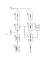
- FIG. 1 is a block diagram showing an example of the overall configuration of radio base station 10 according to the present embodiment.
- a radio base station 10 illustrated in FIG. 1 includes a scheduler 101, a transmission signal generation unit 102, an encoding / modulation unit 103, a mapping unit 104, a transmission unit 105, an antenna 106, a reception unit 107, and a control unit. 108, a channel estimation unit 109, and a demodulation / decoding unit 110 are employed.
- the radio base station 10 has a configuration of MU-MIMO (Multi-User Multiple-Input Multiple-Output) that performs communication simultaneously with a plurality of user terminals 20.
- MU-MIMO Multi-User Multiple-Input Multiple-Output
- the scheduler 101 performs scheduling (for example, resource allocation) of DL signals (DL data signals, DL control signals, DMRS, and the like). In addition, the scheduler 101 performs scheduling (for example, resource allocation) of UL signals (UL data signal, UL control signal, DMRS, and the like).
- the scheduler 101 prepares in advance a plurality of mapping patterns indicating resource elements to which the DMRS of the DL signal is mapped. For example, based on the request conditions and / or the propagation path environment of each user terminal 20, a plurality of mapping patterns are prepared. One mapping pattern is selected from the above. Plural mapping patterns are different from each other in DMRS density (for example, the arrangement interval and / or the number of DMRSs in the frequency direction and / or the time direction). Further, the mapping pattern may specify a resource element that maps DMRS across a plurality of layers.
- the requirements of the user terminal 20 and / or the propagation path environment include, for example, high channel frequency selectivity, high reception quality at the user terminal 20, short reception processing time, and movement of the user terminal 20. Including at least one of the speeds.
- the scheduler 101 selects a different mapping pattern for each user terminal 20. Note that the scheduler 101 may select the same mapping pattern for a plurality of user terminals 20.
- the scheduler 101 sets the mapping pattern of each user terminal 20 based on the selected mapping pattern. For example, when the selected mapping pattern includes DMRSs (plural DMRS ports) of a plurality of layers, the scheduler 101 assigns one or more layers (one or more DMRS ports) to each user terminal 20.
- the DMRS mapping pattern set in the user terminal 20 is referred to as a user pattern. That is, in this case, the user pattern adopts a configuration that specifies resource elements of some layers of the mapping pattern that specifies resource elements that map DMRS across a plurality of layers.
- mapping patterns prepared in advance A specific example of a plurality of mapping patterns prepared in advance and a specific example of a user pattern set based on a plurality of mapping patterns will be described later.
- Each user pattern has an associated index.
- the user terminal 20 specifies the said user pattern by notifying the user terminal 20 of the index which shows the set user pattern.
- the index indicating the user pattern may be notified to the user terminal 20 by, for example, higher layer (for example, RRC (Radio Resource Control) or MAC (Medium Access Control)) signaling, or the user terminal 20 by physical layer (PHY) signaling. May be notified.
- higher layer for example, RRC (Radio Resource Control) or MAC (Medium Access Control)
- PHY physical layer
- the user pattern may be uniquely associated with at least one of other parameters (for example, system bandwidth, carrier frequency, information on DL data signal (for example, mapping pattern of DL data signal, etc.)).
- other parameters for example, system bandwidth, carrier frequency, information on DL data signal (for example, mapping pattern of DL data signal, etc.)
- the user terminal 20 can identify the user pattern implicitly based on other parameters. Therefore, signaling for notifying a user pattern can be reduced.
- the setting of the DMRS user pattern of the DL signal is not limited to being executed by the radio base station 10 (scheduler 101), and may be executed by the user terminal 20.
- the radio base station 10 may receive an index notification indicating the set user pattern from the user terminal 20 (not shown).
- the scheduler 101 sets a user pattern for each user terminal 20 and outputs scheduling information including the user pattern to the transmission signal generation unit 102 and the mapping unit 104.
- the scheduler 101 sets the MCS (coding rate, modulation scheme, etc.) of the DL data signal and the UL data signal based on the channel quality between the radio base station 10 and the user terminal 20, for example, and MCS information Are output to the transmission signal generation unit 102 and the encoding / modulation unit 103.
- MCS is not limited to being set by the radio base station 10 and may be set by the user terminal 20.
- the radio base station 10 may receive MCS information from the user terminal 20 (not shown).
- the transmission signal generation unit 102 generates a transmission signal (including a DL data signal and a DL control signal).
- the DL control signal includes scheduling information output from the scheduler 101 (eg, DL data signal resource allocation information) or downlink control information (DCI: Downlink Control Information) including MCS information.
- DCI Downlink Control Information
- the transmission signal generation unit 102 outputs the generated transmission signal to the encoding / modulation unit 103.
- the encoding / modulation unit 103 performs encoding processing and modulation processing on the transmission signal input from the transmission signal generation unit 102 based on the MCS information input from the scheduler 101, for example. Encoding / modulating section 103 outputs the modulated transmission signal to mapping section 104.
- the mapping unit 104 maps the transmission signal input from the encoding / modulation unit 103 to a predetermined radio resource (DL resource) based on the scheduling information (for example, DL resource allocation) input from the scheduler 101. Further, the mapping unit 104 maps a reference signal (for example, DMRS) to a predetermined radio resource (DL resource) based on the scheduling information. The mapping unit 104 outputs the DL signal mapped to the radio resource to the transmission unit 105.
- DL resource for example, DL resource allocation
- the transmission unit 105 performs transmission processing such as up-conversion and amplification on the DL signal input from the mapping unit 104 and transmits a radio frequency signal (DL signal) from the antenna 106.
- transmission processing such as up-conversion and amplification on the DL signal input from the mapping unit 104 and transmits a radio frequency signal (DL signal) from the antenna 106.
- DL signal radio frequency signal
- the reception unit 107 performs reception processing such as amplification and down-conversion on the radio frequency signal (UL signal) received by the antenna 106 and outputs the UL signal to the control unit 108.
- reception processing such as amplification and down-conversion on the radio frequency signal (UL signal) received by the antenna 106 and outputs the UL signal to the control unit 108.
- the control unit 108 separates (demappings) the UL data signal and the DMRS from the UL signal input from the receiving unit 107 based on the scheduling information (UL resource allocation) input from the scheduler 101. Then, control section 108 outputs the UL data signal to demodulation / decoding section 110 and outputs DMRS to channel estimation section 109.
- the channel estimation unit 109 performs channel estimation using the DMRS of the UL signal, and outputs a channel estimation value that is an estimation result to the demodulation / decoding unit 110.
- the demodulation / decoding unit 110 performs demodulation and decoding processing on the UL data signal input from the control unit 108 based on the channel estimation value input from the channel estimation unit 109.
- the demodulation / decoding unit 110 transfers the demodulated UL data signal to an application unit (not shown).
- the application unit performs processing related to a layer higher than the physical layer or the MAC layer.
- FIG. 2 is a block diagram showing an example of the overall configuration of the user terminal 20 according to the present embodiment.
- 2 includes an antenna 201, a receiving unit 202, a control unit 203, a channel estimation unit 204, a demodulation / decoding unit 205, a transmission signal generation unit 206, an encoding / modulation unit 207, and the like.
- a configuration including a mapping unit 208 and a transmission unit 209 is employed.
- the receiving unit 202 performs reception processing such as amplification and down-conversion on the radio frequency signal (DL signal) received by the antenna 201, and outputs the DL signal to the control unit 203.
- the DL signal includes at least a DL data signal and DMRS.
- the control unit 203 separates (demappings) the DL control signal and the DMRS from the DL signal input from the receiving unit 202. Then, control section 203 outputs the DL control signal to demodulation / decoding section 205 and outputs DMRS to channel estimation section 204.
- control unit 203 controls the reception of the DMRS from the DL signal based on the user pattern notified in advance.
- control unit 203 demultiplexes the DL data signal from the DL signal based on the scheduling information (for example, DL resource allocation information) input from the demodulation / decoding unit 205, and demodulates the DL data signal. Output to the decoding unit 205.
- scheduling information for example, DL resource allocation information
- the channel estimation unit 204 performs channel estimation using the separated DMRS, and outputs a channel estimation value as an estimation result to the demodulation / decoding unit 205.
- the demodulation / decoding unit 205 demodulates the DL control signal input from the control unit 203. Further, the demodulation / decoding unit 205 performs a decoding process (for example, a blind detection process) on the demodulated DL control signal. Demodulation / decoding section 205 sends scheduling information (mapping setting including DL / UL resource allocation or DMRS user pattern) addressed to itself obtained by decoding the DL control signal to control section 203 and mapping section 208. The MCS information for the UL data signal is output to the encoding / modulation unit 207.
- a decoding process for example, a blind detection process
- Demodulation / decoding section 205 sends scheduling information (mapping setting including DL / UL resource allocation or DMRS user pattern) addressed to itself obtained by decoding the DL control signal to control section 203 and mapping section 208.
- the MCS information for the UL data signal is output to the encoding / modulation unit 207.
- the demodulation / decoding unit 205 uses the channel estimation value input from the channel estimation unit 204 based on the MCS information for the DL data signal included in the DL control signal input from the control unit 203, from the control unit 203. Demodulation and decoding are performed on the input DL data signal. Further, the demodulation / decoding unit 205 transfers the demodulated DL data signal to an application unit (not shown). The application unit performs processing related to a layer higher than the physical layer or the MAC layer.
- the transmission signal generation unit 206 generates a transmission signal (including a UL data signal or a UL control signal), and outputs the generated transmission signal to the encoding / modulation unit 207.
- the encoding / modulation unit 207 performs encoding processing and modulation processing on the transmission signal input from the transmission signal generation unit 206 based on, for example, MCS information input from the demodulation / decoding unit 205. Encoding / modulating section 207 outputs the modulated transmission signal to mapping section 208.
- mapping section 208 maps the transmission signal input from encoding / modulation section 207 to a predetermined radio resource (UL resource). . Further, the mapping unit 208 maps a reference signal (for example, DMRS) to a predetermined radio resource (UL resource) based on scheduling information (for example, mapping setting including a DMRS user pattern).
- a reference signal for example, DMRS
- UL resource a predetermined radio resource
- the transmission unit 209 performs transmission processing such as up-conversion and amplification on the UL signal (including at least the UL data signal and DMRS) input from the mapping unit 208, and transmits a radio frequency signal (UL signal) from the antenna 201. Send.
- mapping patterns a specific example of a plurality of mapping patterns and a specific example of a user pattern set based on the plurality of mapping patterns will be described.
- mapping pattern (or user pattern) with a low DMRS density thins out a part of an RE in which DMRS is arranged in a mapping pattern (or user pattern) with a high DMRS density.
- FIG. 3 is a diagram illustrating a user pattern of the first configuration example.
- FIG. 3 shows two user patterns (user pattern # 1 and user pattern # 2) as an example.
- Each user pattern indicates a DMRS mapping position in a resource unit (RU: Resource Unit) (also referred to as a resource block, a resource block pair, etc.) as a resource allocation unit.
- the RU has a configuration in which 168 resource elements (REs) are arranged in the time direction and 12 in the frequency direction.
- One RE is a radio resource area defined by one symbol and one subcarrier. That is, one RU is composed of 14 symbols and 12 subcarriers.
- the 14 symbols in the time direction of the RU are called SB1 to SB14 in order from the left.
- the 12 subcarriers in the frequency direction of the RU are called SC1 to SC12 in order from the bottom.
- a control signal channel (for example, PDCCH) is arranged in the RE of the first two symbols (that is, SB1 and SB2) of the RU.
- User pattern # 1 (user pattern of user terminal # 1) is a pattern in which DMRS of layer # 1 is arranged relatively densely in SB3, and user pattern # 2 (user pattern of user terminal # 2) is a layer
- the DMRS # 2 is a pattern arranged relatively sparser than the user pattern # 1 in SB3.
- the user pattern # 2 adopts a configuration in which a part of the RE (in FIG. 3, SC5 and SC7 of SB3) is thinned out in the user pattern # 1.
- the DMRS between different user patterns is one of code division multiplexing (CDM: Code Division Multiplexing), time division multiplexing (TDM: Time Division Division Multiplexing), and frequency division multiplexing (FDM). At least one is set to be orthogonal.
- mapping patterns to which the first configuration example is applied and user patterns set based on the mapping patterns will be described as application examples.
- FIG. 4 is a diagram illustrating a mapping pattern of the first application example.
- Each mapping pattern indicates a DMRS mapping position in an RU that is a resource allocation unit.
- the two mapping patterns include DMRS mapping positions of four layers (Layer # 1 to Layer # 4).
- a control signal channel (for example, PDCCH) is arranged in the RE of the first two symbols (that is, SB1 and SB2) of the RU.
- Mapping pattern # 1 is a pattern in which DMRS of each layer is arranged relatively densely in SB3, and mapping pattern # 2 is arranged in which parsed DMRS of each layer is relatively sparser than mapping pattern # 2 in SB3. Pattern.
- mapping pattern # 2 adopts a configuration in which a part of RE in which DMRS in mapping pattern # 1 is arranged is thinned out.
- mapping pattern # 2 employs a configuration in which the REs of SC3, SC4, SC7, SC8, SC11, and SC12 of SB3 in mapping pattern # 1 are thinned out.
- the scheduler 101 of the radio base station 10 selects one mapping pattern for each user terminal from the two mapping patterns shown in FIG. 4 based on the request conditions and / or the propagation path environment of each user terminal. For example, when the user terminal # 1 moves faster than a predetermined speed and the user terminal # 2 moves slower than a predetermined speed, the scheduler 101 sets the mapping pattern # 1 to the user terminal # 1. Select the mapping pattern # 2 for the user terminal # 2. When the user terminal # 1 is lower than the predetermined communication quality and the user terminal # 2 is higher than the predetermined communication quality, the scheduler 101 selects the mapping pattern # 1 for the user terminal # 1, and the user Mapping pattern # 2 is selected for terminal # 2.
- the scheduler 101 sets the user pattern of each user terminal by assigning one or more layers to each user terminal.
- FIG. 5 is a diagram showing a user pattern of the first application example.
- User pattern # 1 (user pattern of user terminal # 1) is composed of layers # 1 and # 3 of mapping pattern # 1
- user pattern # 2 (user pattern of user terminal # 2) is mapping pattern # 2.
- DMRSs are arranged in the same RE in layer # 1 of user pattern # 1 and layer # 2 of user pattern # 2.
- the DMRSs of different user patterns arranged in the same RE lose their orthogonality. Therefore, DMRSs arranged in the same RE of user pattern # 1 and user pattern # 2 are set to be orthogonal by Cyclic Shift (cyclic shift).
- FIG. 6 is a diagram illustrating a first example of Cyclic Shift of the first application example.
- FIG. 6 shows an example of Cyclic Shift of DMRS of layer # 1 and layer # 2 of mapping pattern # 1 and layer # 1 and layer # 2 of mapping pattern # 2 shown in FIG.
- FIG. 6 shows only SB3 in which DMRS is arranged, and other symbols are omitted.
- a to f of each RE indicate a DMRS signal series, and ⁇ 1 and ⁇ 2 indicate different phase rotation amounts. Note that the same value may be applied to a to f, or different values may be applied.
- DM DMRSs of different layers arranged in the same RE in the same mapping pattern are orthogonal by Cyclic Shift.
- the DMRS of the layer # 1 of the mapping pattern # 1 and the DMRS of the layer # 2 of the mapping pattern # 1 in FIG. 6 are orthogonal by a Cyclic Shift that applies different phase rotation amounts.
- the DMRS of layer # 1 of mapping pattern # 2 in FIG. 6 and the DMRS of layer # 2 of mapping pattern # 2 are orthogonal to each other by Cyclic Shift using different phase rotation amounts.
- the same signal series and the same phase rotation amount are applied to DMRSs of the same layer arranged in the same RE in different mapping patterns.
- DMRSs having the same value are arranged in the same RE in different mapping patterns.
- the DMRS of the same RE (SC1, SC5, and SC9) among the DMRS of layer # 1 of mapping pattern # 1 and the DMRS of layer # 2 of mapping pattern # 2 in FIG. 6 applied different phase rotation amounts.
- DMRSs of the same RE are orthogonal in layer # 1 of mapping pattern # 1 assigned as user pattern # 1 and layer # 2 of mapping pattern # 2 assigned as user pattern # 2. It is possible to suppress degradation in channel estimation accuracy in user terminals (user terminal # 1 and user terminal # 2).
- the same signal sequence and the same phase rotation amount are applied to DMRSs of the same layer arranged in the same RE in different mapping patterns.
- DMRSs of different layers arranged in the same RE in different mapping patterns can be made orthogonal to each other. Can do.
- DMRSs are arranged in the same RE in layer # 3 of mapping pattern # 1 assigned as user pattern # 1 and in layer # 4 of mapping pattern # 2 assigned as user pattern # 2. Yes.
- the same layer arranged in the same RE in different mapping patterns as in the relationship between layer # 1 and layer # 2 shown in FIG. By applying the same signal sequence and the same phase rotation amount to different DMRSs, DMRSs of different layers arranged in the same RE in different mapping patterns are orthogonal.
- the signal series and the amount of phase rotation applied to the DMRS arranged in the same RE of user pattern # 1 and user pattern # 2 in FIG. 5 are not limited to the example shown in FIG.
- a second example of a signal sequence and a phase rotation amount applied to DMRS arranged in the same RE of user pattern # 1 and user pattern # 2 in FIG. 5 will be described.
- FIG. 7 is a diagram illustrating a second example of Cyclic Shift of the first application example.
- SB3 in which DMRS is arranged is shown, and other symbols are omitted.
- a to c and x to z of each RE indicate a DMRS signal sequence
- ⁇ 1 , ⁇ 2 , ⁇ 1, and ⁇ 2 indicate different amounts of phase rotation.
- the difference between FIG. 7 and FIG. 6 is that the signal sequence and the amount of phase rotation applied to each DMRS are different.
- the same values may be applied to a to c or / and x to z, or different values may be applied.
- the same value may be applied to a and x, b and y, and c and z, or different values may be applied.
- the same value may be applied to ⁇ 1 and ⁇ 1 and ⁇ 2 and ⁇ 2 , or different values may be applied.
- the same signal series and the same phase rotation amount are applied to DMRSs of the same layer arranged in the same RE in different mapping patterns.
- DMRSs having the same value are arranged in the same RE in different mapping patterns.
- the DMRS of the same RE (SC1, SC5, and SC9) among the DMRS of layer # 1 of mapping pattern # 1 and the DMRS of layer # 2 of mapping pattern # 2 in FIG. 7 applied different phase rotation amounts.
- DMRSs of the same RE are orthogonal in layer # 1 of mapping pattern # 1 assigned as user pattern # 1 and layer # 2 of mapping pattern # 2 assigned as user pattern # 2. It is possible to suppress degradation in channel estimation accuracy in user terminals (user terminal # 1 and user terminal # 2).
- the same signal sequence and the same phase rotation amount are applied to DMRSs of the same layer arranged in the same RE in different mapping patterns.
- DMRSs of different layers arranged in the same RE in different mapping patterns can be made orthogonal to each other. Can do.
- DMRS is arranged in the same RE in layer # 3 of mapping pattern # 1 assigned as user pattern # 1 and layer # 4 of mapping pattern # 2 assigned as user pattern # 2. ing.
- the same layer arranged in the same RE in different mapping patterns as in the relationship between layer # 1 and layer # 2 shown in FIG. By applying the same signal sequence and the same phase rotation amount to different DMRSs, DMRSs of different layers arranged in the same RE in different mapping patterns are orthogonal.
- DMRS may collide with another signal (for example, another user's data channel), but in this case, a user terminal makes other signal noise. Signal processing can be performed.
- FIG. 8 is a diagram illustrating a mapping pattern of the second application example.
- FIG. 8 shows mapping pattern # 1 similar to FIG. 4 and mapping pattern # 3 different from mapping pattern # 2 of FIG.
- Mapping pattern # 3 adopts a configuration in which a part of RE in which DMRS of mapping pattern # 1 is arranged is thinned out.
- the mapping pattern # 3 adopts a configuration in which the SC3 to SC6 of SB3 and the REs of SC9 to SC12 in the mapping pattern # 1 are thinned out.
- the scheduler 101 of the radio base station 10 selects one mapping pattern for each user terminal from the two mapping patterns shown in FIG. 8 based on the request conditions and / or the propagation path environment of each user terminal. For example, when the user terminal # 1 moves faster than a predetermined speed and the user terminal # 2 moves slower than a predetermined speed, the scheduler 101 sets the mapping pattern # 1 to the user terminal # 1. Select the mapping pattern # 3 for the user terminal # 2. When the user terminal # 1 is lower than the predetermined communication quality and the user terminal # 2 is higher than the predetermined communication quality, the scheduler 101 selects the mapping pattern # 1 for the user terminal # 1, and the user Mapping pattern # 3 is selected for terminal # 2.
- the scheduler 101 sets the user pattern of each user terminal by assigning one or more layers to each user terminal.
- mapping pattern # 1 is assigned to user terminal # 1
- layer # 2 and layer # 4 of mapping pattern # 3 are assigned to user terminal # 2. To do.
- FIG. 9 is a diagram showing a user pattern of the second application example.
- User pattern # 1 (user pattern of user terminal # 1) is composed of layers # 1 and # 3 of mapping pattern # 1
- user pattern # 2 (user pattern of user terminal # 2) is mapping pattern # 3.
- the DMRS is arranged in the same RE in the layer # 1 of the user pattern # 1 and the layer # 2 of the user pattern # 2.
- the DMRSs of different user patterns arranged in the same RE lose their orthogonality. Therefore, DMRSs arranged in the same RE of user pattern # 1 and user pattern # 2 are set to be orthogonal by Cyclic Shift.
- FIG. 10 is a diagram illustrating an example of Cyclic Shift of the second application example.
- FIG. 10 illustrates an example of the Cyclic Shift of the DMRSs of the layer # 1 and the layer # 2 of the mapping pattern # 1 and the layers # 1 and # 2 of the mapping pattern # 2 illustrated in FIG.
- SB3 in which DMRS is arranged is shown, and other symbols are omitted.
- a to f of each RE indicate a DMRS signal sequence
- ⁇ 1 and ⁇ 2 indicate mutually different phase rotation amounts. Note that the same value may be applied to a to f, or different values may be applied.
- DMRSs of different layers arranged in the same RE in the same mapping pattern are orthogonal by Cyclic Shift.
- the same signal series and the same phase rotation amount are applied to DMRSs of the same layer arranged in the same RE in different mapping patterns.
- DMRSs having the same value are arranged in the same RE in different mapping patterns.
- the DMRS arranged in the SC7 of the layer # 1 of the mapping pattern # 1 and the DMRS arranged in the SC7 of the layer # 1 of the mapping pattern # 3 in FIG. ⁇ 1 ⁇ 3/6 is applied.
- the DMRS of the same RE (SC1 and SC7) among the DMRS of layer # 1 of mapping pattern # 1 and the DMRS of layer # 2 of mapping pattern # 3 in FIG. Is orthogonal.
- DMRSs of the same RE are orthogonal in layer # 1 of mapping pattern # 1 assigned as user pattern # 1 and layer # 2 of mapping pattern # 3 assigned as user pattern # 2. It is possible to suppress degradation in channel estimation accuracy in user terminals (user terminal # 1 and user terminal # 2).
- the same signal sequence and the same phase rotation amount are applied to DMRSs of the same layer arranged in the same RE in different mapping patterns.
- DMRSs of different layers arranged in the same RE in different mapping patterns can be made orthogonal to each other. Can do.
- DMRSs are arranged in the same RE in layer # 3 of mapping pattern # 1 assigned as user pattern # 1 and layer # 4 of mapping pattern # 3 assigned as user pattern # 2. Yes.
- the DMRS arranged in the same RE of layer # 3 and layer # 4 the same layer arranged in the same RE in different mapping patterns as in the relationship between layers # 1 and # 2 shown in FIG.
- DMRSs of different layers arranged in the same RE in different mapping patterns are orthogonal.
- DMRS may collide with another signal (for example, another user's data channel), and in this case, the user terminal makes other signal noise. Signal processing can be performed.
- FIG. 11 is a diagram illustrating a mapping pattern of the third application example.
- FIG. 11 shows mapping pattern # 1 similar to FIGS. 4 and 8, and mapping pattern # 4 different from mapping pattern # 2 in FIG. 4 and mapping pattern # 3 in FIG.
- Mapping pattern # 4 adopts a configuration in which a part of RE in which DMRS of mapping pattern # 1 is arranged is thinned out. In the example of FIG. 11, mapping pattern # 4 adopts a configuration in which the REs of SC7 to SC12 of SB3 in mapping pattern # 1 are thinned out.
- the scheduler 101 of the radio base station 10 selects one mapping pattern for each user terminal from the two mapping patterns shown in FIG. 11 based on the request conditions and / or the propagation path environment of each user terminal. For example, when the user terminal # 1 moves faster than a predetermined speed and the user terminal # 2 moves slower than a predetermined speed, the scheduler 101 sets the mapping pattern # 1 to the user terminal # 1. Select the mapping pattern # 4 for the user terminal # 2. When the user terminal # 1 is lower than the predetermined communication quality and the user terminal # 2 is higher than the predetermined communication quality, the scheduler 101 selects the mapping pattern # 1 for the user terminal # 1, and the user Mapping pattern # 4 is selected for terminal # 2.
- the scheduler 101 sets the user pattern of each user terminal by assigning one or more layers to each user terminal.
- FIG. 12 is a diagram showing a user pattern of the third application example.
- User pattern # 1 (user pattern of user terminal # 1) is composed of layers # 1 and # 3 of mapping pattern # 1
- user pattern # 2 (user pattern of user terminal # 2) is mapping pattern # 4.
- the DMRS is arranged in the same RE in the layer # 1 of the user pattern # 1 and the layer # 2 of the user pattern # 2.
- the DMRSs of different user patterns arranged in the same RE lose their orthogonality. Therefore, DMRSs arranged in the same RE of user pattern # 1 and user pattern # 2 are set to be orthogonal by Cyclic Shift.
- FIG. 13 is a diagram illustrating an example of Cyclic Shift of the third application example.
- FIG. 13 illustrates an example of the Cyclic Shift of the DMRSs of the layer # 1 and the layer # 2 of the mapping pattern # 1 and the layers # 1 and # 2 of the mapping pattern # 2 illustrated in FIG.
- FIG. 13 shows only SB3 in which DMRS is arranged, and other symbols are omitted.
- a to c of each RE indicate a DMRS signal series
- ⁇ 1 and ⁇ 2 indicate different phase rotation amounts. Note that the same value may be applied to a to c, or different values may be applied.
- DMRSs of different layers arranged in the same RE in the same mapping pattern are orthogonal by Cyclic Shift.
- the same signal series and the same phase rotation amount are applied to DMRSs of the same layer arranged in the same RE in different mapping patterns.
- DMRSs having the same value are arranged in the same RE in different mapping patterns.
- the DMRS of the same RE (SC1, SC3, and SC5) among the DMRS of layer # 1 of mapping pattern # 1 and the DMRS of layer # 2 of mapping pattern # 4 in FIG. 13 applied different phase rotation amounts.
- DMRSs of the same RE are orthogonal in layer # 1 of mapping pattern # 1 assigned as user pattern # 1 and layer # 2 of mapping pattern # 4 assigned as user pattern # 2. It is possible to suppress degradation in channel estimation accuracy in user terminals (user terminal # 1 and user terminal # 2).
- the same signal sequence and the same phase rotation amount are applied to DMRSs of the same layer arranged in the same RE in different mapping patterns.
- DMRSs of different layers arranged in the same RE in different mapping patterns can be made orthogonal to each other. Can do.
- DMRSs are arranged in the same RE in layer # 3 of mapping pattern # 1 assigned as user pattern # 1 and in layer # 4 of mapping pattern # 4 assigned as user pattern # 2. Yes.
- the DMRS arranged in the same RE of layer # 3 and layer # 4 the same layer arranged in the same RE in different mapping patterns as in the relationship between layer # 1 and layer # 2 shown in FIG.
- DMRSs of different layers arranged in the same RE in different mapping patterns are orthogonal.
- DMRS may collide with another signal (for example, another user's data channel).
- another signal for example, another user's data channel.
- the user terminal makes other signal noise. Signal processing can be performed.
- the orthogonal method is changed by changing the layer assigned to each user terminal.
- FIG. 14 is a diagram illustrating a user pattern of the fourth application example.
- FIG. 14 shows that the scheduler 101 assigns layer # 1 and layer # 2 of mapping pattern # 1 (see FIG. 4) to user terminal # 1, and mapping pattern # 2 (see FIG. 4) to user terminal # 2. ) Shows an example in which layer # 3 and layer # 4 are assigned.
- the user pattern # 1 (user terminal # 1 user pattern) in FIG. 14 includes the mapping pattern # 1 layer # 1 and layer # 2 shown in FIG. 4, and the user pattern # 2 (user terminal # 2).
- the user pattern) includes the layer # 3 and the layer # 4 of the mapping pattern # 2 shown in FIG.
- DMRSs are arranged on different subcarriers of the same symbol (SB3).
- SB3 subcarriers of the same symbol
- DMRSs between different user patterns are not arranged in the same RE, but are arranged in different frequencies (subcarriers), so that channel estimation in each user terminal (user terminal # 1 and user terminal # 2) Degradation of accuracy can be suppressed.
- DMRS may collide with another signal (for example, another user's data channel), but in this case, a user terminal makes other signal noise. Signal processing can be performed.
- FIG. 15 is a diagram illustrating a mapping pattern of the fifth application example.
- FIG. 15 shows mapping pattern # 5 and mapping pattern # 6.
- mapping pattern # 5 and mapping pattern # 6 include DMRS mapping positions of four layers (Layer # 1 to Layer # 4).
- a control signal channel (for example, PDCCH) is arranged in the RE of the first two symbols (that is, SB1 and SB2) of the RU.
- Mapping pattern # 5 is a pattern in which DMRS of each layer is relatively densely arranged in SB3
- mapping pattern # 6 is a pattern in which DMRS of each layer is relatively sparsely arranged in SB3 than mapping pattern # 5 It is a pattern.
- the mapping pattern # 6 adopts a configuration in which a part of the RE in which the DMRS in the mapping pattern # 5 is arranged is thinned out.
- the mapping pattern # 6 adopts a configuration in which the REs of SC5 to SC8 of SB3 in mapping pattern # 5 are thinned out.
- the scheduler 101 of the radio base station 10 selects one mapping pattern for each user terminal from the two mapping patterns shown in FIG. 15 based on the request conditions and / or the propagation path environment of each user terminal. For example, when the user terminal # 1 moves faster than the predetermined speed and the user terminal # 2 moves slower than the predetermined speed, the scheduler 101 sets the mapping pattern # 5 to the user terminal # 1. Select the mapping pattern # 6 for the user terminal # 2. When the user terminal # 1 is lower than the predetermined communication quality and the user terminal # 2 is higher than the predetermined communication quality, the scheduler 101 selects the mapping pattern # 5 for the user terminal # 1, and the user Mapping pattern # 6 is selected for terminal # 2.
- the scheduler 101 sets the user pattern of each user terminal by assigning one or more layers to each user terminal.
- mapping pattern # 5 are assigned to user terminal # 1
- layer # 2 and layer # 4 of mapping pattern # 6 are assigned to user terminal # 2. To do.
- FIG. 16 is a diagram showing a user pattern of the fifth application example.
- User pattern # 1 (user pattern of user terminal # 1) is composed of layers # 1 and # 3 of mapping pattern # 5, and user pattern # 2 (user pattern of user terminal # 2) is mapping pattern # 6. Layer # 2 and layer # 4.
- the DMRS is arranged in the same RE in the layer # 1 of the user pattern # 1 and the layer # 2 of the user pattern # 2.
- the DMRSs of different user patterns arranged in the same RE lose their orthogonality. Therefore, DMRSs arranged in the same RE of user pattern # 1 and user pattern # 2 are set to be orthogonal using an OCC sequence.
- FIG. 17 is a diagram illustrating an example of the OCC sequence of the fifth application example.
- FIG. 17 shows an example of the OCRS sequence of DMRSs of layer # 1 and layer # 2 of mapping pattern # 5 and layers # 1 and # 2 of mapping pattern # 6 shown in FIG.
- FIG. 17 shows only SB3 in which DMRS is arranged, and other symbols are omitted.
- a to c of each RE indicate DMRS signal sequences
- (+1) and ( ⁇ 1) indicate elements of an OCC sequence having a sequence length of 2, respectively. Note that the same value may be applied to a to c, or different values may be applied. Different values may be applied to a to c between different layers.
- the DMRSs of different layers arranged in the same RE in the same mapping pattern are orthogonal using the OCC sequence.
- the DMRS of layer # 1 of mapping pattern # 5 in FIG. 17 and the DMRS of layer # 2 of mapping pattern # 5 are orthogonal using an OCC sequence.
- an OCC sequence composed of (+1) and (+1) is applied to the DMRS arranged in SC1 and SC2 of layer # 1 of mapping pattern # 5, and layer # 2 of mapping pattern # 5
- the OCC sequence consisting of (+1) and ( ⁇ 1) is applied to the DMRS arranged in SC1 and SC2.
- the DMRS of layer # 1 of mapping pattern # 6 in FIG. 17 and the DMRS of layer # 2 of mapping pattern # 6 are orthogonal using an OCC sequence.
- the same signal sequence and the same OCC sequence are applied to DMRSs of the same layer arranged in the same RE in different mapping patterns.
- DMRSs having the same value are arranged in the same RE in different mapping patterns.
- the signal sequence a is applied to the DMRS arranged in SC1 and SC2 of layer # 1 of mapping pattern # 5 and the DMRS arranged in SC1 and SC2 of layer # 1 of mapping pattern # 6 in FIG. Then, an OCC sequence composed of (+1) and (+1) is applied to each signal sequence.
- the DMRS of the same RE (SC1 and SC2 and SC9 and SC10) among the DMRS of layer # 1 of mapping pattern # 5 and the DMRS of layer # 2 of mapping pattern # 6 in FIG. 17 uses an OCC sequence. Orthogonal.
- the DMRSs of the same RE are orthogonal in layer # 1 of mapping pattern # 5 assigned as user pattern # 1 and layer # 2 of mapping pattern # 6 assigned as user pattern # 2. It is possible to suppress degradation in channel estimation accuracy in user terminals (user terminal # 1 and user terminal # 2).
- the same signal sequence and the same OCC sequence are applied to DMRSs of the same layer arranged in the same RE in different mapping patterns.
- the orthogonality of DMRS between different layers of one mapping pattern can be used between mapping patterns, DMRSs of different layers arranged in the same RE in different mapping patterns can be made orthogonal to each other. Can do.
- DMRSs are arranged in the same RE in layer # 3 of mapping pattern # 5 assigned as user pattern # 1 and layer # 4 of mapping pattern # 6 assigned as user pattern # 2. Yes.
- the same layer arranged in the same RE in different mapping patterns as in the relationship between layer # 1 and layer # 2 shown in FIG. By applying the same signal sequence and the same OCC sequence to different DMRSs, DMRSs of different layers arranged in the same RE in different mapping patterns are orthogonal.
- DMRS may collide with another signal (for example, another user's data channel).
- another signal for example, another user's data channel.
- the user terminal makes other signal noise. Signal processing can be performed.
- the DMRS may be orthogonalized using another orthogonal sequence different from the OCC sequence.
- DMRSs of different layers with different mapping patterns are orthogonalized using an OCC sequence.
- DMRSs of different layers in the same user pattern are orthogonalized by FDM.
- the orthogonal method may be changed by changing the layer assigned to each user terminal.
- the orthogonal method may be changed by changing the layer assigned to each user terminal.
- FIG. 18 is a diagram illustrating a user pattern of the sixth application example.
- the scheduler 101 assigns layer # 1 and layer # 2 of mapping pattern # 5 (see FIG. 15) to user terminal # 1, and mapping pattern # 6 (see FIG. 15) to user terminal # 2.
- user pattern # 1 in FIG. 18 is composed of layer # 1 and layer # 2 of mapping pattern # 5 shown in FIG. 15, and user pattern # 2 (user terminal # 2).
- the user pattern) is composed of the layer # 3 and the layer # 4 of the mapping pattern # 6 shown in FIG.
- DMRSs are arranged on different frequencies (subcarriers) of the same symbol (SB3).
- SB3 subcarriers of the same symbol
- DMRS between different user patterns is orthogonalized by FDM.
- DMRSs of different layers within the same user pattern are orthogonal using an OCC sequence.
- the same signal sequence and the same OCC sequence are applied to DMRSs of the same layer arranged in the same RE in different mapping patterns.
- an OCC sequence is applied like layer # 1 and layer # 2 of mapping pattern # 5 shown in FIG.
- the DMRSs of different layers are orthogonalized using the OCC sequence.
- DMRSs between different user patterns are not arranged in the same RE, but are arranged in different frequencies (subcarriers), so that channel estimation in each user terminal (user terminal # 1 and user terminal # 2) Degradation of accuracy can be suppressed.
- DMRS may collide with another signal (for example, another user's data channel), but in this case, a user terminal makes other signal noise. Signal processing can be performed.
- a mapping pattern with a low DMRS density is one of two mapping patterns having different DMRS densities (for example, arrangement intervals and / or numbers of DMRSs in the frequency direction and / or time direction).
- DMRS densities for example, arrangement intervals and / or numbers of DMRSs in the frequency direction and / or time direction.
- the DMRS when viewed from a user pattern set based on a mapping pattern having a low DMRS density (user pattern # 2 described above), the DMRS is set based on a mapping pattern having a high DMRS density.
- DMRSs arranged in the same RE as the user pattern (user pattern # 1 described above) are orthogonal using an OCC sequence or Cyclic Shift.
- the DMRS arranged in the same RE as user pattern # 2 is orthogonal using an OCC sequence or Cyclic Shift.
- the DMRS arranged in the RE different from the user pattern # 2 collides with another signal (for example, another user's data channel).
- the user terminal can perform signal processing by regarding the other signal as noise.
- the first configuration example an example in which different layers (different DMRS ports) with different mapping patterns are assigned between user terminals has been described. For example, when the same layer (same DMRS port) of a different mapping pattern is allocated between user terminals, the method of the first configuration example described above may not be applied.
- the scheduler 101 selects one mapping pattern for each user terminal from mapping patterns prepared in advance, and a plurality of layers (a plurality of DMRS ports) of the selected mapping pattern
- a plurality of user patterns may be prepared in advance, and the scheduler 101 may select different user patterns between the user terminals based on the user terminal request conditions and / or the propagation path environment.
- DMRSs mapped to REs defined for each of a plurality of user patterns are set to be orthogonal to each other between different user patterns.
- the present invention is not limited to this.
- the number of REs that map the DMRS may be the same.
- the present invention is not limited to the first configuration example, and various configurations can be adopted.
- a second configuration example an example will be described in which a DMRS with a low-density mapping pattern is arranged in an RE different from a DMRS with a high-density mapping pattern.
- FIG. 19 is a diagram illustrating a user pattern of the second configuration example.
- three user patterns (user pattern # 1, user pattern # 2, and user pattern # 3) are shown as an example.
- Each user pattern indicates a DMRS mapping position in an RU that is a resource allocation unit.
- a control signal channel (for example, PDCCH) is arranged in the RE of the first two symbols (that is, SB1 and SB2) of the RU.
- User pattern # 1 (user pattern of user terminal # 1) is a pattern in which DMRS of layer # 1 is arranged relatively densely in SB3, and user pattern # 2 (user pattern of user terminal # 2) is a layer The DMRS # 2 is a pattern arranged relatively sparser than the user pattern # in SB3.
- User pattern # 3 (user pattern of user terminal # 3) is a pattern in which DMRS of layer # 3 is arranged relatively sparser than user pattern # 1 in SB4.
- user pattern # 2 arranges DMRS in the same symbol as the symbol (SB3) in which DMRS of user pattern # 1 is arranged, but has a frequency (sub frequency different from the subcarrier in which DMRS of user pattern # 1 is arranged.
- a configuration in which DMRS is arranged in the carrier) is adopted.
- DMRS of user pattern # 1 A configuration is adopted in which DMRS is arranged in a symbol (for example, SB4) different from the symbol in which is arranged.
- the DMRS of user pattern # 1 and the DMRS of user pattern # 2 are orthogonal by FDM.
- the DMRS of user pattern # 1 and the DMRS of user pattern # 3 are orthogonal by TDM.
- the DMRS of user pattern # 2 and the DMRS of user pattern # 3 are orthogonal by FDM and TDM. Therefore, it is possible to suppress deterioration in channel estimation accuracy in each user terminal (user terminal # 1 and user terminal # 2).
- DMRS may collide with another signal (for example, another user's data channel), but in this case, a user terminal makes other signal noise. Signal processing can be performed.
- the number of REs that map DMRSs is different from each other in each user pattern, but the present invention is not limited to this.
- the number of REs that map the DMRS may be the same.
- the user patterns are orthogonal to each other between the user patterns by FDM and / or TDM.
- a DMRS with a low-density mapping pattern is placed in the same RE as a DMRS arranged in a different RE from a DMRS with a high-density mapping pattern, and a part of the DMRS with a high-density mapping pattern.
- An example including a DMRS to be arranged will be described.
- FIG. 20 is a diagram illustrating a user pattern of the third configuration example.
- FIG. 20 shows two user patterns (user pattern # 1 and user pattern # 2) as an example.
- Each user pattern indicates a DMRS mapping position in an RU that is a resource allocation unit.
- a control signal channel (for example, PDCCH) is arranged in the RE of the first two symbols (that is, SB1 and SB2) of the RU.
- User pattern # 1 (user pattern of user terminal # 1) is a pattern in which DMRS of layer # 1 is arranged relatively densely in SB3, and user pattern # 2 (user pattern of user terminal # 2) is a layer
- the DMRS # 2 is a pattern arranged relatively sparser than the user pattern # in SB3.
- the DMRS of user pattern # 2 includes the DMRS arranged on the same frequency (subcarrier) (SC1 and SC7) as the subcarrier on which the DMRS of user pattern # 1 is arranged, and the DMRS of user pattern # 1.
- a configuration including DMRS arranged in subcarriers (SC4 and SC10) different from the subcarrier to be used is adopted.
- the DMRSs arranged in SC1 and SC7 of SB3 included in user pattern # 2 and user pattern # 1 are DMRSs arranged in the same RE, the method shown in the first configuration example For example, they are orthogonalized by a method using Cyclic Shift or a method using an OCC sequence.
- DMRSs arranged in SC3, SC5, SC9 and SC11 of SB3 in user pattern # 1 and DMRSs arranged in SC4 and SC10 of SB3 in user pattern # 2 are DMRSs arranged in different REs. For this reason, orthogonalization is performed by the method shown in the second configuration example, for example, FDM and / or TDM. In the example of FIG. 20, they are orthogonalized by FDM.
- the present invention is not limited to this.
- the number of REs that map the DMRS may be the same. In that case, in each user pattern, in each user pattern, some of the REs that map DMRS are different from each other, and the rest are the same. In this case, DMRSs in which part of REs to be mapped are different from each other are orthogonal to each other between user patterns by FDM and / or TDM.
- the method shown in the first configuration example (Cyclic The method is orthogonal using a method using Shift or a method using an orthogonal sequence.
- a user pattern (DMRS mapping pattern of a user terminal) is set based on one mapping pattern selected from a plurality of mapping patterns prepared in advance.
- DMRSs of a plurality of mapping patterns are set to be orthogonal to each other by at least one of FDM, CDM, and / or CDM.
- a control signal channel for example, PDCCH
- PDCCH Physical Downlink Control Channel
- the number of layers (number of DMRS ports) in the present embodiment is merely an example, and the present invention is not limited to this.
- the number of DMRS layers may be 5 or more, or 3 or less.
- the number of mapping patterns is two and the number of user terminals (the number of user patterns) is mainly described, but the present invention is not limited to this.
- the number of mapping patterns and / or the number of user terminals may be three or more.
- DMRS is mainly arranged in the third symbol (SB3) of RU
- SB3 third symbol
- the DMRS may be arranged after the fourth symbol or before the second symbol.
- Additional DMRS may be arranged.
- Additional DMRS is, for example, a DMRS arranged to improve followability to channel time fluctuations when the user terminal 20 is moving at high speed.
- the DMRS to which the present invention is applied is not particularly limited.
- the present invention may be applied only to the above-described Front-loaded DMRS, may be applied only to Additional-DMRS, or may be applied to both.
- the RU to which the present invention is applied is not particularly limited.
- the present invention may be applied to RUs at all carrier frequencies, or the present invention may be applied to RUs at some carrier frequencies.
- each functional block may be realized by one device physically and / or logically coupled, and two or more devices physically and / or logically separated may be directly and / or indirectly. (For example, wired and / or wireless) and may be realized by these plural devices.
- a wireless base station, a user terminal, etc. in an embodiment of the present invention may function as a computer that performs processing of the wireless communication method of the present invention.
- FIG. 21 is a diagram illustrating an example of a hardware configuration of a radio base station and a user terminal according to an embodiment of the present invention.
- the wireless base station 10 and the user terminal 20 described above may be physically configured as a computer device including a processor 1001, a memory 1002, a storage 1003, a communication device 1004, an input device 1005, an output device 1006, a bus 1007, and the like. Good.
- the term “apparatus” can be read as a circuit, a device, a unit, or the like.
- the hardware configurations of the radio base station 10 and the user terminal 20 may be configured to include one or a plurality of each device illustrated in the figure, or may be configured not to include some devices.
- processor 1001 may be implemented by one or more chips.
- Each function in the radio base station 10 and the user terminal 20 is obtained by reading predetermined software (program) on hardware such as the processor 1001 and the memory 1002, so that the processor 1001 performs computation and communication by the communication device 1004, or This is realized by controlling data reading and / or writing in the memory 1002 and the storage 1003.
- predetermined software program
- the processor 1001 performs computation and communication by the communication device 1004, or This is realized by controlling data reading and / or writing in the memory 1002 and the storage 1003.
- the processor 1001 controls the entire computer by operating an operating system, for example.
- the processor 1001 may be configured by a central processing unit (CPU) including an interface with peripheral devices, a control device, an arithmetic device, a register, and the like.
- CPU central processing unit
- the above-described scheduler 101, control units 108 and 203, transmission signal generation units 102 and 206, encoding / modulation units 103 and 207, mapping units 104 and 208, channel estimation units 109 and 204, demodulation / decoding units 110 and 205 Etc. may be realized by the processor 1001.
- the processor 1001 reads a program (program code), software module, or data from the storage 1003 and / or the communication device 1004 to the memory 1002, and executes various processes according to these.
- a program program code
- the scheduler 101 of the radio base station 10 may be realized by a control program stored in the memory 1002 and operated by the processor 1001, and may be realized similarly for other functional blocks.
- the above-described various processes have been described as being executed by one processor 1001, they may be executed simultaneously or sequentially by two or more processors 1001.
- the processor 1001 may be implemented by one or more chips. Note that the program may be transmitted from a network via a telecommunication line.
- the memory 1002 is a computer-readable recording medium and includes at least one of ROM (Read Only Memory), EPROM (Erasable Programmable ROM), EEPROM (Electrically Erasable Programmable ROM), RAM (Random Access Memory), and the like. May be.
- the memory 1002 may be called a register, a cache, a main memory (main storage device), or the like.
- the memory 1002 can store a program (program code), a software module, and the like that can be executed to implement the wireless communication method according to the embodiment of the present invention.
- the storage 1003 is a computer-readable recording medium such as an optical disc such as a CD-ROM (Compact Disc ROM), a hard disc drive, a flexible disc, a magneto-optical disc (eg, a compact disc, a digital versatile disc, a Blu-ray). (Registered trademark) disk, smart card, flash memory (for example, card, stick, key drive), floppy (registered trademark) disk, magnetic strip, and the like.
- the storage 1003 may be referred to as an auxiliary storage device.
- the storage medium described above may be, for example, a database, server, or other suitable medium including the memory 1002 and / or the storage 1003.
- the communication device 1004 is hardware (transmission / reception device) for performing communication between computers via a wired and / or wireless network, and is also referred to as a network device, a network controller, a network card, a communication module, or the like.
- a network device for example, the transmission units 105 and 209, the antennas 106 and 201, the reception units 107 and 202, and the like described above may be realized by the communication device 1004.
- the input device 1005 is an input device (for example, a keyboard, a mouse, a microphone, a switch, a button, a sensor, etc.) that accepts an input from the outside.
- the output device 1006 is an output device (for example, a display, a speaker, an LED lamp, etc.) that performs output to the outside.
- the input device 1005 and the output device 1006 may have an integrated configuration (for example, a touch panel).
- each device such as the processor 1001 and the memory 1002 is connected by a bus 1007 for communicating information.
- the bus 1007 may be configured with a single bus or may be configured with different buses between apparatuses.
- the radio base station 10 and the user terminal 20 include a microprocessor, a digital signal processor (DSP), an ASIC (Application Specific Integrated Circuit), a PLD (Programmable Logic Device), an FPGA (Field Programmable Gate Array), and the like. It may be configured including hardware, and a part or all of each functional block may be realized by the hardware. For example, the processor 1001 may be implemented by at least one of these hardware.
- DSP digital signal processor
- ASIC Application Specific Integrated Circuit
- PLD Programmable Logic Device
- FPGA Field Programmable Gate Array
- information notification includes physical layer signaling (for example, DCI (Downlink Control Information), UCI (Uplink Control Information)), upper layer signaling (for example, RRC (Radio Resource Control) signaling, MAC (Medium Access Control) signaling), It may be implemented by broadcast information (MIB (Master Information Block), SIB (System Information Block))), other signals, or a combination thereof.
- RRC signaling may be referred to as an RRC message, and may be, for example, an RRC connection setup message, an RRC connection reconfiguration message, or the like.
- Each aspect / embodiment described herein includes LTE (Long Term Evolution), LTE-A (LTE-Advanced), SUPER 3G, IMT-Advanced, 4G, 5G, FRA (Future Radio Access), W-CDMA.
- LTE Long Term Evolution
- LTE-A Long Term Evolution-Advanced
- SUPER 3G IMT-Advanced
- 4G 5G
- FRA Full Radio Access
- W-CDMA Wideband
- GSM registered trademark
- CDMA2000 Code Division Multiple Access 2000
- UMB User Mobile Broadband
- IEEE 802.11 Wi-Fi
- IEEE 802.16 WiMAX
- IEEE 802.20 UWB (Ultra-WideBand
- the present invention may be applied to a Bluetooth (registered trademark), a system using another appropriate system, and / or a next generation system extended based on the system.
- the specific operation assumed to be performed by the base station (radio base station) in this specification may be performed by the upper node in some cases.
- various operations performed for communication with a terminal may be performed by the base station and / or other network nodes other than the base station (e.g., It is obvious that this can be performed by MME (Mobility Management Entity) or S-GW (Serving Gateway).
- MME Mobility Management Entity
- S-GW Serving Gateway
- Information, signals, and the like can be output from the upper layer (or lower layer) to the lower layer (or upper layer). Input / output may be performed via a plurality of network nodes.
- Input / output information and the like may be stored in a specific location (for example, a memory) or may be managed by a management table. Input / output information and the like can be overwritten, updated, or additionally written. The output information or the like may be deleted. The input information or the like may be transmitted to another device.
- the determination may be performed by a value represented by 1 bit (0 or 1), may be performed by a true / false value (Boolean: true or false), or may be performed by comparing numerical values (for example, a predetermined value) Comparison with the value).
- software, instructions, etc. may be transmitted / received via a transmission medium.
- software may use websites, servers, or other devices using wired technology such as coaxial cable, fiber optic cable, twisted pair and digital subscriber line (DSL) and / or wireless technology such as infrared, wireless and microwave.
- wired technology such as coaxial cable, fiber optic cable, twisted pair and digital subscriber line (DSL) and / or wireless technology such as infrared, wireless and microwave.
- DSL digital subscriber line
- wireless technology such as infrared, wireless and microwave.
- Information, signal Information, signals, etc. described herein may be represented using any of a variety of different technologies.
- data, commands, commands, information, signals, bits, symbols, chips, etc. that may be referred to throughout the above description are voltages, currents, electromagnetic waves, magnetic fields or magnetic particles, light fields or photons, or any of these May be represented by a combination of
- the channel and / or symbol may be a signal.
- the signal may be a message.
- the component carrier (CC) may be called a carrier frequency, a cell, or the like.
- radio resource may be indicated by an index.
- a base station can accommodate one or more (eg, three) cells (also referred to as sectors). When the base station accommodates multiple cells, the entire coverage area of the base station can be partitioned into multiple smaller areas, each smaller area being a base station subsystem (eg, indoor small base station RRH: Remote Radio Head) can also provide communication services.
- the term “cell” or “sector” refers to part or all of the coverage area of a base station and / or base station subsystem that provides communication services in this coverage. Further, the terms “base station”, “eNB”, “cell”, and “sector” may be used interchangeably herein.
- a base station may also be referred to in terms such as a fixed station, NodeB, eNodeB (eNB), access point, femtocell, small cell, and the like.
- a user terminal is a mobile station, subscriber station, mobile unit, subscriber unit, wireless unit, remote unit, mobile device, wireless device, wireless communication device, remote device, mobile subscriber station, access terminal, mobile by a person skilled in the art It may also be referred to as a terminal, wireless terminal, remote terminal, handset, user agent, mobile client, client, UE (User Equipment), or some other appropriate terminology.
- determining may encompass a wide variety of actions. “Judgment” and “determination” are, for example, judgment, calculation, calculation, processing, derivation, investigating, looking up (eg, table , Searching in a database or another data structure), considering ascertaining as “determining”, “deciding”, and the like.
- determination and “determination” include receiving (for example, receiving information), transmitting (for example, transmitting information), input (input), output (output), and access. (accessing) (e.g., accessing data in a memory) may be considered as “determined” or "determined”.
- determination and “decision” means that “resolving”, “selecting”, “choosing”, “establishing”, and “comparing” are regarded as “determining” and “deciding”. May be included. In other words, “determination” and “determination” may include considering some operation as “determination” and “determination”.
- connection means any direct or indirect connection or coupling between two or more elements and It can include the presence of one or more intermediate elements between two “connected” or “coupled” elements.
- the coupling or connection between the elements may be physical, logical, or a combination thereof.
- the two elements are radio frequency by using one or more wires, cables and / or printed electrical connections, and as some non-limiting and non-inclusive examples
- electromagnetic energy such as electromagnetic energy having a wavelength in the region, microwave region, and light (both visible and invisible) region, it can be considered to be “connected” or “coupled” to each other.
- the reference signal may be abbreviated as RS (Reference Signal), and may be referred to as a pilot depending on an applied standard.
- RS Reference Signal
- the DMRS may be another corresponding name, for example, a demodulation RS or DM-RS.
- the phrase “based on” does not mean “based only on”, unless expressly specified otherwise. In other words, the phrase “based on” means both “based only on” and “based at least on.”
- the radio frame may be composed of one or a plurality of frames in the time domain.
- One or more frames in the time domain may be referred to as subframes, time units, etc.
- a subframe may further be composed of one or more slots in the time domain.
- the slot may be further configured with one or a plurality of symbols (OFDM (Orthogonal-Frequency-Division-Multiplexing) symbol, SC-FDMA (Single-Carrier-Frequency-Division-Multiple-Access) symbol, etc.) in the time domain.
- OFDM Orthogonal-Frequency-Division-Multiplexing
- SC-FDMA Single-Carrier-Frequency-Division-Multiple-Access
- the radio frame, subframe, slot, minislot, and symbol all represent time units when transmitting a signal. Radio frames, subframes, slots, minislots, and symbols may be called differently corresponding to each.
- the base station performs scheduling to allocate radio resources (frequency bandwidth, transmission power, etc. that can be used in each mobile station) to each mobile station.
- the minimum time unit of scheduling may be called TTI (Transmission Time Interval).
- one subframe may be called a TTI
- a plurality of consecutive subframes may be called a TTI
- one slot may be called a TTI
- one minislot may be called a TTI
- the resource unit is a resource allocation unit in the time domain and the frequency domain, and may include one or a plurality of continuous subcarriers in the frequency domain. In the time domain of the resource unit, it may include one or a plurality of symbols, and may have a length of 1 slot, 1 mini slot, 1 subframe, or 1 TTI. One TTI and one subframe may each be composed of one or a plurality of resource units.
- the resource unit may also be called a resource block (RB: Resource Block), a physical resource block (PRB: Physical RB), a PRB pair, an RB pair, a scheduling unit, a frequency unit, or a subband. Further, the resource unit may be composed of one or a plurality of REs.
- 1 RE may be any resource (for example, the smallest resource unit) smaller than a resource unit serving as a resource allocation unit, and is not limited to the name RE.
- the structure of the radio frame described above is merely an example, and the number of subframes included in the radio frame, the number of slots included in the subframe, the number of minislots included in the subframe, the symbols and resource blocks included in the slots, The number and the number of subcarriers included in the resource block can be variously changed.
- notification of predetermined information is not limited to explicitly performed, but is performed implicitly (for example, notification of the predetermined information is not performed). Also good.
- One embodiment of the present invention is useful for a mobile communication system.
Landscapes
- Engineering & Computer Science (AREA)
- Signal Processing (AREA)
- Computer Networks & Wireless Communication (AREA)
- Power Engineering (AREA)
- Mobile Radio Communication Systems (AREA)
Abstract
L'invention concerne un terminal d'utilisateur (20) comprenant : une unité de réception (202) qui reçoit un signal de liaison descendante contenant un signal de référence de démodulation ; une unité de commande (203) qui sépare le signal de référence de démodulation du signal de liaison descendante ; et une unité d'estimation de canal (204) qui calcule une valeur d'estimation de canal à l'aide du signal de référence de démodulation. Le signal de référence de démodulation est mappé à un élément de ressource défini pour un motif d'émission pour un terminal d'utilisateur, et le motif d'émission pour un terminal d'utilisateur est sélectionné parmi une pluralité de motifs d'émission pour des terminaux d'utilisateur, de façon à être différent parmi les terminaux d'utilisateur, et les signaux de référence de démodulation à mapper aux éléments de ressource respectifs définis pour la pluralité de motifs d'émission de terminaux d'utilisateur sont configurés pour être mutuellement orthogonaux entre eux parmi les différents motifs d'émission de terminaux d'utilisateur.
Priority Applications (3)
| Application Number | Priority Date | Filing Date | Title |
|---|---|---|---|
| CN201780090386.1A CN110583065B (zh) | 2017-05-02 | 2017-05-02 | 用户终端、无线基站以及无线通信方法 |
| PCT/JP2017/017292 WO2018203395A1 (fr) | 2017-05-02 | 2017-05-02 | Terminal d'utilisateur, station de base sans fil et procédé de communication sans fil |
| US16/609,712 US11153051B2 (en) | 2017-05-02 | 2017-05-02 | User terminal, wireless base station, and wireless communication method |
Applications Claiming Priority (1)
| Application Number | Priority Date | Filing Date | Title |
|---|---|---|---|
| PCT/JP2017/017292 WO2018203395A1 (fr) | 2017-05-02 | 2017-05-02 | Terminal d'utilisateur, station de base sans fil et procédé de communication sans fil |
Publications (1)
| Publication Number | Publication Date |
|---|---|
| WO2018203395A1 true WO2018203395A1 (fr) | 2018-11-08 |
Family
ID=64016023
Family Applications (1)
| Application Number | Title | Priority Date | Filing Date |
|---|---|---|---|
| PCT/JP2017/017292 WO2018203395A1 (fr) | 2017-05-02 | 2017-05-02 | Terminal d'utilisateur, station de base sans fil et procédé de communication sans fil |
Country Status (3)
| Country | Link |
|---|---|
| US (1) | US11153051B2 (fr) |
| CN (1) | CN110583065B (fr) |
| WO (1) | WO2018203395A1 (fr) |
Families Citing this family (4)
| Publication number | Priority date | Publication date | Assignee | Title |
|---|---|---|---|---|
| WO2018229957A1 (fr) * | 2017-06-15 | 2018-12-20 | 株式会社Nttドコモ | Terminal utilisateur et procédé d'estimation de canal |
| US11424888B2 (en) * | 2017-06-26 | 2022-08-23 | Motorola Mobility Llc | Demodulation reference signal configuration |
| EP3648387B1 (fr) * | 2018-10-31 | 2022-01-19 | Mitsubishi Electric R&D Centre Europe B.V. | Sélection de modèles rs pour communications d2d |
| US20220070823A1 (en) * | 2020-08-28 | 2022-03-03 | Qualcomm Incorporated | Techniques for flexible reference signal patterns in wireless communications systems |
Citations (1)
| Publication number | Priority date | Publication date | Assignee | Title |
|---|---|---|---|---|
| JP2013243706A (ja) * | 2013-07-01 | 2013-12-05 | Ntt Docomo Inc | 無線基地局装置、移動局装置、無線通信方法及び無線通信システム |
Family Cites Families (4)
| Publication number | Priority date | Publication date | Assignee | Title |
|---|---|---|---|---|
| WO2011025278A2 (fr) * | 2009-08-26 | 2011-03-03 | 엘지전자 주식회사 | Procédé et dispositif d'émission/réception d'un signal dans un système de communication sans fil prenant en charge la transmission multi-utilisateur mimo |
| WO2014130082A1 (fr) * | 2013-02-21 | 2014-08-28 | Hitachi, Ltd. | Procédé et appareil conçus pour utiliser un signal de référence de démodulation dans les réseaux cellulaires basés sur la technologie d'évolution à long terme avancée |
| WO2014142122A1 (fr) * | 2013-03-13 | 2014-09-18 | シャープ株式会社 | Station de base, terminal, système de communication, procédé de communication et circuit intégré |
| EP3584955B1 (fr) * | 2013-04-01 | 2020-10-14 | Panasonic Intellectual Property Corporation of America | Appareil de réception et procédé pour mise en correspondance de signaux de commande |
-
2017
- 2017-05-02 CN CN201780090386.1A patent/CN110583065B/zh active Active
- 2017-05-02 WO PCT/JP2017/017292 patent/WO2018203395A1/fr active Application Filing
- 2017-05-02 US US16/609,712 patent/US11153051B2/en active Active
Patent Citations (1)
| Publication number | Priority date | Publication date | Assignee | Title |
|---|---|---|---|---|
| JP2013243706A (ja) * | 2013-07-01 | 2013-12-05 | Ntt Docomo Inc | 無線基地局装置、移動局装置、無線通信方法及び無線通信システム |
Also Published As
| Publication number | Publication date |
|---|---|
| US20210105113A1 (en) | 2021-04-08 |
| CN110583065A (zh) | 2019-12-17 |
| US11153051B2 (en) | 2021-10-19 |
| CN110583065B (zh) | 2023-07-07 |
Similar Documents
| Publication | Publication Date | Title |
|---|---|---|
| JP7470513B2 (ja) | 端末及び基地局 | |
| US11336382B2 (en) | Terminal, radio communication system, and radio communication method to reduce an increase in signaling overhead | |
| WO2018203395A1 (fr) | Terminal d'utilisateur, station de base sans fil et procédé de communication sans fil | |
| JP2021101550A (ja) | 端末及び無線通信システム | |
| WO2019102531A1 (fr) | Dispositif de transmission radio, et dispositif de réception radio | |
| WO2018030243A1 (fr) | Terminal utilisateur et procédé de communication sans fil | |
| JP7117249B2 (ja) | ユーザ端末及び無線通信方法 | |
| WO2018025928A1 (fr) | Terminal utilisateur, et procédé de communication sans fil | |
| JP7195153B2 (ja) | ユーザ端末及び無線通信方法 | |
| WO2018229957A1 (fr) | Terminal utilisateur et procédé d'estimation de canal | |
| WO2019198239A1 (fr) | Terminal utilisateur et procédé de communication | |
| WO2019163113A1 (fr) | Équipement utilisateur et procédé de communication radio | |
| WO2019193728A1 (fr) | Terminal d'utilisateur et procédé de communication | |
| JP2020047961A (ja) | ユーザ装置及び基地局 | |
| CN110870269B (zh) | 用户终端以及无线通信方法 | |
| WO2019159341A1 (fr) | Dispositif de transmission sans fil |
Legal Events
| Date | Code | Title | Description |
|---|---|---|---|
| 121 | Ep: the epo has been informed by wipo that ep was designated in this application |
Ref document number: 17908372 Country of ref document: EP Kind code of ref document: A1 |
|
| NENP | Non-entry into the national phase |
Ref country code: DE |
|
| 122 | Ep: pct application non-entry in european phase |
Ref document number: 17908372 Country of ref document: EP Kind code of ref document: A1 |
|
| NENP | Non-entry into the national phase |
Ref country code: JP |