WO2018198697A1 - 貼合方法および貼合装置 - Google Patents
貼合方法および貼合装置 Download PDFInfo
- Publication number
- WO2018198697A1 WO2018198697A1 PCT/JP2018/014419 JP2018014419W WO2018198697A1 WO 2018198697 A1 WO2018198697 A1 WO 2018198697A1 JP 2018014419 W JP2018014419 W JP 2018014419W WO 2018198697 A1 WO2018198697 A1 WO 2018198697A1
- Authority
- WO
- WIPO (PCT)
- Prior art keywords
- film
- roller
- bonding
- distance
- laminating
- Prior art date
- Legal status (The legal status is an assumption and is not a legal conclusion. Google has not performed a legal analysis and makes no representation as to the accuracy of the status listed.)
- Ceased
Links
Images


Classifications
-
- B—PERFORMING OPERATIONS; TRANSPORTING
- B29—WORKING OF PLASTICS; WORKING OF SUBSTANCES IN A PLASTIC STATE IN GENERAL
- B29C—SHAPING OR JOINING OF PLASTICS; SHAPING OF MATERIAL IN A PLASTIC STATE, NOT OTHERWISE PROVIDED FOR; AFTER-TREATMENT OF THE SHAPED PRODUCTS, e.g. REPAIRING
- B29C63/00—Lining or sheathing, i.e. applying preformed layers or sheathings of plastics; Apparatus therefor
- B29C63/02—Lining or sheathing, i.e. applying preformed layers or sheathings of plastics; Apparatus therefor using sheet or web-like material
-
- B—PERFORMING OPERATIONS; TRANSPORTING
- B65—CONVEYING; PACKING; STORING; HANDLING THIN OR FILAMENTARY MATERIAL
- B65H—HANDLING THIN OR FILAMENTARY MATERIAL, e.g. SHEETS, WEBS, CABLES
- B65H39/00—Associating, collating, or gathering articles or webs
- B65H39/16—Associating two or more webs
Definitions
- the present invention relates to a laminating method for laminating two long films while transporting them in the longitudinal direction, and a laminating apparatus for carrying out this laminating method.
- these functional films have a desired function on the surface of a support by a coating method, a gas phase film forming method such as sputtering and plasma CVD (Chemical Vapor Deposition), and a printing method. It has the structure which formed the layer (film
- a “layer that expresses a target function” is also referred to as a “functional layer”.
- RtoR is a functional layer formed by, for example, vapor phase film deposition while feeding a support from a roll formed by winding a long support (film forming material) and transporting it in the longitudinal direction. After that, the support on which the functional layer is formed is wound again in a roll shape.
- the functional layer formed on the functional film may be easily damaged by an external force or the like depending on the forming material and the thickness.
- the functional layer may be damaged by contact with a pass roller or sliding contact with a support when wound.
- a protective film laminate film is laminated on the surface of the functional layer to protect the functional film. It is preferable to bond the film.
- Patent Document 1 in a film forming apparatus (winding film forming apparatus) using RtoR, a film forming film is sent from a carry-out / winding chamber to a film forming chamber, and film formation is performed in the film forming chamber.
- a film forming apparatus is described in which a protective film is drawn out from a protective film feeding chamber, a protective film is laminated on a film-formed film that has been deposited, and adhered by an adhesion mechanism, and then wound up in a carry-out / winding chamber. .
- Patent Document 2 a first belt-like sheet (plastic film) is wound around a feed roller by a predetermined rotation angle, and the first belt-like sheet and the second belt-like sheet supplied onto the first belt-like sheet are also disclosed.
- a belt-like sheet conveying device is described in which the sheet is pressed between a feeding roller and a pressing roller in a state in which (protective plastic film) is stacked and the sheet is bonded and bonded.
- Patent Document 1 a method of laminating a functional film and a protective film without using a nip roller is also known.
- the protective film is wrinkled due to the tension applied to the protective film.
- the protective film is pressed against the functional layer of the functional film by sandwiching the laminated body and winding the laminated body.
- it may be transferred and the surface properties of the functional layer may deteriorate.
- the wrinkles of the protective film may be pressed against the functional layer to cause damage or deformation of the functional layer.
- the object of the present invention is to solve such problems of the prior art, and when the two long films are laminated and bonded in the longitudinal direction by RtoR or the like, Film bonding method capable of preventing damage to the film due to sliding contact, deterioration of the surface properties of the other film due to wrinkling on one film, damage, etc., and bonding for carrying out this bonding method To provide an apparatus.
- the laminating method of the present invention when laminating the long first film and the long second film while transporting in the longitudinal direction, Using a laminating roller for laminating the first film and the second film, and an introduction roller for supplying the second film to the laminating roller, The distance between the position where the second film is separated from the introduction roller and the bonding position between the first film and the second film in the bonding roller is the distance L1,
- the tension applied to the second film is T
- the width of the second film is W
- the Young's modulus of the second film is E
- the thickness of the second film is tw
- the distance L1 is the following formula: 0 ⁇ L1 ⁇ [(2.7 ⁇ 10 ⁇ 6 ⁇ W ⁇ E ⁇ tw 3 ) / T] 1/2
- a bonding method characterized by satisfying the above is provided.
- the distance L1 is a distance exceeding the total of the thickness of the first film, the thickness of the second film, the deflection of the introduction roller, and the deflection of the bonding roller. It is preferable to do this. Moreover, when the distance between the position where the first film is wound around the laminating roller and the laminating position between the first film and the second film in the laminating roller is the distance L2, the distance L2 is 10 mm or more. Is preferable. Moreover, the distance of the bonding position of the 1st film and 2nd film in a bonding roller, and the position where the laminated body which bonded the 1st film and the 2nd film leaves
- the distance L3 is preferably 10 mm or more. Furthermore, the laminated body which bonded the 1st film and the 2nd film was clamped and conveyed with the bonding roller downstream from the bonding position of the first film and the second film in the bonding roller. The laminated body which bonded the 1st film and 2nd film by the bonding position of the 1st film and 2nd film in a bonding roller, and the bonding roller and a nip roller using the nip roller to do The distance L4 is preferably 10 mm or more when the distance to the clamping position is set to the distance L4.
- the bonding apparatus of this invention is a bonding apparatus which bonds a long 1st film and a long 2nd film, conveying in a longitudinal direction, A laminating roller for laminating the first film and the second film, an introduction roller for feeding the second film to the laminating roller, and a supply means for supplying the first film to the laminating roller;
- a laminating roller for laminating the first film and the second film an introduction roller for feeding the second film to the laminating roller, and a supply means for supplying the first film to the laminating roller;
- the distance L1 is the following formula: 0 ⁇ L1 ⁇ [(2.7 ⁇ 10 ⁇ 6 ⁇ W ⁇ E ⁇ tw 3 ) / T] 1/2
- the supplying means supplies the first film to the laminating roller
- the distance L1 exceeds the total of the thickness of the first film, the thickness of the second film, the deflection of the introduction roller, and the deflection of the bonding roller. It is preferable that the supply means supplies the first film to the bonding roller, and the introduction roller supplies the second film to the bonding roller. Moreover, when the distance between the position where the first film is wound around the bonding roller and the bonding position between the first film and the second film in the bonding roller is the distance L2, the distance L2 is 10 mm or more.
- the supply means supplies the first film to the bonding roller, and the introduction roller supplies the second film to the bonding roller.
- separated from a bonding roller is set.
- the supply means supplies the first film to the bonding roller
- the introduction roller supplies the second film to the bonding roller
- the bonding roller so that the distance L3 is 10 mm or more.
- the laminated body which bonded the 1st film and the 2nd film was clamped and conveyed with the bonding roller downstream from the bonding position of the first film and the second film in the bonding roller.
- the supply means supplies the first film to the laminating roller so that the distance L4 is 10 mm or more, and the introduction roller applies the second film to the laminating roller. It is preferable to supply and sandwich the laminate in which the first film and the second film are bonded by the bonding roller and the nip roller.
- the film when two long films are laminated and bonded together in the longitudinal direction by RtoR or the like, the film is damaged by sliding contact of the film, and one film is wrinkled. It is possible to prevent the deterioration and damage of the surface property of the other film due to the above.
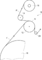
- Drawing 1 is a figure showing an example of the pasting device of the present invention conceptually.
- FIG. 2 is a conceptual diagram for explaining the bonding apparatus shown in FIG. 1.
- Drawing 3 is a key map for explaining another example of the pasting device of the present invention.
- FIG. 1 an example of the bonding apparatus of this invention which implements the bonding method of this invention is shown notionally.
- the laminating apparatus 10 shown in FIG. 1 laminates the protective film P on the functional film F while conveying the long functional film F and the long protective film P in synchronization with the longitudinal direction. It is to paste.
- the functional film F corresponds to the first film of the present invention
- the protective film P corresponds to the second film of the present invention.
- the first film is wound around the bonding roller before the second film
- the second film is wound around the bonding roller at the bonding position. The first film and the second film are bonded to each other.
- the functional film F is a film that exhibits desired functions such as gas barrier properties, light diffusion properties, and antifogging properties.
- the functional film F is a laminated film in which a functional layer that expresses a target function such as a gas barrier layer is formed on the surface of a support (substrate, base material) made of a resin film or the like.
- the functional film F include light diffusion films, antireflection films, polarizing films, optical films such as wavelength conversion films and color filters, gas barrier films, antifogging films, and antifouling films.
- the protective film P is a film that is laminated and bonded to the surface of the functional layer of the functional film F in order to protect the functional layer.
- various known protective films laminate films
- a polyethylene film and a polypropylene film can be used as the protective film P.
- the first film is not limited to the functional film F
- the second film is not limited to the protective film P.
- the first film may be a resin film or a metal film that serves as a support for the functional film
- the second film may be a protective film that protects the surface of the resin film or the metal film.
- both the first film and the second film may be a resin film or a metal film
- the first film may be a metal film
- the second film may be a resin film.
- both the first film and the second film may be functional films.
- the first film may be a protective film P
- the second film may be a functional film F.
- the film to be protected is usually applied to the bonding roller first. It becomes the 1st film to wind.
- the first film and the second film are not particularly limited, and various kinds of long film materials (webs, sheet materials) can be used.
- At least one of the functional film F (first film) and the protective film P (second film) to be bonded in the present invention has an adhesive (adhesive layer) for improving adhesion.
- an adhesive adhesive layer
- Various types of known pressure-sensitive adhesives that are used for bonding sheet-like materials can be used depending on the forming material of the functional film F and the protective film P.
- the bonding apparatus 10 includes a bonding roller 12 and an introduction roller 14.
- the long functional film F is supplied to the laminating roller 12 after being subjected to processing such as film formation on the surface while being supported and conveyed at a predetermined position by the drum 18. That is, in the illustrated example, the drum 18 is a supply means in the present invention.
- the drum 18 is a supply means in the present invention.
- the functional film F is applied during conveyance by the drum 18.
- film formation of a functional layer application of paints and compositions, drying of applied paints, ultraviolet irradiation, plasma irradiation, heating or cooling, etc. are exemplified.
- the functional film F does not have to be subjected to any processing during conveyance by the drum 18. That is, the drum 18 may act only as a supply unit that supplies the functional film F to the laminating roller 12. Alternatively, a pass roller (guide roller) for supplying the functional film F to the bonding roller 12 may be used instead of the drum 18.
- the long protective film P is loaded into the laminating apparatus 10 as a protective film roll 16 wound in a roll shape.
- the protective film P is fed from the protective film roll 16 and is guided by the introduction roller 14 while being fed in synchronization with the functional film F, and is supplied to the bonding roller 12.
- the protective film P supplied to the bonding roller 12 is stacked on the functional film F previously wound around the bonding roller 12, and the functional film F and the protective film P are bonded together.
- the functional film F previously wound around the bonding roller 12 means that the upstream side of the position where the protective film P is wound around the bonding roller 12 in the film transport direction by the bonding roller 12. This means that the functional film F is wound around the laminating roller 12.
- the functional film F is necessarily on the bonding roller 12 side (lower side) with respect to the protective film.
- the film laminate S which is a laminate of the functional film F and the protective film P bonded by the bonding roller 12, is conveyed by the bonding roller 12, and is separated from the bonding roller 12 at a predetermined position. Then, it is guided by the pass roller 20 and conveyed downstream.
- upstream and downstream correspond to the film transport direction.
- the bonding method and the bonding apparatus of this invention are demonstrated in detail.
- the functional film F is supplied to the laminating roller 12 by the drum 18.
- the protective film P is supplied to the bonding roller 12 by the introduction roller 14, and is stacked and bonded to the functional film F previously wound around the bonding roller 12.
- the position where the protective film P (second film) is separated from the introduction roller 14 is the first separation position a, and the functional film F (first film) and the protective film in the bonding roller 12.
- the bonding position with P is the bonding position b
- the distance L1 between the first separation position a and the bonding position b falls within a predetermined distance range.
- the bonding position of the functional film F and the protective film P in the bonding roller 12 is, in other words, the most upstream position where the functional film F and the protective film P are stacked in the bonding roller 12. That is, the bonding position of the functional film F and the protective film P in the bonding roller 12 is the most upstream position where the functional film F and the protective film P are in contact with each other in the bonding roller 12.
- the distance L1 between the first separation position a and the bonding position b is expressed by the following formula: 0 ⁇ L1 ⁇ [(2.7 ⁇ 10 ⁇ 6 ⁇ W ⁇ E ⁇ tw 3 ) / T] 1/2 Meet.
- the present invention does not use a nip roller that sandwiches the functional film F and the protective film P at the bonding position b, and the distance L1 satisfies “0 ⁇ L1 ⁇ Lu”.
- Functional film F (functional layer) damage due to sliding contact with P, deterioration of surface properties of functional film F (functional layer) due to wrinkles of protective film P, deformation, damage, etc. are prevented and functionality is prevented. Bonding of the film F and the protective film P can be performed.
- a nip roller that sandwiches and conveys the two films at the bonding position is usually used.
- a speed difference occurs between the two films due to crushing of the nip roller at the bonding position, crushing of the film, etc., and the functional film F is caused by sliding contact between the films. May damage the functional layer. If the film of the functional film F and the protective film P is bonded without using a nip roller, film damage due to sliding contact between the films can be prevented.
- the protective film P is wrinkled by the tension applied to the protective film P.
- the protective film P is bonded to the functional film F with wrinkles and the film laminate S is sandwiched and / or wound, the wrinkles contact and press the wrinkles of the protective film P to function. May be transferred to the functional layer of the functional film F, and the surface properties of the functional layer may deteriorate.
- the wrinkles of the protective film P may come into contact with the functional layer and be pressed to cause damage or deformation of the functional layer.
- the present inventors when performing bonding of the functional film F and the protective film P without using a nip roller, perform bonding of the functional film F and the protective film P on the peripheral surface.
- the bonding roller 12 and the introducing roller 14 are brought close to each other without contact, so that the protective film is caused by the tension. It has been found that wrinkles can be prevented from occurring in P.
- the surface properties of the functional layer of the functional film F deteriorate due to the wrinkles of the protective film P, Deformation and damage can be prevented.
- the distance L1 exceeds the upper limit distance Lu, wrinkles of the protective film P caused by tension cannot be sufficiently prevented.
- the distance L1 is 95 of upper limit distance Lu at the point which can prevent the wrinkle of the protective film P resulting from a tension
- the distance L1 is the thickness of the functional film F (first film), the protective film P (thickness of the second film), It is preferable that the distance exceeds the total of the deflection of the introduction roller 14 and the deflection of the bonding roller 12.
- the distance L1 preferably satisfies “L1> the thickness of the functional film F + the thickness of the protective film P + the deflection of the introduction roller 14 + the deflection of the bonding roller 12”.
- “the total of the thickness of the functional film F, the thickness of the protective film P, the deflection of the introduction roller 14 and the deflection of the bonding roller 12” is also referred to as “total distance”.
- the distance L1 is more preferably twice or more of the total distance, and further preferably four or more times.
- the distance L1 By setting the distance L1 to a distance exceeding the total distance, in particular, twice or more the total distance, production errors and fluctuations in the diameters of the bonding roller 12 and the introduction roller 14, the thicknesses of the functional film F and the protective film P Even when unevenness or the like occurs, it is possible to reliably prevent the introduction roller 14 from contacting the film laminate S (protective film P) in which the functional film F and the protective film P are bonded at the bonding position b. The same inconvenience as that of the nip roller can be prevented more reliably.
- the functional film F (first film) and the protective film P (second film) are not particularly limited, and various known long films can be used. is there. Accordingly, there is no particular limitation on the thickness, width and Young's modulus of the functional film F and the protective film P. Furthermore, the conveyance speed and applied tension of the functional film F and the protective film P may be appropriately set according to the material of each film, required productivity, processing conditions in the upstream drum 18 and the like.
- the distance L1 satisfies “0 ⁇ L1 ⁇ Lu”, the region where the functional film F is wound around the bonding roller 12, and the functional film F and the protective film P between the bonding roller 12 and There is no restriction
- the winding position c and the bonding position b are set. Is preferably 10 mm or more, more preferably 30 mm or more, and even more preferably 50 mm or more.
- the position where the functional film F winds around the bonding roller 12, that is, the winding position c is, in other words, the most upstream position where the functional film F contacts the bonding roller 12.
- the functional film F is wound around the bonding roller 12 before the protective film P. That is, the functional film F is wound around the bonding roller 12 from the upstream side of the bonding position b in the conveyance direction by the bonding roller 12.
- the functional film F is wrapped around the laminating roller 12 and conveyed before the protective film P, and then the protective film is applied to the functional film F at the laminating position b downstream from the winding position c. Stack P and paste.
- the functional film F comes into close contact with the laminating roller 12 to be in a stable state, and the functional film F and the protective film P can be bonded without generating wrinkles or the like.
- the distance L2 between the winding position c and the bonding position b to 10 mm or more, the state of the functional film F can be surely made stable, and more suitable functionality. Bonding of the film F and the protective film P becomes possible.
- the distance L3 is preferably 10 mm or more, more preferably 30 mm or more, and even more preferably 50 mm or more.
- the distance L3 is preferably set to this distance. That is, supply of the functional film F from the drum 18 to the bonding roller 12, supply of the protective film P from the introduction roller 14 to the bonding roller 12, and conveyance of the film laminate S by the bonding roller 12, that is, the pass roller 20.
- the film stack S is guided so that the distance L3 is 10 mm or more.
- the distance L3 10 mm or more the film laminate S can be separated from the laminating roller 12 after sufficiently stabilizing the contact state between the functional film F and the protective film P in the film laminate S.
- the radius of conveyance between the functional film F and the protective film P differs due to the thickness. Therefore, a slight speed difference arises in the conveyance speed of the functional film F in the film laminated body S and the protective film P between the bonding position b and the 2nd separation position d. Due to this, if the distance L3 is too long, conversely, the adhesion between the functional film F and the protective film P in the film laminate S may become unstable. Considering this point, the distance L3 between the bonding position b and the second separation position d is preferably 200 mm or less, and more preferably 100 mm or less. In this regard, the configuration using a nip roller 24 described later is the same.
- a nip roller 24 that is nipped and conveyed together with the bonding roller 12 may be provided.
- the distance L4 between the laminating position b and the nipping position e is 10 mm or more. It is preferable to set it as 50 mm or more. By setting the distance L4 to 10 mm or more, the functional film F and the protective film P can be sandwiched in a state where the bonding between the functional film F and the protective film P is sufficiently stable, and thus the adhesion is improved more appropriately. it can.
- the 2nd separation position d which separates the film laminated body S from the bonding roller 12 is downstream from the clamping position e, it will protect with the functional film F in the film laminated body S. Adhesion with the film P can be sufficiently secured. That is, when the nip roller 24 is used, sufficiently high adhesion can be ensured even if the distance L3 between the bonding position b and the second separation position d is shorter than the distance described above.
- Example 1 As a film (first film) simulating the functional film F, a polyethylene terephthalate film (PET film) having a width of 700 mm and a thickness of 50 ⁇ m was prepared.
- a protective film P (second film) prepared by applying a laminating adhesive on one side of a PET film having a width of 700 mm, a thickness of 23 ⁇ m, and a Young's modulus of 4000 MPa was prepared.
- Such functional film F and protective film P are bonded using the bonding apparatus 10 shown in FIGS. 1 and 2 while facing the functional film F and the surface coated with the laminating adhesive.
- a film laminate S was produced.
- the diameter of the introduction roller 14 was 50 mm, and the diameter of the bonding roller 12 was 150 mm.
- the tension applied to the functional film F and the protective film P was 100 N / m.
- the conveyance speed of the functional film F and the protective film P was 10 m / min.
- the distance L1 between the first separation position a and the bonding position b was 40 mm.
- the upper limit distance Lu (Lu [(2.7 ⁇ 10 ⁇ 6 ⁇ W ⁇ E ⁇ tw 3 ) / T] 1/2 ) under this condition is 60.5 mm.
- the distance L2 between the winding position c and the bonding position b was 50 mm, and the distance L3 between the bonding position b and the second separation position d was 80 mm.
- Examples 2 to 5, Comparative Examples 1 to 6 Distance L1 between first separation position a and bonding position b, thickness of protective film P (Example 3 and Comparative Example 3 (50 ⁇ m)), tension applied to protective film P (Example 4 and Comparative Example 4 (200N) / M)) and any of the widths of the functional film F and the protective film P (Example 5 and Comparative Example 6 (200 mm)) are the same as in Example 1 except that they are changed as shown in Table 1. Then, the functional film F and the protective film P were bonded together to produce a film laminate S.
- the distance L2 between the winding position c and the bonding position b and the distance L3 between the bonding position b and the second separation position d were set to be constant as in Example 1.
- the film laminate S thus produced was evaluated for wrinkles, scratches, and adhesion.
- [Wrinkle] Wrinkles of the film laminate S were evaluated by visual observation of the film laminate S and visual observation of the properties of the functional film F after the protective film P was peeled off. The evaluation is as follows. A: No wrinkles B: There are small wrinkles, but there is no damage to the functional film F C: There are wrinkles, and the functional film F is damaged
- the protective film P was peeled off, and the number of scratches on the surface of the functional film F was counted to evaluate the scratches.
- the evaluation is as follows. A: No scratch B: 1-10 scratches / m 2 C: No more than 11 scratches / m 2
- the upper limit distance Lu is 60.5 mm.
- Examples 1 and 2 in which the distance L1 (the distance L1 between the separation position a and the bonding position b) is equal to or less than the upper limit distance Lu are good in both wrinkles, scratches, and b adhesion.
- Example 1 (Examples 3 to 5) in which the distance L1 is 95% or less of the upper limit distance Lu can more appropriately suppress the occurrence of wrinkles.
- Comparative Examples 1 and 2 in which the distance L1 exceeds the upper limit distance Lu wrinkles occurred. As shown in Example 3 and Comparative Example 4, when the protective film becomes thicker, the upper limit distance Lu becomes longer.
- Example 3 even if the distance L1 is 80 mm, which is the same as in Comparative Example 2, the occurrence of wrinkles can be prevented because the distance L1 is not more than the upper limit distance Lu. However, in Comparative Example 3 in which the distance L1 was longer than the upper limit distance Lu under the same conditions, wrinkles occurred. When the tension applied to the protective film P is increased, the upper limit distance Lu is shortened. Therefore, in Comparative Example 4 in which the distance L1 is 60 mm, which is the same as that in Example 2, the distance L1 exceeds the upper limit distance, and thus wrinkles are generated. On the other hand, in Example 4 in which the distance L1 is 40 mm, the generation of wrinkles can be prevented because the distance L1 is equal to or less than the upper limit distance Lu.
- Comparative Example 5 in which the distance L1 is 0 mm, similarly to the case where a nip roller is provided at the bonding position b, a transport speed difference occurs between the functional film F and the protective film P, and the functional film F is scratched. Has occurred. Moreover, when the width
- Example 6 As shown in FIG. 3, the functional film F and the protective film P are provided in the same manner as in Example 1 except that a nip roller 24 that sandwiches and conveys the film laminate S together with the bonding roller 12 is provided downstream of the bonding position b.
- the film laminated body S was produced. That is, also in this example, the upper limit distance Lu is 60.5 mm, and the distance L1 between the first separation position a and the bonding position b is 40 mm.
- the distance L4 between the bonding position b and the clamping position e was 30 mm, and the clamping force of the film laminate S formed by the bonding roller 12 and the nip roller 24 was 50N.
- the produced film laminate S was evaluated for wrinkles, scratches, and adhesion as in Example 1. As a result, the evaluation of wrinkles was A, and the evaluation of scratches was A. Further, the adhesion was particularly high, and the evaluation was AA. The results are also shown in the above table. From the above results, the effects of the present invention are clear.
Landscapes
- Engineering & Computer Science (AREA)
- Manufacturing & Machinery (AREA)
- Lining Or Joining Of Plastics Or The Like (AREA)
Abstract
2枚の長尺なフィルムをシワ等を生じることなく貼合することを課題とする。長尺な第1のフィルムと第2のフィルムとを長手方向に搬送しつつ貼合するに際し、両フィルムを貼合する貼合ローラと、貼合ローラに第2のフィルムを供給する導入ローラとを用い、導入ローラから第2のフィルムが離間する位置と、貼合ローラにおけるフィルムの貼合位置との距離を距離L1とし、第2のフィルムの張力をT、幅をW、ヤング率をE、厚さをtw、とした際に、距離L1が、『0<L1≦[(2.7×10⁻⁶×W×E×tw3)/T]1/2』を満たすことにより、課題を解決する。
Description
本発明は、長尺な2枚のフィルムを長手方向に搬送しつつ貼合する貼合方法、および、この貼合方法を実施する貼合装置に関する。
光学素子、液晶ディスプレイおよび有機EL(Electro Luminescence)ディスプレイ等の表示装置、半導体装置、ならびに、薄膜太陽電池などの各種の装置に、ガスバリアフィルム、カラーフィルタ、光拡散フィルム、および、反射防止フィルム等の機能性フィルムが利用されている。
これらの機能性フィルムは、一例として、支持体の表面に、塗布法、スパッタリングおよびプラズマCVD(Chemical Vapor Deposition)等の気相成膜法、ならびに、印刷法等の方法で、目的とする機能を発現する層(膜)を形成した構成を有する。以下の説明では、『目的とする機能を発現する層』を『機能層』とも言う。
このような機能性フィルムを効率良く製造する方法として、いわゆるロール・トゥ・ロール(Roll to Roll)が知られている。以下の説明では、『ロール・トゥ・ロール』を『RtoR』とも言う。
周知のように、RtoRとは、長尺な支持体(被成膜材料)を巻回してなるロールから、支持体を送り出して、長手方向に搬送しつつ、例えば気相成膜法によって機能層を形成し、その後、機能層を形成した支持体を、再度、ロール状に巻回する方法である。
周知のように、RtoRとは、長尺な支持体(被成膜材料)を巻回してなるロールから、支持体を送り出して、長手方向に搬送しつつ、例えば気相成膜法によって機能層を形成し、その後、機能層を形成した支持体を、再度、ロール状に巻回する方法である。
機能性フィルムに形成される機能層は、形成材料および厚さ等によっては、外力等によって容易に損傷してしまう場合が有る。例えば、RtoRでは、パスローラとの当接や、巻き取られた際の支持体との摺接によって、機能層が損傷してしまう場合がある。
このような場合には、機能層を形成した後、機能層がパスローラ等の他の部材に当接する前に、機能層の表面に保護フィルム(ラミネートフィルム)を積層して、機能性フィルムと保護フィルムとを貼合するのが好ましい。
このような場合には、機能層を形成した後、機能層がパスローラ等の他の部材に当接する前に、機能層の表面に保護フィルム(ラミネートフィルム)を積層して、機能性フィルムと保護フィルムとを貼合するのが好ましい。
例えば、特許文献1には、RtoRによる成膜装置(巻取式成膜装置)において、搬出・巻取室から成膜室に成膜用フィルムを送り出し、成膜室において成膜を行うと共に、保護フィルム繰出室から保護フィルムを繰り出して、成膜済の成膜フィルムに保護フィルムを積層して、密着機構で密着させた後、搬出・巻取室において巻き取る成膜装置が記載されている。
また、特許文献2には、第1の帯状シート(プラスチックフィルム)を送りローラに所定回転角度だけ巻掛けると共に、第1の帯状シートと第1の帯状シート上に供給される第2の帯状シート(保護用のプラスチックフィルム)とを重ねた状態で送りローラと押圧ローラとで挟圧して、貼合しながら送る帯状シート搬送装置が記載されている。
また、特許文献2には、第1の帯状シート(プラスチックフィルム)を送りローラに所定回転角度だけ巻掛けると共に、第1の帯状シートと第1の帯状シート上に供給される第2の帯状シート(保護用のプラスチックフィルム)とを重ねた状態で送りローラと押圧ローラとで挟圧して、貼合しながら送る帯状シート搬送装置が記載されている。
RtoRによって機能性フィルムと保護フィルムとを貼合する場合には、通常、特許文献2に記載されるように、ニップローラを用いて、機能性フィルムと保護フィルムとを挟持搬送することで、両フィルムを貼合して密着させる。
ところが、機能性フィルムと保護フィルムとを、ニップローラによって挟持しながら貼合すると、ローラの変形等に起因するフィルムの速度差によって、機能性フィルムと保護フィルムとが摺接してしまい、機能性フィルムの機能層に擦り傷が生じる場合がある。
ところが、機能性フィルムと保護フィルムとを、ニップローラによって挟持しながら貼合すると、ローラの変形等に起因するフィルムの速度差によって、機能性フィルムと保護フィルムとが摺接してしまい、機能性フィルムの機能層に擦り傷が生じる場合がある。
他方、特許文献1に記載されるように、ニップローラを用いずに、機能性フィルムと保護フィルムとを積層する方法も知られている。
ところが、この場合には、保護フィルムに掛かる張力等に起因して、保護フィルムにシワが生じてしまうという問題が有る。保護フィルムにシワが生じた状態で、機能性フィルムと貼合されると、積層体の挟持および積層体の巻回等によって、保護フィルムのシワが機能性フィルムの機能層に当接して押圧されることで、転写されてしまい、機能層の表面性状が悪化してしまう場合がある。また、機能層が薄い場合および脆い場合等には、保護フィルムのシワが機能層に当接して押圧されることにより、機能層の損傷および変形等が生じる場合も有る。
ところが、この場合には、保護フィルムに掛かる張力等に起因して、保護フィルムにシワが生じてしまうという問題が有る。保護フィルムにシワが生じた状態で、機能性フィルムと貼合されると、積層体の挟持および積層体の巻回等によって、保護フィルムのシワが機能性フィルムの機能層に当接して押圧されることで、転写されてしまい、機能層の表面性状が悪化してしまう場合がある。また、機能層が薄い場合および脆い場合等には、保護フィルムのシワが機能層に当接して押圧されることにより、機能層の損傷および変形等が生じる場合も有る。
本発明の目的は、このような従来技術の問題点を解決することにあり、RtoR等によって、2枚の長尺なフィルムを長手方向に搬送しつつ積層して貼合する際に、フィルムの摺接によるフィルムの損傷、一方のフィルムにシワが生じることに起因する他方のフィルムの表面性状の悪化および損傷等を防止できる、フィルムの貼合方法、および、この貼合方法を実施する貼合装置を提供することにある。
この目的を達成するために本発明の貼合方法は、長尺な第1のフィルムと長尺な第2のフィルムとを、長手方向に搬送しつつ貼合するに際し、
第1のフィルムと第2のフィルムとを貼合する貼合ローラ、および、貼合ローラに第2のフィルムを供給する導入ローラを用い、
導入ローラから第2のフィルムが離間する位置と、貼合ローラにおける第1のフィルムと第2のフィルムとの貼合位置との距離を距離L1とし、
第2のフィルムに掛かる張力をT、第2のフィルムの幅をW、第2のフィルムのヤング率をE、および、第2のフィルムの厚さをtwとした際に、
距離L1が、下記の式
0<L1≦[(2.7×10⁻⁶×W×E×tw3)/T]1/2
を満たすことを特徴とする貼合方法を提供する。
第1のフィルムと第2のフィルムとを貼合する貼合ローラ、および、貼合ローラに第2のフィルムを供給する導入ローラを用い、
導入ローラから第2のフィルムが離間する位置と、貼合ローラにおける第1のフィルムと第2のフィルムとの貼合位置との距離を距離L1とし、
第2のフィルムに掛かる張力をT、第2のフィルムの幅をW、第2のフィルムのヤング率をE、および、第2のフィルムの厚さをtwとした際に、
距離L1が、下記の式
0<L1≦[(2.7×10⁻⁶×W×E×tw3)/T]1/2
を満たすことを特徴とする貼合方法を提供する。
このような本発明の貼合方法において、距離L1を、第1のフィルムの厚さ、第2のフィルムの厚さ、導入ローラの振れ、および、貼合ローラの振れ、の合計を超える距離とするのが好ましい。
また、貼合ローラに第1のフィルムが巻き掛かる位置と、貼合ローラにおける第1のフィルムと第2のフィルムとの貼合位置との距離を距離L2とした際に、距離L2を10mm以上とするのが好ましい。
また、貼合ローラにおける第1のフィルムと第2のフィルムとの貼合位置と、第1のフィルムと第2のフィルムとを貼合した積層体が貼合ローラから離間する位置との距離を距離L3とした際に、距離L3を10mm以上とするのが好ましい。
また、さらに、貼合ローラにおける第1のフィルムと第2のフィルムとの貼合位置よりも下流において、第1のフィルムと第2のフィルムとを貼合した積層体を貼合ローラと共に挟持搬送するニップローラを用い、かつ、貼合ローラにおける第1のフィルムと第2のフィルムとの貼合位置と、貼合ローラとニップローラとによる第1のフィルムと第2のフィルムとを貼合した積層体の挟持位置との距離を距離L4とした際に、距離L4を10mm以上とするのが好ましい。
また、貼合ローラに第1のフィルムが巻き掛かる位置と、貼合ローラにおける第1のフィルムと第2のフィルムとの貼合位置との距離を距離L2とした際に、距離L2を10mm以上とするのが好ましい。
また、貼合ローラにおける第1のフィルムと第2のフィルムとの貼合位置と、第1のフィルムと第2のフィルムとを貼合した積層体が貼合ローラから離間する位置との距離を距離L3とした際に、距離L3を10mm以上とするのが好ましい。
また、さらに、貼合ローラにおける第1のフィルムと第2のフィルムとの貼合位置よりも下流において、第1のフィルムと第2のフィルムとを貼合した積層体を貼合ローラと共に挟持搬送するニップローラを用い、かつ、貼合ローラにおける第1のフィルムと第2のフィルムとの貼合位置と、貼合ローラとニップローラとによる第1のフィルムと第2のフィルムとを貼合した積層体の挟持位置との距離を距離L4とした際に、距離L4を10mm以上とするのが好ましい。
また、本発明の貼合装置は、長尺な第1のフィルムと長尺な第2のフィルムとを、長手方向に搬送しつつ貼合する貼合装置であって、
第1のフィルムと第2のフィルムとを貼合する貼合ローラと、貼合ローラに第2のフィルムを供給する導入ローラと、貼合ローラに第1のフィルムを供給する供給手段と、を有し、
導入ローラから第2のフィルムが離間する位置と、貼合ローラにおける第1のフィルムと第2のフィルムとの貼合位置との距離を距離L1とし、
第2のフィルムに掛かる張力をT、第2のフィルムの幅をW、第2のフィルムのヤング率をE、および、第2のフィルムの厚さをtwとした際に、
距離L1が、下記の式
0<L1≦[(2.7×10⁻⁶×W×E×tw3)/T]1/2
を満たすように、供給手段が貼合ローラに第1のフィルムを供給し、導入ローラが貼合ローラに第2のフィルムの供給することを特徴とする貼合装置を提供する。
第1のフィルムと第2のフィルムとを貼合する貼合ローラと、貼合ローラに第2のフィルムを供給する導入ローラと、貼合ローラに第1のフィルムを供給する供給手段と、を有し、
導入ローラから第2のフィルムが離間する位置と、貼合ローラにおける第1のフィルムと第2のフィルムとの貼合位置との距離を距離L1とし、
第2のフィルムに掛かる張力をT、第2のフィルムの幅をW、第2のフィルムのヤング率をE、および、第2のフィルムの厚さをtwとした際に、
距離L1が、下記の式
0<L1≦[(2.7×10⁻⁶×W×E×tw3)/T]1/2
を満たすように、供給手段が貼合ローラに第1のフィルムを供給し、導入ローラが貼合ローラに第2のフィルムの供給することを特徴とする貼合装置を提供する。
このような本発明の貼合装置において、距離L1が、第1のフィルムの厚さ、第2のフィルムの厚さ、導入ローラの振れ、および、貼合ローラの振れ、の合計を超える距離となるように、供給手段が貼合ローラに第1のフィルムを供給し、導入ローラが貼合ローラに第2のフィルムを供給するのが好ましい。
また、貼合ローラに第1のフィルムが巻き掛かる位置と、貼合ローラにおける第1のフィルムと第2のフィルムとの貼合位置との距離を距離L2とした際に、距離L2が10mm以上となるように、供給手段が貼合ローラに第1のフィルムを供給し、導入ローラが貼合ローラに第2のフィルムを供給するのが好ましい。
また、貼合ローラにおける第1のフィルムと第2のフィルムとの貼合位置と、第1のフィルムと第2のフィルムとを貼合した積層体が貼合ローラから離間する位置との距離を距離L3とした際に、距離L3が10mm以上となるように、供給手段が貼合ローラに第1のフィルムを供給し、導入ローラが貼合ローラに第2のフィルムを供給し、貼合ローラが第1のフィルムと第2のフィルムとを貼合した積層体を搬送するのが好ましい。
また、さらに、貼合ローラにおける第1のフィルムと第2のフィルムとの貼合位置よりも下流において、第1のフィルムと第2のフィルムとを貼合した積層体を貼合ローラと共に挟持搬送するニップローラを有し、貼合ローラにおける第1のフィルムと第2のフィルムとの貼合位置と、貼合ローラとニップローラとによる第1のフィルムと第2のフィルムとを貼合した積層体の挟持位置との距離を距離L4とした際に、距離L4が10mm以上となるように、供給手段が貼合ローラに第1のフィルムを供給し、導入ローラが貼合ローラに第2のフィルムを供給し、貼合ローラとニップローラとによる第1のフィルムと第2のフィルムとを貼合した積層体の挟持を行うのが好ましい。
また、貼合ローラに第1のフィルムが巻き掛かる位置と、貼合ローラにおける第1のフィルムと第2のフィルムとの貼合位置との距離を距離L2とした際に、距離L2が10mm以上となるように、供給手段が貼合ローラに第1のフィルムを供給し、導入ローラが貼合ローラに第2のフィルムを供給するのが好ましい。
また、貼合ローラにおける第1のフィルムと第2のフィルムとの貼合位置と、第1のフィルムと第2のフィルムとを貼合した積層体が貼合ローラから離間する位置との距離を距離L3とした際に、距離L3が10mm以上となるように、供給手段が貼合ローラに第1のフィルムを供給し、導入ローラが貼合ローラに第2のフィルムを供給し、貼合ローラが第1のフィルムと第2のフィルムとを貼合した積層体を搬送するのが好ましい。
また、さらに、貼合ローラにおける第1のフィルムと第2のフィルムとの貼合位置よりも下流において、第1のフィルムと第2のフィルムとを貼合した積層体を貼合ローラと共に挟持搬送するニップローラを有し、貼合ローラにおける第1のフィルムと第2のフィルムとの貼合位置と、貼合ローラとニップローラとによる第1のフィルムと第2のフィルムとを貼合した積層体の挟持位置との距離を距離L4とした際に、距離L4が10mm以上となるように、供給手段が貼合ローラに第1のフィルムを供給し、導入ローラが貼合ローラに第2のフィルムを供給し、貼合ローラとニップローラとによる第1のフィルムと第2のフィルムとを貼合した積層体の挟持を行うのが好ましい。
本発明によれば、RtoR等によって、2枚の長尺なフィルムを長手方向に搬送しつつ積層して貼合する際に、フィルムの摺接によるフィルムの損傷、一方のフィルムにシワが生じることに起因する他方のフィルムの表面性状の悪化および損傷等を防止できる。
以下、本発明の貼合方法および貼合装置について、添付の図面に示される好適実施例を基に、詳細に説明する。
図1に、本発明の貼合方法を実施する、本発明の貼合装置の一例を概念的に示す。
図1に示す貼合装置10は、長尺な機能性フィルムFと長尺な保護フィルムPとを、長手方向に同期して搬送しつつ、機能性フィルムFに保護フィルムPを積層して、貼合するものである。
貼合装置10において、機能性フィルムFは本発明の第1のフィルムに対応し、保護フィルムPは本発明の第2のフィルムに対応する。後述するが、本発明においては、第1のフィルムの方が第2のフィルムよりも先に貼合ローラに巻き掛かり、第2のフィルムは、貼合位置において貼合ローラに巻き掛かって第1のフィルムに積層されて、第1のフィルムと第2のフィルムとが貼合される。
図1に示す貼合装置10は、長尺な機能性フィルムFと長尺な保護フィルムPとを、長手方向に同期して搬送しつつ、機能性フィルムFに保護フィルムPを積層して、貼合するものである。
貼合装置10において、機能性フィルムFは本発明の第1のフィルムに対応し、保護フィルムPは本発明の第2のフィルムに対応する。後述するが、本発明においては、第1のフィルムの方が第2のフィルムよりも先に貼合ローラに巻き掛かり、第2のフィルムは、貼合位置において貼合ローラに巻き掛かって第1のフィルムに積層されて、第1のフィルムと第2のフィルムとが貼合される。
機能性フィルムFとは、ガスバリア性、光拡散性および防曇性等の目的とする機能を発現するフィルムである。機能性フィルムFは、一例として、樹脂フィルム等からなる支持体(基板、基材)の表面に、ガスバリア層等の目的とする機能を発現する機能層を形成してなる積層フィルムである。
機能性フィルムFとしては、例えば、光拡散フィルム、反射防止フィルム、偏光フィルム、波長変換フィルムおよびカラーフィルタ等の光学フィルム、ガスバリアフィルム、防曇フィルム、ならびに、防汚フィルム等が例示される。
機能性フィルムFとしては、例えば、光拡散フィルム、反射防止フィルム、偏光フィルム、波長変換フィルムおよびカラーフィルタ等の光学フィルム、ガスバリアフィルム、防曇フィルム、ならびに、防汚フィルム等が例示される。
他方、保護フィルムPは、機能層を保護するために、機能性フィルムFの機能層の表面に積層され、貼合されるフィルムである。保護フィルムPとしては、ポリエチレンフィルムおよびポリプロピレンフィルム等の公知の保護フィルム(ラミネートフィルム)が、各種、利用可能である。
なお、本発明においては、第1のフィルムは機能性フィルムFに限定はされず、また、第2のフィルムは保護フィルムPに限定はされない。
例えば、第1のフィルムが機能性フィルムの支持体となる樹脂フィルムまたは金属フィルムで、第2のフィルムが樹脂フィルムまたは金属フィルムの表面を保護する保護フィルムであってもよい。あるいは、第1のフィルムおよび第2のフィルムが、共に、樹脂フィルムまたは金属フィルムであってもよく、第1のフィルムが金属フィルムで第2のフィルムが樹脂フィルムであってもよい。あるいは、第1のフィルムおよび第2のフィルムが、共に、機能性フィルムであってもよい。
また、第1のフィルムが保護フィルムPで、第2のフィルムが機能性フィルムFであってもよい。但し、貼合される2枚のフィルムのうち、一方が保護されるフィルムで、もう一方が他方を保護する保護フィルムである場合には、通常、保護されるフィルムが、先に貼合ローラに巻き掛かる第1のフィルムとなる。
例えば、第1のフィルムが機能性フィルムの支持体となる樹脂フィルムまたは金属フィルムで、第2のフィルムが樹脂フィルムまたは金属フィルムの表面を保護する保護フィルムであってもよい。あるいは、第1のフィルムおよび第2のフィルムが、共に、樹脂フィルムまたは金属フィルムであってもよく、第1のフィルムが金属フィルムで第2のフィルムが樹脂フィルムであってもよい。あるいは、第1のフィルムおよび第2のフィルムが、共に、機能性フィルムであってもよい。
また、第1のフィルムが保護フィルムPで、第2のフィルムが機能性フィルムFであってもよい。但し、貼合される2枚のフィルムのうち、一方が保護されるフィルムで、もう一方が他方を保護する保護フィルムである場合には、通常、保護されるフィルムが、先に貼合ローラに巻き掛かる第1のフィルムとなる。
すなわち、本発明において、第1のフィルムおよび第2のフィルムには、特に制限はなく、長尺なフィルム状物(ウエブ、シート状物)が、各種、利用可能である。
本発明で貼合する機能性フィルムF(第1のフィルム)および保護フィルムP(第2のフィルム)は、少なくとも一方が、密着性を向上させるための粘着剤(粘着層)を有してもよい。
粘着剤も、機能性フィルムFおよび保護フィルムPの形成材料等に応じて、シート状物の貼合に利用される公知の粘着剤が、各種、利用可能である。
粘着剤も、機能性フィルムFおよび保護フィルムPの形成材料等に応じて、シート状物の貼合に利用される公知の粘着剤が、各種、利用可能である。
貼合装置10は、貼合ローラ12と、導入ローラ14とを有する。
貼合装置10において、長尺な機能性フィルムFは、ドラム18で所定位置に支持されて搬送されつつ、表面に成膜等の処理を施されて、貼合ローラ12に供給される。すなわち、図示例においては、ドラム18が本発明における供給手段となる。
このように、機能性フィルムFの搬送方向において、機能性フィルムFに処理を施すドラム18の直下流に貼合ローラ12を配置することで、パスローラとの接触による機能層の損傷等を防止して、機能性フィルムFと保護フィルムPとの貼合を行うことができる。
貼合装置10において、長尺な機能性フィルムFは、ドラム18で所定位置に支持されて搬送されつつ、表面に成膜等の処理を施されて、貼合ローラ12に供給される。すなわち、図示例においては、ドラム18が本発明における供給手段となる。
このように、機能性フィルムFの搬送方向において、機能性フィルムFに処理を施すドラム18の直下流に貼合ローラ12を配置することで、パスローラとの接触による機能層の損傷等を防止して、機能性フィルムFと保護フィルムPとの貼合を行うことができる。
ドラム18による搬送中に機能性フィルムFが施される処理には、特に制限は無い。具体的には、機能層等の成膜、塗料および組成物等の塗布、塗布された塗料等の乾燥、紫外線照射、プラズマ照射、ならびに、加熱または冷却等が例示される。
なお、機能性フィルムFは、ドラム18による搬送中に、何も処理を施されなくてもよい。すなわち、ドラム18は機能性フィルムFを貼合ローラ12に供給する供給手段としてのみ作用するものであってもよい。あるいは、ドラム18に変えて、機能性フィルムFを貼合ローラ12に供給するためのパスローラ(ガイドローラ)を用いてもよい。
なお、機能性フィルムFは、ドラム18による搬送中に、何も処理を施されなくてもよい。すなわち、ドラム18は機能性フィルムFを貼合ローラ12に供給する供給手段としてのみ作用するものであってもよい。あるいは、ドラム18に変えて、機能性フィルムFを貼合ローラ12に供給するためのパスローラ(ガイドローラ)を用いてもよい。
一方、長尺な保護フィルムPは、ロール状に巻回された保護フィルムロール16として貼合装置10に装填される。
保護フィルムPは、保護フィルムロール16から送り出され、機能性フィルムFと同期して搬送されつつ、導入ローラ14によって案内されて、貼合ローラ12に供給される。貼合ローラ12に供給された保護フィルムPは、先に貼合ローラ12に巻き掛かっている機能性フィルムFに積み重ねられ、機能性フィルムFと保護フィルムPとが貼合される。
なお、『先に貼合ローラ12に巻き掛かっている機能性フィルムF』とは、貼合ローラ12によるフィルムの搬送方向において、保護フィルムPが貼合ローラ12に巻き掛かる位置よりも上流側から、機能性フィルムFが貼合ローラ12に巻き掛かっている、という意味である。従って、貼合ローラ12の上では、必ず、機能性フィルムFが保護フィルムよりも貼合ローラ12側(下側)になる。
貼合ローラ12で貼合された、機能性フィルムFと保護フィルムPとを積み重ねて貼合したフィルム積層体Sは、貼合ローラ12によって搬送されて、所定位置で貼合ローラ12から離間して、パスローラ20によって案内されて、下流に搬送される。本発明において、上流および下流とは、フィルムの搬送方向に対応する。
保護フィルムPは、保護フィルムロール16から送り出され、機能性フィルムFと同期して搬送されつつ、導入ローラ14によって案内されて、貼合ローラ12に供給される。貼合ローラ12に供給された保護フィルムPは、先に貼合ローラ12に巻き掛かっている機能性フィルムFに積み重ねられ、機能性フィルムFと保護フィルムPとが貼合される。
なお、『先に貼合ローラ12に巻き掛かっている機能性フィルムF』とは、貼合ローラ12によるフィルムの搬送方向において、保護フィルムPが貼合ローラ12に巻き掛かる位置よりも上流側から、機能性フィルムFが貼合ローラ12に巻き掛かっている、という意味である。従って、貼合ローラ12の上では、必ず、機能性フィルムFが保護フィルムよりも貼合ローラ12側(下側)になる。
貼合ローラ12で貼合された、機能性フィルムFと保護フィルムPとを積み重ねて貼合したフィルム積層体Sは、貼合ローラ12によって搬送されて、所定位置で貼合ローラ12から離間して、パスローラ20によって案内されて、下流に搬送される。本発明において、上流および下流とは、フィルムの搬送方向に対応する。
以下、図1の部分拡大図である図2を参照して、本発明の貼合方法および貼合装置について、詳細に説明する。
前述のように、機能性フィルムFは、ドラム18によって貼合ローラ12に供給される。他方、保護フィルムPは、導入ローラ14によって貼合ローラ12に供給され、先に貼合ローラ12に巻き掛かっている機能性フィルムFに積み重ねられ、貼合される。
前述のように、機能性フィルムFは、ドラム18によって貼合ローラ12に供給される。他方、保護フィルムPは、導入ローラ14によって貼合ローラ12に供給され、先に貼合ローラ12に巻き掛かっている機能性フィルムFに積み重ねられ、貼合される。
ここで、本発明においては、導入ローラ14から保護フィルムP(第2のフィルム)が離間する位置を第1離間位置a、貼合ローラ12における機能性フィルムF(第1のフィルム)と保護フィルムPとの貼合位置を貼合位置bとした場合に、第1離間位置aと貼合位置bとの距離L1が、所定の距離の範囲に入る。
なお、貼合ローラ12における機能性フィルムFと保護フィルムPとの貼合位置とは、言い換えれば、貼合ローラ12において機能性フィルムFと保護フィルムPとが積み重ねられる最上流の位置である。すなわち、貼合ローラ12における機能性フィルムFと保護フィルムPとの貼合位置とは、貼合ローラ12において機能性フィルムFと保護フィルムPとが接触する最上流の位置である。
なお、貼合ローラ12における機能性フィルムFと保護フィルムPとの貼合位置とは、言い換えれば、貼合ローラ12において機能性フィルムFと保護フィルムPとが積み重ねられる最上流の位置である。すなわち、貼合ローラ12における機能性フィルムFと保護フィルムPとの貼合位置とは、貼合ローラ12において機能性フィルムFと保護フィルムPとが接触する最上流の位置である。
具体的には、保護フィルムPに掛かる張力をT、保護フィルムPの幅をW、保護フィルムPのヤング率をE、および、保護フィルムPの厚さをtw、とした際に、
第1離間位置aと貼合位置bとの距離L1は、下記の式
0<L1≦[(2.7×10⁻⁶×W×E×tw3)/T]1/2
を満たす。
以下の説明では、[(2.7×10⁻⁶×W×E×tw3)/T]1/2で算出される距離を上限距離Luとも言う(Lu=[(2.7×10-6×W×E×tw3)/T]1/2)。すなわち、本発明において、第1離間位置aと貼合位置bとの距離L1は、『0<L1≦Lu』を満たす。
第1離間位置aと貼合位置bとの距離L1は、下記の式
0<L1≦[(2.7×10⁻⁶×W×E×tw3)/T]1/2
を満たす。
以下の説明では、[(2.7×10⁻⁶×W×E×tw3)/T]1/2で算出される距離を上限距離Luとも言う(Lu=[(2.7×10-6×W×E×tw3)/T]1/2)。すなわち、本発明において、第1離間位置aと貼合位置bとの距離L1は、『0<L1≦Lu』を満たす。
本発明は、貼合位置bにおいて機能性フィルムFと保護フィルムPとを挟持するニップローラを用いず、かつ、距離L1が『0<L1≦Lu』を満たすことにより、機能性フィルムFと保護フィルムPとの摺接による機能性フィルムF(機能層)の損傷、保護フィルムPのシワに起因する機能性フィルムF(機能層)の表面性状の悪化、変形および損傷等を防止して、機能性フィルムFと保護フィルムPとの貼合を行うことができる。
前述のように、長尺な機能性フィルムFと保護フィルムPを搬送しつつ貼合する場合には、通常、貼合位置において2枚のフィルムを挟持搬送するニップローラを用いる。しかしながら、ニップローラを用いてフィルムを貼合すると、貼合位置におけるニップローラの潰れ、フィルムの潰れ等に起因して、両フィルムに速度差が生じてしまい、フィルム同士の摺接によって、機能性フィルムFの機能層が損傷してしまう可能性がある。
ニップローラを用いずに機能性フィルムFと保護フィルムPとのフィルムの貼合を行えば、フィルム同士の摺接に起因するフィルムの損傷は防止できる。しかしながら、ニップローラを用いずに機能性フィルムFと保護フィルムPとの貼合を行うと、保護フィルムPに掛かる張力によって、保護フィルムPにシワが生じてしまう。保護フィルムPにシワが有る状態で機能性フィルムFに貼合して、フィルム積層体Sの挟持搬送および/または巻回等を行うと、シワの当接および押圧によって保護フィルムPのシワが機能性フィルムFの機能層に転写されてしまい、機能層の表面性状が悪化してしまう場合がある。また、機能層が薄い場合および脆い場合等には、保護フィルムPのシワが機能層に当接して、押圧されることにより、機能層の損傷および変形等が生じる場合も有る。
ニップローラを用いずに機能性フィルムFと保護フィルムPとのフィルムの貼合を行えば、フィルム同士の摺接に起因するフィルムの損傷は防止できる。しかしながら、ニップローラを用いずに機能性フィルムFと保護フィルムPとの貼合を行うと、保護フィルムPに掛かる張力によって、保護フィルムPにシワが生じてしまう。保護フィルムPにシワが有る状態で機能性フィルムFに貼合して、フィルム積層体Sの挟持搬送および/または巻回等を行うと、シワの当接および押圧によって保護フィルムPのシワが機能性フィルムFの機能層に転写されてしまい、機能層の表面性状が悪化してしまう場合がある。また、機能層が薄い場合および脆い場合等には、保護フィルムPのシワが機能層に当接して、押圧されることにより、機能層の損傷および変形等が生じる場合も有る。
ここで、本発明者らは、ニップローラを用いずに機能性フィルムFと保護フィルムPとの貼合を行う際に、周面上で機能性フィルムFと保護フィルムPとの貼合を行う貼合ローラ12と、貼合ローラ12に保護フィルムPを供給する導入ローラ14とを用い、貼合ローラ12と導入ローラ14とを、接触することなく近接させることで、張力に起因して保護フィルムPにシワが生じることを防止できることを見出した。
具体的には、導入ローラ14から保護フィルムPが離間する第1離間位置aと、貼合ローラ12における両フィルムの貼合位置bとの距離L1を、『Lu=[(2.7×10⁻⁶×W×E×tw3)/T]1/2』で算出される上限距離Lu以下で、かつ、0超とすることにより、張力に起因する保護フィルムPのシワを防止して、保護フィルムPのシワが無い状態で、機能性フィルムFと保護フィルムPとを貼合できる。その結果、本発明によれば、貼合位置bでニップローラを用いることに起因する機能層の損傷に加え、保護フィルムPのシワに起因する、機能性フィルムFの機能層の表面性状の悪化、変形および損傷を防止できる。
具体的には、導入ローラ14から保護フィルムPが離間する第1離間位置aと、貼合ローラ12における両フィルムの貼合位置bとの距離L1を、『Lu=[(2.7×10⁻⁶×W×E×tw3)/T]1/2』で算出される上限距離Lu以下で、かつ、0超とすることにより、張力に起因する保護フィルムPのシワを防止して、保護フィルムPのシワが無い状態で、機能性フィルムFと保護フィルムPとを貼合できる。その結果、本発明によれば、貼合位置bでニップローラを用いることに起因する機能層の損傷に加え、保護フィルムPのシワに起因する、機能性フィルムFの機能層の表面性状の悪化、変形および損傷を防止できる。
距離L1が上限距離Luを超えると、張力に起因して生じる保護フィルムPのシワを十分に防止できない。
また、張力に起因する保護フィルムPのシワをより好適に防止できる、貼合装置の小型化を図れる、保護フィルムPが外乱を受けにくくなる等の点で、距離L1は、上限距離Luの95%以下とするのが好ましい。
また、張力に起因する保護フィルムPのシワをより好適に防止できる、貼合装置の小型化を図れる、保護フィルムPが外乱を受けにくくなる等の点で、距離L1は、上限距離Luの95%以下とするのが好ましい。
一方、距離L1が0では、貼合位置bにおいてニップローラによって機能性フィルムFと保護フィルムPとを貼合した場合と同じ状態になってしまい、前述のように、搬送速度差に起因する摺接によって、機能性フィルムFの機能層が損傷してしまう。
ニップローラによる貼合と同様の不都合を、より確実に防止するためには、距離L1は、機能性フィルムF(第1のフィルム)の厚さ、保護フィルムP(第2のフィルムの厚さ)、導入ローラ14の振れ、および、貼合ローラ12の振れ、の合計を超える距離とするのが好ましい。すなわち、距離L1は『L1>機能性フィルムFの厚さ+保護フィルムPの厚さ+導入ローラ14の振れ+貼合ローラ12の振れ』を満たすのが好ましい。
以下の説明では、『機能性フィルムFの厚さ、保護フィルムPの厚さ、導入ローラ14の振れ、および、貼合ローラ12の振れの合計』を『合計距離』とも言う。
特に、距離L1は、合計距離の2倍以上とするのがより好ましく、4倍以上とするのがさらに好ましい。
距離L1を、合計距離を超える距離、特に、合計距離の2倍以上とすることにより、貼合ローラ12および導入ローラ14の直径の製作誤差および振れ、機能性フィルムFおよび保護フィルムPの厚さムラ等が生じた場合でも、貼合位置bにおいて、導入ローラ14が機能性フィルムFと保護フィルムPとを貼合したフィルム積層体S(保護フィルムP)に接触することを確実に防止して、ニップローラによる貼合と同様の不都合を、さらに確実に防止できる。
ニップローラによる貼合と同様の不都合を、より確実に防止するためには、距離L1は、機能性フィルムF(第1のフィルム)の厚さ、保護フィルムP(第2のフィルムの厚さ)、導入ローラ14の振れ、および、貼合ローラ12の振れ、の合計を超える距離とするのが好ましい。すなわち、距離L1は『L1>機能性フィルムFの厚さ+保護フィルムPの厚さ+導入ローラ14の振れ+貼合ローラ12の振れ』を満たすのが好ましい。
以下の説明では、『機能性フィルムFの厚さ、保護フィルムPの厚さ、導入ローラ14の振れ、および、貼合ローラ12の振れの合計』を『合計距離』とも言う。
特に、距離L1は、合計距離の2倍以上とするのがより好ましく、4倍以上とするのがさらに好ましい。
距離L1を、合計距離を超える距離、特に、合計距離の2倍以上とすることにより、貼合ローラ12および導入ローラ14の直径の製作誤差および振れ、機能性フィルムFおよび保護フィルムPの厚さムラ等が生じた場合でも、貼合位置bにおいて、導入ローラ14が機能性フィルムFと保護フィルムPとを貼合したフィルム積層体S(保護フィルムP)に接触することを確実に防止して、ニップローラによる貼合と同様の不都合を、さらに確実に防止できる。
なお、導入ローラ14の振れ、および、貼合ローラ12の振れは、ダイヤルゲージ等の接触式の変位測定器によって求めればよい。
前述のように、本発明において、機能性フィルムF(第1のフィルム)および保護フィルムP(第2のフィルム)には、特に制限は無く、公知の長尺なフィルムが、各種、利用可能である。従って、機能性フィルムFおよび保護フィルムPの厚さ、幅およびヤング率にも、特に制限は無い。
さらに、機能性フィルムFおよび保護フィルムPの搬送速度および掛かる張力も、各フィルムの材料、要求される生産性、上流のドラム18等における処理条件等に応じて、適宜、設定すればよい。
さらに、機能性フィルムFおよび保護フィルムPの搬送速度および掛かる張力も、各フィルムの材料、要求される生産性、上流のドラム18等における処理条件等に応じて、適宜、設定すればよい。
本発明においては、距離L1が『0<L1≦Lu』を満たせば、貼合ローラ12に機能性フィルムFを巻き掛ける領域、および、貼合ローラ12に機能性フィルムFと保護フィルムPとのフィルム積層体Sを巻き掛ける領域には、特に制限はない。
ここで、貼合ローラ12への機能性フィルムFの巻き掛けは、貼合ローラ12に機能性フィルムFが巻き掛かる位置を巻き掛け位置cとした際に、巻き掛け位置cと貼合位置bとの距離L2を10mm以上とするのが好ましく、30mm以上とするのがより好ましく、50mm以上とするのがさらに好ましい。
すなわち、ドラム18から貼合ローラ12への機能性フィルムFの供給、および、導入ローラ14から貼合ローラ12への保護フィルムPの供給を、距離L2が10mm以上となるように行うのが好ましい。
なお、貼合ローラ12に機能性フィルムFが巻き掛かる位置すなわち巻き掛け位置cとは、言い換えれば、貼合ローラ12に機能性フィルムFが接触する最上流の位置である。
ここで、貼合ローラ12への機能性フィルムFの巻き掛けは、貼合ローラ12に機能性フィルムFが巻き掛かる位置を巻き掛け位置cとした際に、巻き掛け位置cと貼合位置bとの距離L2を10mm以上とするのが好ましく、30mm以上とするのがより好ましく、50mm以上とするのがさらに好ましい。
すなわち、ドラム18から貼合ローラ12への機能性フィルムFの供給、および、導入ローラ14から貼合ローラ12への保護フィルムPの供給を、距離L2が10mm以上となるように行うのが好ましい。
なお、貼合ローラ12に機能性フィルムFが巻き掛かる位置すなわち巻き掛け位置cとは、言い換えれば、貼合ローラ12に機能性フィルムFが接触する最上流の位置である。
前述のように、機能性フィルムFは、保護フィルムPよりも先に貼合ローラ12に巻き掛かっている。すなわち、機能性フィルムFは、貼合ローラ12による搬送方向において、貼合位置bよりも上流側から、貼合ローラ12に巻き掛かっている。
本発明においては、保護フィルムPより先に機能性フィルムFを貼合ローラ12に巻き掛けて搬送し、その後、巻き掛け位置cよりも下流の貼合位置bにおいて、機能性フィルムFに保護フィルムPを積み重ね、貼合する。これにより、機能性フィルムFが貼合ローラ12に密着して安定した状態になり、シワ等を発生させずに、機能性フィルムFと保護フィルムPとを貼合することを可能にしている。
ここで、巻き掛け位置cと貼合位置bとの距離L2を10mm以上とすることにより、機能性フィルムFの状態を、確実に安定した状態にすることが可能になり、より好適な機能性フィルムFと保護フィルムPとの貼合が可能になる。
本発明においては、保護フィルムPより先に機能性フィルムFを貼合ローラ12に巻き掛けて搬送し、その後、巻き掛け位置cよりも下流の貼合位置bにおいて、機能性フィルムFに保護フィルムPを積み重ね、貼合する。これにより、機能性フィルムFが貼合ローラ12に密着して安定した状態になり、シワ等を発生させずに、機能性フィルムFと保護フィルムPとを貼合することを可能にしている。
ここで、巻き掛け位置cと貼合位置bとの距離L2を10mm以上とすることにより、機能性フィルムFの状態を、確実に安定した状態にすることが可能になり、より好適な機能性フィルムFと保護フィルムPとの貼合が可能になる。
また、機能性フィルムFと保護フィルムPとを貼合したフィルム積層体Sが貼合ローラ12から離間する位置を第2離間位置dとした際に、貼合位置bと第2離間位置dとの距離L3を10mm以上とするのが好ましく、30mm以上とするのがより好ましく、50mm以上とするのがさらに好ましい。特に、後述するニップローラ24を用いない場合には、距離L3を、この距離とするのが好ましい。
すなわち、ドラム18から貼合ローラ12への機能性フィルムFの供給、導入ローラ14から貼合ローラ12への保護フィルムPの供給、および、貼合ローラ12によるフィルム積層体Sの搬送すなわちパスローラ20によるフィルム積層体Sの案内を、距離L3が10mm以上となるように行うのが好ましい。
距離L3を10mm以上とすることにより、フィルム積層体Sにおける機能性フィルムFと保護フィルムPとの密着状態を十分に安定させた後に、貼合ローラ12からフィルム積層体Sを離間できる。その結果、フィルム積層体Sにおける機能性フィルムFと保護フィルムPとの密着性を十分に確保できる等の点で好ましい。
すなわち、ドラム18から貼合ローラ12への機能性フィルムFの供給、導入ローラ14から貼合ローラ12への保護フィルムPの供給、および、貼合ローラ12によるフィルム積層体Sの搬送すなわちパスローラ20によるフィルム積層体Sの案内を、距離L3が10mm以上となるように行うのが好ましい。
距離L3を10mm以上とすることにより、フィルム積層体Sにおける機能性フィルムFと保護フィルムPとの密着状態を十分に安定させた後に、貼合ローラ12からフィルム積層体Sを離間できる。その結果、フィルム積層体Sにおける機能性フィルムFと保護フィルムPとの密着性を十分に確保できる等の点で好ましい。
ここで、貼合位置bと第2離間位置dとの間では、厚さに起因して、機能性フィルムFと保護フィルムPとの搬送の半径が異なる。そのため、貼合位置bと第2離間位置dとの間では、フィルム積層体Sにおける機能性フィルムFと保護フィルムPとの搬送速度に、僅かな速度差が生じる。これに起因して、距離L3が長すぎると、逆に、フィルム積層体Sにおける機能性フィルムFと保護フィルムPとの密着が不安定になってしまう可能性も有る。
この点を考慮すると、貼合位置bと第2離間位置dとの距離L3は200mm以下とするのが好ましく、100mm以下とするのがより好ましい。
この点に関しては、後述するニップローラ24を用いる構成も、同様である。
この点を考慮すると、貼合位置bと第2離間位置dとの距離L3は200mm以下とするのが好ましく、100mm以下とするのがより好ましい。
この点に関しては、後述するニップローラ24を用いる構成も、同様である。
本発明の貼合方法および貼合装置においては、図3に概念的に示すように、貼合位置bよりも下流において、機能性フィルムFと保護フィルムPとを貼合したフィルム積層体Sを、貼合ローラ12と共に挟持搬送するニップローラ24を設けてもよい。
このようなニップローラ24を設けることにより、フィルム積層体Sにおける機能性フィルムFと保護フィルムPとの密着性を、より向上できる。
このようなニップローラ24を設けることにより、フィルム積層体Sにおける機能性フィルムFと保護フィルムPとの密着性を、より向上できる。
ここで、ニップローラ24を設ける場合には、貼合ローラ12とニップローラ24とによってフィルム積層体Sを挟持する位置を挟持位置eとすると、貼合位置bと挟持位置eとの距離L4を10mm以上とするのが好ましく、50mm以上とするのがより好ましい。
距離L4を10mm以上とすることにより、機能性フィルムFと保護フィルムPとの貼合が十分に安定した状態で機能性フィルムFと保護フィルムPとを挟持できるので、より適正に密着性を向上できる。
なお、ニップローラ24を用いる場合には、貼合ローラ12からフィルム積層体Sを離間する第2離間位置dは、挟持位置eよりも下流であれば、フィルム積層体Sにおける機能性フィルムFと保護フィルムPとの密着性は十分に確保できる。すなわち、ニップローラ24を用いる場合には、貼合位置bと第2離間位置dとの距離L3は、前述した距離より短くても、十分に高い密着性が確保できる。
距離L4を10mm以上とすることにより、機能性フィルムFと保護フィルムPとの貼合が十分に安定した状態で機能性フィルムFと保護フィルムPとを挟持できるので、より適正に密着性を向上できる。
なお、ニップローラ24を用いる場合には、貼合ローラ12からフィルム積層体Sを離間する第2離間位置dは、挟持位置eよりも下流であれば、フィルム積層体Sにおける機能性フィルムFと保護フィルムPとの密着性は十分に確保できる。すなわち、ニップローラ24を用いる場合には、貼合位置bと第2離間位置dとの距離L3は、前述した距離より短くても、十分に高い密着性が確保できる。
以上、本発明の貼合方法および貼合装置について詳細に説明したが、本発明は、上記実施例に限定はされず、本発明の要旨を逸脱しない範囲において、各種の改良や変更を行なってもよいのは、もちろんである。
以下、本発明の具体的実施例を挙げ、本発明を、より詳細に説明する。
[実施例1]
機能性フィルムFを模したフィルム(第1のフィルム)として、幅700mm、厚さ50μmのポリエチレンテレフタレートフィルム(PETフィルム)を用意した。
また、保護フィルムP(第2のフィルム)として、幅700mm、厚さ23μm、ヤング率4000MPaのPETフィルムの片面にラミネート用接着剤を塗工したものを用意した。
このような機能性フィルムFと保護フィルムPとを、機能性フィルムFとラミネート用接着剤を塗工した面とを対面して、図1および図2に示す貼合装置10を用いて貼合して、フィルム積層体Sを作製した。
導入ローラ14の直径は50mm、貼合ローラ12の直径は150mmとした。機能性フィルムFおよび保護フィルムPに掛ける張力は、100N/mとした。機能性フィルムFおよび保護フィルムPの搬送速度は、10m/分とした。さらに、第1離間位置aと貼合位置bとの距離L1は40mmとした。
この条件における上限距離Lu(Lu=[(2.7×10⁻⁶×W×E×tw3)/T]1/2)は60.5mmである。
また、巻き掛け位置cと貼合位置bとの距離L2は50mm、貼合位置bと第2離間位置dとの距離L3は80mmとした。
[実施例1]
機能性フィルムFを模したフィルム(第1のフィルム)として、幅700mm、厚さ50μmのポリエチレンテレフタレートフィルム(PETフィルム)を用意した。
また、保護フィルムP(第2のフィルム)として、幅700mm、厚さ23μm、ヤング率4000MPaのPETフィルムの片面にラミネート用接着剤を塗工したものを用意した。
このような機能性フィルムFと保護フィルムPとを、機能性フィルムFとラミネート用接着剤を塗工した面とを対面して、図1および図2に示す貼合装置10を用いて貼合して、フィルム積層体Sを作製した。
導入ローラ14の直径は50mm、貼合ローラ12の直径は150mmとした。機能性フィルムFおよび保護フィルムPに掛ける張力は、100N/mとした。機能性フィルムFおよび保護フィルムPの搬送速度は、10m/分とした。さらに、第1離間位置aと貼合位置bとの距離L1は40mmとした。
この条件における上限距離Lu(Lu=[(2.7×10⁻⁶×W×E×tw3)/T]1/2)は60.5mmである。
また、巻き掛け位置cと貼合位置bとの距離L2は50mm、貼合位置bと第2離間位置dとの距離L3は80mmとした。
[実施例2~5、比較例1~6]
第1離間位置aと貼合位置bとの距離L1、保護フィルムPの厚さ(実施例3および比較例3(50μm))、保護フィルムPに掛ける張力(実施例4および比較例4(200N/m))、ならびに、機能性フィルムFおよび保護フィルムPの幅(実施例5および比較例6(200mm))のいずれかを、表1に示すように変更した以外は、実施例1と同様に機能性フィルムFと保護フィルムPとの貼合を行って、フィルム積層体Sを作製した。
なお、巻き掛け位置cと貼合位置bとの距離L2、および、貼合位置bと第2離間位置dとの距離L3は、実施例1と同様の一定とした。
第1離間位置aと貼合位置bとの距離L1、保護フィルムPの厚さ(実施例3および比較例3(50μm))、保護フィルムPに掛ける張力(実施例4および比較例4(200N/m))、ならびに、機能性フィルムFおよび保護フィルムPの幅(実施例5および比較例6(200mm))のいずれかを、表1に示すように変更した以外は、実施例1と同様に機能性フィルムFと保護フィルムPとの貼合を行って、フィルム積層体Sを作製した。
なお、巻き掛け位置cと貼合位置bとの距離L2、および、貼合位置bと第2離間位置dとの距離L3は、実施例1と同様の一定とした。
このようにして作製したフィルム積層体Sについて、シワ、擦り傷、および、密着力を評価した。
[シワ]
フィルム積層体Sの外観目視観察、および、保護フィルムPを剥離した後の機能性フィルムFの性状の目視観察によってフィルム積層体Sのシワを評価した。
評価は、以下のとおりである。
A: シワ無し
B: 小さなシワは有るが、機能性フィルムFにダメージが無い
C: シワが有り、機能性フィルムFにダメージが有る
[シワ]
フィルム積層体Sの外観目視観察、および、保護フィルムPを剥離した後の機能性フィルムFの性状の目視観察によってフィルム積層体Sのシワを評価した。
評価は、以下のとおりである。
A: シワ無し
B: 小さなシワは有るが、機能性フィルムFにダメージが無い
C: シワが有り、機能性フィルムFにダメージが有る
[擦り傷]
保護フィルムPを剥離して、機能性フィルムFの表面の擦り傷の数を計数して、擦り傷を評価した。
評価は、以下のとおりである。
A: 擦り傷無し
B: 擦り傷が1~10本/m2
C: 擦り傷が11本/m2以上
保護フィルムPを剥離して、機能性フィルムFの表面の擦り傷の数を計数して、擦り傷を評価した。
評価は、以下のとおりである。
A: 擦り傷無し
B: 擦り傷が1~10本/m2
C: 擦り傷が11本/m2以上
[密着力]
JIS Z 0237:2009に準拠して、保護フィルムPの90°剥離試験を行って剥離力を測定し、フィルム積層体Sの密着力を評価した。
評価は、以下のとおりである。
AA: 剥離力が0.19N/25mm以上
A: 剥離力が0.06N/25mm以上0.19N/25mm未満
B: 剥離力が0.03N/25mm以上0.06N/25mm未満
C: 剥離力が0.03N/25mm未満
結果を下記の表に示す。
JIS Z 0237:2009に準拠して、保護フィルムPの90°剥離試験を行って剥離力を測定し、フィルム積層体Sの密着力を評価した。
評価は、以下のとおりである。
AA: 剥離力が0.19N/25mm以上
A: 剥離力が0.06N/25mm以上0.19N/25mm未満
B: 剥離力が0.03N/25mm以上0.06N/25mm未満
C: 剥離力が0.03N/25mm未満
結果を下記の表に示す。

実施例1~2および比較例1~2は、いずれも上限距離Luが60.5mmのものである。この例において、距離L1(離間位置aと貼合位置bとの距離L1)が上限距離Lu以下の実施例1および2は、シワ、擦り傷およb密着性ともに良好である。特に、距離L1が上限距離Luの95%以下である実施例1(実施例3~5)は、シワの発生を、より好適に抑制できている。これに対して、距離L1が上限距離Luを超えている比較例1および2は、シワが生じてしまった。
実施例3および比較例4に示されるように、保護フィルムが厚くなると、上限距離Luが長くなる。そのため、実施例3では、距離L1が比較例2と同じ80mmでも、上限距離Lu以下であるためシワの発生は防止できる。しかしながら、同条件で距離L1を上限距離Luよりも長くした比較例3では、シワが生じた。
保護フィルムPに掛かる張力を高くすると、上限距離Luが短くなる。そのため、距離L1が実施例2と同じ60mmである比較例4は、距離L1が上限距離を超えるためシワが生じる。これに対して、距離L1を40mmにした実施例4は、距離L1が上限距離Lu以下となるためシワの発生は防止できる。
距離L1が0mmである比較例5は、貼合位置bにニップローラを設けた場合と同様に、機能性フィルムFと保護フィルムPとの間に搬送速度差が生じて、機能性フィルムFに擦り傷が生じてしまった。
また、保護フィルムPの幅が狭くなると、上限距離Luが短くなる。そのため、距離L1が実施例1と同じ40mmである比較例6は、距離L1が上限距離Luを超えるためシワが生じる。これに対して、距離L1を25mmにした実施例5は、距離L1が上限距離Lu以下となるためシワの発生は防止できる。
実施例3および比較例4に示されるように、保護フィルムが厚くなると、上限距離Luが長くなる。そのため、実施例3では、距離L1が比較例2と同じ80mmでも、上限距離Lu以下であるためシワの発生は防止できる。しかしながら、同条件で距離L1を上限距離Luよりも長くした比較例3では、シワが生じた。
保護フィルムPに掛かる張力を高くすると、上限距離Luが短くなる。そのため、距離L1が実施例2と同じ60mmである比較例4は、距離L1が上限距離を超えるためシワが生じる。これに対して、距離L1を40mmにした実施例4は、距離L1が上限距離Lu以下となるためシワの発生は防止できる。
距離L1が0mmである比較例5は、貼合位置bにニップローラを設けた場合と同様に、機能性フィルムFと保護フィルムPとの間に搬送速度差が生じて、機能性フィルムFに擦り傷が生じてしまった。
また、保護フィルムPの幅が狭くなると、上限距離Luが短くなる。そのため、距離L1が実施例1と同じ40mmである比較例6は、距離L1が上限距離Luを超えるためシワが生じる。これに対して、距離L1を25mmにした実施例5は、距離L1が上限距離Lu以下となるためシワの発生は防止できる。
[実施例6]
図3に示すように、貼合位置bの下流に、貼合ローラ12と共にフィルム積層体Sを挟持搬送するニップローラ24を設けた以外は、実施例1と同様に機能性フィルムFと保護フィルムPとの貼合を行って、フィルム積層体Sを作製した。すなわち、本例も、上限距離Luは60.5mmで、第1離間位置aと貼合位置bとの距離L1は40mmである。
なお、貼合位置bと挟持位置eとの距離L4は30mmとし、貼合ローラ12とニップローラ24とによるフィルム積層体Sを挟持力は50Nとした。
作製したフィルム積層体Sについて、実施例1と同様に、シワ、擦り傷および密着力の評価を行った。
その結果、シワの評価はA、擦り傷の評価はAであった。また、密着力は特に高く、評価はAAであった。結果を前述の表に併記する。
以上の結果より、本発明の効果は明らかである。
図3に示すように、貼合位置bの下流に、貼合ローラ12と共にフィルム積層体Sを挟持搬送するニップローラ24を設けた以外は、実施例1と同様に機能性フィルムFと保護フィルムPとの貼合を行って、フィルム積層体Sを作製した。すなわち、本例も、上限距離Luは60.5mmで、第1離間位置aと貼合位置bとの距離L1は40mmである。
なお、貼合位置bと挟持位置eとの距離L4は30mmとし、貼合ローラ12とニップローラ24とによるフィルム積層体Sを挟持力は50Nとした。
作製したフィルム積層体Sについて、実施例1と同様に、シワ、擦り傷および密着力の評価を行った。
その結果、シワの評価はA、擦り傷の評価はAであった。また、密着力は特に高く、評価はAAであった。結果を前述の表に併記する。
以上の結果より、本発明の効果は明らかである。
ガスバリアフィルム等の機能性フィルムの製造に好適に利用可能である。
10 貼合装置
12 貼合ローラ
14 導入ローラ
16 保護フィルムロール
18 ドラム
20 パスローラ
24 ニップローラ
F 機能性フィルム
P 保護フィルム
S フィルム積層体
a 第1離間位置
b 貼合位置
c 巻き掛け位置
d 第2離間位置
e 挟持位置
12 貼合ローラ
14 導入ローラ
16 保護フィルムロール
18 ドラム
20 パスローラ
24 ニップローラ
F 機能性フィルム
P 保護フィルム
S フィルム積層体
a 第1離間位置
b 貼合位置
c 巻き掛け位置
d 第2離間位置
e 挟持位置
Claims (10)
- 長尺な第1のフィルムと長尺な第2のフィルムとを、長手方向に搬送しつつ貼合するに際し、
前記第1のフィルムと前記第2のフィルムとを貼合する貼合ローラ、および、前記貼合ローラに前記第2のフィルムを供給する導入ローラを用い、
前記導入ローラから前記第2のフィルムが離間する位置と、前記貼合ローラにおける前記第1のフィルムと前記第2のフィルムとの貼合位置との距離を距離L1とし、
前記第2のフィルムに掛かる張力をT、前記第2のフィルムの幅をW、前記第2のフィルムのヤング率をE、および、前記第2のフィルムの厚さをtwとした際に、
前記距離L1が、下記の式
0<L1≦[(2.7×10⁻⁶×W×E×tw3)/T]1/2
を満たすことを特徴とする貼合方法。 - 前記距離L1を、前記第1のフィルムの厚さ、前記第2のフィルムの厚さ、前記導入ローラの振れ、および、前記貼合ローラの振れ、の合計を超える距離とする、請求項1に記載の貼合方法。
- 前記貼合ローラに前記第1のフィルムが巻き掛かる位置と、前記貼合ローラにおける前記第1のフィルムと前記第2のフィルムとの貼合位置との距離を距離L2とした際に、
前記距離L2を10mm以上とする、請求項1または2に記載の貼合方法。 - 前記貼合ローラにおける前記第1のフィルムと前記第2のフィルムとの貼合位置と、前記第1のフィルムと前記第2のフィルムとを貼合した積層体が前記貼合ローラから離間する位置との距離を距離L3とした際に、
前記距離L3を10mm以上とする、請求項1~3のいずれか1項に記載の貼合方法。 - さらに、前記貼合ローラにおける前記第1のフィルムと前記第2のフィルムとの貼合位置よりも下流において、前記第1のフィルムと前記第2のフィルムとを貼合した積層体を前記貼合ローラと共に挟持搬送するニップローラを用い、かつ、
前記貼合ローラにおける前記第1のフィルムと前記第2のフィルムとの貼合位置と、前記貼合ローラと前記ニップローラとによる前記第1のフィルムと前記第2のフィルムとを貼合した積層体の挟持位置との距離を距離L4とした際に、
前記距離L4を10mm以上とする、請求項1~4のいずれか1項に記載の貼合方法。 - 長尺な第1のフィルムと長尺な第2のフィルムとを、長手方向に搬送しつつ貼合する貼合装置であって、
前記第1のフィルムと前記第2のフィルムとを貼合する貼合ローラと、前記貼合ローラに前記第2のフィルムを供給する導入ローラと、前記貼合ローラに前記第1のフィルムを供給する供給手段と、を有し、
前記導入ローラから前記第2のフィルムが離間する位置と、前記貼合ローラにおける前記第1のフィルムと前記第2のフィルムとの貼合位置との距離を距離L1とし、
前記第2のフィルムに掛かる張力をT、前記第2のフィルムの幅をW、前記第2のフィルムのヤング率をE、および、前記第2のフィルムの厚さをtwとした際に、
前記距離L1が、下記の式
0<L1≦[(2.7×10⁻⁶×W×E×tw3)/T]1/2
を満たすように、前記供給手段が前記貼合ローラに前記第1のフィルムを供給し、前記導入ローラが前記貼合ローラに前記第2のフィルムの供給することを特徴とする貼合装置。 - 前記距離L1が、前記第1のフィルムの厚さ、前記第2のフィルムの厚さ、前記導入ローラの振れ、および、前記貼合ローラの振れ、の合計を超える距離となるように、前記供給手段が前記貼合ローラに前記第1のフィルムを供給し、前記導入ローラが前記貼合ローラに前記第2のフィルムを供給する、請求項6に記載の貼合装置。
- 前記貼合ローラに前記第1のフィルムが巻き掛かる位置と、前記貼合ローラにおける前記第1のフィルムと前記第2のフィルムとの貼合位置との距離を距離L2とした際に、
前記距離L2が10mm以上となるように、前記供給手段が前記貼合ローラに前記第1のフィルムを供給し、前記導入ローラが前記貼合ローラに前記第2のフィルムを供給する、請求項6または7に記載の貼合装置。 - 前記貼合ローラにおける前記第1のフィルムと前記第2のフィルムとの貼合位置と、前記第1のフィルムと前記第2のフィルムとを貼合した積層体が前記貼合ローラから離間する位置との距離を距離L3とした際に、
前記距離L3が10mm以上となるように、前記供給手段が前記貼合ローラに前記第1のフィルムを供給し、前記導入ローラが前記貼合ローラに前記第2のフィルムを供給し、前記貼合ローラが前記第1のフィルムと前記第2のフィルムとを貼合した積層体を搬送する、請求項6~8のいずれか1項に記載の貼合装置。 - さらに、前記貼合ローラにおける前記第1のフィルムと前記第2のフィルムとの貼合位置よりも下流において、前記第1のフィルムと前記第2のフィルムとを貼合した積層体を前記貼合ローラと共に挟持搬送するニップローラを有し、
前記貼合ローラにおける前記第1のフィルムと前記第2のフィルムとの貼合位置と、前記貼合ローラと前記ニップローラとによる前記第1のフィルムと前記第2のフィルムとを貼合した積層体の挟持位置との距離を距離L4とした際に、
前記距離L4が10mm以上となるように、前記供給手段が前記貼合ローラに前記第1のフィルムを供給し、前記導入ローラが前記貼合ローラに前記第2のフィルムを供給し、前記貼合ローラと前記ニップローラとによる前記第1のフィルムと前記第2のフィルムとを貼合した積層体の挟持を行う、請求項6~9のいずれか1項に記載の貼合装置。
Priority Applications (1)
| Application Number | Priority Date | Filing Date | Title |
|---|---|---|---|
| JP2019515194A JP6896848B2 (ja) | 2017-04-28 | 2018-04-04 | 貼合方法および貼合装置 |
Applications Claiming Priority (2)
| Application Number | Priority Date | Filing Date | Title |
|---|---|---|---|
| JP2017090136 | 2017-04-28 | ||
| JP2017-090136 | 2017-04-28 |
Publications (1)
| Publication Number | Publication Date |
|---|---|
| WO2018198697A1 true WO2018198697A1 (ja) | 2018-11-01 |
Family
ID=63919737
Family Applications (1)
| Application Number | Title | Priority Date | Filing Date |
|---|---|---|---|
| PCT/JP2018/014419 Ceased WO2018198697A1 (ja) | 2017-04-28 | 2018-04-04 | 貼合方法および貼合装置 |
Country Status (2)
| Country | Link |
|---|---|
| JP (1) | JP6896848B2 (ja) |
| WO (1) | WO2018198697A1 (ja) |
Citations (2)
| Publication number | Priority date | Publication date | Assignee | Title |
|---|---|---|---|---|
| JP2012158020A (ja) * | 2011-01-31 | 2012-08-23 | Ringstone Co Ltd | グラビア印刷フィルムによる織り布地のラミネート方法と装置及びその織り布地を使用した袋物 |
| JP2012219322A (ja) * | 2011-04-07 | 2012-11-12 | Ulvac Japan Ltd | 巻取式成膜装置及び巻取式成膜方法 |
-
2018
- 2018-04-04 JP JP2019515194A patent/JP6896848B2/ja active Active
- 2018-04-04 WO PCT/JP2018/014419 patent/WO2018198697A1/ja not_active Ceased
Patent Citations (2)
| Publication number | Priority date | Publication date | Assignee | Title |
|---|---|---|---|---|
| JP2012158020A (ja) * | 2011-01-31 | 2012-08-23 | Ringstone Co Ltd | グラビア印刷フィルムによる織り布地のラミネート方法と装置及びその織り布地を使用した袋物 |
| JP2012219322A (ja) * | 2011-04-07 | 2012-11-12 | Ulvac Japan Ltd | 巻取式成膜装置及び巻取式成膜方法 |
Also Published As
| Publication number | Publication date |
|---|---|
| JP6896848B2 (ja) | 2021-06-30 |
| JPWO2018198697A1 (ja) | 2020-03-05 |
Similar Documents
| Publication | Publication Date | Title |
|---|---|---|
| CN102834339B (zh) | 剥离方法以及剥离装置 | |
| JP6527053B2 (ja) | ガスバリアフィルムおよびガスバリアフィルムの転写方法 | |
| JP5806665B2 (ja) | エッジウエブ部を有するガラス基板 | |
| CN102171122B (zh) | 薄膜剥离方法和光学薄膜的制备方法及薄膜剥离机构以及光学薄膜制备装置 | |
| JP6401680B2 (ja) | ガスバリアフィルムの製造方法およびガスバリアフィルムの転写方法 | |
| JP5371680B2 (ja) | 機能性フィルムの製造方法 | |
| JP7510992B2 (ja) | 袋用ラミネートフィルムの製造方法及びこれによる袋用ラミネートフィルム | |
| CN103576363A (zh) | 光学显示面板的制造方法和光学显示面板的制造系统 | |
| KR101819402B1 (ko) | 기능성 필름 및 기능성 필름의 제조 방법 | |
| JP6427459B2 (ja) | 機能性フィルムおよび機能性フィルムの製造方法 | |
| CN110087880B (zh) | 阻气膜 | |
| CN110214080B (zh) | 阻气性膜 | |
| JP5198493B2 (ja) | 機能性フィルムの製造方法 | |
| CN108790373B (zh) | 单层体或层叠体的制造方法 | |
| JP6399982B2 (ja) | ガスバリアフィルムの製造方法 | |
| JP5251087B2 (ja) | 液晶表示パネルの製造方法 | |
| JP5331740B2 (ja) | 機能性フィルム | |
| US11731412B2 (en) | Production method for film laminate | |
| KR20160099474A (ko) | 적층 필름의 박리 방법, 및 기능성 필름의 제조 방법 | |
| WO2018198697A1 (ja) | 貼合方法および貼合装置 | |
| KR101730780B1 (ko) | 기능성 필름 및 기능성 필름의 제조 방법 | |
| JPWO2015119109A1 (ja) | ガスバリアーフィルムの製造方法及びガスバリアーフィルム | |
| JPWO2015198701A1 (ja) | 機能性フィルムの製造方法 | |
| US20180207910A1 (en) | Method for manufacturing optical laminate | |
| Chen et al. | 84‐3: Invited Paper: Advanced Cover Window and Thin‐film Encapsulation Technologies for Foldable AMOLED Display |
Legal Events
| Date | Code | Title | Description |
|---|---|---|---|
| 121 | Ep: the epo has been informed by wipo that ep was designated in this application |
Ref document number: 18790280 Country of ref document: EP Kind code of ref document: A1 |
|
| ENP | Entry into the national phase |
Ref document number: 2019515194 Country of ref document: JP Kind code of ref document: A |
|
| NENP | Non-entry into the national phase |
Ref country code: DE |
|
| 122 | Ep: pct application non-entry in european phase |
Ref document number: 18790280 Country of ref document: EP Kind code of ref document: A1 |