WO2018193584A1 - Cvd装置およびそのクリーニング方法 - Google Patents
Cvd装置およびそのクリーニング方法 Download PDFInfo
- Publication number
- WO2018193584A1 WO2018193584A1 PCT/JP2017/015911 JP2017015911W WO2018193584A1 WO 2018193584 A1 WO2018193584 A1 WO 2018193584A1 JP 2017015911 W JP2017015911 W JP 2017015911W WO 2018193584 A1 WO2018193584 A1 WO 2018193584A1
- Authority
- WO
- WIPO (PCT)
- Prior art keywords
- set value
- value
- cleaning
- electrodes
- chamber
- Prior art date
- Legal status (The legal status is an assumption and is not a legal conclusion. Google has not performed a legal analysis and makes no representation as to the accuracy of the status listed.)
- Ceased
Links
Images



Classifications
-
- C—CHEMISTRY; METALLURGY
- C23—COATING METALLIC MATERIAL; COATING MATERIAL WITH METALLIC MATERIAL; CHEMICAL SURFACE TREATMENT; DIFFUSION TREATMENT OF METALLIC MATERIAL; COATING BY VACUUM EVAPORATION, BY SPUTTERING, BY ION IMPLANTATION OR BY CHEMICAL VAPOUR DEPOSITION, IN GENERAL; INHIBITING CORROSION OF METALLIC MATERIAL OR INCRUSTATION IN GENERAL
- C23C—COATING METALLIC MATERIAL; COATING MATERIAL WITH METALLIC MATERIAL; SURFACE TREATMENT OF METALLIC MATERIAL BY DIFFUSION INTO THE SURFACE, BY CHEMICAL CONVERSION OR SUBSTITUTION; COATING BY VACUUM EVAPORATION, BY SPUTTERING, BY ION IMPLANTATION OR BY CHEMICAL VAPOUR DEPOSITION, IN GENERAL
- C23C16/00—Chemical coating by decomposition of gaseous compounds, without leaving reaction products of surface material in the coating, i.e. chemical vapour deposition [CVD] processes
- C23C16/44—Chemical coating by decomposition of gaseous compounds, without leaving reaction products of surface material in the coating, i.e. chemical vapour deposition [CVD] processes characterised by the method of coating
- C23C16/4401—Means for minimising impurities, e.g. dust, moisture or residual gas, in the reaction chamber
- C23C16/4405—Cleaning of reactor or parts inside the reactor by using reactive gases
-
- H—ELECTRICITY
- H01—ELECTRIC ELEMENTS
- H01J—ELECTRIC DISCHARGE TUBES OR DISCHARGE LAMPS
- H01J37/00—Discharge tubes with provision for introducing objects or material to be exposed to the discharge, e.g. for the purpose of examination or processing thereof
- H01J37/32—Gas-filled discharge tubes
- H01J37/32009—Arrangements for generation of plasma specially adapted for examination or treatment of objects, e.g. plasma sources
- H01J37/32082—Radio frequency generated discharge
- H01J37/32091—Radio frequency generated discharge the radio frequency energy being capacitively coupled to the plasma
-
- H—ELECTRICITY
- H01—ELECTRIC ELEMENTS
- H01J—ELECTRIC DISCHARGE TUBES OR DISCHARGE LAMPS
- H01J37/00—Discharge tubes with provision for introducing objects or material to be exposed to the discharge, e.g. for the purpose of examination or processing thereof
- H01J37/32—Gas-filled discharge tubes
- H01J37/32431—Constructional details of the reactor
- H01J37/32798—Further details of plasma apparatus not provided for in groups H01J37/3244 - H01J37/32788; special provisions for cleaning or maintenance of the apparatus
- H01J37/32853—Hygiene
- H01J37/32862—In situ cleaning of vessels and/or internal parts
-
- H—ELECTRICITY
- H01—ELECTRIC ELEMENTS
- H01J—ELECTRIC DISCHARGE TUBES OR DISCHARGE LAMPS
- H01J37/00—Discharge tubes with provision for introducing objects or material to be exposed to the discharge, e.g. for the purpose of examination or processing thereof
- H01J37/32—Gas-filled discharge tubes
- H01J37/32917—Plasma diagnostics
- H01J37/32926—Software, data control or modelling
-
- H—ELECTRICITY
- H01—ELECTRIC ELEMENTS
- H01J—ELECTRIC DISCHARGE TUBES OR DISCHARGE LAMPS
- H01J37/00—Discharge tubes with provision for introducing objects or material to be exposed to the discharge, e.g. for the purpose of examination or processing thereof
- H01J37/32—Gas-filled discharge tubes
- H01J37/32917—Plasma diagnostics
- H01J37/32935—Monitoring and controlling tubes by information coming from the object and/or discharge
-
- H—ELECTRICITY
- H01—ELECTRIC ELEMENTS
- H01J—ELECTRIC DISCHARGE TUBES OR DISCHARGE LAMPS
- H01J37/00—Discharge tubes with provision for introducing objects or material to be exposed to the discharge, e.g. for the purpose of examination or processing thereof
- H01J37/32—Gas-filled discharge tubes
- H01J37/32917—Plasma diagnostics
- H01J37/3299—Feedback systems
-
- H—ELECTRICITY
- H10—SEMICONDUCTOR DEVICES; ELECTRIC SOLID-STATE DEVICES NOT OTHERWISE PROVIDED FOR
- H10P—GENERIC PROCESSES OR APPARATUS FOR THE MANUFACTURE OR TREATMENT OF DEVICES COVERED BY CLASS H10
- H10P14/00—Formation of materials, e.g. in the shape of layers or pillars
- H10P14/60—Formation of materials, e.g. in the shape of layers or pillars of insulating materials
-
- H—ELECTRICITY
- H10—SEMICONDUCTOR DEVICES; ELECTRIC SOLID-STATE DEVICES NOT OTHERWISE PROVIDED FOR
- H10P—GENERIC PROCESSES OR APPARATUS FOR THE MANUFACTURE OR TREATMENT OF DEVICES COVERED BY CLASS H10
- H10P50/00—Etching of wafers, substrates or parts of devices
- H10P50/20—Dry etching; Plasma etching; Reactive-ion etching
- H10P50/24—Dry etching; Plasma etching; Reactive-ion etching of semiconductor materials
- H10P50/242—Dry etching; Plasma etching; Reactive-ion etching of semiconductor materials of Group IV materials
Definitions
- the present invention relates to a CVD (chemical vapor deposition) apparatus and a cleaning method thereof.
- a CVD apparatus is known as an apparatus for forming a thin film on a substrate by chemical film formation.
- a CVD apparatus there is a plasma CVD apparatus using plasma.
- the plasma CVD apparatus applies a high-frequency voltage between electrodes in the chamber, generates plasma, activates a gas filled in the chamber by the plasma, causes the activated gas to reach the substrate, and An apparatus for forming a thin film.
- a thin film (unnecessary film) is formed not only on the substrate but also on the electrode and the inner wall of the chamber.
- a cleaning gas for removing an unnecessary film which is different from a raw material gas for forming a thin film, is introduced into a chamber, plasma is generated, and the cleaning gas is activated by the plasma.
- a cleaning method is disclosed in which an unnecessary film is removed by a cleaning gas that has been discharged.
- An object of the present invention is to provide a CVD apparatus and a cleaning method thereof that can suppress the occurrence of arc discharge.
- the CVD apparatus includes a chamber, a pair of electrodes disposed vertically opposite to each other in the chamber, a gas supply source that supplies a source gas or a cleaning gas into the chamber, and at least one of the pair of electrodes.
- a high-frequency power source that supplies high-frequency power to one side, a measurement unit that measures reflected wave power of the high-frequency power supplied from the high-frequency power source, and the gas supply in a state where a substrate is placed on one of the pair of electrodes
- a film forming execution unit for supplying a source gas to the source and supplying the high-frequency power to the high-frequency power source to generate plasma in the chamber to form a thin film on the substrate; and Each time the film forming process is executed a predetermined number of times, the cleaning gas is supplied to the gas supply source and the high frequency power is supplied to the high frequency power source.
- a cleaning execution unit that performs a cleaning process for generating plasma in the chamber and removing an unnecessary film in the chamber; and a setting value of a predetermined setting item in the cleaning process is set in the cleaning process a plurality of times in the past.
- a set value determining unit that determines a plurality of reflected wave powers measured based on a maximum value of the reflected wave power.
- the cleaning method of the present invention includes a chamber, a pair of electrodes disposed vertically opposite to each other in the chamber, a gas supply source for supplying a source gas or a cleaning gas into the chamber, and at least one of the pair of electrodes.
- a CVD apparatus cleaning method comprising: a high-frequency power source that supplies high-frequency power to one side; and a measurement unit that measures reflected wave power of the high-frequency power supplied from the high-frequency power source, wherein a substrate is disposed on one of the pair of electrodes
- the cleaning gas is supplied each time a film forming process for supplying the source gas in a mounted state and supplying the high-frequency power to generate plasma in the chamber to form a thin film on the substrate is performed a predetermined number of times.
- a cleaning process is executed, and a set value of a predetermined setting item in the cleaning process is determined based on a plurality of maximum values of the reflected wave power measured by changing the set value in the past multiple cleaning processes. Including that.
- the present invention in the CVD apparatus and its cleaning method, it is possible to suppress the occurrence of arc discharge by determining the setting value of the predetermined setting item in the cleaning process based on the maximum value of the reflected wave power.
- FIG. 1 is a schematic partial cross-sectional view of a plasma CVD apparatus according to an embodiment.
- the block diagram of the control apparatus of the plasma CVD apparatus of FIG. The graph which shows the time change of the reflected wave electric power at the time of changing the distance between electrodes.
- FIG. 1 is a schematic partial cross-sectional view of a plasma CVD apparatus 1 (an example of a CVD apparatus) according to an embodiment.
- the plasma CVD apparatus 1 forms a thin film on a substrate 2 and is used, for example, when manufacturing a liquid crystal cell substrate for a large display.
- the plasma CVD apparatus 1 according to the present embodiment plasma-treats a liquid crystal cell substrate 2 of a large display and forms a thin film on the substrate 2.
- the plasma CVD apparatus 1 includes a chamber 10 that accommodates a rectangular substrate 2 in plan view, a gas supply source 11 that supplies a source gas or a cleaning gas into the chamber 10, and an exhaust mechanism 12 that exhausts the gas in the chamber 10. And at least a control device 13.
- the size of the substrate 2 is, for example, 2880 mm ⁇ 3130 mm.
- the chamber 10 includes a chamber body 10a having an opening and a lid 10b that opens and closes the opening.
- the chamber body 10a and the lid body 10b are grounded, and each has a bottomed rectangular tube shape.
- the chamber body 10a and the lid body 10b are made of metal such as aluminum, for example.
- a flat upper electrode 14a and a lower electrode 14b are arranged in parallel up and down, and a pair of electrodes 14 is constituted by these.
- the pair of electrodes 14 are, for example, aluminum electrodes.
- the pair of electrodes 14 are not anodized and the electrodes themselves are not. Exposed.
- the upper electrode 14a is supported by a metal backing plate 15 as a reinforcing plate, and is disposed to face the lower electrode 14b.
- the source gas or the cleaning gas supplied from the gas supply source 11 is diffused in the diffusion space between the backing plate 15 and the upper electrode 14a, and then supplied into the chamber 10 from a plurality of discharge ports provided in the upper electrode 14a. Is done.
- the upper electrode 14 a is grounded via a matching circuit 16 and a high frequency power source 17 connected to the matching circuit 16. Further, a dielectric 18 made of ceramics or the like is filled between the upper electrode 14 a and the backing plate 15 and the chamber 10.
- the lower electrode 14b is disposed to face the upper electrode 14a. Similarly to the substrate 2, the lower electrode 14b has a rectangular shape in plan view. More specifically, since the entire lower surface of the substrate 2 is supported by the lower electrode 14b, the planar view shape of the lower electrode 14b is larger than the planar view shape of the substrate 2.
- the upper surface of the lower electrode 14b is a mounting surface on which the substrate 2 is mounted.
- the lower electrode 14b is supported from below by the lifting rod 19.
- the lifting rod 19 can be lifted and lowered by a distance adjusting unit 20 conceptually shown in FIG.
- the distance adjusting unit 20 can be a known lifting mechanism including, for example, a motor and a gear. Therefore, the inter-electrode distance D between the pair of electrodes 14 can be changed by moving the lower electrode 14 b up and down by the lifting rod 19. Further, the lower electrode 14 b is grounded and is also electrically connected to the matching circuit 16.
- the matching circuit 16 is electrically connected to one of the upper electrode 14a and the lower electrode 14b (in this embodiment, the upper electrode 14a), and is provided to match the impedance of the upper electrode 14a and the lower electrode 14b. It has been. Therefore, the matching circuit 16 includes a known matching device that is generally used in a device using the high-frequency power source 17. Further, the matching circuit 16 includes a power detector 16a (an example of a measurement unit) for measuring traveling wave power and reflected wave power, which are components of power supplied from the high frequency power supply 17 to the pair of electrodes 14. Yes. The power obtained by subtracting the reflected wave power from the traveling wave power is the actual power supplied from the high frequency power supply 17 to the pair of electrodes 14. Therefore, the reflected wave power is preferably as small as possible.
- the gas supply source 11 is provided to supply the source gas or the cleaning gas into the chamber 10, and is fluidly connected to the chamber 10 via the flow rate adjustment valve 21.
- the flow rate adjusting valve 21 is an example of a flow rate adjusting unit.
- the source gas is a gas used as a raw material for a thin film formed on a substrate in a film forming process to be described later, and is appropriately selected according to the type of the thin film.
- the cleaning gas is a gas for removing an unnecessary film unintentionally formed on the substrate 2 other than in the cleaning process described later, and is appropriately selected according to the type of the unnecessary film.
- the exhaust mechanism 12 is provided to set the degree of vacuum in the chamber 10 to a predetermined value, and includes an exhaust pipe, a vacuum pump, a pressure adjustment valve, and the like.
- the substrate 2 is carried into the chamber 10 from a loading / unloading port not shown in the cross-sectional view of FIG. 1 and placed on the lower electrode 14 b. To do. Next, the gas in the chamber 10 is exhausted by the exhaust mechanism 12. Then, the source gas is introduced from the gas supply source 11 into the chamber 10 and the pressure in the chamber 10 is adjusted. After this pressure adjustment, a high frequency voltage is applied from the high frequency power source 17 to the pair of electrodes 14 via the matching circuit 16. A plasma is generated in the chamber 10 by the high-frequency voltage, a source gas is activated by the plasma, and the activated source gas reaches the substrate 2 to form a thin film on the substrate 2.
- a film forming process is controlled by the control device 13.
- a thin film (unnecessary film) is formed not only on the substrate 2 but also on the exhaust pipe of the exhaust mechanism 12, the pair of electrodes 14, the inner wall of the chamber 10, and the like. Since the generation of such an unnecessary film adversely affects the accuracy of the film forming process, the unnecessary film needs to be periodically removed.
- a cleaning process is performed every time the film forming process is performed a predetermined number of times.
- the plasma process is performed by changing the raw material gas for the film formation process to the cleaning gas in a state where the substrate 2 is not carried into the chamber 10.
- the activated cleaning gas removes the unnecessary film, so that the accuracy of the film forming process can be maintained.
- Such a cleaning process is controlled by the control device 13.
- the control device 13 includes a cleaning execution unit 13a that executes a cleaning process every time a predetermined number of film forming processes are performed, and a distance adjustment unit that reduces the maximum value of reflected wave power in the cleaning process.
- 20 and a distance control unit 13b (an example of a set value determination unit) and a flow rate control unit 13c (an example of a set value determination unit) that control the flow rate adjustment valve 21, and a set value and power detector 16a in the matching circuit 16 described later.
- the storage unit 13d that stores the maximum value of the reflected wave power measured in step 1 and the film forming unit 13e that executes the film forming process.
- the distance control unit 13b controls the distance adjustment unit 20 to adjust the inter-electrode distance D.
- the flow rate control unit 13c controls the flow rate adjustment valve 21 to adjust the flow rate V of the cleaning gas.
- the control device 13 can change these two parameters D and V as setting items in the cleaning process (hereinafter also simply referred to as setting items) during the cleaning process. If these two parameters D and V are not adjusted to appropriate values in the cleaning process, the reflected wave power measured by the power detector 16a in the matching circuit 16 increases. When reflected wave power exceeding a predetermined level is generated, arc discharge that adversely affects the production occurs.
- the plasma CVD apparatus 1 decreases the reflected wave power by appropriately adjusting the two parameters D and V as setting items by the distance control unit 13b and the flow rate control unit 13c of the control device 13, Suppresses arc discharge.
- the interelectrode distance D between the pair of electrodes 14 is effective as a setting item because it greatly affects the maximum value of the reflected wave power. Therefore, the distance controller 13b controls the distance adjuster 20 to adjust the inter-electrode distance D to an appropriate value, thereby effectively suppressing arc discharge.
- the flow rate V of the cleaning gas is effective as a setting item because it greatly affects the maximum value of the reflected wave power. Therefore, by controlling the flow rate adjusting valve 21 and adjusting the flow rate V of the cleaning gas to an appropriate value, the flow rate control unit 13c can efficiently suppress arc discharge.
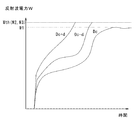
- FIG. 3 is a graph showing the change over time of the reflected wave power W when the cleaning process is executed with the inter-electrode distance D changed.
- the vertical axis of the graph represents the reflected wave power W
- the horizontal axis represents time.
- Three lines in the graph are obtained by changing only the distance D between the electrodes. That is, the three lines are the reference set value Dc, the upper set value Dc + d that is larger than the reference set value Dc by a predetermined amount, and the lower set value Dc ⁇ that is smaller than the reference set value Dc by a predetermined amount. It is a line at the time of d.
- d represents a constant.
- the predetermined amount of the upper set value Dc + d and the predetermined amount of the lower set value Dc ⁇ d are the same value (constant d), but the predetermined amount of the upper set value and the lower set value are different.
- the value may be different from the fixed amount.
- the reflected wave power W increases with time.
- the cleaning process is terminated when the reflected wave power W reaches a predetermined threshold value Wth.
- This threshold value Wth is a value of the reflected wave power W at which arc discharge starts to occur. That is, when the reflected wave power W is equal to or greater than the threshold value Wth, arc discharge occurs.
- two of the three lines have reached the threshold value Wth, and the cleaning process has been completed halfway, and one has not reached the threshold value Wth, and the cleaning process has been completed.
- the maximum value of the reflected wave power W that changes with time is preferably smaller.
- the maximum value of the reflected wave power W measured when the setting items in this embodiment, the interelectrode distance D and the cleaning gas flow rate V
- the first measured value the maximum value of the reflected wave power W measured when the setting item is set to the upper set value and the cleaning process is executed
- the second measured value the maximum value of the reflected wave power W measured when the setting item is set to the upper set value and the cleaning process is executed.
- Is set to the lower set value, and the maximum value of the reflected wave power W measured when the cleaning process is executed is referred to as a third measured value.
- the first measured value W1 which is the maximum value of the reflected wave power W when the interelectrode distance D is set to the reference set value Dc, and the reflection when the interelectrode distance D is set to the upper set value Dc + d.
- the first measured value W1 is the smallest. Accordingly, among the reference set value Dc, the upper set value Dc + d, and the lower set value Dc ⁇ d, the most preferable interelectrode distance D is the reference set value Dc.
- FIG. 4 is a graph showing the change over time of the reflected wave power W when the cleaning process is executed while changing the flow rate V of the cleaning gas.
- the vertical axis of the graph represents the reflected wave power W
- the horizontal axis represents time.
- Three lines in the graph are obtained by changing only the flow rate V of the cleaning gas. That is, the three lines indicate that the cleaning gas flow rate V is a reference set value Vc, an upper set value Vc + v that is larger than the reference set value Vc by a predetermined amount, and a lower set value Vc ⁇ that is smaller than the reference set value Vc by a predetermined amount.
- v represents a constant.
- the predetermined amount of the upper set value Vc + v and the predetermined amount of the lower set value Vc ⁇ v are the same value (constant v), but the predetermined amount of the upper set value and the lower set value are different.
- the value may be different from the fixed amount.
- the maximum value of the reflected wave power W that changes with time is small.
- the first measured value W1 that is the maximum value of the reflected wave power W when the cleaning gas flow rate V is set to the reference set value Vc, and the cleaning gas flow rate V is set to the upper set value Vc + v.
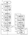
- FIG. 5 is a flowchart showing a control method of the plasma CVD apparatus 1.
- the two parameters D and V are appropriately adjusted in the cleaning process as follows.
- N is an arbitrary natural number, and is preferably a number enough to form the aforementioned unnecessary film.
- the distance control unit 13b and the flow rate control unit 13c use, as initial values of two parameters in the cleaning process, a reference set value Dc that is the current interelectrode distance D and a reference set value that is the current flow rate V of the cleaning gas.
- Set Vc That is, the distance control unit 13b controls the distance adjustment unit 20 to adjust the interelectrode distance D to the reference set value Dc, and the flow rate control unit 13c controls the flow rate adjustment valve 21 to reference the cleaning gas flow rate V. Adjust to set value Vc.
- a cleaning process is executed by the cleaning execution unit 13a.
- the reflected wave power is measured by the power detector 16a, and the first measured value W1 that is the maximum value and the corresponding interelectrode distance Dc are stored in the storage unit 13d in the control device 13 (step S3).
- the distance control unit 13b changes the set value of the interelectrode distance D to the upper set value Dc + d. That is, the distance control unit 13b controls the distance adjustment unit 20 to adjust the interelectrode distance D to the upper set value Dc + d. Thereafter, a cleaning process is executed by the cleaning execution unit 13a. At this time, the reflected wave power is measured by the power detector 16a, and the second measured value W2 that is the maximum value and the upper set value Dc + d that is the corresponding inter-electrode distance D are stored in the storage unit 13d in the control device 13. (Step S5).
- the distance control unit 13b changes the set value of the interelectrode distance D to the lower set value Dc-d. That is, the distance control unit 13b controls the distance adjustment unit 20 to adjust the interelectrode distance D to the lower set value Dc-d. Thereafter, a cleaning process is executed by the cleaning execution unit 13a. At this time, the reflected wave power is measured by the power detector 16a, and the third measured value W3 that is the maximum value and the lower set value Dc-d that is the corresponding inter-electrode distance are stored in the storage unit 13d in the control device 13. Stored (step S7).
- the distance control unit 13b specifies the smallest one among the first measurement value W1, the second measurement value W2, and the third measurement value W3 stored in the storage unit 13d (step S8).
- the first measurement value W1 is the smallest in step S8 (step S8: Y)
- the reference setting that is the current interelectrode distance D is set.
- the value Dc is maintained, and the adjustment of the cleaning gas flow rate V by the flow rate control unit 13c is started (steps S9 to S14).
- the distance control unit 13b updates the reference set value Dc of the interelectrode distance D (step S15). Specifically, when the second measurement value W2 is the minimum, the distance control unit 13b has the minimum third measurement value W3 so that the upper set value Dc + d becomes the current reference set value Dc. Updates the reference set value Dc of the inter-electrode distance D so that the lower set value Dc-d becomes the current reference set value Dc. Further, the upper set value Dc + d and the lower set value Dc-d of the inter-electrode distance D are also updated based on the updated reference set value Dc. Then, the control apparatus 13 advances a process to step S2.
- the film forming unit 13e performs the film forming process N times (step S9), and then the flow rate control unit 13c changes the set value of the cleaning gas flow rate V to the upper set value Vc + v. To do. That is, the flow rate control unit 13c controls the flow rate adjustment valve 21 to adjust the flow rate V of the cleaning gas to the upper set value Vc + v. Thereafter, a cleaning process is executed by the cleaning execution unit 13a. At this time, the reflected wave power is measured by the power detector 16a, and the second measured value W4, which is the maximum value, is stored in the storage unit 13d in the control device 13 (step S10).
- the flow rate control unit 13c changes the set value of the cleaning gas flow rate V to the lower set value Vc-v. That is, the flow rate control unit 13c controls the flow rate adjustment valve 21 to adjust the flow rate V of the cleaning gas to the lower set value Vc-v.
- a cleaning process is executed by the cleaning execution unit 13a.
- the reflected wave power is measured by the power detector 16a, and the third measured value W5 that is the maximum value is stored in the storage unit 13d in the control device 13 (step S12).
- the flow rate control unit 13c specifies the smallest one among the first measurement value W1, the second measurement value W4, and the third measurement value W5 stored in the storage unit 13d (step S13).
- the control device 13 advances the process to step S2. That is, since the reflected wave power cannot be reduced even if the current cleaning gas flow rate V is changed, the reference set value Vc, which is the current cleaning gas flow rate V, is maintained.
- the flow rate control unit 13c updates the reference set value Vc of the cleaning gas flow rate V (step S14). Specifically, when the second measurement value W4 is the minimum, the flow rate control unit 13c determines that the third measurement value W5 is the minimum so that the upper set value Vc + v becomes the current reference set value Vc. Updates the reference set value Vc of the cleaning gas flow rate V so that the lower set value Vc-v becomes the current reference set value Vc. Further, the upper set value Vc + v and the lower set value Vc ⁇ v of the cleaning gas flow rate V are also updated based on the updated reference set value Vc. Then, the control apparatus 13 advances a process to step S2.
- the storage unit 13d does not store all of the reference set values Vc and Dc, the upper set values Vc + v and Dc + d, and the lower set values Vc ⁇ v and Dc ⁇ d.
- the set values Vc, Dc and the constants v, d are stored, and based on the reference set values Vc, Dc and the constants v, d, the upper set values Vc + v, Dc + d and the lower set values Vc-v, Dc-d. May be calculated.
- a predetermined setting item (in this embodiment, based on the maximum value of the reflected wave power) Since the set values of the interelectrode distance D and the cleaning gas flow rate V) are changed, the occurrence of arc discharge can be suppressed. Specifically, since there is generally a correlation between the maximum value of the reflected wave power and the arc discharge, the setting value of the predetermined setting item is set based on the maximum value of the reflected wave power by the distance control unit 13b and the flow rate control unit 13c. By determining, the condition of the cleaning process can be changed so as to suppress the occurrence of arc discharge.
- the number of setting items is two, that is, the interelectrode distance D and the cleaning gas flow rate V. However, the number of setting items is not limited to this, and may be one or three or more. Also good.
- the first measured value W1 that is the maximum value of the reflected wave power when the reference set values Dc and Vc of the interelectrode distance and the cleaning gas flow rate that are the current set values are increased or decreased. Since it is confirmed whether it increases or decreases, it is possible to accurately grasp the relationship between the increase / decrease in the set value and the increase / decrease in the maximum value of the reflected wave power. This makes it possible to search for suitable conditions for the cleaning process with a smaller number of trials than in the past, that is, in a short time.
- the plasma CVD apparatus 1 is excellent in terms of time efficiency. .
- the setting value (reference setting value, upper setting value, or lower setting value) when taking the minimum value among the maximum values (first to third measurement values) of the reflected wave power is set. Maintain or update reference setpoints.
- the arc discharge tends to occur as the maximum value of the reflected wave power increases, it is preferable to reduce the maximum value of the reflected wave power in order to suppress the arc discharge. Therefore, the occurrence of arc discharge can be suppressed by adopting the setting value that minimizes the maximum value of the reflected wave power as the reference setting value as in the above configuration.
- a suitable condition for the cleaning process (that is, a combination of appropriate setting values for each setting item, hereinafter also referred to as a suitable condition) changes with time due to changes in various environmental elements (curvature of the upper electrode 14a, etc.).
- a suitable condition for the cleaning process that is, a combination of appropriate setting values for each setting item, hereinafter also referred to as a suitable condition
- the cleaning process is always performed with the upper set value and the lower set value as well as the reference set value, which is the current set value, even after the favorable conditions are once determined, and the first measurement is performed. It is checked whether there is a magnitude reversal between the value and the second and third measured values.
- the reference set value is the upper set value corresponding to the second measurement value that is smaller than the first measurement value, or The lower set value corresponding to the third measurement value that is smaller than the first measurement value is updated.
- a plurality of setting items (in this embodiment, two setting items of the interelectrode distance D and the cleaning gas flow rate V) are provided to improve the degree of freedom of the cleaning conditions. Also, by assigning priorities to the setting items, it is possible to search for suitable conditions for the cleaning process with a small number of trials, that is, in a short time, without acquiring data for all of the plurality of setting items. Here, it is preferable that the priority of the plurality of setting items is set higher as the setting item has a greater influence on the maximum value of the reflected wave power.
- the maximum value of the reflected wave power can be adjusted by adjusting the inter-electrode distance D and the flow rate V of the cleaning gas in the cleaning process, the occurrence of arc discharge can be suppressed.
- the reflected wave power tends to decrease as the inter-electrode distance D decreases, and the reflected wave power tends to decrease as the cleaning gas flow rate V decreases.
- the inter-electrode distance D and the cleaning gas flow rate V are not independent of each other in terms of increase / decrease in the reflected wave power, and the above-mentioned tendency may change if both of these parameters are changed.
- the present embodiment preferentially adjusts the inter-electrode distance D, which has a greater influence on the maximum value of the reflected wave power, and then adjusts the flow rate V of the cleaning gas. Even when the value is changed, the occurrence of arc discharge can be reliably suppressed in a short time.
- the pair of electrodes 14 are aluminum electrodes and are not anodized.
- arcing is likely to occur when using exposed aluminum electrodes that are not anodized. Therefore, it is preferable to anodize the electrode in order to prevent arc discharge.
- the rigidity of the upper electrode 14 a can be indirectly improved, so that the reliability of the plasma CVD apparatus 1 can be improved.
- the unsupported portion may be bent by its own weight over time.
- the parameter condition for reducing the reflected wave power also changes with time.
- arc discharge can be suppressed by using the plasma CVD apparatus 1 that appropriately adjusts appropriate parameters.
- the distance between the electrodes is adjusted with priority.
- the adjustment is not limited to this, and for example, the flow rate of the cleaning gas is prioritized. You may adjust and you may adjust two in parallel.
- a CVD apparatus includes a chamber, a pair of electrodes disposed vertically opposite to each other in the chamber, a gas supply source that supplies a source gas or a cleaning gas into the chamber, A high-frequency power source that supplies high-frequency power to at least one of the pair of electrodes, a measurement unit that measures reflected wave power of the high-frequency power supplied by the high-frequency power source, and a substrate placed on one of the pair of electrodes
- the source gas is supplied to the gas supply source and the high-frequency power is supplied to the high-frequency power source to generate plasma in the chamber to execute a film forming process for forming a thin film on the substrate.
- the cleaning gas is supplied to the gas supply source and the high frequency power source is
- a cleaning execution unit that supplies a frequency power to generate plasma in the chamber and removes an unnecessary film in the chamber, and a setting value of a predetermined setting item in the cleaning process is set a plurality of times in the past.
- a set value determining unit that determines based on a plurality of maximum values of the reflected wave power measured by changing the set value in the cleaning process.
- a predetermined setting item (between the electrodes in the present embodiment) is based on the maximum value of the reflected wave power. Since the set values of the distance and the flow rate of the cleaning gas are changed, the occurrence of arc discharge can be suppressed. Specifically, since there is generally a correlation between the maximum value of reflected wave power and arc discharge, the setting value determining unit determines the setting value of a predetermined setting item based on the maximum value of reflected wave power, thereby The cleaning process conditions can be changed to suppress the occurrence of discharge.
- the cleaning execution unit includes a current reference setting value of the setting item, an upper setting value that is larger than the reference setting value by a predetermined amount, and a lower setting that is smaller than the reference setting value by a predetermined amount.
- the set value is set to each of the values to execute the cleaning process, and the set value determination unit measures the reflection measured when the set value is set to the reference set value and the cleaning process is executed.
- a first measurement value that is the maximum value of wave power
- a second measurement value that is the maximum value of the reflected wave power measured when the cleaning process is executed with the set value set to the upper set value.
- the reference set value, the upper side based on the third measured value that is the maximum value of the reflected wave power measured when the set value is set to the lower set value and the cleaning process is executed.
- Value, and the lower set value may be updated or maintained.
- the cleaning process is not frequently performed from the viewpoint of production efficiency, and the film forming process is performed a plurality of times to the extent that an unnecessary film is generated before the cleaning process is performed. In addition, it takes a lot of time for one attempt to execute the cleaning process and measure the reflected wave power at the set value.
- the CVD apparatus is excellent in terms of time efficiency because the relationship between the increase / decrease in the set value and the increase / decrease in the maximum value of the reflected wave power can be accurately grasped with a small number of trials, that is, with a small amount of data. ing.
- the set value determination unit determines the reference set value, the upper side When the set value and the lower set value are maintained, and the second measured value is the smallest among the first measured value, the second measured value, and the third measured value
- the reference set value is Updating to the upper set value and updating the upper set value and the lower set value based on the updated reference set value, the first measured value, the second measured value, and the third measured value
- the reference set value is updated to the lower set value, and the upper set value and the lower set value are updated based on the updated reference set value. May be.
- the reference set value is set to the set value (reference set value, upper set value, or lower set value) when taking the minimum value among the maximum values (first to third measured values) of the reflected wave power. Maintain or update.
- arc discharge tends to occur as the maximum value of reflected wave power increases. Therefore, it is preferable to reduce the maximum value of reflected wave power in order to suppress arc discharge. Therefore, the occurrence of arc discharge can be suppressed by adopting the setting value that minimizes the maximum value of the reflected wave power as the reference setting value as in the above configuration.
- suitable conditions for the cleaning process change with time due to changes in various environmental factors.
- the cleaning process is always performed with the upper set value and the lower set value as well as the reference set value, which is the current set value, even after the favorable conditions are once determined, and the first measurement is performed. It is checked whether there is a magnitude reversal between the value and the second and third measured values.
- the reference set value is the upper set value corresponding to the second measurement value that is smaller than the first measurement value, or The lower set value corresponding to the third measurement value that is smaller than the first measurement value is updated.
- the setting value determination unit determines the reference setting value, the upper setting value, and the lower side for the setting item having the highest priority among the plurality of setting items.
- a process of updating or maintaining a setting value is performed, and when the reference setting value, the upper setting value, and the lower setting value are maintained for the setting item having the highest priority, For the higher setting items, processing for updating or maintaining the reference set value, the upper set value, and the lower set value may be performed.
- a plurality of setting items are provided to improve the freedom of cleaning conditions. Also, by assigning priorities to the setting items, it is possible to search for suitable conditions for the cleaning process with a small number of trials, that is, in a short time, without acquiring data for all of the plurality of setting items.
- the priority of the plurality of setting items is set higher as the setting item has a greater influence on the maximum value of the reflected wave power.
- the setting item may further include a distance adjusting unit that includes an inter-electrode distance of the pair of electrodes and adjusts the inter-electrode distance to a setting value designated by the setting value determining unit.
- the set value determining unit controls the distance adjusting unit to adjust the inter-electrode distance to an appropriate value, so that arc discharge can be efficiently suppressed.
- the setting item includes a flow rate of the cleaning gas supplied into the chamber from the gas supply source, and adjusts the flow rate of the cleaning gas to a set value designated by the set value determining unit. You may further provide a flow volume adjustment part.
- the set value determining unit controls the flow rate adjusting unit to adjust the flow rate of the cleaning gas to an appropriate value, so that arc discharge can be efficiently suppressed.
- the setting item further includes a distance adjusting unit that includes an inter-electrode distance of the pair of electrodes, and adjusts the inter-electrode distance to a setting value specified by the setting value determining unit, Includes a flow rate of the cleaning gas supplied from the gas supply source into the chamber, and further includes a flow rate adjusting unit that adjusts the flow rate of the cleaning gas to a set value specified by the set value determining unit,
- the inter-electrode distance between the pair of electrodes may be a setting item with the highest priority
- the flow rate of the cleaning gas may be a setting item with the second highest priority.
- the maximum value of the reflected wave power can be adjusted by adjusting the distance between the electrodes and the flow rate of the cleaning gas in the cleaning process, the occurrence of arc discharge can be suppressed.
- the reflected wave power tends to decrease as the distance between the electrodes decreases, and the reflected wave power tends to decrease as the flow rate of the cleaning gas decreases.
- the distance between the electrodes and the flow rate of the cleaning gas are not related to each other, and the above-mentioned tendency may be changed when these parameters are changed together.
- the distance between the electrodes that has a greater influence on the maximum value of the reflected wave power is preferentially adjusted, and then the cleaning gas flow rate is adjusted, so the two settings are changed. Even in this case, the occurrence of arc discharge can be reliably suppressed in a short time.
- the pair of electrodes are aluminum electrodes, and are not anodized, and the electrodes themselves may be exposed.
- the aluminum electrode is not anodized.
- arcing is likely to occur when using exposed aluminum electrodes that are not anodized. Therefore, it is preferable to anodize the electrode in order to prevent arc discharge.
- the CVD apparatus may further include a reinforcing plate that supports the electrode disposed on the upper side of the pair of electrodes from the upper side at least at one point instead of the entire surface.
- the rigidity of the electrode can be indirectly improved by providing the reinforcing plate, the reliability of the CVD apparatus can be improved.
- the electrode when the electrode is supported by a point rather than the entire surface of the reinforcing plate, the unsupported portion may be bent by its own weight over time.
- the parameter condition for reducing the reflected wave power also changes with time.
- arc discharge can be suppressed by using a CVD apparatus that appropriately adjusts appropriate parameters.
- the CVD apparatus may further include a matching circuit that is electrically connected between one of the pair of electrodes and the high-frequency power source and includes the measurement unit.
- the impedance of the pair of electrodes can be matched by the matching circuit, the reflected wave power can be reduced. Therefore, arc discharge can be further suppressed.
- a cleaning method includes a chamber, a pair of electrodes disposed vertically opposite to each other in the chamber, a gas supply source that supplies a source gas or a cleaning gas into the chamber,
- a cleaning method for a CVD apparatus comprising: a high-frequency power source that supplies high-frequency power to at least one of the pair of electrodes; and a measurement unit that measures reflected wave power of the high-frequency power supplied by the high-frequency power source.
- the source gas is supplied with the substrate placed on one of the electrodes, and the high-frequency power is supplied to generate plasma in the chamber to form a thin film on the substrate a predetermined number of times. Each time, the cleaning gas is supplied and the high-frequency power is supplied to generate plasma in the chamber.
- a plurality of reflected wave powers measured by changing a set value of a predetermined setting item in the cleaning process in the past multiple times of the cleaning process. And determining based on the maximum value of.
- Plasma CVD equipment (CVD equipment) 2 Substrate 10 Chamber 10a Chamber body 10b Lid 11 Gas supply source 12 Exhaust mechanism 13 Control device 13a Cleaning execution unit 13b Distance control unit (set value determination unit) 13c Flow rate control unit (set value determination unit) 13d Storage unit 13e Deposition execution unit 14 Pair of electrodes 14a Upper electrode 14b Lower electrode 15 Backing plate (reinforcing plate) 16 Matching circuit 16a Power detector (measurement unit) 17 High Frequency Power Supply 18 Dielectric 19 Lifting Rod 20 Distance Adjustment Unit 21 Flow Control Valve (Flow Control Unit)
Landscapes
- Chemical & Material Sciences (AREA)
- Engineering & Computer Science (AREA)
- Physics & Mathematics (AREA)
- Plasma & Fusion (AREA)
- Analytical Chemistry (AREA)
- General Chemical & Material Sciences (AREA)
- Chemical Kinetics & Catalysis (AREA)
- Materials Engineering (AREA)
- Mechanical Engineering (AREA)
- Metallurgy (AREA)
- Organic Chemistry (AREA)
- Epidemiology (AREA)
- Public Health (AREA)
- Health & Medical Sciences (AREA)
- Plasma Technology (AREA)
- Chemical Vapour Deposition (AREA)
Abstract
CVD装置1は、チャンバ10と、一対の電極14と、ガス供給源11と、高周波電源17と、反射波電力を測定する電力検出器16aと、一対の電極14の一方に基板2が載置された状態で、ガス供給源11に原料ガスを供給させるとともに高周波電源17に高周波電力を供給させてチャンバ10内にプラズマを発生させ、基板2上に薄膜を形成する成膜処理を実行する成膜実行部13eと、成膜処理を所定回数実行するごとに、ガス供給源11にクリーニングガスを供給させるとともに高周波電源17に高周波電力を供給させてチャンバ10内にプラズマを発生させ、チャンバ10内の不要膜を除去するクリーニング処理を実行するクリーニング実行部13aと、クリーニング処理における所定の設定項目の設定値を、過去複数回のクリーニング処理において設定値を変えて測定された複数の反射波電力の最大値に基づいて決定する設定値決定部13b,13cとを備える。
Description
本発明は、CVD(chemical vapor deposition)装置およびそのクリーニング方法に関する。
化学的な成膜によって基板上に薄膜を形成するための装置として、CVD装置が知られている。このようなCVD装置の一例として、プラズマを利用したプラズマCVD装置がある。プラズマCVD装置は、チャンバ内において、電極間に高周波電圧を印加し、プラズマを生成し、プラズマによってチャンバ内に充填されたガスを活性化し、活性化されたガスを基板に到達させ、基板上に薄膜を形成する装置である。
プラズマCVD装置では、成膜処理が複数回行われると、基板上だけでなく、電極およびチャンバの内壁等にも薄膜(不要膜)が形成される。これらの不要膜を除去するためには、定期的にクリーニング処理を実行する必要がある。例えば、特許文献1には、薄膜を形成する原料ガスとは異なる、不要膜を除去するためのクリーニングガスをチャンバ内に導入し、プラズマを生成し、プラズマによってクリーニングガスを活性化させ、活性化させたクリーニングガスによって不要膜を除去するクリーニング方法が開示されている。
特許文献1に開示されたクリーニング方法において、プラズマを生成するために電極間に高周波電圧を印加すると、その反射波電力が観測される。所定以上の反射波電力が観測されると、チャンバ内でアーク放電が発生するおそれがある。アーク放電が発生すると、チャンバ内の部材が損傷し、チャンバ内にパーティクルが飛散する。パーティクルは製造に悪影響を及ぼし、製造の歩溜まりが低下するおそれがある。
本発明は、アーク放電の発生を抑制できるCVD装置およびそのクリーニング方法を提供することを目的とする。
本発明のCVD装置は、チャンバと、前記チャンバ内に上下に対向して配置される一対の電極と、前記チャンバ内に原料ガスまたはクリーニングガスを供給するガス供給源と、前記一対の電極の少なくとも一方に高周波電力を供給する高周波電源と、前記高周波電源により供給された高周波電力の反射波電力を測定する測定部と、前記一対の電極の一方に基板が載置された状態で、前記ガス供給源に前記原料ガスを供給させるとともに前記高周波電源に前記高周波電力を供給させて前記チャンバ内にプラズマを発生させ、前記基板上に薄膜を形成する成膜処理を実行する成膜実行部と、前記成膜処理を所定回数実行するごとに、前記ガス供給源に前記クリーニングガスを供給させるとともに前記高周波電源に前記高周波電力を供給させて前記チャンバ内にプラズマを発生させ、前記チャンバ内の不要膜を除去するクリーニング処理を実行するクリーニング実行部と、前記クリーニング処理における所定の設定項目の設定値を、過去複数回の前記クリーニング処理において前記設定値を変えて測定された複数の前記反射波電力の最大値に基づいて決定する設定値決定部とを備える。
本発明のクリーニング方法は、チャンバと、前記チャンバ内に上下に対向して配置される一対の電極と、前記チャンバ内に原料ガスまたはクリーニングガスを供給するガス供給源と、前記一対の電極の少なくとも一方に高周波電力を供給する高周波電源と、前記高周波電源により供給された高周波電力の反射波電力を測定する測定部とを備えるCVD装置のクリーニング方法であって、前記一対の電極の一方に基板が載置された状態で前記原料ガスを供給するとともに前記高周波電力を供給して前記チャンバ内にプラズマを発生させ前記基板上に薄膜を形成する成膜処理を所定回数実行するごとに、前記クリーニングガスを供給するとともに前記高周波電力を供給して前記チャンバ内にプラズマを発生させ前記チャンバ内の不要膜を除去するクリーニング処理を実行し、前記クリーニング処理における所定の設定項目の設定値を、過去複数回の前記クリーニング処理において前記設定値を変えて測定された複数の前記反射波電力の最大値に基づいて決定することを含む。
本発明によれば、CVD装置およびそのクリーニング方法において、クリーニング処理における所定の設定項目の設定値を、反射波電力の最大値に基づいて決定することで、アーク放電の発生を抑制できる。
以下、添付図面を参照して本発明の実施形態を説明する。
図1は、一実施形態に係るプラズマCVD装置1(CVD装置の一例)の模式的な部分断面図である。プラズマCVD装置1は、基板2上に薄膜を形成するものであり、例えば、大型ディスプレイの液晶セル基板を製造する際に使用される。本実施形態のプラズマCVD装置1は、大型ディスプレイの液晶セル基板2をプラズマ処理し、基板2上に薄膜を形成するものである。プラズマCVD装置1は、平面視矩形状の基板2を収容するチャンバ10と、チャンバ10内に原料ガスまたはクリーニングガスを供給するガス供給源11と、チャンバ10内の気体を排気する排気機構12と、制御装置13とを少なくとも備えている。基板2のサイズは、例えば2880mm×3130mmである。
チャンバ10は、開口部を有するチャンバ本体10aと、その開口部を開閉する蓋体10bとから構成される。チャンバ本体10aおよび蓋体10bは、それぞれ接地されており、それぞれ有底の四角筒形状である。チャンバ本体10aおよび蓋体10bは、例えばアルミニウムなどの金属製である。
また、チャンバ10内には、平板状の上部電極14aおよび下部電極14bが平行に上下に配置され、これらによって一対の電極14が構成されている。一対の電極14は、例えばアルミニウム電極である。特に本実施形態のように、大型ディスプレイを製造する際に使用されるプラズマCVD装置1では、液晶セル基板2が大型であるため、一対の電極14は、アノダイズ処理されておらず、電極自体が露出している。
上部電極14aは、補強板として金属製のバッキングプレート15に支持され、下部電極14bに対向して配置されている。ガス供給源11から供給される原料ガスまたはクリーニングガスは、バッキングプレート15と上部電極14aとの間の拡散空間で拡散した後、上部電極14aに設けられた複数の吐出口からチャンバ10内に供給される。また、上部電極14aは、マッチング回路16と、マッチング回路16に接続された高周波電源17とを介して接地されている。また、上部電極14aおよびバッキングプレート15と、チャンバ10との間には、セラミックス等からなる誘電体18が充填されている。
下部電極14bは、上部電極14aに対向して配置されている。下部電極14bも基板2と同様に平面視矩形状である。より詳しくは、基板2の下面の全部を下部電極14bで支持するため、下部電極14bの平面視形状は基板2の平面視形状よりも大きい。下部電極14bの上面は、基板2が載置される載置面となっている。下部電極14bは、昇降ロッド19によって下方から支持されている。昇降ロッド19は、昇降可能であり、図1に概念的に示される距離調整部20によって昇降される。距離調整部20は、例えばモータおよびギヤなどからなる周知の昇降機構であり得る。従って、下部電極14bを昇降ロッド19によって昇降させることで、一対の電極14の電極間距離Dを変更可能である。また、下部電極14bは、接地されており、マッチング回路16にも電気的に接続されている。
マッチング回路16は、上部電極14aおよび下部電極14bのいずれか一方(本実施形態では、上部電極14a)と電気的に接続されており、上部電極14aおよび下部電極14bのインピーダンスを整合させるために設けられている。そのため、マッチング回路16には、高周波電源17を用いる装置に一般に使用される公知の整合器が含まれている。また、マッチング回路16には、高周波電源17から一対の電極14に供給する電力の成分である進行波電力および反射波電力を測定するための電力検出器16a(測定部の一例)が含まれている。この進行波電力からこの反射波電力を差し引いたものが、高周波電源17から一対の電極14に供給される実際上の電力となる。従って、反射波電力は極力小さい方が好ましい。
ガス供給源11は、原料ガスまたはクリーニングガスをチャンバ10内に供給するために設けられており、流量調整弁21を介してチャンバ10と流体的に接続されている。ここで、流量調整弁21は流量調整部の一例である。原料ガスは、後述する成膜処理において、基板上に形成する薄膜の原料となるガスであり、薄膜の種類に応じて適宜選択される。クリーニングガスは、後述するクリーニング処理において、意図せず基板2上以外に形成された不要膜を除去するためのガスであり、不要膜の種類に応じて適宜選択される。
排気機構12は、チャンバ10内の真空度を所定値にするために設けられており、排気管、真空ポンプ、および圧力調整バルブなどから構成される。
このようなプラズマCVD装置1を用いて基板2上に薄膜を形成する場合、まず、図1の断面図では図示されない搬入出口からチャンバ10内に基板2を搬入して下部電極14b上に載置する。次いで、排気機構12によってチャンバ10内の気体を排気する。そして、ガス供給源11からチャンバ10内に原料ガスを導入するとともにチャンバ10内の圧力を調整する。この圧力調整後、高周波電源17から一対の電極14にマッチング回路16を介して高周波電圧を印加する。この高周波電圧によってチャンバ10内にプラズマを発生させ、このプラズマによって原料ガスを活性化し、活性化した原料ガスを基板2に到達させることで基板2上に薄膜を形成する。以降、このように薄膜を形成する処理を成膜処理という。このような成膜処理は、制御装置13によって制御されている。
このような成膜処理が複数回行われると、基板2上だけでなく、排気機構12の排気管、一対の電極14、およびチャンバ10の内壁等にも薄膜(不要膜)が形成される。このような不要膜の発生は、成膜処理の精度に悪影響を及ぼすため、不要膜は定期的に除去される必要がある。
このような不要膜を除去するために、成膜処理を所定回数行うごとにクリーニング処理が行われる。クリーニング処理では、基板2をチャンバ10内に搬入していない状態で、上記の成膜処理の原料ガスをクリーニングガスに変更してプラズマ処理が行われる。このクリーニング処理によって、活性化したクリーニングガスが上記不要膜を除去するため、成膜処理の精度を維持できる。このようなクリーニング処理は、制御装置13によって制御されている。
図2に示すように、制御装置13は、所定回数の成膜処理を行うごとにクリーニング処理を実行するクリーニング実行部13aと、クリーニング処理における反射波電力の最大値を減少させるように距離調整部20および流量調整弁21を制御する距離制御部13b(設定値決定部の一例)および流量制御部13c(設定値決定部の一例)と、後述する設定値およびマッチング回路16内の電力検出器16aにて測定された反射波電力の最大値を記憶する記憶部13dと、成膜処理を実行する成膜実行部13eとを有する。距離制御部13bは、距離調整部20を制御して電極間距離Dを調整する。流量制御部13cは、流量調整弁21を制御してクリーニングガスの流量Vを調整する。本実施形態では、制御装置13は、クリーニング処理の際、これらの二つのパラメータD,Vをクリーニング処理における設定項目(以下単に、設定項目ともいう)として変更し得る。クリーニング処理においてこれらの二つのパラメータD,Vが適正な値に調整されていないと、マッチング回路16内の電力検出器16aで測定される反射波電力が増大する。所定以上の反射波電力が発生すると、製造に悪影響を及ぼすアーク放電が発生する。本実施形態に係るプラズマCVD装置1は、制御装置13の距離制御部13bおよび流量制御部13cによって、二つのパラメータD,Vを設定項目として適正に調整することで、反射波電力を減少させ、アーク放電を抑制する。特に、一対の電極14の電極間距離Dは、反射波電力の最大値に与える影響が大きいため、設定項目として有効である。従って、距離制御部13bが距離調整部20を制御して電極間距離Dを適正な値に調整することで、効率的にアーク放電を抑制し得る。同様に、クリーニングガスの流量Vは、反射波電力の最大値に与える影響が大きいため、設定項目として有効である。従って、流量制御部13cが流量調整弁21を制御してクリーニングガスの流量Vを適正な値に調整することで、効率的にアーク放電を抑制し得る。
図3は、電極間距離Dを変えてクリーニング処理を実行した場合における反射波電力Wの時間変化を示すグラフである。グラフの縦軸は、反射波電力Wを表し、横軸は時間を表している。グラフ中の三つのラインは、電極間距離Dのみを変えたものである。即ち、三つのラインは、電極間距離Dが、それぞれ基準設定値Dc,基準設定値Dcよりも所定量だけ大きい上側設定値Dc+d,基準設定値Dcよりも所定量だけ小さい下側設定値Dc-dのときのラインである。ここで、dは定数を表す。なお、本実施形態において、上側設定値Dc+dの所定量と下側設定値Dc-dの所定量とは同じ値(定数d)であるが、上側設定値の所定量と下側設定値の所定量とが異なる値であってもよい。
グラフに示すように、反射波電力Wは、時間の経過とともに増加する。本実施形態のプラズマCVD装置1では、反射波電力Wが所定の閾値Wthに到達した場合に、クリーニング処理を終了するようになっている。この閾値Wthは、アーク放電が発生し始める反射波電力Wの値である。即ち、反射波電力Wが閾値Wth以上となると、アーク放電が発生する。図3のグラフでは、三つのラインのうち、二つが閾値Wthに到達し、途中でクリーニング処理を終了しており、一つが閾値Wthに到達しておらず、クリーニング処理を完了している。
アーク放電を抑制する観点では、時間変化する反射波電力Wの最大値は、小さい方が好ましい。以下、設定項目(本実施形態では、電極間距離D及びクリーニングガスの流量V)の設定値を基準設定値に設定してクリーニング処理を実行した場合に測定された反射波電力Wの最大値を第1測定値といい、設定項目の設定値を上側設定値に設定してクリーニング処理を実行した場合に測定された反射波電力Wの最大値を第2測定値といい、設定項目の設定値を下側設定値に設定してクリーニング処理を実行した場合に測定された反射波電力Wの最大値を第3測定値という。図示の例では、電極間距離Dを基準設定値Dcに設定した場合の反射波電力Wの最大値である第1測定値W1と、電極間距離Dを上側設定値Dc+dに設定した場合の反射波電力Wの最大値である第2測定値W2と、電極間距離Dを下側設定値Dc-dに設定した場合の反射波電力Wの最大値である第3測定値W3とのうち、第1測定値W1が最も小さい。従って、基準設定値Dc、上側設定値Dc+d、および下側設定値Dc-dの中で、最も好ましい電極間距離Dは、基準設定値Dcである。
図4は、クリーニングガスの流量Vを変えてクリーニング処理を実行した場合における反射波電力Wの時間変化を示すグラフである。グラフの縦軸は、反射波電力Wを表し、横軸は時間を表している。グラフ中の三つのラインは、クリーニングガスの流量Vのみを変えたものである。即ち、三つのラインは、クリーニングガス流量Vが、それぞれ基準設定値Vc,基準設定値Vcよりも所定量だけ大きい上側設定値Vc+v,基準設定値Vcよりも所定量だけ小さい下側設定値Vc-vのときのラインである。ここで、vは定数を表す。なお、本実施形態において、上側設定値Vc+vの所定量と下側設定値Vc-vの所定量とは同じ値(定数v)であるが、上側設定値の所定量と下側設定値の所定量とが異なる値であってもよい。
図4のグラフでは、三つのラインのうち、いずれも閾値Wthを超えておらず、全て処理を完了している。前述のように、アーク放電を抑制する観点では、時間変化する反射波電力Wの最大値は、小さい方が好ましい。図示の例では、クリーニングガスの流量Vを基準設定値Vcに設定した場合の反射波電力Wの最大値である第1測定値W1と、クリーニングガスの流量Vを上側設定値Vc+vに設定した場合の反射波電力Wの最大値である第2測定値W2と、クリーニングガスの流量Vを下側設定値Vc-vに設定した場合の反射波電力Wの最大値である第3測定値W3とのうち、第2測定値W2が最も小さい。従って、基準設定値Vc、上側設定値Vc+v、および下側設定値Vc-vの中で、最も好ましいクリーニングガスの流量Vは、上側設定値Vc+vである。
図5は、プラズマCVD装置1の制御方法を示すフローチャートである。本実施形態では、このフローチャートに従って、クリーニング処理において、以下のように上記二つのパラメータD,Vを適正に調整している。
制御が開始される(ステップS1)と、まず、成膜実行部13eが成膜処理をN回実行する(ステップS2)。ここで、Nは任意の自然数であり、好ましくは前述の不要膜が形成される程度の数である。
次に、距離制御部13bおよび流量制御部13cが、クリーニング処理における二つのパラメータの初期値として、現在の電極間距離Dである基準設定値Dcおよび現在のクリーニングガスの流量Vである基準設定値Vcを設定する。すなわち、距離制御部13bが、距離調整部20を制御して電極間距離Dを基準設定値Dcに調整し、流量制御部13cが、流量調整弁21を制御してクリーニングガスの流量Vを基準設定値Vcに調整する。その後、クリーニング実行部13aによってクリーニング処理が実行される。このとき、電力検出器16aによって反射波電力が測定され、その最大値である第1測定値W1および対応する電極間距離Dcが制御装置13内の記憶部13dに記憶される(ステップS3)。
次に、成膜実行部13eが再び成膜処理をN回実行した(ステップS4)後、距離制御部13bが、電極間距離Dの設定値を上側設定値Dc+dに変更する。すなわち、距離制御部13bが、距離調整部20を制御して電極間距離Dを上側設定値Dc+dに調整する。その後、クリーニング実行部13aによってクリーニング処理が実行される。このとき、電力検出器16aによって反射波電力が測定され、その最大値である第2測定値W2および対応する電極間距離Dである上側設定値Dc+dが制御装置13内の記憶部13dに記憶される(ステップS5)。
それからさらに成膜実行部13eが成膜処理をN回実行した(ステップS6)後、距離制御部13bが、電極間距離Dの設定値を下側設定値Dc-dに変更する。すなわち、距離制御部13bが、距離調整部20を制御して電極間距離Dを下側設定値Dc-dに調整する。その後、クリーニング実行部13aによってクリーニング処理が実行される。このとき、電力検出器16aによって反射波電力が測定され、その最大値である第3測定値W3および対応する電極間距離である下側設定値Dc-dが制御装置13内の記憶部13dに記憶される(ステップS7)。
その後、距離制御部13bは、記憶部13dに記憶された第1測定値W1,第2測定値W2,および第3測定値W3の中から、最小のものを特定する(ステップS8)。ステップS8において第1測定値W1が最小であるとき(ステップS8:Y)、現在の電極間距離Dを変えても反射波電力の減少が見込めないため、現在の電極間距離Dである基準設定値Dcが維持され、流量制御部13cによるクリーニングガスの流量Vの調整が開始される(ステップS9~ステップS14)。
一方、ステップS8において第1測定値W1が最小でないとき(ステップS8:N)、距離制御部13bは、電極間距離Dの基準設定値Dcを更新する(ステップS15)。具体的には、距離制御部13bは、第2測定値W2が最小である場合は上側設定値Dc+dが新たに現在の基準設定値Dcとなるように、第3測定値W3が最小である場合は下側設定値Dc-dが新たに現在の基準設定値Dcとなるように、電極間距離Dの基準設定値Dcを更新する。また、更新後の基準設定値Dcに基づいて、電極間距離Dの上側設定値Dc+dおよび下側設定値Dc-dも更新される。その後、制御装置13は、処理をステップS2へ進める。
クリーニングガスの流量Vの調整では、成膜実行部13eが成膜処理をN回実行した(ステップS9)後、流量制御部13cが、クリーニングガスの流量Vの設定値を上側設定値Vc+vに変更する。すなわち、流量制御部13cが、流量調整弁21を制御してクリーニングガスの流量Vを上側設定値Vc+vに調整する。その後、クリーニング実行部13aによってクリーニング処理が実行される。このとき、電力検出器16aによって反射波電力が測定され、その最大値である第2測定値W4が制御装置13内の記憶部13dに記憶される(ステップS10)。
それからさらに成膜実行部13eが成膜処理をN回実行した(ステップS11)後、流量制御部13cが、クリーニングガスの流量Vの設定値を下側設定値Vc-vに変更する。すなわち、流量制御部13cが、流量調整弁21を制御してクリーニングガスの流量Vを下側設定値Vc-vに調整する。その後、クリーニング実行部13aによってクリーニング処理が実行される。このとき、電力検出器16aによって反射波電力が測定され、その最大値である第3測定値W5が制御装置13内の記憶部13dに記憶される(ステップS12)。
その後、流量制御部13cは、記憶部13dに記憶された第1測定値W1,第2測定値W4,および第3測定値W5の中から、最小のものを特定する(ステップS13)。ステップS13において第1測定値W1が最小であるとき(ステップS13:Y)、制御装置13は、処理をステップS2へ進める。すなわち、現在のクリーニングガスの流量Vを変えても反射波電力の減少が見込めないため、現在のクリーニングガスの流量Vである基準設定値Vcが維持される。
ステップS13において第1測定値W1が最小でないとき(ステップS13:N)、流量制御部13cは、クリーニングガスの流量Vの基準設定値Vcを更新する(ステップS14)。具体的には、流量制御部13cは、第2測定値W4が最小である場合は上側設定値Vc+vが新たに現在の基準設定値Vcとなるように、第3測定値W5が最小である場合は下側設定値Vc-vが新たに現在の基準設定値Vcとなるように、クリーニングガスの流量Vの基準設定値Vcを更新する。また、更新後の基準設定値Vcに基づいて、クリーニングガスの流量Vの上側設定値Vc+vおよび下側設定値Vc-vも更新される。その後、制御装置13は、処理をステップS2へ進める。
なお、本実施形態のように、記憶部13dに、基準設定値Vc,Dc、上側設定値Vc+v,Dc+d、及び下側設定値Vc-v,Dc-dの全てを記憶するのではなく、基準設定値Vc,Dcと定数v,dとを記憶しておき、基準設定値Vc,Dc及び定数v,dに基づいて、上側設定値Vc+v,Dc+d及び下側設定値Vc-v,Dc-dを算出してもよい。
本実施形態によれば、複数回の成膜処理によってチャンバ10内に形成された不要膜をクリーニング処理によって除去する際、反射波電力の最大値に基づいて所定の設定項目(本実施形態では、電極間距離Dおよびクリーニングガスの流量V)の設定値を変更しているため、アーク放電の発生を抑制できる。具体的には、一般に反射波電力の最大値とアーク放電には相関があるため、距離制御部13bおよび流量制御部13cによって反射波電力の最大値に基づいて上記所定の設定項目の設定値を決定することで、アーク放電の発生を抑制するようにクリーニング処理の条件を変更できる。なお、本実施形態において、設定項目の数は、電極間距離Dおよびクリーニングガスの流量Vの二つであるが、これに限られず、一つであってもよいし、三つ以上であってもよい。
また、本実施形態によれば、現在の設定値である電極間距離およびクリーニングガスの流量の基準設定値Dc,Vcを増減させた場合に反射波電力の最大値である第1測定値W1が増加または減少するかを確認しているため、設定値の増減と反射波電力の最大値の増減との関係を的確に把握できる。これにより、従来よりも少ない試行回数で、即ち短時間でクリーニング処理の好適な条件を探索できる。本実施形態では少ない試行回数で、即ち少ないデータ量で設定値の増減と反射波電力の最大値の増減との関係を的確に把握できるため、時間効率の観点でプラズマCVD装置1は優れている。
また、本実施形態によれば、反射波電力の最大値(第1~3測定値)のうち、最小値をとるときの設定値(基準設定値、上側設定値、または下側設定値)に基準設定値を維持または更新する。一般に、プラズマCVD装置1では、反射波電力の最大値が大きいほど、アーク放電が発生する傾向にあるため、アーク放電の抑制のためには反射波電力の最大値を小さくすることが好ましい。従って、上記構成のように、基準設定値として反射波電力の最大値を最も小さくする設定値を採用することによってアーク放電の発生を抑制できる。
また、クリーニング処理の好適な条件(すなわち、各設定項目の適切な設定値の組み合わせであり、以下、好適条件ともいう)は、種々の環境要素の変化(上部電極14aの湾曲等)によって経時変化する。上記構成によれば、一旦好適条件が決定された後でも、常に、現在の設定値である基準設定値だけでなく、上側設定値および下側設定値にてクリーニング処理が行われ、第1測定値と第2測定値および第3測定値との間で大小の逆転が生じていないかどうかが確認される。そして、第2測定値または第3測定値が第1測定値よりも小さくなった場合に、基準設定値が、第1測定値よりも小さくなった第2測定値に対応する上側設定値、または、第1測定値よりも小さくなった第3測定値に対応する下側設定値に更新される。これにより、好適条件が経時変化する中で、その経時変化に追従させて設定値を適切な値に維持できる。
また、本実施形態によれば、複数の設定項目(本実施形態では、電極間距離Dおよびクリーニングガスの流量Vの二つの設定項目)を設け、クリーニング条件の自由度を向上させている。また、設定項目に優先順位を付けることで複数の設定項目の全てについてデータを取得することなく、少ない試行回数で、即ち短時間でクリーニング処理の好適な条件を探索できる。ここで、複数の設定項目の優先順位は、反射波電力の最大値に与える影響の大きな設定項目ほど高く設定されていることが好ましい。
また、本実施形態によれば、クリーニング処理において、電極間距離Dおよびクリーニングガスの流量Vを調整することで反射波電力の最大値を調整できるため、アーク放電の発生を抑制し得る。プラズマCVD装置1では、電極間距離Dが狭いほど反射波電力は減少し、クリーニングガスの流量Vが少ないほど反射波電力は減少する傾向にある。しかし、反射波電力の増減に関して電極間距離Dとクリーニングガスの流量Vとは独立したパラメータの関係になく、これらのパラメータをともに変更すると、上記傾向が変わることがある。この知見に基づき、本実施形態では、反射波電力の最大値に与える影響がより大きな電極間距離Dを優先的に調整し、その後にクリーニングガスの流量Vを調整しているため、二つの設定値を変更した場合でも短時間で確実にアーク放電の発生を抑制できる。
また、本実施形態によれば、一対の電極14は、アルミニウム電極であり、アノダイズ処理されていない。一般に、アーク放電は、アノダイズ処理されていない露出したアルミニウム電極を使用するときに発生しやすい。そのため、アーク放電を防止するためには電極をアノダイズ処理することが好ましい。しかし、大型電極の場合のように電極をアノダイズ処理することが困難である場合もある。このようなアノダイズ処理されていないアルミニウム電極を使用する場合には、上記のようなアーク放電を抑制できるプラズマCVD装置1を使用することが有効である。
また、本実施形態によれば、バッキングプレート15を設けることで、上部電極14aの剛性を間接的に向上できるため、プラズマCVD装置1の信頼性を向上できる。しかし、バッキングプレート15の全面ではなく点で上部電極14aを支持するとき、支持されていない部分が時間の経過とともに自重によって湾曲することがある。このような経時変化を伴う電極を使用すると、反射波電力を減少させるためのパラメータ条件も経時変化する。これに対し、上記のように、適正なパラメータ調整を適宜行うプラズマCVD装置1を使用することで、アーク放電を抑制できる。
上記実施形態では、電極間距離と、クリーニングガスの流量とを調整する際、電極間距離を優先して調整しているが、調整はこれに限定されず、例えばクリーニングガスの流量を優先して調整してもよいし、二つを並列に調整してもよい。
本発明および実施形態をまとめると、次のようになる。
一実施形態において、本発明に係るCVD装置は、チャンバと、前記チャンバ内に上下に対向して配置される一対の電極と、前記チャンバ内に原料ガスまたはクリーニングガスを供給するガス供給源と、前記一対の電極の少なくとも一方に高周波電力を供給する高周波電源と、前記高周波電源により供給された高周波電力の反射波電力を測定する測定部と、前記一対の電極の一方に基板が載置された状態で、前記ガス供給源に前記原料ガスを供給させるとともに前記高周波電源に前記高周波電力を供給させて前記チャンバ内にプラズマを発生させ、前記基板上に薄膜を形成する成膜処理を実行する成膜実行部と、前記成膜処理を所定回数実行するごとに、前記ガス供給源に前記クリーニングガスを供給させるとともに前記高周波電源に前記高周波電力を供給させて前記チャンバ内にプラズマを発生させ、前記チャンバ内の不要膜を除去するクリーニング処理を実行するクリーニング実行部と、前記クリーニング処理における所定の設定項目の設定値を、過去複数回の前記クリーニング処理において前記設定値を変えて測定された複数の前記反射波電力の最大値に基づいて決定する設定値決定部とを備える。
この構成によれば、複数回の成膜処理によってチャンバ内に形成された不要膜をクリーニング処理によって除去する際、反射波電力の最大値に基づいて所定の設定項目(本実施形態では、電極間距離およびクリーニングガスの流量)の設定値を変更しているため、アーク放電の発生を抑制できる。具体的には、一般に反射波電力の最大値とアーク放電には相関があるため、設定値決定部によって反射波電力の最大値に基づいて所定の設定項目の設定値を決定することで、アーク放電の発生を抑制するようにクリーニング処理の条件を変更できる。
一つの局面において、前記クリーニング実行部は、前記設定項目の現在の基準設定値と、前記基準設定値よりも所定量だけ大きい上側設定値と、前記基準設定値よりも所定量だけ小さい下側設定値とにそれぞれ前記設定値を設定して前記クリーニング処理を実行し、前記設定値決定部は、前記設定値を前記基準設定値に設定して前記クリーニング処理を実行した場合に測定された前記反射波電力の最大値である第1測定値と、前記設定値を前記上側設定値に設定して前記クリーニング処理を実行した場合に測定された前記反射波電力の最大値である第2測定値と、前記設定値を前記下側設定値に設定して前記クリーニング処理を実行した場合に測定された前記反射波電力の最大値である第3測定値とに基づいて、前記基準設定値、前記上側設定値、および前記下側設定値を更新または維持してもよい。
この構成によれば、現在の設定値である基準設定値を増減させた場合に反射波電力の最大値である第1測定値が増加または減少するかを確認しているため、設定値の増減と反射波電力の最大値の増減との関係を的確に把握できる。これにより、従来よりも少ない試行回数で、即ち短時間でクリーニング処理の好適な条件を探索できる。注意すべきは、生産効率の観点からクリーニング処理は頻繁に行われず、クリーニング処理を実行する前には不要膜が発生する程度に複数回の成膜処理が行われることである。また、クリーニング処理を実行し、その設定値のときの反射波電力を測定するという一回の試行にも多くの時間を要することである。従って、CVD装置のクリーニング条件について短時間に多くのデータを取得し難い。これに対し、上記構成では少ない試行回数で、即ち少ないデータ量で設定値の増減と反射波電力の最大値の増減との関係を的確に把握できるため、時間効率の観点で上記CVD装置は優れている。
一つの局面において、前記設定値決定部は、前記第1測定値、前記第2測定値、および前記第3測定値の中で前記第1測定値が最も小さい場合、前記基準設定値、前記上側設定値、および前記下側設定値を維持し、前記第1測定値、前記第2測定値、および前記第3測定値の中で前記第2測定値が最も小さい場合、前記基準設定値を前記上側設定値へ更新するとともに、更新後の前記基準設定値に基づいて前記上側設定値および前記下側設定値を更新し、前記第1測定値、前記第2測定値、および前記第3測定値の中で前記第3測定値が最も小さい場合、前記基準設定値を前記下側設定値へ更新するとともに、更新後の前記基準設定値に基づいて前記上側設定値および前記下側設定値を更新してもよい。
この構成によれば、反射波電力の最大値(第1~3測定値)のうち、最小値をとるときの設定値(基準設定値、上側設定値、または下側設定値)に基準設定値を維持または更新する。一般に、CVD装置では、反射波電力の最大値が大きいほど、アーク放電が発生する傾向にあるため、アーク放電の抑制のためには反射波電力の最大値を小さくすることが好ましい。従って、上記構成のように、基準設定値として反射波電力の最大値を最も小さくする設定値を採用することによってアーク放電の発生を抑制できる。
また、クリーニング処理の好適な条件(好適条件)は、種々の環境要素の変化によって経時変化する。上記構成によれば、一旦好適条件が決定された後でも、常に、現在の設定値である基準設定値だけでなく、上側設定値および下側設定値にてクリーニング処理が行われ、第1測定値と第2測定値および第3測定値との間で大小の逆転が生じていないかどうかが確認される。そして、第2測定値または第3測定値が第1測定値よりも小さくなった場合に、基準設定値が、第1測定値よりも小さくなった第2測定値に対応する上側設定値、または、第1測定値よりも小さくなった第3測定値に対応する下側設定値に更新される。これにより、好適条件が経時変化する中で、その経時変化に追従させて設定値を適正な値に維持できる。
一つの局面において、前記設定項目は複数あり、前記設定値決定部は、前記複数の設定項目のうちの優先順位の最も高い設定項目について、前記基準設定値、前記上側設定値、および前記下側設定値を更新または維持する処理を行い、前記優先順位の最も高い設定項目について、前記基準設定値、前記上側設定値、および前記下側設定値が維持された場合に、前記優先順位の2番目に高い設定項目について、前記基準設定値、前記上側設定値、および前記下側設定値を更新または維持する処理を行ってもよい。
この構成によれば、複数の設定項目を設け、クリーニング条件の自由度を向上させている。また、設定項目に優先順位を付けることで複数の設定項目の全てについてデータを取得することなく、少ない試行回数で、即ち短時間でクリーニング処理の好適な条件を探索できる。ここで、複数の設定項目の優先順位は、反射波電力の最大値に与える影響の大きな設定項目ほど高く設定されていることが好ましい。
一つの局面において、前記設定項目は、前記一対の電極の電極間距離を含み、前記設定値決定部によって指定された設定値に前記電極間距離を調整する距離調整部をさらに備えてもよい。
この構成によれば、一対の電極の電極間距離は、反射波電力の最大値に与える影響が大きいため、設定項目として有効である。従って、設定値決定部が距離調整部を制御して電極間距離を適正な値に調整することで、効率的にアーク放電を抑制し得る。
一つの局面において、前記設定項目は、前記ガス供給源から前記チャンバ内に供給される前記クリーニングガスの流量を含み、前記設定値決定部によって指定された設定値に前記クリーニングガスの流量を調整する流量調整部をさらに備えてもよい。
この構成によれば、クリーニングガスの流量は、反射波電力の最大値に与える影響が大きいため、設定項目として有効である。従って、設定値決定部が流量調整部を制御してクリーニングガスの流量を適正な値に調整することで、効率的にアーク放電を抑制し得る。
一つの局面において、前記設定項目は、前記一対の電極の電極間距離を含み、前記設定値決定部によって指定された設定値に前記電極間距離を調整する距離調整部をさらに備え、前記設定項目は、前記ガス供給源から前記チャンバ内に供給される前記クリーニングガスの流量を含み、前記設定値決定部によって指定された設定値に前記クリーニングガスの流量を調整する流量調整部をさらに備え、前記一対の電極の電極間距離が前記優先順位の最も高い設定項目であり、前記クリーニングガスの流量が前記優先順位の2番目に高い設定項目であってもよい。
この構成によれば、クリーニング処理において、電極間距離およびクリーニングガスの流量を調整することで反射波電力の最大値を調整できるため、アーク放電の発生を抑制し得る。CVD装置では、電極間距離が狭いほど反射波電力は減少し、クリーニングガスの流量が少ないほど反射波電力は減少する傾向にある。しかし、反射波電力の増減に関して電極間距離とクリーニングガスの流量とは独立したパラメータの関係になく、これらのパラメータをともに変更すると、上記傾向が変わることがある。この知見に基づき、上記構成では、反射波電力の最大値に与える影響がより大きな電極間距離を優先的に調整し、その後にクリーニングガスの流量を調整しているため、二つの設定値を変更した場合でも短時間で確実にアーク放電の発生を抑制できる。
一つの局面において、前記一対の電極は、アルミニウム電極であり、アノダイズ処理されておらず、電極自体が露出していてもよい。
この構成によれば、アルミニウム電極をアノダイズ処理していない。一般に、アーク放電は、アノダイズ処理されていない露出したアルミニウム電極を使用するときに発生しやすい。そのため、アーク放電を防止するためには電極をアノダイズ処理することが好ましい。しかし、大型電極の場合のように電極をアノダイズ処理することが困難である場合もある。このようなアノダイズ処理されていないアルミニウム電極を使用する場合には、上記のようなアーク放電を抑制できるCVD装置を使用することが有効である。
一つの局面において、CVD装置は、前記一対の電極のうち上側に配置された電極を、全面ではなく少なくとも一点で上方から支持する補強板をさらに備えてもよい。
この構成によれば、補強板を設けることで、電極の剛性を間接的に向上できるため、CVD装置の信頼性を向上できる。しかし、補強板の全面ではなく点で電極を支持するとき、支持されていない部分が時間の経過とともに自重によって湾曲することがある。このような経時変化を伴う電極を使用すると、反射波電力を減少させるためのパラメータ条件も経時変化する。これに対し、上記のように、適正なパラメータ調整を適宜行うCVD装置を使用することで、アーク放電を抑制できる。
一つの局面において、CVD装置は、前記一対の電極の一方と前記高周波電源との間に電気的に接続され、前記測定部を含むマッチング回路をさらに備えてもよい。
この構成によれば、マッチング回路によって一対の電極のインピーダンスを整合させることができるため、反射波電力を減少させることができる。従って、アーク放電をより一層抑制できる。
一実施形態において、本発明に係るクリーニング方法は、チャンバと、前記チャンバ内に上下に対向して配置される一対の電極と、前記チャンバ内に原料ガスまたはクリーニングガスを供給するガス供給源と、前記一対の電極の少なくとも一方に高周波電力を供給する高周波電源と、前記高周波電源により供給された高周波電力の反射波電力を測定する測定部とを備えるCVD装置のクリーニング方法であって、前記一対の電極の一方に基板が載置された状態で前記原料ガスを供給するとともに前記高周波電力を供給して前記チャンバ内にプラズマを発生させ前記基板上に薄膜を形成する成膜処理を所定回数実行するごとに、前記クリーニングガスを供給するとともに前記高周波電力を供給して前記チャンバ内にプラズマを発生させ前記チャンバ内の不要膜を除去するクリーニング処理を実行し、前記クリーニング処理における所定の設定項目の設定値を、過去複数回の前記クリーニング処理において前記設定値を変えて測定された複数の前記反射波電力の最大値に基づいて決定することを含む。
この方法によれば、前述のように反射波電力の最大値に基づいて所定の設定項目の設定値を変更しているため、ため、アーク放電の発生を抑制できる。
1 プラズマCVD装置(CVD装置)
2 基板
10 チャンバ
10a チャンバ本体
10b 蓋体
11 ガス供給源
12 排気機構
13 制御装置
13a クリーニング実行部
13b 距離制御部(設定値決定部)
13c 流量制御部(設定値決定部)
13d 記憶部
13e 成膜実行部
14 一対の電極
14a 上部電極
14b 下部電極
15 バッキングプレート(補強板)
16 マッチング回路
16a 電力検出器(測定部)
17 高周波電源
18 誘電体
19 昇降ロッド
20 距離調整部
21 流量調整弁(流量調整部)
2 基板
10 チャンバ
10a チャンバ本体
10b 蓋体
11 ガス供給源
12 排気機構
13 制御装置
13a クリーニング実行部
13b 距離制御部(設定値決定部)
13c 流量制御部(設定値決定部)
13d 記憶部
13e 成膜実行部
14 一対の電極
14a 上部電極
14b 下部電極
15 バッキングプレート(補強板)
16 マッチング回路
16a 電力検出器(測定部)
17 高周波電源
18 誘電体
19 昇降ロッド
20 距離調整部
21 流量調整弁(流量調整部)
Claims (11)
- チャンバと、
前記チャンバ内に上下に対向して配置される一対の電極と、
前記チャンバ内に原料ガスまたはクリーニングガスを供給するガス供給源と、
前記一対の電極の少なくとも一方に高周波電力を供給する高周波電源と、
前記高周波電源により供給された高周波電力の反射波電力を測定する測定部と、
前記一対の電極の一方に基板が載置された状態で、前記ガス供給源に前記原料ガスを供給させるとともに前記高周波電源に前記高周波電力を供給させて前記チャンバ内にプラズマを発生させ、前記基板上に薄膜を形成する成膜処理を実行する成膜実行部と、
前記成膜処理を所定回数実行するごとに、前記ガス供給源に前記クリーニングガスを供給させるとともに前記高周波電源に前記高周波電力を供給させて前記チャンバ内にプラズマを発生させ、前記チャンバ内の不要膜を除去するクリーニング処理を実行するクリーニング実行部と、
前記クリーニング処理における所定の設定項目の設定値を、過去複数回の前記クリーニング処理において前記設定値を変えて測定された複数の前記反射波電力の最大値に基づいて決定する設定値決定部と
を備える、CVD装置。 - 前記クリーニング実行部は、前記設定項目の現在の基準設定値と、前記基準設定値よりも所定量だけ大きい上側設定値と、前記基準設定値よりも所定量だけ小さい下側設定値とにそれぞれ前記設定値を設定して前記クリーニング処理を実行し、
前記設定値決定部は、前記設定値を前記基準設定値に設定して前記クリーニング処理を実行した場合に測定された前記反射波電力の最大値である第1測定値と、前記設定値を前記上側設定値に設定して前記クリーニング処理を実行した場合に測定された前記反射波電力の最大値である第2測定値と、前記設定値を前記下側設定値に設定して前記クリーニング処理を実行した場合に測定された前記反射波電力の最大値である第3測定値とに基づいて、前記基準設定値、前記上側設定値、および前記下側設定値を更新または維持する、請求項1に記載のCVD装置。 - 前記設定値決定部は、
前記第1測定値、前記第2測定値、および前記第3測定値の中で前記第1測定値が最も小さい場合、前記基準設定値、前記上側設定値、および前記下側設定値を維持し、
前記第1測定値、前記第2測定値、および前記第3測定値の中で前記第2測定値が最も小さい場合、前記基準設定値を前記上側設定値へ更新するとともに、更新後の前記基準設定値に基づいて前記上側設定値および前記下側設定値を更新し、
前記第1測定値、前記第2測定値、および前記第3測定値の中で前記第3測定値が最も小さい場合、前記基準設定値を前記下側設定値へ更新するとともに、更新後の前記基準設定値に基づいて前記上側設定値および前記下側設定値を更新する、請求項2に記載のCVD装置。 - 前記設定項目は複数あり、
前記設定値決定部は、
前記複数の設定項目のうちの優先順位の最も高い設定項目について、前記基準設定値、前記上側設定値、および前記下側設定値を更新または維持する処理を行い、
前記優先順位の最も高い設定項目について、前記基準設定値、前記上側設定値、および前記下側設定値が維持された場合に、前記優先順位の2番目に高い設定項目について、前記基準設定値、前記上側設定値、および前記下側設定値を更新または維持する処理を行う、請求項2または請求項3に記載のCVD装置。 - 前記設定項目は、前記一対の電極の電極間距離を含み、
前記設定値決定部によって指定された設定値に前記電極間距離を調整する距離調整部をさらに備える、請求項1から請求項4のいずれか一項に記載のCVD装置。 - 前記設定項目は、前記ガス供給源から前記チャンバ内に供給される前記クリーニングガスの流量を含み、
前記設定値決定部によって指定された設定値に前記クリーニングガスの流量を調整する流量調整部をさらに備える、請求項1から請求項5のいずれか一項に記載のCVD装置。 - 前記設定項目は、前記一対の電極の電極間距離を含み、
前記設定値決定部によって指定された設定値に前記電極間距離を調整する距離調整部をさらに備え、
前記設定項目は、前記ガス供給源から前記チャンバ内に供給される前記クリーニングガスの流量を含み、
前記設定値決定部によって指定された設定値に前記クリーニングガスの流量を調整する流量調整部をさらに備え、
前記一対の電極の電極間距離が前記優先順位の最も高い設定項目であり、前記クリーニングガスの流量が前記優先順位の2番目に高い設定項目である、請求項4に記載のCVD装置。 - 前記一対の電極は、アルミニウム電極であり、アノダイズ処理されておらず、電極自体が露出している、請求項1から請求項7のいずれか一項に記載のCVD装置。
- 前記一対の電極のうち上側に配置された電極を、全面ではなく少なくとも一点で上方から支持する補強板をさらに備える、請求項1から請求項8のいずれか一項に記載のCVD装置。
- 前記一対の電極の一方と前記高周波電源との間に電気的に接続され、前記測定部を含むマッチング回路をさらに備える、請求項1から請求項9のいずれか一項に記載のCVD装置。
- チャンバと、前記チャンバ内に上下に対向して配置される一対の電極と、前記チャンバ内に原料ガスまたはクリーニングガスを供給するガス供給源と、前記一対の電極の少なくとも一方に高周波電力を供給する高周波電源と、前記高周波電源により供給された高周波電力の反射波電力を測定する測定部とを備えるCVD装置のクリーニング方法であって、
前記一対の電極の一方に基板が載置された状態で前記原料ガスを供給するとともに前記高周波電力を供給して前記チャンバ内にプラズマを発生させ前記基板上に薄膜を形成する成膜処理を所定回数実行するごとに、前記クリーニングガスを供給するとともに前記高周波電力を供給して前記チャンバ内にプラズマを発生させ前記チャンバ内の不要膜を除去するクリーニング処理を実行し、
前記クリーニング処理における所定の設定項目の設定値を、過去複数回の前記クリーニング処理において前記設定値を変えて測定された複数の前記反射波電力の最大値に基づいて決定する
ことを含む、CVD装置のクリーニング方法。
Priority Applications (1)
| Application Number | Priority Date | Filing Date | Title |
|---|---|---|---|
| PCT/JP2017/015911 WO2018193584A1 (ja) | 2017-04-20 | 2017-04-20 | Cvd装置およびそのクリーニング方法 |
Applications Claiming Priority (1)
| Application Number | Priority Date | Filing Date | Title |
|---|---|---|---|
| PCT/JP2017/015911 WO2018193584A1 (ja) | 2017-04-20 | 2017-04-20 | Cvd装置およびそのクリーニング方法 |
Publications (1)
| Publication Number | Publication Date |
|---|---|
| WO2018193584A1 true WO2018193584A1 (ja) | 2018-10-25 |
Family
ID=63855642
Family Applications (1)
| Application Number | Title | Priority Date | Filing Date |
|---|---|---|---|
| PCT/JP2017/015911 Ceased WO2018193584A1 (ja) | 2017-04-20 | 2017-04-20 | Cvd装置およびそのクリーニング方法 |
Country Status (1)
| Country | Link |
|---|---|
| WO (1) | WO2018193584A1 (ja) |
Citations (7)
| Publication number | Priority date | Publication date | Assignee | Title |
|---|---|---|---|---|
| JPS61145825A (ja) * | 1984-12-19 | 1986-07-03 | Matsushita Electric Ind Co Ltd | プラズマ化学気相堆積装置のクリ−ニング終点検出方法 |
| JPH0452288A (ja) * | 1990-06-21 | 1992-02-20 | Fujitsu Ltd | エッチング装置 |
| JPH04236426A (ja) * | 1991-01-18 | 1992-08-25 | Mitsubishi Electric Corp | 半導体製造装置 |
| JP2001164368A (ja) * | 1999-12-08 | 2001-06-19 | Semiconductor Leading Edge Technologies Inc | プラズマcvd装置のチャンバークリーニング方法およびプラズマcvd装置 |
| JP2003264100A (ja) * | 2001-11-30 | 2003-09-19 | Alps Electric Co Ltd | プラズマ処理装置及びプラズマ処理装置の整合回路設計システム |
| JP2010171288A (ja) * | 2009-01-26 | 2010-08-05 | Tokyo Electron Ltd | プラズマ処理装置 |
| JP2012069657A (ja) * | 2010-09-22 | 2012-04-05 | Hitachi Kokusai Electric Inc | 基板処理方法及び基板処理装置 |
-
2017
- 2017-04-20 WO PCT/JP2017/015911 patent/WO2018193584A1/ja not_active Ceased
Patent Citations (7)
| Publication number | Priority date | Publication date | Assignee | Title |
|---|---|---|---|---|
| JPS61145825A (ja) * | 1984-12-19 | 1986-07-03 | Matsushita Electric Ind Co Ltd | プラズマ化学気相堆積装置のクリ−ニング終点検出方法 |
| JPH0452288A (ja) * | 1990-06-21 | 1992-02-20 | Fujitsu Ltd | エッチング装置 |
| JPH04236426A (ja) * | 1991-01-18 | 1992-08-25 | Mitsubishi Electric Corp | 半導体製造装置 |
| JP2001164368A (ja) * | 1999-12-08 | 2001-06-19 | Semiconductor Leading Edge Technologies Inc | プラズマcvd装置のチャンバークリーニング方法およびプラズマcvd装置 |
| JP2003264100A (ja) * | 2001-11-30 | 2003-09-19 | Alps Electric Co Ltd | プラズマ処理装置及びプラズマ処理装置の整合回路設計システム |
| JP2010171288A (ja) * | 2009-01-26 | 2010-08-05 | Tokyo Electron Ltd | プラズマ処理装置 |
| JP2012069657A (ja) * | 2010-09-22 | 2012-04-05 | Hitachi Kokusai Electric Inc | 基板処理方法及び基板処理装置 |
Similar Documents
| Publication | Publication Date | Title |
|---|---|---|
| US11037761B2 (en) | Control method and plasma processing apparatus | |
| US10056230B2 (en) | Power supply system, plasma processing apparatus and power supply control method | |
| JP5709505B2 (ja) | プラズマ処理装置、プラズマ処理方法、および記憶媒体 | |
| KR101148605B1 (ko) | 플라즈마 처리 장치 | |
| JP4884047B2 (ja) | プラズマ処理方法 | |
| KR20110055402A (ko) | 기판 처리 장치 및 그 클리닝 방법 및 프로그램을 기록한 기록매체 | |
| US20170221684A1 (en) | Plasma processing method | |
| JP6643950B2 (ja) | プラズマ処理方法 | |
| JP4699127B2 (ja) | プラズマ処理装置及びプラズマ処理方法 | |
| US20120021538A1 (en) | Plasma processing method and storage medium | |
| US12080517B2 (en) | Ignition method and plasma processing apparatus | |
| JP2014229734A (ja) | エッチング方法及びエッチング装置 | |
| JP2018032664A (ja) | エッチング方法およびdramキャパシタの製造方法 | |
| JP5160393B2 (ja) | プラズマ処理方法,プラズマ処理装置,プラズマ処理装置の水分量検出方法 | |
| CN111435635B (zh) | 处理方法和等离子体处理装置 | |
| CN111435636B (zh) | 处理方法和等离子体处理装置 | |
| JP6685179B2 (ja) | 基板処理方法 | |
| US20190144992A1 (en) | Sputtering apparatus and method of operating the same | |
| JP7386683B2 (ja) | プラズマ処理装置及び電極消耗量測定方法 | |
| KR20210034721A (ko) | 물리기상 증착장치 | |
| JP7479207B2 (ja) | エッチング方法及び基板処理装置 | |
| JP2020200511A (ja) | 制御装置及び制御方法 | |
| KR20230119605A (ko) | 기판 처리 방법 및 기판 처리 장치 | |
| JP2007059659A (ja) | 半導体製造装置 | |
| JP2022132091A (ja) | 基板処理装置および基板温度補正方法 |
Legal Events
| Date | Code | Title | Description |
|---|---|---|---|
| 121 | Ep: the epo has been informed by wipo that ep was designated in this application |
Ref document number: 17906649 Country of ref document: EP Kind code of ref document: A1 |
|
| NENP | Non-entry into the national phase |
Ref country code: DE |
|
| 122 | Ep: pct application non-entry in european phase |
Ref document number: 17906649 Country of ref document: EP Kind code of ref document: A1 |
|
| NENP | Non-entry into the national phase |
Ref country code: JP |