WO2018190332A1 - Ink jet recording apparatus and cooling method - Google Patents
Ink jet recording apparatus and cooling method Download PDFInfo
- Publication number
- WO2018190332A1 WO2018190332A1 PCT/JP2018/015036 JP2018015036W WO2018190332A1 WO 2018190332 A1 WO2018190332 A1 WO 2018190332A1 JP 2018015036 W JP2018015036 W JP 2018015036W WO 2018190332 A1 WO2018190332 A1 WO 2018190332A1
- Authority
- WO
- WIPO (PCT)
- Prior art keywords
- filter
- unit
- housing
- fan
- recording apparatus
- Prior art date
- Legal status (The legal status is an assumption and is not a legal conclusion. Google has not performed a legal analysis and makes no representation as to the accuracy of the status listed.)
- Ceased
Links
Images


Classifications
-
- B—PERFORMING OPERATIONS; TRANSPORTING
- B41—PRINTING; LINING MACHINES; TYPEWRITERS; STAMPS
- B41J—TYPEWRITERS; SELECTIVE PRINTING MECHANISMS, i.e. MECHANISMS PRINTING OTHERWISE THAN FROM A FORME; CORRECTION OF TYPOGRAPHICAL ERRORS
- B41J2/00—Typewriters or selective printing mechanisms characterised by the printing or marking process for which they are designed
- B41J2/005—Typewriters or selective printing mechanisms characterised by the printing or marking process for which they are designed characterised by bringing liquid or particles selectively into contact with a printing material
- B41J2/01—Ink jet
-
- B—PERFORMING OPERATIONS; TRANSPORTING
- B41—PRINTING; LINING MACHINES; TYPEWRITERS; STAMPS
- B41J—TYPEWRITERS; SELECTIVE PRINTING MECHANISMS, i.e. MECHANISMS PRINTING OTHERWISE THAN FROM A FORME; CORRECTION OF TYPOGRAPHICAL ERRORS
- B41J29/00—Details of, or accessories for, typewriters or selective printing mechanisms not otherwise provided for
- B41J29/377—Cooling or ventilating arrangements
-
- B—PERFORMING OPERATIONS; TRANSPORTING
- B41—PRINTING; LINING MACHINES; TYPEWRITERS; STAMPS
- B41J—TYPEWRITERS; SELECTIVE PRINTING MECHANISMS, i.e. MECHANISMS PRINTING OTHERWISE THAN FROM A FORME; CORRECTION OF TYPOGRAPHICAL ERRORS
- B41J29/00—Details of, or accessories for, typewriters or selective printing mechanisms not otherwise provided for
- B41J29/38—Drives, motors, controls or automatic cut-off devices for the entire printing mechanism
-
- B—PERFORMING OPERATIONS; TRANSPORTING
- B41—PRINTING; LINING MACHINES; TYPEWRITERS; STAMPS
- B41J—TYPEWRITERS; SELECTIVE PRINTING MECHANISMS, i.e. MECHANISMS PRINTING OTHERWISE THAN FROM A FORME; CORRECTION OF TYPOGRAPHICAL ERRORS
- B41J29/00—Details of, or accessories for, typewriters or selective printing mechanisms not otherwise provided for
- B41J29/42—Scales and indicators, e.g. for determining side margins
-
- H—ELECTRICITY
- H05—ELECTRIC TECHNIQUES NOT OTHERWISE PROVIDED FOR
- H05K—PRINTED CIRCUITS; CASINGS OR CONSTRUCTIONAL DETAILS OF ELECTRIC APPARATUS; MANUFACTURE OF ASSEMBLAGES OF ELECTRICAL COMPONENTS
- H05K7/00—Constructional details common to different types of electric apparatus
- H05K7/20—Modifications to facilitate cooling, ventilating, or heating
Definitions
- the present invention relates to an ink jet recording apparatus and a cooling method, and more particularly to collection of substances contained in intake air of a casing in which an electric apparatus is stored.
- An ink jet recording apparatus that includes an ink jet head is known as a printing apparatus that performs printing on paper.
- Ink-jet recording apparatuses for home use have a small paper size and a small amount of paper used, so that a paper-derived substance such as paper dust is less likely to be a problem.
- Patent Document 1 describes an inkjet recording apparatus in which a paper feed unit, a conveyance unit, a scanning conveyance unit, a drawing unit, and a paper discharge unit are provided in a housing.
- the ink jet recording apparatus described in Patent Document 1 includes a filter and a suction fan on an upper surface of a housing. One end of the duct is attached to the exhaust side of the suction fan. The other end of the duct covers the inkjet head and opens toward the paper.
- the outside air cleaned using the filter is supplied to the periphery of the inkjet head through a duct, forms an air curtain, and contributes to prevention of adhesion of foreign matter to the inkjet head.
- paper feed unit in this specification corresponds to the recording medium storage unit in Patent Document 1.
- the drawing unit in this specification corresponds to the image recording unit in Patent Document 1.
- the paper discharge unit in this specification corresponds to the tray in Patent Document 1.
- Patent Document 2 describes a structure for preventing salt damage of a mounting card of an open electronic device having a forced cooling fan.
- the structure for preventing salt damage of a mounting card described in Patent Document 2 includes a salt damage prevention filter at an air inlet for introducing air. Note that the intake port in the present specification corresponds to the air inlet port in Patent Document 2.
- JP 2007-21958 A Japanese Patent No. 3656572
- the environment in which the ink jet recording apparatus is installed can generate a wide variety of floating substances such as floating substances derived from paper and floating substances derived from humidified mist.
- the floating substance in the environment where the ink jet recording apparatus is installed may contain a conductive substance.
- the filter that collects the conductive substance collects a substance other than the conductive substance
- the cooling efficiency is reduced due to the reduced performance of the filter that collects the conductive substance, and the conductive substance is collected.
- the filter life can be shortened. If it does so, we are anxious about the fall of the production efficiency of the apparatus resulting from replacement
- Patent Document 1 protects an ink jet head from suspended matter around the ink jet head, and does not assume protection of electrical equipment.
- the invention described in Patent Document 1 is not assumed to include a conductive substance as a floating substance.
- Patent Document 1 does not include or suggest a decrease in cooling efficiency due to a decrease in filter performance and a reduction in filter life.
- Patent Document 2 The invention described in Patent Document 2 is intended to protect a distribution board installed in a coastal area from salt damage, and does not assume a wide variety of floating objects floating inside the ink jet recording apparatus.
- Patent Document 2 has no description or suggestion regarding a decrease in cooling efficiency due to a decrease in filter performance and a reduction in filter life.
- the present invention has been made in view of such circumstances, and suppresses the entry of foreign matter into the housing in which the electrical equipment is stored, and suppresses a decrease in cooling efficiency due to a decrease in filter performance. It is another object of the present invention to provide an ink jet recording apparatus and a cooling method capable of extending the life of the filter.
- An ink jet recording apparatus includes: a paper transport unit that transports a paper; an ink jet head that ejects ink onto a paper transported using the paper transport unit; and an ink jet recording that includes a casing in which an electrical device is stored.
- the device is a device, and the case is included in the environment in which the intake port, the exhaust port formed above the position of the intake port, the first fan attached to the intake port, and the case are arranged.
- a filter unit that collects a substance to be collected, the first fan blows air from the outside of the housing to the inside of the housing, the filter unit is attached to the first fan, and collects the conductive material
- a second filter attached at a position on the intake side of the first filter, the second filter being at least one of the first filter, the pressure loss in the initial state, and the collection efficiency in the initial state It is different ink jet recording apparatus.
- the conductive substance is collected using the first filter.
- the entry of the conductive material and the non-conductive material into the housing in which the electric device is stored is suppressed, and the electric device is short-circuited due to the conductive material that has developed conductivity due to moisture absorption. It is suppressed.
- At least a part of the substances contained in the environment in which the housing is arranged is collected using the second filter attached to the position on the intake side of the first filter.
- the first fan may be attached inside the housing or may be attached outside the housing.
- the filter unit may be attached to the outside of the housing, or may be attached to the inside of the housing. From the viewpoint of maintenance of the filter unit, the filter unit is preferably attached to the outside of the housing.
- the filter unit may be attached to the intake side of the first fan, or may be attached to the exhaust side of the first fan.
- the second filter may be attached to the position on the intake side of the first fan, and the first filter may be attached to the position on the exhaust side of the first fan.
- Both the filter part and the first fan may be attached to the outside of the housing, or both the filter part and the first fan may be attached to the inside of the housing.
- the filter unit may be attached to the outside of the housing, and the first fan may be attached to the inside of the housing.
- the first fan may be attached to the outside of the housing, and the filter unit may be attached to the inside of the housing.
- the arrangement of the first filter and the arrangement of the second filter is preferably a position covering at least a part of the first fan.
- the arrangement of the first filter and the arrangement of the second filter are preferably positions that cover all of the first fan.
- Examples of electrical equipment include a power supply device and a computer.
- Other examples of the electric device include an electromagnetic contactor, an electromagnetic switch, a fuse, and an electric board.
- the housing may have a structure in which, of the wall surfaces constituting the housing, the wall surface on which the air inlet is formed and the wall surface on which the exhaust port is formed are sealed.
- the conductive substance is a substance that develops conductivity due to moisture absorption.
- An example of the conductive substance is a deliquescent substance.
- the first filter includes at least one of a conductive substance contained in moisture in an environment where the housing is disposed and a conductive substance contained in a component of the paper. It is good also as composition to collect.
- the first filter it is possible to collect at least one of the conductive substance contained in the moisture in the environment where the housing is disposed and the conductive substance contained in the component of the paper. is there.
- Examples of moisture in the environment in which the housing is arranged include mist derived from humidification treatment and moisture in the environment.
- the second filter has an initial pressure loss equal to or lower than the initial filter pressure loss, or the initial collection efficiency is the first. It is good also as a structure below the collection efficiency of the initial state of a filter.
- the third aspect it is possible to collect a substance having a relatively large particle size, a non-conductive substance, and the like using the second filter.
- the non-conductive substance is a substance that does not exhibit conductivity due to moisture absorption.
- an insulating substance can be given.
- the second fan is disposed inside the housing, and the second fan faces upward inside the housing. It is good also as a structure which ventilates.
- the fourth aspect it is possible to generate an upward air flow inside the housing. Thereby, the cooling efficiency of the electrical equipment stored in the housing can be improved.
- the second fan is disposed at a lower position of the electric device.
- the fifth aspect may be configured such that in the ink jet recording apparatus according to any one of the first to fourth aspects, the electrical device includes a third fan that blows air toward the upper side of the casing.
- the fifth aspect it is possible to generate an upward air flow inside the housing. Thereby, the cooling efficiency of the electrical equipment stored in the housing can be improved.
- the sixth aspect may be configured such that in the ink jet recording apparatus according to any one of the first to fifth aspects, the electric device is covered with an electric substrate using an insulating material.
- a seventh aspect includes the third filter attached to the exhaust port in the ink jet recording apparatus according to any one of the first to sixth aspects.
- the third filter includes a first filter and an initial pressure loss. , And at least one of the collection efficiency in the initial state may be different.
- entry of foreign matter into the inside of the housing through the exhaust port is suppressed during the period when the first fan is stopped.
- the third filter has an initial pressure loss equal to or lower than the initial filter pressure loss, or an initial collection efficiency of the first filter. It is good also as a structure below the collection efficiency.
- the eighth aspect it is possible to collect a substance having a relatively large particle size, a non-conductive substance, and the like using the third filter.
- the third filter may be a filter having the same standard as the second filter.
- a filter replacement time notifying unit for notifying a replacement time of at least one of the first filter, the second filter, and the third filter;
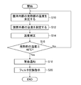
- a temperature measurement unit that measures the internal temperature, and the filter replacement time notification unit is configured to replace the filter when the temperature inside the housing measured using the temperature measurement unit is equal to or higher than a predetermined threshold. It is good also as a structure which alert
- the replacement time of the filter to be notified of the replacement time is notified based on the temperature inside the housing. As a result, it is possible to use the filter to be notified of the replacement time until its lifetime.
- the ninth aspect includes an external temperature measurement unit that measures the temperature outside the ink jet recording apparatus, and a temperature correction unit that corrects the temperature inside the housing based on the temperature outside the ink jet recording apparatus.
- the notification unit may compare the temperature inside the housing corrected using the temperature correction unit with a threshold value.
- a filter replacement time notification unit that notifies a replacement time of at least one of the first filter, the second filter, and the third filter;
- a pressure measurement unit that measures a differential pressure obtained by subtracting the pressure outside the housing from the internal pressure, and the filter replacement time notification unit has a predetermined differential pressure measured using the pressure measurement unit.
- a configuration may be adopted in which it is informed that it is time to replace the filter to be notified of the replacement time when it is equal to or greater than the threshold value.
- the replacement time of the filter to be notified of the replacement time is notified based on the differential pressure. As a result, it is possible to use the filter to be notified of the replacement time until its lifetime.
- the ninth aspect and the tenth aspect may be combined to notify the replacement time of the filter to be notified of the replacement time and the failure of the first fan.
- a filter replacement time notification unit that notifies replacement time of at least one of the first filter, the second filter, and the third filter;
- An air volume measuring unit that measures the air volume flowing into the inside of the housing, and the filter replacement time notification unit, when the air volume measured using the air volume measuring unit is equal to or less than a predetermined first threshold value, It is good also as a structure which alert
- the replacement time of the filter to be notified of the replacement time is notified based on the amount of air flowing into the housing. As a result, it is possible to use the filter to be notified of the replacement time until its lifetime.
- the replacement time notification unit determines whether or not the first filter is the replacement time and notifies the replacement time of the first filter.
- the air volume measured using the air volume measuring unit when the air volume measured using the air volume measuring unit is equal to or less than a second threshold value that is less than the first threshold value, it is time to replace the first fan. It is good also as a structure provided with the fan replacement time alerting
- the replacement time of the first fan is notified based on the airflow flowing into the housing. Thereby, the fall of the cooling efficiency inside the housing
- a thirteenth aspect is the inkjet recording apparatus according to any one of the first aspect to the twelfth aspect, and includes a fan control unit that controls the air volume of the first fan to generate an air volume necessary for cooling the electrical equipment. It is good also as a structure.
- the air volume necessary for cooling the electrical equipment is ensured.
- a fourteenth aspect is the ink jet recording apparatus according to any one of the first aspect to the twelfth aspect. It is good also as a structure provided with the fan control part which performs operation
- the number of first fans that are operated during the printing non-execution period is less than the number of first fans that are operated during the printing execution period. Therefore, the power consumption of the first fan during the non-printing period is reduced.
- the number of first fans operated during the non-printing period is preferably one or more. Due to the operation of one or more fans during the non-printing period, entry of foreign matter from the exhaust port into the housing is suppressed.
- the fifteenth aspect may be configured such that in the ink jet recording apparatus according to any one of the first aspect to the fourteenth aspect, the housing is disposed in an image forming unit that performs image formation using an ink jet head.
- the casing is disposed inside the first cover that covers the image forming unit.
- the housing may be disposed outside the first cover that covers the image forming unit.
- the image forming unit may be outside the first cover that covers the image forming unit, and may include a position of a case where foreign matter resulting from the operation of the image forming unit can enter the case.
- the casing is arranged in a paper stacking unit that stacks the paper on which images are formed using the inkjet head. Also good.
- the casing is disposed inside the second cover that covers the paper stacking unit.
- the housing may be disposed outside the second cover that covers the paper stacking unit.
- the paper stacking unit is outside the second cover that covers the paper stacking unit, and may include a position of a housing where foreign matter resulting from the operation of the paper stacking unit can enter the housing.
- the housing may be arranged at a certain distance from the heating element.
- the certain distance between the housing and the heating element can be determined from the viewpoint of whether or not the heat generated by the heating element reduces the temperature rise inside the housing.
- a heat insulating member may be disposed between the housing and the heating element.
- a cooling method is a housing for storing electrical equipment in an ink jet recording apparatus comprising a paper transport unit that transports paper and an ink jet head that ejects ink onto the paper transported using the paper transport unit.
- a cooling method for cooling the body using a first fan attached to the intake port of the housing, and forming an intake process for sucking air from the outside to the inside of the housing, and a position above the position of the intake port
- the collection process is the first And filter, the pressure loss in the initial state, and at least one of the collection efficiency of the initial state is the cooling method using a different second filter.
- matters similar to the matters specified in the second aspect to the seventeenth aspect can be appropriately combined.
- the component responsible for the process and function specified in the ink jet recording apparatus can be grasped as the component of the cooling method responsible for the process and function corresponding thereto.
- the conductive substance is collected using the first filter.
- the entry of the conductive material and the non-conductive material into the housing in which the electric device is stored is suppressed, and the electric device is short-circuited due to the conductive material that has developed conductivity due to moisture absorption. It is suppressed.
- At least a part of the substances contained in the environment in which the housing is arranged is collected using the second filter attached to the position on the intake side of the first filter.
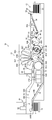
- FIG. 1 is an overall configuration diagram of an ink jet recording apparatus.
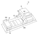
- FIG. 2 is a perspective view of the ink jet recording apparatus showing an arrangement example of the first housing and the second housing.
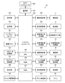
- FIG. 3 is a block diagram showing a schematic configuration of the control system.
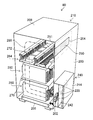
- FIG. 4 is a perspective view showing the internal structure of the first housing.
- FIG. 5 is an enlarged view of the filter unit.
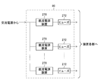
- FIG. 6 is a block diagram illustrating a configuration example of the electric device stored in the first housing.
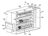
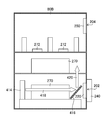
- FIG. 7 is a perspective view showing the internal structure of one side surface of the second housing.
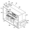
- FIG. 8 is a perspective view showing the internal structure on the other side of the second housing.
- FIG. 9 is an enlarged view of the filter portion of the second housing.
- FIG. 1 is an overall configuration diagram of an ink jet recording apparatus.
- FIG. 2 is a perspective view of the ink jet recording apparatus showing an arrangement example of the first housing and the second housing.
- FIG. 3 is a block diagram showing a schematic configuration
- FIG. 10 is a block diagram illustrating a configuration example of the electric device stored in the second housing.
- FIG. 11 is an explanatory diagram of an example of the first modification.
- FIG. 12 is an explanatory diagram of another example of the first modification.
- FIG. 13 is an explanatory diagram of an example of the second modification.
- FIG. 14 is an explanatory diagram of another example of the second modification.
- FIG. 15 is an explanatory diagram of a third modification.
- FIG. 16 is an explanatory diagram of a fourth modification.
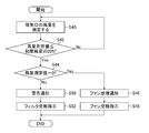
- FIG. 17 is a flowchart showing the procedure of the filter management method according to the first embodiment.
- FIG. 18 is a flowchart showing the procedure of the filter management method according to the second embodiment.
- FIG. 19 is a flowchart showing the procedure of the filter management method according to the third embodiment.
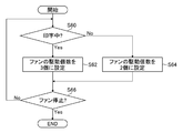
- FIG. 20 is a flowchart showing the procedure of the fan control method according to the fourth embodiment.
- orthogonality includes substantial orthogonality that can obtain the same effect as orthogonality although intersecting at an angle of less than 90 degrees or exceeding 90 degrees.
- the same term includes substantially the same thing that can obtain the same operation effect even though there is a difference.
- FIG. 1 is an overall configuration diagram of an ink jet recording apparatus.
- ink and liquid can be read each other.
- Discharge is synonymous with droplet ejection, image formation, or image recording.
- the ink jet recording apparatus 10 shown in FIG. 1 is an ink jet recording apparatus that draws an image by ink jet on a sheet S of paper.
- the ink jet recording apparatus 10 mainly includes a paper feeding unit 12, a processing liquid applying unit 14, a processing liquid drying processing unit 16, a drawing unit 18, an ink drying processing unit 20, and a paper discharge unit 24.
- a paper feeding unit 12 mainly includes a paper feeding unit 12, a processing liquid applying unit 14, a processing liquid drying processing unit 16, a drawing unit 18, an ink drying processing unit 20, and a paper discharge unit 24.
- the sheet feeding unit 12 includes a sheet feeding table 30, a soccer device 32, a sheet feeding roller pair 34, a feeder board 36, a front pad 38, and a sheet feeding drum 40.
- the feeder board 36 includes a retainer 36A and a guide roller 36B.
- the retainer 36 ⁇ / b> A and the guide roller 36 ⁇ / b> B are disposed on the transport surface on which the paper S of the feeder board 36 is transported.
- the front pad 38 is disposed between the feeder board 36 and the paper feed drum 40.
- the paper feed drum 40 has a cylindrical shape whose longitudinal direction is parallel to the rotation shaft 40B.
- the paper supply drum 40 has a length that exceeds the total length of the paper S in the longitudinal direction.
- the direction of the rotation shaft 40B of the paper supply drum 40 is a direction that penetrates the paper surface of FIG.
- the drum has a cylindrical shape, and is a conveying member that conveys the medium along the outer peripheral surface of the cylindrical shape by holding at least a part of the medium and rotating it about the central axis of the cylindrical shape.
- the paper feed drum 40 is provided with a gripper 40A.
- the gripper 40A includes a plurality of claws, a claw base, and a gripper shaft. In addition, illustration of a plurality of claws, claw bases, and gripper shafts is omitted.
- the plurality of claws of the gripper 40 ⁇ / b> A are arranged along a direction parallel to the rotation shaft 40 ⁇ / b> B of the paper feed drum 40.
- the base ends of the plurality of claws are swingably supported by the gripper shaft.
- the arrangement interval of the plurality of claws and the length of the area where the plurality of claws are arranged are determined according to the size of the paper S.
- the claw base is a member whose longitudinal direction is a direction parallel to the rotation shaft 40B of the paper feed drum 40. With respect to the longitudinal direction of the paper supply drum 40, the length of the claw base is set to be equal to or longer than the length of the region where the plurality of claws are arranged.
- the claw base is disposed at a position facing the tip portions of the plurality of claws.
- the paper feed unit 12 feeds the sheets S stacked on the paper feed tray 30 to the processing liquid application unit 14 one by one.
- the sheets S stacked on the sheet feed table 30 are pulled up one by one from the top using the soccer device 32 and are fed to the sheet feed roller pair 34.
- the paper S fed to the paper feed roller pair 34 is placed on the feeder board 36 and conveyed using the feeder board 36.
- the sheet S conveyed using the feeder board 36 is pressed against the conveying surface of the feeder board 36 using the retainer 36A and the guide roller 36B, and the unevenness is corrected.
- the inclination of the sheet S conveyed using the feeder board 36 is corrected due to the leading end abutting against the front pad 38.
- the paper S conveyed using the feeder board 36 is delivered to the paper supply drum 40.
- the leading edge of the paper S delivered to the paper supply drum 40 is gripped using the gripper 40A of the paper supply drum 40. Due to the rotation of the paper supply drum 40, the paper S is conveyed along the outer peripheral surface of the paper supply drum 40. The paper S conveyed using the paper supply drum 40 is delivered to the processing liquid application unit 14. Note that the sheet feeding drum 40 may be omitted, and the sheet S may be directly transferred from the feeder board 36 to the treatment liquid application unit.
- the treatment liquid application unit 14 includes a treatment liquid drum 42 and a treatment liquid application device 44.
- the treatment liquid drum 42 includes a gripper 42A. A configuration similar to that of the gripper 40A of the paper feed drum 40 can be applied to the gripper 42A.
- the treatment liquid drum 42 shown in FIG. 1 has a diameter twice that of the paper supply drum 40.
- the treatment liquid drum 42 is provided with two grippers 42A.
- the arrangement positions of the two grippers 42 ⁇ / b> A are positions shifted by a half circumference on the outer peripheral surface 42 ⁇ / b> C of the processing liquid drum 42.
- the treatment liquid drum 42 has a configuration in which the paper S is fixed to the outer peripheral surface 42C that supports the paper S.
- the configuration in which the sheet S is fixed to the outer peripheral surface 42C of the processing liquid drum 42 there is a configuration in which a plurality of suction holes are provided on the outer peripheral surface 42C of the processing liquid drum 42 and negative pressure is applied to the plurality of suction holes.
- the treatment liquid drum 42 can be configured in the same manner as the paper feed drum 40 except for the above.
- Reference numeral 42B denotes a rotating shaft of the treatment liquid drum 42.
- a roller coating method can be applied to the treatment liquid application device 44.
- the roller coating type processing liquid application device 44 a configuration including a processing liquid tank, a metering roller, and a coating roller may be employed.
- the processing liquid tank stores the processing liquid supplied from the processing liquid tank via the processing liquid supply channel.
- the measuring roller measures the processing liquid stored in the processing liquid tank.
- the measuring roller transfers the measured processing liquid to the application roller.
- the application roller applies the processing liquid to the paper S.
- the sheet S is transported along the outer peripheral surface 42 ⁇ / b> C of the processing liquid drum 42 due to the rotation of the processing liquid drum 42 in the state where the leading edge of the sheet S is gripped using the gripper 42 ⁇ / b> A.
- the processing liquid is applied to the sheet S conveyed along the outer peripheral surface 42 ⁇ / b> C of the processing liquid drum 42 using the processing liquid applying device 44.
- the sheet S to which the processing liquid is applied is sent to the processing liquid drying processing unit 16.
- the treatment liquid applied to the paper S has a function of aggregating the color material in the ink discharged onto the paper S by the drawing unit 18 at the subsequent stage or a function of insolubilizing the color material of the ink. Due to the treatment liquid being applied to the paper S and causing ink to be ejected, even if a general-purpose paper is used, high-quality image formation can be performed without causing landing interference or the like.
- the paper S to which the processing liquid is applied using the processing liquid application unit 14 is delivered to the processing liquid drying processing unit 16.
- the processing liquid drying processing unit 16 includes a processing liquid drying processing drum 46, a paper transport guide 48, and a processing liquid drying processing unit 50.
- the processing liquid drying processing drum 46 includes a gripper 46A. A configuration similar to that of the gripper 40A of the paper supply drum 40 can be applied to the gripper 46A.
- the processing liquid drying processing drum 46 shown in FIG. 1 has a diameter twice that of the paper feeding drum 40.
- the treatment liquid drying treatment drum 46 is provided with two grippers 46A.
- the arrangement positions of the two grippers 46 ⁇ / b> A are positions shifted by a half circumference on the outer peripheral surface 46 ⁇ / b> C of the processing liquid drying processing drum 46.
- Reference numeral 46B denotes a rotation shaft of the treatment liquid drying treatment drum 46.
- the paper transport guide 48 is disposed at a position facing the outer peripheral surface 46C of the processing liquid drying processing drum 46.
- the paper transport guide 48 is disposed below the processing liquid drying processing drum 46.
- the processing liquid drying processing unit 50 is disposed inside the processing liquid drying processing drum 46.
- the processing liquid drying processing unit 50 includes a blower that blows air toward the outside of the processing liquid drying processing drum 46 and a heating unit that heats the wind.
- a blower that blows air toward the outside of the processing liquid drying processing drum 46
- a heating unit that heats the wind.
- reference numerals of the blower unit and the heating unit are omitted.
- the leading edge of the sheet S transferred from the processing liquid application unit 14 to the processing liquid drying processing unit 16 is gripped by using a gripper 46A of the processing liquid drying processing drum 46.
- the sheet S is supported by using a sheet conveyance guide 48 on the surface opposite to the surface to which the processing liquid is applied.
- the paper S When supported using the paper transport guide 48, the paper S is in a state where the surface coated with the processing liquid faces the outer peripheral surface 46 ⁇ / b> C of the processing liquid drying processing drum 46.
- the sheet S is conveyed along the outer peripheral surface 46C of the processing liquid drying processing drum 46 due to the rotation of the processing liquid drying processing drum 46.
- the paper S that is transported using the processing liquid drying processing drum 46 and supported by the paper transport guide 48 is subjected to a drying process by blowing air heated from the processing liquid drying processing unit 50. Applied.
- the solvent component in the processing liquid applied to the paper S is removed, and a processing liquid layer is formed on the surface of the paper S to which the processing liquid is applied.
- the paper S that has been dried using the processing liquid drying processing unit 16 is delivered to the drawing unit 18.
- the drawing unit 18 includes a drawing drum 52, a paper pressing roller 54, an inkjet head 56C, an inkjet head 56M, an inkjet head 56Y, an inkjet head 56K, and an inline sensor 58.
- the drawing drum 52 includes a gripper 52A.
- the gripper 52A is disposed inside a recess provided on the outer peripheral surface 52C of the drawing drum 52.
- a configuration similar to that of the gripper 40A of the paper feed drum 40 can be applied to the configuration other than the arrangement of the gripper 52A.
- the drawing drum 52 is provided with two grippers 52 ⁇ / b> A in the same manner as the processing liquid drying processing drum 46. An arrangement similar to that of the treatment liquid drying treatment drum 46 can be applied to the arrangement of the two grippers 52A.
- the drawing drum 52 includes suction holes on the outer peripheral surface 52C that supports the paper S.
- the suction holes are arranged in a medium support area for sucking and supporting the paper S. Illustration of the suction holes and the medium support area is omitted.
- the configuration similar to that of the paper feed drum 40 can be applied to the configuration of the drawing drum 52 other than the above.
- Reference numeral 52B denotes a rotation axis of the drawing drum 52.
- the drawing drum 52 is an example of a component of the paper transport unit.
- the paper pressing roller 54 has a cylindrical shape.
- the longitudinal direction of the sheet pressing roller 54 is a direction parallel to the rotation shaft 52 ⁇ / b> B of the drawing drum 52.
- the sheet pressing roller 54 has a length exceeding the entire length of the sheet S in the longitudinal direction.
- the paper pressing roller 54 is disposed downstream of the delivery position of the paper S and upstream of the inkjet head 56C in the conveyance direction of the paper S on the drawing drum 52.
- the transport direction of the paper S may be described as a paper transport direction or a medium transport direction.
- the ink jet head 56C, the ink jet head 56M, the ink jet head 56Y, and the ink jet head 56K include a nozzle portion that ejects ink using an ink jet method.
- illustration of a nozzle part is abbreviate
- the alphabet attached to the reference numeral of the liquid discharge head represents the color of the ink.
- C represents cyan.
- M represents magenta.
- Y represents yellow.
- K represents black.
- the inkjet head 56C, the inkjet head 56M, the inkjet head 56Y, and the inkjet head 56K are disposed on the upper side of the drawing drum 52.
- the ink jet head 56C, the ink jet head 56M, the ink jet head 56Y, and the ink jet head 56K are arranged along the paper transport direction from the upstream side in the paper transport direction. Arranged in order.
- the in-line sensor 58 is disposed at a position downstream of the ink jet head 56K in the paper transport direction.
- the inline sensor 58 includes an image sensor, a peripheral circuit of the image sensor, and a light source.
- the image sensor can be a solid-state image sensor such as a CCD image sensor or a CMOS image sensor.
- CCD is an abbreviation for Charge-Coupled Device.
- CMOS is an abbreviation for Complementary Metal-Oxide Semiconductor.
- the peripheral circuit of the image sensor includes a processing circuit for the output signal of the image sensor.
- the processing circuit include a filter circuit, an amplifier circuit, or a waveform shaping circuit that removes noise components from the output signal of the image sensor. Note that illustration of a filter circuit, an amplifier circuit, or a waveform shaping circuit is omitted.
- the light source is arranged at a position where the reading object of the inline sensor can be irradiated with illumination light.
- An LED, a lamp, or the like can be applied as the light source.
- LED is an abbreviation for “light emitting diode”.
- the leading edge of the paper S delivered from the processing liquid drying processing unit 16 to the drawing unit 18 is gripped by using a gripper 52A of the drawing drum 52.
- the sheet S whose leading end is gripped using the gripper 52 ⁇ / b> A of the drawing drum 52 is conveyed along the outer peripheral surface 52 ⁇ / b> C of the drawing drum 52 due to the rotation of the drawing drum 52.
- the sheet S passes under the sheet pressing roller 54, it is pressed against the outer peripheral surface 52C of the drawing drum 52.
- the sheet S that has passed under the sheet pressing roller 54 is directly below the inkjet head 56C, inkjet head 56M, inkjet head 56Y, and inkjet head 56K, and the inkjet head 56C, inkjet head 56M, inkjet head 56Y, and inkjet head 56K.
- An image is formed using the color ink ejected from each.
- the sheet S on which an image is formed using the inkjet head 56C, the inkjet head 56M, the inkjet head 56Y, and the inkjet head 56K is read using the inline sensor 58 in the reading area of the inline sensor 58.
- the read signal of the inline sensor 58 is sent to the system controller 100 shown in FIG.
- the paper S on which an image is read using the inline sensor 58 is transferred from the drawing unit 18 to the ink drying processing unit 20. From the result of image reading using the in-line sensor 58, it is possible to determine whether or not there is a discharge abnormality.
- the ink drying processing unit 20 includes a chain gripper 64, an ink drying processing unit 68, and a guide plate 72.
- the chain gripper 64 includes a first sprocket 64A, a second sprocket 64B, a chain 64C, and a plurality of grippers 64D.
- the chain gripper 64 has a structure in which a pair of endless chains 64C are wound around a pair of first sprockets 64A and a second sprocket 64B.
- FIG. 1 shows only one of the pair of first sprocket 64A, the second sprocket 64B, and the pair of chains 64C.
- the chain gripper 64 has a structure in which a plurality of grippers 64D are disposed between a pair of chains 64C.
- the chain gripper 64 has a structure in which a plurality of grippers 64D are arranged at a plurality of positions in the paper conveyance direction.
- FIG. 1 shows only one gripper 64D among the plurality of grippers 64D arranged between the pair of chains 64C.
- the chain gripper 64 shown in FIG. 1 includes a horizontal conveyance area for conveying the paper S along the horizontal direction and an inclined conveyance area for conveying the paper S obliquely upward.
- the ink drying processing unit 68 is arranged at a position above the transport path of the paper S in the chain gripper 64.
- a configuration example of the ink drying processing unit 68 includes a configuration including a heat source such as a halogen heater or an infrared heater.
- Another configuration example of the ink drying processing unit 68 includes a configuration including a fan that blows air heated by using a heat source onto the paper S.
- the ink drying processing unit 68 may include a heat source and a fan.
- the guide plate 72 has a length that exceeds the total length of the paper S in a direction orthogonal to the paper transport direction.
- the guide plate 72 is arranged along the conveyance path in the horizontal conveyance area of the paper S using the chain gripper 64.
- the guide plate 72 is disposed at a position below the conveyance path of the paper S using the chain gripper 64.
- the guide plate 72 has a length corresponding to the length of the processing area of the ink drying processing unit 68 in the paper transport direction.
- the length corresponding to the length of the processing region of the ink drying processing unit 68 is the length of the guide plate 72 that can support the paper S on which the guide plate 72 is used during the processing of the ink drying processing unit 68. .
- the guide plate 72 may have a function of sucking and supporting the paper S.
- the leading edge of the paper S delivered from the drawing unit 18 to the ink drying processing unit 20 is gripped using the gripper 64D.
- the gripper 64D By causing at least one of the first sprocket 64A and the second sprocket 64B to rotate clockwise in FIG. 1 to cause the chain 64C to travel, the sheet S is conveyed along the travel path of the chain 64C.
- the ink drying processing is performed on the paper S using the ink drying processing unit 68.
- the paper S that has been subjected to the ink drying process using the ink drying processing unit 68 is transported using the chain gripper 64 and sent to the paper discharge unit 24.
- the chain gripper 64 shown in FIG. 1 conveys the sheet S in the upper left direction in FIG. 1 at a position downstream of the ink drying processing unit 68 in the sheet conveyance direction.
- a guide plate 73 is disposed on the conveyance path of the inclined conveyance region for conveying the sheet S in the diagonally upward left direction in FIG.
- the same member as the guide plate 72 can be applied to the guide plate 73.
- description of the structure and function of the guide plate 73 is omitted.
- the paper discharge unit 24 includes a paper discharge stand 76.
- a chain gripper 64 is applied to transport the paper S in the paper discharge unit 24.
- the paper discharge tray 76 is arranged at a position below the conveyance path of the paper S using the chain gripper 64.
- the paper discharge stand 76 can include a lifting mechanism (not shown).
- the paper discharge tray 76 can be raised and lowered according to the increase / decrease of the stacked sheets S to keep the height of the uppermost sheet S constant.
- the paper discharge unit 24 collects the paper S that has undergone a series of image forming processes. When the paper S reaches the position of the paper discharge tray 76, the gripper 64D releases the grip of the paper S. The paper S is stacked on the paper discharge tray 76.
- the inkjet recording apparatus 10 including the processing liquid application unit 14 and the processing liquid drying processing unit 16 is illustrated, but an aspect in which the processing liquid application unit 14 and the processing liquid drying processing unit 16 are omitted is also possible. is there.
- the chain gripper 64 is illustrated as a configuration for transporting the paper S after drawing.
- other transport modes such as belt transport or transport drum transport are applied to the configuration for transporting the paper S after drawing. May be.
- the ink jet recording apparatus 10 includes a first housing 80 and a second housing 82.
- casing 82 function as an electric equipment storage part in which an electric equipment is stored.
- Examples of the electrical equipment include a DC power supply device and a computer.
- the electric circuit board may be stored in the case, or the electric circuit board may not be stored in the case.
- the first casing 80 is located at the downstream side of the drawing unit 18 in the paper transport direction and at the upstream side of the paper discharge unit 24.
- the second housing 82 is arranged at a position above the paper discharge unit 24. Details of the first casing 80 and the second casing 82 will be described later.
- FIG. 2 is a perspective view of the ink jet recording apparatus showing an arrangement example of the first housing and the second housing.
- FIG. 2 shows the appearance of the ink jet recording apparatus 10 shown in FIG. In FIG. 2, the illustration of the paper feeding unit 12 shown in FIG. 1 is omitted.
- the first casing 80 shown in FIG. 2 has a rectangular parallelepiped shape.
- a metal material can be applied to the first housing 80.
- the first housing 80 is disposed in the drawing unit 18.
- the drawing unit 18 here includes the inside of the cover 18A.
- the drawing unit 18 may include the outside of the cover 18A. As an example of the outside of the cover 18 ⁇ / b> A, the position of the first housing 80 where foreign matter generated due to the operation of the drawing unit 18 can enter the first housing 80 can be cited.
- the drawing unit 18 is an aspect of an image forming unit that performs image formation.
- the cover 18A is an aspect of a first cover that covers the image forming unit.
- the first casing 80 may include an input terminal of an AC power supply and an output terminal of a DC power supply. Electrical wiring (not shown) may be connected to the input terminal of the AC power source and the output terminal of the DC power source.
- the second casing 82 shown in FIG. 2 has a rectangular parallelepiped shape.
- a metal material can be applied to the second housing 82.
- the second housing 82 is disposed in the paper discharge unit 24.
- the paper discharge unit 24 here includes the inside of the cover 20A.
- the paper discharge unit 24 may include the outside of the cover 20A. As an example of the outside of the cover 20 ⁇ / b> A, there is a position of the second housing 82 where foreign matter generated due to the operation of the paper discharge unit 24 can enter the second housing 82.
- the second casing 82 shown in FIG. 2 is arranged at a position inside the paper discharge unit 24.
- the paper discharge unit 24 is an aspect of a paper stacking unit that stacks paper.
- the cover 24A is an aspect of a second cover that covers the paper stacking unit.
- the second housing 82 may include an AC power supply input terminal, a DC power supply output terminal, and an electrical signal input / output terminal. Electrical wiring may be connected to the input terminal of the AC power supply, the output terminal of the DC power supply, and the input / output terminal of the electric signal.
- the shape and size of the first housing 80 are determined according to the size of the electrical equipment stored in the first housing 80, the quantity of electrical equipment, and the like. The same applies to the second casing 82.
- the first housing 80 is an aspect of a housing that stores electrical equipment.
- the second casing 82 is an aspect of a casing in which electrical equipment is stored.
- FIG. 3 is a block diagram showing a schematic configuration of the control system.
- the ink jet recording apparatus 10 illustrated in FIG. 3 includes a system controller 100.
- the system controller 100 includes a CPU 105, a ROM 106, and a RAM 107.
- ROM 106 and the RAM 107 shown in FIG. CPU is an abbreviation for Central Processing Unit.
- ROM is an abbreviation for Read Only Memory.
- RAM is an abbreviation for Random Access Memory.
- the system controller 100 functions as an overall control unit that comprehensively controls each unit of the inkjet recording apparatus 10. Further, the system controller 100 functions as an arithmetic unit that performs various arithmetic processes. The system controller 100 may control each unit of the inkjet recording apparatus 10 by executing a program.
- system controller 100 functions as a memory controller that controls reading and writing of data in memories such as the ROM 106 and the RAM 107.
- the inkjet recording apparatus 10 includes a communication unit 102, an image memory 104, a conveyance control unit 110, a paper feed control unit 112, a processing liquid application control unit 114, a processing liquid drying control unit 116, a drawing control unit 118, an ink drying control unit 120, A paper discharge control unit 124 and a fan control unit 126 are provided.
- the communication unit 102 includes a communication interface (not shown).
- the communication unit 102 can transmit and receive data to and from the host computer 103 connected to the communication interface.
- the image memory 104 functions as a temporary storage unit for various data including image data.
- the image memory 104 reads and writes data through the system controller 100. Image data captured from the host computer 103 via the communication unit 102 is temporarily stored in the image memory 104.
- the conveyance control unit 110 controls the operation of the conveyance unit 11 for the paper S in the inkjet recording apparatus 10.
- the transport unit 11 illustrated in FIG. 3 includes the processing liquid drum 42, the processing liquid drying processing drum 46, the drawing drum 52, and the chain gripper 64 illustrated in FIG.
- the transport unit 11 is an aspect of the medium relative movement unit.
- the paper feed control unit 112 shown in FIG. 3 controls the operation of the paper feed unit 12 in accordance with a command from the system controller 100.
- the paper feed control unit 112 controls the paper S supply start operation, the paper S supply stop operation, and the like.
- the processing liquid application control unit 114 controls the operation of the processing liquid application unit 14 according to a command from the system controller 100.
- the treatment liquid application control unit 114 controls the application amount and application timing of the process liquid.
- the processing liquid drying control unit 116 operates the processing liquid drying processing unit 16 in response to a command from the system controller 100.
- the treatment liquid drying control unit 116 controls the drying temperature, the flow rate of the dry gas, the injection timing of the dry gas, and the like.
- the drawing control unit 118 controls the operation of the drawing unit 18 in accordance with a command from the system controller 100.
- the drawing control unit 118 controls ink ejection of the inkjet head 56C, the inkjet head 56M, the inkjet head 56Y, and the inkjet head 56K illustrated in FIG.
- the drawing control unit 118 shown in FIG. 3 includes an image processing unit (not shown).
- the image processing unit forms dot data from the input image data.
- the image processing unit includes a color separation processing unit, a color conversion processing unit, a correction processing unit, and a halftone processing unit (not shown).
- the color separation processing unit performs color separation processing on the input image data.
- the input image data is expressed in RGB
- the input image data is decomposed into data for each of R, G, and B colors.
- R represents red.
- G represents green.
- B represents blue.
- the color conversion processing unit converts the image data for each color separated into R, G, and B into C, M, Y, and K corresponding to the ink colors.
- C represents cyan.
- M represents magenta.
- Y represents yellow.
- K represents black.
- the correction processing unit performs correction processing on the image data for each color converted into C, M, Y, and K.
- Examples of the correction processing include gamma correction processing, density unevenness correction processing, abnormal recording element correction processing, and the like.
- the halftone processing unit converts the image data represented by a multi-gradation number such as 0 to 255 into dot data represented by a binary or multi-value of three or more values less than the number of gradations of the input image data. Convert.
- a halftone processing rule determined in advance is applied to the halftone processing using the halftone processing unit.
- the halftone processing rule include a dither method or an error diffusion method.
- the halftone processing rule may be changed according to image recording conditions, the contents of image data, or the like.
- the drawing control unit 118 includes a waveform generation unit, a waveform storage unit, and a drive circuit (not shown).
- the waveform generator generates a drive voltage waveform.
- the waveform storage unit stores the waveform of the drive voltage.
- the drive circuit generates a drive voltage having a drive waveform corresponding to the dot data.
- the drive circuit supplies a drive voltage to the inkjet head 56C, inkjet head 56M, inkjet head 56Y, and inkjet head 56K shown in FIG.
- the discharge timing and ink discharge amount of each pixel position are determined based on the dot data generated through the processing using the image processing unit, and the discharge timing and ink of each pixel position are determined based on the dot data.
- a control signal that determines the drive voltage corresponding to the discharge amount and the discharge timing of each pixel is generated.
- the drive voltage and the control signal are supplied to the inkjet head 56C, the inkjet head 56M, the inkjet head 56Y, and the inkjet head 56K. Based on the drive voltage and the control signal, dots are recorded on the paper S using the ink ejected from the inkjet head 56C, the inkjet head 56M, the inkjet head 56Y, and the inkjet head 56K.
- the ink drying control unit 120 controls the operation of the ink drying processing unit 20 in accordance with a command from the system controller 100.
- the ink drying control unit 120 controls the drying gas temperature, the flow rate of the drying gas, or the ejection timing of the drying gas.
- the paper discharge control unit 124 controls the operation of the paper discharge unit 24 in accordance with a command from the system controller 100.
- the paper discharge control unit 124 controls the operation of the lifting mechanism according to the increase / decrease of the paper S when the paper discharge tray 76 shown in FIG.
- the fan control unit 126 controls the operation of the fan 26 in accordance with a command from the system controller 100.
- the fan control unit 126 controls the operation start timing, operation stop timing, and rotation speed of the fan 26.
- the fan 26 shown in FIG. 3 includes a first casing 80 shown in FIGS. 1 and 2 and a plurality of fans attached to the second casing 82 shown in FIGS. 1 and 2.
- FIG. 1 and FIG. 2 illustration of a plurality of fans is omitted.
- the plurality of fans attached to the first housing 80 are illustrated with reference numeral 220 in FIG.
- the plurality of fans attached to the second housing 82 are illustrated with reference numeral 320 in FIG.
- the inkjet recording apparatus 10 shown in FIG. 3 includes an operation unit 130, a display unit 132, a parameter storage unit 134, and a program storage unit 136.
- the operation unit 130 includes operation members such as operation buttons, a keyboard, or a touch panel.
- the operation unit 130 may include a plurality of types of operation members. The illustration of the operation member is omitted.
- Information input via the operation unit 130 is sent to the system controller 100.
- the system controller 100 executes various processes in accordance with information sent from the operation unit 130.
- the display unit 132 includes a display device such as a liquid crystal panel and a display driver. In FIG. 3, illustration of the display device and the display driver is omitted. In response to a command from the system controller 100, the display unit 132 causes the display device to display various information such as various setting information of the device or abnormality information.
- the parameter storage unit 134 stores various parameters used in the inkjet recording apparatus 10. Various parameters stored in the parameter storage unit 134 are read out via the system controller 100 and set in each unit of the apparatus.
- the program storage unit 136 stores a program used for each unit of the inkjet recording apparatus 10. Various programs stored in the program storage unit 136 are read out via the system controller 100 and executed in each unit of the apparatus.
- the detection unit 140 illustrated in FIG. 3 includes a sensor provided in each unit of the inkjet recording apparatus 10 and a peripheral circuit of the sensor.
- Examples of the detection unit 140 include a temperature sensor, a pressure sensor, and a position detection sensor.
- the detection unit 140 may include a processing circuit for detection signals output from various sensors.
- the filter management unit 142 executes a filter management method program to be described later, and manages the filter unit.
- the filter unit is shown in FIG.
- the filter unit is shown in FIG.
- FIG. 3 each part is listed for each function.
- Each unit shown in FIG. 3 can be appropriately integrated, separated, combined, or omitted.
- FIG. 3 The hardware structure of various processing units shown in FIG. 3 is the following various processors.
- Various processors include a CPU, a PLD, and an ASIC.
- the various processing units illustrated in FIG. 3 are substantially responsible for processing, but the term of the processing unit may not be used in the name.
- a term such as a control unit may also be included in the concept of various processing units.
- Examples of the various processing units shown in FIG. 3 include a conveyance control unit 110, a paper feed control unit 112, and a drawing control unit 118.
- the control part includes what is described as a processing unit using English notation. Processors include those written as processor using English notation.
- CPU is a general-purpose processor that executes software and functions as various processing units. Software can be read as a program.
- the PLD is a processor whose circuit configuration can be changed after manufacture.
- An example of PLD is FPGA.
- PLD is an abbreviation for Programmable Logic Device.
- FPGA is an abbreviation for Field Programmable Gate Array.
- ASIC is a processor having a circuit configuration specifically designed to execute a specific process, or a dedicated electric circuit.
- ASIC is an abbreviation for Application Specific Integrated Circuit.
- One processing unit may be composed of one of the various processors described above.
- One processing unit may be configured using two or more processors of the same type, or two or more processors of different types. Examples of two or more processors of the same type include a plurality of FPGAs. An example of two or more processors of different types is a combination of a CPU and an FPGA.
- a plurality of processing units may be configured using a single processor.
- an aspect in which one processor is configured using a combination of one or more CPUs and software, and one processor functions as a plurality of processing units. can be mentioned.
- Specific examples include a server and a computer such as a client.
- a processor that realizes the functions of the entire system including the plurality of processing units with a single IC chip is used.
- a specific example is a system on chip.
- System-on-chip includes those described as System On Chip or SoC using English notation.
- IC is an abbreviation for Integrated Circuit.
- the various processing units shown in FIG. 3 are configured using one or more of the various processors described above as a hardware structure.
- the hardware structure of the various processors described above is more specifically an electric circuit in which circuit elements such as semiconductor elements are combined.
- the electric circuit includes what is described as circuit using English notation.
- FIG. 3 Specific examples of the various storage units illustrated in FIG. 3 include a memory, a storage element, and a storage device.
- a storage device in which various programs are stored can be given.
- [Inkjet head structure] The same structure may be applied to the inkjet head 56C, the inkjet head 56M, the inkjet head 56Y, and the inkjet head 56K.
- the reference numerals are omitted and the inkjet head is described.
- the inkjet head may have a structure in which a plurality of head modules are connected in the width direction of the paper S, which is a direction orthogonal to the transport direction of the paper S.
- the same structure may be applied to the plurality of head modules constituting the inkjet head.
- the head module may be a single unit or function as a liquid discharge head.
- the transport direction of the paper S may be described as the paper transport direction.
- the width direction of the paper S may be described as the paper width direction.
- the inkjet head may be a line-type liquid discharge head in which a plurality of nozzle portions are arranged over a length equal to or greater than the total length of the paper S in the paper width direction.
- the nozzle part may include a nozzle opening formed on the liquid discharge surface and a nozzle communication path connected to the nozzle opening.
- the liquid discharge surface is a surface facing the outer peripheral surface 52C of the drawing drum 52 shown in FIG.
- the head module may have an ink supply unit including an ink supply chamber and an ink circulation chamber on the upper side opposite to the liquid ejection surface.
- the ink supply chamber may be connected to the ink tank via a supply-side individual flow path.
- the ink circulation chamber may be connected to the recovery tank via a recovery side individual flow path.
- a plurality of nozzle openings may be arranged on the liquid ejection surface of one head module by applying a two-dimensional arrangement.
- the head module has an end surface on the long side along the V direction having an inclination of an angle ⁇ with respect to a direction orthogonal to the medium conveyance direction, and a short along the W direction having an inclination of the angle ⁇ with respect to the medium conveyance direction.
- a plane shape of a parallelogram having an end surface on the side may be used.
- a plurality of nozzle openings may be arranged in a matrix in the row direction along the V direction and the column direction along the W direction.
- a plurality of nozzle openings may be arranged along a row direction along a direction orthogonal to the medium conveyance direction and a column direction obliquely intersecting the direction orthogonal to the medium conveyance direction.
- the matrix arrangement of nozzle openings refers to a direction orthogonal to the medium conveyance direction in which a plurality of nozzle openings are projected in a direction orthogonal to the medium conveyance direction and the plurality of nozzle openings are arranged along a direction orthogonal to the medium conveyance direction.
- the nozzle openings are arranged at uniform intervals between the nozzle openings.
- the head module may apply a piezo jet method in which ink in a pressure chamber is pressurized using a piezoelectric element and ink is ejected from a nozzle opening.
- the head module may apply a thermal method in which the ink in the pressure chamber is heated using a heater, and ink is ejected from the nozzle opening using a film boiling phenomenon.
- the nozzle portion represents a concept including a nozzle opening.
- the nozzle opening and the nozzle portion can be replaced with each other.
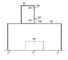
- FIG. 4 is a perspective view showing the internal structure of the first housing.
- the first housing 80 shown in FIG. 4 has a rectangular parallelepiped shape.
- FIG. 4 is a view of the first housing 80 with the back plate removed, as viewed from the back side.
- the front surface, the back surface, the side surface, the top surface, and the bottom surface of the first housing 80 are the first housing in a state where the first housing 80 is disposed at the position where the first housing 80 illustrated in FIG. 1 is disposed.
- the front, back, side, top, and bottom of the body 80 are represented. The same applies to the second casing 82.
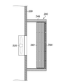
- the side plate 200 of the first housing 80 has an air inlet 202 and an air outlet 204 formed therein.
- the exhaust port 204 is formed at a position above the intake port 202. In other words, the intake port 202 is disposed closer to the bottom plate 206 than the exhaust port 204.
- the distance from the air inlet 202 to the bottom plate 206 is determined from the viewpoint of suppressing entry of dust and deposits such as dust.
- the distance from the intake port 202 to the exhaust port 204 is determined from the viewpoint of securing a sufficient amount of gas inside the first housing 80.
- the side surface of the first housing 80 is an aspect of a wall surface on which an intake port and an exhaust port are formed.
- a plurality of fans 220 are attached to the intake port 202.
- the plurality of fans 220 are arranged along the direction from the front plate 210 to the back plate of the first housing 80.
- the fan 220 closest to the back plate is illustrated using a solid line, and the other fans 220 are illustrated using a dotted line.
- the plurality of fans 220 are attached to the inner side surface of the first housing 80.
- the plurality of fans 220 may be attached to the inside of the air inlet 202 or may be attached to a surface on the outer side of the first housing 80.
- the plurality of fans 220 blows air from the outside to the inside of the first housing 80. Then, the pressure inside the first housing 80 exceeds the pressure outside the first housing 80, and the inside of the first housing 80 is positively pressurized.
- the fan 220 is an aspect of the first fan. Intake into the first housing 80 using the fan 220 is an aspect of an intake process constituting a cooling method. Exhaust from the exhaust port 204 is an aspect of an exhaust process that constitutes a cooling method.
- the filter unit 240 is attached to the intake port 202.
- the filter unit 240 includes a conductive material collection filter 242 and a coarse dust filter 244.
- a coarse dust filter 250 is attached to the exhaust port 204.
- the exhaust port 204 may be a combination of the coarse dust filter 250 and the conductive material collection filter 242 as in the filter unit 240. Details of the filter unit 240 and the coarse dust filter 250 will be described later.
- the conductive material collection filter 242 is an embodiment of the first filter.
- the coarse dust filter 244 is an aspect of the second filter.
- the coarse dust filter 250 is an embodiment of the third filter.
- the collection of foreign matter using the filter unit 240 is one aspect of a collection process that constitutes a cooling method.
- the collection of the conductive substance using the conductive substance collection filter 242 is one aspect of the first collection process that constitutes the collection process.
- the collection of foreign matter using the coarse dust filter 244 is an aspect of the second collection step that constitutes the collection step.
- the interior of the first housing 80 has a three-story structure.
- a plurality of DC power supply devices 270 are arranged on the first floor portion 260 of the first housing 80 and the second floor portion 262 of the first housing 80.
- a plurality of fuses 272 are arranged on the third floor 264 of the first housing 80.
- DC power supply 270 is an aspect of electrical equipment.
- the fuse 272 is an aspect of electrical equipment.
- the plurality of DC power supply devices 270 and the fuses 272 are forcibly cooled using the air flow generated in the first housing 80.
- the air heated due to the heat generated by the plurality of DC power supply devices 270 and the fuse 272 moves to the upper side inside the first housing 80.
- the air that has moved to the upper side inside the first housing 80 is discharged to the outside of the first housing 80 through the exhaust port 204 due to the flow of air from the inside of the first housing 80 to the outside.
- symbol 280 to FIG. 4 and illustrated using the dashed-dotted line has shown the flow of the air inside the 1st housing
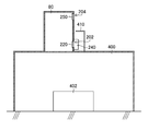
- FIG. 5 is an enlarged view of the filter unit.
- the conductive substance collection filter 242 and the coarse dust filter 244 are arranged in the order of the conductive substance collection filter 242 and the coarse dust filter 244 from the side plate 200 side.
- the filter unit 240 includes a case 246.
- the conductive material collection filter 242 and the coarse dust filter 244 are supported using a case 246.
- the case 246 is configured to be detachable from the side plate 200 using a joining member such as a screw.
- An example of the distance between the conductive material collection filter 242 and the fan 220 is 30 millimeters.
- the distance between the conductive material collection filter 242 and the fan 220 may be 15 millimeters or more and 45 millimeters.
- the filter unit 240 is preferably attached to the outside of the first housing 80.
- the filter unit 240 collects substances derived from the paper S shown in FIG. 1, substances derived from the installation environment of the inkjet recording apparatus 10, substances derived from printing of the inkjet recording apparatus 10, and the like.
- An example of a substance derived from the paper S is paper dust.
- Examples of the substance derived from the installation environment of the inkjet recording apparatus 10 include a substance contained in a humidifying mist used when the installation environment of the inkjet recording apparatus 10 is humidified.
- An example of a substance contained in the humidified mist is calcium hypochlorite.
- Humidification mist is one aspect of moisture in the environment in which the housing is placed.
- Examples of substances derived from printing by the inkjet recording apparatus 10 include powder for suppressing stacking of printed paper S.
- substances contained in the powder include talc and calcium carbonate.
- the filter unit 240 has a function of collecting substances that may be included in the use environment of the ink jet recording apparatus according to a liquid such as ink used and a medium such as paper used. .
- the conductive material collection filter 242 illustrated in FIG. 5 mainly has a function of collecting a conductive material.
- a conductive substance is a substance that develops conductivity due to moisture absorption.
- An example of the conductive substance is a deliquescent substance.
- An example of a deliquescent material is chloride.
- the conductive material collection filter 242 is a salt-resistant filter.
- the salt-resistant filter includes a filter medium that absorbs liquefied chloride.
- a filter medium having a function of suppressing the increase in pressure loss due to the collection of the liquefied chloride by suppressing the liquefied chloride from being formed into a film is mentioned.
- the conductive material collection filter 242 may collect the material that has passed through the coarse dust filter 244.
- the conductive material collection filter 242 may collect a non-conductive material.
- the conductive material collection filter 242 collects the conductive material, and the intrusion of the conductive material into the first housing 80 is suppressed. If it does so, failure of the electric equipment resulting from the adhesion to the electric equipment of the electroconductive substance which absorbed moisture and expressed conductivity will be controlled.
- Coarse dust filter 244 shown in FIG. 5 collects substances that may cause an increase in pressure loss of conductive substance collection filter 242 on the intake side of conductive substance collection filter 242.
- the coarse dust filter 244 functions as a pre-filter for the conductive substance collection filter 242.
- the conductive substance collection filter 242 and the coarse dust filter 244 may be attached to the inside of the first housing 80.
- the coarse dust filter 244 is attached to an upstream position in the air blowing direction of the fan 220, and A conductive material collection filter 242 is attached to a downstream position in the blowing direction.
- the coarse dust filter 244 may be attached to the intake side of the fan 220 and the conductive material collection filter 242 may be attached to the exhaust side of the fan 220 with the fan 220 interposed therebetween. That is, the filter unit 240 may incorporate the fan 220.
- the initial pressure loss is the pressure loss of the filter in the initial state that is the state before use.
- a filter having an initial pressure loss of 5.0 Pascal or more and 20.0 Pascal or less under a condition where the thickness is 10 millimeters or more and 20 millimeters or less and the standard wind speed is 1.5 meters per second can be cited.
- the pressure loss can be calculated by applying the standard wind speed or the rated wind speed and subtracting the gas pressure on the downstream side from the gas pressure on the upstream side in the gas flow direction of the filter.
- the standard wind speed or the rated wind speed is a wind speed determined in advance as a test condition for pressure loss.
- the pressure loss can be measured using a differential pressure gauge.
- the unit of standard wind speed and rated wind speed is meters per second.
- the unit of pressure loss is Pascal.
- the coarse dust filter 244 is an air filter in which the size of a substance that can be collected is larger than that of the conductive substance collection filter 242.
- grains used for a test is 10 micrometers or more and 20 micrometers or less, and the average collection efficiency measured using the mass method is 20 to 90 percent.
- Examples of the material of the coarse dust filter 244 include vinylidene chloride fiber, aluminum foil, polyether polyurethane, polyester polyurethane foam, and polyvinylidene chloride plastic.
- the coarse dust filter 244 is one mode of the second filter in which the pressure loss in the initial state is equal to or lower than the pressure loss in the initial state of the first filter. Moreover, the coarse dust filter 244 is an aspect of the second filter whose initial collection efficiency is equal to or lower than the initial collection efficiency of the first filter.
- the coarse dust filter 250 collects foreign matter that can enter the first housing 80 from the exhaust port 204 during the stop period of the fan 220.
- the foreign matter that can be collected by the coarse dust filter 244 includes at least a substance that can be collected using the filter unit 240.
- the coarse dust filter 250 is supported using a support frame 251.
- the coarse dust filter 250 is attached to the inner surface of the side plate 200.
- the coarse dust filter 250 may be attached to the outer surface of the side plate 200.
- the coarse dust filter 250 is an embodiment of a third filter in which the pressure loss in the initial state is equal to or lower than the pressure loss in the initial state of the first filter.
- the coarse dust filter 250 is an aspect of a third filter whose initial collection efficiency is equal to or lower than the initial collection efficiency of the first filter.
- one filter unit 240 is provided for a plurality of fans 220 is illustrated, but an embodiment in which one filter unit 240 is provided for one fan 220 is also possible. Further, the fan 220 and the filter unit 240 may be integrally configured.
- FIG. 6 is a block diagram illustrating a configuration example of the electric device stored in the first housing.
- the first casing 80 stores a plurality of DC power supply devices 270 and a plurality of fuses 272.
- the DC power supply device 270 is an electric device that receives an AC power supply and outputs a DC power supply.
- AC power sources include three-phase 230 volts, single-phase 200 volts, and single-phase 100 volts.
- Examples of the output voltage of the DC power supply device 270 include 48 volts, 24 volts, and 5 volts.
- the standard of the fuse 272 is determined according to the cutoff current set for the electrical equipment to be electrically connected.
- the fuse exemplified in this embodiment can be replaced with another power interruption member such as a breaker.
- another power interruption member such as a breaker.
- the plurality of fuses 272 illustrated in FIG. 4 may be connected to electrical wiring that transmits an AC power supply.
- the first housing 80 functions as a power supply box provided with electric devices that supply power to each part of the ink jet recording apparatus 10 shown in FIG. 1.
- electric devices that supply power to each part of the ink jet recording apparatus 10 shown in FIG. 1. Examples of each part of the apparatus include a solenoid valve, a sensor, illumination, and various electric devices.
- FIG. 7 is a perspective view showing the internal structure of one side surface of the second housing.
- FIG. 7 illustrates a state in which one side plate of the second housing 82 is removed.
- the second housing 82 shown in FIG. 7 is different from the first housing 80 shown in FIG.
- the second casing 82 has an exhaust port 304 formed in the upper surface plate 308.
- the second housing 82 shown in FIG. 7 includes two exhaust ports 304.
- the second housing 82 includes the exhaust port 304 on each of the one side surface and the other side surface shown in FIG.
- Reference numeral 350 denotes a coarse dust filter provided in the exhaust port 304.
- the coarse dust filter 350 has the same function as the coarse dust filter 250 shown in FIG.
- the exhaust port 304 may be a combination of the coarse dust filter 350 and the conductive substance collection filter 242.
- the side surface of the second housing 82 is an aspect of the wall surface on which the air inlet is formed.
- the upper surface of the second housing 82 is an aspect of a wall surface on which an exhaust port is formed.
- the fan 320 is an aspect of the first fan.
- the conductive material collection filter 342 is an embodiment of the first filter.
- the coarse dust filter 344 is an aspect of the second filter.
- the coarse dust filter 350 is an embodiment of the third filter.
- the intake from the intake port 302 is one aspect of the intake process that constitutes the cooling method.
- Exhaust from the exhaust port 304 is one aspect of an exhaust process that constitutes a cooling method.
- the collection of foreign matter using the filter unit 440 is one aspect of a collection step that constitutes a cooling method.
- the collection of the conductive substance using the conductive substance collection filter 342 is an aspect of the first collection process that constitutes the collection process.
- the collection of foreign matter using the coarse dust filter 344 is an aspect of the second collection step that constitutes the collection step.
- a plurality of electromagnetic contactors 374 are stored on one side of the second casing 82 shown in FIG. 7 as electrical equipment.
- the magnetic contactor 374 is an electric device that switches between a connected state and a disconnected state of an electric circuit.
- the electromagnetic contactor 374 includes a relay that switches between contact and non-contact of electrical contacts based on a control signal.
- a plurality of electromagnetic contactors 374 are disposed on each of the first floor part 360, the second floor part 362, and the third floor part 364.
- the magnetic contactor 374 performs switching of electrical signal wiring for transmitting electrical signals.
- the magnetic contactor 374 may transmit power wiring switching for transmitting power to a power supply device, a motor, and the like.
- an air inlet 302 is formed in the front plate 310.
- a plurality of fans (not shown in FIG. 7) are attached to the air inlet 302. The plurality of fans are illustrated with reference numeral 320 in FIG.
- the filter unit 340 illustrated in FIG. 7 has a filter unit 340 attached to the air inlet 302.
- the filter unit 340 illustrated in FIG. 7 includes the coarse dust filter 344 illustrated in FIG. 7 and the conductive material collection filter (not illustrated in FIG. 7), similarly to the filter unit 240 illustrated in FIG.
- the conductive material collecting filter is illustrated with reference numeral 344 in FIG.
- an arrow line denoted by reference numeral 380 and illustrated using a one-dot chain line indicates an internal air flow on one side of the second housing 82.
- a reference numeral 306 indicates a bottom plate of the second casing 82.
- Reference numeral 312 denotes a back plate of the second housing 82.
- FIG. 8 is a perspective view showing the internal structure of the other side surface of the second housing.
- FIG. 8 illustrates a state in which the other side plate of the second casing 82 is removed.
- the other side surface of the second housing 82 is separated from the one side shown in FIG.
- the DC power supply device 370 and the computer 376 are stored as electric devices on the other side surface side of the second casing 82 shown in FIG.
- An arrow line denoted by reference numeral 382 in FIG. 8 and illustrated using a one-dot chain line indicates an internal air flow on the other side surface side of the second housing 82.
- FIG. 9 is an enlarged view of the filter part of the second casing.
- the filter unit 340 illustrated in FIG. 9 includes a conductive material collection filter 342 and a coarse dust filter 344, similarly to the filter unit 240 illustrated in FIG.
- the arrangement of the conductive substance collection filter 342 shown in FIG. 9 is the same as the arrangement of the conductive substance collection filter 242 provided in the filter unit 240 of the first housing 80 shown in FIG. Further, the function of the conductive substance collection filter 342 shown in FIG. 9 is the same as the function of the conductive substance collection filter 242 provided in the filter unit 240 of the first housing 80 shown in FIG.
- the arrangement of the coarse dust filter 344 shown in FIG. 9 is the same as the arrangement of the coarse dust filter 244 provided in the filter unit 240 of the first housing 80 shown in FIG. Further, the function of the coarse dust filter 344 shown in FIG. 9 is the same as the function of the coarse dust filter 244 provided in the filter unit 240 of the first housing 80 shown in FIG. Here, description of the conductive material collection filter 342 and the coarse dust filter 344 illustrated in FIG. 9 is omitted.
- the plurality of fans 320 shown in FIG. 9 are attached to the outer surface of the second housing 82.
- the plurality of fans 320 are covered with the case 346 of the filter unit 340.
- the plurality of fans 320 may be attached to the inside of the air inlet 302 or may be attached to a surface on the inner side of the second housing 82.
- the plurality of fans 320 are arranged along the vertical direction from the top plate 308 to the bottom plate 306 of the second housing 82.
- the plurality of fans 320 are arranged along the direction from the front plate 310 to the back plate 312 of the second housing 82.
- FIG. 9 the illustration of the top plate 308, bottom plate 306, front plate 310, and back plate 312 of the second housing 82 is omitted.
- the top plate 308, bottom plate 306, front plate 310, and back plate 312 of the second housing 82 are illustrated in FIGS. Note that reference numeral 300 in FIG. 9 indicates a side plate of the second housing 82.
- FIG. 10 is a block diagram illustrating a configuration example of the electric device stored in the second housing.
- the second casing 82 stores a plurality of DC power supply devices 370, a plurality of electromagnetic contactors 374, and a computer 376.
- MC shown in FIG. 10 is an abbreviation for Electromagnetic Contactor, which is an English notation representing an electromagnetic contactor.
- the computer 376 can function as the host computer 103 shown in FIG.
- the command signal output from the computer 376 is transmitted to each part of the apparatus via the electrical wiring 377 shown in FIG.
- an electromagnetic contactor 374 is connected to the electrical wiring 377 connected to the computer 376.
- the electromagnetic contactor 374 illustrated in FIG. 7 may be connected to an output signal wiring of a control device other than the computer 376.
- the electromagnetic contactor 374 functions as a switch for turning on / off the command signal.
- the electromagnetic contactor 374 switches whether or not to transmit the control signal via each electrical wiring 377 based on a control signal input via an electrical wiring (not shown).
- the DC power supply device 370 has the same function as the DC power supply device 270 shown in FIG. Here, illustration of the DC power supply device 370 is omitted.
- the electrical wiring 379 connected to the DC power supply device 370 may be connected to an electrical circuit breaker such as a fuse and a breaker.
- the configuration of the electric device in the first casing 80 shown in FIG. 6 and the configuration of the electric device in the second casing 82 shown in FIG. 10 are examples, and changes such as addition and deletion are possible.
- the filter portion 240 is provided in the air inlet 302 of the first housing 80 in which the electrical equipment is stored.
- the filter unit 240 includes a conductive material collection filter 242. As a result, it is possible to collect the conductive material that may cause a failure of the electric device.
- the fan 220 is provided in the air inlet 302 of the first housing 80, and air outside the first housing 80 is introduced into the first housing 80. Thereby, due to the positive pressure inside the first housing 80, the entry of foreign matter into the first housing 80 is suppressed.
- the exhaust port 204 is provided at a position above the intake port 202. As a result, efficient forced cooling of the electrical equipment stored inside the first housing 80 is possible due to the generation of an air flow from the bottom to the top inside the first housing 80. is there.
- the filter unit 240 includes a coarse dust filter 244 outside the conductive material collection filter 242.
- the use of the coarse dust filter 244 collects substances that can cause an increase in pressure loss of the conductive substance collection filter 242, thereby extending the life of the conductive substance collection filter 242. Contribute.
- FIG. 11 is an explanatory diagram of an example of the first modification.
- the first housing 80 shown in FIG. 11 is arranged in an area where there is little foreign matter.
- the first housing 80 shown in FIG. 11 is disposed at a position separated from the foreign matter generation source 402 by using the partition member 400.
- a conveyance section of the paper S such as the drawing drum 52 shown in FIG.
- Examples of the region with a small amount of foreign matter include the outside of the cover 18A that covers the drawing unit 18 shown in FIG. 1 and the outside of the cover 24A that covers the paper discharge unit 24 shown in FIG.
- FIG. 12 is an explanatory diagram of another example of the first modification.
- a shielding member 410 is disposed in the vicinity of the air inlet 202.
- the vicinity of the air inlet 202 is a range in which the effect of suppressing the entry of foreign matter from the air inlet 202 due to the arrangement of the shielding member 410 is obtained.
- the shielding member 410 is arranged at a certain distance from the intake port 202.
- the fixed distance from the air intake 202 does not inhibit the intake from the air intake 202 to the inside of the first housing 80, and the effect of suppressing the entry of foreign matter from the air intake 202 to the inside of the first housing 80. Is the distance obtained.
- the first modification entry of foreign matter from the air inlet 202 into the first housing 80 is suppressed. Thereby, the cooling efficiency of the electric equipment can be improved. In addition, this contributes to extending the life of the conductive material collection filter 242.
- FIG. 13 is an explanatory diagram of an example of the second modification.
- the first housing 80A according to the second modification includes a fan 411 inside the first housing 80A.
- FIG. 13 illustrates an aspect in which the first housing 80 ⁇ / b> A includes a plurality of fans 411.
- the blowing direction of the fan 411 is upward.
- An arrow line denoted by reference numeral 412 in FIG. 13 is a blowing direction of the fan 411.
- the blowing direction of the fan 411 is an obliquely upward direction in which the angle formed with the vertically upward direction is less than 90 degrees when the direction illustrated using the arrow line denoted by reference numeral 412 in FIG. Also good.
- FIG. 14 is an explanatory diagram of another example of the second modified example.
- the first housing 80B illustrated in FIG. 14 includes a fan 414 and a regulating member 416.
- the air blowing direction of the fan 414 is a direction orthogonal to the vertically upward direction, and an arrow line denoted by reference numeral 418 represents the air blowing direction of the fan 414.
- the regulating member 416 has a function of changing the blowing direction of the fan 414 from sideways to upward.
- the restricting member 416 shown in FIG. 14 has a flat plate shape.
- the regulating member 416 may be a member having a curved surface such as a spherical surface.
- the restricting member 416 preferably has a shape and arrangement that does not restrict the blowing of air to the DC power supply device 270 using the fan 220.
- the fan 414 is an aspect of a second fan that blows air upward in the housing.
- FIG. 15 is an explanatory diagram of a third modification.
- the DC power supply device 270A shown in FIG. 15 is provided in the first casing 80 shown in FIG. 4 and the second casing 82 shown in FIG.
- the blowing direction of the fan 420 is upward in the state provided in the first housing 80 shown in FIG. 4 and the second housing 82 shown in FIG.
- An arrow line denoted by reference numeral 422 in FIG. 15 represents the blowing direction of the fan 420.
- the fan 420 is an aspect of a third fan that blows air toward the upper side of the housing.
- FIG. 16 is an explanatory diagram of a fourth modification.
- the first housing 80 shown in FIG. 16 is disposed with a gap 432 between the first housing 80 and the heating element 430.
- An example of the heating element 430 is a heat source such as a heater.
- the gap 432 is an example of a certain distance from the heating element.
- the gap between the first casing 80 and the heating element 430 is determined from the viewpoint of the temperature of the heating element 430 and the cooling efficiency of the first casing 80.
- the fixed distance between the first housing 80 and the heating element 430 is whether the heat generated by the heating element 430 reduces the effect on the temperature rise inside the first housing 80. It is possible to decide from the point of view.
- the air inlet 202 is disposed at a position where the influence of heat is small.
- a heat insulating member 434 may be provided in the gap 432 between the first housing 80 and the heating element 430.
- the heat insulating member 434 should just be arrange
- the heat insulating member 434 may be in close contact with the heating element 430.
- the heat insulating member 434 is arranged at a certain distance from the air inlet 202.
- the fixed distance from the air inlet 202 is a distance that does not inhibit the air intake from the air inlet 202 into the first housing 80 and can obtain the heat insulating effect of the first housing 80.
- the first casing 80 is arranged with a gap from the heat source. Thereby, the cooling efficiency of the first housing 80 can be improved.
- This modification can also be applied to the second housing 82 shown in FIG.
- the entire surface of the electric substrate used in the electric device such as the DC power supply device 270 shown in FIG. 4 or the energizing portion is made of an insulating material such as acrylic, urethane, and silicon. Coated.
- a coating is an embodiment of a coating.
- the electrical board includes both a state in which an electrical component is mounted on the electrical circuit board and a state in which no electrical component is mounted on the electrical circuit board.
- the failure of the electrical device due to the short circuit can be suppressed.
- FIG. 17 is a flowchart showing the procedure of the filter management method according to the first embodiment.
- the filter management method according to the first embodiment described below monitors the temperature of the heat generating part inside the housing, and issues a warning and instructs the replacement of the filter part when the temperature of the heat generating part is equal to or higher than a threshold value.
- the housing is a general term for the first housing 80 shown in FIG. 4 and the second housing 82 shown in FIG.
- the heat generating part inside the housing can be an electrical device having the highest temperature among the electrical devices provided inside the housing.
- the filter section here is a general term for the filter section 240 shown in FIG. 4 and the filter section 340 shown in FIG.
- the filter unit 240 shown in FIG. 4 and the filter unit 340 shown in FIG. 7 may be managed individually or collectively.
- the detection unit 140 shown in FIG. 3 measures the temperature of the heat generating part inside the housing.
- An example of the detection unit 140 is a temperature sensor provided inside the housing.
- the temperature sensor may be a contact type or a non-contact type.
- Information on the temperature of the heat generating part inside the housing measured in the internal temperature measuring step S10 of FIG. 17 is sent to the filter management part 142 shown in FIG.
- the detection unit 140 shown in FIG. 3 measures the temperature outside the ink jet recording apparatus 10 shown in FIG.
- a temperature sensor provided outside the inkjet recording apparatus 10 illustrated in FIG. 1 can be cited.
- Information on the temperature outside the ink jet recording apparatus 10 shown in FIG. 1 measured in the internal temperature measuring step S10 in FIG. 17 is sent to the filter management unit 142 shown in FIG.
- the internal temperature measurement step S10 and the external temperature measurement step S12 in FIG. 17 may be performed in parallel.
- the temperature of the heat generating part inside the housing is measured, and in the external temperature measurement step S12, the temperature outside the ink jet recording apparatus 10 shown in FIG. It progresses to temperature correction process S14.
- the filter management unit 142 shown in FIG. 3 corrects the temperature of the heat generating part inside the housing using the temperature outside the ink jet recording apparatus 10 shown in FIG.
- the temperature of the heat generating part inside the housing there is correction that subtracts the temperature outside the ink jet recording apparatus 10 shown in FIG. 1 from the temperature of the heat generating part inside the housing.
- the process proceeds to the determination step S16.
- the filter management unit 142 illustrated in FIG. 3 determines whether or not the corrected temperature of the heat generating unit inside the casing is equal to or higher than a threshold temperature. In the present embodiment, 45 ° C. is applied as the threshold temperature. As the threshold temperature, any temperature determined from the viewpoint of the cooling efficiency of the housing can be applied.
- the determination step S16 of FIG. 17 when the corrected temperature of the heat generating part inside the casing is equal to or lower than the threshold temperature, the determination is No. In the case of No determination, the process returns to the internal temperature measurement step S10, and each process from the internal temperature measurement step S10 to the determination step S16 is repeatedly executed.
- the determination step S16 if the corrected temperature of the heat generating part inside the casing is equal to or higher than the threshold temperature, the determination is Yes.
- Yes determination it is considered that as a result of the performance of the filter unit being deteriorated, the effect of cooling using the fan is weakened, and the temperature of the heat generating unit inside the housing is increased.
- the fans here are a generic term for the plurality of fans 220 shown in FIG. 4 and the plurality of fans 320 shown in FIG.
- the filter management unit 142 illustrated in FIG. 3 notifies the warning using the display unit 132.
- the warning here may be a warning for notifying the temperature rise of the heat generating part inside the housing.
- a warning for notifying the performance degradation of the filter unit may be used.
- character information, sound information, or the like can be applied.
- the sound information is a concept including sound information and a warning sound.
- the process proceeds to the filter replacement instruction step S20.
- the filter management unit 142 illustrated in FIG. 3 instructs the replacement of the filter unit using the display unit 132.
- the replacement instruction of the filter unit may be character information or voice information.
- the filter management unit 142 shown in FIG. 3 notifies the warning using the same screen of the display unit 132 and replaces the filter unit. You may instruct.
- the filter management unit 142 illustrated in FIG. 3 ends the procedure of the filter management method illustrated in FIG.
- the detection unit 140 shown in FIG. 3 is an example of a component of the temperature measurement unit.
- the filter management unit 142 is an example of a component of the filter replacement time notification unit that notifies that the replacement time notification target filter replacement time is reached when the temperature inside the housing is equal to or higher than a threshold value.
- the display unit 132 is an example of a component of the filter replacement time notification unit.
- the filter management method according to the first embodiment may be applied to at least one of the conductive material collection filter 242 and the coarse dust filter 244.
- the filter management method according to the first embodiment may be applied to the coarse dust filter 250.
- the exhaust port is a general term for the exhaust port 204 shown in FIG. 4 and the exhaust port 304 shown in FIG.
- the external temperature measurement step S12 and the temperature correction step S14 in FIG. 17 can be omitted.
- the threshold temperature in the determination step S16 may be the same as when the temperature of the heat generating part inside the housing is measured.
- the threshold temperature in the determination step S16 may be lowered as compared with the case where the temperature of the heat generating part inside the housing is measured.
- the modification of the filter management method according to the first embodiment can obtain the same effects as the filter management method according to the first embodiment.
- FIG. 18 is a flowchart showing the procedure of the filter management method according to the second embodiment.
- the differential pressure in the casing is monitored, and if the differential pressure in the casing is equal to or greater than the threshold, a warning is issued and the replacement of the filter unit is instructed.
- the differential pressure of the casing here may be read as the pressure loss of the casing.
- the detection unit 140 shown in FIG. 3 measures the differential pressure in the housing.
- the differential pressure in the housing can be calculated by subtracting the pressure outside the housing from the pressure inside the housing.
- the external pressure in FIG. 18 represents the pressure outside the housing.
- An example of the detection unit 140 is a pressure sensor. Information on the differential pressure measured in the differential pressure measurement step S30 of FIG. 18 is sent to the filter management unit 142 shown in FIG.
- the filter management unit 142 illustrated in FIG. 3 determines whether or not the differential pressure in the housing is greater than or equal to the threshold differential pressure. In the present embodiment, twice the initial differential pressure is applied as the threshold differential pressure.
- the initial differential pressure in FIG. 18 represents the initial differential pressure.
- the process returns to the differential pressure measurement step S30, and monitoring of the differential pressure in the housing is continued.
- the determination step S32 if the measured differential pressure is more than twice the initial differential pressure, a Yes determination is made. In the case of Yes determination, it is considered that as a result of the performance of the filter unit being lowered, the pressure inside the housing is lowered and the measured value of the differential pressure is lowered. If it does so, it will be necessary to replace
- the warning notification step S34 is the same as the warning notification step S18 of FIG. The description here is omitted.
- the process proceeds to the filter replacement instruction step S36.
- the filter replacement instruction process S36 is the same as the filter replacement instruction process S20 of FIG. The description here is omitted.
- the filter management unit 142 illustrated in FIG. 3 ends the procedure of the filter management method illustrated in FIG. 18.
- the detection unit 140 shown in FIG. 3 is an example of a component of the pressure measurement unit.
- the filter management unit 142 is an example of a component of a filter replacement time notification unit that notifies that it is time to replace a filter that is to be notified of the replacement time when the differential pressure is greater than or equal to a threshold value.
- the display unit 132 is an example of a component of the filter replacement time notification unit.
- the filter management method according to the first embodiment and the filter management method according to the second embodiment are used in combination, it is possible to discriminate a decrease in filter performance, a fan failure, and a temperature sensor failure.
- FIG. 19 is a flowchart showing the procedure of the filter management method according to the third embodiment.
- the air volume at the air inlet is monitored, and when the air volume at the air inlet is equal to or less than the threshold value, a warning is issued and the replacement of the filter unit is instructed.
- the air volume is represented by the volume of air flow generated by the fan per unit time. An example of airflow units is cubic meters per minute.
- the presence or absence of a fan failure is determined based on the fan air volume. If a fan failure has occurred, a warning is issued and a fan replacement is instructed.
- the intake port is a general term for the intake port 202 shown in FIG. 4 and the intake port 302 shown in FIG.
- the air volume at the air inlet is an air volume measured inside the housing.
- the detection unit 140 shown in FIG. 3 measures the air volume at the intake port.
- An example of the detection unit 140 is an air flow meter.
- the information on the air volume at the air inlet measured in the air volume measuring step S40 in FIG. 19 is sent to the filter management unit 142 shown in FIG.
- the process proceeds to the first determination step S42.
- the filter management unit 142 illustrated in FIG. 3 determines whether or not the air volume at the intake port is equal to or less than the first threshold value. In the present embodiment, 20% of the initial air volume is applied as the first threshold air volume.
- the initial air volume in FIG. 19 represents the air volume in the initial state.
- the process proceeds to the second determination step S44.
- the filter management unit 142 shown in FIG. 3 determines whether or not the air volume at the intake port measured in the air volume measurement process S40 is equal to or less than the second threshold value. In the present embodiment, zero is applied as the second threshold air volume. When the airflow is zero, the fan is stopped.
- the process proceeds to the fan failure notification step S46.
- the fan control unit 126 shown in FIG. 3 uses the display unit 132 to notify that the fan has failed.
- the notification character information, sound information, or the like can be applied.
- the filter management unit 142 shown in FIG. 3 notifies that the fan has failed using the display unit 132, and then proceeds to the fan replacement instruction step S48 in FIG.
- the fan control unit 126 illustrated in FIG. 3 instructs the replacement of the fan using the display unit 132.
- the fan replacement instruction may be text information or voice information.
- the fan control unit 126 shown in FIG. 3 uses the same screen of the display unit 132 to notify a warning and replace the fan. You may instruct.
- the filter management unit 142 illustrated in FIG. 3 ends the procedure of the filter management method illustrated in FIG.
- the process proceeds to the warning notification process S50.
- the warning notification step S50 is the same as the warning notification step S18 of FIG. The description here is omitted.
- the process proceeds to the filter replacement instruction step S52.
- the filter replacement instruction process S52 is the same as the filter replacement instruction process S20 of FIG. The description here is omitted.
- the filter management unit 142 illustrated in FIG. 3 ends the procedure of the filter management method illustrated in FIG. 19.
- the air volume of zero is exemplified as the second threshold value for determining the presence or absence of a fan failure.
- the air flow rate other than zero may be set as the second threshold value.
- the second threshold value that is less than the first threshold value a value obtained by multiplying the first threshold value by a coefficient that is greater than 0 and less than 1 can be given.
- the detection unit 140 shown in FIG. 3 is an example of a component of an air volume measuring unit that measures the air volume flowing into the housing.
- the filter management unit 142 is an example of a component of a filter replacement time notification unit that notifies that the replacement time notification target filter replacement time is reached when the air volume is equal to or less than the first threshold value.
- the display unit 132 is an example of a component of the filter replacement time notification unit.
- FIG. 20 is a flowchart showing the procedure of the fan control method according to the fourth embodiment.
- the number of driven fans is switched depending on whether the state of the inkjet recording apparatus 10 shown in FIG. 1 is a printing execution period or a printing non-execution period.
- the fan control unit 126 illustrated in FIG. 3 determines whether the state of the inkjet recording apparatus 10 is a printing execution period or a printing non-execution period.
- the determination of the state of the ink jet recording apparatus 10 may be made using the operating state of each part of the ink jet recording apparatus 10, or may be made using operator input information.
- the determination of the state of the inkjet recording apparatus 10 may refer to a flag that is valid in the print execution period.
- the fan control unit 126 shown in FIG. 3 sets the number of driven fans to the number of print execution period drives.
- FIG. 20 illustrates three as examples of the print execution period drive number. In the case of the first casing 80 shown in FIG. 4, the number of fans driven corresponds to the total number.
- the fan control unit 126 shown in FIG. 3 sets the number of driven fans to the number of non-printing period driving times.
- FIG. 20 illustrates two as examples of the print execution period drive number.
- the number of fan drives of 2 corresponds to a number of 0 or more and less than the number of print execution period drives.
- the process proceeds to the fan stop command determination step S66 in FIG.
- the fan stop command include a command for forcibly stopping the fan 26 shown in FIG. 3 and a command for stopping the power supply to the fan 26 due to the stoppage of the operation of the apparatus.
- the fan stop command may stop a plurality of fans at once or may stop a plurality of fans individually.
- the fan control unit 126 shown in FIG. 3 determines whether or not an instruction to stop the fan has been acquired.
- the fan stop command determination step S66 of FIG. 20 if the fan control unit 126 shown in FIG. 3 acquires a command to stop the fan, the determination is Yes. In the case of Yes, the fan control unit 126 illustrated in FIG. 3 ends the procedure of the fan control method illustrated in FIG.
- the fan stop command determining step S66 if the fan control unit 126 shown in FIG. In No, it progresses to state determination process S60, and the fan control part 126 shown in FIG. 3 repeatedly performs each process from state determination process S60 of FIG. 20 to fan stop command determination process S66.
- the fan control unit 126 shown in FIG. 3 is an example of a component of the fan replacement time notification unit.
- the display unit 132 is an example of a component of the fan replacement time notification unit.
- the number of fan drives during the print non-execution period is less than the number of fan drives during the print execution period. Therefore, the entry of foreign matter into the housing due to the drive of the fan is suppressed, and the life of the filter unit can be extended. Furthermore, it contributes to reduction of power consumption caused by driving the fan.
- the lower limit of the fan air volume is determined from the condition of the air volume necessary for cooling the electrical equipment inside the housing.
- the air volume of the fan is relatively increased with the aim of improving the cooling efficiency, the volume of the air flow passing through the intake port per unit time increases. If it does so, the probability that a foreign material will approach into the inside of a case will become high. In addition, the life of the filter is relatively shortened.
- the upper limit of the fan air volume is determined, a constant cooling efficiency is observed, a constant collection efficiency, and a constant life. It is recommended to determine the range of fan airflow that satisfies the above conditions.
- an ink jet recording apparatus is illustrated as an example of the liquid ejecting apparatus.
- the liquid ejecting apparatus is not limited to an ink jet recording apparatus for graphic use, and performs electrical wiring formation and mask pattern formation for industrial use.
- the present invention can be widely applied to an ink jet type pattern forming apparatus.
Landscapes
- Physics & Mathematics (AREA)
- Thermal Sciences (AREA)
- Engineering & Computer Science (AREA)
- Microelectronics & Electronic Packaging (AREA)
- Ink Jet (AREA)
- Accessory Devices And Overall Control Thereof (AREA)
- Cooling Or The Like Of Electrical Apparatus (AREA)
Abstract
Description
本発明はインクジェット記録装置、及び冷却方法に係り、特に電気装置が格納される筐体の吸気に含まれる物質の捕集に関する。 The present invention relates to an ink jet recording apparatus and a cooling method, and more particularly to collection of substances contained in intake air of a casing in which an electric apparatus is stored.
用紙へ印刷を行う印刷装置として、インクジェットヘッドを備えたインクジェット記録装置が知られている。家庭用のインクジェット記録装置は、用紙のサイズが小さく、また、用紙の使用量が少ないために、紙粉などの紙由来の物質が問題となる可能性が低い。 2. Description of the Related Art An ink jet recording apparatus that includes an ink jet head is known as a printing apparatus that performs printing on paper. Ink-jet recording apparatuses for home use have a small paper size and a small amount of paper used, so that a paper-derived substance such as paper dust is less likely to be a problem.
一方、印刷会社等において使用されるインクジェット記録装置は、大量に用紙を消費するために、紙粉などの紙に由来する浮遊物が大量に発生し、紙に由来する浮遊物に起因する問題が発生することがありうる。なお、ここでいう浮遊物は、異物と読み替えてもよい。 On the other hand, since the inkjet recording apparatus used in a printing company etc. consumes a large amount of paper, a large amount of floating matter derived from paper such as paper dust is generated, and there is a problem caused by the floating matter derived from paper. Can occur. In addition, you may read the suspended | floating matter here as a foreign material.
また、用紙の変形を防止することを目的として、インクジェット記録装置の環境に加湿処理が施される場合がありうる。加湿処理が施される環境では、加湿ミストに由来する浮遊物に起因する問題が発生することがありうる。 Further, in order to prevent deformation of the paper, there may be a case where a humidification process is performed on the environment of the ink jet recording apparatus. In the environment where the humidification process is performed, a problem due to the suspended matter derived from the humidification mist may occur.
近年、少部数、多ジョブ印刷の市場の拡張に伴い、印刷装置のデジタル化が進んでいる。印刷装置がデジタル化された場合、用紙の大サイズ化、及び印刷速度の高速化等の実現が可能となりうる。 In recent years, with the expansion of the small-copy, multi-job printing market, printing devices have been digitized. When the printing apparatus is digitized, it may be possible to increase the paper size and increase the printing speed.
一方、用紙の大サイズ化、及び印刷速度の高速化等が進むと、電源装置等の電気装置の発熱量が増加する傾向がある。電気装置の発熱量が増加した場合、ファン等を用いた強制冷却などの対策が必要である。 On the other hand, as the paper size increases and the printing speed increases, the amount of heat generated by electrical devices such as power supply devices tends to increase. When the calorific value of an electric device increases, measures such as forced cooling using a fan or the like are necessary.
特許文献1は、給紙部、搬送部、走査搬送部、描画部、及び排紙部が筐体内に備えられるインクジェット記録装置が記載されている。特許文献1に記載のインクジェット記録装置は、筐体の上面にフィルタ、及び吸引ファンを備えている。吸引ファンの排気側はダクトの一端が取り付けられる。ダクトの他端はインクジェットヘッドを覆い、かつ、用紙へ向けて開口している。 Patent Document 1 describes an inkjet recording apparatus in which a paper feed unit, a conveyance unit, a scanning conveyance unit, a drawing unit, and a paper discharge unit are provided in a housing. The ink jet recording apparatus described in Patent Document 1 includes a filter and a suction fan on an upper surface of a housing. One end of the duct is attached to the exhaust side of the suction fan. The other end of the duct covers the inkjet head and opens toward the paper.
フィルタを用いて清浄された外気は、ダクトを介してインクジェットヘッドの周囲に供給され、エアカーテンを形成し、インクジェットヘッドへの異物の付着の防止に寄与している。 The outside air cleaned using the filter is supplied to the periphery of the inkjet head through a duct, forms an air curtain, and contributes to prevention of adhesion of foreign matter to the inkjet head.
なお、本明細書における給紙部は、特許文献1における記録媒体格納部に対応している。本明細書における描画部は、特許文献1における画像記録部に対応している。本明細書における排紙部は、特許文献1におけるトレイに対応している。 Note that the paper feed unit in this specification corresponds to the recording medium storage unit in Patent Document 1. The drawing unit in this specification corresponds to the image recording unit in Patent Document 1. The paper discharge unit in this specification corresponds to the tray in Patent Document 1.
特許文献2は、強制冷却ファンを有する開放型の電子装置の実装カードの塩害防止構造が記載されている。特許文献2に記載の実装カードの塩害防止構造は、空気を導入する吸気口に塩害防止フィルタを備えている。なお、本明細書における吸気口は、特許文献2における空気導入口に対応している。 Patent Document 2 describes a structure for preventing salt damage of a mounting card of an open electronic device having a forced cooling fan. The structure for preventing salt damage of a mounting card described in Patent Document 2 includes a salt damage prevention filter at an air inlet for introducing air. Note that the intake port in the present specification corresponds to the air inlet port in Patent Document 2.
インクジェット記録装置が設置される環境は、紙に由来する浮遊物、及び加湿ミストに由来する浮遊物など、多種多様の浮遊物が発生しうる。また、インクジェット記録装置が設置される環境における浮遊物には、導電性物質が含まれる場合がありうる。 The environment in which the ink jet recording apparatus is installed can generate a wide variety of floating substances such as floating substances derived from paper and floating substances derived from humidified mist. In addition, the floating substance in the environment where the ink jet recording apparatus is installed may contain a conductive substance.
導電性物質が含まれる多種多様の浮遊物が存在しうる環境において、ファンを用いた強制冷却を行う場合、インクジェット記録装置の内部に浮遊物が付着することが判明している。特に、電気機器に導電性物質が付着し、高湿度環境下において結露した場合、電気回路に短絡が発生しうる。特に、高電圧部では短絡が発生しやすい。 It has been found that, when forced cooling using a fan is performed in an environment where a wide variety of floating substances containing conductive substances can exist, the floating substances adhere to the inside of the ink jet recording apparatus. In particular, when a conductive substance adheres to an electrical device and condensation occurs in a high humidity environment, a short circuit may occur in the electrical circuit. In particular, short circuits are likely to occur at high voltage portions.
また、導電性物質を捕集するフィルタが、導電性物質以外の物質を捕集する場合、導電性物質を捕集するフィルタの性能低下に起因する冷却効率の低下、導電性物質を捕集するフィルタの寿命の短縮化が発生しうる。そうすると、導電性物質を捕集するフィルタの交換に起因する装置の生産効率の低下が懸念される。 In addition, when the filter that collects the conductive substance collects a substance other than the conductive substance, the cooling efficiency is reduced due to the reduced performance of the filter that collects the conductive substance, and the conductive substance is collected. The filter life can be shortened. If it does so, we are anxious about the fall of the production efficiency of the apparatus resulting from replacement | exchange of the filter which collects an electroconductive substance.
特許文献1に記載の発明は、インクジェットヘッドの周囲の浮遊物からインクジェットヘッドを保護するものであり、電気機器の保護は想定されていない。また、特許文献1に記載の発明は、浮遊物として導電性物質が含まれることが想定されていない。更に、特許文献1には、フィルタの性能低下に起因する冷却効率の低下、及びフィルタの寿命の短縮化に関する記載、又は示唆はない。 The invention described in Patent Document 1 protects an ink jet head from suspended matter around the ink jet head, and does not assume protection of electrical equipment. In addition, the invention described in Patent Document 1 is not assumed to include a conductive substance as a floating substance. Furthermore, Patent Document 1 does not include or suggest a decrease in cooling efficiency due to a decrease in filter performance and a reduction in filter life.
特許文献2に記載の発明は、海岸近接地域に設置される配電盤に対する塩害からの保護を目的とするものであり、インクジェット記録装置の内部に浮遊する多種多様の浮遊物を想定していない。また、特許文献2には、フィルタの性能低下に起因する冷却効率の低下、及びフィルタの寿命の短縮化に関する記載、又は示唆はない。 The invention described in Patent Document 2 is intended to protect a distribution board installed in a coastal area from salt damage, and does not assume a wide variety of floating objects floating inside the ink jet recording apparatus. In addition, Patent Document 2 has no description or suggestion regarding a decrease in cooling efficiency due to a decrease in filter performance and a reduction in filter life.
本発明はこのような事情に鑑みてなされたもので、電気機器が格納される筐体の内部への異物の進入を抑制し、かつ、フィルタの性能低下に起因する冷却効率の低下を抑制し、更に、フィルタの長寿命化を実現しうるインクジェット記録装置、及び冷却方法を提供することを目的とする。 The present invention has been made in view of such circumstances, and suppresses the entry of foreign matter into the housing in which the electrical equipment is stored, and suppresses a decrease in cooling efficiency due to a decrease in filter performance. It is another object of the present invention to provide an ink jet recording apparatus and a cooling method capable of extending the life of the filter.
上記目的を達成するために、次の発明態様を提供する。 In order to achieve the above object, the following invention modes are provided.
第1態様に係るインクジェット記録装置は、用紙を搬送する用紙搬送部、用紙搬送部を用いて搬送される用紙へインクを吐出させるインクジェットヘッド、及び電気機器が格納される筐体を備えたインクジェット記録装置であって、筐体は、吸気口と、吸気口の位置よりも上側の位置に形成された排気口と、吸気口に取り付けられた第一ファンと、筐体が配置される環境に含まれる物質を捕集するフィルタ部と、を備え、第一ファンは、筐体の外部から筐体の内部へ送風し、フィルタ部は、第一ファンに取り付けられ、かつ、導電性物質を捕集する第一フィルタ、及び第一フィルタの吸気側の位置に取り付けられた第二フィルタを備え、第二フィルタは、第一フィルタと、初期状態の圧力損失、及び初期状態の捕集効率の少なくともいずれかが異なるインクジェット記録装置である。 An ink jet recording apparatus according to a first aspect includes: a paper transport unit that transports a paper; an ink jet head that ejects ink onto a paper transported using the paper transport unit; and an ink jet recording that includes a casing in which an electrical device is stored. The device is a device, and the case is included in the environment in which the intake port, the exhaust port formed above the position of the intake port, the first fan attached to the intake port, and the case are arranged. A filter unit that collects a substance to be collected, the first fan blows air from the outside of the housing to the inside of the housing, the filter unit is attached to the first fan, and collects the conductive material And a second filter attached at a position on the intake side of the first filter, the second filter being at least one of the first filter, the pressure loss in the initial state, and the collection efficiency in the initial state It is different ink jet recording apparatus.
第1態様によれば、第一フィルタを用いて導電性物質が捕集される。これにより、電気機器が格納される筐体への導電性物質、及び非導電性物質の進入が抑制され、吸湿に起因して導電性が発現した導電性物質を原因とする電気機器の短絡が抑制される。 According to the first aspect, the conductive substance is collected using the first filter. As a result, the entry of the conductive material and the non-conductive material into the housing in which the electric device is stored is suppressed, and the electric device is short-circuited due to the conductive material that has developed conductivity due to moisture absorption. It is suppressed.
また、第一フィルタの吸気側の位置に取り付けられた第二フィルタを用いて、筐体が配置される環境に含まれる物質の少なくとも一部を捕集する。これにより、第二フィルタを用いて捕集される物質が第一フィルタへ到達せず、電気機器の冷却効率の低下が抑制され、かつ、第一フィルタの長寿命化が可能である。 Also, at least a part of the substances contained in the environment in which the housing is arranged is collected using the second filter attached to the position on the intake side of the first filter. Thereby, the substance collected using a 2nd filter does not reach | attain a 1st filter, the fall of the cooling efficiency of an electric equipment is suppressed, and lifetime extension of a 1st filter is possible.
第一ファンは、筐体の内部に取り付けられてもよいし、筐体の外部に取り付けられてもよい。フィルタ部は、筐体の外部に取り付けられてもよいし、筐体の内部に取り付けられてもよい。フィルタ部のメンテナンスの観点から、フィルタ部は筐体の外部に取り付けられることが好ましい。 The first fan may be attached inside the housing or may be attached outside the housing. The filter unit may be attached to the outside of the housing, or may be attached to the inside of the housing. From the viewpoint of maintenance of the filter unit, the filter unit is preferably attached to the outside of the housing.
フィルタ部は、第一ファンの吸気側に取り付けられてもよいし、第一ファンの排気側に取り付けられてもよい。第一ファンの吸気側の位置に第二フィルタを取り付け、第一ファンの排気側の位置に第一フィルタを取り付けてもよい。 The filter unit may be attached to the intake side of the first fan, or may be attached to the exhaust side of the first fan. The second filter may be attached to the position on the intake side of the first fan, and the first filter may be attached to the position on the exhaust side of the first fan.
フィルタ部、及び第一ファンの両者を筐体の外部に取り付けてもよいし、フィルタ部、及び第一ファンの両者を筐体の内部に取り付けてもよい。フィルタ部を筐体の外部に取り付け、かつ、第一ファンを筐体の内部に取り付けてもよい。第一ファンを筐体の外部に取り付け、かつ、フィルタ部を筐体の内部に取り付けてもよい。 Both the filter part and the first fan may be attached to the outside of the housing, or both the filter part and the first fan may be attached to the inside of the housing. The filter unit may be attached to the outside of the housing, and the first fan may be attached to the inside of the housing. The first fan may be attached to the outside of the housing, and the filter unit may be attached to the inside of the housing.
第一フィルタの配置、及び第二フィルタの配置は、第一ファンの少なくとも一部を覆う位置が好ましい。第一フィルタの配置、及び第二フィルタの配置は、第一ファンを全て覆う位置が好ましい。 The arrangement of the first filter and the arrangement of the second filter is preferably a position covering at least a part of the first fan. The arrangement of the first filter and the arrangement of the second filter are preferably positions that cover all of the first fan.
電気機器の例として、電源装置、及びコンピュータが挙げられる。電気機器の他の例として、電磁接触器、電磁開閉器、ヒューズ、及び電気基板等が挙げられる。 Examples of electrical equipment include a power supply device and a computer. Other examples of the electric device include an electromagnetic contactor, an electromagnetic switch, a fuse, and an electric board.
筐体は、筐体を構成する壁面のうち、吸気口が形成される壁面、及び排気口が形成される壁面が密閉される構造を有していてもよい。 The housing may have a structure in which, of the wall surfaces constituting the housing, the wall surface on which the air inlet is formed and the wall surface on which the exhaust port is formed are sealed.
導電性物質は、吸湿に起因して、導電性を発現する物質である。導電性物質の例として、潮解性物質が挙げられる。 The conductive substance is a substance that develops conductivity due to moisture absorption. An example of the conductive substance is a deliquescent substance.
第2態様は、第1態様のインクジェット記録装置において、第一フィルタは、筐体が配置される環境における水分に含まれる導電性物質、及び用紙の成分に含まれる導電性物質の少なくともいずれかを捕集する構成としてもよい。 According to a second aspect, in the ink jet recording apparatus according to the first aspect, the first filter includes at least one of a conductive substance contained in moisture in an environment where the housing is disposed and a conductive substance contained in a component of the paper. It is good also as composition to collect.
第2態様によれば、第一フィルタを用いて、筐体が配置される環境における水分に含まれる導電性物質、及び用紙の成分に含まれる導電性物質の少なくともいずれかの捕集が可能である。 According to the second aspect, using the first filter, it is possible to collect at least one of the conductive substance contained in the moisture in the environment where the housing is disposed and the conductive substance contained in the component of the paper. is there.
筐体が配置される環境における水分の例として、加湿処理に由来するミスト、及び環境中の水分が挙げられる。 Examples of moisture in the environment in which the housing is arranged include mist derived from humidification treatment and moisture in the environment.
第3態様は、第1態様又は第2態様のインクジェット記録装置において、第二フィルタは、初期状態の圧力損失が第一フィルタの初期状態の圧力損失以下、又は初期状態の捕集効率が第一フィルタの初期状態の捕集効率以下である構成としてもよい。 According to a third aspect, in the ink jet recording apparatus according to the first aspect or the second aspect, the second filter has an initial pressure loss equal to or lower than the initial filter pressure loss, or the initial collection efficiency is the first. It is good also as a structure below the collection efficiency of the initial state of a filter.
第3態様によれば、第二フィルタを用いて、相対的に粒子のサイズが大きい物質、及び非導電性物質等の捕集が可能である。 According to the third aspect, it is possible to collect a substance having a relatively large particle size, a non-conductive substance, and the like using the second filter.
非導電性物質は、吸湿に起因して、導電性が発現しない物質である。非導電性物質の例として、絶縁性を有する物質が挙げられる。 The non-conductive substance is a substance that does not exhibit conductivity due to moisture absorption. As an example of the non-conductive substance, an insulating substance can be given.
第4態様は、第1態様から第3態様のいずれか一態様のインクジェット記録装置において、筐体の内部に配置される第二ファンを備え、第二ファンは、筐体の内部において上側に向けて送風する構成としてもよい。 According to a fourth aspect, in the ink jet recording apparatus according to any one of the first aspect to the third aspect, the second fan is disposed inside the housing, and the second fan faces upward inside the housing. It is good also as a structure which ventilates.
第4態様によれば、筐体の内部における上向きの空気の流れを発生させることが可能である。これにより、筐体に格納される電気機器の冷却効率の向上が可能である。 According to the fourth aspect, it is possible to generate an upward air flow inside the housing. Thereby, the cooling efficiency of the electrical equipment stored in the housing can be improved.
電気機器の下側の位置に第二ファンが配置される態様が好ましい。 It is preferable that the second fan is disposed at a lower position of the electric device.
第5態様は、第1態様から第4態様のいずれか一のインクジェット記録装置において、電気機器は、筐体の上側に向けて送風する第三ファンを備えた構成としてもよい。 The fifth aspect may be configured such that in the ink jet recording apparatus according to any one of the first to fourth aspects, the electrical device includes a third fan that blows air toward the upper side of the casing.
第5態様によれば、筐体の内部における上向きの空気の流れを発生させることが可能である。これにより、筐体に格納される電気機器の冷却効率の向上が可能である。 According to the fifth aspect, it is possible to generate an upward air flow inside the housing. Thereby, the cooling efficiency of the electrical equipment stored in the housing can be improved.
第6態様は、第1態様から第5態様のいずれか一のインクジェット記録装置において、電気機器は、絶縁性を有する材料を用いて電気基板が被覆される構成としてもよい。 The sixth aspect may be configured such that in the ink jet recording apparatus according to any one of the first to fifth aspects, the electric device is covered with an electric substrate using an insulating material.
第6態様によれば、吸湿に起因して導電性物質に導電性が発現した場合でも、電気基板の短絡に起因する電気機器の故障が抑制される。 According to the sixth aspect, even when electrical conductivity is exhibited in the conductive material due to moisture absorption, failure of the electrical device due to the short circuit of the electrical substrate is suppressed.
第7態様は、第1態様から第6態様のいずれか一態様のインクジェット記録装置において、排気口に取り付けられた第三フィルタを備え、第三フィルタは、第一フィルタと、初期状態の圧力損失、及び初期状態の捕集効率の少なくともいずれかが異なる構成としてもよい。 A seventh aspect includes the third filter attached to the exhaust port in the ink jet recording apparatus according to any one of the first to sixth aspects. The third filter includes a first filter and an initial pressure loss. , And at least one of the collection efficiency in the initial state may be different.
第7態様によれば、第一ファンが停止している期間において、排気口を介して筐体の内部への異物の進入が抑制される。 According to the seventh aspect, entry of foreign matter into the inside of the housing through the exhaust port is suppressed during the period when the first fan is stopped.
第8態様は、第7態様のインクジェット記録装置において、第三フィルタは、初期状態の圧力損失が第一フィルタの初期状態の圧力損失以下、又は初期状態の捕集効率が第一フィルタの初期状態の捕集効率以下である構成としてもよい。 According to an eighth aspect, in the inkjet recording apparatus according to the seventh aspect, the third filter has an initial pressure loss equal to or lower than the initial filter pressure loss, or an initial collection efficiency of the first filter. It is good also as a structure below the collection efficiency.
第8態様によれば、第三フィルタを用いて、相対的に粒子のサイズが大きい物質、及び非導電性物質等の捕集が可能である。 According to the eighth aspect, it is possible to collect a substance having a relatively large particle size, a non-conductive substance, and the like using the third filter.
第三フィルタは、第二フィルタと同一の規格を有するフィルタを適用してもよい。 The third filter may be a filter having the same standard as the second filter.
第9態様は、第7態様又は第8態様のインクジェット記録装置において、第一フィルタ、第二フィルタ、及び第三フィルタの少なくともいずれかの交換時期を報知するフィルタ交換時期報知部と、筐体の内部の温度を測定する温度測定部と、を備え、フィルタ交換時期報知部は、温度測定部を用いて測定された筐体の内部の温度が、予め決められた閾値以上の場合に、交換時期の報知対象のフィルタの交換時期であることを報知する構成としてもよい。 According to a ninth aspect, in the ink jet recording apparatus according to the seventh aspect or the eighth aspect, a filter replacement time notifying unit for notifying a replacement time of at least one of the first filter, the second filter, and the third filter; A temperature measurement unit that measures the internal temperature, and the filter replacement time notification unit is configured to replace the filter when the temperature inside the housing measured using the temperature measurement unit is equal to or higher than a predetermined threshold. It is good also as a structure which alert | reports that it is time to replace | exchange the filter of this notification object.
第9態様によれば、筐体の内部の温度に基づいて交換時期の報知対象のフィルタの交換時期が報知される。これにより、交換時期の報知対象のフィルタを寿命まで使用することが可能となる。 According to the ninth aspect, the replacement time of the filter to be notified of the replacement time is notified based on the temperature inside the housing. As a result, it is possible to use the filter to be notified of the replacement time until its lifetime.
第9態様において、インクジェット記録装置の外部の温度を測定する外部温度測定部と、インクジェット記録装置の外部の温度に基づいて、筐体の内部の温度を補正する温度補正部を備え、フィルタ交換時期報知部は、温度補正部を用いて補正された筐体の内部の温度と閾値とを比較してもよい。 The ninth aspect includes an external temperature measurement unit that measures the temperature outside the ink jet recording apparatus, and a temperature correction unit that corrects the temperature inside the housing based on the temperature outside the ink jet recording apparatus. The notification unit may compare the temperature inside the housing corrected using the temperature correction unit with a threshold value.
第10態様は、第7態様又は第8態様のインクジェット記録装置において、第一フィルタ、第二フィルタ、及び第三フィルタの少なくともいずれかの交換時期を報知するフィルタ交換時期報知部と、筐体の内部の圧力から筐体の外部の圧力を減算した差圧を測定する圧力測定部と、を備え、フィルタ交換時期報知部は、圧力測定部を用いて測定された差圧が、予め決められた閾値以上の場合に、交換時期の報知対象のフィルタの交換時期であることを報知する構成としてもよい。 According to a tenth aspect, in the ink jet recording apparatus according to the seventh aspect or the eighth aspect, a filter replacement time notification unit that notifies a replacement time of at least one of the first filter, the second filter, and the third filter; A pressure measurement unit that measures a differential pressure obtained by subtracting the pressure outside the housing from the internal pressure, and the filter replacement time notification unit has a predetermined differential pressure measured using the pressure measurement unit. A configuration may be adopted in which it is informed that it is time to replace the filter to be notified of the replacement time when it is equal to or greater than the threshold value.
第10態様によれば、差圧に基づいて交換時期の報知対象のフィルタの交換時期が報知される。これにより、交換時期の報知対象のフィルタを寿命まで使用することが可能となる。 According to the tenth aspect, the replacement time of the filter to be notified of the replacement time is notified based on the differential pressure. As a result, it is possible to use the filter to be notified of the replacement time until its lifetime.
第9態様、及び第10態様を組み合わせて、交換時期の報知対象のフィルタの交換時期、及び第一ファンの故障を報知してもよい。 The ninth aspect and the tenth aspect may be combined to notify the replacement time of the filter to be notified of the replacement time and the failure of the first fan.
第11態様は、第7態様又は第8態様のインクジェット記録装置において、第一フィルタ、第二フィルタ、及び第三フィルタの少なくともいずれかの交換時期を報知するフィルタ交換時期報知部と、吸気口から筐体の内部へ流入する風量を測定する風量測定部と、を備え、フィルタ交換時期報知部は、風量測定部を用いて測定された風量が、予め決められた第一閾値以下の場合に、交換時期の報知対象のフィルタの交換時期であることを報知する構成としてもよい。 According to an eleventh aspect, in the ink jet recording apparatus according to the seventh aspect or the eighth aspect, a filter replacement time notification unit that notifies replacement time of at least one of the first filter, the second filter, and the third filter; An air volume measuring unit that measures the air volume flowing into the inside of the housing, and the filter replacement time notification unit, when the air volume measured using the air volume measuring unit is equal to or less than a predetermined first threshold value, It is good also as a structure which alert | reports that it is the replacement time of the filter of notification object of replacement time.
第11態様によれば、筐体の内部へ流入する風量に基づいて交換時期の報知対象のフィルタの交換時期が報知される。これにより、交換時期の報知対象のフィルタを寿命まで使用することが可能となる。 According to the eleventh aspect, the replacement time of the filter to be notified of the replacement time is notified based on the amount of air flowing into the housing. As a result, it is possible to use the filter to be notified of the replacement time until its lifetime.
第9態様から第11態様のいずれかにおいて、交換時期報知部が、第一フィルタが交換時期であるか否かを判断し、第一フィルタの交換時期を報知する態様が好ましい。 In any of the ninth aspect to the eleventh aspect, it is preferable that the replacement time notification unit determines whether or not the first filter is the replacement time and notifies the replacement time of the first filter.
第12態様は、第11態様のインクジェット記録装置において、風量測定部を用いて測定された風量が、第一閾値未満である第二閾値以下の場合に、第一ファンの交換時期であることを報知するファン交換時期報知部を備えた構成としてもよい。 According to a twelfth aspect, in the ink jet recording apparatus according to the eleventh aspect, when the air volume measured using the air volume measuring unit is equal to or less than a second threshold value that is less than the first threshold value, it is time to replace the first fan. It is good also as a structure provided with the fan replacement time alerting | reporting part to alert | report.
第12態様によれば、筐体の内部へ流入する風量に基づいて第一ファンの交換時期が報知される。これにより、第一ファンの故障に起因する筐体内部の冷却効率の低下が抑制される。 According to the twelfth aspect, the replacement time of the first fan is notified based on the airflow flowing into the housing. Thereby, the fall of the cooling efficiency inside the housing | casing resulting from the failure of a 1st fan is suppressed.
第13態様は、第一態様から第12態様のいずれか一態様のインクジェット記録装置において、第一ファンの風量を制御して、電気機器の冷却に必要な風量を発生させるファン制御部を備えた構成としてもよい。 A thirteenth aspect is the inkjet recording apparatus according to any one of the first aspect to the twelfth aspect, and includes a fan control unit that controls the air volume of the first fan to generate an air volume necessary for cooling the electrical equipment. It is good also as a structure.
第13態様によれば、電気機器の冷却に必要な風量が確保される。 According to the thirteenth aspect, the air volume necessary for cooling the electrical equipment is ensured.
第14態様は、第1態様から第12態様のいずれか一態様のインクジェット記録装置において、複数の第一ファンを備え、印刷非実行期間において動作させる第一ファンの個数を、印刷実行期間において動作させる第一ファンの個数未満とする複数のファンの動作制御を行うファン制御部を備えた構成としてもよい。 A fourteenth aspect is the ink jet recording apparatus according to any one of the first aspect to the twelfth aspect. It is good also as a structure provided with the fan control part which performs operation | movement control of the several fan made into less than the number of the 1st fans to make.
第14態様によれば、印刷非実行期間において動作させる第一ファンの個数を、印刷実行期間において動作させる第一ファンの個数未満とする。これにより、印刷非実行期間における第一ファンの消費電力が削減される。 According to the fourteenth aspect, the number of first fans that are operated during the printing non-execution period is less than the number of first fans that are operated during the printing execution period. Thereby, the power consumption of the first fan during the non-printing period is reduced.
印刷非実行期間において動作させる第一ファンの個数は一つ以上が好ましい。印刷非実行期間において一つ以上のファンが動作することに起因して、排気口から筐体内部への異物の進入が抑制される。 The number of first fans operated during the non-printing period is preferably one or more. Due to the operation of one or more fans during the non-printing period, entry of foreign matter from the exhaust port into the housing is suppressed.
第15態様は、第1態様から第14態様のいずれか一態様のインクジェット記録装置において、筐体は、インクジェットヘッドを用いて画像形成を行う画像形成部に配置される構成としてもよい。 The fifteenth aspect may be configured such that in the ink jet recording apparatus according to any one of the first aspect to the fourteenth aspect, the housing is disposed in an image forming unit that performs image formation using an ink jet head.
第15態様によれば、画像形成部から筐体への異物の進入が抑制される。 According to the fifteenth aspect, entry of foreign matter from the image forming unit into the housing is suppressed.
第15態様において、筐体は、画像形成部を覆う第一カバーの内側に配置される態様が好ましい。筐体は、画像形成部を覆う第一カバーの外側に配置されてもよい。 In the fifteenth aspect, it is preferable that the casing is disposed inside the first cover that covers the image forming unit. The housing may be disposed outside the first cover that covers the image forming unit.
画像形成部は、画像形成部を覆う第一カバーの外側であり、画像形成部の動作に起因する異物が筐体に進入しうる筐体の位置が含まれてもよい。 The image forming unit may be outside the first cover that covers the image forming unit, and may include a position of a case where foreign matter resulting from the operation of the image forming unit can enter the case.
第16態様は、第1態様から第15態様のいずれか一態様のインクジェット記録装置において、筐体は、インクジェットヘッドを用いて画像が形成された用紙を集積させる用紙集積部に配置される構成としてもよい。 According to a sixteenth aspect, in the inkjet recording apparatus according to any one of the first to fifteenth aspects, the casing is arranged in a paper stacking unit that stacks the paper on which images are formed using the inkjet head. Also good.
第16態様によれば、用紙集積部から筐体への異物の進入が抑制される。 According to the sixteenth aspect, entry of foreign matter from the paper stacking unit into the housing is suppressed.
第16態様において、筐体は、用紙集積部を覆う第二カバーの内側に配置される態様が好ましい。筐体は、用紙集積部を覆う第二カバーの外側に配置されてもよい。 In the sixteenth aspect, it is preferable that the casing is disposed inside the second cover that covers the paper stacking unit. The housing may be disposed outside the second cover that covers the paper stacking unit.
用紙集積部は、用紙集積部を覆う第二カバーの外側であり、用紙集積部の動作に起因する異物が筐体に進入しうる筐体の位置が含まれてもよい。 The paper stacking unit is outside the second cover that covers the paper stacking unit, and may include a position of a housing where foreign matter resulting from the operation of the paper stacking unit can enter the housing.
第17態様は、第1態様から第16態様のいずれか一態様のインクジェット記録装置において、筐体は、発熱体から一定の距離を離して配置される構成としてもよい。 In the seventeenth aspect, in the ink jet recording apparatus according to any one of the first to sixteenth aspects, the housing may be arranged at a certain distance from the heating element.
第17態様によれば、発熱体に起因する筐体の冷却効率の低下が抑制される。 According to the seventeenth aspect, a decrease in the cooling efficiency of the casing due to the heating element is suppressed.
筐体と発熱体との間の一定の距離は、発熱体が発生させる熱が、筐体の内部の温度上昇への影響が低減化されるか否かの観点から決めることが可能である。 The certain distance between the housing and the heating element can be determined from the viewpoint of whether or not the heat generated by the heating element reduces the temperature rise inside the housing.
筐体と発熱体との間に断熱部材を配置してもよい。 A heat insulating member may be disposed between the housing and the heating element.
第18態様の係る冷却方法は、用紙を搬送する用紙搬送部、及び用紙搬送部を用いて搬送される用紙へインクを吐出させるインクジェットヘッドを備えたインクジェット記録装置における、電気機器が格納される筐体を冷却する冷却方法であって、筐体の吸気口に取り付けられた第一ファンを用いて、筐体の外部から内部へ吸気する吸気工程と、吸気口の位置よりも上側の位置に形成された排気口から排気する排気工程と、第一ファンに取り付けられたフィルタ部を用いて、筐体が配置される環境に含まれる物質を捕集する捕集工程と、を含み、捕集工程は、導電性物質を捕集する第一フィルタを用いた第一捕集工程、及び第一フィルタの吸気側の位置に取り付けられた第二フィルタを用いた第二捕集工程を含み、第二捕集工程は、第一フィルタと、初期状態の圧力損失、及び初期状態の捕集効率の少なくともいずれかが異なる第二フィルタを用いる冷却方法である。 A cooling method according to an eighteenth aspect is a housing for storing electrical equipment in an ink jet recording apparatus comprising a paper transport unit that transports paper and an ink jet head that ejects ink onto the paper transported using the paper transport unit. A cooling method for cooling the body, using a first fan attached to the intake port of the housing, and forming an intake process for sucking air from the outside to the inside of the housing, and a position above the position of the intake port An exhaust process for exhausting air from the exhaust port, and a collection process for collecting substances contained in the environment in which the housing is arranged, using the filter unit attached to the first fan. Includes a first collection step using a first filter that collects a conductive substance, and a second collection step using a second filter attached to a position on the intake side of the first filter, The collection process is the first And filter, the pressure loss in the initial state, and at least one of the collection efficiency of the initial state is the cooling method using a different second filter.
第18態様によれば、第1態様を同様の作用効果を得ることが可能である。 According to the eighteenth aspect, it is possible to obtain the same effect as the first aspect.
第18態様において、第2態様から第17態様で特定した事項と同様の事項を適宜組み合わせることができる。その場合、インクジェット記録装置において特定される処理や機能を担う構成要素は、これに対応する処理や機能を担う冷却方法の構成要素として把握することができる。 In the eighteenth aspect, matters similar to the matters specified in the second aspect to the seventeenth aspect can be appropriately combined. In that case, the component responsible for the process and function specified in the ink jet recording apparatus can be grasped as the component of the cooling method responsible for the process and function corresponding thereto.
本発明によれば、第一フィルタを用いて導電性物質が捕集される。これにより、電気機器が格納される筐体への導電性物質、及び非導電性物質の進入が抑制され、吸湿に起因して導電性が発現した導電性物質を原因とする電気機器の短絡が抑制される。 According to the present invention, the conductive substance is collected using the first filter. As a result, the entry of the conductive material and the non-conductive material into the housing in which the electric device is stored is suppressed, and the electric device is short-circuited due to the conductive material that has developed conductivity due to moisture absorption. It is suppressed.
また、第一フィルタの吸気側の位置に取り付けられた第二フィルタを用いて、筐体が配置される環境に含まれる物質の少なくとも一部を捕集する。これにより、第二フィルタを用いて捕集される物質が第一フィルタへ到達せず、電気機器の冷却効率の低下が抑制され、かつ、第一フィルタの長寿命化が可能である。 Also, at least a part of the substances contained in the environment in which the housing is arranged is collected using the second filter attached to the position on the intake side of the first filter. Thereby, the substance collected using a 2nd filter does not reach | attain a 1st filter, the fall of the cooling efficiency of an electric equipment is suppressed, and lifetime extension of a 1st filter is possible.
以下、添付図面に従って本発明の好ましい実施の形態について詳説する。本明細書では、同一の構成要素には同一の参照符号を付して、重複する説明を省略する。 Hereinafter, preferred embodiments of the present invention will be described in detail with reference to the accompanying drawings. In the present specification, the same components are denoted by the same reference numerals, and redundant description is omitted.
[用語の説明]
本明細書における平行の用語は、交差するものの、平行と同様の作用効果を得ることが可能な実質的な平行が含まれる。
[Explanation of terms]
The term parallel in this specification includes a substantial parallel that intersects but can obtain the same effect as parallel.
直交の用語は、90度未満の角度、又は90度を超える角度で交差するものの、直交と同様の作用効果を得ることが可能な実質的な直交が含まれる。 The term “orthogonal” includes substantial orthogonality that can obtain the same effect as orthogonality although intersecting at an angle of less than 90 degrees or exceeding 90 degrees.
同一の用語は、相違点が存在するものの、同様の作用効果を得ることが可能な実質的な同一が含まれる。 The same term includes substantially the same thing that can obtain the same operation effect even though there is a difference.
[インクジェット記録装置の説明]
<全体構成>
図1はインクジェット記録装置の全体構成図である。本明細書では、インクと液体とは、相互に読み替えることが可能である。また、吐出は、打滴、画像形成、又は画像記録と同義である。
[Description of Inkjet Recording Device]
<Overall configuration>
FIG. 1 is an overall configuration diagram of an ink jet recording apparatus. In this specification, ink and liquid can be read each other. Discharge is synonymous with droplet ejection, image formation, or image recording.
図1に示したインクジェット記録装置10は、枚葉の用紙Sにインクを用いてインクジェット方式で画像を描画するインクジェット記録装置である。
The ink
インクジェット記録装置10は、主として、給紙部12、処理液付与部14、処理液乾燥処理部16、描画部18、インク乾燥処理部20、及び排紙部24を備えている。以下、各部を詳細に説明する。
The ink
<給紙部>
給紙部12は、給紙台30、サッカー装置32、給紙ローラ対34、フィーダボード36、前当て38、及び給紙ドラム40を備えている。フィーダボード36はリテーナ36A、及びガイドローラ36Bを備えている。
<Paper Feeder>
The
リテーナ36A、及びガイドローラ36Bは、フィーダボード36の用紙Sが搬送される搬送面に配置される。前当て38はフィーダボード36と給紙ドラム40との間に配置される。
The
給紙ドラム40は、回転軸40Bに平行となる方向を長手方向とする円筒形状を有している。給紙ドラム40は長手方向について、用紙Sの全長を超える長さを有している。給紙ドラム40の回転軸40Bの方向は図1の紙面を貫く方向である。
The
ドラムとは円筒形状を有し、媒体の少なくとも一部を保持して円筒形状の中心軸について回転させることに起因して、媒体を円筒形状の外周面に沿って搬送させる搬送部材である。 The drum has a cylindrical shape, and is a conveying member that conveys the medium along the outer peripheral surface of the cylindrical shape by holding at least a part of the medium and rotating it about the central axis of the cylindrical shape.
給紙ドラム40はグリッパー40Aを備えている。グリッパー40Aは、複数の爪、爪台、及びグリッパー軸を備えている。なお、複数の爪、爪台、及びグリッパー軸の図示は省略する。
The
グリッパー40Aの複数の爪は、給紙ドラム40の回転軸40Bに平行となる方向に沿って配置される。複数の爪の基端部はグリッパー軸に揺動可能に支持される。複数の爪の配置間隔、及び複数の爪が配置される領域の長さは、用紙Sのサイズに応じて決められている。
The plurality of claws of the
爪台は給紙ドラム40の回転軸40Bに平行となる方向を長手方向とする部材である。給紙ドラム40の長手方向について、爪台の長さは複数の爪が配置される領域の長さ以上とされる。爪台は複数の爪の先端部と対向する位置に配置される。
The claw base is a member whose longitudinal direction is a direction parallel to the
給紙部12は、給紙台30に積載された用紙Sを一枚ずつ処理液付与部14へ給紙する。給紙台30の上に積載された用紙Sは、サッカー装置32を用いて上から順に一枚ずつ引き上げられて、給紙ローラ対34に給紙される。
The
給紙ローラ対34に給紙される用紙Sは、フィーダボード36に載置され、フィーダボード36を用いて搬送される。フィーダボード36を用いて搬送される用紙Sは、リテーナ36A、及びガイドローラ36Bを用いてフィーダボード36の搬送面に押し付けられ、凹凸が矯正される。
The paper S fed to the paper
フィーダボード36を用いて搬送される用紙Sは、先端を前当て38に当接することに起因して傾きが矯正される。フィーダボード36を用いて搬送される用紙Sは、給紙ドラム40に受け渡される。
The inclination of the sheet S conveyed using the
給紙ドラム40に受け渡された用紙Sは、給紙ドラム40のグリッパー40Aを用いて先端部が把持される。給紙ドラム40を回転させることに起因して、用紙Sは給紙ドラム40の外周面に沿って搬送される。給紙ドラム40を用いて搬送される用紙Sは処理液付与部14へ受け渡される。なお、給紙ドラム40を省略して、フィーダボード36から処理液付与部へ用紙Sを直接受け渡してもよい。
The leading edge of the paper S delivered to the
<処理液付与部>
処理液付与部14は、処理液ドラム42、及び処理液付与装置44を備えている。処理液ドラム42はグリッパー42Aを備えている。グリッパー42Aには給紙ドラム40のグリッパー40Aと同様の構成を適用することができる。
<Processing liquid application part>
The treatment
図1に示した処理液ドラム42は、給紙ドラム40の直径の二倍の直径を有している。処理液ドラム42はグリッパー42Aが二か所に配置されている。二か所のグリッパー42Aの配置位置は、処理液ドラム42の外周面42Cにおいて半周分ずらされた位置である。
The
処理液ドラム42は用紙Sを支持する外周面42Cに、用紙Sを固定させる構成を有している。処理液ドラム42の外周面42Cに用紙Sを固定する構成の例として、処理液ドラム42の外周面42Cに複数の吸着穴を備え、複数の吸着穴に負圧を作用させる構成が挙げられる。
The
処理液ドラム42には、上記以外は給紙ドラム40と同様の構成を適用することができる。符号42Bは処理液ドラム42の回転軸である。
The
処理液付与装置44にはローラ塗布方式を適用することができる。ローラ塗布方式の処理液付与装置44として、処理液槽、計量ローラ、及び塗布ローラが備えられる構成を採用しうる。
A roller coating method can be applied to the treatment
処理液槽は処理液供給流路を介して処理液タンクから供給された処理液が貯留される。計量ローラは処理液槽に貯留された処理液を計量する。計量ローラは計量された処理液を塗布ローラへ転写する。塗布ローラは用紙Sへ処理液を塗布する。 The processing liquid tank stores the processing liquid supplied from the processing liquid tank via the processing liquid supply channel. The measuring roller measures the processing liquid stored in the processing liquid tank. The measuring roller transfers the measured processing liquid to the application roller. The application roller applies the processing liquid to the paper S.
グリッパー42Aを用いて用紙Sの先端を把持した状態において処理液ドラム42を回転させることに起因して、用紙Sは処理液ドラム42の外周面42Cに沿って搬送される。処理液ドラム42の外周面42Cに沿って搬送される用紙Sは、処理液付与装置44を用いて処理液が付与される。処理液が付与された用紙Sは処理液乾燥処理部16へ送られる。
The sheet S is transported along the outer
用紙Sに付与される処理液は、後段の描画部18で用紙Sに吐出させるインク中の色材を凝集させる機能、又はインクの色材を不溶化させる機能を有している。用紙Sに処理液を付与してインクを吐出させることに起因して、汎用の用紙を用いても着弾干渉等を起こすことなく、高品位な画像形成を行うことができる。
The treatment liquid applied to the paper S has a function of aggregating the color material in the ink discharged onto the paper S by the
処理液付与部14を用いて処理液が付与された用紙Sは、処理液乾燥処理部16へ受け渡される。
The paper S to which the processing liquid is applied using the processing
<処理液乾燥処理部>
処理液乾燥処理部16は、処理液乾燥処理ドラム46、用紙搬送ガイド48、及び処理液乾燥処理ユニット50を備えている。処理液乾燥処理ドラム46はグリッパー46Aを備えている。グリッパー46Aには給紙ドラム40のグリッパー40Aと同様の構成を適用することができる。
<Processing liquid drying processing section>
The processing liquid
図1に示した処理液乾燥処理ドラム46は給紙ドラム40の直径の二倍の直径を有している。処理液乾燥処理ドラム46はグリッパー46Aが二か所に配置されている。二か所のグリッパー46Aの配置位置は、処理液乾燥処理ドラム46の外周面46Cにおいて半周分ずらされた位置である。
The processing liquid
処理液乾燥処理ドラム46の上記以外の構成には、給紙ドラム40と同様の構成を適用することができる。符号46Bは処理液乾燥処理ドラム46の回転軸である。
A configuration similar to that of the
用紙搬送ガイド48は処理液乾燥処理ドラム46の外周面46Cと対向する位置に配置される。用紙搬送ガイド48は処理液乾燥処理ドラム46の下側に配置される。
The
処理液乾燥処理ユニット50は処理液乾燥処理ドラム46の内部に配置される。処理液乾燥処理ユニット50は処理液乾燥処理ドラム46の外部に向けて風を送風する送風部、及び風を加熱する加熱部を備えている。図示の都合上、送風部、及び加熱部の符号を省略する。
The processing liquid
処理液付与部14から処理液乾燥処理部16へ受け渡された用紙Sは、処理液乾燥処理ドラム46のグリッパー46Aを用いて先端を把持される。
The leading edge of the sheet S transferred from the processing
用紙Sは、用紙搬送ガイド48を用いて、処理液が塗布された面の反対側の面が支持される。用紙搬送ガイド48を用いて支持される際に、用紙Sは、処理液が塗布された面が処理液乾燥処理ドラム46の外周面46Cに向けた状態とされる。
The sheet S is supported by using a
用紙Sは、処理液乾燥処理ドラム46を回転させることに起因して、処理液乾燥処理ドラム46の外周面46Cに沿って搬送される。
The sheet S is conveyed along the outer
処理液乾燥処理ドラム46を用いて搬送される用紙Sであり、用紙搬送ガイド48を用いて支持される用紙Sは、処理液乾燥処理ユニット50から加熱された風が吹き当てられて乾燥処理が施される。
The paper S that is transported using the processing liquid
用紙Sに乾燥処理が施されることに起因して、用紙Sに付与された処理液中の溶媒成分が除去され、用紙Sの処理液が付与された面に処理液層が形成される。処理液乾燥処理部16を用いて乾燥処理が施された用紙Sは描画部18へ受け渡される。
Due to the drying process performed on the paper S, the solvent component in the processing liquid applied to the paper S is removed, and a processing liquid layer is formed on the surface of the paper S to which the processing liquid is applied. The paper S that has been dried using the processing liquid
<描画部>
描画部18は、描画ドラム52、用紙押さえローラ54、インクジェットヘッド56C、インクジェットヘッド56M、インクジェットヘッド56Y、インクジェットヘッド56K、及びインラインセンサ58を備えている。描画ドラム52はグリッパー52Aを備えている。
<Drawing part>
The
グリッパー52Aは描画ドラム52の外周面52Cに設けられた凹部の内部に配置される。グリッパー52Aの配置以外の構成には給紙ドラム40のグリッパー40Aと同様の構成を適用することができる。
The
描画ドラム52は処理液乾燥処理ドラム46と同様にグリッパー52Aが二か所に配置されている。二か所のグリッパー52Aの配置には処理液乾燥処理ドラム46と同様の配置を適用することができる。
The drawing
描画ドラム52は、用紙Sを支持する外周面52Cに吸着穴を備えている。吸着穴は用紙Sを吸着支持する媒体支持領域に配置される。なお、吸着穴、及び媒体支持領域の図示を省略する。
The drawing
描画ドラム52の上記以外の構成には、給紙ドラム40と同様の構成を適用することができる。符号52Bは描画ドラム52の回転軸である。描画ドラム52は、用紙搬送部の構成要素の一例である。
The configuration similar to that of the
用紙押さえローラ54は円筒形状を有している。用紙押さえローラ54の長手方向は描画ドラム52の回転軸52Bに平行となる方向である。用紙押さえローラ54は長手方向について用紙Sの全長を超える長さを有している。
The paper pressing roller 54 has a cylindrical shape. The longitudinal direction of the sheet pressing roller 54 is a direction parallel to the
用紙押さえローラ54は、描画ドラム52における用紙Sの搬送方向について、用紙Sの受け渡し位置の下流側であり、インクジェットヘッド56Cの上流側に配置される。以下の説明において、用紙Sの搬送方向は、用紙搬送方向、又は媒体搬送方向と記載することがある。
The paper pressing roller 54 is disposed downstream of the delivery position of the paper S and upstream of the
インクジェットヘッド56C、インクジェットヘッド56M、インクジェットヘッド56Y、及びインクジェットヘッド56Kは、インクジェット方式を用いてインクを吐出させるノズル部を備えている。なお、ノズル部の図示は省略する。
The
ここで、液体吐出ヘッドの符号に付されたアルファベットは、インクの色を表している。Cはシアンを表している。Mはマゼンタを表している。Yはイエローを表している。Kはブラックを表している。 Here, the alphabet attached to the reference numeral of the liquid discharge head represents the color of the ink. C represents cyan. M represents magenta. Y represents yellow. K represents black.
インクジェットヘッド56C、インクジェットヘッド56M、インクジェットヘッド56Y、及びインクジェットヘッド56Kは、描画ドラム52の上側に配置される。インクジェットヘッド56C、インクジェットヘッド56M、インクジェットヘッド56Y、及びインクジェットヘッド56Kは、用紙搬送方向に沿って、用紙搬送方向の上流側から、インクジェットヘッド56C、インクジェットヘッド56M、インクジェットヘッド56Y、及びインクジェットヘッド56Kの順に配置される。
The
インラインセンサ58は用紙搬送方向についてインクジェットヘッド56Kの下流側の位置に配置される。インラインセンサ58は撮像素子、撮像素子の周辺回路、及び光源を備えている。
The in-
撮像素子はCCDイメージセンサやCMOSイメージセンサなどの固体撮像素子を適用することが可能である。なお、撮像素子、撮像素子の周辺回路、及び光源の図示を省略する。CCDはCharge Coupled Deviceの省略語である。CMOSはComplementary Metal-Oxide Semiconductorの省略語である。 The image sensor can be a solid-state image sensor such as a CCD image sensor or a CMOS image sensor. In addition, illustration of an image sensor, a peripheral circuit of the image sensor, and a light source is omitted. CCD is an abbreviation for Charge-Coupled Device. CMOS is an abbreviation for Complementary Metal-Oxide Semiconductor.
撮像素子の周辺回路は、撮像素子の出力信号の処理回路を備えている。処理回路として、撮像素子の出力信号からノイズ成分を除去するフィルタ回路、増幅回路、又は波形整形回路などが挙げられる。なお、フィルタ回路、増幅回路、又は波形整形回路の図示を省略する。 The peripheral circuit of the image sensor includes a processing circuit for the output signal of the image sensor. Examples of the processing circuit include a filter circuit, an amplifier circuit, or a waveform shaping circuit that removes noise components from the output signal of the image sensor. Note that illustration of a filter circuit, an amplifier circuit, or a waveform shaping circuit is omitted.
光源はインラインセンサの読取対象物に照明光を照射可能な位置に配置される。光源にはLEDやランプなどを適用することができる。LEDはlight emitting diodeの省略語である。 The light source is arranged at a position where the reading object of the inline sensor can be irradiated with illumination light. An LED, a lamp, or the like can be applied as the light source. LED is an abbreviation for “light emitting diode”.
処理液乾燥処理部16から描画部18へ受け渡された用紙Sは、描画ドラム52のグリッパー52Aを用いて先端が把持される。描画ドラム52のグリッパー52Aを用いて先端が把持された用紙Sは描画ドラム52の回転に起因して、描画ドラム52の外周面52Cに沿って搬送される。
The leading edge of the paper S delivered from the processing liquid
用紙Sは用紙押さえローラ54の下を通過する際に、描画ドラム52の外周面52Cに押し当てられる。用紙押さえローラ54の下を通過した用紙Sは、インクジェットヘッド56C、インクジェットヘッド56M、インクジェットヘッド56Y、及びインクジェットヘッド56Kの直下において、インクジェットヘッド56C、インクジェットヘッド56M、インクジェットヘッド56Y、及びインクジェットヘッド56Kのそれぞれから吐出させたカラーインクを用いて画像が形成される。
When the sheet S passes under the sheet pressing roller 54, it is pressed against the outer
インクジェットヘッド56C、インクジェットヘッド56M、インクジェットヘッド56Y、及びインクジェットヘッド56Kを用いて画像が形成された用紙Sは、インラインセンサ58の読取領域において、インラインセンサ58を用いて画像が読み取られる。インラインセンサ58の読取信号は、図3に示すシステムコントローラ100へ送られる。
The sheet S on which an image is formed using the
インラインセンサ58を用いて画像が読み取られた用紙Sは描画部18からインク乾燥処理部20へ受け渡される。インラインセンサ58を用いた画像読取の結果から、吐出異常の有無の判断が可能である。
The paper S on which an image is read using the
<インク乾燥処理部>
インク乾燥処理部20は、チェーングリッパー64、インク乾燥処理ユニット68、ガイドプレート72を備えている。チェーングリッパー64は第一スプロケット64A、第二スプロケット64B、チェーン64C、及び複数のグリッパー64Dを備えている。
<Ink drying processing section>
The ink
チェーングリッパー64は、一対の第一スプロケット64A、及び第二スプロケット64Bに、一対の無端状のチェーン64Cが巻き掛けられた構造を有している。図1には、一対の第一スプロケット64A、及び第二スプロケット64B、並びに一対のチェーン64Cのうち、一方のみが図示されている。
The
チェーングリッパー64は、一対のチェーン64Cの間に複数のグリッパー64Dが配置される構造を有している。また、チェーングリッパー64は用紙搬送方向における複数の位置に複数のグリッパー64Dが配置される構造を有している。図1には、一対のチェーン64Cの間に配置される複数のグリッパー64Dのうち、一つのグリッパー64Dのみが図示されている。
The
図1に示したチェーングリッパー64は、用紙Sを水平方向に沿って搬送する水平搬送領域、及び用紙Sを斜め上方向に搬送する傾斜搬送領域が含まれる。
The
インク乾燥処理ユニット68はチェーングリッパー64における用紙Sの搬送経路の上側の位置に配置される。インク乾燥処理ユニット68の構成例として、ハロゲンヒータ、赤外線ヒータ等の熱源を含む構成が挙げられる。インク乾燥処理ユニット68の他の構成例として、熱源を用いて熱せられた空気を用紙Sへ吹き付けるファンを含む構成が挙げられる。インク乾燥処理ユニット68は熱源、及びファンを含む構成とされてもよい。
The ink
ガイドプレート72の詳細な図示を省略するが、ガイドプレート72は板状の部材が適用される。ガイドプレート72は用紙搬送方向と直交する方向について、用紙Sの全長を超える長さを有している。
Although detailed illustration of the
ガイドプレート72は、チェーングリッパー64を用いた用紙Sの水平搬送領域における搬送経路に沿って配置される。ガイドプレート72は、チェーングリッパー64を用いる用紙Sの搬送経路の下側の位置に配置される。ガイドプレート72は用紙搬送方向について、インク乾燥処理ユニット68の処理領域の長さに対応する長さを有している。
The
インク乾燥処理ユニット68の処理領域の長さに対応する長さとは、インク乾燥処理ユニット68の処理の際に、ガイドプレート72が用いられる用紙Sの支持が可能なガイドプレート72の長さである。
The length corresponding to the length of the processing region of the ink drying
例えば、用紙搬送方向について、インク乾燥処理ユニット68の処理領域の長さとガイドプレート72の長さを同一にする態様が挙げられる。ガイドプレート72は、用紙Sを吸着支持する機能を備えてもよい。
For example, with respect to the paper conveyance direction, a mode in which the length of the processing region of the ink drying
描画部18からインク乾燥処理部20に受け渡された用紙Sは、グリッパー64Dを用いて先端が把持される。第一スプロケット64A、及び第二スプロケット64Bの少なくともいずれか一方を、図1における時計回りに回転させてチェーン64Cを走行させることに起因して、用紙Sはチェーン64Cの走行経路に沿って搬送される。
The leading edge of the paper S delivered from the
用紙Sがインク乾燥処理ユニット68の処理領域を通過する際に、用紙Sに対してインク乾燥処理ユニット68を用いてインク乾燥処理が施される。インク乾燥処理ユニット68を用いてインク乾燥処理が施された用紙Sは、チェーングリッパー64を用いて搬送され、排紙部24へ送られる。
When the paper S passes through the processing area of the ink drying
図1に示したチェーングリッパー64は、用紙搬送方向におけるインク乾燥処理ユニット68の下流側の位置において、用紙Sを図1における左斜め上方向へ搬送させる。用紙Sを図1における左斜め上方向へ搬送させる傾斜搬送領域の搬送経路には、ガイドプレート73が配置される。
The
ガイドプレート73は、ガイドプレート72と同様の部材を適用することができる。ここでは、ガイドプレート73の構造、及び機能の説明を省略する。
The same member as the
<排紙部>
排紙部24は、排紙台76を備えている。排紙部24における用紙Sの搬送にはチェーングリッパー64が適用される。
<Output section>
The
排紙台76はチェーングリッパー64を用いる用紙Sの搬送経路の下側の位置に配置される。排紙台76は図示しない昇降機構を含む構成が可能である。排紙台76は、積載される用紙Sの増減に応じて昇降させて、最上位に位置する用紙Sの高さを一定に保つことができる。
The
排紙部24は画像形成の一連の処理がされた用紙Sを回収する。用紙Sが排紙台76の位置に到達すると、グリッパー64Dは用紙Sの把持を開放する。用紙Sは排紙台76に積載される。
The
図1では、処理液付与部14、及び処理液乾燥処理部16を備えたインクジェット記録装置10を示したが、処理液付与部14、及び処理液乾燥処理部16が省略される態様も可能である。
In FIG. 1, the
また、図1では、描画後の用紙Sを搬送する構成としてチェーングリッパー64を例示したが、描画後の用紙Sを搬送する構成には、ベルト搬送、又は搬送ドラム搬送など他の搬送形態が適用されてもよい。
In FIG. 1, the
<電気機器格納部>
インクジェット記録装置10は、第一筐体80、及び第二筐体82を備えている。第一筐体80、及び第二筐体82は、電気機器が格納される電気機器格納部として機能する。電気機器の例として、直流電源装置、及びコンピュータなどが挙げられる。電気機器は、電気回路基板がケースに格納されていてもよいし、電気回路基板がケースに非格納でもよい。
<Electrical equipment storage>
The ink
第一筐体80は、用紙搬送方向における描画部18の下流側の位置であり、排紙部24の上流側の位置に配置される。第二筐体82は、排紙部24の上側の位置に配置される。第一筐体80、及び第二筐体82の詳細は後述する。
The
<第一筐体、及び第二筐体の配置例>
図2は第一筐体、及び第二筐体の配置例を示したインクジェット記録装置の斜視図である。図2では、図1に示したインクジェット記録装置10の外観を示している。なお、図2では、図1に示した給紙部12の図示を省略する。
<Example of arrangement of first casing and second casing>
FIG. 2 is a perspective view of the ink jet recording apparatus showing an arrangement example of the first housing and the second housing. FIG. 2 shows the appearance of the ink
図2に示した第一筐体80は、直方体形状を有している。第一筐体80は、金属材料を適用可能である。第一筐体80は、描画部18に配置される。ここでいう描画部18は、カバー18Aの内側が含まれる。描画部18は、カバー18Aの外側が含まれていてもよい。カバー18Aの外側の例として、描画部18の動作に起因して発生する異物が、第一筐体80に進入しうる第一筐体80の位置が挙げられる。
The
図2に示した第一筐体80は、描画部18を覆うカバー18Aの内側に配置される。描画部18は、画像形成を行う画像形成部の一態様である。カバー18Aは、画像形成部を覆う第一カバーの一態様である。
2 is disposed inside the
図示は省略するが、第一筐体80は、交流電源の入力端子、及び直流電源の出力端子を備えていてもよい。交流電源の入力端子、及び直流電源の出力端子は、図示しない電気配線が接続されてもよい。
Although illustration is omitted, the
図2に示した第二筐体82は、直方体形状を有している。第二筐体82は、金属材料を適用可能である。第二筐体82は、排紙部24に配置される。ここでいう排紙部24は、カバー20Aの内側が含まれる。排紙部24は、カバー20Aの外側が含まれていてもよい。カバー20Aの外側の例として、排紙部24の動作に起因して発生する異物が、第二筐体82に進入しうる第二筐体82の位置が挙げられる。
The
図2に示し第二筐体82は、排紙部24の内側の位置に配置される。排紙部24は、用紙を集積させる用紙集積部の一態様である。カバー24Aは、用紙集積部を覆う第二カバーの一態様である。
The
第二筐体82は、交流電源の入力端子、直流電源の出力端子、及び電気信号の入出力端子を備えていてもよい。交流電源の入力端子、直流電源の出力端子、及び電気信号の入出力端子は、電気配線が接続されてもよい。
The
第一筐体80の形状、及び大きさは、第一筐体80の内部に格納される電気機器の大きさ、及び電気機器の数量等に応じて決められている。第二筐体82についても同様である。第一筐体80は、電気機器が格納される筐体の一態様である。第二筐体82は、電気機器が格納される筐体の一態様である。
The shape and size of the
<制御系の説明>
図3は制御系の概略構成を示すブロック図である。図3に示したインクジェット記録装置10は、システムコントローラ100を備えている。システムコントローラ100は、CPU105、ROM106、及びRAM107を備えている。
<Description of control system>
FIG. 3 is a block diagram showing a schematic configuration of the control system. The ink
図3に示したROM106、及びRAM107は、CPU105の外部に配置されてもよい。CPUはCentral Processing Unitの省略語である。ROMはRead Only Memoryの省略語である。RAMはRandom Access Memoryの省略語である。
The
システムコントローラ100は、インクジェット記録装置10の各部を統括的に制御する全体制御部として機能する。また、システムコントローラ100は、各種演算処理を行う演算部として機能する。システムコントローラ100は、プログラムを実行して、インクジェット記録装置10の各部を制御してもよい。
The
更に、システムコントローラ100は、ROM106、及びRAM107などのメモリにおけるデータの読み出し、及びデータの書き込みを制御するメモリーコントローラとして機能する。
Furthermore, the
インクジェット記録装置10は、通信部102、画像メモリ104、搬送制御部110、給紙制御部112、処理液付与制御部114、処理液乾燥制御部116、描画制御部118、インク乾燥制御部120、排紙制御部124、及びファン制御部126を備えている。
The
通信部102は、図示しない通信インターフェースを備えている。通信部102は通信インターフェースと接続されたホストコンピュータ103との間でデータの送受信を行う
ことができる。
The
画像メモリ104は、画像データを含む各種データの一時記憶部として機能する。画像メモリ104は、システムコントローラ100を通じてデータの読み書きが行われる。通信部102を介してホストコンピュータ103から取り込まれた画像データは、一旦画像メモリ104に格納される。
The
搬送制御部110は、インクジェット記録装置10における用紙Sの搬送部11の動作を制御する。図3に示した搬送部11には、図1に示した処理液ドラム42、処理液乾燥処理ドラム46、描画ドラム52、及びチェーングリッパー64が含まれる。搬送部11は、媒体相対移動部の一態様である。
The
図3に示した給紙制御部112は、システムコントローラ100からの指令に応じて給紙部12の動作を制御する。給紙制御部112は、用紙Sの供給開始動作、及び用紙Sの供給停止動作などを制御する。
The paper
処理液付与制御部114は、システムコントローラ100からの指令に応じて処理液付与部14の動作を制御する。処理液付与制御部114は、処理液の付与量、及び付与タイミングなどを制御する。
The processing liquid
処理液乾燥制御部116は、システムコントローラ100からの指令に応じて処理液乾燥処理部16を動作させる。処理液乾燥制御部116は、乾燥温度、乾燥気体の流量、及び乾燥気体の噴射タイミングなどを制御する。
The processing liquid
描画制御部118は、システムコントローラ100からの指令に応じて、描画部18の動作を制御する。描画制御部118は、図1に示したインクジェットヘッド56C、インクジェットヘッド56M、インクジェットヘッド56Y、及びインクジェットヘッド56Kのインク吐出を制御する。
The
図3に示した描画制御部118は、図示しない画像処理部を備えている。画像処理部は入力画像データからドットデータを形成する。画像処理部は、図示しない色分解処理部、色変換処理部、補正処理部、及びハーフトーン処理部を備えている。
The
色分解処理部は、入力画像データに対して色分解処理を施す。例えば、入力画像データがRGBで表されている場合、入力画像データがR、G、及びBの色ごとのデータに分解される。ここで、Rは赤を表す。Gは緑を表す。Bは青を表す。 The color separation processing unit performs color separation processing on the input image data. For example, when the input image data is expressed in RGB, the input image data is decomposed into data for each of R, G, and B colors. Here, R represents red. G represents green. B represents blue.
色変換処理部は、R、G、及びBに分解された色ごとの画像データを、インク色に対応するC、M、Y、Kに変換する。ここで、Cはシアンを表す。Mはマゼンタを表す。Yはイエローを表す。Kはブラックを表す。 The color conversion processing unit converts the image data for each color separated into R, G, and B into C, M, Y, and K corresponding to the ink colors. Here, C represents cyan. M represents magenta. Y represents yellow. K represents black.
補正処理部では、C、M、Y、及びKに変換された色ごとの画像データに対して補正処理を施す。補正処理の例として、ガンマ補正処理、濃度むら補正処理、又は異常記録素子補正処理などが挙げられる。 The correction processing unit performs correction processing on the image data for each color converted into C, M, Y, and K. Examples of the correction processing include gamma correction processing, density unevenness correction processing, abnormal recording element correction processing, and the like.
ハーフトーン処理部は、例えば、0から255といった多階調数で表された画像データを、二値、又は入力画像データの階調数未満の三値以上の多値で表されるドットデータに変換する。 For example, the halftone processing unit converts the image data represented by a multi-gradation number such as 0 to 255 into dot data represented by a binary or multi-value of three or more values less than the number of gradations of the input image data. Convert.
ハーフトーン処理部を用いたハーフトーン処理は、予め決められたハーフトーン処理規則が適用される。ハーフトーン処理規則の例として、ディザ法、又は誤差拡散法などが挙げられる。ハーフトーン処理規則は、画像記録条件、又は画像データの内容等に応じて変更されてもよい。 A halftone processing rule determined in advance is applied to the halftone processing using the halftone processing unit. Examples of the halftone processing rule include a dither method or an error diffusion method. The halftone processing rule may be changed according to image recording conditions, the contents of image data, or the like.
描画制御部118は、図示しない波形生成部、波形記憶部、及び駆動回路を備えている。波形生成部は駆動電圧の波形を生成する。波形記憶部は駆動電圧の波形を記憶する。駆動回路はドットデータに応じた駆動波形を有する駆動電圧を生成する。駆動回路は駆動電圧を、図1に示したインクジェットヘッド56C、インクジェットヘッド56M、インクジェットヘッド56Y、及びインクジェットヘッド56Kへ供給する。
The
すなわち、画像処理部を用いた処理を経て生成されたドットデータに基づいて、各画素位置の吐出タイミング、インク吐出量が決められ、かつ、ドットデータに基づいて、各画素位置の吐出タイミング、インク吐出量に応じた駆動電圧、各画素の吐出タイミングを決める制御信号が生成される。 That is, the discharge timing and ink discharge amount of each pixel position are determined based on the dot data generated through the processing using the image processing unit, and the discharge timing and ink of each pixel position are determined based on the dot data. A control signal that determines the drive voltage corresponding to the discharge amount and the discharge timing of each pixel is generated.
駆動電圧、及び制御信号は、インクジェットヘッド56C、インクジェットヘッド56M、インクジェットヘッド56Y、及びインクジェットヘッド56Kへ供給される。駆動電圧、及び制御信号に基づいて、インクジェットヘッド56C、インクジェットヘッド56M、インクジェットヘッド56Y、及びインクジェットヘッド56Kから吐出させたインクを用いて、用紙Sはドットが記録される。
The drive voltage and the control signal are supplied to the
インク乾燥制御部120は、システムコントローラ100からの指令に応じてインク乾燥処理部20の動作を制御する。インク乾燥制御部120は、乾燥気体温度、乾燥気体の流量、又は乾燥気体の噴射タイミングなどを制御する。
The ink
排紙制御部124は、システムコントローラ100からの指令に応じて排紙部24の動作を制御する。排紙制御部124は、図1に示した排紙台76が昇降機構を含む場合に、用紙Sの増減に応じて昇降機構の動作を制御する。
The paper
ファン制御部126は、システムコントローラ100からの指令に応じてファン26の動作制御を行う。ファン制御部126は、ファン26の動作開始タイミング、動作停止タイミング、及び回転数を制御する。
The
図3に示したファン26は、図1、及び図2に示した第一筐体80、並びに図1、及び図2に示した第二筐体82に取り付けられる複数のファンが含まれる。図1、及び図2では、複数のファンの図示を省略する。第一筐体80に取り付けられた複数のファンは、図4に符号220を付して図示する。第二筐体82に取り付けられた複数のファンは、図9に符号320を付して図示する。
The
図3に示したインクジェット記録装置10は、操作部130、表示部132、パラメータ記憶部134、及びプログラム格納部136を備えている。
The
操作部130は、操作ボタン、キーボード、又はタッチパネル等の操作部材を備えている。操作部130は複数の種類の操作部材が含まれていてもよい。なお、操作部材の図示を省略する。
The
操作部130を介して入力された情報は、システムコントローラ100に送られる。システムコントローラ100は、操作部130から送出された情報に応じて各種処理を実行させる。
Information input via the
表示部132は、液晶パネル等の表示装置、及びディスプレイドライバーを備えている。図3では、表示装置、及びディスプレイドライバーの図示を省略する。表示部132はシステムコントローラ100からの指令に応じて、装置の各種設定情報、又は異常情報などの各種情報を表示装置に表示させる。
The
パラメータ記憶部134は、インクジェット記録装置10に使用される各種パラメータが記憶される。パラメータ記憶部134に記憶されている各種パラメータは、システムコントローラ100を介して読み出され、装置各部に設定される。
The
プログラム格納部136は、インクジェット記録装置10の各部に使用されるプログラムが格納される。プログラム格納部136に格納されている各種プログラムは、システムコントローラ100を介して読み出され、装置各部において実行される。
The
図3に示したインクジェット記録装置10は、検出部140を備えている。図3に示した検出部140は、インクジェット記録装置10の各部に備えられるセンサ、及びセンサの周辺回路が含まれている。
The ink
検出部140の例として、温度センサ、圧力センサ、及び位置検出センサ等が含まれる。また、検出部140は、各種センサから出力される検出信号の処理回路が含まれていても よい。
Examples of the
図3に示したインクジェット記録装置10は、フィルタ管理部142を備えている。フィルタ管理部142は、後述するフィルタ管理方法のプログラムを実行し、フィルタ部を管理する。フィルタ部は、図4に符号240を付して図示する。フィルタ部は、図7に符号340を付して図示する。
The ink
図3では、機能ごとに各部を列挙している。図3に示した各部は適宜、統合、分離、兼用、又は省略が可能である。 In Fig. 3, each part is listed for each function. Each unit shown in FIG. 3 can be appropriately integrated, separated, combined, or omitted.
図3に示した各種の処理部のハードウエア的な構造は、以下に示す各種のプロセッサである。各種のプロセッサには、CPU、PLD、及びASICなどが含まれる。処理部の例として、図3に示した各種の処理部は、実質的に処理を担うものの、名称に処理部の用語が使用されていない場合がある。制御部などの用語が使用される場合も、各種の処理部の概念に含まれうる。 The hardware structure of various processing units shown in FIG. 3 is the following various processors. Various processors include a CPU, a PLD, and an ASIC. As an example of the processing unit, the various processing units illustrated in FIG. 3 are substantially responsible for processing, but the term of the processing unit may not be used in the name. A term such as a control unit may also be included in the concept of various processing units.
図3に示した各種の処理部の例として、搬送制御部110、給紙制御部112、及び描画制御部118などが挙げられる。なお、制御部は、英語表記を用いてprocessing unitと記載されるものが含まれる。プロセッサは英語表記を用いてprocessorと記載されるものが含まれる。
Examples of the various processing units shown in FIG. 3 include a
CPUは、ソフトウエアを実行して各種の処理部として機能する汎用的なプロセッサである。ソフトウエアは、プログラムと読み替えることが可能である。PLDは、製造後に回路構成を変更可能なプロセッサである。PLDの例として、FPGAが挙げられる。PLDはProgrammable Logic Deviceの省略語である。FPGAはField Programmable Gate Arrayの省略語である。 CPU is a general-purpose processor that executes software and functions as various processing units. Software can be read as a program. The PLD is a processor whose circuit configuration can be changed after manufacture. An example of PLD is FPGA. PLD is an abbreviation for Programmable Logic Device. FPGA is an abbreviation for Field Programmable Gate Array.
ASICは、特定の処理を実行させるために専用に設計された回路構成を有するプロセッサ、又は専用電気回路である。ASICはApplication Specific Integrated Circuitの省略語である。 ASIC is a processor having a circuit configuration specifically designed to execute a specific process, or a dedicated electric circuit. ASIC is an abbreviation for Application Specific Integrated Circuit.
一つの処理部は、上記した各種のプロセッサのうちの一つで構成されていてもよい。一つの処理部は、同じ種類の二つ以上のプロセッサ、又は異なる種類の二つ以上のプロセッサを用いて構成されてもよい。同じ種類の二つ以上のプロセッサの例として、複数のFPGAが挙げられる。異なる種類の二つ以上のプロセッサの例として、CPU、及びFPGAの組み合わせが挙げられる。 One processing unit may be composed of one of the various processors described above. One processing unit may be configured using two or more processors of the same type, or two or more processors of different types. Examples of two or more processors of the same type include a plurality of FPGAs. An example of two or more processors of different types is a combination of a CPU and an FPGA.
また、一つのプロセッサを用いて複数の処理部を構成してもよい。一つのプロセッサを用いて複数の処理部を構成する例として、一つ以上のCPU、及びソフトウエアの組合せを用いて一つのプロセッサを構成し、一つのプロセッサが複数の処理部として機能する態様が挙げられる。具体例として、サーバ、及びクライアントなどのコンピュータが挙げられる。 Also, a plurality of processing units may be configured using a single processor. As an example of configuring a plurality of processing units using one processor, an aspect in which one processor is configured using a combination of one or more CPUs and software, and one processor functions as a plurality of processing units. Can be mentioned. Specific examples include a server and a computer such as a client.
複数の処理部を一つのプロセッサで構成する他の例として、複数の処理部を含むシステム全体の機能を一つのICチップで実現するプロセッサを使用する態様が挙げられる。具体例として、システムオンチップが挙げられる。システムオンチップは英語表記を用いてSystem On Chip、又はSoCと記載されるものが含まれる。なお、ICはIntegrated Circuitの省略語である。 As another example of configuring a plurality of processing units with a single processor, there is an aspect in which a processor that realizes the functions of the entire system including the plurality of processing units with a single IC chip is used. A specific example is a system on chip. System-on-chip includes those described as System On Chip or SoC using English notation. IC is an abbreviation for Integrated Circuit.
このように、図3に示した各種の処理部は、ハードウエア的な構造として、上記した各種のプロセッサを一つ以上用いて構成される。 As described above, the various processing units shown in FIG. 3 are configured using one or more of the various processors described above as a hardware structure.
更に、上記した各種のプロセッサのハードウエア的な構造は、より具体的には、半導体素子などの回路素子を組み合わせた電気回路である。なお、電気回路は英語表記を用いてcircuitryと記載されるものが含まれる。 Furthermore, the hardware structure of the various processors described above is more specifically an electric circuit in which circuit elements such as semiconductor elements are combined. In addition, the electric circuit includes what is described as circuit using English notation.
図3に示した各種の記憶部の具体例として、メモリ、記憶素子、又は記憶装置が挙げられる。図3に示したプログラム格納部136の例として、各種のプログラムが格納されている記憶装置が挙げられる。
Specific examples of the various storage units illustrated in FIG. 3 include a memory, a storage element, and a storage device. As an example of the
[インクジェットヘッドの構造]
インクジェットヘッド56C、インクジェットヘッド56M、インクジェットヘッド56Y、及びインクジェットヘッド56Kは、同一の構造を適用してもよい。以下、インクジェットヘッド56C、インクジェットヘッド56M、インクジェットヘッド56Y、及びインクジェットヘッド56Kを区別する必要がない場合は、符号を省略してインクジェットヘッドと記載する。
[Inkjet head structure]
The same structure may be applied to the
<全体構成>
インクジェットヘッドは、用紙Sの搬送方向と直交する方向である用紙Sの幅方向について複数のヘッドモジュールを繋ぎ合わせた構造を有していてもよい。インクジェットヘッドを構成する複数のヘッドモジュールは同一の構造を適用してもよい。また、ヘッドモジュールは単体でも液体吐出ヘッドとして機能させることが可能であってもよい。
<Overall configuration>
The inkjet head may have a structure in which a plurality of head modules are connected in the width direction of the paper S, which is a direction orthogonal to the transport direction of the paper S. The same structure may be applied to the plurality of head modules constituting the inkjet head. Further, the head module may be a single unit or function as a liquid discharge head.
なお、本明細書では、用紙Sの搬送方向は、用紙搬送方向と記載することがある。用紙Sの幅方向は用紙幅方向と記載することがある。 In the present specification, the transport direction of the paper S may be described as the paper transport direction. The width direction of the paper S may be described as the paper width direction.
インクジェットヘッドは、用紙幅方向における用紙Sの全長以上の長さにわたって、複数のノズル部が配置されたライン型の液体吐出ヘッドであってもよい。ノズル部は、液体吐出面に形成されたノズル開口、及びノズル開口と接続されるノズル連通路を含んでいてもよい。液体吐出面は、図1に示した描画ドラム52の外周面52Cと対向する面である。
The inkjet head may be a line-type liquid discharge head in which a plurality of nozzle portions are arranged over a length equal to or greater than the total length of the paper S in the paper width direction. The nozzle part may include a nozzle opening formed on the liquid discharge surface and a nozzle communication path connected to the nozzle opening. The liquid discharge surface is a surface facing the outer
<ヘッドモジュールの構造>
ヘッドモジュールは、液体吐出面に反対の上側に、インク供給室、及びインク循環室等からなるインク供給ユニットを有していてもよい。インク供給室は、供給側個別流路を介してインクタンクに接続されてもよい。インク循環室は、回収側個別流路を介して回収タンクに接続されてもよい。
<Structure of head module>
The head module may have an ink supply unit including an ink supply chamber and an ink circulation chamber on the upper side opposite to the liquid ejection surface. The ink supply chamber may be connected to the ink tank via a supply-side individual flow path. The ink circulation chamber may be connected to the recovery tank via a recovery side individual flow path.
一つのヘッドモジュールの液体吐出面には、二次元配置が適用されて複数のノズル開口が配置されてもよい。ヘッドモジュールは、媒体搬送方向と直交する方向に対して角度βの傾きを有するV方向に沿った長辺側の端面と、媒体搬送方向に対して角度αの傾きを持つW方向に沿った短辺側の端面とを有する平行四辺形の平面形状とされてもよい。 A plurality of nozzle openings may be arranged on the liquid ejection surface of one head module by applying a two-dimensional arrangement. The head module has an end surface on the long side along the V direction having an inclination of an angle β with respect to a direction orthogonal to the medium conveyance direction, and a short along the W direction having an inclination of the angle α with respect to the medium conveyance direction. A plane shape of a parallelogram having an end surface on the side may be used.
ヘッドモジュールは、V方向に沿う行方向、及びW方向に沿う列方向について、複数のノズル開口がマトリクス配置されてもいてもよい。 In the head module, a plurality of nozzle openings may be arranged in a matrix in the row direction along the V direction and the column direction along the W direction.
ノズル開口の配置は、媒体搬送方向と直交する方向に沿う行方向、及び媒体搬送方向と直交する方向に対して斜めに交差する列方向に沿って複数のノズル開口が配置されてもよい。 As for the arrangement of the nozzle openings, a plurality of nozzle openings may be arranged along a row direction along a direction orthogonal to the medium conveyance direction and a column direction obliquely intersecting the direction orthogonal to the medium conveyance direction.
ノズル開口のマトリクス配置とは、複数のノズル開口を媒体搬送方向と直交する方向に投影させて、複数のノズル開口を媒体搬送方向と直交する方向に沿って配置させた媒体搬送方向と直交する方向の投影ノズル列において、ノズル開口の配置間隔が均一となるノズル開口の配置である。 The matrix arrangement of nozzle openings refers to a direction orthogonal to the medium conveyance direction in which a plurality of nozzle openings are projected in a direction orthogonal to the medium conveyance direction and the plurality of nozzle openings are arranged along a direction orthogonal to the medium conveyance direction. In this projection nozzle row, the nozzle openings are arranged at uniform intervals between the nozzle openings.
<吐出方式>
ヘッドモジュールは、圧電素子を用いて圧力室のインクを加圧して、ノズル開口からインクを吐出させるピエゾジェット方式を適用してもよい。ヘッドモジュールは、ヒータを用いて圧力室のインクを加熱し、膜沸騰現象を利用してノズル開口からインクを吐出させるサーマル方式を適用してもよい。
<Discharge method>
The head module may apply a piezo jet method in which ink in a pressure chamber is pressurized using a piezoelectric element and ink is ejected from a nozzle opening. The head module may apply a thermal method in which the ink in the pressure chamber is heated using a heater, and ink is ejected from the nozzle opening using a film boiling phenomenon.
本明細書におけるノズル部はノズル開口を含む概念を表している。本明細書においてノズル開口とノズル部とは、読み替えることが可能である。 In this specification, the nozzle portion represents a concept including a nozzle opening. In the present specification, the nozzle opening and the nozzle portion can be replaced with each other.
[第一筐体の詳細な説明]
<全体構成>
図4は第一筐体の内部構造を示した斜視図である。図4に示した第一筐体80は、直方体形状を有している。図4は、裏面板が取り外された状態の第一筐体80を裏面の側から見た図である。
[Detailed description of the first housing]
<Overall configuration>
FIG. 4 is a perspective view showing the internal structure of the first housing. The
以下、第一筐体80の正面、裏面、側面、上面、及び底面は、第一筐体80を図1に示した第一筐体80が配置される位置に配置した状態における、第一筐体80の正面、裏面、側面、上面、及び底面を表すこととする。第二筐体82についても同様である。
Hereinafter, the front surface, the back surface, the side surface, the top surface, and the bottom surface of the
第一筐体80の側面板200は、吸気口202、及び排気口204が形成される。排気口204は、吸気口202よりも上側の位置に形成される。換言すると、吸気口202は、排気口204よりも底面板206に近い位置に配置される。
The
吸気口202から底面板206までの距離は、埃、及び塵等の堆積物の進入を抑制する観点から決められる。吸気口202から排気口204までの距離は、第一筐体80の内部において十分な気体の量を確保する観点から決められる。第一筐体80の側面は、吸気口、及び排気口が形成される壁面の一態様である。
The distance from the
吸気口202は、複数のファン220が取り付けられる。複数のファン220は、第一筐体80の正面板210から裏面板に向かう方向に沿って配置される。図4では、裏面板に最も近いファン220は実線を用いて図示し、他のファン220は点線を用いて図示する。
A plurality of
複数のファン220は、第一筐体80の内部の側の面に取り付けられる。複数のファン220は、吸気口202の内部に取り付けられていてもよいし、第一筐体80の外部の側の面に取り付けられていてもよい。
The plurality of
複数のファン220は、第一筐体80の外部から内部へ向けて送風する。そうすると、第一筐体80の内部の圧力が第一筐体80の外部の圧力を超え、第一筐体80の内部が陽圧化される。ファン220は第一ファンの一態様である。ファン220を用いて第一筐体80への吸気は、冷却方法を構成する吸気工程の一態様である。排気口204からの排気は、冷却方法を構成する排気工程の一態様である。
The plurality of
吸気口202は、フィルタ部240が取り付けられる。フィルタ部240は、導電性物質捕集フィルタ242、及び粗塵フィルタ244を備えている。排気口204は、粗塵フィルタ250が取り付けられる。排気口204は、フィルタ部240と同様に、粗塵フィルタ250と導電性物質捕集フィルタ242とを組み合わせてもよい。フィルタ部240、及び粗塵フィルタ250の詳細は後述する。
The
導電性物質捕集フィルタ242は第一フィルタの一態様である。粗塵フィルタ244は第二フィルタの一態様である。粗塵フィルタ250は第三フィルタの一態様である。フィルタ部240を用いた異物の捕集は、冷却方法を構成する捕集工程の一態様である。導電性物質捕集フィルタ242を用いた導電性物質の捕集は、捕集工程を構成する第一捕集工程の一態様である。粗塵フィルタ244を用いた異物の捕集は、捕集工程を構成する第二捕集工程の一態様である。
The conductive
第一筐体80の内部は、三階構造を有している。第一筐体80の一階部260、及び第一筐体80の二階部262は、複数の直流電源装置270が配置される。第一筐体80の三階部264は、複数のヒューズ272が配置される。
The interior of the
直流電源装置270は、電気機器の一態様である。ヒューズ272は、電気機器の一態様である。
複数の直流電源装置270、及びヒューズ272は、第一筐体80の内部に発生させた空気の流れを用いて強制冷却がされる。複数の直流電源装置270、及びヒューズ272の発熱に起因して温められた空気は、第一筐体80の内部の上側へ移動する。
The plurality of DC
第一筐体80の内部の上側へ移動した空気は、第一筐体80の内部から外部への空気の流れに起因して、排気口204を介して第一筐体80外部へ排出される。図4に符号280を付して一点鎖線を用いて図示した矢印線は、第一筐体80の内部の空気の流れを示している。なお、図4に示した符号208は第一筐体80の上面板を表している。
The air that has moved to the upper side inside the
<フィルタ部の構造>
図5はフィルタ部の拡大図である。フィルタ部240は、導電性物質捕集フィルタ242、及び粗塵フィルタ244が、側面板200の側から導電性物質捕集フィルタ242、及び粗塵フィルタ244の順に配置されている。
<Structure of filter part>
FIG. 5 is an enlarged view of the filter unit. In the
フィルタ部240は、ケース246を備えている。導電性物質捕集フィルタ242、粗塵フィルタ244はケース246を用いて支持される。ケース246は、ねじ等の接合部材を用いて、側面板200に着脱可能に構成されている。
The
導電性物質捕集フィルタ242とファン220との間には、ファン220の風が導電性物質捕集フィルタ242の全面に広がる距離を設けることが好ましい。導電性物質捕集フィルタ242とファン220との間の距離の例として、30ミリメートルが挙げられる。導電性物質捕集フィルタ242とファン220との間の距離は、15ミリメートル以上、45ミリメートルとしてもよい。
It is preferable to provide a distance between the conductive
フィルタ部240のメンテナンスの観点から、フィルタ部240は、第一筐体80の外部に取り付けられることが好ましい。
From the viewpoint of maintenance of the
<フィルタ部の機能>
フィルタ部240は、図1に示した用紙Sに由来する物質、インクジェット記録装置10の設置環境に由来する物質、及びインクジェット記録装置10の印刷に由来する物質などを捕集する。
<Function of filter section>
The
用紙Sに由来する物質の例として、紙粉が挙げられる。インクジェット記録装置10の設置環境に由来する物質の例として、インクジェット記録装置10の設置環境を加湿する際に使用される加湿ミストに含まれる物質が挙げられる。加湿ミストに含まれる物質の例として、次亜塩素酸カルシウムが挙げられる。加湿ミストは、筐体が配置される環境における水分の一態様である。
An example of a substance derived from the paper S is paper dust. Examples of the substance derived from the installation environment of the
インクジェット記録装置10の印刷に由来する物質の例として、印刷がされた用紙Sのスタッキング抑制用のパウダーが挙げられる。パウダーに含まれる物質の例として、タルク、及び炭酸カルシウムが挙げられる。
Examples of substances derived from printing by the
コート紙を用いて印刷が実行されたインクジェット記録装置10において、図1に示したフィルタ部240が取り付けられていない第一筐体80の内部から採取された粉体の成分を分析した結果、金属酸化物、硝酸塩、二酸化ケイ素、松脂、水酸化物、及びスチレンブタジエンゴムなどが検出された。粉体の成分分析は、赤外線分光分析を用いた。
As a result of analyzing the components of the powder collected from the inside of the
また、X線分析法、又はX線光電分析法を用いて、上記の粉体を解析した結果、炭素、酸素、ナトリウム、マグネシウム、アルミニウム、ケイ素、硫黄、塩素、カリウム、カルシウム、臭素、スズ、及びリンが検出された。 In addition, as a result of analyzing the above powder using X-ray analysis or X-ray photoelectric analysis, carbon, oxygen, sodium, magnesium, aluminum, silicon, sulfur, chlorine, potassium, calcium, bromine, tin, And phosphorus were detected.
更に、イオンクロマトグラフィーを用いて、上記の粉体を解析した結果、ナトリウムイオン、カリウムイオン、マグネシウムイオン、カリウムイオン、硫酸イオン、硝酸イオン、塩酸イオン、塩素イオン、及び炭酸水素イオンが検出された。 Furthermore, as a result of analyzing the above powder using ion chromatography, sodium ion, potassium ion, magnesium ion, potassium ion, sulfate ion, nitrate ion, hydrochloric acid ion, chlorine ion, and bicarbonate ion were detected. .
図5に示したフィルタ部240は、上記に列挙した物質のうち、より多くの種類の物質を捕集する機能を有することが好ましい。また、フィルタ部240は、使用されるインク等の液体、使用される用紙等の媒体に応じて、インクジェット記録装置の使用環境に含まれる可能性がある物質を捕集する機能を有することが好ましい。
5 preferably has a function of collecting more types of substances among the substances listed above. Moreover, it is preferable that the
<導電性物質捕集フィルタ>
図5に示した導電性物質捕集フィルタ242は、主として、導電性物質を捕集する機能を有している。導電性物質とは、吸湿に起因して導電性を発現する物質である。導電性物質の例として、潮解性物質が挙げられる。潮解性物質の例として、塩化物が挙げられる。
<Conductive material collection filter>
The conductive
導電性物質捕集フィルタ242の例として、耐塩フィルタが挙げられる。耐塩フィルタは、液状化した塩化物を吸収するろ材を備えている。耐塩フィルタのろ材の例として、液状化した塩化物の膜状化を抑制して、液状化した塩化物の捕集に起因する圧力損失の増加を抑制する機能を有するろ材が挙げられる。
An example of the conductive
なお、導電性物質捕集フィルタ242は、粗塵フィルタ244を通過した物質を捕集してもよい。導電性物質捕集フィルタ242は、非導電性物質を捕集してもよい。
The conductive
導電性物質捕集フィルタ242が導電性物質を捕集し、第一筐体80の内部への導電性物質の進入が抑制される。そうすると、吸湿して導電性が発現した導電性物質の電気機器への付着に起因する電気機器の故障が抑制される。
The conductive
<粗塵フィルタ>
図5に示した粗塵フィルタ244は、導電性物質捕集フィルタ242の吸気側において、導電性物質捕集フィルタ242の圧力損失の増加の原因となりうる物質を捕集する。粗塵フィルタ244は、導電性物質捕集フィルタ242のプレフィルタとして機能する。
<Coarse dust filter>
これにより、導電性物質捕集フィルタ242の圧力損失の増加が抑制され、導電性物質捕集フィルタ242の長寿命化が可能となる。導電性物質捕集フィルタ242、及び粗塵フィルタ244は、第一筐体80の内部に取り付けられてもよい。
Thereby, an increase in pressure loss of the conductive
導電性物質捕集フィルタ242、及び粗塵フィルタ244が第一筐体80の内部に取り付けられる場合、ファン220の送風方向における上流側の位置に粗塵フィルタ244が取り付けられ、かつ、ファン220の送風方向における下流側の位置に導電性物質捕集フィルタ242が取り付けられる。
When the conductive
ファン220を挟んで、ファン220の吸気側に粗塵フィルタ244が取り付けられ、かつ、ファン220の排気側に導電性物質捕集フィルタ242が取り付けられてもよい。すなわち、フィルタ部240は、ファン220を内蔵してもよい。
The
粗塵フィルタ244の例として、導電性物質捕集フィルタ242と比較して、初期圧力損失が小さいエアフィルタが挙げられる。初期圧力損失は、使用前の状態である初期状態のフィルタの圧力損失である。
As an example of the
粗塵フィルタ244の具体例として、厚さが10ミリメートル以上20ミリメートル以下、標準風速が1.5メートル毎秒の条件において、初期圧力損失が5.0パスカル以上20.0パスカル以下のフィルタが挙げられる。
As a specific example of the
圧力損失は、標準風速、又は定格風速を適用して、フィルタの気体の流れ方向における上流側の気体の圧力から、下流側の気体の圧力を減算して算出可能である。標準風速、又は定格風速は、圧力損失の試験条件として、予め決められる風速である。圧力損失は微差圧計を用いて測定可能である。なお、標準風速、及び定格風速の単位は、メートル毎秒である。圧力損失の単位はパスカルである。 The pressure loss can be calculated by applying the standard wind speed or the rated wind speed and subtracting the gas pressure on the downstream side from the gas pressure on the upstream side in the gas flow direction of the filter. The standard wind speed or the rated wind speed is a wind speed determined in advance as a test condition for pressure loss. The pressure loss can be measured using a differential pressure gauge. The unit of standard wind speed and rated wind speed is meters per second. The unit of pressure loss is Pascal.
粗塵フィルタ244の他の例として、捕集可能な物質のサイズが導電性物質捕集フィルタ242よりも大きいエアフィルタが挙げられる。例えば、試験に用いられる粒子の直径が10マイクロメートル以上20マイクロメートル以下であり、質量法を用いて測定した平均捕集効率が20パーセント以上90パーセント以下のエアフィルタが挙げられる。
Another example of the
粗塵フィルタ244の材料の例として、塩化ビニリデン系の繊維、アルミ箔、ポリエーテル系ポリウレタン、ポリエステル系ポリウレタンフォーム、及びポリ塩化ビニリデン系プラスチックなどが挙げられる。
Examples of the material of the
粗塵フィルタ244は、初期状態の圧力損失が第一フィルタの初期状態の圧力損失以下の第二フィルタの一態様である。また、粗塵フィルタ244は、初期状態の捕集効率が第一フィルタの初期状態の捕集効率以下の第二フィルタの一態様である。
The
図4に示した粗塵フィルタ250は、フィルタ部240の粗塵フィルタ244と同様の構造を有するフィルタ、及びフィルタ部240の粗塵フィルタ244と同様の機能を有するフィルタなどを適用可能である。粗塵フィルタ250は、ファン220の停止期間において、排気口204から第一筐体80の内部へ進入可能な異物を捕集する。粗塵フィルタ244が捕集可能な異物は、少なくともフィルタ部240を用いて捕集可能な物質が含まれる。
4 is applicable to a filter having the same structure as the
粗塵フィルタ250は、支持枠251を用いて支持される。粗塵フィルタ250は、側面板200の内側の面に取り付けられる。粗塵フィルタ250は、側面板200の外側の面に取り付けられてもよい。粗塵フィルタ250は、初期状態の圧力損失が第一フィルタの初期状態の圧力損失以下の第三フィルタの一態様である。粗塵フィルタ250は、初期状態の捕集効率が第一フィルタの初期状態の捕集効率以下である第三フィルタの一態様である。
The
本実施形態では、複数のファン220に対して一つのフィルタ部240を備える態様を例示したが、一つのファン220に対して一つのフィルタ部240を備える態様も可能である。また、ファン220とフィルタ部240とを一体に構成してもよい。
In the present embodiment, an example in which one
<第一筐体に格納される電気機器の構成例>
図6は第一筐体に格納される電気機器の構成例を示したブロック図である。第一筐体80は、複数の直流電源装置270、及び複数のヒューズ272が格納されている。直流電源装置270は、交流電源を入力として、直流電源を出力する電気機器である。
<Configuration example of electrical equipment stored in first housing>
FIG. 6 is a block diagram illustrating a configuration example of the electric device stored in the first housing. The
交流電源の例として、三相の230ボルト、単相の200ボルト、及び単相の100ボルトなどが挙げられる。直流電源装置270の出力電圧の例として、48ボルト、24ボルト、及び5ボルトが挙げられる。ヒューズ272の規格は、電気接続される電気機器に設定される遮断電流に応じて決められる。
Examples of AC power sources include three-phase 230 volts, single-
本実施形態に例示したヒューズは、ブレーカーなど他の電力遮断部材と置き替えることが可能である。図6では図示を省略するが、図4に示した複数のヒューズ272は、交流電源を伝送する電気配線に接続されてもよい。
The fuse exemplified in this embodiment can be replaced with another power interruption member such as a breaker. Although not shown in FIG. 6, the plurality of
図6に示すように、第一筐体80は、図1に示したインクジェット記録装置10の各部に対して、電力を供給する電気機器が備えられる電源ボックスとして機能している。装置各部の例として、電磁弁、センサ、照明、及び各種電気機器などが挙げられる。
As shown in FIG. 6, the
[第二筐体の詳細な説明]
図7は第二筐体の一方の側面の側の内部構造を示した斜視図である。図7は第二筐体82の一方の側面板を外した状態が図示されている。図7に示した第二筐体82は、図4に示した第一筐体80と比較して、格納される電気機器の一部が相違している。
[Detailed description of second housing]
FIG. 7 is a perspective view showing the internal structure of one side surface of the second housing. FIG. 7 illustrates a state in which one side plate of the
また、図7に示した第二筐体82は、図4に示した第一筐体80と比較して、図7に示した排気口304の位置が相違している。すなわち第二筐体82は、上面板308に排気口304が形成されている。
7 is different in position of the
更に、図7に示した第二筐体82は、二つの排気口304を備えている。換言すると、第二筐体82は、一方の側面の側、及び図8に示す他方の側面の側のそれぞれに、排気口304を備えている。なお、符号350は排気口304に備えられる粗塵フィルタを示している。粗塵フィルタ350は、図7に示した粗塵フィルタ250と同様の機能を有している。排気口304は、排気口204同様に、粗塵フィルタ350と導電性物質捕集フィルタ242とを組み合わせてもよい。
Furthermore, the
第二筐体82の側面は、吸気口が形成される壁面の一態様である。第二筐体82の上面は、排気口が形成される壁面の一態様である。ファン320は第一ファンの一態様である。導電性物質捕集フィルタ342は第一フィルタの一態様である。粗塵フィルタ344は第二フィルタの一態様である。粗塵フィルタ350は第三フィルタの一態様である。
The side surface of the
吸気口302からの吸気は、冷却方法を構成する吸気工程の一態様である。排気口304からの排気は、冷却方法を構成する排気工程の一態様である。フィルタ部440を用いた異物の捕集は、冷却方法を構成する捕集工程の一態様である。導電性物質捕集フィルタ342を用いた導電性物質の捕集は、捕集工程を構成する第一捕集工程の一態様である。粗塵フィルタ344を用いた異物の捕集は、捕集工程を構成する第二捕集工程の一態様である。
The intake from the
図7に示した第二筐体82の一方の側面の側は、電気機器として、複数の電磁接触器374が格納されている。電磁接触器374は、電気回路の接続状態と切断状態とを切り替える電気機器である。電磁接触器374は、制御信号に基づいて電気接点の接触と非接触とを切り替えるリレーが含まれる。
A plurality of
図7に示した第二筐体82は、一階部360、二階部362、及び三階部364のそれぞれに、複数の電磁接触器374が配置される。電磁接触器374は、電気信号を伝送する電気信号配線の切り替えを実行する。電磁接触器374は、電源装置、及びモータ等へ電力を伝送する電力配線の切り替えを伝送してもよい。
In the
図7に示した第二筐体82は、正面板310に吸気口302が形成される。吸気口302は、図7に図示しない複数のファンが取り付けられる。複数のファンは、図9に符号320を付して図示する。
In the
図7に示した第二筐体82は、吸気口302にフィルタ部340が取り付けられる。図7に示したフィルタ部340は、図4に示したフィルタ部240と同様に、図7に示した粗塵フィルタ344、及び図7に図示しない導電性物質捕集フィルタを備えている。導電性物質捕集フィルタは、図9に符号344を付して図示する。
7 has a
図7に符号380を付して一点鎖線を用いて図示した矢印線は、第二筐体82の一方の側面の側における内部の空気の流れを示している。符号306は、第二筐体82の底面板を示している。符号312は、第二筐体82の裏面板を示している。
7, an arrow line denoted by
図8は第二筐体の他方の側面の側の内部構造を示した斜視図である。図8は第二筐体82の他方の側面板を外した状態が図示されている。第二筐体82の他方の側面の側は、仕切板305を用いて、図7に示した一方の側と隔てられている。
FIG. 8 is a perspective view showing the internal structure of the other side surface of the second housing. FIG. 8 illustrates a state in which the other side plate of the
図8に示した第二筐体82の他方の側面の側は、電気機器として、直流電源装置370、及びコンピュータ376が格納される。図8に符号382を付して一点鎖線を用いて図示した矢印線は、第二筐体82の他方の側面の側における内部の空気の流れを示している。
The DC
図9は第二筐体のフィルタ部の拡大図である。図9に示したフィルタ部340は、図5に示したフィルタ部240と同様に、導電性物質捕集フィルタ342、及び粗塵フィルタ344を備えている。
FIG. 9 is an enlarged view of the filter part of the second casing. The
図9に示した導電性物質捕集フィルタ342の配置は、図5に示した第一筐体80のフィルタ部240に備えられる導電性物質捕集フィルタ242の配置と同様である。また、図9に示した導電性物質捕集フィルタ342の機能は、図5に示した第一筐体80のフィルタ部240に備えられる導電性物質捕集フィルタ242の機能と同様である。
The arrangement of the conductive
図9に示した粗塵フィルタ344の配置は、図5に示した第一筐体80のフィルタ部240に備えられる粗塵フィルタ244の配置と同様である。また、図9に示した粗塵フィルタ344の機能は、図5に示した第一筐体80のフィルタ部240に備えられる粗塵フィルタ244の機能と同様である。ここでは、図9に示した導電性物質捕集フィルタ342、及び粗塵フィルタ344の説明を省略する。
The arrangement of the
図9に示した複数のファン320は、第二筐体82の外部の側の面に取り付けられる。複数のファン320は、フィルタ部340のケース346を用いて覆われる。複数のファン320は、吸気口302の内部に取り付けられていてもよいし第二筐体82の内部の側の面に取り付けられていてもよい。
The plurality of
複数のファン320は、第二筐体82の上面板308から底面板306へ向かう上下方向に沿って配置される。また、複数のファン320は、第二筐体82の正面板310から裏面板312へ向かう方向に沿って配置される。
The plurality of
図9では、第二筐体82の上面板308、底面板306、正面板310、及び裏面板312の図示を省略する。第二筐体82の上面板308、底面板306、正面板310、及び裏面板312は、図7、及び図8に図示する。なお、図9の符号300は、第二筐体82の側面板を示している。
In FIG. 9, the illustration of the
<第二筐体に格納される電気機器の構成例>
図10は第二筐体に格納される電気機器の構成例を示したブロック図である。第二筐体82は、複数の直流電源装置370、複数の電磁接触器374、及びコンピュータ376が格納されている。図10に示したMCは、電磁接触器を表す英語表記であるElectromagnetic Contactorの省略語である。
<Example of configuration of electrical device stored in second housing>
FIG. 10 is a block diagram illustrating a configuration example of the electric device stored in the second housing. The
コンピュータ376は、図2に示したホストコンピュータ103として機能することが可能である。コンピュータ376から出力された指令信号は、図10に示した電気配線377を介して装置各部へ伝送される。
The
図10に示した例では、コンピュータ376と接続される電気配線377は、電磁接触器374が接続される。図7に示した電磁接触器374は、コンピュータ376以外の制御機器の出力信号配線に接続されてもよい。
In the example shown in FIG. 10, an
電磁接触器374は、指令信号のオンオフを実行するスイッチとして機能する。電磁接触器374は、図示しない電気配線を介して入力される制御信号に基づいて、各電気配線377を介して制御信号を伝送するか否かを切り替える。
The
直流電源装置370は、図6に示した直流電源装置270と同様の機能を有している。ここでは、直流電源装置370の図示は省略する。直流電源装置370と接続される電気配線379は、ヒューズ、及びブレーカー等の電気遮断器が接続されてもよい。
The DC
図6に示した第一筐体80における電気機器の構成、及び図10に示した第二筐体82における電気機器の構成は一例であり、追加、及び削除等の変更が可能である。
The configuration of the electric device in the
[作用効果]
上記の如く構成されたインクジェット記録装置10によれば、電気機器が格納される第一筐体80の吸気口302にフィルタ部240を備える。フィルタ部240は、導電性物質捕集フィルタ242を備える。これにより、電気機器の故障の原因となりうる導電性物質の捕集が可能である。
[Function and effect]
According to the
第一筐体80の吸気口302にファン220を備え、第一筐体80の外部の空気を第一筐体80の内部へ導入する。これにより、第一筐体80の内部が陽圧化されることに起因して、第一筐体80の内部への異物の進入が抑制される。
The
吸気口202の上側の位置に排気口204を備える。これにより、第一筐体80の内部における下から上へ向く空気の流れを発生させることに起因して、第一筐体80の内部に格納される電気機器の効率のよい強制冷却が可能である。
The
フィルタ部240は、導電性物質捕集フィルタ242の外側に粗塵フィルタ244を備える。これにより、粗塵フィルタ244を用いて導電性物質捕集フィルタ242の圧力損失の増加の原因となりうる物質が捕集されることに起因して、導電性物質捕集フィルタ242の長寿命化に寄与する。
The
更に、導電性物質を含有する環境において、電気機器の強制冷却が可能となる。これにより、電気機器の強制冷却に起因して電気機器の高集積配置が可能となり、第一筐体80の小型化が可能である。
Furthermore, it becomes possible to forcibly cool electrical equipment in an environment containing conductive substances. Thereby, due to forced cooling of the electric device, highly integrated arrangement of the electric device becomes possible, and the
図7、及び図8に示した第二筐体82についても、上述した第一筐体80と同様の作用効果を得ることが可能である。
7 and 8 can obtain the same effects as those of the
[第一変形例]
次に、第一変形例について説明する。以下に説明する第一変形例は、図4に示した第一筐体80について説明する。なお、第一変形例は図7に示した第二筐体82にも適用可能である。第二変形例から第五変形例についても同様である。
[First modification]
Next, a first modification will be described. In the first modification described below, the
図11は第一変形例の一例の説明図である。図11に示した第一筐体80は、異物が少ない領域に配置されている。図11に示した第一筐体80は、仕切部材400を用いて、異物の発生源402と隔てた位置に配置されている。
FIG. 11 is an explanatory diagram of an example of the first modification. The
異物の発生源402の例として、図1に示した描画ドラム52などの用紙Sの搬送部、及び排紙台76等が挙げられる。異物が少ない領域として、図1に示した描画部18を覆うカバー18Aの外側、及び図1に示した排紙部24を覆うカバー24Aの外側が挙げられる。
As an example of the foreign
図12は第一変形例の他の例の説明図である。図12に示した第一筐体80は、吸気口202の近傍に遮蔽部材410が配置されている。吸気口202の近傍は、遮蔽部材410の配置に起因して、吸気口202から異物の進入を抑制する効果が得られる範囲である。
FIG. 12 is an explanatory diagram of another example of the first modification. In the
遮蔽部材410は、吸気口202から一定の距離を離して配置される。吸気口202から一定の距離は、吸気口202から第一筐体80の内部への吸気を阻害せず、かつ、吸気口202から第一筐体80の内部への異物の進入を抑制する効果が得られる距離である。
The shielding
第一変形例によれば、吸気口202から第一筐体80の内部への異物の進入が抑制される。これにより、電気機器の冷却効率の向上が可能となる。また、導電性物質捕集フィルタ242の長寿命化に寄与する。
According to the first modification, entry of foreign matter from the
[第二変形例]
図13は第二変形例の一例の説明図である。第二変形例に係る第一筐体80Aは、第一筐体80Aの内部にファン411を備えている。図13には、第一筐体80Aが、複数のファン411を備える態様を図示した。なお、図13では、ファン411の送風方向は、上向きである。図13に符号412を付した矢印線は、ファン411の送風方向である。ファン411の送風方向は、図13に符号412を付した矢印線を用いて図示した方向を鉛直上方向とした場合に、鉛直上方向とのなす角度が90度未満の斜め上方向であってもよい。
[Second modification]
FIG. 13 is an explanatory diagram of an example of the second modification. The
図14は第二変形例の他の一例の説明図である。図14に示した第一筐体80Bは、ファン414、及び規制部材416を備えている。ファン414の送風方向は、鉛直上向きと直交する方向である、符号418を付した矢印線は、ファン414の送風方向を表している。
FIG. 14 is an explanatory diagram of another example of the second modified example. The
規制部材416は、ファン414の送風方向を横向きから上向きへ変える機能を有している。図14に示した規制部材416は、平板状である。規制部材416は、球面などの曲面を有する部材でもよい。規制部材416は、ファン220を用いた直流電源装置270への送風を規制しない形状、及び配置が好ましい。ファン414は、筐体の内部において上側に向けて送風する第二ファンの一態様である。
The regulating
第二変形例によれば、図13に示した第一筐体80A、及び図14に示した第一筐体80Bの内部に上昇気流を発生させる。これにより、図13に示した第一筐体80A、及び図14に示した第一筐体80Bの内部の冷却効率の向上が可能となる。
According to the second modification, ascending air current is generated inside the
[第三変形例]
図15は第三変形例の説明図である。図15に示した直流電源装置270Aは、図4に示した第一筐体80、及び図7に示した第二筐体82に備えられている。ファン420の送風方向は、図4に示した第一筐体80、及び図7に示した第二筐体82に備えられる状態において、上向きである。図15に符号422を付した矢印線は、ファン420の送風方向を表している。
[Third modification]
FIG. 15 is an explanatory diagram of a third modification. The DC
図7に示したコンピュータ376など、他の電気機器についても、図4に示した第一筐体80、及び図7に示した第二筐体82に備えられる状態において、上向きの送風方向を有するファンを備えることが好ましい。ファン420は、筐体の上側に向けて送風する第三ファンの一態様である。
Other electrical devices such as the
第三変形例によれば、図4に示した第一筐体80、及び図7に示した第二筐体82に上昇気流を発生させる。これにより、図4に示した第一筐体80、及び図7に示した第二筐体82の冷却効率の向上が可能となる。また、直流電源装置270A自身の冷却効率の向上にも寄与する。
According to the third modification, ascending air current is generated in the
[第四変形例]
図16は第四変形例の説明図である。図16に示した第一筐体80は、発熱体430との間に隙間432を空けて配置されている。発熱体430の例として、ヒータ等の熱源が挙げられる。隙間432は、発熱体から一定の距離の一例である。
[Fourth modification]
FIG. 16 is an explanatory diagram of a fourth modification. The
第一筐体80と発熱体430との隙間は、発熱体430の温度、及び第一筐体80の冷却効率の観点から決められる。換言すると、第一筐体80と発熱体430との間の一定距離は、発熱体430が発生させる熱が、第一筐体80の内部の温度上昇への影響が低減化されるか否かの観点から決めることが可能である。
The gap between the
特に、吸気口202は、熱の影響が少ない位置に配置されることが好ましい。また、第一筐体80と発熱体430との間の隙間432に断熱部材434を備えてもよい。断熱部材434は、少なくとも、吸気口202の近傍に配置されていればよい。断熱部材434は、発熱体430に密着させてもよい。
In particular, it is preferable that the
断熱部材434は、吸気口202から一定の距離離して配置される。吸気口202から一定の距離は、吸気口202から第一筐体80の内部への吸気を阻害せず、かつ、第一筐体80の断熱効果が得られる距離である。
The
第四変形例によれば、第一筐体80が熱源から隙間を空けて配置される。これにより、第一筐体80の冷却効率の向上が可能である。本変形例は、図7に示した第二筐体82にも適用可能である。
According to the fourth modification, the
[第五変形例]
次に、第五変形例について説明する。第五変形例では、図4に示した直流電源装置270等の電気機器に使用される電気基板の全表面、又は通電部が、アクリル、ウレタン、及びシリコン等の絶縁性を有する材料を用いてコーティングされる。コーティングは被覆の一態様である。
[Fifth Modification]
Next, a fifth modification will be described. In the fifth modified example, the entire surface of the electric substrate used in the electric device such as the DC
電気基板は、電気回路基板に電気部品が搭載されている状態、及び電気回路基板に電気部品が搭載されていない状態の両者が含まれる。 The electrical board includes both a state in which an electrical component is mounted on the electrical circuit board and a state in which no electrical component is mounted on the electrical circuit board.
第五変形例によれば、導電性物質が電気機器に付着し、吸湿に起因して導電性物質に導電性が発現した場合でも、短絡に起因する電気機器の故障を抑制しうる。 According to the fifth modified example, even when the conductive material adheres to the electrical device and the conductivity is exhibited in the conductive material due to moisture absorption, the failure of the electrical device due to the short circuit can be suppressed.
以上説明した第一変形例から第五変形例は、適宜組み合わせることが可能である。 The first to fifth modifications described above can be combined as appropriate.
[第一実施形態に係るフィルタ管理方法]
図17は第一実施形態に係るフィルタ管理方法の手順を示したフローチャートである。以下に説明する第一実施形態に係るフィルタ管理方法は、筐体内部の発熱部の温度を監視し、発熱部の温度が閾値以上の場合に、警告を発し、フィルタ部の交換を指示する。
[Filter Management Method According to First Embodiment]
FIG. 17 is a flowchart showing the procedure of the filter management method according to the first embodiment. The filter management method according to the first embodiment described below monitors the temperature of the heat generating part inside the housing, and issues a warning and instructs the replacement of the filter part when the temperature of the heat generating part is equal to or higher than a threshold value.
筐体とは、図4に示した第一筐体80、及び図7に示した第二筐体82の総称である。筐体内部の発熱部は、筐体内部に備えられる電気機器のうち、最も温度が高くなる電気機器とすることが可能である。
The housing is a general term for the
ここでいうフィルタ部は、図4に示したフィルタ部240、及び図7に示したフィルタ部340の総称である。第一実施形態に係るフィルタ管理方法では、図4に示したフィルタ部240と図7に示したフィルタ部340とを個別に管理してもよいし、一括して管理してもよい。
The filter section here is a general term for the
図17の内部温度測定工程S10では、図3に示した検出部140は、筐体内部の発熱部の温度を測定する。検出部140の例として、筐体内部に備えられる温度センサが挙げられる。温度センサは接触式でもよいし、非接触式でもよい。図17の内部温度測定工程S10において測定された筐体内部の発熱部の温度の情報は、図3に示したフィルタ管理部142へ送られる。
In the internal temperature measurement step S10 of FIG. 17, the
図17の外部温度測定工程S12では、図3に示した検出部140は、図1に示したインクジェット記録装置10の外部の温度を測定する。図3に示した検出部140の例として、図1に示したインクジェット記録装置10の外部に備えられる温度センサが挙げられる。図17の内部温度測定工程S10において測定された、図1に示したインクジェット記録装置10の外部の温度の情報は、図3に示したフィルタ管理部142へ送られる。
17, in the external temperature measurement step S12, the
図17の内部温度測定工程S10、及び外部温度測定工程S12は、並行して実行されてもよい。内部温度測定工程S10において、筐体内部の発熱部の温度が測定され、かつ、外部温度測定工程S12において、図1に示したインクジェット記録装置10の外部の温度が測定された後に、図17の温度補正工程S14へ進む。
The internal temperature measurement step S10 and the external temperature measurement step S12 in FIG. 17 may be performed in parallel. In the internal temperature measurement step S10, the temperature of the heat generating part inside the housing is measured, and in the external temperature measurement step S12, the temperature outside the ink
温度補正工程S14では、図3に示したフィルタ管理部142は図1に示したインクジェット記録装置10の外部の温度を用いて、筐体内部の発熱部の温度を補正する。筐体内部の発熱部の温度の補正例として、筐体内部の発熱部の温度から図1に示したインクジェット記録装置10の外部の温度を減算する補正が挙げられる。筐体内部の発熱部の温度の他の補正例として、筐体内部の発熱部の温度に対して、図1に示したインクジェット記録装置10の外部の温度に応じた補正係数を乗算する補正が挙げられる。
In the temperature correction step S14, the
図17の温度補正工程S14において、筐体内部の発熱部の温度が補正された後に、判定工程S16へ進む。判定工程S16では、図3に示したフィルタ管理部142は、補正後の筐体内部の発熱部の温度が、閾値温度以上であるか否かを判定する。本実施形態では、閾値温度として45℃を適用する。閾値温度は、筐体の冷却効率の観点から決められる任意の温度を適用可能である。
In the temperature correction step S14 of FIG. 17, after the temperature of the heat generating part inside the casing is corrected, the process proceeds to the determination step S16. In the determination step S16, the
図17の判定工程S16において、補正後の筐体内部の発熱部の温度が、閾値温度以下の場合はNo判定となる。No判定の場合は、内部温度測定工程S10へ戻り、内部温度測定工程S10から判定工程S16の各工程が繰り返し実行される。 In the determination step S16 of FIG. 17, when the corrected temperature of the heat generating part inside the casing is equal to or lower than the threshold temperature, the determination is No. In the case of No determination, the process returns to the internal temperature measurement step S10, and each process from the internal temperature measurement step S10 to the determination step S16 is repeatedly executed.
一方、判定工程S16において、補正後の筐体内部の発熱部の温度が、閾値温度以上の場合はYes判定となる。Yes判定の場合、フィルタ部の性能が低下した結果、ファンを用いた冷却の効果が弱くなり、筐体内部の発熱部の温度が上昇したと考えられる。なお、ここでいうファンは、図4に示した複数のファン220、及び図7に示した複数のファン320の総称である。
On the other hand, in the determination step S16, if the corrected temperature of the heat generating part inside the casing is equal to or higher than the threshold temperature, the determination is Yes. In the case of Yes determination, it is considered that as a result of the performance of the filter unit being deteriorated, the effect of cooling using the fan is weakened, and the temperature of the heat generating unit inside the housing is increased. The fans here are a generic term for the plurality of
そうすると、フィルタ部を交換してフィルタ部の性能を回復させて、ファンを用いた冷却の効果を回復させることが必要となる。Yes判定の場合は、警告通知工程S18へ進む。 Then, it is necessary to restore the performance of the filter unit by replacing the filter unit and restore the cooling effect using the fan. In the case of Yes determination, the process proceeds to the warning notification process S18.
警告通知工程S18では、図3に示したフィルタ管理部142は、表示部132を用いて警告を通知する。ここでいう警告は、筐体の内部の発熱部の温度上昇を報知する警告でもよいし。フィルタ部の性能低下を報知する警告でもよい。警告は、文字情報、音情報などを適用することが可能である。音情報は、音声情報、及び警告音を含む概念である。
In the warning notification step S18, the
図17の警告通知工程S18において、警告が通知された後に、フィルタ交換指示工程S20へ進む。フィルタ交換指示工程S20では、図3に示したフィルタ管理部142は、表示部132を用いてフィルタ部の交換を指示する。フィルタ部の交換指示は、文字情報でもよいし、音声情報でもよい。
In the warning notification step S18 of FIG. 17, after the warning is notified, the process proceeds to the filter replacement instruction step S20. In the filter replacement instruction step S20, the
図17の警告通知工程S18、及びフィルタ交換指示工程S20では、図3に示したフィルタ管理部142は、表示部132の同一の画面を用いて、警告を通知し、かつ、フィルタ部の交換を指示してもよい。
In the warning notification step S18 and the filter replacement instruction step S20 in FIG. 17, the
図17のフィルタ交換指示工程S20において、フィルタ部の交換指示が実行された後に、図3に示したフィルタ管理部142は、図17に示したフィルタ管理方法の手順を終了する。
After the filter replacement instruction is executed in the filter replacement instruction step S20 of FIG. 17, the
図3に示した検出部140は、温度測定部の構成要素の一例である。フィルタ管理部142は、筐体の内部の温度が閾値以上の場合に、交換時期の報知対象のフィルタの交換時期であることを報知するフィルタ交換時期報知部の構成要素の一例である。表示部132は、フィルタ交換時期報知部の構成要素の一例である。
The
[第一実施形態に係るフィルタ管理方法の作用効果]
第一実施形態に係るフィルタ管理方法によれば、筐体内部の発熱部の温度情報に基づき、警告を実行し、かつ、フィルタ部の交換を指示する。これにより、フィルタ部を寿命まで使用することが可能となり、フィルタ部の消耗量の削減が可能である。
[Operational effects of the filter management method according to the first embodiment]
According to the filter management method according to the first embodiment, based on the temperature information of the heat generating part inside the housing, a warning is issued and the replacement of the filter part is instructed. Thereby, it becomes possible to use a filter part to a lifetime, and the consumption of a filter part can be reduced.
第一実施形態に係るフィルタ管理方法は、導電性物質捕集フィルタ242、及び粗塵フィルタ244の少なくともいずれかに適用してもよい。第一実施形態に係るフィルタ管理方法は粗塵フィルタ250に適用してもよい。
The filter management method according to the first embodiment may be applied to at least one of the conductive
以下に説明する第一実施形態に係るフィルタ管理方法の変形例、第二実施形態に係るフィルタ管理方法、第三実施形態に係るフィルタ管理方法、及び第四実施形態に係るフィルタ管理方法についても同様である。 The same applies to a modification of the filter management method according to the first embodiment described below, the filter management method according to the second embodiment, the filter management method according to the third embodiment, and the filter management method according to the fourth embodiment. It is.
[第一実施形態に係るフィルタ管理方法の変形例]
筐体内部の発熱部の温度測定に代わり、又はこれと併用して、排気口を通過する前の空気流の温度、及び排気口を通過した後の空気流の温度の少なくともいずれかを検出してもよい。排気口は、図4に示した排気口204、及び図7に示した排気口304の総称である。
[Modification of Filter Management Method According to First Embodiment]
Instead of or in combination with the temperature measurement of the heat generating part inside the housing, it detects at least one of the temperature of the air flow before passing through the exhaust port and the temperature of the air flow after passing through the exhaust port. May be. The exhaust port is a general term for the
排気口を通過した後の空気流の温度を測定する場合は、図17の外部温度測定工程S12、及び温度補正工程S14は省略可能である。 When measuring the temperature of the airflow after passing through the exhaust port, the external temperature measurement step S12 and the temperature correction step S14 in FIG. 17 can be omitted.
判定工程S16における閾値温度は、筐体内部の発熱部の温度を測定する場合と同一でもよい。判定工程S16における閾値温度は、筐体内部の発熱部の温度を測定する場合と比較して低くしてもよい。 The threshold temperature in the determination step S16 may be the same as when the temperature of the heat generating part inside the housing is measured. The threshold temperature in the determination step S16 may be lowered as compared with the case where the temperature of the heat generating part inside the housing is measured.
第一実施形態に係るフィルタ管理方法の変形例は、第一実施形態に係るフィルタ管理方法と同様の作用効果を得ることが可能である。 The modification of the filter management method according to the first embodiment can obtain the same effects as the filter management method according to the first embodiment.
[第二実施形態に係るフィルタ管理方法]
図18は第二実施形態に係るフィルタ管理方法の手順を示したフローチャートである。第二実施形態に係るフィルタ管理方法では、筐体の差圧を監視し、筐体の差圧が閾値以上の場合に、警告は発し、フィルタ部の交換を指示する。ここでいう筐体の差圧は、筐体の圧力損失と読み替えてもよい。
[Filter Management Method According to Second Embodiment]
FIG. 18 is a flowchart showing the procedure of the filter management method according to the second embodiment. In the filter management method according to the second embodiment, the differential pressure in the casing is monitored, and if the differential pressure in the casing is equal to or greater than the threshold, a warning is issued and the replacement of the filter unit is instructed. The differential pressure of the casing here may be read as the pressure loss of the casing.
図18の差圧測定工程S30では、図3に示した検出部140は、筐体の差圧を測定する。筐体の差圧は、筐体内部の圧力から筐体外部の圧力を減算して算出することが可能である。図18の外圧は、筐体外部の圧力を表している。検出部140の例として、圧力センサが挙げられる。図18の差圧測定工程S30において測定された差圧の情報は、図3に示したフィルタ管理部142へ送られる。
In the differential pressure measurement step S30 in FIG. 18, the
図18の差圧測定工程S30において、筐体の差圧が測定された後に、判定工程S32へ進む。判定工程S32では、図3に示したフィルタ管理部142は、筐体の差圧が閾値の差圧以上であるか否かを判定する。本実施形態では、閾値の差圧として、初期状態の差圧の二倍を適用する。図18の初期差圧は、初期状態の差圧を表している。
In the differential pressure measurement step S30 of FIG. 18, after the differential pressure of the housing is measured, the process proceeds to the determination step S32. In the determination step S32, the
図18の判定工程S32において、測定された差圧が初期の差圧の二倍未満の場合はNo判定となる。No判定の場合は、差圧測定工程S30へ戻り、筐体の差圧の監視が継続される。 In the determination step S32 of FIG. 18, if the measured differential pressure is less than twice the initial differential pressure, the determination is No. In the case of No determination, the process returns to the differential pressure measurement step S30, and monitoring of the differential pressure in the housing is continued.
一方、判定工程S32において、測定された差圧が初期の差圧の二倍以上の場合はYes判定となる。Yes判定の場合は、フィルタ部の性能が低下した結果、筐体内部の圧力が低下して、差圧の測定値が低下したと考えられる。そうすると、フィルタ部を交換してフィルタ部の性能を回復させることが必要となる。Yes判定の場合は、警告通知工程S34へ進む。 On the other hand, in the determination step S32, if the measured differential pressure is more than twice the initial differential pressure, a Yes determination is made. In the case of Yes determination, it is considered that as a result of the performance of the filter unit being lowered, the pressure inside the housing is lowered and the measured value of the differential pressure is lowered. If it does so, it will be necessary to replace | exchange a filter part and to recover the performance of a filter part. In the case of Yes determination, the process proceeds to the warning notification process S34.
警告通知工程S34は、図17の警告通知工程S18と同様である。ここでの説明は省略する。図18の警告通知工程S34において、警告が通知された後に、フィルタ交換指示工程S36へ進む。フィルタ交換指示工程S36は、図17のフィルタ交換指示工程S20と同様である。ここでの説明は省略する。 The warning notification step S34 is the same as the warning notification step S18 of FIG. The description here is omitted. In the warning notification step S34 of FIG. 18, after the warning is notified, the process proceeds to the filter replacement instruction step S36. The filter replacement instruction process S36 is the same as the filter replacement instruction process S20 of FIG. The description here is omitted.
図18のフィルタ交換指示工程S36において、フィルタ部の交換指示が実行された後に、図3に示したフィルタ管理部142は、図18に示したフィルタ管理方法の手順を終了する。
18, after the filter replacement instruction is executed in the filter replacement instruction step S36 of FIG. 18, the
図3に示した検出部140は、圧力測定部の構成要素の一例である。フィルタ管理部142は、差圧が閾値以上の場合に、交換時期の報知対象のフィルタの交換時期であることを報知するフィルタ交換時期報知部の構成要素の一例である。表示部132は、フィルタ交換時期報知部の構成要素の一例である。
The
[第二実施形態に係るフィルタ管理方法の作用効果]
第二実施形態に係るフィルタ管理方法によれば、筐体の差圧に基づき、警告を実行し、かつ、フィルタ部の交換を指示する。これにより、フィルタ部を寿命まで使用することが可能となり、フィルタ部の消耗量の削減が可能である。
[Operational effects of the filter management method according to the second embodiment]
According to the filter management method according to the second embodiment, based on the differential pressure of the housing, a warning is issued and the replacement of the filter unit is instructed. Thereby, it becomes possible to use a filter part to a lifetime, and the consumption of a filter part can be reduced.
第一実施形態に係るフィルタ管理方法と、第二実施形態に係るフィルタ管理方法とを併用した場合、フィルタの性能低下、ファンの故障、及び温度センサの故障の判別が可能である。 When the filter management method according to the first embodiment and the filter management method according to the second embodiment are used in combination, it is possible to discriminate a decrease in filter performance, a fan failure, and a temperature sensor failure.
図17の判定工程S16、及び図18の判定工程S32の両者がYes判定の場合は、フィルタの性能低下と判定することが可能である。一方、図17の判定工程S16がYes判定であり、かつ、図18の判定工程S32がNo判定の場合は、ファンの故障と判定することが可能である。 When both the determination step S16 in FIG. 17 and the determination step S32 in FIG. 18 are Yes determinations, it is possible to determine that the performance of the filter has deteriorated. On the other hand, when the determination step S16 in FIG. 17 is Yes and the determination step S32 in FIG. 18 is No, it is possible to determine that the fan has failed.
図17の判定工程S16がNo判定であり、かつ、図18の判定工程S32がYes判定の場合は、温度センサの故障と判定することが可能である。 If the determination step S16 in FIG. 17 is No, and the determination step S32 in FIG. 18 is Yes, it is possible to determine that the temperature sensor has failed.
[第三実施形態に係るフィルタ管理方法]
図19は第三実施形態に係るフィルタ管理方法の手順を示したフローチャートである。第三実施形態に係るフィルタ管理方法では、吸気口における風量を監視し、吸気口における風量が閾値以下の場合に、警告は発し、フィルタ部の交換を指示する。風量は、単位時間当たりのファンが発生させる空気の流れの体積で表される。風量の単位の例として立方メートル毎分が挙げられる。
[Filter Management Method According to Third Embodiment]
FIG. 19 is a flowchart showing the procedure of the filter management method according to the third embodiment. In the filter management method according to the third embodiment, the air volume at the air inlet is monitored, and when the air volume at the air inlet is equal to or less than the threshold value, a warning is issued and the replacement of the filter unit is instructed. The air volume is represented by the volume of air flow generated by the fan per unit time. An example of airflow units is cubic meters per minute.
また、ファンの風量に基づいて、ファンの故障の有無を判定する。ファンの故障が発生している場合は、警告を発し、ファンの交換を指示する。 Also, the presence or absence of a fan failure is determined based on the fan air volume. If a fan failure has occurred, a warning is issued and a fan replacement is instructed.
吸気口とは、図4に示した吸気口202、及び図7に示した吸気口302の総称である。吸気口における風量とは、筐体の内部において測定される風量である。
The intake port is a general term for the
図19の風量測定工程S40では、図3に示した検出部140は、吸気口における風量を測定する。検出部140の例として、風量計が挙げられる。図19の風量測定工程S40において測定された吸気口における風量の情報は、図3に示したフィルタ管理部142へ送られる。
In the air volume measurement step S40 of FIG. 19, the
図19の風量測定工程S40において、吸気口における風量が測定された後に、第一判定工程S42へ進む。第一判定工程S42では、図3に示したフィルタ管理部142は、吸気口における風量が、第一閾値以下の風量であるか否かを判定する。本実施形態では、第一閾値の風量として、初期状態の風量の20パーセントを適用する。図19の初期風量は、初期状態の風量を表している。
In the air volume measurement step S40 of FIG. 19, after the air volume at the intake port is measured, the process proceeds to the first determination step S42. In the first determination step S42, the
図19の第一判定工程S42において、測定された吸気口における風量が初期の風量の20パーセントを超える場合はNo判定となる。No判定の場合は、風量測定工程S40へ戻り、吸気口における風量の監視が継続される。 In the first determination step S42 of FIG. 19, when the measured air volume at the intake port exceeds 20% of the initial air volume, No determination is made. In the case of No determination, the flow returns to the air volume measurement step S40, and the air volume monitoring at the intake port is continued.
一方、第一判定工程S42において、測定された吸気口における風量が初期の風量の20パーセント以下の場合はYes判定となる。Yes判定の場合は、フィルタ部の性能低下、又はファンの性能低下が疑われる。Yes判定の場合は、第二判定工程S44へ進む。 On the other hand, in the first determination step S42, if the measured air volume at the intake port is 20% or less of the initial air volume, Yes determination is made. In the case of Yes determination, it is suspected that the performance of the filter unit is degraded or the performance of the fan is degraded. In the case of Yes determination, the process proceeds to the second determination step S44.
第二判定工程S44では、図3に示したフィルタ管理部142は、風量測定工程S40において測定された吸気口における風量が第二閾値以下の風量であるか否かを判定する。本実施形態では、第二閾値の風量としてゼロを適用する。風量がゼロの状態は、ファンか停止している状態である。
In the second determination step S44, the
図19の第二判定工程S44において、測定された吸気口における風量がゼロの場合はYes判定となる。Yes判定の場合は、ファン故障通知工程S46へ進む。 In the second determination step S44 of FIG. 19, if the measured air volume at the intake port is zero, the determination is Yes. In the case of Yes determination, the process proceeds to the fan failure notification step S46.
ファン故障通知工程S46では、図3に示したファン制御部126は、表示部132を用いて、ファンが故障していること通知する。通知は、文字情報、音情報などを適用することが可能である。
In the fan failure notification step S46, the
ファン故障通知工程S46において、図3に示したフィルタ管理部142が表示部132を用いてファンが故障していること通知した後に、図19のファン交換指示工程S48へ進む。
In the fan failure notification step S46, the
ファン交換指示工程S48では、図3に示したファン制御部126は、表示部132を用いてファンの交換を指示する。ファンの交換指示は、文字情報でもよいし、音声情報でもよい。
In the fan replacement instruction step S48, the
図19のファン故障通知工程S46、及びファン交換指示工程S48では、図3に示したファン制御部126は、表示部132の同一の画面を用いて、警告を通知し、かつ、ファンの交換を指示してもよい。
In the fan failure notification step S46 and the fan replacement instruction step S48 of FIG. 19, the
図19のファン交換指示工程S48において、ファンの交換指示が実行された後に、図3に示したフィルタ管理部142は、図17に示したフィルタ管理方法の手順を終了する。
After the fan replacement instruction is executed in the fan replacement instruction step S48 of FIG. 19, the
一方、第二判定工程S44において、測定された吸気口における風量がゼロを超える場合はYes判定となる。Yes判定の場合は、警告通知工程S50へ進む。 On the other hand, in the second determination step S44, if the measured air volume at the intake port exceeds zero, the determination is Yes. In the case of Yes determination, the process proceeds to the warning notification process S50.
警告通知工程S50は、図17の警告通知工程S18と同様である。ここでの説明は省略する。図19の警告通知工程S50において、警告が通知された後に、フィルタ交換指示工程S52へ進む。フィルタ交換指示工程S52は、図17のフィルタ交換指示工程S20と同様である。ここでの説明は省略する。 The warning notification step S50 is the same as the warning notification step S18 of FIG. The description here is omitted. In the warning notification step S50 of FIG. 19, after the warning is notified, the process proceeds to the filter replacement instruction step S52. The filter replacement instruction process S52 is the same as the filter replacement instruction process S20 of FIG. The description here is omitted.
図19のフィルタ交換指示工程S52において、フィルタ部の交換指示が実行された後に、図3に示したフィルタ管理部142は、図19に示したフィルタ管理方法の手順を終了する。
19, after the filter replacement instruction is executed in the filter replacement instruction step S52 of FIG. 19, the
本実施形態では、ファンの故障の有無を判定する第二閾値として、風量ゼロを例示した。冷却効率低下抑制の観点から、第二閾値は、ゼロ以外の風量を設定してもよい。第一閾値未満である第二閾値の例として、第一閾値に対して、0を超え1未満の係数を乗算した値が挙げられる。 In this embodiment, the air volume of zero is exemplified as the second threshold value for determining the presence or absence of a fan failure. From the viewpoint of suppressing a decrease in cooling efficiency, the air flow rate other than zero may be set as the second threshold value. As an example of the second threshold value that is less than the first threshold value, a value obtained by multiplying the first threshold value by a coefficient that is greater than 0 and less than 1 can be given.
図3に示した検出部140は、筐体へ流入する風量を測定する風量測定部の構成要素の一例である。フィルタ管理部142は、風量が第一閾値以下の場合に、交換時期の報知対象のフィルタの交換時期であることを報知するフィルタ交換時期報知部の構成要素の一例である。表示部132は、フィルタ交換時期報知部の構成要素の一例である。
The
[第三実施形態に係るフィルタ管理方法の作用効果]
第三実施形態に係るフィルタ管理方法によれば、吸気口における風量に基づき、警告を実行し、かつ、フィルタ部の交換を指示する。これにより、フィルタ部を寿命まで使用することが可能となり、フィルタ部の消耗量の削減が可能である。
[Operational effects of the filter management method according to the third embodiment]
According to the filter management method according to the third embodiment, a warning is issued and the replacement of the filter unit is instructed based on the air volume at the intake port. Thereby, it becomes possible to use a filter part to a lifetime, and the consumption of a filter part can be reduced.
また、吸気口における風量に基づき、ファンの故障の有無の判定が可能である。ファンが故障している場合は、警告を実行し、かつファンの交換を指示する。これにより、ファンの停止に起因する筐体内部の冷却効率の低下の抑制が可能である。 Also, it is possible to determine the presence or absence of a fan failure based on the air volume at the air intake. If a fan has failed, a warning is issued and a fan replacement is instructed. Thereby, it is possible to suppress a decrease in the cooling efficiency inside the casing due to the stop of the fan.
[第四実施形態に係るファン制御方法]
図20は第四実施形態に係るファン制御方法の手順を示したフローチャートである。第四実施形態に係るファン制御方法は、図1に示したインクジェット記録装置10の状態が印刷実行期間であるか、又は印刷非実行期間であるかに応じて、ファンの駆動個数を切り替える。
[Fan Control Method According to Fourth Embodiment]
FIG. 20 is a flowchart showing the procedure of the fan control method according to the fourth embodiment. In the fan control method according to the fourth embodiment, the number of driven fans is switched depending on whether the state of the
図20の状態判定工程S60では、図3に示したファン制御部126は、インクジェット記録装置10の状態が印刷実行期間であるか、又は印刷非実行期間であるかを判定する。インクジェット記録装置10の状態の判定は、インクジェット記録装置10の各部の稼働状態を用いて判定してもよいし、オペレータの入力情報を用いて判定してもよい。例えば、インクジェット記録装置10の状態の判定は、印刷実行期間の場合に有効となるフラグを参照してもよい。
20, in the state determination step S60, the
図20の状態判定工程S60において、図3に示したファン制御部126が印刷実行期間であると判定した場合はYes判定となる。Yes判定の場合は、図20の第一条件設定工程S62へ進む。
In the state determination step S60 of FIG. 20, if the
第一条件設定工程S62では、図3に示したファン制御部126は、ファンの駆動個数を印刷実行期間駆動個数に設定する。図20には、印刷実行期間駆動個数の例として、3個を例示する。ファンの駆動個数が3個とは、図4に示した第一筐体80の場合、全数に相当する。
In the first condition setting step S62, the
図20の第一条件設定工程S62において、図3に示したファン制御部126がファンの駆動個数を設定すると、図20のファン停止指令判定工程S66へ進む。
20, when the
一方、状態判定工程S60において、図3に示したファン制御部126が印刷非実行期間であると判定した場合はNo判定となる。No判定の場合は、図20の第二条件設定工程S64へ進む。
On the other hand, in the state determination step S60, when the
第二条件設定工程S64では、図3に示したファン制御部126は、ファンの駆動個数を印刷非実行期間駆動個数に設定する。図20には、印刷実行期間駆動個数の例として、2個を例示する。ファンの駆動個数が2個とは、0個以上印刷実行期間駆動個数未満の個数に相当する。
In the second condition setting step S64, the
第二条件設定工程S64において、図3に示したファン制御部126がファンの駆動個数を設定すると、図20のファン停止指令判定工程S66へ進む。ファン停止指令の一例として、図3に示したファン26を強制的に停止させる指令、及び装置の稼働停止に起因するファン26への電源供給を停止させる指令などが挙げられる。ファン停止指令は、複数のファンを一括して停止させてもよいし、複数のファンを個別に停止させてもよい。
In the second condition setting step S64, when the
ファン停止指令判定工程S66では、図3に示したファン制御部126は、ファンを停止させる命令を取得したか否かを判定する。
In the fan stop command determination step S66, the
図20のファン停止指令判定工程S66において、図3に示したファン制御部126がファンを停止させる命令を取得した場合はYes判定となる。Yesの場合は、図3に示したファン制御部126は、図20に示したファン制御方法の手順を終了する。
In the fan stop command determination step S66 of FIG. 20, if the
一方、ファン停止指令判定工程S66において、図3に示したファン制御部126がファンを停止させる命令を取得していない場合はNo判定となる。Noの場合は、状態判定工程S60へ進み、図3に示したファン制御部126は、図20の状態判定工程S60からファン停止指令判定工程S66までの各工程を繰り返し実行する。
On the other hand, in the fan stop command determining step S66, if the
図3に示したファン制御部126は、ファン交換時期報知部の構成要素の一例である。表示部132は、ファン交換時期報知部の構成要素の一例である。
The
[第四実施形態に係るファン制御方法の作用効果]
第四実施形態に係るファン制御方法によれば、印刷非実行期間のファン駆動個数を印刷実行期間のファン駆動個数未満とする。これにより、ファンの駆動に起因する筐体内部への異物の進入が抑制され、フィルタ部の長寿命化が可能となる。更に、ファンの駆動に起因する消費電力の削減に寄与する。
[Operational Effects of Fan Control Method According to Fourth Embodiment]
According to the fan control method according to the fourth embodiment, the number of fan drives during the print non-execution period is less than the number of fan drives during the print execution period. Thereby, the entry of foreign matter into the housing due to the drive of the fan is suppressed, and the life of the filter unit can be extended. Furthermore, it contributes to reduction of power consumption caused by driving the fan.
[ファンの風量の説明]
ファンの風量の下限は、筐体の内部の電気機器の冷却に必要な風量の条件から決められる。一方、冷却効率の向上を狙ってファンの風量を相対的に大きくした場合、単位時間当たりに吸気口を通過する空気流の体積が増加する。そうすると、筐体の内部へ異物が進入する確率が高くなる。また、フィルタの寿命が相対的に短くなる。
[Description of fan airflow]
The lower limit of the fan air volume is determined from the condition of the air volume necessary for cooling the electrical equipment inside the housing. On the other hand, when the air volume of the fan is relatively increased with the aim of improving the cooling efficiency, the volume of the air flow passing through the intake port per unit time increases. If it does so, the probability that a foreign material will approach into the inside of a case will become high. In addition, the life of the filter is relatively shortened.
そこで、フィルタの異物の捕集効率、及びフィルタの寿命等の観点から、ファンの風量の上限を決めておき、一定の冷却効率を見たし、かつ、一定の捕集効率、及び一定の寿命を満たすファンの風量の範囲を決めるとよい。 Therefore, from the standpoints of filter foreign matter collection efficiency, filter life, etc., the upper limit of the fan air volume is determined, a constant cooling efficiency is observed, a constant collection efficiency, and a constant life. It is recommended to determine the range of fan airflow that satisfies the above conditions.
本明細書では、液体吐出装置の一例としてインクジェット記録装置が例示されているが、液体吐出装置は、グラフィック用途のインクジェット記録装置に限定されず、工業用途である電気配線形成、マスクパターン形成を行うインクジェット方式のパターン形成装置に対しても広く適用することが可能である。 In this specification, an ink jet recording apparatus is illustrated as an example of the liquid ejecting apparatus. However, the liquid ejecting apparatus is not limited to an ink jet recording apparatus for graphic use, and performs electrical wiring formation and mask pattern formation for industrial use. The present invention can be widely applied to an ink jet type pattern forming apparatus.
以上説明した本発明の実施形態は、本発明の趣旨を逸脱しない範囲で、適宜構成要件を変更、追加、削除することが可能である。本発明は以上説明した実施形態に限定されるものではなく、本発明の技術的思想内で当該分野の通常の知識を有する者により、多くの変形が可能である。 In the embodiment of the present invention described above, the configuration requirements can be changed, added, and deleted as appropriate without departing from the spirit of the present invention. The present invention is not limited to the embodiments described above, and many modifications can be made by those having ordinary knowledge in the field within the technical idea of the present invention.
10 インクジェット記録装置
11 搬送部
12 給紙部
14 処理液付与部
16 処理液乾燥処理部
18 描画部
18A、20A、20B カバー
20 インク乾燥処理部
24 排紙部
26 ファン
30 給紙台
32 サッカー装置
34 給紙ローラ対
36 フィーダボード
36A リテーナ
36B ガイドローラ
38 前当て
40 給紙ドラム
40A、42A、46A、52A、64D グリッパー
40B、42B、46B、52B 回転軸
42 処理液ドラム
42C、46C、52C 外周面
44 処理液付与装置
46 処理液乾燥処理ドラム
48 用紙搬送ガイド
50 処理液乾燥処理ユニット
52 描画ドラム
54 用紙押さえローラ
56C、56M、56Y、56K インクジェットヘッド
58 インラインセンサ
64 チェーングリッパー
64A 第一スプロケット
64B 第二スプロケット
64C チェーン
68 インク乾燥処理ユニット
72、73 ガイドプレート
76 排紙台
80、80A、80B 第一筐体
82 第二筐体
100 システムコントローラ
102 通信部
103 ホストコンピュータ
104 画像メモリ
105 CPU
106 ROM
107 RAM
110 搬送制御部
112 給紙制御部
114 処理液付与制御部
116 処理液乾燥制御部
118 描画制御部
120 インク乾燥制御部
124 排紙制御部
126 ファン制御部
130 操作部
132 表示部
134 パラメータ記憶部
136 プログラム格納部
140 検出部
142 フィルタ管理部
200、300 側面板
202、302 吸気口
204、304 排気口
206、306 底面板
208、308 上面板
210、310 正面板
220、320、411、414、420 ファン
240、340 フィルタ部
242、342 導電性物質捕集フィルタ
244、344 粗塵フィルタ
246、346 ケース
250、350 粗塵フィルタ
251 支持枠
260、360 一階部
262、362 二階部
264、364 三階部
270、270A、370 直流電源装置
272 ヒューズ
280、380 空気の流れ
305 仕切板
374 電磁接触器
376 コンピュータ
377、379 電気配線
400 仕切部材
410 遮蔽部材
412、418、422送風方向
416 規制部材
430 発熱体
432 隙間
434 断熱部材
S10からS52 フィルタ管理方法の各工程
S60からS66 ファン制御方法の各工程
DESCRIPTION OF
106 ROM
107 RAM
110
Claims (18)
前記筐体は、吸気口と、
前記吸気口の位置よりも上側の位置に形成された排気口と、
前記吸気口に取り付けられた第一ファンと、
前記筐体が配置される環境に含まれる物質を捕集するフィルタ部と、
を備え、
前記第一ファンは、前記筐体の外部から前記筐体の内部へ送風し、
前記フィルタ部は、前記第一ファンに取り付けられ、かつ、導電性物質を捕集する第一フィルタ、及び前記第一フィルタの吸気側の位置に取り付けられた第二フィルタを備え、
前記第二フィルタは、前記第一フィルタと、初期状態の圧力損失、及び初期状態の捕集効率の少なくともいずれかが異なるインクジェット記録装置。 An ink jet recording apparatus comprising: a paper transport unit that transports a paper; an ink jet head that ejects ink onto a paper transported using the paper transport unit; and a housing that stores electrical equipment.
The housing includes an air inlet;
An exhaust port formed at a position above the position of the intake port;
A first fan attached to the inlet;
A filter unit for collecting substances contained in an environment in which the housing is disposed;
With
The first fan blows air from outside the housing to the inside of the housing,
The filter unit includes a first filter that is attached to the first fan and collects a conductive substance, and a second filter that is attached to a position on the intake side of the first filter,
The second filter is an ink jet recording apparatus that differs from the first filter in at least one of pressure loss in an initial state and collection efficiency in an initial state.
前記第二ファンは、前記筐体の内部において上側に向けて送風する請求項1から3のいずれか一項に記載のインクジェット記録装置。 A second fan disposed inside the housing;
4. The inkjet recording apparatus according to claim 1, wherein the second fan blows air upward in the housing. 5.
前記第三フィルタは、前記第一フィルタと、初期状態の圧力損失、及び初期状態の捕集効率の少なくともいずれかが異なる請求項1から6のいずれか一項に記載のインクジェット記録装置。 A third filter attached to the exhaust port;
The inkjet recording apparatus according to any one of claims 1 to 6, wherein the third filter is different from the first filter in at least one of pressure loss in an initial state and collection efficiency in an initial state.
前記筐体の内部の温度を測定する温度測定部と、
を備え、
前記フィルタ交換時期報知部は、前記温度測定部を用いて測定された前記筐体の内部の温度が、予め決められた閾値以上の場合に、交換時期の報知対象のフィルタの交換時期であることを報知する請求項7又は8に記載のインクジェット記録装置。 A filter replacement time notification unit for notifying the replacement time of at least one of the first filter, the second filter, and the third filter;
A temperature measuring unit for measuring the temperature inside the housing;
With
The filter replacement time notification unit is a replacement time of a filter to be notified of a replacement time when the temperature inside the housing measured using the temperature measurement unit is equal to or higher than a predetermined threshold. The ink-jet recording apparatus according to claim 7 or 8, wherein
前記筐体の内部の圧力から前記筐体の外部の圧力を減算した差圧を測定する圧力測定部と、
を備え、
前記フィルタ交換時期報知部は、前記圧力測定部を用いて測定された前記差圧が、予め決められた閾値以上の場合に、交換時期の報知対象のフィルタの交換時期であることを報知する請求項7又は8に記載のインクジェット記録装置。 A filter replacement time notification unit for notifying the replacement time of at least one of the first filter, the second filter, and the third filter;
A pressure measuring unit that measures a differential pressure obtained by subtracting a pressure outside the housing from a pressure inside the housing; and
With
The filter replacement time notifying unit notifies that it is time to replace a filter to be notified of the replacement time when the differential pressure measured using the pressure measuring unit is equal to or greater than a predetermined threshold. Item 9. The ink jet recording apparatus according to Item 7 or 8.
前記吸気口から前記筐体の内部へ流入する風量を測定する風量測定部と、
を備え、
前記フィルタ交換時期報知部は、前記風量測定部を用いて測定された風量が、予め決められた第一閾値以下の場合に、交換時期の報知対象のフィルタの交換時期であることを報知する請求項7又は8に記載のインクジェット記録装置。 A filter replacement time notification unit for notifying the replacement time of at least one of the first filter, the second filter, and the third filter;
An air volume measuring unit for measuring the air volume flowing into the housing from the air inlet;
With
The filter replacement time notifying unit notifies that it is time to replace a filter to be notified of the replacement time when the air volume measured using the air volume measuring unit is equal to or less than a predetermined first threshold value. Item 9. The ink jet recording apparatus according to Item 7 or 8.
印刷非実行期間において動作させる前記第一ファンの個数を、印刷実行期間において動作させる前記第一ファンの個数未満とする前記複数のファンの動作制御を行うファン制御部を備えた請求項1から12のいずれか一項に記載のインクジェット記録装置。 A plurality of the first fans;
13. A fan control unit that performs operation control of the plurality of fans, wherein the number of the first fans that are operated in the non-printing period is less than the number of the first fans that are operated in the printing execution period. The ink jet recording apparatus according to any one of the above.
前記筐体の吸気口に取り付けられた第一ファンを用いて、前記筐体の外部から内部へ吸気する吸気工程と、
前記吸気口の位置よりも上側の位置に形成された排気口から排気する排気工程と、
前記第一ファンに取り付けられたフィルタ部を用いて、前記筐体が配置される環境に含まれる物質を捕集する捕集工程と、
を含み、
前記捕集工程は、導電性物質を捕集する第一フィルタを用いた第一捕集工程、及び前記第一フィルタの吸気側の位置に取り付けられた第二フィルタを用いた第二捕集工程を含み、
前記第二捕集工程は、前記第一フィルタと、初期状態の圧力損失、及び初期状態の捕集効率の少なくともいずれかが異なる前記第二フィルタを用いる冷却方法。 A cooling method for cooling a casing in which an electrical device is stored in an inkjet recording apparatus including a sheet conveying unit that conveys a sheet and an inkjet head that ejects ink onto a sheet conveyed using the sheet conveying unit. And
Using a first fan attached to the intake port of the housing, an intake process for sucking in from the outside to the inside of the housing;
An exhaust process of exhausting from an exhaust port formed at a position above the position of the intake port;
Using a filter unit attached to the first fan, a collection step of collecting a substance contained in an environment in which the housing is arranged;
Including
The collection step includes a first collection step using a first filter that collects a conductive substance, and a second collection step using a second filter attached to a position on the intake side of the first filter. Including
The cooling method using the second filter, wherein the second filter is different from the first filter in at least one of the initial pressure loss and the initial collection efficiency.
Priority Applications (1)
| Application Number | Priority Date | Filing Date | Title |
|---|---|---|---|
| JP2019512523A JP6727417B2 (en) | 2017-04-14 | 2018-04-10 | Ink jet recording apparatus and cooling method |
Applications Claiming Priority (2)
| Application Number | Priority Date | Filing Date | Title |
|---|---|---|---|
| JP2017080768 | 2017-04-14 | ||
| JP2017-080768 | 2017-04-14 |
Publications (1)
| Publication Number | Publication Date |
|---|---|
| WO2018190332A1 true WO2018190332A1 (en) | 2018-10-18 |
Family
ID=63792542
Family Applications (1)
| Application Number | Title | Priority Date | Filing Date |
|---|---|---|---|
| PCT/JP2018/015036 Ceased WO2018190332A1 (en) | 2017-04-14 | 2018-04-10 | Ink jet recording apparatus and cooling method |
Country Status (2)
| Country | Link |
|---|---|
| JP (1) | JP6727417B2 (en) |
| WO (1) | WO2018190332A1 (en) |
Citations (10)
| Publication number | Priority date | Publication date | Assignee | Title |
|---|---|---|---|---|
| JPS58187152U (en) * | 1982-06-08 | 1983-12-12 | 富士通テン株式会社 | Transistor heat dissipation structure |
| JPH07231194A (en) * | 1994-02-18 | 1995-08-29 | Nec Commun Syst Ltd | Radiator for EMI countermeasure processing |
| JPH09319268A (en) * | 1996-05-28 | 1997-12-12 | Fuji Photo Film Co Ltd | Image recording device |
| JP2005186422A (en) * | 2003-12-25 | 2005-07-14 | Konica Minolta Medical & Graphic Inc | Image recorder |
| JP2005198471A (en) * | 2003-12-08 | 2005-07-21 | Ricoh Co Ltd | Power supply unit and image forming apparatus |
| US8857946B2 (en) * | 2012-11-28 | 2014-10-14 | Hewlett-Packard Development Company, L.P. | Filter fluid and cool at least one electrical component with filtered fluid |
| JP2015040996A (en) * | 2013-08-22 | 2015-03-02 | 富士ゼロックス株式会社 | Image forming apparatus |
| JP2015182229A (en) * | 2014-03-20 | 2015-10-22 | セイコーエプソン株式会社 | recording device |
| JP2016004947A (en) * | 2014-06-18 | 2016-01-12 | 富士通株式会社 | Electronics |
| JP2017032833A (en) * | 2015-08-04 | 2017-02-09 | コニカミノルタ株式会社 | External exhaust gas filter unit for image forming apparatus and image forming apparatus |
-
2018
- 2018-04-10 JP JP2019512523A patent/JP6727417B2/en active Active
- 2018-04-10 WO PCT/JP2018/015036 patent/WO2018190332A1/en not_active Ceased
Patent Citations (10)
| Publication number | Priority date | Publication date | Assignee | Title |
|---|---|---|---|---|
| JPS58187152U (en) * | 1982-06-08 | 1983-12-12 | 富士通テン株式会社 | Transistor heat dissipation structure |
| JPH07231194A (en) * | 1994-02-18 | 1995-08-29 | Nec Commun Syst Ltd | Radiator for EMI countermeasure processing |
| JPH09319268A (en) * | 1996-05-28 | 1997-12-12 | Fuji Photo Film Co Ltd | Image recording device |
| JP2005198471A (en) * | 2003-12-08 | 2005-07-21 | Ricoh Co Ltd | Power supply unit and image forming apparatus |
| JP2005186422A (en) * | 2003-12-25 | 2005-07-14 | Konica Minolta Medical & Graphic Inc | Image recorder |
| US8857946B2 (en) * | 2012-11-28 | 2014-10-14 | Hewlett-Packard Development Company, L.P. | Filter fluid and cool at least one electrical component with filtered fluid |
| JP2015040996A (en) * | 2013-08-22 | 2015-03-02 | 富士ゼロックス株式会社 | Image forming apparatus |
| JP2015182229A (en) * | 2014-03-20 | 2015-10-22 | セイコーエプソン株式会社 | recording device |
| JP2016004947A (en) * | 2014-06-18 | 2016-01-12 | 富士通株式会社 | Electronics |
| JP2017032833A (en) * | 2015-08-04 | 2017-02-09 | コニカミノルタ株式会社 | External exhaust gas filter unit for image forming apparatus and image forming apparatus |
Also Published As
| Publication number | Publication date |
|---|---|
| JPWO2018190332A1 (en) | 2019-12-26 |
| JP6727417B2 (en) | 2020-07-22 |
Similar Documents
| Publication | Publication Date | Title |
|---|---|---|
| US10105948B2 (en) | Image inspection device, image inspection method, program, and ink jet printing system | |
| US7771039B2 (en) | Ink jet printer | |
| JP5995929B2 (en) | Image recording apparatus and method | |
| CN109154473B (en) | Drying unit, tablet printing apparatus, and drying method | |
| JP2009220499A (en) | Liquid discharge apparatus | |
| JP2017109376A (en) | Drying device, printing device, and drying method | |
| JP2011161646A (en) | Image recording method and apparatus | |
| US9883069B2 (en) | Image reading device and printing apparatus | |
| CN115503357A (en) | Drying device, liquid applying system, and printing system | |
| JP6082504B2 (en) | Drying processing apparatus, drying processing method, drying processing program, and image forming apparatus | |
| JP2013208838A (en) | Printed matter inspection method and printed matter inspection device, and inkjet printer | |
| JP2011051342A (en) | Inkjet recorder and method for carrying medium employed therein | |
| US8469505B2 (en) | Inkjet recording apparatus and thermal insulation method | |
| JP6727417B2 (en) | Ink jet recording apparatus and cooling method | |
| JP6985400B2 (en) | Cleaning equipment, image forming equipment and web cassettes | |
| JP6530132B2 (en) | Liquid discharge apparatus and medium floating countermeasure method | |
| JP5276558B2 (en) | Image forming apparatus | |
| JP6558116B2 (en) | Ink jet recording apparatus, ink discharge abnormality detection method, and initial deviation detection method | |
| JP2016190701A (en) | Paper conveying apparatus and image forming apparatus | |
| JP2014167949A (en) | Cooling device and printer including the same | |
| JP7205239B2 (en) | Inkjet recording device and program | |
| JP5587847B2 (en) | Inkjet recording device, lift detection device, recording unit | |
| US9724936B2 (en) | Liquid discharge apparatus and method of conveying medium | |
| JP6570366B2 (en) | Sensorless function monitoring of drying by monitoring validity of power consumption | |
| JP7289281B2 (en) | Paper floating detection device and program, conveying device, printing device |
Legal Events
| Date | Code | Title | Description |
|---|---|---|---|
| 121 | Ep: the epo has been informed by wipo that ep was designated in this application |
Ref document number: 18784836 Country of ref document: EP Kind code of ref document: A1 |
|
| ENP | Entry into the national phase |
Ref document number: 2019512523 Country of ref document: JP Kind code of ref document: A |
|
| NENP | Non-entry into the national phase |
Ref country code: DE |
|
| 122 | Ep: pct application non-entry in european phase |
Ref document number: 18784836 Country of ref document: EP Kind code of ref document: A1 |