JP7679237B2 - Drying device, liquid application system, and printing system - Google Patents
Drying device, liquid application system, and printing system Download PDFInfo
- Publication number
- JP7679237B2 JP7679237B2 JP2021103379A JP2021103379A JP7679237B2 JP 7679237 B2 JP7679237 B2 JP 7679237B2 JP 2021103379 A JP2021103379 A JP 2021103379A JP 2021103379 A JP2021103379 A JP 2021103379A JP 7679237 B2 JP7679237 B2 JP 7679237B2
- Authority
- JP
- Japan
- Prior art keywords
- heated gas
- unit
- substrate
- substrate transport
- port
- Prior art date
- Legal status (The legal status is an assumption and is not a legal conclusion. Google has not performed a legal analysis and makes no representation as to the accuracy of the status listed.)
- Active
Links
Images


Classifications
-
- B—PERFORMING OPERATIONS; TRANSPORTING
- B41—PRINTING; LINING MACHINES; TYPEWRITERS; STAMPS
- B41J—TYPEWRITERS; SELECTIVE PRINTING MECHANISMS, i.e. MECHANISMS PRINTING OTHERWISE THAN FROM A FORME; CORRECTION OF TYPOGRAPHICAL ERRORS
- B41J11/00—Devices or arrangements of selective printing mechanisms, e.g. ink-jet printers or thermal printers, for supporting or handling copy material in sheet or web form
- B41J11/0015—Devices or arrangements of selective printing mechanisms, e.g. ink-jet printers or thermal printers, for supporting or handling copy material in sheet or web form for treating before, during or after printing or for uniform coating or laminating the copy material before or after printing
- B41J11/002—Curing or drying the ink on the copy materials, e.g. by heating or irradiating
- B41J11/0022—Curing or drying the ink on the copy materials, e.g. by heating or irradiating using convection means, e.g. by using a fan for blowing or sucking air
- B41J11/00222—Controlling the convection means
-
- B—PERFORMING OPERATIONS; TRANSPORTING
- B41—PRINTING; LINING MACHINES; TYPEWRITERS; STAMPS
- B41J—TYPEWRITERS; SELECTIVE PRINTING MECHANISMS, i.e. MECHANISMS PRINTING OTHERWISE THAN FROM A FORME; CORRECTION OF TYPOGRAPHICAL ERRORS
- B41J11/00—Devices or arrangements of selective printing mechanisms, e.g. ink-jet printers or thermal printers, for supporting or handling copy material in sheet or web form
- B41J11/0015—Devices or arrangements of selective printing mechanisms, e.g. ink-jet printers or thermal printers, for supporting or handling copy material in sheet or web form for treating before, during or after printing or for uniform coating or laminating the copy material before or after printing
- B41J11/002—Curing or drying the ink on the copy materials, e.g. by heating or irradiating
- B41J11/0022—Curing or drying the ink on the copy materials, e.g. by heating or irradiating using convection means, e.g. by using a fan for blowing or sucking air
- B41J11/00224—Curing or drying the ink on the copy materials, e.g. by heating or irradiating using convection means, e.g. by using a fan for blowing or sucking air comprising movable shutters, e.g. for redirection of an air flow
-
- B—PERFORMING OPERATIONS; TRANSPORTING
- B41—PRINTING; LINING MACHINES; TYPEWRITERS; STAMPS
- B41M—PRINTING, DUPLICATING, MARKING, OR COPYING PROCESSES; COLOUR PRINTING
- B41M7/00—After-treatment of prints, e.g. heating, irradiating, setting of the ink, protection of the printed stock
- B41M7/009—After-treatment of prints, e.g. heating, irradiating, setting of the ink, protection of the printed stock using thermal means, e.g. infrared radiation, heat
-
- Y—GENERAL TAGGING OF NEW TECHNOLOGICAL DEVELOPMENTS; GENERAL TAGGING OF CROSS-SECTIONAL TECHNOLOGIES SPANNING OVER SEVERAL SECTIONS OF THE IPC; TECHNICAL SUBJECTS COVERED BY FORMER USPC CROSS-REFERENCE ART COLLECTIONS [XRACs] AND DIGESTS
- Y02—TECHNOLOGIES OR APPLICATIONS FOR MITIGATION OR ADAPTATION AGAINST CLIMATE CHANGE
- Y02P—CLIMATE CHANGE MITIGATION TECHNOLOGIES IN THE PRODUCTION OR PROCESSING OF GOODS
- Y02P70/00—Climate change mitigation technologies in the production process for final industrial or consumer products
- Y02P70/10—Greenhouse gas [GHG] capture, material saving, heat recovery or other energy efficient measures, e.g. motor control, characterised by manufacturing processes, e.g. for rolling metal or metal working
Landscapes
- Drying Of Solid Materials (AREA)
- Ink Jet (AREA)
Description
本発明は乾燥装置、液体付与システム及び印刷システムに関する。 The present invention relates to a drying device, a liquid application system, and a printing system.
カラー画像が印刷された用紙及びフィルム基材等に対して乾燥処理を施す乾燥装置を備えるインクジェット印刷装置が知られている。特許文献1は、連続紙等の印刷対象に付着したインクを乾燥させる乾燥装置が記載される。同文献に記載の装置は、連続紙の搬送経路に対向する位置に配置されるヒータに向けて送風して、インクが付着した連続紙を乾燥させる。
Inkjet printing devices equipped with drying devices that perform drying processes on paper and film substrates on which color images have been printed are known.
しかしながら、特許文献1に記載の乾燥装置は、以下の課題が存在する。同装置は、連続紙の搬送経路に対向する位置に配置されるヒータに向けて送風して、圧力損失及び熱損失の低減を実現し、かつ、風量及び熱量の均一供給を実現している。すなわち、同装置は、熱風の吹き付け口を備える熱風乾燥ユニットの中にヒータが組み込まれた構成が前提となっている。
However, the drying device described in
特許文献1には、乾燥装置において連続紙の幅方向について均一に送風する構成として、連続紙の幅方向に沿って複数個のファンが並べられる構成が好ましい旨が記載される。かかる構成は、連続紙の全幅に応じた数のファンモータが必要とされる。例えば、連続紙の全幅が800ミリメートの場合、幅が60ミリメートル程度の汎用的なサイズのファンモータが用いられる場合、連続紙の幅方向について14個のファンモータが必要となる。
そうすると、連続紙と対向する方向について、ファンモータの厚みに応じたファンモータの配置スペースが必要となり、同方向についての装置の大型化が懸念される。 This would require space to accommodate the fan motor in the direction opposite the continuous paper, depending on its thickness, raising concerns that the device may become larger in that direction.
また、特許文献1には、ヒータ筐体の流入口とファンとの間に送風ダクトを備え、流入口から離れた場所から送風する構成が記載される。かかる構成では、ヒータへファンの送風を均一に当てる送風ダクトの工夫が必要となる。
例えば、送風ダクトの内部に整流板を内蔵するなどの送風ダクトの内部構造を工夫する場合、送風ダクトにおける圧力損失の増加及び送風ダクトの大型化等が懸念される。送風ダクトの大型化に起因して、乾燥装置全体が大型化し得る。 For example, when modifying the internal structure of the air duct, such as by incorporating a straightening vane inside the air duct, there are concerns that the pressure loss in the air duct may increase and the air duct may become larger. As a result of the air duct becoming larger, the entire drying device may become larger.
すなわち、特許文献1に記載の乾燥装置は、連続紙の搬送面に対向する位置への加熱気体の送風構造の配置に起因して、連続紙の搬送面と対向する方向について、装置の大型化が懸念されるという課題が存在している。
In other words, the drying device described in
本発明はこのような事情に鑑みてなされたもので、基材搬送面に対向する方向についての大型化が抑制される、乾燥装置、液体付与システム及び印刷システムを提供することを目的とする。 The present invention was made in consideration of these circumstances, and aims to provide a drying device, a liquid application system, and a printing system that are less likely to become large in the direction opposite the substrate transport surface.
上記目的を達成するために、次の発明態様を提供する。 To achieve the above objective, the following aspects of the invention are provided:
本開示に係る乾燥装置は、基材搬送経路における基材搬送面に対して、加熱気体を送風する乾燥装置であって、基材搬送面と対向する第一面に噴射口が形成される送風ユニットと、熱源と、熱源に対して気体を送風して加熱気体を発生させるファンモータと、を備え、送風ユニットは、第一面と交差する第二面に加熱気体の供給を受ける加熱気体流入口が形成される乾燥装置である。 The drying device according to the present disclosure is a drying device that blows heated gas onto a substrate transport surface in a substrate transport path, and includes a blower unit having an injection port formed on a first surface facing the substrate transport surface, a heat source, and a fan motor that blows gas onto the heat source to generate heated gas, and the blower unit is a drying device that has a heated gas inlet formed on a second surface that intersects with the first surface and receives a supply of heated gas.
本開示に係る乾燥装置によれば、送風ユニットは、基材搬送面に対して非対向となる第二面に形成される加熱気体流入口から加熱気体が流入され、基材搬送面に対して対向する第一面に形成される噴射口から基材へ向けて加熱気体が噴射される。これにより、基材搬送面に対して対向する方向について、送風ユニットの大型化が抑制される。 According to the drying device of the present disclosure, the air blowing unit allows heated gas to flow in through a heated gas inlet formed on the second surface that does not face the substrate transport surface, and the heated gas is sprayed toward the substrate from a spray outlet formed on the first surface that faces the substrate transport surface. This prevents the air blowing unit from becoming too large in the direction facing the substrate transport surface.
また、熱源及びファンモータは基材搬送面に対して非対向となる位置に配置され、熱源及びファンモータの交換等のメンテナンスの際の効率が向上し得る。 In addition, the heat source and fan motor are positioned so as not to face the substrate conveying surface, which can improve efficiency during maintenance such as replacing the heat source and fan motor.
複数の噴射口を備え、基材搬送方向と直交する基材幅方向について、複数の噴射口が規定の配置パターンに基づき配置される態様が好ましい。 A preferred embodiment has multiple injection ports, and the multiple injection ports are arranged in a specified arrangement pattern in the substrate width direction perpendicular to the substrate transport direction.
噴射口の平面形状は、円及び四角形など任意の形状を適用し得る。 The planar shape of the nozzle can be any shape, including a circle and a square.
噴射口は、第一面から突出した突起部の先端に形成されてもよいし、平らな第一面に形成されてもよい。 The nozzle may be formed at the tip of a protrusion protruding from the first surface, or may be formed on the flat first surface.
他の態様に係る乾燥装置において、熱源及びファンモータが内部へ配置され、送風ユニットへ加熱気体を供給する加熱気体供給ユニットを備え、加熱気体供給ユニットは、送風ユニットに形成される加熱気体流入口と連通する加熱気体供給口と、加熱気体供給ユニットの外気を取り込む第一吸気口と、を備える。 In another aspect of the drying device, a heat source and a fan motor are disposed inside and a heated gas supply unit is provided that supplies heated gas to the blower unit, and the heated gas supply unit has a heated gas supply port that communicates with a heated gas inlet formed in the blower unit and a first intake port that takes in outside air of the heated gas supply unit.
かかる態様によれば、熱源から放出される熱エネルギーが加熱気体供給ユニットの内部において回収され、熱源から放出される熱エネルギーの循環が可能となる。 According to this aspect, the thermal energy emitted from the heat source is recovered inside the heated gas supply unit, making it possible to circulate the thermal energy emitted from the heat source.
他の態様に係る乾燥装置において、送風ユニットが内部へ配置される乾燥ユニットを備え、熱源及びファンモータは、乾燥ユニットの外部へ配置される。 In another aspect of the drying device, the drying unit has an internally disposed air blowing unit, and the heat source and fan motor are disposed externally of the drying unit.
かかる態様によれば、寿命が環境温度に依存するファンモータの長寿命化が可能である。また、熱源及びファンモータの交換等のメンテナンスの効率が向上し得る。 This aspect makes it possible to extend the life of fan motors, whose lifespan depends on the environmental temperature. It also improves the efficiency of maintenance such as replacing heat sources and fan motors.
他の態様に係る乾燥装置において、熱源及びファンモータが内部へ配置され、送風ユニットへ加熱気体を供給する加熱気体供給ユニットを備え、加熱気体供給ユニットは、送風ユニットに形成される加熱気体流入口と連通する加熱気体供給口と、乾燥ユニットから加熱気体を取り入れる第二吸気口と、を備える。 In another aspect of the drying device, a heat source and a fan motor are disposed inside and a heated gas supply unit is provided that supplies heated gas to the blower unit, and the heated gas supply unit has a heated gas supply port that communicates with a heated gas inlet formed in the blower unit and a second intake port that takes in heated gas from the drying unit.
かかる態様によれば、送風ユニットから加熱気体供給ユニットへの熱エネルギーの循環が可能となる。 This aspect allows thermal energy to circulate from the blower unit to the heated gas supply unit.
他の態様に係る乾燥装置において、乾燥ユニットの内部に配置され、送風ユニットから送風される加熱気体を回収する加熱気体回収ユニットを備え、加熱気体回収ユニットは、送風ユニットから送風される加熱気体を回収する加熱気体回収口と、加熱気体回収口を介して回収された加熱気体を排出させる加熱気体排出口であり、第二吸気口と連通する加熱気体排出口と、を備える。 In another aspect of the drying device, a heated gas recovery unit is disposed inside the drying unit and recovers the heated gas blown from the blowing unit. The heated gas recovery unit has a heated gas recovery port that recovers the heated gas blown from the blowing unit, and a heated gas exhaust port that discharges the heated gas recovered via the heated gas recovery port and is in communication with the second intake port.
かかる態様によれば、加熱気体回収ユニットを適用して、送風ユニットから加熱気体供給ユニットへの熱エネルギーの循環が可能となる。 According to this aspect, by applying the heated gas recovery unit, it becomes possible to circulate thermal energy from the blower unit to the heated gas supply unit.
他の態様に係る乾燥装置において、加熱気体回収口は、長手方向について複数の吸気領域に区画され、加熱気体排出口は、加熱気体回収口における複数の吸気領域に対応して複数の排気領域に区画され、加熱気体回収ユニットは、複数の吸気領域のそれぞれと複数の排気領域のそれぞれとを連通させる複数の吸気流路を備える。 In another aspect of the drying device, the heated gas recovery port is partitioned into a plurality of intake regions in the longitudinal direction, the heated gas exhaust port is partitioned into a plurality of exhaust regions corresponding to the plurality of intake regions in the heated gas recovery port, and the heated gas recovery unit has a plurality of intake flow paths that connect each of the plurality of intake regions to each of the plurality of exhaust regions.
かかる態様によれば、加熱気体回収口の長手方向について、加熱気体回収ユニットへ回収される熱エネルギーの分布の発生が抑制され、加熱気体回収口の全域について、均一に熱エネルギーが回収され得る。 According to this aspect, the occurrence of distribution of the thermal energy recovered to the heated gas recovery unit in the longitudinal direction of the heated gas recovery port is suppressed, and thermal energy can be recovered uniformly over the entire area of the heated gas recovery port.
他の態様に係る乾燥装置において、加熱気体供給ユニットは、加熱気体供給ユニットの外気を取り込む第三吸気口を備える。 In another aspect of the drying device, the heated gas supply unit has a third intake port that takes in air outside the heated gas supply unit.
かかる態様によれば、加熱気体供給ユニットの内部において、一定範囲の湿度を維持し得る。 According to this aspect, it is possible to maintain a certain range of humidity inside the heated gas supply unit.
他の態様に係る乾燥装置において、第三吸気口を通過する気体の単位期間あたりの体積を調整する調整機構を備える。 In another aspect of the drying device, an adjustment mechanism is provided to adjust the volume per unit time of the gas passing through the third intake port.
かかる態様によれば、加熱気体供給ユニットの内部における湿度を調整し得る。 This aspect allows the humidity inside the heated gas supply unit to be adjusted.
他の態様に係る乾燥装置において、一以上のプロセッサと、第三吸気口を通過する気体の温度及び湿度の少なくともいずれかを検出するセンサと、を備え、プロセッサは、センサの検出結果に応じて調整機構の動作を制御する。 In another embodiment, the drying device includes one or more processors and a sensor that detects at least one of the temperature and humidity of the gas passing through the third air intake, and the processor controls the operation of the adjustment mechanism according to the detection result of the sensor.
かかる態様によれば、センサの検出結果に応じて、加熱気体供給ユニットの内部における湿度を調整し得る。 According to this aspect, the humidity inside the heated gas supply unit can be adjusted according to the detection results of the sensor.
本開示に係る液体付与システムは、基材へ液体を付与する液体付与装置と、基材搬送経路における基材搬送面に対して加熱気体を送風し、液体が付与された基材を乾燥させる乾燥装置と、を備え、乾燥装置は、基材搬送面と対向する第一面に噴射口が形成される送風ユニットと、熱源と、熱源に対して気体を送風して加熱気体を発生させるファンモータと、を備え、送風ユニットは、第一面と交差する第二面に加熱気体の供給を受ける加熱気体流入口が形成される液体付与システムである。 The liquid application system according to the present disclosure includes a liquid application device that applies liquid to a substrate, and a drying device that blows heated gas against a substrate transport surface in a substrate transport path to dry the substrate to which the liquid has been applied. The drying device includes a blower unit having an injection port formed on a first surface facing the substrate transport surface, a heat source, and a fan motor that blows gas against the heat source to generate heated gas. The blower unit is a liquid application system in which a heated gas inlet that receives a supply of heated gas is formed on a second surface that intersects with the first surface.
本開示に係る液体付与システムによれば、本開示に係る乾燥装置と同様の作用効果を得ることが可能である。他の態様に係る乾燥装置の構成要件は、他の態様に係る液体付与システムの構成要件へ適用し得る。 According to the liquid application system of the present disclosure, it is possible to obtain the same operational effects as those of the drying device of the present disclosure. The constituent elements of the drying device of the other aspects may be applied to the constituent elements of the liquid application system of the other aspects.
他の態様に係る液体付与システムにおいて、送風ユニットは、基材搬送面の一方の側及び他方の側のそれぞれに配置される。 In another embodiment of the liquid application system, the blower units are disposed on both sides of the substrate transport surface.
かかる態様によれば、基材の両面から乾燥処理を実施し得る。 In this embodiment, the drying process can be performed from both sides of the substrate.
他の態様に係る液体付与システムにおいて、複数の送風ユニットを備え、複数の送風ユニットは、基材搬送経路に沿って配置される。 In another embodiment of the liquid application system, multiple air blowing units are provided, and the multiple air blowing units are arranged along the substrate transport path.
かかる態様によれば、乾燥処理の効率が向上し得る。 This aspect can improve the efficiency of the drying process.
他の態様に係る液体付与システムにおいて、一以上のプロセッサを備え、乾燥装置は、熱源及びファンモータが内部へ配置され、複数の送風ユニットのそれぞれに対して加熱気体を供給する複数の加熱気体供給ユニットを備え、加熱気体供給ユニットは、加熱気体供給ユニットの外気を取り込む第三吸気口と、第三吸気口を通過する気体の単位期間あたりの体積を調整する調整機構と、を備え、プロセッサは、調整機構の動作を制御して、基材搬送経路における基材搬送方向の下流側の位置に配置される加熱気体供給ユニットに具備される第三吸気口を通過する気体の単位期間あたりの体積を、基材搬送方向の上流側の位置に配置される加熱気体供給ユニットに具備される第三吸気口を通過する気体の単位期間あたりの体積未満とする。 In another embodiment of the liquid application system, the drying device includes one or more processors, a heat source and a fan motor are disposed inside, and the drying device includes a plurality of heated gas supply units that supply heated gas to each of a plurality of blower units, and the heated gas supply units include a third intake port that takes in outside air from the heated gas supply units, and an adjustment mechanism that adjusts the volume of gas passing through the third intake port per unit period, and the processor controls the operation of the adjustment mechanism to make the volume of gas passing through the third intake port of the heated gas supply unit disposed downstream in the substrate transport path in the substrate transport direction less than the volume of gas passing through the third intake port of the heated gas supply unit disposed upstream in the substrate transport direction per unit period.
かかる態様によれば、乾燥処理の効率が向上し得る。 This aspect can improve the efficiency of the drying process.
本開示に係る印刷システムは、基材へ画像を印刷する印刷装置と、基材搬送経路における基材搬送面に対して加熱気体を送風し、画像が印刷された基材を乾燥させる乾燥装置と、を備え、乾燥装置は、基材搬送面と対向する第一面に噴射口が形成される送風ユニットと、熱源と、熱源に対して気体を送風して加熱気体を発生させるファンモータと、を備え、送風ユニットは、第一面と交差する第二面に加熱気体の供給を受ける加熱気体流入口が形成される印刷システムである。 The printing system according to the present disclosure includes a printing device that prints an image on a substrate, and a drying device that blows heated gas onto a substrate transport surface in a substrate transport path to dry the substrate on which the image has been printed. The drying device includes a blower unit having an injection port formed on a first surface that faces the substrate transport surface, a heat source, and a fan motor that blows gas onto the heat source to generate heated gas. The blower unit is a printing system in which a heated gas inlet that receives a supply of heated gas is formed on a second surface that intersects with the first surface.
本開示に係る印刷システムによれば、本開示に係る乾燥装置と同様の作用効果を得ることが可能である。他の態様に係る乾燥装置の構成要件は、他の態様に係る印刷システムの構成要件へ適用し得る。 The printing system according to the present disclosure can achieve the same effects as the drying device according to the present disclosure. The constituent elements of the drying device according to other aspects can be applied to the constituent elements of the printing system according to other aspects.
本発明によれば、送風ユニットは、基材搬送面に対して非対向となる第二面に形成される加熱気体流入口から加熱気体が流入され、基材搬送面に対して対向する第一面に形成される噴射口から基材へ向けて加熱気体が噴射される。これにより、基材搬送面に対して対向する方向について、送風ユニットの大型化が抑制される。 According to the present invention, the air blowing unit allows heated gas to flow in through a heated gas inlet formed on the second surface that does not face the substrate transport surface, and the heated gas is sprayed toward the substrate from a spray outlet formed on the first surface that faces the substrate transport surface. This prevents the air blowing unit from becoming too large in the direction facing the substrate transport surface.
また、熱源及びファンモータは基材搬送面に対して非対向となる位置に配置され、熱源及びファンモータの交換等のメンテナンスの際の効率が向上し得る。 In addition, the heat source and fan motor are positioned so as not to face the substrate conveying surface, which can improve efficiency during maintenance such as replacing the heat source and fan motor.
以下、添付図面に従って本発明の実施形態について詳説する。本明細書では、同一の構成要素には同一の参照符号を付して、重複する説明は適宜省略する。 Embodiments of the present invention will be described in detail below with reference to the attached drawings. In this specification, the same components are given the same reference symbols, and duplicate descriptions will be omitted as appropriate.
[インクジェット印刷システムの全体構成]
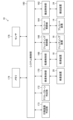
図1は実施形態に係るインクジェット印刷システムの全体構成図である。なお、同図に示す矢印線は、インクジェット印刷システム10に具備される各装置におけるフィルム基材1の搬送方向である基材搬送方向を示す。基材搬送方向はフィルム基材1が進行する方向を示す。
[Overall configuration of inkjet printing system]
1 is a diagram showing the overall configuration of an inkjet printing system according to an embodiment. The arrows in the figure indicate a substrate transport direction, which is the transport direction of a
インクジェット印刷システム10は、シングルパス方式が適用される印刷システムであり、水性カラーインクを用いて、フィルム基材1へカラー画像を印刷する。フィルム基材1は、軟包装に用いられる透明の媒体であり、非浸透媒体である。
The
フィルム基材1の例として、ONY(Oriented Nylon)、OPP(Oriented PolyPropylene)及びPET(PolyEthylene Terephthalate)などが挙げられる。インクジェット印刷システム10は、フィルム基材1に対して印刷面1Aとは反対側の基材支持面1Bから視認される裏刷りの印刷物を作成する。インクジェット印刷システム10は、印刷面1Aから視認される表刷りの印刷物の作成も可能である。
Examples of
非浸透とは、後述する水性プライマー及び水性インクに対して非浸透性を有することをいう。軟包装とは、包装される物品の形状により変形する材料による包装をいう。透明とは、可視光の透過率が30%以上100%以下であることをいい、好ましくは70%以上100%以下であることをいう。 "Non-permeable" means that the material is non-permeable to the water-based primer and water-based ink described below. "Flexible packaging" means packaging made of a material that deforms depending on the shape of the packaged item. "Transparent" means that the visible light transmittance is 30% or more and 100% or less, and preferably 70% or more and 100% or less.
インクジェット印刷システム10は、給紙装置12、プレコート装置14、ジェッティング装置16、乾燥装置18、検査装置20、回収装置22及び搬送装置24を備える。以下、各部について詳細に説明する。
The
〔給紙装置〕
インクジェット印刷システム10は、ロールトゥロール方式の搬送方式が適用される。給紙装置12は、画像が印刷される前のフィルム基材1が巻かれた送り出しロールを備える。送り出しロールは、回転自在に支持されたリールを備える。
[Paper Feeding Device]
A roll-to-roll conveying method is applied to the
給紙装置12は、フィルム基材1の印刷面1Aに対して改質処理を施すコロナ処理装置を備え得る。改質処理がされたフィルム基材1の印刷面1Aは、水性プライマーと水性インクとの水性混合物に適した表面自由エネルギーを有し、水性混合物に適した濡れ性を確保し得る。フィルム基材1は、プレコート装置14へ搬送される。
The
〔プレコート装置〕
プレコート装置14は、基材搬送方向における給紙装置12の下流側の位置であり、ジェッティング装置16の上流側の位置に配置される。プレコート装置14は、フィルム基材1の印刷面1Aへプレコート液を塗布する。
[Precoat device]
The
プレコート装置14は、プレコート乾燥装置を備え得る。プレコート乾燥装置は、フィルム基材1へ塗布されたプレコート液を乾燥させる。プレコート液は、水性プライマー液など、水性インクを不溶化又は増粘させる成分を含有する液体を適用し得る。プレコート液が塗布され、プレコート液を乾燥させたフィルム基材1はジェッティング装置16へ搬送される。プレコート乾燥装置は、後述する乾燥装置と同様の構成を適用し得る。
The
〔ジェッティング装置〕
ジェッティング装置16は、インクジェットヘッド30K、インクジェットヘッド30C、インクジェットヘッド30M、インクジェットヘッド30Y及びインクジェットヘッド30Wを備える。
[Jetting Device]
The jetting
インクジェットヘッド30K、インクジェットヘッド30C、インクジェットヘッド30M、インクジェットヘッド30Y及びインクジェットヘッド30Wのそれぞれは、ブラックインク、シアンインク、マゼンタインク、イエローインク及びホワイトインクを吐出させる。以下、インクジェットヘッド30K等を区別する必要がない場合は、インクジェットヘッド30と記載する。
インクジェットヘッド30から吐出させる水性インクは、水に対して可溶な溶媒に顔料等の色材を溶解又は分散させたインクをいう。水性インクの顔料は、有機系の顔料が用いられる。水性インクの粘度は、0.5センチポアズ以上5.0センチポアズ以下である。
The aqueous ink ejected from the
インクジェットヘッド30は、搬送装置24を用いて搬送されるフィルム基材1の印刷面1Aに対してカラーインクを吐出させ、フィルム基材1にカラー画像を印刷する。ホワイトインクは、フィルム基材1へ白色背景画像を形成する。なお、水性ホワイトインクを吐出させるインクジェットヘッド30Wを複数備えてもよい。
The
インクジェットヘッド30は、インクを吐出させるノズル面がフィルム基材1の搬送経路である基材搬送経路の基材搬送面に対向する位置及び向きとなる、配置及び姿勢が適用される。インクジェットヘッド30は、基材搬送方向に沿って等間隔に配置される。
The inkjet heads 30 are positioned and oriented so that the nozzle faces that eject ink face the substrate transport surface of the substrate transport path, which is the transport path for the
インクジェットヘッド30は複数のノズルを備える。ノズルは、ノズル開口及びインク流路が含まれ得る。インクジェットヘッド30はノズルごとにエネルギー発生素子を備える。インクジェットヘッド30のノズル面は、ノズル開口が二次元配置される。インクジェットヘッド30のノズル面は、撥水膜が形成される。
The
エネルギー発生素子は圧電素子を適用し得る。圧電素子を備えるインクジェットヘッド30は、圧電素子のたわみ変形を利用して、ノズル開口からインク液滴を吐出させる。エネルギー発生素子はヒータを適用し得る。ヒータを備えるインクジェットヘッド30は、インクの膜沸騰現象を利用して、ノズル開口からインク液滴を吐出させる。
The energy generating element may be a piezoelectric element. The
インクジェットヘッド30は、基材幅方向について、フィルム基材1の全長に渡って複数のノズルが配置されるライン型ヘッドが適用される。なお、インクジェットヘッド30は、シリアル型ヘッドを適用してもよい。
The
ライン型のインクジェットヘッド30は、基材幅方向について、複数のヘッドモジュールを繋ぎ合わせた構造を適用し得る。基材幅方向は、基材搬送方向と直交する方向であり、フィルム基材1の印刷面に平行となる方向である。
The line-
図1には四色のカラーの水性インクが適用される態様を示したが、インク色はブラック、シアン、マゼンタ及びイエローの四色に限定されない。例えば、ライトマゼンタ及びライトシアン等の淡色インクが適用される態様、グリーン、オレンジ、バイオレット、クリア及びメタリック等の特色インクが適用される態様を適用可能である。また、各色のインクジェットヘッドの配置順序も、図1に示す例に限定されない。 Although FIG. 1 shows an embodiment in which four water-based inks of different colors are applied, the ink colors are not limited to black, cyan, magenta, and yellow. For example, an embodiment in which light-colored inks such as light magenta and light cyan are applied, and an embodiment in which special color inks such as green, orange, violet, clear, and metallic are applied are also applicable. Furthermore, the arrangement order of the inkjet heads of each color is not limited to the example shown in FIG. 1.
ジェッティング装置16は、スキャナ32を備える。スキャナ32は、フィルム基材1の印刷面に印刷されたテストパターン画像を撮像し、撮像画像を電気信号に変換する撮像デバイスを備える。
The jetting
撮像デバイスの例として、CCDイメージセンサ及びカラーCMOSイメージセンサが挙げられる。なお、CCDはCharge Coupled Deviceの省略語である。また、CMOSはComplementary Metal Oxide Semiconductorの省略語である。 Examples of imaging devices include CCD image sensors and color CMOS image sensors. Note that CCD is an abbreviation for Charge Coupled Device. Also, CMOS is an abbreviation for Complementary Metal Oxide Semiconductor.
スキャナ32から出力される撮像データは、テストパターン判定部へ送信される。テストパターン判定部はテストパターンの撮像データに基づき、不良ノズルの特定等を実施する。なお、テストパターン判定部は符号172を付して図2に図示する。
The image data output from the
スキャナ32を用いてテストパターン画像が撮像されたフィルム基材1は、乾燥装置18へ搬送される。
The
〔乾燥装置〕
乾燥装置18は、基材搬送方向におけるジェッティング装置16の下流側の位置であり、基材搬送方向における検査装置20の上流側の位置に配置される。乾燥装置18は、フィルム基材1の印刷面1Aへ付着した水性インクを乾燥させる乾燥モジュールを備える。水性インクを乾燥させたフィルム基材1は、検査装置20へ搬送される。なお、乾燥装置の詳細は後述する。
[Drying equipment]
The drying
〔検査装置〕
検査装置20は、基材搬送方向における乾燥装置18の下流側の位置であり、基材搬送方向における回収装置22の上流側の位置に配置される。検査装置20は、フィルム基材1へ印刷された画像の欠陥の有無を検査する。
[Inspection equipment]
The
検査装置20は、フィルム基材1へ印刷された画像を撮像する撮像装置及びフィルム基材1へ照明光を照射する照明装置を備える。印刷画像の撮像データは印刷画像判定部へ送られる。印刷画像判定部は、印刷画像の撮像データに基づき、印刷画像の欠陥の有無を判定する。なお、印刷画像判定部は符号173を付して図2に図示する。
The
検査装置20を用いて撮像画像の検査が実施されたフィルム基材1は、回収装置22へ搬送される。
The
〔回収装置〕
回収装置22は、画像が印刷されたフィルム基材1を回収する。具体的には、画像が印刷されたフィルム基材1は、巻き取りロールへ巻き取られる。
[Recovery device]
The
〔搬送装置〕
搬送装置24は、ロールトゥロール方式が適用される。搬送装置24は、給紙装置12から回収装置22まで、給紙装置12、プレコート装置14、ジェッティング装置16、乾燥装置18、検査装置20及び回収装置22の順に、基材搬送方向について基材搬送経路に沿ってフィルム基材1を搬送する。給紙装置12及び回収装置22は、搬送装置24に含まれてもよい。
[Transportation device]
A roll-to-roll system is applied to the conveying
搬送装置24は、複数のパスローラ34を備える。パスローラ34は、給紙装置12、プレコート装置14、ジェッティング装置16、乾燥装置18、検査装置20及び回収装置22のそれぞれに、一つ以上配置される。
The conveying
搬送装置24は、給紙装置12、プレコート装置14、ジェッティング装置16、乾燥装置18、検査装置20及び回収装置22のそれぞれに一つ以上配置されるテンションピックアップ36を備える。テンションピックアップ36は、フィルム基材1へ付与されるテンションを検出する。テンションピックアップ36の検出信号は、搬送制御部へ送られる。なお、搬送制御部は符号162を用いて図2に図示する。図1では、ジェッティング装置16に具備されるテンションピックアップ36を図示し、給紙装置12等に具備されるテンションピックアップ36の図示を省略する。
The conveying
[インクジェット印刷システムの電気的構成]
図2は図1に示すインクジェット印刷システムの電気的構成を示す機能ブロック図である。インクジェット印刷システム10は、システム制御部160、搬送制御部162、プレコート制御部164、ジェッティング制御部166、乾燥制御部168、検査制御部170、テストパターン判定部172及び印刷画像判定部173を備える。
[Electrical configuration of the inkjet printing system]
Fig. 2 is a functional block diagram showing the electrical configuration of the inkjet printing system shown in Fig. 1. The
システム制御部160は、インクジェット印刷システム10の全体動作を統括的に制御する。システム制御部160は、各種の制御部へ指令信号を送信する。システム制御部160は、メモリ174へのデータの記憶及びメモリ174からのデータの読み出しを制御するメモリコントローラとして機能する。
The
システム制御部160は、センサ176から送信されるセンサ信号を取得し、センサ信号に基づく指令信号を各種の制御部へ送信する。図2に示すセンサ176は、図1に示すテンションピックアップ36が含まれる。また、センサ176はインクジェット印刷システム10の各部に具備される位置検出センサ及び温度センサ等が含まれる。
The
搬送制御部162は、システム制御部160から送信される指令信号に基づき、搬送条件を設定し、設定された搬送条件に基づき搬送装置24の動作を制御する。例えば、搬送制御部162は、搬送装置24へ適用される搬送条件を適用して、搬送装置24に具備される駆動ローラ等と連結されるモータの動作を制御する。
The
また、搬送制御部162は、インクジェット印刷システム10に具備されるプレコート装置14及びジェッティング装置16等の各セクションのそれぞれにおいて、フィルム基材1へ付与される搬送テンションを個別に制御する。すなわち、搬送制御部162は、給紙装置12から回収装置22までの各セクションにおけるフィルム基材1の搬送テンションを制御する。
The
プレコート制御部164は、システム制御部160から送信される指令信号に基づきプレコート処理の処理条件を設定し、設定された処理条件に基づきプレコート装置14の動作を制御する。
The
ジェッティング制御部166は、システム制御部160から送信される指令信号に基づき印刷条件を設定し、設定された印刷条件に基づきジェッティング装置16の動作を制御する。
The jetting
ジェッティング制御部166は、印刷データに対して、色分解処理、色変換処理、各処理の補正処理及びハーフトーン処理を実施して、印刷データに基づくハーフトーンデータを生成する画像処理部を備える。
The jetting
ジェッティング制御部166は、インクジェットヘッド30へ供給される駆動電圧を生成する駆動電圧生成部を備える。ジェッティング制御部166は、インクジェットヘッド30へ駆動電圧を供給する駆動電圧出力部を備える。
The jetting
乾燥制御部168は、システム制御部160から送信される指令信号に基づき、乾燥装置18に適用される乾燥処理の処理条件を設定し、設定された処理条件に基づき乾燥装置18の動作を制御する。
The drying
検査制御部170は、システム制御部160から送信される指令信号に基づき、検査装置20へ適用される検査条件を設定し、設定された検査条件に基づき、検査装置20の動作を制御する。
The
テストパターン判定部172は、テストパターンの撮像データを取得し、テストパターンの撮像データを解析する。テストパターン判定部172は、解析結果に基づきインクジェットヘッド30の吐出異常の有無を判定する。
The test
印刷画像判定部173は、印刷画像の撮像データを取得し、印刷画像の撮像データを解析する。印刷画像判定部173は、解析結果に基づき印刷画像における画像欠陥の有無を判定する。
The print
図3は図2に示す電気的構成のハードウェアの構成例を示すブロック図である。インクジェット印刷システム10に具備される制御装置200は、プロセッサ202、非一時的な有体物であるコンピュータ可読媒体204、通信インターフェース206及び入出力インターフェース208を備える。
Figure 3 is a block diagram showing an example of the hardware configuration of the electrical configuration shown in Figure 2. The
制御装置200は、コンピュータが適用される。コンピュータの形態は、サーバであってもよいし、パーソナルコンピュータであってもよく、ワークステーションであってもよく、また、タブレット端末などであってもよい。
The
プロセッサ202はCPU(Central Processing Unit)を含む。プロセッサ202はGPU(Graphics Processing Unit)を含んでもよい。プロセッサ202は、バス210を介してコンピュータ可読媒体204、通信インターフェース206及び入出力インターフェース208と接続される。入力装置214及びディスプレイ装置216は入出力インターフェース208を介してバス210に接続される。
The
コンピュータ可読媒体204は、主記憶装置であるメモリ及び補助記憶装置であるストレージを含む。コンピュータ可読媒体204は、半導体メモリ、ハードディスク装置及びソリッドステートドライブ装置等を適用し得る。コンピュータ可読媒体204は、複数のデバイスの任意の組み合わせを適用し得る。
The computer-
なお、ハードディスク装置は、英語表記のHard Disk Driveの省略語であるHDDと称され得る。ソリッドステートドライブ装置は、英語表記のSolid State Driveの省略語であるSSDと称され得る。 Hard disk devices can be referred to as HDD, which is an abbreviation of the English term Hard Disk Drive. Solid state drive devices can be referred to as SSD, which is an abbreviation of the English term Solid State Drive.
制御装置200は、通信インターフェース206を介してネットワークへ接続され、外部装置と通信可能に接続される。ネットワークは、LAN(Local Area Network)等を適用し得る。なお、ネットワークの図示は省略する。
The
コンピュータ可読媒体204は、搬送制御プログラム220、プレコート制御プログラム222、ジェッティング制御プログラム224、乾燥制御プログラム226、検査制御プログラム228及びテストパターン判定プログラム230が記憶される。
The computer-
搬送制御プログラム220は、図2に示す搬送装置24に適用される搬送制御に対応する。プレコート制御プログラム222は、プレコート装置14に適用されるプレコート制御に対応する。
The
ジェッティング制御プログラム224は、ジェッティング装置16に適用される印刷制御に対応する。乾燥制御プログラム226は、乾燥装置18に適用される乾燥制御に対応する。
The jetting
検査制御プログラム228は、検査装置20に適用される印刷画像の検査に対応する。テストパターン判定プログラム230は、テストパターンの撮像データに基づく吐出異常判定に適用される。
The
コンピュータ可読媒体204へ記憶される各種のプログラムは、一つ以上の命令が含まれる。コンピュータ可読媒体204は、各種のデータ及び各種のパラメータ等が記憶される。なお、図2に示すメモリ174は、図3に示すコンピュータ可読媒体204に含まれる。
The various programs stored in the computer-
インクジェット印刷システム10は、プロセッサ202がコンピュータ可読媒体204へ記憶される各種のプログラムを実行し、インクジェット印刷システム10における各種の機能を実現する。なお、プログラムという用語はソフトウェアという用語と同義である。
In the
制御装置200は、通信インターフェース206を介して外部装置とのデータ通信を実施する。通信インターフェース206は、USB(Universal Serial Bus)などの各種の規格を適用し得る。通信インターフェース206の通信形態は、有線通信及び無線通信のいずれを適用してもよい。
The
制御装置200は、入出力インターフェース208を介して、入力装置214及びディスプレイ装置216が接続される。入力装置214はキーボード及びマウス等の入力デバイスが適用される。ディスプレイ装置216は、制御装置200に適用される各種の情報が表示される。
The
ディスプレイ装置216は、液晶ディスプレイ、有機ELディスプレイ及びプロジェクタ等を適用し得る。ディスプレイ装置216は、複数のデバイスの任意の組み合わせを適用し得る。なお、有機ELディスプレイのELは、Electro-Luminescenceの省略語である。 The display device 216 may be a liquid crystal display, an organic electroluminescence display, a projector, or the like. The display device 216 may be any combination of multiple devices. Note that the EL in organic electroluminescence display is an abbreviation for Electro-Luminescence.
ここで、プロセッサ202のハードウェア的な構造例として、CPU、GPU、PLD(Programmable Logic Device)及びASIC(Application Specific Integrated Circuit)が挙げられる。CPUは、プログラムを実行して各種の機能部として作用する汎用的なプロセッサである。GPUは、画像処理に特化したプロセッサである。
Here, examples of the hardware structure of the
PLDは、デバイスを製造した後に電気回路の構成を変更可能なプロセッサである。PLDの例として、FPGA(Field Programmable Gate Array)が挙げられる。ASICは、特定の処理を実行させるために専用に設計された専用電気回路を備えるプロセッサである。 A PLD is a processor whose electrical circuitry can be reconfigured after the device is manufactured. An example of a PLD is the Field Programmable Gate Array (FPGA). An ASIC is a processor that includes dedicated electrical circuitry designed specifically to perform a specific process.
一つの処理部は、これら各種のプロセッサのうちの一つで構成されていてもよいし、同種又は異種の二つ以上のプロセッサで構成されてもよい。各種のプロセッサの組み合わせの例として、一以上のFPGAと一以上のCPUとの組み合わせ、一以上のFPGAと一以上のGPUとの組み合わせが挙げられる。各種のプロセッサの組み合わせの他の例として、一以上のCPUと一以上のGPUとの組み合わせが挙げられる。 A processing unit may be composed of one of these various processors, or may be composed of two or more processors of the same or different types. Examples of combinations of various processors include a combination of one or more FPGAs and one or more CPUs, and a combination of one or more FPGAs and one or more GPUs. Another example of a combination of various processors includes a combination of one or more CPUs and one or more GPUs.
一つのプロセッサを用いて、複数の機能部を構成してもよい。一つのプロセッサを用いて、複数の機能部を構成する例として、クライアント又はサーバ等のコンピュータに代表される、SoC(System On a Chip)などの一つ以上のCPUとソフトウェアの組合せを適用して一つのプロセッサを構成し、このプロセッサを複数の機能部として作用させる態様が挙げられる。 Multiple functional units may be configured using one processor. One example of using one processor to configure multiple functional units is to configure one processor by applying a combination of one or more CPUs and software, such as a SoC (System On a Chip), which is typified by a computer such as a client or server, and have this processor act as multiple functional units.
一つのプロセッサを用いて、複数の機能部を構成する他の例として、一つのICチップを用いて、複数の機能部を含むシステム全体の機能を実現するプロセッサを使用する態様が挙げられる。なお、ICはIntegrated Circuitの省略語である。 Another example of using one processor to configure multiple functional units is to use a processor that uses one IC chip to realize the functions of the entire system including multiple functional units. Note that IC is an abbreviation for Integrated Circuit.
このように、各種の機能部は、ハードウェア的な構造として、上記した各種のプロセッサを一つ以上用いて構成される。更に、上記した各種のプロセッサのハードウェア的な構造は、より具体的には、半導体素子等の回路素子を組み合わせた電気回路(circuitry)である。 In this way, the various functional units are configured as a hardware structure using one or more of the various processors described above. Furthermore, the hardware structure of the various processors described above is, more specifically, an electric circuit (circuitry) that combines circuit elements such as semiconductor elements.
コンピュータ可読媒体204は、ROM(Read Only Memory)及びRAM(Random Access Memory)等の半導体素子を含み得る。コンピュータ可読媒体204は、ハードディスク等の磁気記憶媒体を含み得る。コンピュータ可読媒体204は、複数の種類の記憶媒体を具備し得る。
The computer-
なお、実施形態に記載のインクジェット印刷システム10は、液体付与システムの一例である。実施形態に記載のプレコート装置14及びジェッティング装置16は液体付与装置の一例である。
The
[乾燥装置の詳細な説明]
〔第一実施形態〕
図4は第一実施形態に係る乾燥モジュールの構成例を示す正面図である。図4に示す符号Xは基材幅方向を示す。また、符号Zは鉛直上方向を示す。図5から図9に示す符号X及び符号Zについても同様である。
[Detailed Description of Drying Apparatus]
First Embodiment
Fig. 4 is a front view showing a configuration example of the drying module according to the first embodiment. The symbol X in Fig. 4 indicates the substrate width direction. The symbol Z indicates the vertically upward direction. The same applies to the symbols X and Z in Figs. 5 to 9.
乾燥モジュール1801は、ノズルユニット300及びヒータユニット320を備える。乾燥モジュール1801はノズルユニット300とは別の構成要素であるヒータユニット320において、予め規定される温度範囲の加熱気体を生成し、加熱気体をノズルユニット300へ供給する。加熱気体は空気を適用し得る。
The
ヒータユニット320は、基材搬送経路と対向しない基材搬送経路の非対向位置に配置される。また、ヒータユニット320はノズルユニット300の近接位置に配置される。これにより、加熱気体の圧力損失の低減及び加熱気体の熱損失の低減が実現される。図4に示すヒータユニット320は、ノズルユニット300の基材幅方向の一方の端301である側面306に接合される。
The
図4には、ノズルユニット300の側面306と、ヒータユニット320の基材幅方向の一方の端である気体供給口配置面327とが接合される態様を例示したが、加熱気体の流通に影響しない程度の長さを有するダクト等を介して、ノズルユニット300とヒータユニット320とが接合されてもよい。
Figure 4 illustrates an example in which the
ノズルユニット300は、複数のノズル304への加熱気体の均一供給を実現する構造を有しており、複数のノズル304への熱量の均一供給が自動的に達成される。なお、ここでいう均一は、規定の誤算範囲内のバラつきが含まれ得る。
The
ノズルユニット300は、直方体形状を有し、基材幅方向について、フィルム基材1の全長を超える長さを有する。ノズルユニット300は、基材搬送面と対向するノズル配置面302に複数のノズル304が配置される。複数のノズル304は、基材幅方向についてフィルム基材1の全長を超える長さに渡って配置される。ノズル配置面302における複数のノズル304の配置例として、二次元配置が挙げられる。複数のノズル304の二次元配置の例は、図7に図示する。
The
ノズル304は、ノズル配置面302から突出した凸形状を有し、先端にノズル開口が形成される。ノズル304はノズル開口を介して加熱された気体である加熱気体をフィルム基材1の印刷面1Aへ送風する。ノズル304に付した下向きの矢印線は、加熱気体の送風方向を示す。なお、加熱気体の送風は、加熱気体の噴射、吹き付け及び放射等と共通する概念である。
The
図4には、ノズル配置面302から突出した凸形状を有するノズル304を例示したが、ノズル304は、平らなノズル配置面302に形成される開口を適用してもよい。ノズル開口の平面形状は、円及び四角形など任意の形状が適用される。
Although FIG. 4 illustrates an example of a
ノズルユニット300は、ノズル配置面302と直交する面であり、基材搬送方向に対して平行となる側面306に、加熱気体の供給を受ける加熱気体流入口308となる貫通穴が形成される。ノズルユニット300は、加熱気体流入口308を介して、ヒータユニット320において生成された加熱気体を流入させる。
The
なお、実施形態に記載のノズル配置面302は第一面の一例である。実施形態に記載の側面306は第一面と交差する第二面の一例である。実施形態に記載のノズル304は噴射口の一例である。
The
ヒータユニット320は、ヒータ322及び軸流ファン324を備える。ヒータ322及び軸流ファン324は、加熱気体流入口308から離れる方向について、ヒータ322及び軸流ファン324の順に配置される。
The
ヒータ322は、規定の設定温度に基づき、ヒータ322の周囲の気体である空気を加熱する。ヒータ322は赤外線ヒータ等を適用し得る。軸流ファン324は、規定の送風条件に基づき、ヒータ322へ向けて送風し、加熱気体を生成する。図4に示す右向きの矢印線は軸流ファン324の送風方向を示す。
The
ヒータユニット320は、ノズルユニット300の加熱気体流入口308に対応する位置に加熱気体供給口326を備える。加熱気体供給口326はヒータ322が具備されるヒータケース323における気体供給口配置面327に形成される。加熱気体供給口326は加熱気体流入口308に対応する開口形状及び開口面積を有する。例えば、加熱気体供給口326は加熱気体流入口308と同一形状及び同一サイズを適用し得る。
The
乾燥モジュール1801は、ノズルユニット300の側面306とヒータユニット320の気体供給口配置面327とを接触させて、ノズルユニット300の加熱気体流入口308とヒータユニット320の加熱気体供給口326とを接合させる構造を有する。
The
ノズルユニット300及びヒータユニット320を含む乾燥モジュール1801は、乾燥炉330の内部に配置される。乾燥炉330は、乾燥モジュール1801を用いて乾燥処理が施されるフィルム基材1の搬送経路が含まれる。
The
かかる態様によれば、乾燥モジュール1801の全体における熱損失の削減を実現し得る。例えば、軸流ファン324の寿命等への影響を考慮して、相対的に低い加熱温度が適用される場合、乾燥モジュール1801は乾燥炉330の内部へ配置し得る。
According to this aspect, it is possible to reduce heat loss throughout the
なお、実施形態に記載の乾燥炉330は乾燥ユニットの一例である。実施形態に記載のノズルユニット300は送風ユニットの一例である。実施形態に記載のヒータユニット320は加熱気体供給ユニットの一例である。また、実施形態に記載のヒータ322は熱源の一例である。実施形態に記載の軸流ファン324はファンモータの一例である。
The drying
図5は図4に示す乾燥モジュールの変形例を示す正面図である。変形例に係る乾燥モジュール1801Aは、ノズルユニット300が乾燥炉330Aの内部に配置され、かつ、ヒータユニット320が乾燥炉330Aの外部に配置される。
Figure 5 is a front view showing a modified example of the drying module shown in Figure 4. In the modified
すなわち、乾燥炉330Aは、加熱気体流入口308に対応するサイズを有し、加熱気体流入口308に対応する配置を有する開口332が形成される。乾燥炉330Aの基材幅方向における一方の端331は、開口332と加熱気体供給口326との位置が合わせられ、ヒータユニット320が接続される。
That is, the drying
変形例に係る乾燥モジュール1801Aによれば、ヒータユニット320の交換等のメンテナンスを効率よく実施し得る。なお、実施形態に記載の乾燥炉330Aは乾燥ユニットの一例である。
The
〔第二実施形態〕
図6は第二実施形態に係る乾燥モジュールの構成例を示す平面図である。第二実施形態に係る乾燥モジュール1802は、ヒータユニット320において発生させた加熱気体をリサイクルさせる循環構造を有する。
Second Embodiment
6 is a plan view showing an example of the configuration of a drying module according to the second embodiment. A
図6に示すヒータユニット320は、乾燥炉330Aの外部に配置される。ヒータユニット320を構成するヒータ322及び軸流ファン324は、加熱気体発生ボックス360の内部へ収容される。これにより、ヒータ322が発生させた熱エネルギーを加熱気体発生ボックス360の外部へ逃がさずに、軸流ファン324は、加熱気体発生ボックス360の内部の加熱気体をノズルユニット300へ送風し得る。
The
加熱気体発生ボックス360は、外気を取り入れる第一吸気口362を備える。第一吸気口362は、加熱気体発生ボックス360を構成する任意の面に配置し得る。図6には、第一吸気口362が軸流ファン324の吸気面と対向する面に配置される態様を示す。
The heated
〔第三実施形態〕
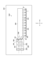
図7は第三実施形態に係る乾燥モジュールの構成例を示す底面図である。図8は図7に示す乾燥モジュールの内部構造例を示す斜視図である。図7及び図8は、乾燥モジュール1803を鉛直方向の下側から上側へ見た図である。
Third Embodiment
Fig. 7 is a bottom view showing an example of the configuration of a drying module according to a third embodiment. Fig. 8 is a perspective view showing an example of the internal structure of the drying module shown in Fig. 7. Figs. 7 and 8 are views of a
なお、図7及び図8では、ノズルユニット300が内蔵される乾燥炉の図示を省略する。また、図7及び図8に示す符号X、符号Y及び符号Zのそれぞれは、基材幅方向、乾燥モジュール1803における基材搬送方向及び鉛直上方向を示す。
Note that the drying furnace in which the
乾燥モジュール1803は、基材搬送方向におけるノズルユニット300の下流側の位置に加熱気体回収ユニット370が配置される。加熱気体回収ユニット370は、基材幅方向の一方の端面371に、加熱気体を排出させる加熱気体排出口372が形成される。なお、図8では加熱気体排出口372の図示を省略する。
In the
加熱気体回収ユニット370は、基材搬送面と対向する基材対向面374に加熱気体回収口376が形成される。加熱気体回収口376は、長方形形状の平面形状を有し、基材幅方向の長さは、ノズル304が配置される長さに対応する。
The heated
加熱気体発生ボックス360Aは、基材幅方向における他方の端面361に第二吸気口364が形成される。第二吸気口364は、加熱気体排出口372に対応する位置に配置され、加熱気体排出口372に対応する開口形状及びサイズを有する。例えば、第二吸気口364は加熱気体排出口372と同一形状及び同一サイズを適用し得る。
The heated
加熱気体回収ユニット370の一方の端面371と加熱気体発生ボックス360の他方の端面361とを接触させて接合させる際に、第二吸気口364と加熱気体排出口372との位置が合わせられる。
When one
かかる構造を有する乾燥モジュール1803は、ノズルユニット300から送風させた加熱気体が、加熱気体回収口376を介して加熱気体回収ユニット370へ回収される。加熱気体回収ユニット370へ回収された加熱気体は、加熱気体排出口372及び第二吸気口364を介して加熱気体発生ボックス360Aへ回収される。
In the
これにより、ノズルユニット300及び加熱気体回収ユニット370が内蔵される乾燥炉の内部に存在する高温の加熱気体を加熱気体発生ボックス360Aへ取り入れる熱エネルギーの循環が実現され、乾燥モジュール1803は省エネルギー効果が得られる。
This allows circulation of thermal energy by taking in the high-temperature heated gas present inside the drying furnace, which houses the
軸流ファン324は、加熱気体発生ボックス360Aからノズルユニット300及び加熱気体回収ユニット370を介して加熱気体発生ボックス360Aへ加熱気体を循環させる際の気流の発生源として機能する。
The
図7には、加熱気体回収ユニット370の形状及び構造の例として、直方体形状及び中空構造を例示する。加熱気体回収ユニット370は、基材搬送方向におけるノズルユニット300の上流側の位置に配置されていてもよい。
Figure 7 shows an example of the shape and structure of the heated
図7に示すように、加熱気体回収口376は、加熱気体回収ユニット370の長手方向である基材幅方向について三分割される。すなわち、加熱気体回収口376は第一吸気領域376A、第二吸気領域376B及び第三吸気領域376Cに分割される。
As shown in FIG. 7, the heated
加熱気体回収ユニット370は、第一吸気領域376Aと連通する第一吸気流路378A、第二吸気領域376Bと連通する第二吸気流路378B及び第三吸気領域376Cと連通する第三吸気流路378Cを備える。
The heated
すなわち、加熱気体回収ユニット370は、第一吸気流路378Aと第二吸気流路378Bとを隔てる第一隔壁379A及び第二吸気流路378Bと第三吸気領域376Cとを隔てる第二隔壁379Bを備える。
That is, the heated
加熱気体排出口372は、第一吸気流路378Aと接続される第一排気領域372A、第二吸気流路378Bと接続される第二排気領域372B及び第三吸気流路378Cと接続される第三排気領域372Cに分割される。
The heated
第一吸気領域376Aから吸引された加熱気体は、第一吸気流路378A及び第一排気領域372Aを介して加熱気体発生ボックス360Aへ回収される。また、第二吸気領域376Bから吸引された加熱気体は、第二吸気流路378B及び第二排気領域372Bを介して加熱気体発生ボックス360Aへ回収される。
The heated gas sucked in from the
更に、第三吸気領域376Cから吸引された加熱気体は、第三吸気流路378C及び第三排気領域372Cを介して加熱気体発生ボックス360Aへ回収される。軸流ファン324は、加熱気体発生ボックス360Aからノズルユニット300及び加熱気体回収ユニット370を介して加熱気体を循環させる際の気流の発生源として機能する。
Furthermore, the heated gas sucked in from the
なお、図7において、第一吸気流路378A、第二吸気流路378B及び第三吸気流路378Cに図示した矢印線は、加熱気体回収口376を介して加熱気体発生ボックス360Aへ回収される加熱気体を模式的に表す。また、図8では、複数の曲線を用いて加熱気体の流れを模式的に図示し、矢印線を用いて加熱気体の全体としての流れ方向を表す。
In addition, in FIG. 7, the arrow lines shown in the first
加熱気体回収口376を介して、加熱気体回収ユニット370へ吸気をする場合、軸流ファン324に近い側である第一吸気領域376Aの側は、軸流ファン324から遠い側である第二吸気領域376Bの側と比較して、単位期間あたりの吸引量が相対的に大きくなる傾向がある。そこで、加熱気体排出口372を複数の領域に分割し、領域ごとに加熱気体の流路である第一吸気流路378A等が具備される。
When air is drawn into the heated
これにより、加熱気体回収口376から吸気をする際に、基材幅方向における単位期間あたりの吸気量のバラつきが抑制され、同方向について均一な吸気が実現される。加熱気体回収口376及び加熱気体排出口372の分割数は、図7に示す例に限定されず任意の分割数を適用し得る。
As a result, when air is drawn in from the heated
なお、実施形態に記載の第一吸気領域376A、第二吸気領域376B及び第三吸気領域376Cのそれぞれは、加熱気体回収口の長手方向に区画された複数の吸気領域の一例である。
Note that the
また、実施形態に記載の第一排気領域372A、第二排気領域372B及び第三排気領域372Cのそれぞれは、複数の吸気領域に対応して加熱気体排出口が区画された複数の排気領域の一例である。
Furthermore, each of the
更に、実施形態に記載の第一吸気流路378A、第二吸気流路378B及び第三吸気流路378Cのそれぞれは、複数の吸気流路を構成する吸気流路の一例である。
Furthermore, each of the first
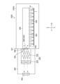
〔第四実施形態〕
図9は第四実施形態に係る乾燥モジュールの構成例を示す底面図である。第四実施形態に係る乾燥モジュール1804は、加熱気体回収ユニット370から加熱気体発生ボックス360Bへ循環させる加熱気体の単位期間あたりの体積が制御される。
Fourth Embodiment
9 is a bottom view showing an example of the configuration of a drying module according to the fourth embodiment. In the
加熱気体回収ユニット370は、ノズル304からフィルム基材1へ吹き付けた全ての加熱気体が加熱気体回収口376を介して回収される完全循環が適用される。複数の乾燥モジュール1804を備え、基材搬送方向に沿って複数の乾燥モジュール1804が配置される場合、基材搬送方向の上流側の位置に配置される乾燥モジュール1804では、同方向の下流側の位置に配置される乾燥モジュール1804と比較して、蒸発する水分量が相対的に多くなり、湿度が相対的に上昇し得る。湿度の上昇は乾燥処理の効率を低下させる懸念がある。
The heated
乾燥モジュール1804は、加熱気体発生ボックス360Bに第三吸気口380が具備される。加熱気体発生ボックス360Bは、第三吸気口380を介して乾燥モジュール1804の外部から新鮮な気体が取り入れられ、内部の湿度が調整される。
The
第三吸気口380は、開口面積を調整する開口面積調整機構382を備える。開口面積調整機構382は、シャッター及びシャッターを駆動するシャッター駆動機構を備え得る。
The
第三吸気口380は、複数の開口を備える態様を適用し得る。第三吸気口380として複数の開口を備える態様では、開口面積調整機構382は、選択的に複数の開口の一つ以上を遮蔽する遮蔽機構を適用し得る。
The
第三吸気口380は、開口面積調整機構382に代わり又は開口面積調整機構382と併用して、第三吸気口380における圧力損失調整機構が具備されてもよい。なお、圧力損失調整機構の図示を省略する。図2に示す乾燥制御部168は、開口面積調整機構382及び圧力損失調整機構等における駆動制御等を実施する。
The
乾燥モジュール1804は、温度センサ及び湿度センサの少なくともいずれかを具備し、加熱気体発生ボックス360Bの内部における温度及び湿度の少なくともいずれかを検出し、検出結果に基づき開口面積調整機構382等の動作を制御してもよい。
The
温度センサ等は、第二吸気口364の近傍の位置に配置される態様が好ましい。第二吸気口364の近傍の位置の例として、第二吸気口364が形成される端面361の内部側の面366が挙げられる。図2に示すセンサ176は、加熱気体発生ボックス360Bに具備される温度センサ等が含まれる。
The temperature sensor etc. is preferably disposed in a position near the
なお、実施形態に記載の開口面積調整機構382は、第三吸気口を通過する気体の単位期間あたりの体積を調整する調整機構の一例である。
The opening
〔第五実施形態〕
図10は第五実施形態に係る乾燥装置の構成例を示す乾燥装置の側面図である。なお、同図には、乾燥装置18に具備される乾燥炉330Aの内部構造の一例を模式的に図示する。また、同図では乾燥炉330Aの内部に配置されるノズルユニット300を図示し、乾燥炉330Aの外部に配置されるヒータユニット320の図示を省略する。同図に示す矢印線は基材搬送方向を示す。
Fifth Embodiment
Fig. 10 is a side view of a drying apparatus showing an example of the configuration of a drying apparatus according to the fifth embodiment. In addition, in the same figure, an example of the internal structure of a drying
図10に示す乾燥装置18は、乾燥炉330Aの内部においてフィルム基材1を周回させる、周回状の基材搬送経路が規定される。乾燥炉330Aの内部は、基材搬送経路に沿って複数のパスローラ34が配置される。
The drying
また、乾燥炉330Aの内部には、駆動ローラ38が配置される。基材搬送経路は、駆動ローラ38の位置で折り返される。これにより、フィルム基材1の乾燥に必要な基材搬送経路の長さが確保され、かつ、乾燥炉330Aのサイズをコンパクトにしている。
In addition, a
図10には、乾燥炉330Aの内部において、32個のノズルユニット300が分散配置される態様を例示する。なお、乾燥炉330Aの内部に配置されるノズルユニット300の数は、搬送経路の長さ及びノズルユニット300のサイズ等に応じて適宜規定し得る。
Figure 10 illustrates an example in which 32
かかる構造を有する乾燥装置18は、非浸透媒体が適用されるフィルム基材1に印刷される印刷画像であり、四色の水性カラーインクを用いて印刷されるカラー画像を、水性ホワイトインクを用いて印刷される背景画像に重畳させた印刷画像の乾燥処理を実施する。
The drying
カラー画像のみが印刷される場合と比較して、ホワイトインクを用いた背景画像が印刷される場合は、フィルム基材1へ塗布されるインク量が膨大となり、乾燥装置18における消費電力の低減化及び排気処理等の課題が存在する。
When a background image is printed using white ink, a much larger amount of ink is applied to the
図10に示す構造を有する乾燥装置18に対して、特許文献1に記載される基材の搬送経路に対してヒータを対向させる構造が適用される場合、基材搬送面に対して直交する方向について乾燥モジュール1800が大型化し、乾燥炉330Aのサイズが大型化し得る。
When a structure in which a heater faces the substrate transport path described in
これに対して、本実施形態に係る乾燥装置18は、ヒータユニット320が基材搬送面と非対向の位置に配置される。これにより、基材搬送面に対して直交する方向について乾燥炉330Aの大型化が回避される。
In contrast, in the drying
また、図10に示す乾燥モジュール1800は基材搬送方向についても乾燥モジュール1800の大型化が回避される。すなわち、乾燥モジュール1800はノズルユニット300の基材搬送方向における隣接位置へヒータユニット320が配置されず、隣り合う乾燥モジュール1804同士の距離を相対的に短くでき、基材搬送方向について乾燥炉330Aの大型化が回避される。
In addition, the
なお、図10に示す乾燥モジュール1800は、図6に示す乾燥モジュール1802、図7に示す乾燥モジュール1803及び図9に示す乾燥モジュール1804のいずれかを適用し得る。
The
図11は乾燥モジュールの他の配置例を示す乾燥装置の側面図である。なお、同図には、図10に示す乾燥炉330Aの内部における基材搬送経路の一部を図示する。同図に示す矢印線は、基材搬送方向を示す。
Figure 11 is a side view of a drying device showing another example of the arrangement of drying modules. Note that this figure also illustrates a portion of the substrate transport path inside the drying
図11に示す乾燥モジュール1800は、フィルム基材1の印刷面1Aの側の位置及び基材支持面1Bの側のそれぞれに配置される。これにより、フィルム基材1の印刷面1A及び基材支持面1Bに対して、一括して乾燥処理を実施し得る。
The
かかる態様において、フィルム基材1の印刷面1Aの側に配置される乾燥モジュール1800と、フィルム基材1の基材支持面1Bの側に配置される乾燥モジュール1800とは、ノズルユニット300とヒータユニット320との配置が入れ替えられる態様が好ましい。これにより、乾燥炉330Aの基材幅方向について同じ側にヒータユニット320を配置し得る。
In this embodiment, it is preferable that the
図12は乾燥モジュールの変形例を示す乾燥装置の側面図である。なお、図12に示す矢印線は、基材搬送方向を示す。 Figure 12 is a side view of a drying device showing a modified drying module. Note that the arrows in Figure 12 indicate the substrate transport direction.
図12に示す乾燥モジュール1805に具備されるノズルユニット3001は、第一ノズル配置面302A及び第二ノズル配置面302Bを備える。第一ノズル配置面302A及び第二ノズル配置面302Bは、複数のノズル304が配置される。
The
図12に示すノズルユニット3001は、直方体形状を有するノズルユニット3001の上面が第一ノズル配置面302Aとされ、底面が第二ノズル配置面302Bとされる。すなわち、図12に示すノズルユニット3001は、互いに平行となる二面の一方が第一ノズル配置面302Aとされ、他方の面が第二ノズル配置面302Bとされる。
The
第一ノズル配置面302Aと第二ノズル配置面302Bとは、互いに平行となる面に限定されず、互いに直交する面が適用されてもよい。互いに直交する面が適用される例として、第一ノズル配置面302Aが直方体の上面とされ、第二ノズル配置面302Bが直方体の側面とされる態様が挙げられる。
The first
かかる変形例によれば、一つのノズルユニット3001から複数の方向に向けて加熱気体を吹き付け得る。なお、ノズル配置面は二つの面に限定されず、多面体の三つ以上の面をノズル配置面としてもよい。
According to this modified example, heated gas can be sprayed in multiple directions from one
図10に戻り、基材搬送方向について複数の乾燥モジュール1800が配置される場合、基材搬送方向における上流側の領域は定率乾燥区間であり、水分蒸発量が相対的に大きく、湿度が上昇し易い。したがって、図9に示す第三吸気口380から加熱気体発生ボックス360Bの内部へ取り込まれる外気の体積が相対的に多くされる。
Returning to FIG. 10, when
一方、基材搬送方向における下流側の領域は減率乾燥区間であり、水分蒸発量が相対的に小さく、湿度が上昇し難い。したがって、第三吸気口380から加熱気体発生ボックス360Bの内部へ取り込まれる外気の体積が相対的に少なくされる。
On the other hand, the area downstream in the substrate transport direction is a falling-rate drying section, where the amount of water evaporation is relatively small and humidity is unlikely to increase. Therefore, the volume of outside air taken into the heated
すなわち、基材搬送方向における下流側に位置に配置される乾燥モジュール1800において第三吸気口380を通過する気体の単位期間あたりの体積は、基材搬送方向における上流側に位置に配置される乾燥モジュール1800において第三吸気口380を通過する気体の単位期間あたりの体積未満とされる。
In other words, the volume of gas passing through the
基材搬送方向における上流側の領域の例として、乾燥装置18におけるフィルム基材1の搬送開始位置を起点とし、起点からの距離が基材搬送経路の全長に対して15パーセント以上20パーセント以下の位置までの領域が挙げられる。
An example of an upstream region in the substrate transport direction is a region that starts from the transport start position of the
基材搬送方向における下流側の領域の例として、起点からの距離が基材搬送経路の全長に対して15パーセント以上20パーセント以下の位置から乾燥装置18におけるフィルム基材1の搬送終了位置までの領域が挙げられる。
An example of the downstream region in the substrate transport direction is the region from a position that is 15 to 20 percent of the total length of the substrate transport path from the starting point to the end position of transport of the
[実施形態に係る乾燥装置の作用効果]
実施形態に係る乾燥装置は以下の作用効果を得ることが可能である。
[Functions and Effects of the Drying Device According to the Embodiment]
The drying device according to the embodiment can provide the following advantageous effects.
〔1〕
フィルム基材1に対して加熱気体を吹き付けるノズルユニット300は、基材搬送面と対向する位置に配置される。ノズルユニット300へ加熱気体を供給するヒータユニット320は、基材搬送面と非対向の位置に配置される。これにより、基材搬送面と対向する方向における乾燥モジュールの大型化が抑制される。
[1]
The
〔2〕
乾燥モジュール1801は、乾燥炉330の内部に配置される。これにより、熱損失の低減化を実現し得る。
[2]
The
〔3〕
ノズルユニット300は乾燥炉330Aの内部に配置され、ヒータユニット320は乾燥炉330Aの外部に配置される。これにより、ヒータユニット320に具備される軸流ファン324等のメンテナンスの実施が容易となる。
[3]
The
〔4〕
ヒータユニット320は、加熱気体発生ボックス360の内部に配置される。これにより、ヒータユニット320が発生させる熱エネルギーを加熱気体発生ボックス360の外部へ逃がさずに、軸流ファン324は、加熱気体発生ボックス360の内部の加熱気体をノズルユニット300へ送風し得る。
[4]
The
〔5〕
加熱気体発生ボックス360は外気を取り込む第一吸気口362を備える。これにより、ヒータユニット320は加熱気体発生ボックス360の外気を用いて加熱気体を生成し得る。
[5]
The heated
〔6〕
ノズルユニット300から放出された加熱気体を回収する加熱気体回収ユニット370を備える。加熱気体回収ユニット370へ回収された加熱気体は、加熱気体排出口372及び第二吸気口364を介して加熱気体発生ボックス360Aへ回収される。これにより、乾燥炉330Aの内部における高温の加熱気体を加熱気体発生ボックス360Aへ回収する熱エネルギーの循環が実現され、乾燥モジュール1803は省エネルギー効果が得られる。
[6]
The
〔7〕
加熱気体回収口376は、媒体幅方向について複数の吸気領域に分割される。加熱気体回収ユニット370は、複数の吸気領域のそれぞれと接続される複数の吸気流路を備える。複数の吸気流路のそれぞれは、加熱気体排出口372が分割された複数の排気領域のそれぞれと接続される。これにより、加熱気体回収ユニット370は、基材幅方向について均一に加熱気体を吸気し得る。
[7]
The heated
〔8〕
加熱気体発生ボックス360Bは、外気を取り入れる第三吸気口380を備える。これにより、乾燥モジュール1804は、加熱気体発生ボックス360Bの内部の湿度上昇に起因する乾燥効率の低下を抑制し得る。
[8]
The heated
〔9〕
加熱気体発生ボックス360Bは、第三吸気口380の開口面積を調整する開口面積調整機構382を備える。これにより、加熱気体発生ボックス360Bは、外気の吸引体積を調整し得る。
[9]
The heated
〔10〕
加熱気体発生ボックス360Bは、第二吸気口364の近傍に温度センサ及び湿度センサの少なくともいずれかを備える。これにより、第二吸気口364を介して加熱気体発生ボックス360Bの内部へ流入する気体の温度及び湿度の少なくともいずれいかに応じて、第三吸気口380の開口面積を調整し得る。
[10]
The heated
〔11〕
基材搬送方向について、複数の乾燥モジュール1800が配置される場合、基材搬送方向の上流側の位置に配置される乾燥モジュール1800は、同方向の下流側の位置に配置される乾燥モジュール1800に対して、第三吸気口380から取り入れられる外気の体積が相対的に多くされる。これにより、乾燥装置18の全体としての乾燥効率を向上し得る。
[11]
When
〔12〕
フィルム基材1の基材支持面1Bの側に乾燥モジュール1800が配置される。これにより、フィルム基材1の基材支持面1Bの側からフィルム基材1に対して乾燥処理を実施し得る。
[12]
The
〔13〕
多面体として構成されるノズルユニット3001は、第一ノズル配置面302A及び第二ノズル配置面302B等の複数の面にノズル304が配置される。これにより、複数の方向について加熱気体の吹き付けが可能となる。
[13]
The
[ノズルユニットに適用される材料の具体例]
乾燥装置18は、フィルム基材1の材料、フィルム基材1の厚み及びフィルム基材1へ印刷される画像に応じて、乾燥処理温度が変更される。図4等に図示されるノズルユニット300は、適用される材料の厚みが相対的に厚くされる場合及び適用される材料の熱容量が相対的に大きい場合は、熱応答性の低下が懸念される。
[Specific examples of materials used for the nozzle unit]
The drying temperature of the drying
図4等に図示されるノズルユニット300は、中空構造を有する直方体形状の金属製の筐体が適用される。これにより、乾燥処理温度が変更される際のノズルユニット300における一定の熱応答性が確保され、乾燥処理温度が変更される際の待機時間を低減化し得る。
The
すなわち、ノズルユニット300に適用される材料は、一定の熱応答性を確保する観点から、熱容量がより小さい金属材料が好ましい。ノズルユニット300に適用される金属材料の例として、鉄及びステンレス等が挙げられる。
In other words, from the viewpoint of ensuring a certain level of thermal responsiveness, the material used for the
ノズルユニット300は、一種類の金属材料を用いて形成され、加工の手法として金属板の折り曲げ加工及び溶接が適用される形成が好ましい。ノズルユニット300は、ノズル配置面302に複数のノズル304が二次元状に分散して配置される観点から、一定の厚みを有し、加工性及び剛性が両立する材料の適用が好ましい。
The
ノズルユニット300は、熱容量をより小さくするという観点から筐体の容積をできる限り小さくすることがポイントとなる。一方、直方体形状のノズルユニット300において、ノズル配置面302に対して平行となる面から加熱気体が流入される場合、加熱気体流入口に対向する位置のノズル304に対して、加熱気体流入口から離れた位置のノズル304は、供給される加熱気体の単位期間あたりの体積が減少し、加熱気体の均一な送風が困難になり得る。ノズルユニット300の長手方向は、短手方向と比較して、送風分布の影響が大きい。
The key to the
加熱気体の送風分布を抑制するには、筐体の高さである、加熱気体の流入面とノズル配置面302との間の距離を相対的に大きくすればよいが、ノズルユニット300の全体の熱容量が相対的に増加してしまう。
To suppress the distribution of the heated gas, the distance between the heated gas inlet surface and the
ノズルユニット300の内部に整流板等の規制部材を配置して、加熱気体の送風分布の抑制が可能であるが、ノズルユニット300の内部構造の複雑化及びノズルユニット300の内部の流路抵抗の増加が懸念される。
It is possible to suppress the distribution of the heated gas by placing a regulating member such as a flow plate inside the
これに対して、図4等に示すように、加熱気体流入口308は、ノズル配置面302に対して直交するノズルユニット300の側面306に配置される。これにより、ノズルユニット300の高さが低く抑えられ、ノズルユニット300の長手方向について、加熱気体の送風分布が抑制される。
In response to this, as shown in FIG. 4 etc., the
図13はノズルユニットに適用される金属板の厚みの評価結果を示す表である。図13には、金属板の厚みをパラメータとして、加工性、圧力損失及び熱応答性の観点について評価をした評価結果を示す。 Figure 13 is a table showing the evaluation results of the thickness of the metal plate applied to the nozzle unit. Figure 13 shows the evaluation results in terms of workability, pressure loss, and thermal responsiveness, with the thickness of the metal plate as a parameter.
図13に示す表において、評価結果Aは最適を表す。評価結果Bは適正を表す。評価結果Cは条件付きの適正を表す。評価結果Dは不適正を表す。図14に示す表についても同様である。 In the table shown in FIG. 13, evaluation result A represents optimal. Evaluation result B represents appropriate. Evaluation result C represents conditionally appropriate. Evaluation result D represents inappropriate. The same is true for the table shown in FIG. 14.
加工性について、厚みが1.5ミリメートル未満の場合、金属板自体の剛性不足に起因して加工精度が低下し得る。したがって、加工性の観点から、金属板の厚みは1.5ミリメートル以上が好ましい。 Regarding workability, if the thickness is less than 1.5 millimeters, the processing accuracy may decrease due to insufficient rigidity of the metal plate itself. Therefore, from the viewpoint of workability, it is preferable that the thickness of the metal plate is 1.5 millimeters or more.
また、金属板の厚みが3.5ミリメートルを超える場合は、100マイクロメートル未満の直径を有するノズル304を形成する際に一定の加工精度を確保するには、加工の難易度が相対的に高くなり得る。したがって、金属板の厚みは3.5ミリメートル以下が好ましい。
In addition, if the thickness of the metal plate exceeds 3.5 millimeters, the difficulty of processing may become relatively high in order to ensure a certain level of processing accuracy when forming a
圧力損失は、ノズル304から送風される加熱気体の単位期間あたりの体積に基づき判定される。圧力損失の指標値として、ノズル304の位置から一定距離が離された位置に配置される風速計の測定値を適用し得る。金属板の厚みが相対的に大きい場合、各ノズル304における流路抵抗が相対的に増加し、ノズルユニット300の内部における圧力損失が相対的に増加する。
The pressure loss is determined based on the volume of heated gas blown from the
例えば、軸流ファン324のデューティなどの出力を一定とし、ノズル配置面302における複数の位置について風速を測定し、各位置における測定値の算術平均値を圧力損失の指標値とし得る。複数の位置の例として、ノズル配置面302の四隅及びノズル配置面の中心などを採用し得る。
For example, the output such as the duty of the
すなわち、圧力損失ついて、金属板の厚みが3.5ミリメートル以上の場合、ノズル304における流路抵抗の増加に起因する加熱気体の吹き付け圧力の低下が懸念され、一定の乾燥条件において適正とされる。一方、金属板の厚みが3.5ミリメートル未満の場合は、最適又は適正とされる。
In other words, regarding pressure loss, if the thickness of the metal plate is 3.5 millimeters or more, there is concern that the spray pressure of the heated gas will decrease due to an increase in the flow path resistance in the
熱応答性は、ヒータユニット320の温度設定を変更した場合に、ノズル304から送風される加熱気体が規定の温度に達するまでの期間に基づき判定される。金属板の厚みが相対的に厚い場合、ノズルユニット300の熱容量が相対的に増加し、熱応答性の相対的な低下が懸念される。すなわち、熱応答性ついて、厚みが3.5ミリメートル以上の場合、ノズル304における熱容量の増加に起因する熱応答性の低下が懸念され、一定の乾燥条件において適正とされる。一方、金属板の厚みが3.5ミリメートル未満の場合は、最適又は適正とされる。
The thermal responsiveness is determined based on the time it takes for the heated gas blown from the
図13に示す表における総合判断は、加工性、圧力損失及び熱応答性が、総合的に考察された評価結果を示す。厚みが1.5ミリメートル未満の場合の総合判断は不適であり、厚みが1.5ミリメートル以上2.0ミリメートル未満の場合の総合判断は最適である。 The overall judgment in the table shown in Figure 13 indicates the evaluation result in which processability, pressure loss, and thermal responsiveness are considered comprehensively. When the thickness is less than 1.5 mm, the overall judgment is inappropriate, and when the thickness is 1.5 mm or more and less than 2.0 mm, the overall judgment is optimal.
また、厚みが2.0ミリメートル以上3.5ミリメートル未満の場合の総合判断は適正であり、厚みが3.5ミリメートル以上の場合の総合判断は条件付きで適正である。 In addition, the overall judgment is appropriate when the thickness is between 2.0 millimeters and 3.5 millimeters, and is appropriate under certain conditions when the thickness is 3.5 millimeters or more.
すなわち、ノズルユニット300に適用される金属板の厚みは、1.5ミリメートル以上が好ましく、1.5ミリメートル以上3.5ミリメートル未満がより好ましい。更に好ましい金属板の厚みは、1.5ミリメートル以上2.5ミリメートル未満である。
That is, the thickness of the metal plate applied to the
[ノズルユニットに適用される構造の具体例]
ノズルユニット300は、全てのノズル304から均一に加熱気体を噴射させるには、ノズルユニット300の内部へ加熱気体を溜める必要がある。すなわち、ノズルユニット300は、全てのノズル304の開口面積の合計として算出されるノズル総面積に対して、加熱気体流入口308の開口面積が一倍以下となる構造を有する。
[Specific example of structure applied to nozzle unit]
In order for the
図14はノズルユニットに適用される構造の評価結果を示す表である。図14には、圧力損失及び風速ムラの観点について評価をした評価結果を示す。なお、図14に示す表における面積比は、ノズル総面積に対する加熱気体流入口308の開口面積の比率を表す。
Figure 14 is a table showing the evaluation results of the structure applied to the nozzle unit. Figure 14 shows the evaluation results from the viewpoints of pressure loss and wind speed unevenness. Note that the area ratio in the table shown in Figure 14 represents the ratio of the opening area of the
圧力損失は、金属板の厚み評価と同様に、ノズル304から送風される加熱気体の単位期間あたりの体積に基づき判定され、圧力損失の指標値として、ノズル304の位置から一定距離が離された位置に配置される風速計の測定値を適用し得る。ノズル304の位置から一定距離が離された位置は、基材搬送面の位置を適用し得る。
The pressure loss is determined based on the volume per unit time of the heated gas blown from the
圧力損失について、面積比が0.1未満の場合、ノズル304ごとの開口面積が相対的に小さくなり、ノズル304ごとの流路抵抗の増加に起因して圧力損失が増加し、不適である。また、面積比が0.1以上0.4未満の場合は条件付きで適正である。更に、圧力損失について、面積比が0.4以上0.7未満の場合は適正であり、面積比が0.7以上の場合は最適である。
Regarding pressure loss, when the area ratio is less than 0.1, the opening area of each
風速ムラは、全てのノズル304から送風される加熱気体が、規定範囲の風速を有しているか否かに基づき判定される。例えば、風速ムラの指標値は、ノズルユニット300の長手方向における複数の位置における風速を指標値とし得る。複数の位置は、圧力損失の指標値の導出の際に用いられた複数の位置を採用し得る。
Wind speed unevenness is determined based on whether the heated gas blown from all
風速ムラについて、面積比が0.1未満の場合は最適であり、面積比が0.1以上0.7未満の場合は適正である。また、風速ムラについて、面積比が0.7以上1.0以下の場合は、条件付きで適正である。一方、面積比が1.0を超える場合は不適正である。 Regarding wind speed unevenness, an area ratio of less than 0.1 is optimal, and an area ratio of 0.1 or more and less than 0.7 is appropriate. Also, regarding wind speed unevenness, an area ratio of 0.7 or more and 1.0 or less is conditionally appropriate. On the other hand, an area ratio of more than 1.0 is inappropriate.
図14に示す総合判断は、圧力損失及び風速ムラが、総合的に考察された評価結果を示す。面積比が0.1未満の場合及び面積比が1.0を超える場合は不適正であり、面積比が0.1以上0.4未満の場合及び面積比が0.7以上1.0以下場合は適正である。また、面積比が0.4以上0.7未満の場合は最適である。 The overall judgment shown in Figure 14 shows the evaluation result in which pressure loss and wind speed unevenness are comprehensively considered. Area ratios less than 0.1 and greater than 1.0 are inappropriate, while area ratios between 0.1 and 0.4 and between 0.7 and 1.0 are appropriate. Additionally, area ratios between 0.4 and 0.7 are optimal.
すなわち、ノズルユニット300におけるノズル総面積に対する加熱気体流入口308の開口面積の比率は、0.1以上1.0以下が好ましく、0.4以上0.7未満がより好ましい。
In other words, the ratio of the opening area of the
[用語について]
プレコート液という用語は、前処理液及び処理液などの用語と同義であり、印刷の前に塗布される液体の総称である。プレコート液は塗布液の一例である。
[Terminology]
The term "precoat liquid" is synonymous with terms such as pretreatment liquid and treatment liquid, and is a general term for a liquid that is applied before printing. The precoat liquid is an example of a coating liquid.
印刷装置という用語は、印刷機、プリンタ、印字装置、画像記録装置、画像形成装置、画像出力装置及び描画装置等の用語と同義である。画像は広義に解釈するものとし、カラー画像、白黒画像、単一色画像、グラデーション画像及び均一濃度画像等も含まれる。 The term printing device is synonymous with terms such as printing press, printer, printing device, image recording device, image forming device, image output device and drawing device. Image is to be interpreted in a broad sense, and includes color images, black and white images, single color images, gradation images and uniform density images.
印刷という用語は、画像の記録、画像の形成、印字、描画及びプリント等の用語の概念を含む。装置という用語は、システムの概念を含み得る。 The term printing includes the concepts of terms such as image recording, image formation, printing, drawing and printing. The term apparatus may include the concept of a system.
画像は、写真画像に限らず、図柄、文字、記号、線画、モザイクパターン、色の塗り分け模様及びその他の各種パターン等、並びにこれらの適宜の組み合わせを含む包括的な用語として用いる。また、画像という用語は、画像を表す画像信号及び画像データの意味を含み得る。 Image is used as a comprehensive term that includes not only photographic images but also designs, characters, symbols, line drawings, mosaic patterns, color-coded patterns, and various other patterns, as well as appropriate combinations of these. In addition, the term image can include the meaning of image signals and image data that represent an image.
以上説明した本発明の実施形態は、本発明の趣旨を逸脱しない範囲で、適宜構成要件を変更、追加、削除することが可能である。本発明は以上説明した実施形態に限定されるものではなく、本発明の技術的思想内で当該分野の通常の知識を有する者により、多くの変形が可能である。また、実施形態、変形例及び応用例は適宜組み合わせて実施してもよい。 The embodiments of the present invention described above may have their constituent elements modified, added, or deleted as appropriate without departing from the spirit of the present invention. The present invention is not limited to the embodiments described above, and many modifications may be made by a person having ordinary knowledge in the relevant field within the technical concept of the present invention. Furthermore, the embodiments, modifications, and application examples may be implemented in appropriate combinations.
1 フィルム基材
1A 印刷面
1B 基材支持面
10 インクジェット印刷システム
12 給紙装置
14 プレコート装置
16 ジェッティング装置
18 乾燥装置
20 検査装置
22 回収装置
24 搬送装置
30 インクジェットヘッド
30C インクジェットヘッド
30K インクジェットヘッド
30M インクジェットヘッド
30W インクジェットヘッド
30Y インクジェットヘッド
32 スキャナ
34 パスローラ
36 テンションピックアップ
38 駆動ローラ
160 システム制御部
162 搬送制御部
164 プレコート制御部
166 ジェッティング制御部
168 乾燥制御部
170 検査制御部
172 テストパターン判定部
173 印刷画像判定部
174 メモリ
176 センサ
200 制御装置
202 プロセッサ
204 コンピュータ可読媒体
206 通信インターフェース
208 入出力インターフェース
210 バス
214 入力装置
216 ディスプレイ装置
220 搬送制御プログラム
222 プレコート制御プログラム
224 ジェッティング制御プログラム
226 乾燥制御プログラム
228 検査制御プログラム
230 テストパターン判定プログラム
300 ノズルユニット
301 一方の端
302 ノズル配置面
302A 第一ノズル配置面
302B 第二ノズル配置面
304 ノズル
306 側面
308 加熱気体流入口
320 ヒータユニット
322 ヒータ
323 ヒータケース
324 軸流ファン
326 加熱気体供給口
327 気体供給口配置面
330 乾燥炉
330A 乾燥炉
331 端面
332 開口
360 加熱気体発生ボックス
360A 加熱気体発生ボックス
360B 加熱気体発生ボックス
361 他方の端面
362 第一吸気口
364 第二吸気口
366 面
370 加熱気体回収ユニット
371 一方の端面
372 加熱気体排出口
372A 第一排気領域
372B 第二排気領域
372C 第三排気領域
376 加熱気体回収口
376A 第一吸気領域
376B 第二吸気領域
376C 第三吸気領域
378A 第一吸気流路
378B 第二吸気流路
378C 第三吸気流路
379A 第一隔壁
379B 第二隔壁
380 第三吸気口
382 開口面積調整機構
1801 乾燥モジュール
1801A 乾燥モジュール
1802 乾燥モジュール
1803 乾燥モジュール
1804 乾燥モジュール
1805 乾燥モジュール
3001 ノズルユニット
1 Film substrate 1A Printing surface 1B Substrate support surface 10 Inkjet printing system 12 Paper feeder 14 Precoat device 16 Jetting device 18 Drying device 20 Inspection device 22 Recovery device 24 Transport device 30 Inkjet head 30C Inkjet head 30K Inkjet head 30M Inkjet head 30W Inkjet head 30Y Inkjet head 32 Scanner 34 Pass roller 36 Tension pickup 38 Drive roller 160 System control unit 162 Transport control unit 164 Precoat control unit 166 Jetting control unit 168 Drying control unit 170 Inspection control unit 172 Test pattern determination unit 173 Print image determination unit 174 Memory 176 Sensor 200 Control device 202 Processor 204 Computer readable medium 206 Communication interface 208 Input/output interface 210 Bus 214 Input device 216 Display device 220 Transport control program 222 Precoat control program 224 Jetting control program 226 Drying control program 228 Inspection control program 230 Test pattern judgment program 300 Nozzle unit 301 One end 302 Nozzle arrangement surface 302A First nozzle arrangement surface 302B Second nozzle arrangement surface 304 Nozzle 306 Side surface 308 Heated gas inlet 320 Heater unit 322 Heater 323 Heater case 324 Axial flow fan 326 Heated gas supply port 327 Gas supply port arrangement surface 330 Drying furnace 330A Drying furnace 331 End surface 332 Opening 360 Heated gas generation box 360A Heated gas generation box 360B Heated gas generation box 361 Other end surface 362 First intake port 364 Second intake port 366 Surface 370 Heated gas recovery unit 371 One end surface 372 Heated gas exhaust port 372A First exhaust area 372B Second exhaust area 372C Third exhaust area 376 Heated gas recovery port 376A First intake area 376B Second intake area 376C Third intake area 378A First intake flow path 378B Second intake flow path 378C Third intake flow path 379A First partition 379B Second partition 380 Third intake port 382 Opening area adjustment mechanism 1801 Drying module 1801A Drying module 1802 Drying module 1803 Drying module 1804 Drying module 1805 Drying module 3001 Nozzle unit
Claims (13)
前記基材搬送面と対向する第一面に噴射口が形成される送風ユニットと、
熱源及び前記熱源に対して気体を送風して前記加熱気体を発生させるファンモータが内部へ配置され、前記送風ユニットへ前記加熱気体を供給する加熱気体供給ユニットであり、前記送風ユニットから送風された前記加熱気体を取り入れる第二吸気口を備える加熱気体供給ユニットと、
前記送風ユニットから送風された加熱気体を回収する加熱気体回収口と、前記加熱気体回収口を介して回収された加熱気体を排出させる加熱気体排出口であり、前記第二吸気口と連通する加熱気体排出口と、を備える加熱気体回収ユニットと、
を備え、
前記送風ユニットは、前記第一面と交差する第二面に前記加熱気体の供給を受ける加熱気体流入口が形成され、
前記加熱気体回収口は、前記基材搬送経路における基材搬送方向と直交する基材幅方向を長手方向として、前記長手方向について区画された複数の吸気領域であり、前記長手方向に沿って配置される複数の吸気領域を備え、
前記加熱気体排出口は、前記加熱気体回収口における複数の前記吸気領域に対応して複数の排気領域に区画され、
前記加熱気体回収ユニットは、複数の前記吸気領域のそれぞれと複数の前記排気領域のそれぞれとを連通させる複数の吸気流路を備える乾燥装置。 A drying device that blows heated gas onto a substrate transport surface in a substrate transport path,
a blower unit having a first surface facing the substrate conveying surface and a blower port formed thereon;
a heated gas supply unit having a heat source and a fan motor disposed therein for blowing gas toward the heat source to generate the heated gas, the heated gas supply unit supplying the heated gas to the blower unit, the heated gas supply unit including a second intake port for taking in the heated gas blown from the blower unit;
a heated gas recovery unit including a heated gas recovery port that recovers the heated gas blown from the blowing unit, and a heated gas exhaust port that discharges the heated gas recovered via the heated gas recovery port and communicates with the second intake port;
Equipped with
The blower unit has a second surface intersecting with the first surface, and a heated gas inlet for receiving the heated gas is formed in the second surface .
the heated gas recovery port is a plurality of air intake regions partitioned in a longitudinal direction, the longitudinal direction being a substrate width direction perpendicular to a substrate transport direction in the substrate transport path, and the heated gas recovery port includes a plurality of air intake regions arranged along the longitudinal direction,
the heated gas exhaust port is partitioned into a plurality of exhaust regions corresponding to the plurality of intake regions of the heated gas recovery port,
The heated gas recovery unit is a drying apparatus including a plurality of intake passages that connect each of the plurality of intake regions to each of the plurality of exhaust regions .
前記送風ユニットに形成される前記加熱気体流入口と連通する加熱気体供給口と、
前記加熱気体供給ユニットの外気を取り込む第一吸気口と、
を備える請求項1に記載の乾燥装置。 The heating gas supply unit includes :
a heated gas supply port communicating with the heated gas inlet formed in the blower unit;
A first intake port for taking in outside air of the heated gas supply unit;
The drying device according to claim 1 .
前記第三吸気口を通過する気体の温度及び湿度の少なくともいずれかを検出するセンサと、
を備え、
前記プロセッサは、前記センサの検出結果に応じて前記調整機構の動作を制御する請求項4に記載の乾燥装置。 one or more processors;
a sensor for detecting at least one of a temperature and a humidity of a gas passing through the third air inlet;
Equipped with
The drying device according to claim 4 , wherein the processor controls an operation of the adjustment mechanism in response to a detection result of the sensor.
前記基材搬送面と対向する第一面に噴射口が形成され、前記第一面と交差する第二面に前記加熱気体の供給を受ける加熱気体流入口が形成され、前記基材搬送経路に沿って配置される複数の送風ユニットと、a plurality of blowing units arranged along the substrate transport path, the blowing units having a first surface facing the substrate transport surface and a heated gas inlet for receiving the heated gas formed on a second surface intersecting the first surface;
熱源と、A heat source;
前記熱源に対して気体を送風して前記加熱気体を発生させるファンモータと、a fan motor that blows gas toward the heat source to generate the heated gas;
前記熱源及び前記ファンモータが内部へ配置され、複数の前記送風ユニットのそれぞれに対して前記加熱気体を供給する複数の加熱気体供給ユニットであり、前記加熱気体供給ユニットの外気を取り込む第三吸気口と、前記第三吸気口を通過する気体の単位期間あたりの体積を調整する調整機構と、を備える加熱気体供給ユニットと、the heat source and the fan motor are disposed inside the heated gas supply unit, the heated gas supply unit being configured to supply the heated gas to each of the blower units, the heated gas supply unit including a third intake port that takes in outside air of the heated gas supply unit, and an adjustment mechanism that adjusts the volume of gas passing through the third intake port per unit time;
一以上のプロセッサと、one or more processors;
を備え、Equipped with
前記プロセッサは、前記調整機構の動作を制御して、基材搬送経路における基材搬送方向の下流側の位置に配置される前記加熱気体供給ユニットに具備される前記第三吸気口を通過する気体の単位期間あたりの体積を、前記基材搬送方向の上流側の位置に配置される前記加熱気体供給ユニットに具備される前記第三吸気口を通過する気体の単位期間あたりの体積未満とする乾燥装置。The processor controls the operation of the adjustment mechanism to make the volume per unit period of gas passing through the third air intake port provided in the heated gas supply unit located at a downstream position in the substrate transport direction on the substrate transport path less than the volume per unit period of gas passing through the third air intake port provided in the heated gas supply unit located at an upstream position in the substrate transport direction.
基材搬送経路における基材搬送面に対して加熱気体を送風し、前記液体が付与された基材を乾燥させる乾燥装置と、
を備え、
前記乾燥装置は、
前記基材搬送面と対向する第一面に噴射口が形成される送風ユニットと、
熱源及び前記熱源に対して気体を送風して前記加熱気体を発生させるファンモータが内部へ配置され、前記送風ユニットへ前記加熱気体を供給する加熱気体供給ユニットであり、前記送風ユニットから送風された前記加熱気体を取り入れる第二吸気口を備える加熱気体供給ユニットと、
前記送風ユニットから送風された加熱気体を回収する加熱気体回収口と、前記加熱気体回収口を介して回収された加熱気体を排出させる加熱気体排出口であり、前記第二吸気口と連通する加熱気体排出口と、を備える加熱気体回収ユニットと、
を備え、
前記送風ユニットは、前記第一面と交差する第二面に前記加熱気体の供給を受ける加熱気体流入口が形成され、
前記加熱気体回収口は、基材の搬送方向と交差する基材の幅方向を長手方向として、前記長手方向について区画された複数の吸気領域であり、前記長手方向に沿って配置される複数の吸気領域を備え、
前記加熱気体排出口は、前記加熱気体回収口における複数の前記吸気領域に対応して複数の排気領域に区画され、
前記加熱気体回収ユニットは、複数の前記吸気領域のそれぞれと複数の前記排気領域のそれぞれとを連通させる複数の吸気流路を備える液体付与システム。 A liquid application device that applies a liquid to a substrate;
a drying device that blows heated gas onto a substrate transport surface in a substrate transport path to dry the substrate to which the liquid has been applied;
Equipped with
The drying device is
a blower unit having a first surface facing the substrate conveying surface and a blower port formed thereon;
a heated gas supply unit having a heat source and a fan motor disposed therein for blowing gas toward the heat source to generate the heated gas, the heated gas supply unit supplying the heated gas to the blower unit, the heated gas supply unit including a second intake port for taking in the heated gas blown from the blower unit;
a heated gas recovery unit including a heated gas recovery port that recovers the heated gas blown from the blowing unit, and a heated gas exhaust port that discharges the heated gas recovered via the heated gas recovery port and communicates with the second intake port;
Equipped with
The blower unit has a second surface intersecting with the first surface, and a heated gas inlet for receiving the heated gas is formed in the second surface .
the heated gas recovery port is a plurality of air intake areas partitioned in a longitudinal direction, the longitudinal direction being a width direction of the substrate intersecting a transport direction of the substrate, and the heated gas recovery port includes a plurality of air intake areas arranged along the longitudinal direction,
the heated gas exhaust port is partitioned into a plurality of exhaust regions corresponding to the plurality of intake regions of the heated gas recovery port,
The heated gas recovery unit is a liquid dispensing system having a plurality of intake passages communicating with each of the plurality of intake regions and each of the plurality of exhaust regions .
複数の前記送風ユニットは、前記基材搬送経路に沿って配置される請求項8に記載の液体付与システム。 A plurality of the blower units are provided,
The liquid application system of claim 8 , wherein a plurality of the blower units are disposed along the substrate transport path.
基材搬送経路における基材搬送面に対して加熱気体を送風し、前記液体が付与された基材を乾燥させる乾燥装置と、
一以上のプロセッサと、
を備える液体付与システムであって、
前記乾燥装置は、
前記基材搬送面と対向する第一面に噴射口が形成され、前記第一面と交差する第二面に前記加熱気体の供給を受ける加熱気体流入口が形成され、前記基材搬送経路に沿って配置される複数の送風ユニットと、
熱源と、
前記熱源に対して気体を送風して前記加熱気体を発生させるファンモータと、
前記熱源及び前記ファンモータが内部へ配置され、複数の前記送風ユニットのそれぞれに対して前記加熱気体を供給する複数の加熱気体供給ユニットであり、前記加熱気体供給ユニットの外気を取り込む第三吸気口と、前記第三吸気口を通過する気体の単位期間あたりの体積を調整する調整機構と、を備える加熱気体供給ユニットと、
を備え、
前記プロセッサは、前記調整機構の動作を制御して、基材搬送経路における基材搬送方向の下流側の位置に配置される前記加熱気体供給ユニットに具備される前記第三吸気口を通過する気体の単位期間あたりの体積を、前記基材搬送方向の上流側の位置に配置される前記加熱気体供給ユニットに具備される前記第三吸気口を通過する気体の単位期間あたりの体積未満とする液体付与システム。 A liquid application device that applies a liquid to a substrate;
a drying device that blows heated gas onto a substrate transport surface in a substrate transport path to dry the substrate to which the liquid has been applied;
one or more processors;
A liquid dispensing system comprising :
The drying device includes:
a plurality of blowing units arranged along the substrate transport path, the blowing units having a first surface facing the substrate transport surface and a heated gas inlet for receiving the heated gas formed on a second surface intersecting the first surface;
A heat source;
a fan motor that blows gas toward the heat source to generate the heated gas;
the heat source and the fan motor are disposed inside the heated gas supply unit, the heated gas supply unit being configured to supply the heated gas to each of the blower units, the heated gas supply unit including a third intake port that takes in outside air of the heated gas supply unit, and an adjustment mechanism that adjusts the volume of gas passing through the third intake port per unit time;
Equipped with
The processor controls the operation of the adjustment mechanism to make the volume per unit period of gas passing through the third intake port of the heated gas supply unit located at a downstream position in the substrate transport direction on the substrate transport path less than the volume per unit period of gas passing through the third intake port of the heated gas supply unit located at an upstream position in the substrate transport direction.
基材搬送経路における基材搬送面に対して加熱気体を送風し、前記画像が印刷された基材を乾燥させる乾燥装置と、
を備え、
前記乾燥装置は、
前記基材搬送面と対向する第一面に噴射口が形成される送風ユニットと、
熱源及び前記熱源に対して気体を送風して前記加熱気体を発生させるファンモータが内部へ配置され、前記送風ユニットへ前記加熱気体を供給する加熱気体供給ユニットであり、前記送風ユニットから送風された前記加熱気体を取り入れる第二吸気口を備える加熱気体供給ユニットと、
前記送風ユニットから送風された加熱気体を回収する加熱気体回収口と、前記加熱気体回収口を介して回収された加熱気体を排出させる加熱気体排出口であり、前記第二吸気口と連通する加熱気体排出口と、を備える加熱気体回収ユニットと、
を備え、
前記送風ユニットは、前記第一面と交差する第二面に前記加熱気体の供給を受ける加熱気体流入口が形成され、
前記加熱気体回収口は、前記基材搬送経路における基材搬送方向と直交する基材幅方向を長手方向として、前記長手方向について区画された複数の吸気領域であり、前記長手方向に沿って配置される複数の吸気領域を備え、
前記加熱気体排出口は、前記加熱気体回収口における複数の前記吸気領域に対応して複数の排気領域に区画され、
前記加熱気体回収ユニットは、複数の前記吸気領域のそれぞれと複数の前記排気領域のそれぞれとを連通させる複数の吸気流路を備える印刷システム。 a printing device for printing an image onto a substrate;
a drying device that blows heated gas against a substrate transport surface in a substrate transport path to dry the substrate on which the image is printed;
Equipped with
The drying device is
a blower unit having a first surface facing the substrate conveying surface and a blower port formed thereon;
a heated gas supply unit having a heat source and a fan motor disposed therein for blowing gas toward the heat source to generate the heated gas, the heated gas supply unit supplying the heated gas to the blower unit, the heated gas supply unit including a second intake port for taking in the heated gas blown from the blower unit;
a heated gas recovery unit including a heated gas recovery port that recovers the heated gas blown from the blowing unit, and a heated gas exhaust port that discharges the heated gas recovered via the heated gas recovery port and communicates with the second intake port;
Equipped with
The blower unit has a second surface intersecting with the first surface, and a heated gas inlet for receiving the heated gas is formed in the second surface .
the heated gas recovery port is a plurality of air intake regions partitioned in a longitudinal direction, the longitudinal direction being a substrate width direction perpendicular to a substrate transport direction in the substrate transport path, and the heated gas recovery port includes a plurality of air intake regions arranged along the longitudinal direction,
the heated gas exhaust port is partitioned into a plurality of exhaust regions corresponding to the plurality of intake regions of the heated gas recovery port,
A printing system , wherein the heated gas recovery unit has a plurality of intake flow paths that communicate each of the plurality of intake regions with each of the plurality of exhaust regions .
基材搬送経路における基材搬送面に対して加熱気体を送風し、前記画像が印刷された基Heated gas is blown against the substrate conveying surface in the substrate conveying path, and the substrate on which the image is printed is
材を乾燥させる乾燥装置と、A drying device for drying the material;
一以上のプロセッサと、one or more processors;
を備える印刷システムであって、A printing system comprising:
前記乾燥装置は、The drying device is
前記基材搬送面と対向する第一面に噴射口が形成され、前記第一面と交差する第二面に前記加熱気体の供給を受ける加熱気体流入口が形成され、前記基材搬送経路に沿って配置される複数の送風ユニットと、a plurality of blowing units arranged along the substrate transport path, the blowing units having a first surface facing the substrate transport surface and a heated gas inlet for receiving the heated gas formed on a second surface intersecting the first surface;
熱源と、A heat source;
前記熱源に対して気体を送風して前記加熱気体を発生させるファンモータと、a fan motor that blows gas toward the heat source to generate the heated gas;
前記熱源及び前記ファンモータが内部へ配置され、複数の前記送風ユニットのそれぞれに対して前記加熱気体を供給する複数の加熱気体供給ユニットであり、前記加熱気体供給ユニットの外気を取り込む第三吸気口と、前記第三吸気口を通過する気体の単位期間あたりの体積を調整する調整機構と、を備える加熱気体供給ユニットと、the heat source and the fan motor are disposed inside the heated gas supply unit, the heated gas supply unit being configured to supply the heated gas to each of the blower units, the heated gas supply unit including a third intake port that takes in outside air of the heated gas supply unit, and an adjustment mechanism that adjusts the volume of gas passing through the third intake port per unit time;
を備え、Equipped with
前記プロセッサは、前記調整機構の動作を制御して、基材搬送経路における基材搬送方向の下流側の位置に配置される前記加熱気体供給ユニットに具備される前記第三吸気口を通過する気体の単位期間あたりの体積を、前記基材搬送方向の上流側の位置に配置される前記加熱気体供給ユニットに具備される前記第三吸気口を通過する気体の単位期間あたりの体積未満とする印刷システム。The processor controls the operation of the adjustment mechanism to make the volume per unit period of gas passing through the third air intake port provided in the heated gas supply unit located at a downstream position in the substrate transport direction on the substrate transport path less than the volume per unit period of gas passing through the third air intake port provided in the heated gas supply unit located at an upstream position in the substrate transport direction.
Priority Applications (4)
| Application Number | Priority Date | Filing Date | Title |
|---|---|---|---|
| JP2021103379A JP7679237B2 (en) | 2021-06-22 | 2021-06-22 | Drying device, liquid application system, and printing system |
| EP22175345.2A EP4108467B1 (en) | 2021-06-22 | 2022-05-25 | Drying device, liquid applying system, and printing system |
| US17/824,649 US12103300B2 (en) | 2021-06-22 | 2022-05-25 | Drying device, liquid applying system including drying device, and printing system including drying device |
| CN202210690690.2A CN115503357A (en) | 2021-06-22 | 2022-06-17 | Drying device, liquid applying system, and printing system |
Applications Claiming Priority (1)
| Application Number | Priority Date | Filing Date | Title |
|---|---|---|---|
| JP2021103379A JP7679237B2 (en) | 2021-06-22 | 2021-06-22 | Drying device, liquid application system, and printing system |
Publications (2)
| Publication Number | Publication Date |
|---|---|
| JP2023002247A JP2023002247A (en) | 2023-01-10 |
| JP7679237B2 true JP7679237B2 (en) | 2025-05-19 |
Family
ID=81850177
Family Applications (1)
| Application Number | Title | Priority Date | Filing Date |
|---|---|---|---|
| JP2021103379A Active JP7679237B2 (en) | 2021-06-22 | 2021-06-22 | Drying device, liquid application system, and printing system |
Country Status (4)
| Country | Link |
|---|---|
| US (1) | US12103300B2 (en) |
| EP (1) | EP4108467B1 (en) |
| JP (1) | JP7679237B2 (en) |
| CN (1) | CN115503357A (en) |
Families Citing this family (6)
| Publication number | Priority date | Publication date | Assignee | Title |
|---|---|---|---|---|
| JP2024130256A (en) * | 2023-03-14 | 2024-09-30 | キヤノン株式会社 | Drying device, recording device and control method |
| JP2024130255A (en) * | 2023-03-14 | 2024-09-30 | キヤノン株式会社 | Drying device, recording device and control method |
| JP2024173376A (en) * | 2023-06-02 | 2024-12-12 | キヤノン株式会社 | Recording apparatus and method for drying a recording apparatus |
| CN116728976B (en) * | 2023-07-31 | 2023-12-12 | 武汉国创科光电装备有限公司 | Processing system and method for small-size panel |
| JP2025042732A (en) * | 2023-09-15 | 2025-03-28 | キヤノン株式会社 | Recording device and recording method |
| JP2026034943A (en) * | 2024-08-19 | 2026-03-04 | セイコーエプソン株式会社 | Drying equipment and printing equipment |
Citations (5)
| Publication number | Priority date | Publication date | Assignee | Title |
|---|---|---|---|---|
| JP2005227388A (en) | 2004-02-10 | 2005-08-25 | Fuji Photo Film Co Ltd | Image recording device |
| JP2009285877A (en) | 2008-05-27 | 2009-12-10 | Fujifilm Corp | Inkjet recorder and recording method |
| JP2013166258A (en) | 2012-02-14 | 2013-08-29 | Dainippon Screen Mfg Co Ltd | Drying device and ink jet printing device |
| JP2018130901A (en) | 2017-02-16 | 2018-08-23 | セイコーエプソン株式会社 | Printer and printing method for the same |
| US20190381809A1 (en) | 2018-06-15 | 2019-12-19 | Hewlett-Packard Development Company, L.P. | Printing on rigid and flexible print media |
Family Cites Families (6)
| Publication number | Priority date | Publication date | Assignee | Title |
|---|---|---|---|---|
| JPS5297667U (en) * | 1976-01-21 | 1977-07-22 | ||
| JPH0815844A (en) * | 1994-06-28 | 1996-01-19 | Fuji Photo Film Co Ltd | Photosensitive material processing equipment |
| DE19956999A1 (en) * | 1998-11-27 | 2000-05-31 | Mitsubishi Paper Mills Ltd | Ink jet recording medium, method of manufacturing an ink jet printed product and ink jet printed product |
| US20050253912A1 (en) * | 2004-05-17 | 2005-11-17 | Smith David E | Humidity calibration |
| JP5453337B2 (en) | 2011-03-29 | 2014-03-26 | 京セラドキュメントソリューションズ株式会社 | Drying apparatus and ink jet recording apparatus equipped with the drying apparatus |
| JP6753695B2 (en) | 2016-05-20 | 2020-09-09 | 株式会社写真化学 | Drying unit and tablet printing equipment |
-
2021
- 2021-06-22 JP JP2021103379A patent/JP7679237B2/en active Active
-
2022
- 2022-05-25 US US17/824,649 patent/US12103300B2/en active Active
- 2022-05-25 EP EP22175345.2A patent/EP4108467B1/en active Active
- 2022-06-17 CN CN202210690690.2A patent/CN115503357A/en active Pending
Patent Citations (5)
| Publication number | Priority date | Publication date | Assignee | Title |
|---|---|---|---|---|
| JP2005227388A (en) | 2004-02-10 | 2005-08-25 | Fuji Photo Film Co Ltd | Image recording device |
| JP2009285877A (en) | 2008-05-27 | 2009-12-10 | Fujifilm Corp | Inkjet recorder and recording method |
| JP2013166258A (en) | 2012-02-14 | 2013-08-29 | Dainippon Screen Mfg Co Ltd | Drying device and ink jet printing device |
| JP2018130901A (en) | 2017-02-16 | 2018-08-23 | セイコーエプソン株式会社 | Printer and printing method for the same |
| US20190381809A1 (en) | 2018-06-15 | 2019-12-19 | Hewlett-Packard Development Company, L.P. | Printing on rigid and flexible print media |
Also Published As
| Publication number | Publication date |
|---|---|
| EP4108467B1 (en) | 2024-10-09 |
| JP2023002247A (en) | 2023-01-10 |
| US12103300B2 (en) | 2024-10-01 |
| CN115503357A (en) | 2022-12-23 |
| US20220402278A1 (en) | 2022-12-22 |
| EP4108467A1 (en) | 2022-12-28 |
Similar Documents
| Publication | Publication Date | Title |
|---|---|---|
| JP7679237B2 (en) | Drying device, liquid application system, and printing system | |
| JP2011073190A (en) | Liquid supply apparatus and image forming apparatus | |
| JP2009220499A (en) | Liquid discharge apparatus | |
| CN102189773A (en) | Image forming apparatus and drying method in image forming apparatus | |
| JP5481054B2 (en) | Inkjet recording device | |
| JP2009241316A (en) | Liquid droplet delivering device | |
| US9440459B1 (en) | System and method for treating surface of media with a digitally addressable dryer array to reduce moisture gradient and media cockle | |
| JP5085596B2 (en) | Head cleaning apparatus, image recording apparatus, and head cleaning method | |
| JP6082504B2 (en) | Drying processing apparatus, drying processing method, drying processing program, and image forming apparatus | |
| US10155400B2 (en) | Printing apparatus and printing method | |
| JP5720309B2 (en) | Liquid ejector | |
| JP7595529B2 (en) | Blower unit, drying device, liquid application system, and printing system | |
| JP7126006B2 (en) | PRINTING DEVICE, READING METHOD, AND PROGRAM | |
| US20250128521A1 (en) | Printing system, substrate state adjustment method, and program | |
| JP5276558B2 (en) | Image forming apparatus | |
| JP5187959B2 (en) | Printing device | |
| JP6267055B2 (en) | Printing apparatus and recording medium conveying apparatus | |
| US9527309B2 (en) | Liquid discharging apparatus | |
| JP2022131580A (en) | Drying device and liquid application system | |
| EP4659957A1 (en) | Printing device and printing method | |
| US11853629B1 (en) | System and method for feed forward control of printhead temperature in an inkjet printer to improve ink image quality | |
| JP2026031134A (en) | Recording device | |
| JP2024093608A (en) | Inkjet Printing Device | |
| JP2016189523A (en) | Image reading apparatus and method of setting illumination for the same, and image recording apparatus | |
| JP2011068093A (en) | Liquid feeding device and image forming device |
Legal Events
| Date | Code | Title | Description |
|---|---|---|---|
| A621 | Written request for application examination |
Free format text: JAPANESE INTERMEDIATE CODE: A621 Effective date: 20240307 |
|
| A977 | Report on retrieval |
Free format text: JAPANESE INTERMEDIATE CODE: A971007 Effective date: 20250124 |
|
| A131 | Notification of reasons for refusal |
Free format text: JAPANESE INTERMEDIATE CODE: A131 Effective date: 20250127 |
|
| A521 | Request for written amendment filed |
Free format text: JAPANESE INTERMEDIATE CODE: A523 Effective date: 20250324 |
|
| TRDD | Decision of grant or rejection written | ||
| A01 | Written decision to grant a patent or to grant a registration (utility model) |
Free format text: JAPANESE INTERMEDIATE CODE: A01 Effective date: 20250416 |
|
| A61 | First payment of annual fees (during grant procedure) |
Free format text: JAPANESE INTERMEDIATE CODE: A61 Effective date: 20250507 |
|
| R150 | Certificate of patent or registration of utility model |
Ref document number: 7679237 Country of ref document: JP Free format text: JAPANESE INTERMEDIATE CODE: R150 |