WO2018190291A1 - X-ray imaging device - Google Patents
X-ray imaging device Download PDFInfo
- Publication number
- WO2018190291A1 WO2018190291A1 PCT/JP2018/014897 JP2018014897W WO2018190291A1 WO 2018190291 A1 WO2018190291 A1 WO 2018190291A1 JP 2018014897 W JP2018014897 W JP 2018014897W WO 2018190291 A1 WO2018190291 A1 WO 2018190291A1
- Authority
- WO
- WIPO (PCT)
- Prior art keywords
- image
- period
- mode
- ray imaging
- images
- Prior art date
Links
- 238000003384 imaging method Methods 0.000 title claims abstract description 103
- 239000002131 composite material Substances 0.000 claims abstract description 129
- 238000012545 processing Methods 0.000 claims abstract description 114
- 239000000203 mixture Substances 0.000 claims abstract description 38
- 238000003786 synthesis reaction Methods 0.000 claims description 91
- 230000015572 biosynthetic process Effects 0.000 claims description 88
- 238000012937 correction Methods 0.000 claims description 35
- 238000001514 detection method Methods 0.000 claims description 27
- 230000005855 radiation Effects 0.000 claims description 10
- 230000008859 change Effects 0.000 description 29
- 239000003550 marker Substances 0.000 description 26
- 238000000034 method Methods 0.000 description 24
- 210000004204 blood vessel Anatomy 0.000 description 13
- 208000031481 Pathologic Constriction Diseases 0.000 description 7
- 230000036262 stenosis Effects 0.000 description 7
- 208000037804 stenosis Diseases 0.000 description 7
- 210000004351 coronary vessel Anatomy 0.000 description 4
- 238000002594 fluoroscopy Methods 0.000 description 4
- 230000007246 mechanism Effects 0.000 description 4
- 238000006073 displacement reaction Methods 0.000 description 3
- 230000006870 function Effects 0.000 description 3
- 230000004048 modification Effects 0.000 description 3
- 238000012986 modification Methods 0.000 description 3
- 230000008569 process Effects 0.000 description 3
- 230000002966 stenotic effect Effects 0.000 description 3
- 230000006866 deterioration Effects 0.000 description 2
- 230000002526 effect on cardiovascular system Effects 0.000 description 2
- 230000000694 effects Effects 0.000 description 2
- 239000000284 extract Substances 0.000 description 2
- 230000010354 integration Effects 0.000 description 2
- 238000002697 interventional radiology Methods 0.000 description 2
- 230000001678 irradiating effect Effects 0.000 description 2
- PXFBZOLANLWPMH-UHFFFAOYSA-N 16-Epiaffinine Natural products C1C(C2=CC=CC=C2N2)=C2C(=O)CC2C(=CC)CN(C)C1C2CO PXFBZOLANLWPMH-UHFFFAOYSA-N 0.000 description 1
- 230000005540 biological transmission Effects 0.000 description 1
- 238000010586 diagram Methods 0.000 description 1
- 230000000916 dilatatory effect Effects 0.000 description 1
- 230000010365 information processing Effects 0.000 description 1
- 239000004973 liquid crystal related substance Substances 0.000 description 1
- 239000000463 material Substances 0.000 description 1
- 239000002184 metal Substances 0.000 description 1
- 230000003287 optical effect Effects 0.000 description 1
- 230000035699 permeability Effects 0.000 description 1
- 238000006257 total synthesis reaction Methods 0.000 description 1
- 230000009466 transformation Effects 0.000 description 1
- 238000013519 translation Methods 0.000 description 1
- 230000014616 translation Effects 0.000 description 1
- 238000004846 x-ray emission Methods 0.000 description 1
Images


Classifications
-
- G06T5/73—
-
- A—HUMAN NECESSITIES
- A61—MEDICAL OR VETERINARY SCIENCE; HYGIENE
- A61B—DIAGNOSIS; SURGERY; IDENTIFICATION
- A61B6/00—Apparatus for radiation diagnosis, e.g. combined with radiation therapy equipment
- A61B6/12—Devices for detecting or locating foreign bodies
-
- A—HUMAN NECESSITIES
- A61—MEDICAL OR VETERINARY SCIENCE; HYGIENE
- A61B—DIAGNOSIS; SURGERY; IDENTIFICATION
- A61B6/00—Apparatus for radiation diagnosis, e.g. combined with radiation therapy equipment
- A61B6/46—Apparatus for radiation diagnosis, e.g. combined with radiation therapy equipment with special arrangements for interfacing with the operator or the patient
- A61B6/461—Displaying means of special interest
- A61B6/463—Displaying means of special interest characterised by displaying multiple images or images and diagnostic data on one display
-
- A—HUMAN NECESSITIES
- A61—MEDICAL OR VETERINARY SCIENCE; HYGIENE
- A61B—DIAGNOSIS; SURGERY; IDENTIFICATION
- A61B6/00—Apparatus for radiation diagnosis, e.g. combined with radiation therapy equipment
- A61B6/52—Devices using data or image processing specially adapted for radiation diagnosis
- A61B6/5205—Devices using data or image processing specially adapted for radiation diagnosis involving processing of raw data to produce diagnostic data
-
- A—HUMAN NECESSITIES
- A61—MEDICAL OR VETERINARY SCIENCE; HYGIENE
- A61B—DIAGNOSIS; SURGERY; IDENTIFICATION
- A61B6/00—Apparatus for radiation diagnosis, e.g. combined with radiation therapy equipment
- A61B6/52—Devices using data or image processing specially adapted for radiation diagnosis
- A61B6/5211—Devices using data or image processing specially adapted for radiation diagnosis involving processing of medical diagnostic data
- A61B6/5229—Devices using data or image processing specially adapted for radiation diagnosis involving processing of medical diagnostic data combining image data of a patient, e.g. combining a functional image with an anatomical image
- A61B6/5235—Devices using data or image processing specially adapted for radiation diagnosis involving processing of medical diagnostic data combining image data of a patient, e.g. combining a functional image with an anatomical image combining images from the same or different ionising radiation imaging techniques, e.g. PET and CT
-
- A—HUMAN NECESSITIES
- A61—MEDICAL OR VETERINARY SCIENCE; HYGIENE
- A61B—DIAGNOSIS; SURGERY; IDENTIFICATION
- A61B6/00—Apparatus for radiation diagnosis, e.g. combined with radiation therapy equipment
- A61B6/52—Devices using data or image processing specially adapted for radiation diagnosis
- A61B6/5258—Devices using data or image processing specially adapted for radiation diagnosis involving detection or reduction of artifacts or noise
- A61B6/5264—Devices using data or image processing specially adapted for radiation diagnosis involving detection or reduction of artifacts or noise due to motion
-
- A—HUMAN NECESSITIES
- A61—MEDICAL OR VETERINARY SCIENCE; HYGIENE
- A61B—DIAGNOSIS; SURGERY; IDENTIFICATION
- A61B6/00—Apparatus for radiation diagnosis, e.g. combined with radiation therapy equipment
- A61B6/54—Control of apparatus or devices for radiation diagnosis
-
- G—PHYSICS
- G06—COMPUTING; CALCULATING OR COUNTING
- G06T—IMAGE DATA PROCESSING OR GENERATION, IN GENERAL
- G06T11/00—2D [Two Dimensional] image generation
- G06T11/003—Reconstruction from projections, e.g. tomography
- G06T11/008—Specific post-processing after tomographic reconstruction, e.g. voxelisation, metal artifact correction
-
- G—PHYSICS
- G06—COMPUTING; CALCULATING OR COUNTING
- G06T—IMAGE DATA PROCESSING OR GENERATION, IN GENERAL
- G06T11/00—2D [Two Dimensional] image generation
- G06T11/60—Editing figures and text; Combining figures or text
-
- G06T3/14—
-
- G—PHYSICS
- G06—COMPUTING; CALCULATING OR COUNTING
- G06T—IMAGE DATA PROCESSING OR GENERATION, IN GENERAL
- G06T5/00—Image enhancement or restoration
- G06T5/50—Image enhancement or restoration by the use of more than one image, e.g. averaging, subtraction
-
- G—PHYSICS
- G06—COMPUTING; CALCULATING OR COUNTING
- G06T—IMAGE DATA PROCESSING OR GENERATION, IN GENERAL
- G06T2207/00—Indexing scheme for image analysis or image enhancement
- G06T2207/10—Image acquisition modality
- G06T2207/10116—X-ray image
-
- G—PHYSICS
- G06—COMPUTING; CALCULATING OR COUNTING
- G06T—IMAGE DATA PROCESSING OR GENERATION, IN GENERAL
- G06T2207/00—Indexing scheme for image analysis or image enhancement
- G06T2207/20—Special algorithmic details
- G06T2207/20172—Image enhancement details
- G06T2207/20201—Motion blur correction
-
- G—PHYSICS
- G06—COMPUTING; CALCULATING OR COUNTING
- G06T—IMAGE DATA PROCESSING OR GENERATION, IN GENERAL
- G06T2207/00—Indexing scheme for image analysis or image enhancement
- G06T2207/20—Special algorithmic details
- G06T2207/20212—Image combination
- G06T2207/20221—Image fusion; Image merging
-
- G—PHYSICS
- G06—COMPUTING; CALCULATING OR COUNTING
- G06T—IMAGE DATA PROCESSING OR GENERATION, IN GENERAL
- G06T2207/00—Indexing scheme for image analysis or image enhancement
- G06T2207/30—Subject of image; Context of image processing
- G06T2207/30004—Biomedical image processing
- G06T2207/30021—Catheter; Guide wire
-
- G—PHYSICS
- G06—COMPUTING; CALCULATING OR COUNTING
- G06T—IMAGE DATA PROCESSING OR GENERATION, IN GENERAL
- G06T2207/00—Indexing scheme for image analysis or image enhancement
- G06T2207/30—Subject of image; Context of image processing
- G06T2207/30004—Biomedical image processing
- G06T2207/30052—Implant; Prosthesis
Definitions
- This invention relates to an X-ray imaging apparatus.
- an X-ray imaging apparatus that generates a composite image by superimposing images based on radiation detection signals is known.
- Such an X-ray imaging apparatus is disclosed in, for example, Japanese translations of PCT publication No. 2005-510288.
- Japanese Patent Application Publication No. 2005-510288 discloses an intravascular interface using a balloon with a marker for alignment and a stent (device) attached to the balloon and less likely to absorb X-rays (radiation) than the marker.
- a medical viewing system for use in vention treatment is disclosed.
- a new image captured using X-rays is aligned with a marker of a reference image.
- a sequence image obtained by time-integrating (superimposing) the aligned images is displayed on the display means.
- the balloon to which the stent is attached is placed at a stenotic site in the blood vessel to inflate the balloon. Is placed at the stenosis site.
- intravascular intervention treatment for example, when checking the indwelling state of the stent, the procedure is performed while checking the sequence image in a state where there is almost no change in the relative position of the balloon (marker) to the stent. It may be done.
- intravascular intervention treatment for example, when a new stent is aligned with an existing stent already placed, the relative position of the balloon (marker) with respect to the stent is changed. In some cases, the procedure is performed while checking the sequence image.
- the stent is superimposed in a state where the stent is largely shifted in the sequence image, so that the stent is blurred and the visibility of the stent (device) is deteriorated.
- the present invention has been made to solve the above problems, and one object of the present invention is to suppress the display of a composite image in which the visibility of the device has deteriorated on the display unit. It is to provide a possible X-ray imaging apparatus.
- An X-ray imaging apparatus includes an image generation unit that generates an image based on a detection signal of radiation transmitted through a subject into which a device is introduced, and a plurality of images generated by the image generation unit.
- a partial period image composition mode in which images in a part of the image generation period are targeted and a composite image is generated by superimposing the images.
- the image processing unit targets the images in a part of the image generation period and generates a composite image by superimposing the images.
- the composition mode can be switched.
- the images to be superimposed are limited to images within a part of the period, so that the change in the position of the device between the images to be superimposed can be reduced.
- the image processing unit includes a full-period image synthesis mode in which the images are superimposed on each other to generate a composite image for the entire period of the image generation period.
- the image generation period is configured to be switchable to a partial period image synthesis mode in which images are superimposed on each other to generate a synthesized image.
- the composite image in which the visibility of the device is deteriorated is displayed on the display unit by switching to the partial period image synthesis mode as described above. Can be suppressed.
- the image processing unit by configuring the image processing unit to be able to switch between the full-period image synthesis mode and the partial-period image synthesis mode, it is possible to suppress the display of the synthesized image with degraded device visibility on the display unit.
- the composite image suitable for the procedure can be displayed on the display unit.
- the image processing unit is preferably configured to superimpose images for a predetermined number of frames in the partial period image synthesis mode.
- the images to be superimposed are limited to images having a predetermined number of frames within a certain period, so that the change in the position of the device between the images to be superimposed can be reliably reduced. can do.
- the X-ray imaging apparatus preferably further includes a switching input unit for the user to switch to the full-period image composition mode or the partial-period image composition mode. If configured in this way, the user can switch the mode of the image processing unit to a mode that matches the procedure, so that it is possible to reliably suppress the display of a composite image in which the visibility of the device has deteriorated on the display unit. However, a composite image suitable for the procedure can be displayed on the display unit.
- the information processing apparatus further includes a control unit that performs control to acquire information related to switching between the full-period image synthesis mode or the partial-period image synthesis mode by the switching input unit at the time of shooting start or before shooting start.
- the control unit can acquire information about the mode at the start of shooting or before the start of shooting, so in the switched mode, the image processing unit can generate a composite image from the start of shooting. Can do.
- the device can generate a sharp composite image at an early stage, so that the user can quickly perform X-ray imaging so as to stop radiation irradiation.
- the device can be operated. As a result, it is possible to effectively suppress an increase in the exposure dose of the subject.
- the device is preferably introduced into the subject separately from the first device placed in the subject and the first device, and an index for alignment is provided.
- the image processing unit includes a second device having a predetermined value so as to suppress blurring of the first device in the composite image due to relative movement of the second device with respect to the first device in the partial period image composition mode. It is configured to superimpose images having the number of frames. If comprised in this way, it can suppress that the composite image in which the visibility of the 1st device deteriorated is displayed on a display part in partial period image composition mode.
- the predetermined number of frames is the number of frames that can be sufficiently visually recognized by the second device in the composite image. If comprised in this way, the 2nd device can fully be visually recognized and the composite image by which the deterioration of the visibility of the 1st device was suppressed can be displayed on a display part.
- the number of frames of an image used for generating a composite image at the end of imaging in the full-period image synthesis mode is preferably set to generate a composite image in the partial-period image synthesis mode. More than the number of frames of the image used for. If comprised in this way, the image processing part can produce
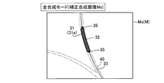
- the image processing unit preferably generates a corrected composite image by performing correction for emphasizing the device with respect to the composite image at the end of imaging in the all-period image synthesis mode.
- the display unit is configured to display a corrected composite image at the end of shooting in the all-period image composition mode. If comprised in this way, the user can recognize the state of a device more correctly by the correction
- the image processing unit is configured to superimpose all the images of the entire period of the image generation period in the all-period image synthesis mode. If comprised in this way, in a whole period image synthetic
- the image processing unit preferably superimposes the latest predetermined number of frames in the partial period image composition mode. It is configured as follows. With this configuration, in the partial period image synthesis mode, the latest synthesized image in which the device is prevented from blurring can be displayed on the display unit, so that the user can perform the procedure while checking the latest synthesized image. It can be done reliably.
- the composite image is preferably a stent-enhanced image in which a stent as a device is highlighted. If comprised in this way, it can suppress that the synthesized image in which the visibility of the stent deteriorated is displayed on a display part.
- FIG. 1 is a block diagram showing an overall configuration of an X-ray imaging apparatus according to an embodiment of the present invention. It is a figure for demonstrating the treatment tool containing a stent. It is the figure which showed an example in the case where the relative position of a stent and a marker does not change. It is a figure for demonstrating the alignment based on an area
- an X-ray imaging apparatus 100 X-rays the inside of a subject T by irradiating X-rays (radiation) from the outside of the subject T such as a human body.
- An apparatus for taking a line image An apparatus for taking a line image.
- the X-ray imaging apparatus 100 includes an X-ray irradiation unit 1, an X-ray detection unit 2, a control unit 6, a display unit 7, an operation unit 8, a storage unit 9, and an image processing device 10. Yes.
- the X-ray irradiation unit 1 irradiates the subject T into which the stent 31 (see FIG. 2) of the treatment tool 30 is introduced with X-rays.
- the X-ray detection unit 2 detects X-rays that have passed through the subject T.
- the X-ray irradiation unit 1 and the X-ray detection unit 2 are arranged so as to face each other with the top 3 on which the subject T is placed.
- the X-ray irradiation unit 1 and the X-ray detection unit 2 are supported by the moving mechanism 4 so as to be movable.
- the top plate 3 can be moved in the horizontal direction by the top plate drive unit 5.
- the moving mechanism 4 and the top board driving unit 5 are connected to the control unit 6.
- the control unit 6 can capture a predetermined region of the subject T as an image P (see FIG. 3) via the moving mechanism 4 and the top plate driving unit 5, and the X-ray irradiation unit 1, the X-ray detection unit 2, and the like.
- the top 3 is moved.
- the X-ray irradiation unit 1 includes an X-ray source 1a.
- the X-ray source 1a is an X-ray tube that is connected to a high voltage generator (not shown) and generates X-rays when a high voltage is applied.
- the X-ray source 1 a is arranged with the X-ray emission direction facing the detection surface of the X-ray detection unit 2.
- the X-ray irradiation unit 1 is connected to the control unit 6.
- the control unit 6 controls the X-ray irradiation unit 1 according to preset imaging conditions such as a tube voltage, a tube current, and an X-ray irradiation time interval, and generates X-rays from the X-ray source 1a.
- the X-ray detection unit 2 detects X-rays irradiated from the X-ray irradiation unit 1 and transmitted through the subject T, and outputs a detection signal corresponding to the detected X-ray intensity.
- the X-ray detection unit 2 is configured by, for example, FPD (Flat
- the X-ray detection unit 2 outputs an X-ray detection signal having a predetermined resolution to the image processing apparatus 10.
- the image processing apparatus 10 acquires an X-ray detection signal from the X-ray detection unit 2 and generates an image P (see FIG. 3).
- the control unit 6 is a computer including a CPU (Central Processing Unit), a ROM (Read Only Memory), a RAM (Random Access Memory), and the like.
- the control unit 6 functions as a control unit that controls each unit of the X-ray imaging apparatus 100 when the CPU executes a predetermined control program.
- the control unit 6 performs control of the X-ray irradiation unit 1 and the image processing apparatus 10 and drive control of the moving mechanism 4 and the top plate driving unit 5.
- the display unit 7 is a monitor such as a liquid crystal display, and can display the image P generated by the image processing apparatus 10.
- the control unit 6 is configured to perform control to display the image P generated by the image processing apparatus 10 on the display unit 7.
- the operation unit 8 is configured to be able to accept user input related to X-ray imaging.
- the control unit 6 is configured to accept an input operation by the user via the operation unit 8.
- the operation unit 8 also has a mode switching button 8a for switching the mode of the image processing unit 14 to be described later.
- the mode of the image processing unit 14 will be described later.
- the mode switching button 8a is an example of a “switching input unit” in the claims.
- the storage unit 9 is configured by a storage device such as a hard disk drive.
- the storage unit 9 is configured to store image data, shooting conditions, and various set values.
- Each of the display unit 7, the operation unit 8, and the storage unit 9 may be provided in the image processing apparatus 10.
- the X-ray imaging apparatus 100 is configured to be able to acquire the image P by two kinds of methods of X-ray fluoroscopy and X-ray imaging.
- the radiation dose of the subject T can be reduced by irradiating the subject T with a smaller amount of radiation than in X-ray imaging, while a low-quality image P is acquired.
- an image P with a certain high image quality is acquired.
- the image processing apparatus 10 image processing is performed in real time while the image P is captured.
- the image processing apparatus 10 is a computer including a processor 11 such as a CPU or a GPU (Graphics Processing Unit) and a storage unit 12 such as a ROM and a RAM. That is, the image processing apparatus 10 is configured by causing the processor 11 to execute the image processing program 15 stored in the storage unit 12.
- the image processing apparatus 10 may be configured integrally with the control unit 6 by causing the same hardware (CPU) as the control unit 6 to execute the image processing program.
- the storage unit 12 stores an image processing program 15 for causing a computer to function as the image processing apparatus 10.
- the storage unit 12 is configured to temporarily accumulate an image P, a composite image M, and the like generated by an image generation unit 13 described later as image data 16.
- the image processing apparatus 10 includes an image generation unit 13 and an image processing unit 14 as functions by executing the image processing program 15.
- the image generation unit 13 and the image processing unit 14 may be individually configured by dedicated processors.
- the image generation unit 13 is configured to generate an image P based on an X-ray detection signal transmitted through the subject T into which the stent 31 (see FIG. 2) of the treatment tool 30 has been introduced.
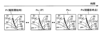
- the image generation unit 13 generates the image P in the form of a moving image based on the detection signal of the X-ray detection unit 2. That is, X-rays are intermittently emitted from the X-ray irradiation unit 1 to the subject T at predetermined time intervals, and X-rays transmitted through the subject T are sequentially detected by the X-ray detection unit 2.
- the image generation unit 13 generates the image P at a frame rate of 15 FPS by imaging the detection signals sequentially output from the X-ray detection unit 2.
- the frame rate may be about 7.5 FPS to 30 FPS.
- the image P is, for example, an image having a pixel value of a predetermined number of gradations (such as 10 to 12 bits) in gray scale. Therefore, a pixel with a low pixel value is displayed with a small luminance value in black (dark), and a pixel with a high pixel value is displayed with a large luminance value in white (bright). Note that the image may be reversed in black and white.
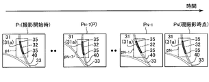
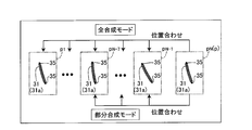
- the image processing unit 14 performs image processing for creating a composite image M (see FIGS. 6 to 8) by superimposing a plurality of images P (see FIG. 3) continuously generated by the image generation unit 13. It is configured to be possible. Specifically, the image processing unit 14 first extracts a region p including a pair of markers 35 from a plurality of images P for alignment as shown in FIG. Then, as shown in FIG. 4, the image processing unit 14 uses the affine transformation or the like so that the position of the pair of markers 35 in each region p is in the region p N of the image P N at the current photographing time (latest). Two-dimensional alignment is performed so as to coincide with the positions of the pair of markers 35. Then, as illustrated in FIG.
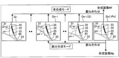
- the image processing unit 14 generates the position-corrected image Q after alignment by aligning the image P using the aligned region p. Finally, the image processing unit 14 superimposes the position correction image Q (performs time integration), thereby combining (accumulating) the stent 31 as a stent-enhanced image in which the stent 31 is highlighted as shown in FIGS. ) Generate an image M.
- the image processing unit 14 is configured to generate the composite image M every time an image P is newly generated by the image generation unit 13. As a result, the generated composite image M can be displayed on the display unit 7 as a moving image in real time.
- the image processing unit 14 superimposes a plurality of images P generated by the image generation unit 13 to create a composite image M, which is either a full synthesis mode or a partial synthesis mode. It is configured to be switchable.
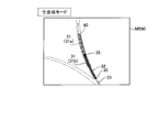
- the image processing unit 14 superimposes all the images P (P 1 to P N , see FIG. 3) in the entire image generation period to superimpose a composite image M (Mf (Ms), FIG. 7) is a mode for generating).
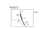
- the image processing unit 14 superimposes the latest (most recent) 8-frame image P (P N-7 to P N , see FIG. 6), which is a partial period of the image generation period.
- a composite image M (Mp, see FIG. 8) is generated.
- the partial synthesis mode when an image of 8 frames is not obtained, a synthesized image M similar to that in the full synthesis mode is generated.
- the “image generation period” means a period during which a plurality of images are generated by the image generation unit 13, and specifically means a period from the start of shooting to the current shooting time.
- the full synthesis mode and the partial synthesis mode are examples of the “full-period image synthesis mode” and the “partial-period image synthesis mode” in the claims, respectively.
- control unit 6 is configured to acquire information relating to mode switching based on the operation content to the mode switching button 8a when the user operates the mode switching button 8a.
- the control unit 6 is configured to acquire information related to mode switching in advance before shooting starts. Then, the control unit 6 is configured to switch the mode of the image processing unit 14 to either the full synthesis mode or the partial synthesis mode by transmitting information regarding mode switching to the image processing unit 14. .
- the X-ray imaging apparatus 100 of the present embodiment can be used for coronary intervention treatment.
- the coronary intervention treatment is a treatment for dilating the stenosis of the blood vessel 40 (see FIG. 3) in the coronary artery of the heart.
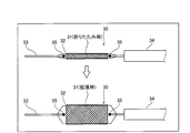
- a treatment tool 30 including a stent 31 is used.
- the treatment device 30 includes a stent 31, a balloon 32 to which the stent 31 is attached, a guide wire 33 to which the stent 31 and the balloon 32 are attached in the vicinity of the distal end, and a catheter 34 in which the guide wire 33 is accommodated.
- the stent 31 has a cylindrical shape having a network structure formed of a thin metal or the like, and is easy to transmit X-rays and is difficult to appear in the image P.
- the balloon 32 to which the stent 31 is attached is provided with a pair of markers 35 made of a material having low X-ray permeability (or non-transmission) as a mark.
- the pair of markers 35 is provided in the vicinity of both ends of the stent 31 so as to sandwich the stent 31.
- the stent 31 is configured to expand from a folded state when the balloon 32 is inflated.
- the stent 31 is an example of the “device” in the claims.
- the doctor refers to the catheter 34 with the blood vessel of the subject T while referring to a low-quality real-time moving image (image) by fluoroscopy displayed on the display unit 7.
- a procedure is performed in which the catheter 34 is inserted into the stenosis portion of the blood vessel 40 in the coronary artery of the heart through the blood vessel 40.
- the doctor positions the stent 31 (31a) and the balloon 32 at the stenosis site while referring to the real-time moving image of the composite image M or the still image of the composite image M obtained by X-ray imaging displayed on the display unit 7. .
- the doctor expands the stenotic region of the blood vessel 40 by inflating the balloon 32 and expands the folded stent 31a so as to place it in the blood vessel 40.
- the blood vessel 40 is supported from the inside by the stent 31a.
- the doctor confirms whether the stent 31a is correctly placed while referring to a real-time moving image of the composite image M or a still image of the composite image M obtained by X-ray photography.
- the doctor performs a procedure for adjusting the stent 31a by, for example, inflating the balloon 32 again.
- the relative positions of the stent 31a and the pair of markers 35 of the balloon 32 hardly change.
- the image processing unit 14 When the mode is switched to the full synthesis mode, the image processing unit 14 first sets a pair of images P (images P 1 to P N ) for alignment, as shown in FIG. A region p (regions p 1 to p N ) including the marker 35 is taken out. Then, as shown in FIG. 4, the image processing unit 14 aligns the areas p 1 to p N. Thereafter, the image processing unit 14 aligns the images P 1 to P N-1 using the aligned regions p 1 to p N-1 as shown in FIG. Corrected images Q 1 to Q N-1 are generated. Finally, the image processing unit 14 generates the composite image Mf shown in FIG. 6 by superimposing the position correction images Q 1 to Q N (Q N is equal to P N ) (perform time integration). .
- the stent 31a since the relative position between the stent 31a and the marker 35 does not change, the position of the pair of markers 35 in each of the regions p 1 to p N-1 matches the position of the pair of markers 35 in the region p N.
- the stent 31a becomes substantially the same position in the position correction image Q i (1 ⁇ i ⁇ N ⁇ 1) and the position correction image Q N.
- the composite image Mf in which the position correction image Q (image P) is superimposed the stent 31a is emphasized and displayed on the display unit 7 because there is almost no displacement of the stent 31a in the position correction images Q 1 to Q N. Is done.
- the composite image Mf is continuously generated and displayed on the display unit 7 as a real-time moving image.
- the number of images P (the number of frames) used to generate the composite image Mf increases as time elapses from the start of shooting, so the composite image displayed on the display unit 7 as a real-time moving image.
- the stent 31a gradually becomes clear and the image quality is improved.
- the image processing unit 14 emphasizes the stent 31a with respect to the composite image Mf generated last. Correction processing is performed.
- this correction processing for example, since the stent 31a has a linear shape unlike the blood vessel 40, the image processing unit 14 performs processing such as increasing the contrast of the linear portion. Thereby, the image processing unit 14 generates a corrected composite image Ms with higher image quality in which the stent 31a is more emphasized from the composite image Mf. As shown in FIG. 8, the corrected composite image Ms is displayed on the display unit 7 as a still image. As a result, the doctor can surely confirm whether the stent 31a is correctly placed.
- the user can confirm in real time that a sufficiently high-quality composite image Mf has been obtained and end the X-ray imaging. Therefore, the X-ray imaging ends with the composite image M having an insufficient image quality. Can be suppressed.
- the user can confirm in real time that a sufficiently high-quality composite image Mf has been obtained and can quickly finish X-ray imaging, it is possible to effectively increase the exposure amount of the subject T. It is possible to suppress.
- the image processing unit 14 first, as shown in FIG. 3, for the alignment, the latest (most recent) 8 frames among the plurality of images P.
- a region p (regions p N-7 to p N ) including the pair of markers 35 is extracted from the image P (images P N-7 to P N ).
- the image processing unit 14 aligns the areas p N-7 to p N.
- the image processing unit 14 aligns the images P N-7 to P N-1 using the aligned regions p N-7 to p N-1, thereby Position-corrected images Q N-7 to Q N-1 after the alignment are generated.
- the image processing unit 14 generates a composite image Mp shown in FIG. 8 by superimposing the position correction images Q N-7 to Q N.
- the stent 31a since the relative position between the stent 31a and the marker 35 does not change, in the position correction image Q i (N ⁇ 7 ⁇ i ⁇ N ⁇ 1) and the position correction image Q N in the same manner as in the full synthesis mode, the stent 31a becomes substantially the same position. As a result, as shown in FIG. 7, in the composite image Mp in which the position correction image Q (image P) is superimposed, the stent 31a is hardly displaced in the position correction images Q N-7 to Q N. Is highlighted and displayed on the display unit 7. The composite image Mp is continuously generated and displayed on the display unit 7 as a real-time moving image.
- the number of images P (number of frames) used to generate the composite image Mp does not change at 8 frames even when time has elapsed from the start of shooting. For this reason, in the synthesized image Mp displayed as a real-time moving image, the sharpness of the stent 31a hardly changes.
- a new stent 31b (31 separate from the stent 31a placed in the blood vessel 40 is used. Is performed to reach the stenotic site of the blood vessel 40 of the coronary artery of the heart. Then, in order to reliably support the blood vessel 40 at the stenosis site from the inside by the pair of stents 31a and 31b, the doctor refers to the real-time moving image of the composite image M obtained by X-ray imaging, and already has the indwelling stent 31a. Then, the positioning procedure of the new stent 31b and the balloon 32 is performed.
- the stents 31a and 31b are examples of the “first device” and the “second device” in the claims, respectively.
- the existing stent 31a is not attached to the balloon 32. Therefore, as shown in FIG. 9, the relative position between the new stent 31b and the pair of markers 35 of the balloon 32 does not change, while the existing stent 31a and the pair of markers 35 of the balloon 32 move relative to each other. That is, the relative position between the existing stent 31a and the marker 35 changes.
- the image processing unit 14 When the mode is switched to the all-combination mode, as in the case described above, the image processing unit 14 first selects a pair from all of the plurality of images P (images P 1 to P N ) as shown in FIG. A region p (regions p 1 to p N ) including the marker 35 is extracted. Then, the image processing unit 14 aligns the regions p 1 to p N as shown in FIG. Thereafter, the image processing unit 14 generates position corrected images Q 1 to Q N-1 using the regions p 1 to p N-1 as shown in FIG. Finally, the image processing unit 14 generates a composite image Mf shown in FIG. 12 by superimposing the position correction images Q 1 to Q N.
- the position of the pair of markers 35 in each of the regions p 1 to p N-1 is the pair of markers in the region p N.
- the stent 31b is substantially in the same position in the position correction image Q i (1 ⁇ i ⁇ N ⁇ 1) and the position correction image Q N.
- the stent 31b is highlighted and displayed in the composite image Mf in which the position correction image Q (image P) is superimposed.
- the existing stent 31a is positioned at different positions in the position correction image Q i and the position correction image Q N (for example, Q 1 and Q N in FIG. 11). Therefore, as shown in FIG. 12, in the composite image Mf in which the position correction image Q (image P) is overlaid, the stent 31a is blurred due to the large displacement of the stent 31a in the position correction images Q 1 to Q N. It is displayed on the display unit 7.
- the image processing unit 14 first, as shown in FIG. A region p (region p N-7 to p N ) including the pair of markers 35 is taken out from P (images P N-7 to P N ). The image processing unit 14 then aligns the regions p N-7 to p N as shown in FIG. Thereafter, as shown in FIG. 11, the image processing unit 14 generates position-corrected images Q N-7 to Q N-1 using the regions p N-7 to p N-1 . Finally, the image processing unit 14 generates a composite image Mp shown in FIG. 13 by superimposing the position correction images Q N-7 to Q N.
- the relative position between the stent 31a and the marker 35 changes, the change in the relative position between the stent 31a and the marker 35 is small in the latest (most recent) eight frames (about 0.5 seconds).
- the position correction image Q In i (N ⁇ 7 ⁇ i ⁇ N ⁇ 1) and the position correction image Q N are in substantially the same position.
- the number of frames is eight, so that the number of frames where the stent 31b can be sufficiently visually confirmed is secured.
- the user when the user performs a procedure in which the relative position between the stent 31 and the marker 35 is changed, the user switches the mode of the image processing unit 14 to the partial synthesis mode.
- the composite image Mp in which the stent 31 is sufficiently emphasized without blurring can be displayed on the display unit 7 during X-ray imaging.
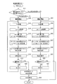
- step S11 the control unit 6 determines whether or not the mode has been switched to the partial synthesis mode. If the control unit 6 determines that the mode is switched to the partial synthesis mode, the process proceeds to step S23, and X-ray imaging is performed in steps S23 to S31 while the mode is switched to the partial synthesis mode.
- step S 12 When the control unit 6 determines that the mode is not switched to the partial synthesis mode, in steps S12 to S22, X-ray imaging is performed in a state where the mode is switched to the full synthesis mode.
- step S ⁇ b> 12 X-ray imaging is started by transmitting, to the control unit 6, information related to an input operation related to imaging start performed by the user on the operation unit 8.
- step S ⁇ b> 13 the control unit 6 causes the X-ray detection unit 2 to detect X-rays transmitted through the subject T by causing the X-ray irradiation unit 1 to emit X-rays, and outputs a detection signal. Then, the image generating unit 13 generates an image P N on the basis of the detection signal.
- step S14 the image processing unit 14 extracts regions p 1 to p N from the images P 1 to P N-1 generated before the image P N and the newly generated image P N , respectively. get.
- step S15 the image processing unit 14 performs alignment of regions p 1 ⁇ p N-1 on the basis of the area p N.
- step S16 the image processing unit 14 aligns the images P 1 to P N-1 based on the alignment results of the regions p 1 to p N-1 , thereby correcting the position corrected images Q 1 to Q N. Generate N-1 .
- step S17 the image processing unit 14 generates a composite image Mf by superimposing the position correction images Q 1 to Q N.
- step S ⁇ b> 18 the composite image Mf generated by the image processing unit 14 is displayed on the display unit 7 via the control unit 6.
- step S21 the image processing unit 14 performs correction by correcting the latest composite image Mf so that the stent 31 is emphasized.
- a composite image Ms is generated.
- step S ⁇ b> 22 the corrected composite image Ms generated by the image processing unit 14 is displayed on the display unit 7 via the control unit 6. Thereafter, the control flow is terminated.
- step S11 If it is determined in step S11 that the control unit 6 has been switched to the partial synthesis mode, X-ray imaging is started in step S23 as in step S12. Then, in step S24, similarly to step S12, the image generation unit 13 generates an image P N on the basis of the detection signal.
- step S25 the image processing unit 14, among the image P 1 ⁇ P N-1 which is generated before the image P N, the image P N-7 ⁇ P N- 1 and the new latest (most recent) Regions p N ⁇ 7 to p N are obtained from the image P N generated in (1). Then, in step S26, the image processing unit 14, to position the region p N-7 ⁇ p N- 1 on the basis of the area p N. Thereafter, in step S27, the image processing unit 14 aligns the images P N-7 to P N-1 based on the alignment results of the regions p N-7 to p N-1 , thereby correcting the position corrected image. Q N-7 to Q N-1 are generated.
- step S28 the image processing unit 14 generates a composite image Mp by superimposing the position correction images Q N-7 to Q N. Thereafter, in step S ⁇ b> 29, the composite image Mp generated by the image processing unit 14 is displayed on the display unit 7 via the control unit 6.
- step S30 the control unit 6 determines whether or not X-ray imaging has been completed, as in step S19.
- N is incremented, the flow returns to step S24, the image generation unit 13 generates a new image P N.
- the control flow is finished.
- the image processing unit 14 is set to the partial synthesis mode in which the image P is superimposed on the image P in a part of the image generation period to generate the composite image M (Mp).
- Configure to be switchable the image P to be superimposed is limited to the image P within a part of the period (nearest), so the position of the stent 31a between the images P to be superimposed (a pair of markers of the stent 31a and the balloon 32) (Relative position with respect to 35) can be reduced.
- the image processing unit 14 targets the image P in the entire period of the image generation period as an object, superimposes the images P and generates the composite image Mf, and a part of the image generation period.
- the image P in the period it is configured to be switchable to a partial synthesis mode in which the images P are superimposed to generate a composite image Mp.
- the display unit 7 is prevented from displaying the composite image Mp whose visibility of the stent 31 has deteriorated by switching to the partial composite mode. can do.
- the image processing unit 14 configuring the image processing unit 14 to be switchable between the full synthesis mode and the partial synthesis mode, the display unit 7 is prevented from displaying the composite image M in which the visibility of the stent 31 has deteriorated.
- the composite image M suitable for the procedure can be displayed on the display unit 7.
- the image processing unit 14 is configured to superimpose the images P on the image P having a predetermined number of frames (8 frames) in a partial period of the image generation period in the partial synthesis mode. To do.
- the image P to be superimposed is limited to the image P having a predetermined number of frames (8 frames) within a part of the period, so that the change in the position of the stent 31a between the images P to be superimposed is ensured. Can be made smaller.
- it is possible to further suppress the stent 31a from being overlapped in a shifted state it is possible to further suppress blurring of the stent 31 in the composite image Mp in which the image P is superimposed.
- the X-ray imaging apparatus 100 includes a mode switching button 8a for the user to switch to the full synthesis mode or the partial synthesis mode.
- a mode switching button 8a for the user to switch to the full synthesis mode or the partial synthesis mode.
- the X-ray imaging apparatus 100 includes the control unit 6 that performs control to acquire information related to switching between the full synthesis mode or the partial synthesis mode by the mode switching button 8a before the start of imaging.
- the control part 6 can acquire the information regarding a mode before a photography start
- the composite image M can be made to produce
- the stent 31 can generate a sharp composite image M at an early stage, and thus the X-ray imaging apparatus 100 is configured to stop radiation irradiation at an early stage. Can be operated. Therefore, it is possible to effectively suppress an increase in the exposure amount of the subject T.
- the image processing unit 14 has a predetermined number of frames (8) so as to suppress blurring of the stent 31a in the composite image due to relative movement of the stent 31b with respect to the stent 31a in the partial composite mode. Frames) are superposed. Thereby, in partial synthetic mode, it can control that synthetic picture Mp which visibility of stent 31a deteriorated is displayed on indicator 7.
- the predetermined number of frames (8 frames) in the partial synthesis mode is the number of frames in which the stent 31b is sufficiently visible in the synthesized image M.
- the number of frames of the image P used to generate the composite image Mf at the end of shooting in the total composition mode is equal to the number of frames of the image P used to generate the composite image Mp in the partial composition mode ( More than 8 frames).
- the image processing unit 14 can reliably generate the composite image Mf in which the stent 31 is clear at the end of photographing in the all-composite mode.
- the image processing unit 14 is configured to generate the corrected composite image Ms by performing correction that emphasizes the stent 31 on the composite image Mf at the end of photographing in the full composite mode.
- the display unit 7 is configured to display the corrected composite image Ms at the end of shooting in the full composite mode.
- the image processing unit 14 is configured to superimpose all the images P in the entire image generation period in the all composition mode. Thereby, the stent 31 can generate a clear composite image Mf at an earlier stage in the full synthesis mode.
- the image processing unit 14 is configured to superimpose the images P on the image P having the latest predetermined number of frames (eight frames) in the partial synthesis mode.
- the latest synthesized image Mp in which the blur of the stent 31 is suppressed can be displayed on the display unit 7, so that the user can reliably perform the procedure while checking the latest synthesized image Mp. It can be carried out.
- the composite image M is a stent-enhanced image in which the stent 31 is highlighted. Thereby, it can suppress that the synthesized image M in which the visibility of the stent 31 deteriorated is displayed on the display unit 7.
- an example of the X-ray imaging apparatus 100 used for coronary (cardiovascular) interventional treatment is shown, but the present invention is not limited to this.
- the present invention may be applied to an X-ray imaging apparatus used for purposes other than coronary intervention treatment.
- the present invention capable of suppressing the display of a composite image whose visibility has deteriorated due to a change in the relative position of the device with respect to an index (marker) is a blood vessel that may cause a change in the position of the device It can also be used as an X-ray imaging apparatus used for internal IVR (interventional radiology) treatment.
- the total synthesis mode is a mode in which all the images P (P 1 to P N ) in the entire period of the image generation period are overlapped to generate the composite image M (Mf).
- the present invention is not limited to this.
- the all period image composition mode only a part of the images in the entire period of the image generation period may be used.
- an image in which no marker can be detected may be excluded from the images to be superimposed among the images in the entire period of the image generation period.
- images may be extracted every several frames from images of all periods arranged in time series, and excluded from images to be superposed with images other than the plurality of extracted images.
- the X-ray imaging apparatus may be configured so that the whole-period composition mode to be used can be selected.
- the partial synthesis mode (partial period image synthesis mode) generates the composite image M (Mp) by superimposing the images P (P N-7 to P N ) of a part of the image generation period.
- this invention is not limited to this. In the present invention, even in the partial period image synthesis mode, only a part of the images in a part of the image generation period may be used. For example, in the partial period image synthesis mode, an image in which a marker cannot be detected among images in a part of the image generation period may be excluded from the superimposed image.
- image alignment may be performed without using a marker.
- a plurality of feature points in the image for example, a portion of the subject that absorbs radiation more easily than other portions
- the images are aligned so that the plurality of feature points match between the images. You may go.
- the partial synthesis mode can be employed in order to suppress the generation of a composite image in which the stent is blurred due to the feature point moving relative to the stent.
- the device may be a balloon without a stent attached. Even in this case, for example, when positioning is performed between an existing stent and a balloon having a marker, generation of a composite image in which the stent is blurred due to a change in the position of the stent is suppressed. Therefore, it is possible to adopt the partial synthesis mode.
- the present invention is not limited to this.
- the number of frames in the partial period image composition mode is not limited to 8 frames, and may be less than 8 frames or more than 8 frames.
- the number of frames is preferably changed according to the frame rate. For example, if the frame rate is 30 FPS, for example, 15 frames of images greater than 8 frames may be superimposed, and if the frame rate is 7.5 FPS, for example, 4 frames of images less than 8 frames may be combined. You may superimpose.
- the number of frames of the image to be superimposed in the partial period image composition mode is preferably the number of frames corresponding to about 0.3 seconds to 1 second and 4 frames or more. It is not limited to.
- the image processing unit 14 may generate a composite image by superimposing images of a predetermined number of frames in some period other than the latest period.
- the image processing unit may superimpose a predetermined number of frames in the first half or middle of the image generation period in the partial period image synthesis mode.
- control unit 6 acquires information related to mode switching in advance before shooting starts, but the present invention is not limited to this.
- the control unit may be configured to acquire information related to mode switching at the start of shooting.
- the X-ray imaging apparatus may be configured to start imaging in the switched mode based on the switching operation of the switching input unit by the user. Further, the X-ray imaging apparatus may be configured so that the mode of the image processing unit can be switched during X-ray imaging.
- the mode of the image processing unit 14 is switched to either the full synthesis mode or the partial synthesis mode when the user operates the mode switching button 8a.
- the mode of the image processing unit may be switched based on a switching instruction from a user other than the mode switching button.
- the mode of the image processing unit may be switched based on the user's voice, or the mode of the image processing unit is switched based on the user's movement (for example, the user's movement that blocks the light of the optical sensor). May be.
- the X-ray imaging apparatus may automatically switch the mode of the image processing unit without being based on a user switching instruction.
- image recognition may be performed on the first image captured at the start of imaging, and the X-ray imaging apparatus may automatically switch the mode of the image processing unit based on the result of image recognition. For example, when a plurality of stents are recognized in the first image taken at the start of imaging, the X-ray imaging apparatus automatically switches the mode of the image processing unit to the partial synthesis mode, and a plurality of stents are not recognized.
- the X-ray imaging apparatus may be configured to switch to the full synthesis mode.
- the mode of the image processing unit 14 is switchable during X-ray imaging, but the present invention is not limited to this.
- the mode of the image processing unit may be switchable during fluoroscopy.
- Control part 7 Display part 8a Mode switching button (switching input part) 13 Image generator 14 Image processor 31 Stent (device) 31a Stent (device, first device) 31b Stent (device, second device) 100 X-ray imaging apparatus M, Mf, Mp Composite image Ms Corrected composite image P Image T Subject
Abstract
An image processing unit (13) of this X-ray imaging device is configured so as to be capable of switching between an entire-period image composition mode in which images are layered to create a composite image (M) using images from an entire image creation period, and a partial-period image composition mode in which images are layered to create a composite image using images from part of the image creation period.
Description
この発明は、X線撮影装置に関する。
This invention relates to an X-ray imaging apparatus.
従来、放射線の検出信号に基づく画像を重ね合わせて合成画像を生成するX線撮影装置が知られている。このようなX線撮影装置は、たとえば、特表2005-510288号公報に開示されている。
Conventionally, an X-ray imaging apparatus that generates a composite image by superimposing images based on radiation detection signals is known. Such an X-ray imaging apparatus is disclosed in, for example, Japanese translations of PCT publication No. 2005-510288.
特表2005-510288号公報には、位置合わせのためのマーカーが付されたバルーンと、バルーンに取り付けられ、マーカーよりもX線(放射線)を吸収しにくいステント(デバイス)とを用いる血管内インターベンション治療に使用される医用ビューイングシステムが開示されている。特表2005-510288号公報に記載の医用ビューイングシステムでは、X線を用いて撮影された新規の画像を、参照画像のマーカーに対して位置合わせを行う。そして、位置合わせを行った画像同士を時間積分した(重ね合わせた)シーケンス画像を表示手段に表示するように構成されている。
Japanese Patent Application Publication No. 2005-510288 discloses an intravascular interface using a balloon with a marker for alignment and a stent (device) attached to the balloon and less likely to absorb X-rays (radiation) than the marker. A medical viewing system for use in vention treatment is disclosed. In the medical viewing system described in JP 2005-510288 A, a new image captured using X-rays is aligned with a marker of a reference image. A sequence image obtained by time-integrating (superimposing) the aligned images is displayed on the display means.
なお、特表2005-510288号公報に記載の医用ビューイングシステムを用いた血管内インターベンション治療では、ステントが取り付けられたバルーンを血管内の狭窄部位に配置してバルーンを膨張させることにより、ステントを狭窄部位に配置する。ここで、血管内インターベンション治療では、たとえば、ステントの留置状態を確認する場合などのように、ステントに対するバルーン(マーカー)の相対位置の変化がほとんどない状態で、シーケンス画像を確認しながら手技が行われる場合がある。また、血管内インターベンション治療では、たとえば、新たなステントを既に留置された既設のステントに対して位置合わせをする場合などのように、ステントに対するバルーン(マーカー)の相対位置の変化がある状態で、シーケンス画像を確認しながら手技が行われる場合とがある。
In the intravascular interventional treatment using the medical viewing system described in JP-T-2005-510288, the balloon to which the stent is attached is placed at a stenotic site in the blood vessel to inflate the balloon. Is placed at the stenosis site. Here, in intravascular intervention treatment, for example, when checking the indwelling state of the stent, the procedure is performed while checking the sequence image in a state where there is almost no change in the relative position of the balloon (marker) to the stent. It may be done. In intravascular intervention treatment, for example, when a new stent is aligned with an existing stent already placed, the relative position of the balloon (marker) with respect to the stent is changed. In some cases, the procedure is performed while checking the sequence image.
しかしながら、特表2005-510288号公報に記載された医用ビューイングシステムでは、ステントに対するバルーン(マーカー)の相対位置の変化がある状態で、シーケンス画像を確認しながら手技が行われる際に、シーケンス画像においてステントがぼやけてしまい、シーケンス画像(合成画像)においてステント(デバイス)の視認性が悪化するという問題点がある。具体的には、たとえば、撮影された時間が大きく異なることに起因してステントの位置の変化が大きい画像同士を重ね合わせる場合、位置合わせを行った後の画像において、ステントの位置が大きくずれる。このため、画像を重ね合わせてシーケンス画像を生成した場合に、シーケンス画像においてステントが大きくずれた状態で重ね合わせられるので、ステントがぼやけてしまい、ステント(デバイス)の視認性が悪化する。
However, in the medical viewing system described in JP 2005-510288 A, when a procedure is performed while checking the sequence image in a state where the relative position of the balloon (marker) with respect to the stent is changed, the sequence image is displayed. In this case, the stent is blurred, and the visibility of the stent (device) is deteriorated in the sequence image (composite image). Specifically, for example, when images having a large change in the position of the stent due to significantly different photographing times are overlapped, the position of the stent is greatly shifted in the image after the alignment. For this reason, when the sequence image is generated by superimposing the images, the stent is superimposed in a state where the stent is largely shifted in the sequence image, so that the stent is blurred and the visibility of the stent (device) is deteriorated.
この発明は、上記のような課題を解決するためになされたものであり、この発明の1つの目的は、デバイスの視認性が悪化した合成画像が表示部に表示されるのを抑制することが可能なX線撮影装置を提供することである。
The present invention has been made to solve the above problems, and one object of the present invention is to suppress the display of a composite image in which the visibility of the device has deteriorated on the display unit. It is to provide a possible X-ray imaging apparatus.
この発明の一の局面によるX線撮影装置は、デバイスが導入された被検体を透過した放射線の検出信号に基づく画像を生成する画像生成部と、画像生成部により生成される複数の画像を重ね合わせる画像処理部と、画像を表示可能な表示部と、を備え、画像処理部は、画像生成期間の全期間の画像を対象として、画像を重ね合わせて合成画像を生成する全期間画像合成モードと、画像生成期間の一部の期間の画像を対象として、画像を重ね合わせて合成画像を生成する部分期間画像合成モードとに切替可能に構成されている。
An X-ray imaging apparatus according to an aspect of the present invention includes an image generation unit that generates an image based on a detection signal of radiation transmitted through a subject into which a device is introduced, and a plurality of images generated by the image generation unit. An image processing unit for combining, and a display unit capable of displaying an image, wherein the image processing unit targets all the images in the entire image generation period and generates a composite image by superimposing the images. And a partial period image composition mode in which images in a part of the image generation period are targeted and a composite image is generated by superimposing the images.
この発明の一の局面によるX線撮影装置では、上記のように、画像処理部は、画像生成期間の一部の期間の画像を対象として、画像を重ね合わせて合成画像を生成する部分期間画像合成モードに切替可能に構成されている。これにより、部分期間画像合成モードにおいて、重ね合わせる画像が一部の期間内の画像に限定されるので、重ね合わせる画像間におけるデバイスの位置の変化を小さくすることができる。この結果、デバイスがずれた状態で重ね合わせられるのを抑制することができるので、画像が重ね合わされた合成画像において、デバイスがぼやけるのを抑制することができる。したがって、デバイスの視認性が悪化した合成画像が表示部に表示されるのを抑制することができる。
In the X-ray imaging apparatus according to one aspect of the present invention, as described above, the image processing unit targets the images in a part of the image generation period and generates a composite image by superimposing the images. The composition mode can be switched. Thereby, in the partial period image composition mode, the images to be superimposed are limited to images within a part of the period, so that the change in the position of the device between the images to be superimposed can be reduced. As a result, it is possible to suppress overlapping of the devices in a shifted state, and thus it is possible to suppress blurring of the devices in the composite image in which the images are superimposed. Therefore, it is possible to suppress the composite image in which the visibility of the device is deteriorated from being displayed on the display unit.
また、一の局面によるX線撮影装置では、上記のように、画像処理部は、画像生成期間の全期間の画像を対象として、画像を重ね合わせて合成画像を生成する全期間画像合成モードと、画像生成期間の一部の期間の画像を対象として、画像を重ね合わせて合成画像を生成する部分期間画像合成モードとに切替可能に構成されている。これにより、画像生成期間の全期間に亘ってデバイスの位置の変化がほとんどない状態で手技を行う場合には、全期間画像合成モードに切り替えられることによって、位置の変化がほとんどないデバイスが確実に重ね合わされるので、デバイスが鮮明な高画質の合成画像を表示部に表示させることができる。一方で、画像生成期間においてデバイスの位置の変化が大きい場合には、部分期間画像合成モードに切り替えられることによって、上記のように、デバイスの視認性が悪化した合成画像が表示部に表示されるのを抑制することができる。これらの結果、画像処理部を全期間画像合成モードと部分期間画像合成モードとに切替可能に構成することによって、デバイスの視認性が悪化した合成画像が表示部に表示されるのを抑制しつつ、手技に適した合成画像を表示部に表示させることができる。
Further, in the X-ray imaging apparatus according to one aspect, as described above, the image processing unit includes a full-period image synthesis mode in which the images are superimposed on each other to generate a composite image for the entire period of the image generation period. The image generation period is configured to be switchable to a partial period image synthesis mode in which images are superimposed on each other to generate a synthesized image. As a result, when performing a procedure with almost no change in the position of the device over the entire period of the image generation period, it is possible to ensure that a device with little change in the position is obtained by switching to the image synthesis mode for the entire period. Since the images are superimposed, the device can display a clear high-quality composite image on the display unit. On the other hand, when the change in the position of the device is large during the image generation period, the composite image in which the visibility of the device is deteriorated is displayed on the display unit by switching to the partial period image synthesis mode as described above. Can be suppressed. As a result, by configuring the image processing unit to be able to switch between the full-period image synthesis mode and the partial-period image synthesis mode, it is possible to suppress the display of the synthesized image with degraded device visibility on the display unit. The composite image suitable for the procedure can be displayed on the display unit.
上記一の局面によるX線撮影装置において、好ましくは、画像処理部は、部分期間画像合成モードにおいて、所定のフレーム数の画像を対象として、画像を重ね合わせるように構成されている。このように構成すれば、部分期間画像合成モードにおいて、重ね合わせる画像が一部の期間内の所定のフレーム数の画像に限定されるので、重ね合わせる画像間におけるデバイスの位置の変化を確実に小さくすることができる。これにより、デバイスがずれた状態で重ね合わせられるのをより抑制することができるので、画像が重ね合わされた合成画像において、デバイスがぼやけるのをより抑制することができる。
In the X-ray imaging apparatus according to the above aspect, the image processing unit is preferably configured to superimpose images for a predetermined number of frames in the partial period image synthesis mode. With this configuration, in the partial period image composition mode, the images to be superimposed are limited to images having a predetermined number of frames within a certain period, so that the change in the position of the device between the images to be superimposed can be reliably reduced. can do. As a result, it is possible to further suppress overlapping of the devices in a shifted state, and thus it is possible to further suppress the device from being blurred in the composite image in which the images are superimposed.
上記一の局面によるX線撮影装置において、好ましくは、ユーザが全期間画像合成モードまたは部分期間画像合成モードに切り替えるための切替入力部をさらに備える。このように構成すれば、画像処理部のモードを、手技に合わせたモードにユーザが切り替えることができるので、確実に、デバイスの視認性が悪化した合成画像が表示部に表示されるのを抑制しつつ、手技に適した合成画像を表示部に表示させることができる。
The X-ray imaging apparatus according to the above aspect preferably further includes a switching input unit for the user to switch to the full-period image composition mode or the partial-period image composition mode. If configured in this way, the user can switch the mode of the image processing unit to a mode that matches the procedure, so that it is possible to reliably suppress the display of a composite image in which the visibility of the device has deteriorated on the display unit. However, a composite image suitable for the procedure can be displayed on the display unit.
この場合、好ましくは、切替入力部による全期間画像合成モードまたは部分期間画像合成モードの切替に関する情報を、撮影開始時または撮影開始の前に取得する制御を行う制御部をさらに備える。このように構成すれば、制御部に撮影開始時または撮影開始の前にモードに関する情報を取得させることができるので、切り替えられたモードで、撮影開始時から画像処理部に合成画像を生成させることができる。これにより、たとえば、全期間画像合成モードに切り替えられている状態においては、早期にデバイスが鮮明な合成画像を生成させることができるので、ユーザは早期に放射線の照射を停止するようにX線撮影装置を操作することができる。この結果、被検体の被ばく量が増加するのを効果的に抑制することができる。
In this case, it is preferable that the information processing apparatus further includes a control unit that performs control to acquire information related to switching between the full-period image synthesis mode or the partial-period image synthesis mode by the switching input unit at the time of shooting start or before shooting start. With this configuration, the control unit can acquire information about the mode at the start of shooting or before the start of shooting, so in the switched mode, the image processing unit can generate a composite image from the start of shooting. Can do. Thereby, for example, in a state where the mode is switched to the image synthesis mode for the entire period, the device can generate a sharp composite image at an early stage, so that the user can quickly perform X-ray imaging so as to stop radiation irradiation. The device can be operated. As a result, it is possible to effectively suppress an increase in the exposure dose of the subject.
上記一の局面によるX線撮影装置において、好ましくは、デバイスは、被検体内に留置された第1デバイスと、第1デバイスとは別個に被検体内に導入され、位置合わせのための指標を有する第2デバイスとを含み、画像処理部は、部分期間画像合成モードにおいて、第1デバイスに対する第2デバイスの相対移動に起因して合成画像において第1デバイスがぼやけるのを抑制するように、所定のフレーム数の画像を重ね合わせるように構成させている。このように構成すれば、部分期間画像合成モードにおいて、第1デバイスの視認性が悪化した合成画像が表示部に表示されるのを抑制することができる。
In the X-ray imaging apparatus according to the above aspect, the device is preferably introduced into the subject separately from the first device placed in the subject and the first device, and an index for alignment is provided. The image processing unit includes a second device having a predetermined value so as to suppress blurring of the first device in the composite image due to relative movement of the second device with respect to the first device in the partial period image composition mode. It is configured to superimpose images having the number of frames. If comprised in this way, it can suppress that the composite image in which the visibility of the 1st device deteriorated is displayed on a display part in partial period image composition mode.
この場合、好ましくは、所定のフレーム数は、合成画像において、第2デバイスが十分に視認可能なフレーム数である。このように構成すれば、第2デバイスを十分に視認可能で、かつ、第1デバイスの視認性の悪化が抑制された合成画像を表示部に表示させることができる。
In this case, preferably, the predetermined number of frames is the number of frames that can be sufficiently visually recognized by the second device in the composite image. If comprised in this way, the 2nd device can fully be visually recognized and the composite image by which the deterioration of the visibility of the 1st device was suppressed can be displayed on a display part.
上記一の局面によるX線撮影装置において、好ましくは、全期間画像合成モードにおいて撮影終了時の合成画像を生成するために用いる画像のフレーム数は、部分期間画像合成モードにおいて合成画像を生成するために用いる画像のフレーム数よりも多い。このように構成すれば、画像処理部は、全期間画像合成モードの撮影終了時において、デバイスが鮮明な合成画像を確実に生成することができる。
In the X-ray imaging apparatus according to the above aspect, the number of frames of an image used for generating a composite image at the end of imaging in the full-period image synthesis mode is preferably set to generate a composite image in the partial-period image synthesis mode. More than the number of frames of the image used for. If comprised in this way, the image processing part can produce | generate a composite image with a clear device at the time of completion | finish of imaging | photography of all period image composition mode.
上記一の局面によるX線撮影装置において、好ましくは、画像処理部は、全期間画像合成モードでの撮影終了時の合成画像に対してデバイスを強調する補正を行うことにより補正合成画像を生成するように構成されており、表示部は、全期間画像合成モードでの撮影終了時に、補正合成画像を表示するように構成されている。このように構成すれば、ユーザは、全期間画像合成モードでの撮影終了後に表示部に表示される補正合成画像によって、デバイスの状態をより正確に認識することができる。
In the X-ray imaging apparatus according to the above aspect, the image processing unit preferably generates a corrected composite image by performing correction for emphasizing the device with respect to the composite image at the end of imaging in the all-period image synthesis mode. The display unit is configured to display a corrected composite image at the end of shooting in the all-period image composition mode. If comprised in this way, the user can recognize the state of a device more correctly by the correction | amendment synthetic | combination image displayed on a display part after completion | finish of imaging | photography in all period image synthetic | combination mode.
上記一の局面によるX線撮影装置において、好ましくは、画像処理部は、全期間画像合成モードにおいて、画像生成期間の全期間の画像の全てを重ね合わせるように構成されている。このように構成すれば、全期間画像合成モードにおいて、より早期にデバイスが鮮明な合成画像を生成させることができる。
In the X-ray imaging apparatus according to the above aspect, preferably, the image processing unit is configured to superimpose all the images of the entire period of the image generation period in the all-period image synthesis mode. If comprised in this way, in a whole period image synthetic | combination mode, a device can produce | generate a clear synthetic | combination image earlier.
上記部分期間画像合成モードにおいて、所定のフレーム数の画像を対象として画像を重ね合わせる構成において、好ましくは、画像処理部は、部分期間画像合成モードにおいて、最新の所定のフレーム数の画像を重ね合わせるように構成されている。このように構成すれば、部分期間画像合成モードにおいて、デバイスがぼやけるのが抑制された最新の合成画像を表示部に表示させることができるので、ユーザは、最新の合成画像を確認しながら手技を確実に行うことができる。
In the above-described partial period image composition mode, in the configuration in which the images are overlapped for a predetermined number of frames, the image processing unit preferably superimposes the latest predetermined number of frames in the partial period image composition mode. It is configured as follows. With this configuration, in the partial period image synthesis mode, the latest synthesized image in which the device is prevented from blurring can be displayed on the display unit, so that the user can perform the procedure while checking the latest synthesized image. It can be done reliably.
上記一の局面によるX線撮影装置において、好ましくは、合成画像は、デバイスとしてのステントが強調表示されたステント強調画像である。このように構成すれば、ステントの視認性が悪化した合成画像が表示部に表示されるのを抑制することができる。
In the X-ray imaging apparatus according to the above aspect, the composite image is preferably a stent-enhanced image in which a stent as a device is highlighted. If comprised in this way, it can suppress that the synthesized image in which the visibility of the stent deteriorated is displayed on a display part.
本発明によれば、上記のように、デバイスの視認性が悪化した合成画像が表示部に表示されるのを抑制することができる。
According to the present invention, as described above, it is possible to suppress the composite image in which the visibility of the device has deteriorated from being displayed on the display unit.
以下、本発明を具体化した実施形態を図面に基づいて説明する。
Hereinafter, an embodiment of the present invention will be described with reference to the drawings.
(X線撮影装置の構成)
図1~図8を参照して、本発明の一実施形態によるX線撮影装置100の構成について説明する。 (Configuration of X-ray imaging apparatus)
A configuration of anX-ray imaging apparatus 100 according to an embodiment of the present invention will be described with reference to FIGS.
図1~図8を参照して、本発明の一実施形態によるX線撮影装置100の構成について説明する。 (Configuration of X-ray imaging apparatus)
A configuration of an
本発明の一実施形態によるX線撮影装置100は、図1に示すように、人体などの被検体Tの外側からX線(放射線)を照射することによって、被検体T内を画像化したX線画像を撮影する装置である。
As shown in FIG. 1, an X-ray imaging apparatus 100 according to an embodiment of the present invention X-rays the inside of a subject T by irradiating X-rays (radiation) from the outside of the subject T such as a human body. An apparatus for taking a line image.
X線撮影装置100は、X線照射部1と、X線検出部2と、制御部6と、表示部7と、操作部8と、記憶部9と、画像処理装置10と、を備えている。
The X-ray imaging apparatus 100 includes an X-ray irradiation unit 1, an X-ray detection unit 2, a control unit 6, a display unit 7, an operation unit 8, a storage unit 9, and an image processing device 10. Yes.
X線照射部1は、治療具30のステント31(図2参照)が導入された被検体TにX線を照射する。X線検出部2は、被検体Tを透過したX線を検出する。X線照射部1とX線検出部2とは、それぞれ、被検体Tが載置される天板3を挟んで対向するように配置されている。X線照射部1およびX線検出部2は、移動機構4に移動可能に支持されている。天板3は、天板駆動部5により水平方向に移動可能である。移動機構4および天板駆動部5は、制御部6に接続されている。制御部6は、被検体Tの所定の領域を画像P(図3参照)として撮影できるように、移動機構4および天板駆動部5を介してX線照射部1、X線検出部2および天板3を移動させる。
The X-ray irradiation unit 1 irradiates the subject T into which the stent 31 (see FIG. 2) of the treatment tool 30 is introduced with X-rays. The X-ray detection unit 2 detects X-rays that have passed through the subject T. The X-ray irradiation unit 1 and the X-ray detection unit 2 are arranged so as to face each other with the top 3 on which the subject T is placed. The X-ray irradiation unit 1 and the X-ray detection unit 2 are supported by the moving mechanism 4 so as to be movable. The top plate 3 can be moved in the horizontal direction by the top plate drive unit 5. The moving mechanism 4 and the top board driving unit 5 are connected to the control unit 6. The control unit 6 can capture a predetermined region of the subject T as an image P (see FIG. 3) via the moving mechanism 4 and the top plate driving unit 5, and the X-ray irradiation unit 1, the X-ray detection unit 2, and the like. The top 3 is moved.
X線照射部1は、X線源1aを含んでいる。X線源1aは、図示しない高電圧発生部に接続されており、高電圧が印加されることによりX線を発生させるX線管である。X線源1aは、X線出射方向をX線検出部2の検出面に向けて配置されている。X線照射部1は、制御部6に接続されている。制御部6は、管電圧、管電流およびX線照射の時間間隔などの予め設定された撮影条件に従ってX線照射部1を制御し、X線源1aからX線を発生させる。
The X-ray irradiation unit 1 includes an X-ray source 1a. The X-ray source 1a is an X-ray tube that is connected to a high voltage generator (not shown) and generates X-rays when a high voltage is applied. The X-ray source 1 a is arranged with the X-ray emission direction facing the detection surface of the X-ray detection unit 2. The X-ray irradiation unit 1 is connected to the control unit 6. The control unit 6 controls the X-ray irradiation unit 1 according to preset imaging conditions such as a tube voltage, a tube current, and an X-ray irradiation time interval, and generates X-rays from the X-ray source 1a.
X線検出部2は、X線照射部1から照射され、被検体Tを透過したX線を検出し、検出したX線強度に応じた検出信号を出力する。X線検出部2は、たとえば、FPD(Flat Panel Detector)により構成されている。X線検出部2は、所定の解像度のX線検出信号を画像処理装置10に出力する。画像処理装置10は、X線検出部2からX線検出信号を取得して、画像P(図3参照)を生成する。
The X-ray detection unit 2 detects X-rays irradiated from the X-ray irradiation unit 1 and transmitted through the subject T, and outputs a detection signal corresponding to the detected X-ray intensity. The X-ray detection unit 2 is configured by, for example, FPD (Flat | Panel | Detector). The X-ray detection unit 2 outputs an X-ray detection signal having a predetermined resolution to the image processing apparatus 10. The image processing apparatus 10 acquires an X-ray detection signal from the X-ray detection unit 2 and generates an image P (see FIG. 3).
制御部6は、CPU(Central Processing Unit)、ROM(Read Only Memory)およびRAM(Random Access Memory)などを含んで構成されたコンピュータである。制御部6は、CPUが所定の制御プログラムを実行することにより、X線撮影装置100の各部を制御する制御部として機能する。制御部6は、X線照射部1および画像処理装置10の制御、および、移動機構4および天板駆動部5の駆動制御などを行う。
The control unit 6 is a computer including a CPU (Central Processing Unit), a ROM (Read Only Memory), a RAM (Random Access Memory), and the like. The control unit 6 functions as a control unit that controls each unit of the X-ray imaging apparatus 100 when the CPU executes a predetermined control program. The control unit 6 performs control of the X-ray irradiation unit 1 and the image processing apparatus 10 and drive control of the moving mechanism 4 and the top plate driving unit 5.
表示部7は、たとえば、液晶ディスプレイなどのモニタであり、画像処理装置10により生成された画像Pなどを表示可能である。制御部6は、画像処理装置10により生成された画像Pを表示部7に表示させる制御を行うように構成されている。
The display unit 7 is a monitor such as a liquid crystal display, and can display the image P generated by the image processing apparatus 10. The control unit 6 is configured to perform control to display the image P generated by the image processing apparatus 10 on the display unit 7.
操作部8は、X線撮影に関するユーザの入力を受け付けることが可能に構成されている。制御部6は、ユーザによる入力操作を、操作部8を介して受け付けるように構成されている。また、操作部8は、後述する画像処理部14のモードを切り替えるためのモード切替ボタン8aを有している。なお、画像処理部14のモードについては後述する。また、モード切替ボタン8aは、特許請求の範囲の「切替入力部」の一例である。
The operation unit 8 is configured to be able to accept user input related to X-ray imaging. The control unit 6 is configured to accept an input operation by the user via the operation unit 8. The operation unit 8 also has a mode switching button 8a for switching the mode of the image processing unit 14 to be described later. The mode of the image processing unit 14 will be described later. The mode switching button 8a is an example of a “switching input unit” in the claims.
記憶部9は、たとえばハードディスクドライブなどの記憶装置により構成される。記憶部9は、画像データ、撮影条件および各種の設定値を記憶するように構成されている。表示部7、操作部8および記憶部9の各々は、画像処理装置10に設けられていてもよい。
The storage unit 9 is configured by a storage device such as a hard disk drive. The storage unit 9 is configured to store image data, shooting conditions, and various set values. Each of the display unit 7, the operation unit 8, and the storage unit 9 may be provided in the image processing apparatus 10.
また、X線撮影装置100は、X線透視とX線撮影との2種類の方法で、画像Pを取得可能に構成されている。なお、X線透視では、X線撮影よりも少ない放射線量が被検体Tに照射されることによって、被検体Tの被ばく量を低減可能である一方、低画質の画像Pが取得される。一方、X線撮影では、ある程度高画質の画像Pが取得される。
Further, the X-ray imaging apparatus 100 is configured to be able to acquire the image P by two kinds of methods of X-ray fluoroscopy and X-ray imaging. Note that in X-ray fluoroscopy, the radiation dose of the subject T can be reduced by irradiating the subject T with a smaller amount of radiation than in X-ray imaging, while a low-quality image P is acquired. On the other hand, in X-ray imaging, an image P with a certain high image quality is acquired.
画像処理装置10では、画像Pの撮影中にリアルタイムで画像処理が行われる。画像処理装置10は、たとえば、CPUあるいはGPU(Graphics Processing Unit)などのプロセッサ11と、ROMおよびRAMなどの記憶部12とを含んで構成されるコンピュータである。すなわち、画像処理装置10は、記憶部12に記憶された画像処理プログラム15をプロセッサ11に実行させることにより構成される。画像処理装置10は、制御部6と同一のハードウェア(CPU)に画像処理プログラムを実行させることにより、制御部6と一体的に構成されてもよい。
In the image processing apparatus 10, image processing is performed in real time while the image P is captured. The image processing apparatus 10 is a computer including a processor 11 such as a CPU or a GPU (Graphics Processing Unit) and a storage unit 12 such as a ROM and a RAM. That is, the image processing apparatus 10 is configured by causing the processor 11 to execute the image processing program 15 stored in the storage unit 12. The image processing apparatus 10 may be configured integrally with the control unit 6 by causing the same hardware (CPU) as the control unit 6 to execute the image processing program.
記憶部12は、コンピュータを画像処理装置10として機能させるための画像処理プログラム15を記憶している。また、記憶部12は、後述する画像生成部13により生成された画像Pおよび合成画像Mなどを画像データ16として一時的に蓄積するように構成されている。
The storage unit 12 stores an image processing program 15 for causing a computer to function as the image processing apparatus 10. In addition, the storage unit 12 is configured to temporarily accumulate an image P, a composite image M, and the like generated by an image generation unit 13 described later as image data 16.
画像処理装置10は、画像処理プログラム15を実行することによる機能として、画像生成部13と、画像処理部14と、を含む。画像生成部13および画像処理部14は、それぞれ専用のプロセッサにより個別に構成されていてもよい。
The image processing apparatus 10 includes an image generation unit 13 and an image processing unit 14 as functions by executing the image processing program 15. The image generation unit 13 and the image processing unit 14 may be individually configured by dedicated processors.
画像生成部13は、治療具30のステント31(図2参照)が導入された被検体Tを透過したX線の検出信号に基づく画像Pを生成するように構成されている。画像生成部13は、X線検出部2の検出信号に基づき、画像Pを動画像の形式で生成する。すなわち、X線照射部1から被検体Tに対してX線が所定時間間隔で断続的に照射され、被検体Tを透過したX線がX線検出部2により順次検出される。画像生成部13は、X線検出部2から順次出力される検出信号を画像化することにより、画像Pを15FPSのフレームレートで生成する。なお、フレームレートは、7.5FPS~30FPS程度であればよい。画像Pは、たとえばグレースケールで所定の階調数(10~12ビットなど)の画素値を有する画像である。そのため、低画素値の画素では輝度値が小さく黒く(暗く)表示され、高画素値の画素では輝度値が大きく白く(明るく)表示される。なお、画像を白黒反転させてもよい。
The image generation unit 13 is configured to generate an image P based on an X-ray detection signal transmitted through the subject T into which the stent 31 (see FIG. 2) of the treatment tool 30 has been introduced. The image generation unit 13 generates the image P in the form of a moving image based on the detection signal of the X-ray detection unit 2. That is, X-rays are intermittently emitted from the X-ray irradiation unit 1 to the subject T at predetermined time intervals, and X-rays transmitted through the subject T are sequentially detected by the X-ray detection unit 2. The image generation unit 13 generates the image P at a frame rate of 15 FPS by imaging the detection signals sequentially output from the X-ray detection unit 2. The frame rate may be about 7.5 FPS to 30 FPS. The image P is, for example, an image having a pixel value of a predetermined number of gradations (such as 10 to 12 bits) in gray scale. Therefore, a pixel with a low pixel value is displayed with a small luminance value in black (dark), and a pixel with a high pixel value is displayed with a large luminance value in white (bright). Note that the image may be reversed in black and white.
画像処理部14は、画像生成部13により連続的に生成された複数の画像P(図3参照)を重ね合わせて合成画像M(図6~図8参照)を作成する画像処理を行うことが可能に構成されている。具体的には、画像処理部14は、まず、図3に示すように、位置合わせのために、複数の画像Pから一対のマーカー35が含まれる領域pを取り出す。そして、画像処理部14は、図4に示すように、アフィン変換などを用いて、各々の領域pにおける一対のマーカー35の位置が、現撮影時点(最新)の画像PNの領域pNにおける一対のマーカー35の位置と一致するように、2次元的な位置合わせを行う。そして、画像処理部14は、図5に示すように、位置合わせされた領域pを用いて画像Pを位置合わせすることによって、位置合わせ後の位置補正画像Qを生成する。最後に、画像処理部14は、位置補正画像Qを重ね合わせる(時間積分を行う)ことによって、図6~図8に示すように、ステント31が強調表示されたステント強調画像としての合成(積算)画像Mを生成する。
The image processing unit 14 performs image processing for creating a composite image M (see FIGS. 6 to 8) by superimposing a plurality of images P (see FIG. 3) continuously generated by the image generation unit 13. It is configured to be possible. Specifically, the image processing unit 14 first extracts a region p including a pair of markers 35 from a plurality of images P for alignment as shown in FIG. Then, as shown in FIG. 4, the image processing unit 14 uses the affine transformation or the like so that the position of the pair of markers 35 in each region p is in the region p N of the image P N at the current photographing time (latest). Two-dimensional alignment is performed so as to coincide with the positions of the pair of markers 35. Then, as illustrated in FIG. 5, the image processing unit 14 generates the position-corrected image Q after alignment by aligning the image P using the aligned region p. Finally, the image processing unit 14 superimposes the position correction image Q (performs time integration), thereby combining (accumulating) the stent 31 as a stent-enhanced image in which the stent 31 is highlighted as shown in FIGS. ) Generate an image M.
また、画像処理部14は、合成画像Mの生成を、画像生成部13により新たに画像Pが生成される毎に行うように構成されている。これにより、生成した合成画像Mを、動画としてリアルタイムに表示部7に表示させることが可能である。
The image processing unit 14 is configured to generate the composite image M every time an image P is newly generated by the image generation unit 13. As a result, the generated composite image M can be displayed on the display unit 7 as a moving image in real time.
ここで、本実施形態では、画像処理部14は、画像生成部13により生成された複数の画像Pを重ね合わせて合成画像Mを作成する際のモードとして、全合成モードまたは部分合成モードのいずれかに切替可能に構成されている。全合成モードは、画像処理部14により、画像生成期間の全期間の画像P(P1~PN、図3参照)の全てを重ね合わせて合成画像M(Mf(Ms)、図6(図7)参照)を生成するモードである。また、部分合成モードは、画像処理部14により、画像生成期間の一部の期間である最新(直近)の8フレームの画像P(PN-7~PN、図6参照)を重ね合わせて合成画像M(Mp、図8参照)を生成するモードである。なお、部分合成モードにおいて、8フレームの画像が得られていない場合には、全合成モードと同様の合成画像Mが生成される。
Here, in the present embodiment, the image processing unit 14 superimposes a plurality of images P generated by the image generation unit 13 to create a composite image M, which is either a full synthesis mode or a partial synthesis mode. It is configured to be switchable. In the total composition mode, the image processing unit 14 superimposes all the images P (P 1 to P N , see FIG. 3) in the entire image generation period to superimpose a composite image M (Mf (Ms), FIG. 7) is a mode for generating). In the partial synthesis mode, the image processing unit 14 superimposes the latest (most recent) 8-frame image P (P N-7 to P N , see FIG. 6), which is a partial period of the image generation period. In this mode, a composite image M (Mp, see FIG. 8) is generated. In the partial synthesis mode, when an image of 8 frames is not obtained, a synthesized image M similar to that in the full synthesis mode is generated.
また、「画像生成期間」とは、画像生成部13により複数の画像が生成される期間を意味し、具体的には、撮影開始時から現撮影時点までの期間を意味する。また、「最新の8フレームの画像Pを重ね合わせる」とは、時系列的に並べた画像Pのうち、新しい画像PNと、新しい画像PNから古くなる方向に向かって順に7フレームの画像P(PN―7~PN=1)との8フレームの画像Pを重ね合わせることを意味する。また、全合成モードおよび部分合成モードは、それぞれ、特許請求の範囲の「全期間画像合成モード」および「部分期間画像合成モード」の一例である。
Further, the “image generation period” means a period during which a plurality of images are generated by the image generation unit 13, and specifically means a period from the start of shooting to the current shooting time. Also, “superimpose the latest 8 frames of image P” means that among the images P arranged in time series, a new image P N and an image of 7 frames in order from the new image P N toward the oldest. This means that eight frames of image P with P (P N −7 to P N = 1 ) are superimposed. The full synthesis mode and the partial synthesis mode are examples of the “full-period image synthesis mode” and the “partial-period image synthesis mode” in the claims, respectively.
また、制御部6は、ユーザによりモード切替ボタン8aが操作された際に、モード切替ボタン8aへの操作内容に基づくモードの切替に関する情報を取得するように構成されている。なお、制御部6は、撮影開始前に予めモードの切替に関する情報を取得するように構成されている。そして、制御部6は、画像処理部14にモードの切替に関する情報を送信することによって、画像処理部14のモードを、全合成モードまたは部分合成モードのいずれかに切り替えさせるように構成されている。
Further, the control unit 6 is configured to acquire information relating to mode switching based on the operation content to the mode switching button 8a when the user operates the mode switching button 8a. The control unit 6 is configured to acquire information related to mode switching in advance before shooting starts. Then, the control unit 6 is configured to switch the mode of the image processing unit 14 to either the full synthesis mode or the partial synthesis mode by transmitting information regarding mode switching to the image processing unit 14. .
次に、図2~図13を参照して、冠動脈(心血管)インターベンション治療における本実施形態のX線撮影装置100のモードの切替の一例について説明する。
Next, an example of mode switching of the X-ray imaging apparatus 100 of the present embodiment in coronary artery (cardiovascular) intervention treatment will be described with reference to FIGS.
本実施形態のX線撮影装置100は、冠動脈インターベンション治療に用いられることが可能である。冠動脈インターベンション治療とは、心臓の冠動脈における血管40(図3参照)の狭窄を拡張する治療である。
The X-ray imaging apparatus 100 of the present embodiment can be used for coronary intervention treatment. The coronary intervention treatment is a treatment for dilating the stenosis of the blood vessel 40 (see FIG. 3) in the coronary artery of the heart.
冠動脈インターベンション治療では、図2に示すように、ステント31を含む治療具30が用いられる。治療具30は、ステント31と、ステント31が取り付けられるバルーン32と、ステント31およびバルーン32が先端近傍に取り付けられたガイドワイヤ33と、ガイドワイヤ33が内部に収容されるカテーテル34とを含む。ステント31は、細い金属などで形成された網目構造を有する筒状であり、X線が透過しやすく画像Pに写りにくい。このため、ステント31が取り付けられるバルーン32には、X線透過性の低い(または不透過の)素材で構成された一対のマーカー35が、目印として設けられている。この一対のマーカー35は、ステント31を挟み込むように、ステント31の両端近傍に設けられている。また、ステント31は、バルーン32が膨張することにより、折りたたまれた状態から拡張するように構成されている。なお、ステント31は、特許請求の範囲の「デバイス」の一例である。
In the coronary intervention treatment, as shown in FIG. 2, a treatment tool 30 including a stent 31 is used. The treatment device 30 includes a stent 31, a balloon 32 to which the stent 31 is attached, a guide wire 33 to which the stent 31 and the balloon 32 are attached in the vicinity of the distal end, and a catheter 34 in which the guide wire 33 is accommodated. The stent 31 has a cylindrical shape having a network structure formed of a thin metal or the like, and is easy to transmit X-rays and is difficult to appear in the image P. For this reason, the balloon 32 to which the stent 31 is attached is provided with a pair of markers 35 made of a material having low X-ray permeability (or non-transmission) as a mark. The pair of markers 35 is provided in the vicinity of both ends of the stent 31 so as to sandwich the stent 31. The stent 31 is configured to expand from a folded state when the balloon 32 is inflated. The stent 31 is an example of the “device” in the claims.
冠動脈インターベンション治療の具体的な治療手順としては、まず、医師が、表示部7に表示されるX線透視による低画質のリアルタイム動画(画像)を参照しながら、カテーテル34を被検体Tの血管40内に挿入し、血管40を介してカテーテル34を心臓の冠動脈の血管40の狭窄部位へ到達させる手技を行う。
As a specific treatment procedure of the coronary intervention treatment, first, the doctor refers to the catheter 34 with the blood vessel of the subject T while referring to a low-quality real-time moving image (image) by fluoroscopy displayed on the display unit 7. A procedure is performed in which the catheter 34 is inserted into the stenosis portion of the blood vessel 40 in the coronary artery of the heart through the blood vessel 40.
そして、医師は、表示部7に表示されるX線撮影による合成画像Mのリアルタイム動画または合成画像Mの静止画を参照しながら、ステント31(31a)およびバルーン32の狭窄部位への位置決めを行う。そして、医師は、バルーン32を膨張させて血管40の狭窄部位を拡張させるとともに、折りたたまれたステント31aを拡張して血管40内に留置する手技を行う。これにより、ステント31aによって血管40が内側から支えられる。また、医師は、X線撮影による合成画像Mのリアルタイム動画または合成画像Mの静止画を参照しながら、ステント31aが正しく留置されたかの確認を行う。そして、医師は、ステント31aが正しく留置されていない場合には、バルーン32を再度膨張させることなどによってステント31aを調整する手技を行う。これらの手技を行う場合、ステント31aと、バルーン32の一対のマーカー35との相対位置はほとんど変化しない。
Then, the doctor positions the stent 31 (31a) and the balloon 32 at the stenosis site while referring to the real-time moving image of the composite image M or the still image of the composite image M obtained by X-ray imaging displayed on the display unit 7. . The doctor expands the stenotic region of the blood vessel 40 by inflating the balloon 32 and expands the folded stent 31a so as to place it in the blood vessel 40. Thereby, the blood vessel 40 is supported from the inside by the stent 31a. Further, the doctor confirms whether the stent 31a is correctly placed while referring to a real-time moving image of the composite image M or a still image of the composite image M obtained by X-ray photography. Then, when the stent 31a is not correctly placed, the doctor performs a procedure for adjusting the stent 31a by, for example, inflating the balloon 32 again. When performing these procedures, the relative positions of the stent 31a and the pair of markers 35 of the balloon 32 hardly change.
ここで、ステント31aとマーカー35との相対位置が変化しない場合における、モード毎の画像処理部14により生成される合成画像Mについて説明する。
Here, the composite image M generated by the image processing unit 14 for each mode when the relative position between the stent 31a and the marker 35 does not change will be described.
(全合成モードの場合)
全合成モードに切り替えられている場合には、画像処理部14は、まず、図3に示すように、位置合わせのために、複数の画像Pの全て(画像P1~PN)から一対のマーカー35が含まれる領域p(領域p1~pN)を取り出す。そして、画像処理部14は、図4に示すように、各々の領域p1~pNの位置合わせを行う。その後、画像処理部14は、図5に示すように、位置合わせされた領域p1~pN-1を用いて画像P1~PN-1を位置合わせすることによって、位置合わせ後の位置補正画像Q1~QN-1を生成する。最後に、画像処理部14は、位置補正画像Q1~QN(なお、QNはPNと等しい)を重ね合わせる(時間積分を行う)ことによって、図6に示す合成画像Mfを生成する。 (In full synthesis mode)
When the mode is switched to the full synthesis mode, theimage processing unit 14 first sets a pair of images P (images P 1 to P N ) for alignment, as shown in FIG. A region p (regions p 1 to p N ) including the marker 35 is taken out. Then, as shown in FIG. 4, the image processing unit 14 aligns the areas p 1 to p N. Thereafter, the image processing unit 14 aligns the images P 1 to P N-1 using the aligned regions p 1 to p N-1 as shown in FIG. Corrected images Q 1 to Q N-1 are generated. Finally, the image processing unit 14 generates the composite image Mf shown in FIG. 6 by superimposing the position correction images Q 1 to Q N (Q N is equal to P N ) (perform time integration). .
全合成モードに切り替えられている場合には、画像処理部14は、まず、図3に示すように、位置合わせのために、複数の画像Pの全て(画像P1~PN)から一対のマーカー35が含まれる領域p(領域p1~pN)を取り出す。そして、画像処理部14は、図4に示すように、各々の領域p1~pNの位置合わせを行う。その後、画像処理部14は、図5に示すように、位置合わせされた領域p1~pN-1を用いて画像P1~PN-1を位置合わせすることによって、位置合わせ後の位置補正画像Q1~QN-1を生成する。最後に、画像処理部14は、位置補正画像Q1~QN(なお、QNはPNと等しい)を重ね合わせる(時間積分を行う)ことによって、図6に示す合成画像Mfを生成する。 (In full synthesis mode)
When the mode is switched to the full synthesis mode, the
ここで、ステント31aとマーカー35との相対位置が変化しないため、各々の領域p1~pN-1における一対のマーカー35の位置が領域pNにおける一対のマーカー35の位置と一致するように位置合わせを行うことによって、位置補正画像Qi(1≦i≦N-1)と位置補正画像QNとにおいて、ステント31aが略同じ位置になる。この結果、位置補正画像Q(画像P)が重ね合わされた合成画像Mfでは、位置補正画像Q1~QNにおいてステント31aのずれがほとんどないことにより、ステント31aが強調されて表示部7に表示される。そして、合成画像Mfが連続的に生成されて、表示部7にリアルタイム動画として表示される。
Here, since the relative position between the stent 31a and the marker 35 does not change, the position of the pair of markers 35 in each of the regions p 1 to p N-1 matches the position of the pair of markers 35 in the region p N. By performing the alignment, the stent 31a becomes substantially the same position in the position correction image Q i (1 ≦ i ≦ N−1) and the position correction image Q N. As a result, in the composite image Mf in which the position correction image Q (image P) is superimposed, the stent 31a is emphasized and displayed on the display unit 7 because there is almost no displacement of the stent 31a in the position correction images Q 1 to Q N. Is done. The composite image Mf is continuously generated and displayed on the display unit 7 as a real-time moving image.
なお、全合成モードでは、撮影開始から時間が経過するにつれて合成画像Mfを生成するために用いられる画像Pの枚数(フレーム数)が多くなるので、リアルタイム動画として表示部7に表示される合成画像Mfでは、徐々にステント31aが鮮明になり高画質化する。
In the total composition mode, the number of images P (the number of frames) used to generate the composite image Mf increases as time elapses from the start of shooting, so the composite image displayed on the display unit 7 as a real-time moving image. In Mf, the stent 31a gradually becomes clear and the image quality is improved.
そして、十分高画質の合成画像Mfが得られたことにより全合成モードにおけるX線撮影が終了された際、画像処理部14は、最後に生成した合成画像Mfに対して、ステント31aを強調するための補正処理を行う。この補正処理では、たとえば、ステント31aが血管40と異なり直線的な形状を有するので、直線形状の部分のコントラストを上げるなどの処理が画像処理部14により行われる。これにより、画像処理部14により、合成画像Mfからステント31aがより強調されたより高画質の補正合成画像Msが生成される。そして、図8に示すように、補正合成画像Msは、静止画として表示部7に表示される。この結果、医師は、ステント31aが正しく留置されたかの確認を確実に行うことが可能である。
Then, when the X-ray imaging in the all-synthesis mode is completed because the sufficiently high-quality composite image Mf has been obtained, the image processing unit 14 emphasizes the stent 31a with respect to the composite image Mf generated last. Correction processing is performed. In this correction processing, for example, since the stent 31a has a linear shape unlike the blood vessel 40, the image processing unit 14 performs processing such as increasing the contrast of the linear portion. Thereby, the image processing unit 14 generates a corrected composite image Ms with higher image quality in which the stent 31a is more emphasized from the composite image Mf. As shown in FIG. 8, the corrected composite image Ms is displayed on the display unit 7 as a still image. As a result, the doctor can surely confirm whether the stent 31a is correctly placed.
なお、ユーザは、十分高画質の合成画像Mfが得られたことをリアルタイムで確認してX線撮影を終了することができるので、不十分な画質の合成画像Mの状態でX線撮影が終了されるのを抑制することが可能である。また、ユーザは、十分高画質の合成画像Mfが得られたことをリアルタイムで確認して迅速にX線撮影を終了することができるので、被検体Tの被ばく量が増加するのを効果的に抑制することが可能である。
Note that the user can confirm in real time that a sufficiently high-quality composite image Mf has been obtained and end the X-ray imaging. Therefore, the X-ray imaging ends with the composite image M having an insufficient image quality. Can be suppressed. In addition, since the user can confirm in real time that a sufficiently high-quality composite image Mf has been obtained and can quickly finish X-ray imaging, it is possible to effectively increase the exposure amount of the subject T. It is possible to suppress.
(部分合成モードの場合)
一方で、部分合成モードに切り替えられている場合には、画像処理部14は、まず、図3に示すように、位置合わせのために、複数の画像Pのうち、最新(直近)の8フレームの画像P(画像PN-7~PN)から一対のマーカー35が含まれる領域p(領域pN-7~pN)を取り出す。そして、画像処理部14は、図4に示すように、各々の領域pN-7~pNの位置合わせを行う。そして、画像処理部14は、図5に示すように、位置合わせされた領域pN-7~pN-1を用いて画像PN-7~PN-1を位置合わせすることによって、位置合わせ後の位置補正画像QN-7~QN-1を生成する。最後に、画像処理部14は、位置補正画像QN-7~QNを重ね合わせることによって、図8に示す合成画像Mpを生成する。 (In the case of partial composition mode)
On the other hand, when the mode is switched to the partial synthesis mode, theimage processing unit 14 first, as shown in FIG. 3, for the alignment, the latest (most recent) 8 frames among the plurality of images P. A region p (regions p N-7 to p N ) including the pair of markers 35 is extracted from the image P (images P N-7 to P N ). Then, as shown in FIG. 4, the image processing unit 14 aligns the areas p N-7 to p N. Then, as shown in FIG. 5, the image processing unit 14 aligns the images P N-7 to P N-1 using the aligned regions p N-7 to p N-1, thereby Position-corrected images Q N-7 to Q N-1 after the alignment are generated. Finally, the image processing unit 14 generates a composite image Mp shown in FIG. 8 by superimposing the position correction images Q N-7 to Q N.
一方で、部分合成モードに切り替えられている場合には、画像処理部14は、まず、図3に示すように、位置合わせのために、複数の画像Pのうち、最新(直近)の8フレームの画像P(画像PN-7~PN)から一対のマーカー35が含まれる領域p(領域pN-7~pN)を取り出す。そして、画像処理部14は、図4に示すように、各々の領域pN-7~pNの位置合わせを行う。そして、画像処理部14は、図5に示すように、位置合わせされた領域pN-7~pN-1を用いて画像PN-7~PN-1を位置合わせすることによって、位置合わせ後の位置補正画像QN-7~QN-1を生成する。最後に、画像処理部14は、位置補正画像QN-7~QNを重ね合わせることによって、図8に示す合成画像Mpを生成する。 (In the case of partial composition mode)
On the other hand, when the mode is switched to the partial synthesis mode, the
ここで、ステント31aとマーカー35との相対位置が変化しないため、全合成モードと同様に、位置補正画像Qi(N-7≦i≦N-1)と位置補正画像QNとにおいて、ステント31aが略同じ位置になる。この結果、図7に示すように、位置補正画像Q(画像P)が重ね合わされた合成画像Mpでは、位置補正画像QN-7~QNにおいてステント31aのずれがほとんどないことにより、ステント31aが強調されて表示部7に表示される。そして、合成画像Mpが連続的に生成されて、表示部7にリアルタイム動画として表示される。
Here, since the relative position between the stent 31a and the marker 35 does not change, in the position correction image Q i (N−7 ≦ i ≦ N−1) and the position correction image Q N in the same manner as in the full synthesis mode, the stent 31a becomes substantially the same position. As a result, as shown in FIG. 7, in the composite image Mp in which the position correction image Q (image P) is superimposed, the stent 31a is hardly displaced in the position correction images Q N-7 to Q N. Is highlighted and displayed on the display unit 7. The composite image Mp is continuously generated and displayed on the display unit 7 as a real-time moving image.
なお、部分合成モードでは、撮影開始から時間が経過しても合成画像Mpを生成するために用いられる画像Pの枚数(フレーム数)が8フレームで変化しない。このため、リアルタイム動画として表示される合成画像Mpでは、ステント31aの鮮明度はほとんど変化しない。
In the partial composition mode, the number of images P (number of frames) used to generate the composite image Mp does not change at 8 frames even when time has elapsed from the start of shooting. For this reason, in the synthesized image Mp displayed as a real-time moving image, the sharpness of the stent 31a hardly changes.
ここで、一般的な撮影条件として、15FPSのフレームレートで3秒間撮影を行った場合には、全合成モードでは、撮影終了時に、45フレームの画像P(位置補正画像Q)が合成された合成画像Mfが生成される。つまり、全合成モードにおいて撮影終了時の合成画像Mを生成するために用いる画像のフレーム数(45フレーム)は、部分合成モードにおけるフレーム数(8フレーム)よりも多くなる。この結果、ステント31aとマーカー35との相対位置が変化しない場合においては、部分合成モードよりも全合成モードの方が、ステント31aが鮮明な高画質の合成画像Mが表示部7に表示される。したがって、ステント31aとマーカー35との相対位置が変化しない場合においては、部分合成モードよりも全合成モードに画像処理部14を切り替えるのが好ましい。
Here, as a general shooting condition, when shooting is performed for 3 seconds at a frame rate of 15 FPS, in the all-combination mode, a composite in which a 45-frame image P (position-corrected image Q) is combined at the end of shooting. An image Mf is generated. That is, the number of frames (45 frames) of the image used to generate the composite image M at the end of shooting in the full composition mode is larger than the number of frames (8 frames) in the partial composition mode. As a result, when the relative position between the stent 31a and the marker 35 does not change, a high-quality composite image M in which the stent 31a is clearer is displayed on the display unit 7 in the full synthesis mode than in the partial synthesis mode. . Therefore, when the relative position between the stent 31a and the marker 35 does not change, it is preferable to switch the image processing unit 14 to the full synthesis mode rather than the partial synthesis mode.
一方、狭窄部位が広範囲であり、1個のステント31(31a)では狭窄部位の全体の拡張ができない場合などには、血管40内に留置されたステント31aとは別個の新たなステント31b(31)が取り付けられた治療具30を、心臓の冠動脈の血管40の狭窄部位へ到達させる手技を行う。そして、医師は、一対のステント31aおよび31bにより、狭窄部位の血管40を内側から確実に支えるために、X線撮影による合成画像Mのリアルタイム動画を参照しながら、既に留置された既設のステント31aと、新たなステント31bおよびバルーン32との位置決めの手技を行う。なお、ステント31aおよび31bは、それぞれ、特許請求の範囲の「第1デバイス」および「第2デバイス」の一例である。
On the other hand, when the stenosis site is wide and one stent 31 (31a) cannot expand the entire stenosis site, a new stent 31b (31 separate from the stent 31a placed in the blood vessel 40 is used. Is performed to reach the stenotic site of the blood vessel 40 of the coronary artery of the heart. Then, in order to reliably support the blood vessel 40 at the stenosis site from the inside by the pair of stents 31a and 31b, the doctor refers to the real-time moving image of the composite image M obtained by X-ray imaging, and already has the indwelling stent 31a. Then, the positioning procedure of the new stent 31b and the balloon 32 is performed. The stents 31a and 31b are examples of the “first device” and the “second device” in the claims, respectively.
ここで、新たなステント31bと異なり、既設のステント31aはバルーン32に取り付けられていない。このため、図9に示すように、新たなステント31bとバルーン32の一対のマーカー35との相対位置は変化しない一方、既設のステント31aとバルーン32の一対のマーカー35とは相対移動する。つまり、既設のステント31aとマーカー35との相対位置は変化する。
Here, unlike the new stent 31b, the existing stent 31a is not attached to the balloon 32. Therefore, as shown in FIG. 9, the relative position between the new stent 31b and the pair of markers 35 of the balloon 32 does not change, while the existing stent 31a and the pair of markers 35 of the balloon 32 move relative to each other. That is, the relative position between the existing stent 31a and the marker 35 changes.
ここで、ステント31aとマーカー35との相対位置が変化する場合における、モード毎の画像処理部14により生成される合成画像Mについて説明する。
Here, the composite image M generated by the image processing unit 14 for each mode when the relative position of the stent 31a and the marker 35 changes will be described.
(全合成モードの場合)
全合成モードに切り替えられている場合には、上記した場合と同様に、画像処理部14は、図9に示すように、まず、複数の画像Pの全て(画像P1~PN)から一対のマーカー35が含まれる領域p(領域p1~pN)を取り出す。そして、画像処理部14は、図10に示すように、領域p1~pNの位置合わせを行う。その後、画像処理部14は、図11に示すように、領域p1~pN-1を用いて位置補正画像Q1~QN-1を生成する。最後に、画像処理部14は、位置補正画像Q1~QNを重ね合わせることによって、図12に示す合成画像Mfを生成する。 (In full synthesis mode)
When the mode is switched to the all-combination mode, as in the case described above, theimage processing unit 14 first selects a pair from all of the plurality of images P (images P 1 to P N ) as shown in FIG. A region p (regions p 1 to p N ) including the marker 35 is extracted. Then, the image processing unit 14 aligns the regions p 1 to p N as shown in FIG. Thereafter, the image processing unit 14 generates position corrected images Q 1 to Q N-1 using the regions p 1 to p N-1 as shown in FIG. Finally, the image processing unit 14 generates a composite image Mf shown in FIG. 12 by superimposing the position correction images Q 1 to Q N.
全合成モードに切り替えられている場合には、上記した場合と同様に、画像処理部14は、図9に示すように、まず、複数の画像Pの全て(画像P1~PN)から一対のマーカー35が含まれる領域p(領域p1~pN)を取り出す。そして、画像処理部14は、図10に示すように、領域p1~pNの位置合わせを行う。その後、画像処理部14は、図11に示すように、領域p1~pN-1を用いて位置補正画像Q1~QN-1を生成する。最後に、画像処理部14は、位置補正画像Q1~QNを重ね合わせることによって、図12に示す合成画像Mfを生成する。 (In full synthesis mode)
When the mode is switched to the all-combination mode, as in the case described above, the
ここで、既設のステント31aと、バルーン32の一対のマーカー35との相対位置が変化するため、各々の領域p1~pN-1における一対のマーカー35の位置が領域pNにおける一対のマーカー35の位置と一致するように位置合わせを行った際に、位置補正画像Qi(1≦i≦N-1)と位置補正画像QNとにおいて、ステント31bが略同じ位置になる。これにより、図12に示すように、位置補正画像Q(画像P)が重ね合わされた合成画像Mfでは、ステント31bが強調されて表示される。一方、既設のステント31aは、位置補正画像Qiと位置補正画像QNとにおいて、異なる位置に位置するようになる(たとえば、図11のQ1とQN)。このため、図12に示すように、位置補正画像Q(画像P)が重ね合わされた合成画像Mfでは、位置補正画像Q1~QNにおいてステント31aのずれが大きいことにより、ステント31aはぼやけて表示部7に表示される。
Here, since the relative position of the existing stent 31a and the pair of markers 35 of the balloon 32 changes, the position of the pair of markers 35 in each of the regions p 1 to p N-1 is the pair of markers in the region p N. When the alignment is performed so as to coincide with the position 35, the stent 31b is substantially in the same position in the position correction image Q i (1 ≦ i ≦ N−1) and the position correction image Q N. As a result, as shown in FIG. 12, the stent 31b is highlighted and displayed in the composite image Mf in which the position correction image Q (image P) is superimposed. On the other hand, the existing stent 31a is positioned at different positions in the position correction image Q i and the position correction image Q N (for example, Q 1 and Q N in FIG. 11). Therefore, as shown in FIG. 12, in the composite image Mf in which the position correction image Q (image P) is overlaid, the stent 31a is blurred due to the large displacement of the stent 31a in the position correction images Q 1 to Q N. It is displayed on the display unit 7.
(部分合成モードの場合)
一方で、部分合成モードに切り替えられている場合には、上記した場合と同様に、画像処理部14は、図9に示すように、まず、複数の画像Pのうち、最新の8フレームの画像P(画像PN-7~PN)から一対のマーカー35が含まれる領域p(領域pN-7~pN)を取り出す。そして、画像処理部14は、図10に示すように、領域pN-7~pNの位置合わせを行う。その後、画像処理部14は、図11に示すように、領域pN-7~pN-1を用いて位置補正画像QN-7~QN-1を生成する。最後に、画像処理部14は、位置補正画像QN-7~QNを重ね合わせることによって、図13に示す合成画像Mpを生成する。 (In the case of partial composition mode)
On the other hand, when the mode is switched to the partial synthesis mode, theimage processing unit 14 first, as shown in FIG. A region p (region p N-7 to p N ) including the pair of markers 35 is taken out from P (images P N-7 to P N ). The image processing unit 14 then aligns the regions p N-7 to p N as shown in FIG. Thereafter, as shown in FIG. 11, the image processing unit 14 generates position-corrected images Q N-7 to Q N-1 using the regions p N-7 to p N-1 . Finally, the image processing unit 14 generates a composite image Mp shown in FIG. 13 by superimposing the position correction images Q N-7 to Q N.
一方で、部分合成モードに切り替えられている場合には、上記した場合と同様に、画像処理部14は、図9に示すように、まず、複数の画像Pのうち、最新の8フレームの画像P(画像PN-7~PN)から一対のマーカー35が含まれる領域p(領域pN-7~pN)を取り出す。そして、画像処理部14は、図10に示すように、領域pN-7~pNの位置合わせを行う。その後、画像処理部14は、図11に示すように、領域pN-7~pN-1を用いて位置補正画像QN-7~QN-1を生成する。最後に、画像処理部14は、位置補正画像QN-7~QNを重ね合わせることによって、図13に示す合成画像Mpを生成する。 (In the case of partial composition mode)
On the other hand, when the mode is switched to the partial synthesis mode, the
ここで、ステント31aとマーカー35との相対位置が変化するものの、最新(直近)の8フレーム(約0.5秒程度)では、ステント31aとマーカー35との相対位置の変化が小さい。これにより、各々の領域pN-7~pN-1における一対のマーカー35の位置が領域pNにおける一対のマーカー35の位置と一致するように位置合わせを行った際に、位置補正画像Qi(N-7≦i≦N-1)と位置補正画像QNとにおいて、ステント31bだけでなく、既設のステント31aも略同じ位置になる。この結果、図13に示すように、位置補正画像Q(画像P)が重ね合わされた合成画像Mpでは、ステント31aおよび31bのずれが共にほとんどないことにより、ステント31bだけでなく、既設のステント31aも強調されて表示部7に表示される。なお、部分合成モードにおいて、フレーム数が8フレームであることにより、ステント31bが十分に視認可能なフレーム数が確保されている。
Here, although the relative position between the stent 31a and the marker 35 changes, the change in the relative position between the stent 31a and the marker 35 is small in the latest (most recent) eight frames (about 0.5 seconds). Thus, when the alignment is performed so that the positions of the pair of markers 35 in each of the regions p N-7 to p N-1 coincide with the positions of the pair of markers 35 in the region p N , the position correction image Q In i (N−7 ≦ i ≦ N−1) and the position correction image Q N , not only the stent 31b but also the existing stent 31a are in substantially the same position. As a result, as shown in FIG. 13, in the composite image Mp in which the position correction image Q (image P) is superimposed, there is almost no displacement between the stents 31a and 31b, so that not only the stent 31b but also the existing stent 31a. Is also highlighted and displayed on the display unit 7. In the partial synthesis mode, the number of frames is eight, so that the number of frames where the stent 31b can be sufficiently visually confirmed is secured.
(全合成モードと部分合成モードとの比較)
これらの結果、X線撮影装置100では、ユーザ(医師等)がステント31とマーカー35との相対位置が変化しない手技を行う場合には、ユーザにより、画像処理部14のモードが全合成モードに切り替えられる。これにより、X線撮影中およびX線撮影後に、ステント31が鮮明になるように強調された高画質の合成画像Mfまたは補正合成画像Msを、表示部7に表示させることが可能である。また、X線撮影装置100では、ユーザがステント31とマーカー35との相対位置が変化する手技を行う場合には、ユーザにより、画像処理部14のモードが部分合成モードに切り替えられる。これにより、X線撮影中に、ステント31がぼやけずに十分に強調された合成画像Mpを、表示部7に表示させることが可能である。 (Comparison between full synthesis mode and partial synthesis mode)
As a result, in theX-ray imaging apparatus 100, when the user (such as a doctor) performs a procedure in which the relative position between the stent 31 and the marker 35 is not changed, the mode of the image processing unit 14 is changed to the all-synthesis mode by the user. Can be switched. Thereby, it is possible to display the high-quality composite image Mf or the corrected composite image Ms emphasized so that the stent 31 becomes clear during the X-ray imaging and after the X-ray imaging on the display unit 7. In the X-ray imaging apparatus 100, when the user performs a procedure in which the relative position between the stent 31 and the marker 35 is changed, the user switches the mode of the image processing unit 14 to the partial synthesis mode. As a result, the composite image Mp in which the stent 31 is sufficiently emphasized without blurring can be displayed on the display unit 7 during X-ray imaging.
これらの結果、X線撮影装置100では、ユーザ(医師等)がステント31とマーカー35との相対位置が変化しない手技を行う場合には、ユーザにより、画像処理部14のモードが全合成モードに切り替えられる。これにより、X線撮影中およびX線撮影後に、ステント31が鮮明になるように強調された高画質の合成画像Mfまたは補正合成画像Msを、表示部7に表示させることが可能である。また、X線撮影装置100では、ユーザがステント31とマーカー35との相対位置が変化する手技を行う場合には、ユーザにより、画像処理部14のモードが部分合成モードに切り替えられる。これにより、X線撮影中に、ステント31がぼやけずに十分に強調された合成画像Mpを、表示部7に表示させることが可能である。 (Comparison between full synthesis mode and partial synthesis mode)
As a result, in the
(制御フロー)
次に、図14を参照して、X線撮影装置100の制御フローについて説明する。 (Control flow)
Next, a control flow of theX-ray imaging apparatus 100 will be described with reference to FIG.
次に、図14を参照して、X線撮影装置100の制御フローについて説明する。 (Control flow)
Next, a control flow of the
まず、ステップS11において、制御部6は、部分合成モードに切り替えられたか否かを判断する。制御部6が部分合成モードに切り替えられたと判断した場合には、ステップS23に進み、ステップS23~S31において、部分合成モードに切り替えられた状態でX線撮影が行われる。
First, in step S11, the control unit 6 determines whether or not the mode has been switched to the partial synthesis mode. If the control unit 6 determines that the mode is switched to the partial synthesis mode, the process proceeds to step S23, and X-ray imaging is performed in steps S23 to S31 while the mode is switched to the partial synthesis mode.
制御部6が部分合成モードに切り替えられていないと判断した場合には、ステップS12~S22において、全合成モードに切り替えられた状態でX線撮影が行われる。まず、ステップS12において、ユーザにより撮影開始に関する入力操作が操作部8に対して行われたことに関する情報が制御部6に送信されることによって、X線撮影が開始される。そして、ステップS13において、制御部6は、X線照射部1からX線を放射させることによって、X線検出部2に被検体Tを透過したX線を検出させて検出信号を出力させる。そして、画像生成部13が、検出信号に基づいて画像PNを生成する。
When the control unit 6 determines that the mode is not switched to the partial synthesis mode, in steps S12 to S22, X-ray imaging is performed in a state where the mode is switched to the full synthesis mode. First, in step S <b> 12, X-ray imaging is started by transmitting, to the control unit 6, information related to an input operation related to imaging start performed by the user on the operation unit 8. In step S <b> 13, the control unit 6 causes the X-ray detection unit 2 to detect X-rays transmitted through the subject T by causing the X-ray irradiation unit 1 to emit X-rays, and outputs a detection signal. Then, the image generating unit 13 generates an image P N on the basis of the detection signal.
その後、ステップS14において、画像処理部14は、画像PNよりも前に生成された画像P1~PN-1および新たに生成された画像PNから、それぞれ、領域p1~pNを取得する。そして、ステップS15において、画像処理部14は、領域pNに基づいて領域p1~pN-1の位置合わせを行う。その後、ステップS16において、画像処理部14は、領域p1~pN-1の位置合わせ結果に基づいて画像P1~PN-1の位置合わせを行うことにより、位置補正画像Q1~QN-1を生成する。そして、ステップS17において、画像処理部14は、位置補正画像Q1~QNを重ね合わせることにより、合成画像Mfを生成する。その後、ステップS18において、画像処理部14により生成された合成画像Mfは、制御部6を介して、表示部7に表示される。
Thereafter, in step S14, the image processing unit 14 extracts regions p 1 to p N from the images P 1 to P N-1 generated before the image P N and the newly generated image P N , respectively. get. Then, in step S15, the image processing unit 14 performs alignment of regions p 1 ~ p N-1 on the basis of the area p N. Thereafter, in step S16, the image processing unit 14 aligns the images P 1 to P N-1 based on the alignment results of the regions p 1 to p N-1 , thereby correcting the position corrected images Q 1 to Q N. Generate N-1 . In step S17, the image processing unit 14 generates a composite image Mf by superimposing the position correction images Q 1 to Q N. Thereafter, in step S <b> 18, the composite image Mf generated by the image processing unit 14 is displayed on the display unit 7 via the control unit 6.
そして、ステップS19において、制御部6は、ユーザにより撮影終了に関する入力操作が操作部8に対して行われたことに関する情報が制御部6に送信されることによって、X線撮影が終了されたか否かを判断する。制御部6がX線撮影が終了されていないと判断した場合には、ステップS20において、Nがインクリメント(N=N+1)されて、ステップS13に戻り、画像生成部13が新たな画像PNを生成する。
In step S <b> 19, the control unit 6 determines whether or not the X-ray imaging has been completed by transmitting, to the control unit 6, information related to the input operation related to the imaging unit being performed on the operation unit 8 by the user. Determine whether. If the control unit 6 determines that the X-ray imaging has not been completed, N is incremented (N = N + 1) in step S20, and the process returns to step S13, and the image generation unit 13 selects a new image P N. Generate.
また、制御部6がX線撮影が終了されたと判断した場合には、ステップS21において、画像処理部14は、ステント31が強調されるように最新の合成画像Mfの補正を行うことにより、補正合成画像Msを生成する。そして、ステップS22において、画像処理部14により生成された補正合成画像Msは、制御部6を介して、表示部7に表示される。その後、制御フローが終了される。
If the control unit 6 determines that the X-ray imaging has been completed, in step S21, the image processing unit 14 performs correction by correcting the latest composite image Mf so that the stent 31 is emphasized. A composite image Ms is generated. In step S <b> 22, the corrected composite image Ms generated by the image processing unit 14 is displayed on the display unit 7 via the control unit 6. Thereafter, the control flow is terminated.
また、ステップS11において、制御部6が部分合成モードに切り替えられていると判断した場合には、ステップS23において、ステップS12と同様にX線撮影が開始される。そして、ステップS24において、ステップS12と同様に、画像生成部13が検出信号に基づいて画像PNを生成する。
If it is determined in step S11 that the control unit 6 has been switched to the partial synthesis mode, X-ray imaging is started in step S23 as in step S12. Then, in step S24, similarly to step S12, the image generation unit 13 generates an image P N on the basis of the detection signal.
その後、ステップS25において、画像処理部14は、画像PNよりも前に生成された画像P1~PN-1のうち、最新(直近)の画像PN-7~PN-1および新たに生成された画像PNから、それぞれ、領域pN-7~pNを取得する。そして、ステップS26において、画像処理部14は、領域pNに基づいて領域pN-7~pN-1の位置合わせを行う。その後、ステップS27において、画像処理部14は、領域pN-7~pN-1の位置合わせ結果に基づいて画像PN-7~PN-1の位置合わせを行うことにより、位置補正画像QN-7~QN-1を生成する。そして、ステップS28において、画像処理部14は、位置補正画像QN-7~QNを重ね合わせることにより、合成画像Mpを生成する。その後、ステップS29において、画像処理部14により生成された合成画像Mpは、制御部6を介して、表示部7に表示される。
Thereafter, in step S25, the image processing unit 14, among the image P 1 ~ P N-1 which is generated before the image P N, the image P N-7 ~ P N- 1 and the new latest (most recent) Regions p N−7 to p N are obtained from the image P N generated in (1). Then, in step S26, the image processing unit 14, to position the region p N-7 ~ p N- 1 on the basis of the area p N. Thereafter, in step S27, the image processing unit 14 aligns the images P N-7 to P N-1 based on the alignment results of the regions p N-7 to p N-1 , thereby correcting the position corrected image. Q N-7 to Q N-1 are generated. In step S28, the image processing unit 14 generates a composite image Mp by superimposing the position correction images Q N-7 to Q N. Thereafter, in step S <b> 29, the composite image Mp generated by the image processing unit 14 is displayed on the display unit 7 via the control unit 6.
そして、ステップS30において、制御部6は、ステップS19と同様に、X線撮影が終了されたか否かを判断する。制御部6がX線撮影が終了されていないと判断した場合には、ステップS31において、Nがインクリメントされて、ステップS24に戻り、画像生成部13が新たな画像PNを生成する。また、制御部6がX線撮影が終了されたと判断した場合には、制御フローが終了される。
In step S30, the control unit 6 determines whether or not X-ray imaging has been completed, as in step S19. When the control unit 6 determines that the X-ray imaging is not completed, in step S31, N is incremented, the flow returns to step S24, the image generation unit 13 generates a new image P N. When the control unit 6 determines that the X-ray imaging is finished, the control flow is finished.
(本実施形態の効果)
本実施形態では、以下のような効果を得ることができる。 (Effect of this embodiment)
In the present embodiment, the following effects can be obtained.
本実施形態では、以下のような効果を得ることができる。 (Effect of this embodiment)
In the present embodiment, the following effects can be obtained.
本実施形態では、上記のように、画像処理部14を、画像生成期間の一部の期間の画像Pを対象として、画像Pを重ね合わせて合成画像M(Mp)を生成する部分合成モードに切替可能に構成する。これにより、部分合成モードにおいて、重ね合わせる画像Pが一部の期間内(直近)の画像Pに限定されるので、重ね合わせる画像P間におけるステント31aの位置(ステント31aとバルーン32の一対のマーカー35との相対位置)の変化を小さくすることができる。この結果、ステント31aがずれた状態で重ね合わせられるのを抑制することができるので、画像Pが重ね合わされた合成画像Mpにおいて、ステント31がぼやけるのを抑制することができる。したがって、ステント31の視認性が悪化した合成画像Mpが表示部7に表示されるのを抑制することができる。
In the present embodiment, as described above, the image processing unit 14 is set to the partial synthesis mode in which the image P is superimposed on the image P in a part of the image generation period to generate the composite image M (Mp). Configure to be switchable. Thereby, in the partial composition mode, the image P to be superimposed is limited to the image P within a part of the period (nearest), so the position of the stent 31a between the images P to be superimposed (a pair of markers of the stent 31a and the balloon 32) (Relative position with respect to 35) can be reduced. As a result, since it is possible to suppress the stent 31a from being overlapped in a shifted state, it is possible to suppress blurring of the stent 31 in the composite image Mp in which the image P is superimposed. Therefore, it is possible to suppress the composite image Mp in which the visibility of the stent 31 has deteriorated from being displayed on the display unit 7.
また、本実施形態では、画像処理部14を、画像生成期間の全期間の画像Pを対象として、画像Pを重ね合わせて合成画像Mfを生成する全合成モードと、画像生成期間の一部の期間の画像Pを対象として、画像Pを重ね合わせて合成画像Mpを生成する部分合成モードとに切替可能に構成する。これにより、画像生成期間の全期間に亘ってステント31の位置の変化がほとんどない状態で手技を行う場合には、全合成モードに切り替えられることによって、位置の変化がほとんどないステント31が確実に重ね合わされるので、ステント31が鮮明な高画質の合成画像Mfを表示部7に表示させることができる。一方で、画像生成期間においてステント31の位置の変化が大きい場合には、部分合成モードに切り替えられることによって、ステント31の視認性が悪化した合成画像Mpが表示部7に表示されるのを抑制することができる。これらの結果、画像処理部14を全合成モードと部分合成モードとに切替可能に構成することによって、ステント31の視認性が悪化した合成画像Mが表示部7に表示されるのを抑制しつつ、手技に適した合成画像Mを表示部7に表示させることができる。
Further, in the present embodiment, the image processing unit 14 targets the image P in the entire period of the image generation period as an object, superimposes the images P and generates the composite image Mf, and a part of the image generation period. For the image P in the period, it is configured to be switchable to a partial synthesis mode in which the images P are superimposed to generate a composite image Mp. Thus, when the procedure is performed with almost no change in the position of the stent 31 over the entire period of the image generation period, the stent 31 with almost no change in position is surely obtained by switching to the all-synthesis mode. Since the images are superimposed, the composite image Mf with a clear and high image quality of the stent 31 can be displayed on the display unit 7. On the other hand, when the change in the position of the stent 31 is large during the image generation period, the display unit 7 is prevented from displaying the composite image Mp whose visibility of the stent 31 has deteriorated by switching to the partial composite mode. can do. As a result, by configuring the image processing unit 14 to be switchable between the full synthesis mode and the partial synthesis mode, the display unit 7 is prevented from displaying the composite image M in which the visibility of the stent 31 has deteriorated. The composite image M suitable for the procedure can be displayed on the display unit 7.
また、本実施形態では、画像処理部14を、部分合成モードにおいて、画像生成期間の一部の期間の所定のフレーム数(8フレーム)の画像Pを対象として、画像Pを重ね合わせるように構成する。これにより、部分合成モードにおいて、重ね合わせる画像Pが一部の期間内の所定のフレーム数(8フレーム)の画像Pに限定されるので、重ね合わせる画像P間におけるステント31aの位置の変化を確実に小さくすることができる。この結果、ステント31aがずれた状態で重ね合わせられるのをより抑制することができるので、画像Pが重ね合わされた合成画像Mpにおいて、ステント31がぼやけるのをより抑制することができる。
In the present embodiment, the image processing unit 14 is configured to superimpose the images P on the image P having a predetermined number of frames (8 frames) in a partial period of the image generation period in the partial synthesis mode. To do. As a result, in the partial synthesis mode, the image P to be superimposed is limited to the image P having a predetermined number of frames (8 frames) within a part of the period, so that the change in the position of the stent 31a between the images P to be superimposed is ensured. Can be made smaller. As a result, since it is possible to further suppress the stent 31a from being overlapped in a shifted state, it is possible to further suppress blurring of the stent 31 in the composite image Mp in which the image P is superimposed.
また、本実施形態では、X線撮影装置100が、ユーザが全合成モードまたは部分合成モードに切り替えるためのモード切替ボタン8aを備える。これにより、画像処理部14のモードを、手技に合わせたモードにユーザが切り替えることができるので、確実に、ステント31の視認性が悪化した合成画像Mが表示部7に表示されるのを抑制しつつ、手技に適した合成画像Mを表示部7に表示させることができる。
In this embodiment, the X-ray imaging apparatus 100 includes a mode switching button 8a for the user to switch to the full synthesis mode or the partial synthesis mode. Thereby, since the user can switch the mode of the image processing unit 14 to a mode adapted to the procedure, the composite image M in which the visibility of the stent 31 has deteriorated is reliably suppressed from being displayed on the display unit 7. However, the composite image M suitable for the procedure can be displayed on the display unit 7.
また、本実施形態では、X線撮影装置100が、モード切替ボタン8aによる全合成モードまたは部分合成モードの切替に関する情報を、撮影開始の前に取得する制御を行う制御部6を備える。これにより、制御部6に撮影開始の前にモードに関する情報を取得させることができるので、切り替えられたモードで、撮影開始時から画像処理部14に合成画像Mを生成させることができる。この結果、たとえば、全合成モードに切り替えられている状態においては、早期にステント31が鮮明な合成画像Mを生成させることができるので、早期に放射線の照射を停止するようにX線撮影装置100を操作することができる。したがって、被検体Tの被ばく量が増加するのを効果的に抑制することができる。
Further, in the present embodiment, the X-ray imaging apparatus 100 includes the control unit 6 that performs control to acquire information related to switching between the full synthesis mode or the partial synthesis mode by the mode switching button 8a before the start of imaging. Thereby, since the control part 6 can acquire the information regarding a mode before a photography start, the composite image M can be made to produce | generate the image process part 14 from the time of a photography start in the switched mode. As a result, for example, in a state in which the mode is switched to the full synthesis mode, the stent 31 can generate a sharp composite image M at an early stage, and thus the X-ray imaging apparatus 100 is configured to stop radiation irradiation at an early stage. Can be operated. Therefore, it is possible to effectively suppress an increase in the exposure amount of the subject T.
また、本実施形態では、画像処理部14を、部分合成モードにおいて、ステント31aに対するステント31bの相対移動に起因して合成画像においてステント31aがぼやけるのを抑制するように、所定のフレーム数(8フレーム)の画像を重ね合わせるように構する。これにより、部分合成モードにおいて、ステント31aの視認性が悪化した合成画像Mpが表示部7に表示されるのを抑制することができる。
In the present embodiment, the image processing unit 14 has a predetermined number of frames (8) so as to suppress blurring of the stent 31a in the composite image due to relative movement of the stent 31b with respect to the stent 31a in the partial composite mode. Frames) are superposed. Thereby, in partial synthetic mode, it can control that synthetic picture Mp which visibility of stent 31a deteriorated is displayed on indicator 7.
また、本実施形態では、部分合成モードにおける所定のフレーム数(8フレーム)は、合成画像Mにおいて、ステント31bが十分に視認可能なフレーム数である。これにより、ステント31bを十分に視認可能で、かつ、ステント31aの視認性の悪化が抑制された合成画像Mpを表示部7に表示させることができる。
Further, in the present embodiment, the predetermined number of frames (8 frames) in the partial synthesis mode is the number of frames in which the stent 31b is sufficiently visible in the synthesized image M. Thereby, the composite image Mp in which the stent 31b can be sufficiently visually recognized and the deterioration of the visibility of the stent 31a is suppressed can be displayed on the display unit 7.
また、本実施形態では、全合成モードにおいて撮影終了時の合成画像Mfを生成するために用いる画像Pのフレーム数は、部分合成モードにおいて合成画像Mpを生成するために用いる画像Pのフレーム数(8フレーム)よりも多い。これにより、画像処理部14は、全合成モードの撮影終了時において、ステント31が鮮明な合成画像Mfを確実に生成することができる。
In the present embodiment, the number of frames of the image P used to generate the composite image Mf at the end of shooting in the total composition mode is equal to the number of frames of the image P used to generate the composite image Mp in the partial composition mode ( More than 8 frames). Thereby, the image processing unit 14 can reliably generate the composite image Mf in which the stent 31 is clear at the end of photographing in the all-composite mode.
また、本実施形態では、画像処理部14を、全合成モードでの撮影終了時の合成画像Mfに対してステント31を強調する補正を行うことにより補正合成画像Msを生成するように構成するとともに、表示部7を、全合成モードでの撮影終了時に、補正合成画像Msを表示するように構成する。これにより、ユーザは、全合成モードでの撮影終了後に表示部7に表示される補正合成画像Msによって、ステント31の状態をより正確に認識することができる。
In the present embodiment, the image processing unit 14 is configured to generate the corrected composite image Ms by performing correction that emphasizes the stent 31 on the composite image Mf at the end of photographing in the full composite mode. The display unit 7 is configured to display the corrected composite image Ms at the end of shooting in the full composite mode. As a result, the user can more accurately recognize the state of the stent 31 based on the corrected composite image Ms displayed on the display unit 7 after the end of photographing in the full composite mode.
また、本実施形態では、画像処理部14を、全合成モードにおいて、画像生成期間の全期間の画像Pの全てを重ね合わせるように構成する。これにより、全合成モードにおいて、より早期にステント31が鮮明な合成画像Mfを生成させることができる。
Further, in the present embodiment, the image processing unit 14 is configured to superimpose all the images P in the entire image generation period in the all composition mode. Thereby, the stent 31 can generate a clear composite image Mf at an earlier stage in the full synthesis mode.
また、本実施形態では、画像処理部14を、部分合成モードにおいて、最新の所定のフレーム数(8フレーム)の画像Pを対象として、画像Pを重ね合わせるように構成する。これにより、部分合成モードにおいて、ステント31がぼやけるのが抑制された最新の合成画像Mpを表示部7に表示させることができるので、ユーザは、最新の合成画像Mpを確認しながら手技を確実に行うことができる。
In the present embodiment, the image processing unit 14 is configured to superimpose the images P on the image P having the latest predetermined number of frames (eight frames) in the partial synthesis mode. Thereby, in the partial synthesis mode, the latest synthesized image Mp in which the blur of the stent 31 is suppressed can be displayed on the display unit 7, so that the user can reliably perform the procedure while checking the latest synthesized image Mp. It can be carried out.
また、本実施形態では、合成画像Mが、ステント31が強調表示されたステント強調画像である。これにより、ステント31の視認性が悪化した合成画像Mが表示部7に表示されるのを抑制することができる。
In the present embodiment, the composite image M is a stent-enhanced image in which the stent 31 is highlighted. Thereby, it can suppress that the synthesized image M in which the visibility of the stent 31 deteriorated is displayed on the display unit 7.
[変形例]
なお、今回開示された実施形態は、すべての点で例示であって制限的なものではないと考えられるべきである。本発明の範囲は、上記した実施形態の説明ではなく特許請求の範囲によって示され、さらに特許請求の範囲と均等の意味および範囲内でのすべての変更(変形例)が含まれる。 [Modification]
The embodiment disclosed this time should be considered as illustrative in all points and not restrictive. The scope of the present invention is shown not by the above description of the embodiment but by the scope of claims for patent, and further includes all modifications (modifications) within the meaning and scope equivalent to the scope of claims for patent.
たとえば、上記実施形態では、冠動脈(心血管)インターベンション治療に用いるX線撮影装置100の例を示したが、本発明はこれに限られない。本発明は、冠動脈インターベンション治療以外の用途に用いるX線撮影装置に適用されてもよい。指標(マーカー)に対するデバイスの相対位置の変化に起因して視認性が悪化した合成画像が表示部に表示されるのを抑制することが可能な本発明は、デバイスの位置の変化が生じ得る血管内IVR(インターベンショナルラジオロジー)治療に用いられるX線撮影装置としても使用することが可能である。
For example, in the above-described embodiment, an example of the X-ray imaging apparatus 100 used for coronary (cardiovascular) interventional treatment is shown, but the present invention is not limited to this. The present invention may be applied to an X-ray imaging apparatus used for purposes other than coronary intervention treatment. The present invention capable of suppressing the display of a composite image whose visibility has deteriorated due to a change in the relative position of the device with respect to an index (marker) is a blood vessel that may cause a change in the position of the device It can also be used as an X-ray imaging apparatus used for internal IVR (interventional radiology) treatment.
また、上記実施形態では、全合成モード(全期間画像合成モード)が画像生成期間の全期間の画像P(P1~PN)の全てを重ね合わせて合成画像M(Mf)を生成するモードである例を示したが、本発明はこれに限られない。本発明では、全期間画像合成モードにおいて、画像生成期間の全期間の画像のうちの一部の画像のみを用いるように構成してもよい。たとえば、全期間画像合成モードにおいて、画像生成期間の全期間の画像のうち、マーカーが検出できない画像を重ね合わせる画像から除外してもよい。また、全期間画像合成モードにおいて、時系列的に並ぶ全期間の画像から数フレーム毎に画像を抜き出して、抜き出した複数の画像以外の画像を重ね合わせる画像から除外してもよい。なお、全期間画像合成モードにおいて、時系列的に並ぶ全期間の画像から均等になるように画像を抜き出して、抜き出した画像が重ね合わせられるのがよい。さらに、全期間画像合成モードにおいて、画像生成期間の全期間の画像のうちの全ての画像を用いる全合成モードと、上記のような画像生成期間の全期間の画像のうち一部の画像のみを用いる全期間合成モードとを選択可能なようにX線撮影装置を構成してもよい。
Further, in the above-described embodiment, the total synthesis mode (full-period image synthesis mode) is a mode in which all the images P (P 1 to P N ) in the entire period of the image generation period are overlapped to generate the composite image M (Mf). However, the present invention is not limited to this. In the present invention, in the all period image composition mode, only a part of the images in the entire period of the image generation period may be used. For example, in the all-period image compositing mode, an image in which no marker can be detected may be excluded from the images to be superimposed among the images in the entire period of the image generation period. Further, in the all-period image composition mode, images may be extracted every several frames from images of all periods arranged in time series, and excluded from images to be superposed with images other than the plurality of extracted images. In the all-period image composition mode, it is preferable to extract images so as to be equal from images of all periods arranged in time series, and to superimpose the extracted images. Further, in the all-period image composition mode, all the composition modes using all the images in the entire image generation period, and only a part of the images in the entire image generation period as described above. The X-ray imaging apparatus may be configured so that the whole-period composition mode to be used can be selected.
また、上記実施形態では、部分合成モード(部分期間画像合成モード)が画像生成期間の一部の期間の画像P(PN-7~PN)を重ね合わせて合成画像M(Mp)を生成するモードである例を示したが、本発明はこれに限られない。本発明では、部分期間画像合成モードにおいても、画像生成期間の一部の期間の画像のうちの一部の画像のみを用いるように構成してもよい。たとえば、部分期間画像合成モードにおいて、画像生成期間の一部の期間の画像のうち、マーカーが検出できない画像を重ね合わせる画像から除外してもよい。
In the above embodiment, the partial synthesis mode (partial period image synthesis mode) generates the composite image M (Mp) by superimposing the images P (P N-7 to P N ) of a part of the image generation period. Although the example which is the mode which performs is shown, this invention is not limited to this. In the present invention, even in the partial period image synthesis mode, only a part of the images in a part of the image generation period may be used. For example, in the partial period image synthesis mode, an image in which a marker cannot be detected among images in a part of the image generation period may be excluded from the superimposed image.
また、上記実施形態では、一対のマーカー35を用いて画像Pの位置合わせを行う例について示したが、本発明はこれに限られない。本発明では、マーカーを用いずに画像の位置合わせを行ってもよい。たとえば、画像内の特徴点(たとえば、被検体のうち、他の部分に比べて放射線を吸収しやすい部分)を複数検出し、画像間で複数の特徴点が一致するように画像の位置合わせを行ってもよい。この場合、特徴点がステントに対して相対的に移動することによって、ステントがぼやけた合成画像が生成されるのを抑制するために、部分合成モードを採用することが可能である。
In the above embodiment, the example in which the image P is aligned using the pair of markers 35 has been described, but the present invention is not limited to this. In the present invention, image alignment may be performed without using a marker. For example, a plurality of feature points in the image (for example, a portion of the subject that absorbs radiation more easily than other portions) is detected, and the images are aligned so that the plurality of feature points match between the images. You may go. In this case, the partial synthesis mode can be employed in order to suppress the generation of a composite image in which the stent is blurred due to the feature point moving relative to the stent.
また、上記実施形態では、デバイスとしてステントを用いる例を示したが、本発明はこれに限られない。たとえば、デバイスは、ステントが取り付けられていないバルーンであってもよい。この場合であっても、たとえば、既設のステントとマーカーを有するバルーンとの間で位置決めを行う場合において、ステントの位置の変化に起因してステントがぼやけた合成画像が生成されるのを抑制するために、部分合成モードを採用することが可能である。
In the above embodiment, an example in which a stent is used as a device has been shown, but the present invention is not limited to this. For example, the device may be a balloon without a stent attached. Even in this case, for example, when positioning is performed between an existing stent and a balloon having a marker, generation of a composite image in which the stent is blurred due to a change in the position of the stent is suppressed. Therefore, it is possible to adopt the partial synthesis mode.
また、上記実施形態では、部分合成モード(部分期間画像合成モード)において、画像生成期間の一部の期間である最新の8フレームの画像を重ね合わせて合成画像Mを生成する例について示したが、本発明はこれに限られない。本発明では、部分期間画像合成モードにおけるフレーム数は、8フレームに限られず、8フレームよりも少なくてもよいし、8フレームよりも多くてもよい。なお、フレーム数は、フレームレートに応じて変えるのが好ましい。たとえば、フレームレートが30FPSであれば、たとえば、8フレームよりも多い15フレームの画像を重ね合わせてもよく、フレームレートが7.5FPSであれば、たとえば、8フレームよりも少ない4フレームの画像を重ね合わせてもよい。なお、部分期間画像合成モードにおいて、重ね合わせる画像のフレーム数が多すぎる(フレーム数を取得するための期間が長くなる)と、合成画像において位置の変化するデバイスがぼやけて表示されやすくなり、重ね合わせる画像のフレーム数が少なすぎると、合成画像においてデバイスを十分に強調表示できなくなる。このため、部分期間画像合成モードにおいて重ね合わせる画像のフレーム数は、0.3秒~1秒程度に対応するフレーム数で、かつ、4フレーム以上であるのが好ましいものの、本発明はこのフレーム数に限定されるものではない。
In the above-described embodiment, an example in which the composite image M is generated by superimposing the latest 8 frames of images that are a part of the image generation period in the partial synthesis mode (partial period image synthesis mode) has been described. The present invention is not limited to this. In the present invention, the number of frames in the partial period image composition mode is not limited to 8 frames, and may be less than 8 frames or more than 8 frames. The number of frames is preferably changed according to the frame rate. For example, if the frame rate is 30 FPS, for example, 15 frames of images greater than 8 frames may be superimposed, and if the frame rate is 7.5 FPS, for example, 4 frames of images less than 8 frames may be combined. You may superimpose. In the partial period image composition mode, if there are too many frames of the images to be superimposed (the period for acquiring the number of frames becomes long), the device whose position changes in the composite image tends to be blurred and displayed. If the number of frames of the images to be combined is too small, the device cannot be sufficiently highlighted in the composite image. For this reason, the number of frames of the image to be superimposed in the partial period image composition mode is preferably the number of frames corresponding to about 0.3 seconds to 1 second and 4 frames or more. It is not limited to.
また、上記実施形態では、部分合成モード(部分期間画像合成モード)において、画像処理部14が最新の8フレームの画像を重ね合わせて合成画像Mを生成する例について示したが、本発明はこれに限られない。本発明では、部分期間画像合成モードにおいて、画像処理部は、最新の期間以外の一部の期間における、所定のフレーム数の画像を重ね合わせて合成画像を生成してもよい。たとえば、画像処理部は、部分期間画像合成モードにおいて、画像生成期間の前半または中盤における、所定のフレーム数の画像を重ね合わせてもよい。
In the above-described embodiment, the example in which the image processing unit 14 generates the composite image M by superimposing the latest 8 frames of images in the partial composition mode (partial period image composition mode) has been described. Not limited to. In the present invention, in the partial period image composition mode, the image processing unit may generate a composite image by superimposing images of a predetermined number of frames in some period other than the latest period. For example, the image processing unit may superimpose a predetermined number of frames in the first half or middle of the image generation period in the partial period image synthesis mode.
また、上記実施形態では、制御部6が撮影開始前に予めモードの切替に関する情報を取得する例を示したが、本発明はこれに限られない。本発明では、制御部が撮影開始時にモードの切替に関する情報を取得するように構成されてもよい。たとえば、ユーザによる切替入力部の切替操作に基づいて、切り替えられたモードで撮影を開始するようにX線撮影装置を構成してもよい。また、X線撮影中に画像処理部のモードを切り替えることが可能なようにX線撮影装置を構成してもよい。
In the above embodiment, an example is shown in which the control unit 6 acquires information related to mode switching in advance before shooting starts, but the present invention is not limited to this. In the present invention, the control unit may be configured to acquire information related to mode switching at the start of shooting. For example, the X-ray imaging apparatus may be configured to start imaging in the switched mode based on the switching operation of the switching input unit by the user. Further, the X-ray imaging apparatus may be configured so that the mode of the image processing unit can be switched during X-ray imaging.
また、上記実施形態では、ユーザによりモード切替ボタン8aが操作された際に、画像処理部14のモードを、全合成モードまたは部分合成モードのいずれかに切り替える例を示したが、本発明はこれに限られない。本発明では、モード切替ボタン以外のユーザの切替の指示に基づいて、画像処理部のモードを切り替えてもよい。たとえば、ユーザの音声に基づいて、画像処理部のモードを切り替えてもよいし、ユーザの動き(たとえば、光学センサの光を遮るようなユーザの動き)に基づいて、画像処理部のモードを切り替えてもよい。
In the above embodiment, an example is shown in which the mode of the image processing unit 14 is switched to either the full synthesis mode or the partial synthesis mode when the user operates the mode switching button 8a. Not limited to. In the present invention, the mode of the image processing unit may be switched based on a switching instruction from a user other than the mode switching button. For example, the mode of the image processing unit may be switched based on the user's voice, or the mode of the image processing unit is switched based on the user's movement (for example, the user's movement that blocks the light of the optical sensor). May be.
また、ユーザの切替の指示に基づかずに、X線撮影装置が自動で画像処理部のモードを切り替えてもよい。この際、撮影開始時に撮影された最初の画像に対して画像認識を行い、画像認識の結果に基づいて、X線撮影装置が自動で画像処理部のモードを切り替えてもよい。たとえば、撮影開始時に撮影された最初の画像において、複数のステントが認識された場合には、X線撮影装置が自動で画像処理部のモードを部分合成モードに切り替え、複数のステントが認識されない場合には、全合成モードに切り替えるように、X線撮影装置を構成してもよい。
In addition, the X-ray imaging apparatus may automatically switch the mode of the image processing unit without being based on a user switching instruction. At this time, image recognition may be performed on the first image captured at the start of imaging, and the X-ray imaging apparatus may automatically switch the mode of the image processing unit based on the result of image recognition. For example, when a plurality of stents are recognized in the first image taken at the start of imaging, the X-ray imaging apparatus automatically switches the mode of the image processing unit to the partial synthesis mode, and a plurality of stents are not recognized. Alternatively, the X-ray imaging apparatus may be configured to switch to the full synthesis mode.
また、上記実施形態では、X線撮影の際に、画像処理部14のモードを切替可能に構成した例を示したが、本発明はこれに限られない。本発明では、X線透視の際に、画像処理部のモードを切替可能に構成してもよい。
In the above embodiment, an example is shown in which the mode of the image processing unit 14 is switchable during X-ray imaging, but the present invention is not limited to this. In the present invention, the mode of the image processing unit may be switchable during fluoroscopy.
また、上記実施形態では、一対のマーカー35が含まれる領域pを取り出して画像Pの位置合わせを行った例を示したが、本発明はこれに限られない。本発明では、領域を取り出さずに画像の位置合わせを行ってもよい。
In the above embodiment, an example in which the region p including the pair of markers 35 is taken out and the image P is aligned is shown, but the present invention is not limited to this. In the present invention, image alignment may be performed without taking out the region.
6 制御部
7 表示部
8a モード切替ボタン(切替入力部)
13 画像生成部
14 画像処理部
31 ステント(デバイス)
31a ステント(デバイス、第1デバイス)
31b ステント(デバイス、第2デバイス)
100 X線撮影装置
M、Mf、Mp 合成画像
Ms 補正合成画像
P 画像
T 被検体 6Control part 7 Display part 8a Mode switching button (switching input part)
13Image generator 14 Image processor 31 Stent (device)
31a Stent (device, first device)
31b Stent (device, second device)
100 X-ray imaging apparatus M, Mf, Mp Composite image Ms Corrected composite image P Image T Subject
7 表示部
8a モード切替ボタン(切替入力部)
13 画像生成部
14 画像処理部
31 ステント(デバイス)
31a ステント(デバイス、第1デバイス)
31b ステント(デバイス、第2デバイス)
100 X線撮影装置
M、Mf、Mp 合成画像
Ms 補正合成画像
P 画像
T 被検体 6
13
31a Stent (device, first device)
31b Stent (device, second device)
100 X-ray imaging apparatus M, Mf, Mp Composite image Ms Corrected composite image P Image T Subject
Claims (11)
- デバイスが導入された被検体を透過した放射線の検出信号に基づく画像を生成する画像生成部と、
前記画像生成部により生成される複数の前記画像を重ね合わせる画像処理部と、
前記画像を表示可能な表示部と、を備え、
前記画像処理部は、画像生成期間の全期間の前記画像を対象として、前記画像を重ね合わせて合成画像を生成する全期間画像合成モードと、前記画像生成期間の一部の期間の前記画像を対象として、前記画像を重ね合わせて合成画像を生成する部分期間画像合成モードとに切替可能に構成されている、X線撮影装置。 An image generation unit that generates an image based on a detection signal of radiation that has passed through the subject into which the device is introduced; and
An image processor that superimposes a plurality of the images generated by the image generator;
A display unit capable of displaying the image,
The image processing unit targets the image in the entire period of the image generation period as a target, superimposes the images, generates a composite image, and displays the image in a part of the image generation period. An X-ray imaging apparatus configured to be switchable to a partial period image synthesis mode in which the images are superimposed to generate a synthesized image as a target. - 前記画像処理部は、前記部分期間画像合成モードにおいて、所定のフレーム数の前記画像を対象として、前記画像を重ね合わせるように構成されている、請求項1に記載のX線撮影装置。 The X-ray imaging apparatus according to claim 1, wherein the image processing unit is configured to superimpose the images for the predetermined number of frames in the partial period image synthesis mode.
- ユーザが前記全期間画像合成モードまたは前記部分期間画像合成モードに切り替えるための切替入力部をさらに備える、請求項1に記載のX線撮影装置。 The X-ray imaging apparatus according to claim 1, further comprising a switching input unit for a user to switch to the full-period image synthesis mode or the partial-period image synthesis mode.
- 前記切替入力部による前記全期間画像合成モードまたは前記部分期間画像合成モードの切替に関する情報を、撮影開始時または前記撮影開始の前に取得する制御を行う制御部をさらに備える、請求項3に記載のX線撮影装置。 4. The control unit according to claim 3, further comprising a control unit that performs control to acquire information related to switching of the full-period image synthesis mode or the partial-period image synthesis mode by the switching input unit at the start of shooting or before the start of shooting. X-ray imaging equipment.
- 前記デバイスは、前記被検体内に留置された第1デバイスと、前記第1デバイスとは別個に前記被検体内に導入される第2デバイスとを含み、
前記画像処理部は、前記部分期間画像合成モードにおいて、前記第1デバイスに対する前記第2デバイスの相対移動に起因して前記合成画像において前記第1デバイスがぼやけるのを抑制するように、所定のフレーム数の前記画像を重ね合わせるように構成させている、請求項1に記載のX線撮影装置。 The device includes a first device placed in the subject and a second device introduced into the subject separately from the first device,
The image processing unit has a predetermined frame so as to suppress blurring of the first device in the synthesized image due to relative movement of the second device with respect to the first device in the partial period image synthesis mode. The X-ray imaging apparatus according to claim 1, configured to superimpose a number of the images. - 前記所定のフレーム数は、前記合成画像において、前記第2デバイスが十分に視認可能なフレーム数である、請求項5に記載のX線撮影装置。 The X-ray imaging apparatus according to claim 5, wherein the predetermined number of frames is a number of frames that can be sufficiently visually recognized by the second device in the composite image.
- 前記全期間画像合成モードにおいて撮影終了時の前記合成画像を生成するために用いる前記画像のフレーム数は、前記部分期間画像合成モードにおいて前記合成画像を生成するために用いる前記画像のフレーム数よりも多い、請求項1に記載のX線撮影装置。 The number of frames of the image used to generate the combined image at the end of shooting in the full-period image combining mode is greater than the number of frames of the image used to generate the combined image in the partial-period image combining mode. The X-ray imaging apparatus according to claim 1, wherein there are many X-ray imaging apparatuses.
- 前記画像処理部は、前記全期間画像合成モードにおいて、撮影終了時の前記合成画像に対して前記デバイスを強調する補正を行うことにより補正合成画像を生成するように構成されており、
前記表示部は、前記全期間画像合成モードでの撮影終了時に、前記補正合成画像を表示するように構成されている、請求項1に記載のX線撮影装置。 The image processing unit is configured to generate a corrected composite image by performing correction for emphasizing the device on the composite image at the end of shooting in the all-period image composition mode,
The X-ray imaging apparatus according to claim 1, wherein the display unit is configured to display the corrected composite image at the end of imaging in the all-period image synthesis mode. - 前記画像処理部は、前記全期間画像合成モードにおいて、前記画像生成期間の前記全期間の前記画像の全てを重ね合わせるように構成されている、請求項1に記載のX線撮影装置。 The X-ray imaging apparatus according to claim 1, wherein the image processing unit is configured to superimpose all the images in the entire period of the image generation period in the all-period image synthesis mode.
- 前記画像処理部は、前記部分期間画像合成モードにおいて、最新の前記所定のフレーム数の前記画像を重ね合わせるように構成されている、請求項2に記載のX線撮影装置。 The X-ray imaging apparatus according to claim 2, wherein the image processing unit is configured to superimpose the latest predetermined number of images in the partial period image synthesis mode.
- 前記合成画像は、前記デバイスとしてのステントが強調表示されたステント強調画像である、請求項1に記載のX線撮影装置。 The X-ray imaging apparatus according to claim 1, wherein the composite image is a stent-enhanced image in which a stent as the device is highlighted.
Priority Applications (3)
| Application Number | Priority Date | Filing Date | Title |
|---|---|---|---|
| CN201880024903.XA CN110505842B (en) | 2017-04-13 | 2018-04-09 | X-ray imaging apparatus |
| JP2019512497A JP6729798B2 (en) | 2017-04-13 | 2018-04-09 | X-ray equipment |
| US16/604,229 US11138697B2 (en) | 2017-04-13 | 2018-04-09 | X-ray imaging apparatus |
Applications Claiming Priority (2)
| Application Number | Priority Date | Filing Date | Title |
|---|---|---|---|
| JP2017-080076 | 2017-04-13 | ||
| JP2017080076 | 2017-04-13 |
Publications (1)
| Publication Number | Publication Date |
|---|---|
| WO2018190291A1 true WO2018190291A1 (en) | 2018-10-18 |
Family
ID=63792628
Family Applications (1)
| Application Number | Title | Priority Date | Filing Date |
|---|---|---|---|
| PCT/JP2018/014897 WO2018190291A1 (en) | 2017-04-13 | 2018-04-09 | X-ray imaging device |
Country Status (4)
| Country | Link |
|---|---|
| US (1) | US11138697B2 (en) |
| JP (1) | JP6729798B2 (en) |
| CN (1) | CN110505842B (en) |
| WO (1) | WO2018190291A1 (en) |
Families Citing this family (1)
| Publication number | Priority date | Publication date | Assignee | Title |
|---|---|---|---|---|
| DE102018220758B4 (en) * | 2018-11-30 | 2023-02-16 | Siemens Healthcare Gmbh | Device and method for controlling an X-ray machine |
Citations (3)
| Publication number | Priority date | Publication date | Assignee | Title |
|---|---|---|---|---|
| JP2010115429A (en) * | 2008-11-14 | 2010-05-27 | Toshiba Corp | X-ray diagnostic apparatus and image processing apparatus |
| JP2015217020A (en) * | 2014-05-15 | 2015-12-07 | 株式会社島津製作所 | X-ray photographing device and x-ray image generation method |
| JP2017051419A (en) * | 2015-09-09 | 2017-03-16 | 株式会社島津製作所 | X-ray fluoroscopic apparatus |
Family Cites Families (38)
| Publication number | Priority date | Publication date | Assignee | Title |
|---|---|---|---|---|
| DE60028877T2 (en) * | 1999-02-18 | 2007-02-08 | Koninklijke Philips Electronics N.V. | PICTURE PROCESSING SYSTEM, SYSTEM AND DEVICE FOR FORMING AN ENTIRE IMAGE IN A LONG SCROLLED SCENE |
| EP1465540B1 (en) | 2001-11-30 | 2008-06-11 | Koninklijke Philips Electronics N.V. | Medical viewing system and method for enhancing structures in noisy images |
| US7130472B2 (en) * | 2002-01-21 | 2006-10-31 | Canon Kabushiki Kaisha | Image distribution apparatus, communication terminal apparatus, and control method thereof |
| JP4230731B2 (en) * | 2002-07-29 | 2009-02-25 | 株式会社東芝 | Digital image processing apparatus and X-ray diagnostic apparatus |
| AU2003278465A1 (en) | 2002-11-13 | 2004-06-03 | Koninklijke Philips Electronics N.V. | Medical viewing system and method for detecting boundary structures |
| CN100548223C (en) * | 2003-05-08 | 2009-10-14 | 株式会社日立医药 | Ultrasonic diagnostic equipment |
| JP4754364B2 (en) * | 2006-01-20 | 2011-08-24 | 三菱電機株式会社 | Image overlay device |
| EP3865864A1 (en) * | 2006-02-09 | 2021-08-18 | Leidos Security Detection & Automation, Inc. | Radiation scanning systems and methods |
| JP2007244738A (en) * | 2006-03-17 | 2007-09-27 | Konica Minolta Medical & Graphic Inc | Medical image system |
| JP4783461B2 (en) * | 2007-09-25 | 2011-09-28 | 富士通株式会社 | Image composition apparatus and method |
| US8050474B2 (en) * | 2008-04-11 | 2011-11-01 | Siemens Medical Solutions Usa, Inc. | System for generation of a composite medical image of vessel structure |
| JP5335313B2 (en) * | 2008-08-05 | 2013-11-06 | キヤノン株式会社 | X-ray imaging apparatus, X-ray imaging system, X-ray imaging control apparatus, control method, and program |
| JP5523791B2 (en) | 2008-10-27 | 2014-06-18 | 株式会社東芝 | X-ray diagnostic apparatus and image processing apparatus |
| JP5656361B2 (en) * | 2009-03-16 | 2015-01-21 | 株式会社東芝 | X-ray diagnostic equipment |
| DE102009016482B4 (en) * | 2009-04-06 | 2011-09-01 | Siemens Aktiengesellschaft | Devices for assisting the placement of an implant |
| WO2011013164A1 (en) * | 2009-07-27 | 2011-02-03 | 株式会社島津製作所 | Radiographic apparatus |
| US20110029326A1 (en) * | 2009-07-28 | 2011-02-03 | General Electric Company, A New York Corporation | Interactive healthcare media devices and systems |
| JP5333279B2 (en) * | 2010-02-17 | 2013-11-06 | 株式会社島津製作所 | Radiography equipment |
| US9668705B2 (en) * | 2010-07-13 | 2017-06-06 | Takara Telesystems Corp. | X-ray tomogram imaging device |
| JP5675257B2 (en) * | 2010-10-13 | 2015-02-25 | 株式会社東芝 | Medical image processing apparatus, X-ray computed tomography apparatus, medical image processing method, and medical image processing program |
| JP2012143548A (en) * | 2010-12-21 | 2012-08-02 | Fujifilm Corp | Radiation image obtaining method, and radiation image capturing apparatus |
| WO2012143971A1 (en) * | 2011-04-19 | 2012-10-26 | 株式会社島津製作所 | Radiographic imaging apparatus |
| EP2596750A4 (en) * | 2011-06-30 | 2013-09-25 | Kanzaki Clinic Of Cardiovascular Medicine Medical Corp | X-ray diagnostic device |
| JP5641148B2 (en) * | 2011-09-22 | 2014-12-17 | 株式会社島津製作所 | Image processing apparatus and radiation imaging apparatus including the same |
| JP5272084B2 (en) * | 2012-01-11 | 2013-08-28 | 日立アロカメディカル株式会社 | Ultrasonic diagnostic equipment |
| JP2013158372A (en) * | 2012-02-01 | 2013-08-19 | Toshiba Corp | Medical image processing device, medical image processing method and x-ray equipment |
| JP6160996B2 (en) * | 2012-09-12 | 2017-07-12 | パナソニックIpマネジメント株式会社 | Imaging device |
| US9608727B2 (en) * | 2012-12-27 | 2017-03-28 | Panasonic Intellectual Property Corporation Of America | Switched pixel visible light transmitting method, apparatus and program |
| JP6033701B2 (en) * | 2013-02-13 | 2016-11-30 | ジーイー・メディカル・システムズ・グローバル・テクノロジー・カンパニー・エルエルシー | Ultrasonic diagnostic apparatus and control program therefor |
| AU2014223163A1 (en) * | 2013-02-28 | 2015-08-20 | Olive Medical Corporation | Videostroboscopy of vocal chords with CMOS sensors |
| US20150128096A1 (en) * | 2013-11-04 | 2015-05-07 | Sidra Medical and Research Center | System to facilitate and streamline communication and information-flow in health-care |
| JP6452936B2 (en) * | 2014-01-17 | 2019-01-16 | キヤノンメディカルシステムズ株式会社 | X-ray diagnostic apparatus and wearable device |
| CN105850120B (en) * | 2014-01-24 | 2017-11-10 | 奥林巴斯株式会社 | Stereo endoscope image processing apparatus |
| JP6165089B2 (en) * | 2014-03-25 | 2017-07-19 | 富士フイルム株式会社 | Acoustic wave processing device, signal processing method and program for acoustic wave processing device |
| JP6441015B2 (en) * | 2014-10-06 | 2018-12-19 | キヤノンメディカルシステムズ株式会社 | X-ray diagnostic apparatus and X-ray tube control method |
| JP6287817B2 (en) * | 2014-12-25 | 2018-03-07 | 株式会社島津製作所 | X-ray fluoroscopic equipment |
| JP6287869B2 (en) | 2015-01-16 | 2018-03-07 | 株式会社島津製作所 | Radioscopic imaging equipment |
| US10434335B2 (en) * | 2017-03-30 | 2019-10-08 | Shimadzu Corporation | Positioning apparatus and method of positioning by generation of DRR image from X-ray CT image data |
-
2018
- 2018-04-09 JP JP2019512497A patent/JP6729798B2/en active Active
- 2018-04-09 WO PCT/JP2018/014897 patent/WO2018190291A1/en active Application Filing
- 2018-04-09 CN CN201880024903.XA patent/CN110505842B/en active Active
- 2018-04-09 US US16/604,229 patent/US11138697B2/en active Active
Patent Citations (3)
| Publication number | Priority date | Publication date | Assignee | Title |
|---|---|---|---|---|
| JP2010115429A (en) * | 2008-11-14 | 2010-05-27 | Toshiba Corp | X-ray diagnostic apparatus and image processing apparatus |
| JP2015217020A (en) * | 2014-05-15 | 2015-12-07 | 株式会社島津製作所 | X-ray photographing device and x-ray image generation method |
| JP2017051419A (en) * | 2015-09-09 | 2017-03-16 | 株式会社島津製作所 | X-ray fluoroscopic apparatus |
Also Published As
| Publication number | Publication date |
|---|---|
| CN110505842A (en) | 2019-11-26 |
| CN110505842B (en) | 2023-04-14 |
| JPWO2018190291A1 (en) | 2019-12-12 |
| US11138697B2 (en) | 2021-10-05 |
| US20200151856A1 (en) | 2020-05-14 |
| JP6729798B2 (en) | 2020-07-22 |
Similar Documents
| Publication | Publication Date | Title |
|---|---|---|
| US7415169B2 (en) | Medical viewing system and method for enhancing structures in noisy images | |
| JP4936929B2 (en) | X-ray diagnostic apparatus and image display method | |
| JP5242144B2 (en) | 3D image processing device | |
| JP5011455B1 (en) | X-ray diagnostic equipment | |
| US9189848B2 (en) | Medical image processing apparatus, medical image processing method and x-ray imaging apparatus | |
| CN105246405A (en) | Medical image processing device and X-ray diagnostic device | |
| JP2016054999A (en) | Image processing apparatus and x-ray diagnostic apparatus | |
| JP2005137798A (en) | X-ray imaging system and x-ray image data displaying method | |
| WO2018190291A1 (en) | X-ray imaging device | |
| JP2015226764A (en) | X-ray diagnostic apparatus | |
| JP2020171482A (en) | Radiographic apparatus | |
| JP6222364B2 (en) | Radiography equipment | |
| JP7167564B2 (en) | Radiographic device and method of operating the radiographic device | |
| JP6885364B2 (en) | X-ray equipment | |
| JP4626414B2 (en) | X-ray diagnostic equipment | |
| JP6640550B2 (en) | X-ray diagnostic equipment | |
| CN110786876B (en) | Radiographic apparatus | |
| JP6947114B2 (en) | X-ray imaging system | |
| US20200305828A1 (en) | Radiation Image Processing Apparatus and Radiation Image Processing Method | |
| JP6357805B2 (en) | X-ray equipment | |
| WO2021033291A1 (en) | X-ray image capturing method and x-ray image capturing system | |
| JP2007143952A (en) | X-ray imaging apparatus | |
| JP2013081690A (en) | X-ray diagnostic apparatus | |
| JP7413972B2 (en) | X-ray imaging device and image processing method | |
| JP2022099737A (en) | X-ray machine and image processing method |
Legal Events
| Date | Code | Title | Description |
|---|---|---|---|
| 121 | Ep: the epo has been informed by wipo that ep was designated in this application |
Ref document number: 18784440 Country of ref document: EP Kind code of ref document: A1 |
|
| ENP | Entry into the national phase |
Ref document number: 2019512497 Country of ref document: JP Kind code of ref document: A |
|
| NENP | Non-entry into the national phase |
Ref country code: DE |
|
| 122 | Ep: pct application non-entry in european phase |
Ref document number: 18784440 Country of ref document: EP Kind code of ref document: A1 |