JP6441015B2 - X-ray diagnostic apparatus and X-ray tube control method - Google Patents
X-ray diagnostic apparatus and X-ray tube control method Download PDFInfo
- Publication number
- JP6441015B2 JP6441015B2 JP2014205883A JP2014205883A JP6441015B2 JP 6441015 B2 JP6441015 B2 JP 6441015B2 JP 2014205883 A JP2014205883 A JP 2014205883A JP 2014205883 A JP2014205883 A JP 2014205883A JP 6441015 B2 JP6441015 B2 JP 6441015B2
- Authority
- JP
- Japan
- Prior art keywords
- ray
- voltage
- determination unit
- grid
- irradiation condition
- Prior art date
- Legal status (The legal status is an assumption and is not a legal conclusion. Google has not performed a legal analysis and makes no representation as to the accuracy of the status listed.)
- Active
Links
- 238000000034 method Methods 0.000 title claims description 24
- 238000002594 fluoroscopy Methods 0.000 claims description 60
- 238000003384 imaging method Methods 0.000 claims description 52
- 238000001514 detection method Methods 0.000 claims description 12
- 238000003745 diagnosis Methods 0.000 claims description 2
- 230000004044 response Effects 0.000 claims description 2
- 230000008569 process Effects 0.000 description 14
- 230000007246 mechanism Effects 0.000 description 12
- 230000004048 modification Effects 0.000 description 8
- 238000012986 modification Methods 0.000 description 8
- 238000010586 diagram Methods 0.000 description 7
- 238000002441 X-ray diffraction Methods 0.000 description 4
- 238000006243 chemical reaction Methods 0.000 description 3
- 238000002601 radiography Methods 0.000 description 3
- 230000000694 effects Effects 0.000 description 2
- 238000005516 engineering process Methods 0.000 description 2
- 230000010354 integration Effects 0.000 description 2
- 239000003550 marker Substances 0.000 description 2
- 238000004458 analytical method Methods 0.000 description 1
- 230000008859 change Effects 0.000 description 1
- 230000007423 decrease Effects 0.000 description 1
- 230000001678 irradiating effect Effects 0.000 description 1
- 230000001788 irregular Effects 0.000 description 1
- 239000011159 matrix material Substances 0.000 description 1
- 239000004065 semiconductor Substances 0.000 description 1
Images


Classifications
-
- A—HUMAN NECESSITIES
- A61—MEDICAL OR VETERINARY SCIENCE; HYGIENE
- A61B—DIAGNOSIS; SURGERY; IDENTIFICATION
- A61B6/00—Apparatus or devices for radiation diagnosis; Apparatus or devices for radiation diagnosis combined with radiation therapy equipment
- A61B6/48—Diagnostic techniques
- A61B6/486—Diagnostic techniques involving generating temporal series of image data
- A61B6/487—Diagnostic techniques involving generating temporal series of image data involving fluoroscopy
-
- A—HUMAN NECESSITIES
- A61—MEDICAL OR VETERINARY SCIENCE; HYGIENE
- A61B—DIAGNOSIS; SURGERY; IDENTIFICATION
- A61B6/00—Apparatus or devices for radiation diagnosis; Apparatus or devices for radiation diagnosis combined with radiation therapy equipment
- A61B6/40—Arrangements for generating radiation specially adapted for radiation diagnosis
-
- A—HUMAN NECESSITIES
- A61—MEDICAL OR VETERINARY SCIENCE; HYGIENE
- A61B—DIAGNOSIS; SURGERY; IDENTIFICATION
- A61B6/00—Apparatus or devices for radiation diagnosis; Apparatus or devices for radiation diagnosis combined with radiation therapy equipment
- A61B6/42—Arrangements for detecting radiation specially adapted for radiation diagnosis
- A61B6/4208—Arrangements for detecting radiation specially adapted for radiation diagnosis characterised by using a particular type of detector
- A61B6/4233—Arrangements for detecting radiation specially adapted for radiation diagnosis characterised by using a particular type of detector using matrix detectors
-
- A—HUMAN NECESSITIES
- A61—MEDICAL OR VETERINARY SCIENCE; HYGIENE
- A61B—DIAGNOSIS; SURGERY; IDENTIFICATION
- A61B6/00—Apparatus or devices for radiation diagnosis; Apparatus or devices for radiation diagnosis combined with radiation therapy equipment
- A61B6/48—Diagnostic techniques
- A61B6/486—Diagnostic techniques involving generating temporal series of image data
-
- A—HUMAN NECESSITIES
- A61—MEDICAL OR VETERINARY SCIENCE; HYGIENE
- A61B—DIAGNOSIS; SURGERY; IDENTIFICATION
- A61B6/00—Apparatus or devices for radiation diagnosis; Apparatus or devices for radiation diagnosis combined with radiation therapy equipment
- A61B6/54—Control of apparatus or devices for radiation diagnosis
- A61B6/542—Control of apparatus or devices for radiation diagnosis involving control of exposure
-
- A—HUMAN NECESSITIES
- A61—MEDICAL OR VETERINARY SCIENCE; HYGIENE
- A61B—DIAGNOSIS; SURGERY; IDENTIFICATION
- A61B6/00—Apparatus or devices for radiation diagnosis; Apparatus or devices for radiation diagnosis combined with radiation therapy equipment
- A61B6/56—Details of data transmission or power supply, e.g. use of slip rings
-
- H—ELECTRICITY
- H01—ELECTRIC ELEMENTS
- H01J—ELECTRIC DISCHARGE TUBES OR DISCHARGE LAMPS
- H01J35/00—X-ray tubes
- H01J35/02—Details
- H01J35/04—Electrodes ; Mutual position thereof; Constructional adaptations therefor
-
- H—ELECTRICITY
- H01—ELECTRIC ELEMENTS
- H01J—ELECTRIC DISCHARGE TUBES OR DISCHARGE LAMPS
- H01J35/00—X-ray tubes
- H01J35/02—Details
- H01J35/04—Electrodes ; Mutual position thereof; Constructional adaptations therefor
- H01J35/045—Electrodes for controlling the current of the cathode ray, e.g. control grids
-
- H—ELECTRICITY
- H05—ELECTRIC TECHNIQUES NOT OTHERWISE PROVIDED FOR
- H05G—X-RAY TECHNIQUE
- H05G1/00—X-ray apparatus involving X-ray tubes; Circuits therefor
- H05G1/08—Electrical details
- H05G1/085—Circuit arrangements particularly adapted for X-ray tubes having a control grid
-
- H—ELECTRICITY
- H05—ELECTRIC TECHNIQUES NOT OTHERWISE PROVIDED FOR
- H05G—X-RAY TECHNIQUE
- H05G1/00—X-ray apparatus involving X-ray tubes; Circuits therefor
- H05G1/08—Electrical details
- H05G1/26—Measuring, controlling or protecting
- H05G1/30—Controlling
-
- H—ELECTRICITY
- H05—ELECTRIC TECHNIQUES NOT OTHERWISE PROVIDED FOR
- H05G—X-RAY TECHNIQUE
- H05G1/00—X-ray apparatus involving X-ray tubes; Circuits therefor
- H05G1/08—Electrical details
- H05G1/26—Measuring, controlling or protecting
- H05G1/30—Controlling
- H05G1/32—Supply voltage of the X-ray apparatus or tube
-
- H—ELECTRICITY
- H05—ELECTRIC TECHNIQUES NOT OTHERWISE PROVIDED FOR
- H05G—X-RAY TECHNIQUE
- H05G1/00—X-ray apparatus involving X-ray tubes; Circuits therefor
- H05G1/08—Electrical details
- H05G1/26—Measuring, controlling or protecting
- H05G1/30—Controlling
- H05G1/34—Anode current, heater current or heater voltage of X-ray tube
-
- H—ELECTRICITY
- H05—ELECTRIC TECHNIQUES NOT OTHERWISE PROVIDED FOR
- H05G—X-RAY TECHNIQUE
- H05G1/00—X-ray apparatus involving X-ray tubes; Circuits therefor
- H05G1/08—Electrical details
- H05G1/26—Measuring, controlling or protecting
- H05G1/30—Controlling
- H05G1/38—Exposure time
- H05G1/42—Exposure time using arrangements for switching when a predetermined dose of radiation has been applied, e.g. in which the switching instant is determined by measuring the electrical energy supplied to the tube
- H05G1/44—Exposure time using arrangements for switching when a predetermined dose of radiation has been applied, e.g. in which the switching instant is determined by measuring the electrical energy supplied to the tube in which the switching instant is determined by measuring the amount of radiation directly
-
- H—ELECTRICITY
- H05—ELECTRIC TECHNIQUES NOT OTHERWISE PROVIDED FOR
- H05G—X-RAY TECHNIQUE
- H05G1/00—X-ray apparatus involving X-ray tubes; Circuits therefor
- H05G1/08—Electrical details
- H05G1/58—Switching arrangements for changing-over from one mode of operation to another, e.g. from radioscopy to radiography, from radioscopy to irradiation or from one tube voltage to another
-
- H—ELECTRICITY
- H05—ELECTRIC TECHNIQUES NOT OTHERWISE PROVIDED FOR
- H05G—X-RAY TECHNIQUE
- H05G1/00—X-ray apparatus involving X-ray tubes; Circuits therefor
- H05G1/08—Electrical details
- H05G1/60—Circuit arrangements for obtaining a series of X-ray photographs or for X-ray cinematography
Landscapes
- Health & Medical Sciences (AREA)
- Life Sciences & Earth Sciences (AREA)
- Engineering & Computer Science (AREA)
- Medical Informatics (AREA)
- General Health & Medical Sciences (AREA)
- Physics & Mathematics (AREA)
- Pathology (AREA)
- Heart & Thoracic Surgery (AREA)
- High Energy & Nuclear Physics (AREA)
- Veterinary Medicine (AREA)
- Nuclear Medicine, Radiotherapy & Molecular Imaging (AREA)
- Optics & Photonics (AREA)
- Public Health (AREA)
- Radiology & Medical Imaging (AREA)
- Biomedical Technology (AREA)
- Biophysics (AREA)
- Molecular Biology (AREA)
- Surgery (AREA)
- Animal Behavior & Ethology (AREA)
- Toxicology (AREA)
- Computer Networks & Wireless Communication (AREA)
- Mathematical Physics (AREA)
- Apparatus For Radiation Diagnosis (AREA)
- X-Ray Techniques (AREA)
Description
本発明の実施形態は、X線診断装置に関する。 Embodiments described herein relate generally to an X-ray diagnostic apparatus.
従来、X線診断装置では、被検体Pに対してX線のパルスを照射した場合に、パルスの下降波形が緩やかになることがある。この緩やかな下降波形(以下、波尾と称する)は、画像化に寄与しないばかりか、被検体Pにとって不要な被曝となってしまう。波尾は、X線のパルスの出力が低いほど生じやすいことが知られている。このため、撮影よりも低出力である透視においては、X線管のグリッドに電圧をかけて熱電子の放出を抑えることで、波尾を除去(切断)するグリッド制御と呼ばれる技術が利用されている。 Conventionally, when an X-ray diagnostic apparatus irradiates a subject P with an X-ray pulse, the falling waveform of the pulse may be gradual. This gradual descending waveform (hereinafter referred to as a wave tail) does not contribute to imaging, but is an unnecessary exposure for the subject P. It is known that the wave tail is more likely to occur as the X-ray pulse output is lower. For this reason, in fluoroscopy, which has a lower output than radiography, a technique called grid control is used to remove (cut) the wave tail by applying a voltage to the grid of the X-ray tube to suppress the emission of thermoelectrons. Yes.
本発明が解決しようとする課題は、波尾による不要な被曝を適切に低減することができるX線診断装置を提供することである。 The problem to be solved by the present invention is to provide an X-ray diagnostic apparatus capable of appropriately reducing unnecessary exposure due to wave tails.
実施形態のX線診断装置は、X線管と、判定部と、グリッド制御部とを備える。X線管は、X線を照射する。判定部は、撮影又は透視における前記X線の照射条件に応じて、前記X線管のグリッドに電圧を印加するか否かを判定する。グリッド制御部は、前記判定部によって前記電圧を印加すると判定された場合に、前記照射条件に基づいて照射されるX線の波尾が除去されるよう前記グリッドに電圧を印加する。 The X-ray diagnostic apparatus according to the embodiment includes an X-ray tube, a determination unit, and a grid control unit. The X-ray tube emits X-rays. The determination unit determines whether or not to apply a voltage to the grid of the X-ray tube according to the X-ray irradiation condition in imaging or fluoroscopy . When the determination unit determines that the voltage is to be applied, the grid control unit applies a voltage to the grid so that the wave tail of the X-rays irradiated based on the irradiation condition is removed .
以下、図面を参照して、実施形態に係るX線診断装置を説明する。 Hereinafter, an X-ray diagnostic apparatus according to an embodiment will be described with reference to the drawings.
(第1の実施形態)
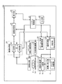
図1は、第1の実施形態に係るX線診断装置100の構成の一例を示す図である。図1に示すように、第1の実施形態に係るX線診断装置100は、高電圧発生器11と、X線管12と、X線絞り装置13と、天板14と、Cアーム15と、X線検出器16とを備える。また、第1の実施形態に係るX線診断装置100は、Cアーム回転・移動機構17と、天板移動機構18と、Cアーム・天板機構制御部19と、X線制御部20と、システム制御部21と、入力部22と、表示部23とを備える。また、第1の実施形態に係るX線診断装置100は、画像処理部24と、画像記憶部25とを備える。
(First embodiment)
FIG. 1 is a diagram illustrating an example of a configuration of an X-ray diagnostic apparatus 100 according to the first embodiment. As shown in FIG. 1, the X-ray diagnostic apparatus 100 according to the first embodiment includes a
また、図1に示すように、高電圧発生器11は、グリッド制御部11Aを備える。また、X線制御部20は、判定部20Aを備える。また、画像処理部24は、生成部24Aと、決定部24Bとを備える。なお、被検体Pは、X線診断装置100に含まれない。
As shown in FIG. 1, the
高電圧発生器11は、X線制御部20による制御の下、高電圧を発生し、発生した高電圧をX線管12に供給する。X線管12は、高電圧発生器11から供給される高電圧を用いて、X線を発生させる。すなわち、高電圧発生器11は、X線管12に供給する管電圧及び管電流を調整することで、X線管12から発生されるX線の線量を調整する。なお、高電圧発生器11が備えるグリッド制御部11Aの処理については、後述する。
The
X線絞り装置13は、X線制御部20による制御の下、X線管12が発生したX線を、被検体Pの関心領域に対して選択的に照射されるように絞り込む。例えば、X線絞り装置13は、スライド可能な4枚の絞り羽根を有する。X線絞り装置13は、X線制御部20による制御の下、これらの絞り羽根をスライドさせることで、X線管12が発生したX線を絞り込んで被検体Pに照射させる。天板14は、被検体Pを載せるベッドであり、図示しない寝台の上に配置される。
The X-ray diaphragm 13 narrows the X-ray generated by the
Cアーム15は、X線管12、X線絞り装置13及びX線検出器16を保持する。X線管12及びX線絞り装置13とX線検出器16とは、Cアーム15により被検体Pを挟んで対向するように配置される。
The C arm 15 holds the
X線検出器16は、被検体Pを透過したX線を検出する。例えば、X線検出器16は、マトリックス状に配列された検出素子を有する。各検出素子は、被検体Pを透過したX線を電気信号に変換して蓄積する。X線検出器16は、各検出素子に蓄積された電気信号を検出データとして画像処理部24に送信する。
The
Cアーム回転・移動機構17は、Cアーム15を回転及び移動させるための機構であり、天板移動機構18は、天板14を移動させるための機構である。Cアーム・天板機構制御部19は、システム制御部21による制御の下、Cアーム回転・移動機構17及び天板移動機構18を制御することで、Cアーム15の回転や移動、天板14の移動を調整する。
The C-arm rotating / moving mechanism 17 is a mechanism for rotating and moving the C-arm 15, and the top board moving mechanism 18 is a mechanism for moving the
X線制御部20は、高電圧発生器11、X線管12及びX線絞り装置13を制御することで、被検体Pに対してX線を照射させる。例えば、X線制御部20は、システム制御部21による制御の下、高電圧発生器11を制御し、X線管12に供給する管電圧及び管電流を調整することで、被検体Pに対して照射されるX線量やON/OFFを制御する。また、例えば、X線制御部20は、システム制御部21による制御の下、X線絞り装置13が有する絞り羽根の開度を調整することで、被検体Pに対して照射されるX線の照射範囲を制御する。なお、X線制御部20が備える判定部20Aの処理については、後述する。
The X-ray control unit 20 controls the
画像処理部24は、画像に関する処理を行う。例えば、生成部24Aは、X線検出器16によって検出された検出データを用いてX線画像データを生成する。具体的には、生成部24Aは、X線検出器16から受信した電気信号に対して、電流・電圧変換やA(Analog)/D(Digital)変換、パラレル・シリアル変換を行い、X線画像データを生成する。そして、生成部24Aは、生成した画像データを画像記憶部25に格納する。画像記憶部25は、画像処理部24によって生成された画像データを記憶する。なお、画像処理部24が備える決定部24Bの処理については、後述する。
The
入力部22は、X線診断装置100を操作する医師や技師などの操作者から各種指示を受け付ける。例えば、入力部22は、マウス、キーボード、ボタン、トラックボール、ジョイスティックなどを有する。入力部22は、操作者から受け付けた指示を、システム制御部21に転送する。
The input unit 22 receives various instructions from an operator such as a doctor or engineer who operates the X-ray diagnostic apparatus 100. For example, the input unit 22 includes a mouse, a keyboard, a button, a trackball, a joystick, and the like. The input unit 22 transfers the instruction received from the operator to the
表示部23は、操作者の指示を受け付けるためのGUI(Graphical User Interface)や、画像記憶部25が記憶する画像データなどを表示する。例えば、表示部23は、モニタを有する。なお、表示部23は、複数のモニタを有してもよい。
The display unit 23 displays a GUI (Graphical User Interface) for receiving an instruction from the operator, image data stored in the
システム制御部21は、X線診断装置100全体の動作を制御する。例えば、システム制御部21は、入力部22から転送された操作者の指示に従ってX線制御部20を制御することで、被検体Pに対してX線を照射させる。また、例えば、システム制御部21は、操作者の指示に従ってCアーム・天板機構制御部19を制御し、Cアーム15の回転や移動、天板14の移動を調整する。
The
また、システム制御部21は、操作者の指示に従って、画像処理部24による画像処理、若しくは解析処理などを制御する。また、システム制御部21は、操作者の指示を受け付けるためのGUIや画像記憶部25が記憶する画像などを、表示部23のモニタに表示するように制御する。
Further, the
ところで、X線画像診断では、被検体Pに対してX線のパルスを照射した場合に、パルスの下降波形が緩やかになることがある。この緩やかな下降波形(以下、波尾と称する)は、画像化に寄与しないばかりか、被検体Pにとって不要な被曝となってしまう。 By the way, in the X-ray image diagnosis, when the subject P is irradiated with an X-ray pulse, the falling waveform of the pulse may be gradual. This gradual descending waveform (hereinafter referred to as a wave tail) does not contribute to imaging, but is an unnecessary exposure for the subject P.
図2A及び図2Bは、波尾について説明するための図である。図2Aには、波尾30がある場合のX線のパルス波形の一例を示す。また、図2Bには、波尾がない場合のX線のパルス波形の一例を示す。図2A及び図2Bにおいて、横方向は、時間(経過時間)に対応する。なお、図2A及び図2Bでは、パルス透視や連続撮影等のように、複数のパルスを連続して照射する場合を例示するが、これに限らず、波尾は、連続透視や単回の撮影等のように、パルスを一回のみ照射する場合にも同様に生じうる現象である。
2A and 2B are diagrams for explaining the wave tail. FIG. 2A shows an example of an X-ray pulse waveform when there is a
図2Aに示すように、波尾30があると、各パルスの下降波形が緩やかになってしまう。この波尾30は、X線管12の管電流が低いほど生じやすい。画像化に用いられるのは矩形波のX線であるため(図2B参照)、波尾30は、画像化に寄与しないばかりか、被検体Pにとって不要な被曝となってしまう。
As shown in FIG. 2A, when there is a
この波尾30を除去(切断)するため、グリッド制御と呼ばれる技術が利用されている。グリッド制御とは、X線管12のグリッドに電圧をかけて熱電子の放出を抑えることで、波尾30を除去する技術である。
In order to remove (cut) the
図3は、グリッド制御について説明するための図である。図3には、X線管12の内部構造と熱電子の放出との関連を示す。図3の上段には、大焦点フィラメント31、小焦点フィラメント32、ターゲット33及びグリッド34等を含むX線管12の内部構造の一例を示す。また、図3の中段には、グリッド制御がオンの場合における陽極−陰極間の電圧と熱電子36の動きとの関連を例示する。また、図3の下段には、グリッド制御がオフの場合における陽極−陰極間の電圧と熱電子36の動きとの関連を例示する。なお、図3の上段、中段及び下段における陽極−陰極間の位置関係は、それぞれ対応している。
FIG. 3 is a diagram for explaining grid control. FIG. 3 shows the relationship between the internal structure of the
図3の上段及び下段に示すように、グリッド制御がオフの場合、陰極である大焦点フィラメント31又は小焦点フィラメント32から熱電子36が放出され、陽極であるターゲット33に衝突することで、X線が発生する。ここで、グリッド制御がオンになると、大焦点フィラメント31及び小焦点フィラメント32の間のコモン35とグリッド34との間に電圧(グリッド電圧、若しくはバイアス電圧とも称する)が印加され、図3の中段に示すように、熱電子36の放出が抑制される結果、X線の発生が抑制される。例えば、X線の各パルスが下降するタイミングでグリッド制御をオンにすることで、波尾30が抑制され、X線の各パルスが矩形波となる(図2B参照)。
As shown in the upper and lower stages of FIG. 3, when the grid control is off, thermoelectrons 36 are emitted from the
上記のグリッド制御は、例えば、撮影のように、X線を照射する照射条件が高電圧若しくは高電流である場合には、X線管12の仕様を逸脱してしまう場合があった。また、一般的に、透視におけるX線の照射条件は、撮影の照射条件よりも低電圧かつ低電流であり、波尾が生じやすい。このようなことから、グリッド制御は、パルス透視において広く利用されている。
The grid control described above may deviate from the specifications of the
一方、近年の画像処理技術の向上により、低線量のX線でも高画質の画像が得られるようになり、また、被検体Pに対する被曝量を低減させたいというニーズも高まっている。このような背景から、X線の照射条件は、透視に限らず撮影においても低く抑えることが望ましい。しかしながら、照射条件が低くなると、撮影においても波尾が生じ、被検体Pへの不要な被曝が増えてしまう場合がある。 On the other hand, with recent improvements in image processing technology, high-quality images can be obtained even with low-dose X-rays, and there is an increasing need to reduce the exposure dose to the subject P. From such a background, it is desirable to keep the X-ray irradiation conditions low not only in fluoroscopy but also in imaging. However, when the irradiation condition is lowered, a wave tail is generated even in imaging, and unnecessary exposure to the subject P may increase.
そこで、第1の実施形態に係るX線診断装置100は、以下の処理により、波尾による不要な被曝を適切に低減することを可能にする。 Therefore, the X-ray diagnostic apparatus 100 according to the first embodiment can appropriately reduce unnecessary exposure due to the wave tail by the following processing.
以下、第1の実施形態では、ある被検体Pについて透視を行ってから撮影を行う場合に、その撮影において、波尾による不要な被曝を適切に低減する場合を説明する。なお、実施形態はこれに限定されるものではなく、他の実施形態については、第2の実施形態以降にて説明する。 Hereinafter, in the first embodiment, when imaging is performed after performing fluoroscopy on a subject P, a case where unnecessary exposure due to wave tails is appropriately reduced in the imaging will be described. The embodiment is not limited to this, and other embodiments will be described from the second embodiment onward.
なお、以下の実施形態において、受像面におけるX線パタ−ンに含まれている情報を、直接又は間接的に記録する技法を「撮影」と称する。また、撮影のうち、規則的又は不規則な一連の負荷によるX線パタ−ンを記録するものを「連続撮影」と称する。また、一連のX線パタ−ンを連続的又は周期的に可視像とし、これを連続的に表示する技法を「透視」と称する。また、透視のうち、透視にかかる全期間にわたって連続的にX線を照射するものを「連続透視」と称し、パルス状のX線を間欠的に照射するものを「パルス透視」と称する。なお、本実施形態は、撮影や透視の定義によらず、効果を奏するものである。つまり、本実施形態は、X線パターンの記録の有無や表示の有無、表示態様等に関わらず、波尾による不要な被爆を適切に低減することを可能にする。 In the following embodiments, a technique for directly or indirectly recording information included in an X-ray pattern on an image receiving surface is referred to as “imaging”. Further, among the radiographing, an X-ray pattern recorded by a regular or irregular series of loads is referred to as “continuous radiography”. Further, a technique for continuously or periodically displaying a series of X-ray patterns and displaying them continuously is referred to as “perspective”. Further, among fluoroscopy, what continuously irradiates X-rays over the entire period of fluoroscopy is referred to as “continuous fluoroscopy”, and what is intermittently irradiated with pulsed X-rays is referred to as “pulse fluoroscopy”. In addition, this embodiment has an effect irrespective of the definition of photographing or fluoroscopy. That is, this embodiment makes it possible to appropriately reduce unnecessary exposure due to wave tails regardless of whether X-ray patterns are recorded, whether or not they are displayed, and how they are displayed.
図1の説明に戻る。決定部24Bは、X線検出器16によって検出されたX線の検出データに基づいて、照射条件を決定する。例えば、決定部24Bは、被検体Pの透視においてX線検出器16によって検出されたX線の検出データに基づいて、被検体Pの撮影における照射条件を決定する。
Returning to the description of FIG. The
一例としては、決定部24Bは、自動輝度調整(Automatic Brightness Control:ABC)によりX線の照射条件を決定する。ここで、ABCとは、複数のパルスによって複数の画像データを得る場合に、各パルスの照射条件を変化させて各画像データの輝度を一定に自動調整する処理である。例えば、決定部24Bは、あるパルスについて、生成部24Aによって生成された画像データを取得する。続いて、決定部24Bは、取得した画像データのうち、予め操作者により設定された関心領域内の平均輝度値を算出する。そして、決定部24Bは、算出した平均輝度値と、予め設定された基準値とを比較する。ここで、平均輝度値が基準値より高い場合には、決定部24Bは、次に生成される画像の平均輝度値が下がるように、X線の照射条件として管電圧[kV]及び管電流[mA]をより低い値に決定する。一方、平均輝度値が基準値より低い場合には、決定部24Bは、次に生成される画像の平均輝度値が上がるように、照射条件をより高い値に決定する。そして、決定部24Bは、決定した照射条件をX線制御部20の判定部20Aに出力する。
As an example, the determination unit 24B determines the X-ray irradiation conditions by automatic brightness adjustment (ABC). Here, ABC is a process of automatically adjusting the brightness of each image data constant by changing the irradiation condition of each pulse when a plurality of image data is obtained by a plurality of pulses. For example, the determination unit 24B acquires the image data generated by the generation unit 24A for a certain pulse. Subsequently, the determination unit 24B calculates an average luminance value within the region of interest set in advance by the operator from the acquired image data. Then, the determination unit 24B compares the calculated average luminance value with a preset reference value. Here, when the average luminance value is higher than the reference value, the determination unit 24B sets the tube voltage [kV] and the tube current [as the X-ray irradiation conditions so that the average luminance value of the image to be generated next decreases. mA] is determined to a lower value. On the other hand, when the average luminance value is lower than the reference value, the determination unit 24B determines the irradiation condition to a higher value so that the average luminance value of the next image to be generated is increased. Then, the determination unit 24B outputs the determined irradiation condition to the
このように、決定部24Bは、生成済みの画像データを用いたフィードバック制御により、各画像データの輝度を一定に自動調整する。なお、上記のABCは、連続撮影やパルス透視等、複数のパルスによって複数の画像データを得る場合のみならず、本実施形態で説明するように、透視の後に行われる撮影(単回撮影)の照射条件を決定する場合にも適用可能である。 As described above, the determination unit 24B automatically adjusts the luminance of each image data to be constant by feedback control using the generated image data. The above-described ABC is not only for obtaining a plurality of image data by a plurality of pulses, such as continuous imaging or pulse fluoroscopy, but also for imaging (single imaging) performed after fluoroscopy as described in the present embodiment. The present invention is also applicable when determining irradiation conditions.
なお、上記の説明では、照射条件として、X線管12の管電圧[kV]及び管電流[mA]が調整される場合を説明したが、実施形態はこれに限定されるものではない。例えば、管電圧[kV]及び管電流[mA]のうち、いずれか一方のみを調整する場合であってもよい。また、例えば、決定部24Bは、管電圧[kV]及び管電流時間積[mAs]を決定する場合であってもよい。
In the above description, the case where the tube voltage [kV] and the tube current [mA] of the
X線制御部20は、例えば、決定部24Bによって決定された照射条件に基づいて、高電圧発生器11、X線管12及びX線絞り装置13を制御することで、被検体Pに対してX線を照射させる。また、X線制御部20において、判定部20Aは、以下の処理を実行する。
The X-ray control unit 20 controls the
判定部20Aは、X線管12から照射されるX線の照射条件に応じて、X線管12のグリッド34に電圧を印加するか否かを判定する。例えば、判定部20Aは、決定部24Bによって照射条件が決定された後に、その照射条件に基づくX線が照射される場合に、グリッド34に電圧を印加するか否かをその照射条件に応じて判定する。
The determination unit 20 </ b> A determines whether to apply a voltage to the
一例としては、判定部20Aは、照射条件としてのX線の管電圧[kV]及び管電流[mA]が、予め設定されるそれぞれの閾値より低い場合に、グリッド34に電圧を印加すると判定する。例えば、判定部20Aは、決定部24Bによって決定された管電圧[kV]が第1閾値以下であるか否かを判定する。そして、管電圧[kV]が第1閾値以下である場合には、判定部20Aは、決定部24Bによって決定された管電流[mA]が第2閾値以下であるか否かを判定する。そして、管電流[mA]が第2閾値以下である場合には、判定部20Aは、決定された照射条件ではグリッド制御を行うと判定する。そして、判定部20Aは、グリッド制御を行う旨の判定結果を高電圧発生器11のグリッド制御部11Aへ通知する。
As an example, the
一方、管電圧[kV]が第1閾値より大きい場合、若しくは、管電流[mA]が第2閾値より大きい場合には、判定部20Aは、決定された照射条件ではグリッド制御を行わないと判定する。そして、判定部20Aは、グリッド制御を行わない旨の判定結果を高電圧発生器11のグリッド制御部11Aへ通知する。
On the other hand, when the tube voltage [kV] is larger than the first threshold or when the tube current [mA] is larger than the second threshold, the
このように、判定部20Aは、決定部24Bにより決定された照射条件に応じて、X線管12のグリッドに電圧を印加するか否かを判定する。なお、上記の第1閾値及び第2閾値は、X線管12の仕様に基づいて決定される。つまり、これらの閾値は、照射条件がX線管12の仕様を満たす範囲内で適切に波尾が抑制されるように設定される。
As described above, the
グリッド制御部11Aは、判定部20Aによって電圧を印加すると判定された場合に、グリッド34に電圧を印加する。例えば、グリッド制御部11Aは、判定部20Aによって電圧を印加すると判定された場合に、図3のグリッド制御を行うことで、波尾を抑制する。
The grid control unit 11A applies a voltage to the
例えば、グリッド制御部11Aは、判定部20Aから受け付けた判定結果がグリッド制御を行う旨のものであれば、対応する照射条件に基づくX線のパルスが照射され、そのパルスが下降するタイミングで、グリッド34に電圧を印加する。これにより、グリッド制御部11Aは、パルスの照射に伴う波尾の発生を抑制する。
For example, if the determination result received from the
一方、グリッド制御部11Aは、判定部20Aから受け付けた判定結果がグリッド制御を行わない旨のものであれば、対応する照射条件に基づくX線のパルスが照射されても、グリッド34に電圧を印加しない。
On the other hand, if the determination result received from the
このように、例えば、グリッド制御部11Aは、判定部20Aによって電圧を印加すると判定された場合に、グリッド制御を行う。
Thus, for example, the grid control unit 11A performs grid control when it is determined by the
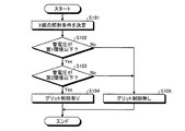
図4は、第1の実施形態に係るX線診断装置100による処理を説明するためのフローチャートである。図4に示す例では、透視におけるX線の照射条件から撮影時の照射条件を決定することが予め設定されており、透視が行われた後に図4の各処理が実行される。 FIG. 4 is a flowchart for explaining processing by the X-ray diagnostic apparatus 100 according to the first embodiment. In the example shown in FIG. 4, it is set in advance to determine the irradiation condition at the time of imaging from the X-ray irradiation condition in fluoroscopy, and after the fluoroscopy is performed, each process of FIG. 4 is executed.
図4に示すように、透視が行われると、決定部24Bは、X線検出器16によって検出されたX線の検出データに基づいて、X線の照射条件を決定する(ステップS101)。例えば、決定部24Bは、自動輝度調整(Automatic Brightness Control:ABC)によりX線の照射条件を決定する。 As shown in FIG. 4, when fluoroscopy is performed, the determination unit 24B determines X-ray irradiation conditions based on X-ray detection data detected by the X-ray detector 16 (step S101). For example, the determination unit 24B determines the X-ray irradiation condition by automatic brightness adjustment (ABC).
続いて、判定部20Aは、決定部24Bによって決定された管電圧[kV]が第1閾値以下であるか否かを判定する(ステップS102)。そして、管電圧[kV]が第1閾値以下である場合には(ステップS102,Yes)、判定部20Aは、決定部24Bによって決定された管電流[mA]が第2閾値以下であるか否かを判定する(ステップS103)。そして、管電流[mA]が第2閾値以下である場合には(ステップS103,Yes)、判定部20Aは、グリッド制御あり、つまり、決定された照射条件ではグリッド制御を行うと判定する(ステップS104)。そして、判定部20Aは、グリッド制御を行う旨の判定結果をグリッド制御部11Aへ通知する。この場合、グリッド制御部11Aは、対応する照射条件に基づくX線のパルスが照射され、そのパルスが下降するタイミングで、グリッド34に電圧を印加する。
Subsequently, the
一方、管電圧[kV]が第1閾値より大きい場合(ステップS102,No)、若しくは、管電流[mA]が第2閾値より大きい場合には(ステップS103,No)、判定部20Aは、グリッド制御なし、つまり、決定された照射条件ではグリッド制御を行わないと判定する(ステップS105)。そして、判定部20Aは、グリッド制御を行わない旨の判定結果をグリッド制御部11Aへ通知する。この場合、グリッド制御部11Aは、対応する照射条件に基づくX線のパルスが照射されても、グリッド34に電圧を印加しない。
On the other hand, when the tube voltage [kV] is larger than the first threshold value (step S102, No), or when the tube current [mA] is larger than the second threshold value (step S103, No), the
なお、図4は一例に過ぎない。例えば、管電圧[kV]による判定処理であるステップS102の処理、及び、管電流[mA]による判定処理であるステップS103の処理は、必ずしも上記の順序で実行されなくてもよい。例えば、管電流[mA]による判定処理が実行された後に、管電圧[kV]による判定処理が実行されてもよい。また、管電流[mA]による判定処理、及び、管電圧[kV]による判定処理のうち、いずれか一方のみが実行される場合であってもよい。 Note that FIG. 4 is merely an example. For example, the process of step S102, which is a determination process based on the tube voltage [kV], and the process of step S103, which is a determination process based on the tube current [mA], do not necessarily have to be executed in the above order. For example, after the determination process using the tube current [mA] is executed, the determination process using the tube voltage [kV] may be executed. In addition, only one of the determination process based on the tube current [mA] and the determination process based on the tube voltage [kV] may be executed.
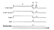
図5は、第1の実施形態に係るX線診断装置100による処理を説明するためのタイミングチャートである。図5において、横方向は、時間(経過時間)に対応する。また、「X−RAY ON」は、X線のパルスを照射可能なタイミングを表す。また、「X−RAY Actual」は、X線のパルスが実際に照射されるタイミングを表す。また、「Image」は、X線による画像化が行われるタイミングを表す。また、「ABC」は、決定部24BにおけるABCによりX線の照射条件が決定されるタイミングを表す。また、「照射条件通知」は、決定部24Bから判定部20AへX線の照射条件が通知されるタイミングを表す。
FIG. 5 is a timing chart for explaining processing by the X-ray diagnostic apparatus 100 according to the first embodiment. In FIG. 5, the horizontal direction corresponds to time (elapsed time). “X-RAY ON” represents a timing at which an X-ray pulse can be irradiated. “X-RAY Actual” represents the timing at which an X-ray pulse is actually emitted. “Image” represents a timing at which imaging with X-rays is performed. “ABC” represents the timing when the X-ray irradiation condition is determined by ABC in the determination unit 24B. The “irradiation condition notification” represents a timing at which the determination unit 24B notifies the
図5に示すように、期間T1において、X線制御部20の制御によりX線のパルスが被検体Pに照射され、連続透視による画像化が行われる。そして、この画像化のデータに基づいて、決定部24Bは、期間T2において、ABCによりX線の照射条件を決定し、決定した照射条件をX線制御部20へ通知する。X線制御部20は、決定部24Bによって決定された照射条件に基づいて、期間T3において撮影を行う。ここで、X線制御部20の判定部20Aは、通知された照射条件に応じて、グリッド34に電圧を印加するか否かを判定する。そして、判定部20Aは、判定結果を高電圧発生器11のグリッド制御部11Aへ通知する。グリッド制御部11Aは、通知された判定結果がグリッド制御を行う旨のものであれば、期間T3のパルスが下降するタイミングでグリッド34に電圧を印加する。これにより、グリッド制御部11Aは、パルスの照射に伴う波尾30の発生を抑制する。
As shown in FIG. 5, in a period T1, the subject P is irradiated with an X-ray pulse under the control of the X-ray control unit 20, and imaging by continuous fluoroscopy is performed. Based on this imaging data, the determination unit 24B determines the X-ray irradiation conditions by ABC in the period T2, and notifies the X-ray control unit 20 of the determined irradiation conditions. The X-ray control unit 20 performs imaging in the period T3 based on the irradiation condition determined by the determination unit 24B. Here, the
なお、図5は一例に過ぎない。例えば、図5では、透視として連続透視が行われる場合を説明したが、これに限定されるものではなく、例えば、パルス透視が行われる場合であってもよい。また、例えば、期間T3の撮影において、撮影時の照射線量を測定して撮影時間を制御する自動露出制御(Automatic Exposure Control:AEC)が適用される場合であってもよい。 Note that FIG. 5 is merely an example. For example, FIG. 5 illustrates the case where continuous fluoroscopy is performed as fluoroscopy, but the present invention is not limited to this. For example, pulse fluoroscopy may be performed. In addition, for example, automatic exposure control (AEC) for measuring the irradiation dose at the time of shooting and controlling the shooting time may be applied in shooting during the period T3.
上述してきたように、第1の実施形態に係るX線診断装置100は、X線の照射条件に応じて、グリッド制御を行う。このため、X線診断装置100は、波尾による不要な被曝を適切に低減することができる。 As described above, the X-ray diagnostic apparatus 100 according to the first embodiment performs grid control according to the X-ray irradiation conditions. For this reason, the X-ray diagnostic apparatus 100 can appropriately reduce unnecessary exposure due to the wave tail.
例えば、X線診断装置100は、ある被検体Pについて透視を行った後に、その透視の結果に基づいて自動的にX線の照射条件を決定して撮影を行う場合がある。この場合、X線診断装置100は、決定した照射条件に応じて、グリッド制御の要否を自動的に判定し、適宜グリッド制御を行う。このように、X線診断装置100は、照射条件が自動的に決定される場合にも、波尾による不要な被曝を適切に低減することができる。 For example, the X-ray diagnostic apparatus 100 may perform imaging after performing fluoroscopy on a subject P and then automatically determining X-ray irradiation conditions based on the fluoroscopy results. In this case, the X-ray diagnostic apparatus 100 automatically determines whether or not grid control is necessary according to the determined irradiation condition, and appropriately performs grid control. As described above, the X-ray diagnostic apparatus 100 can appropriately reduce unnecessary exposure due to the wave tail even when the irradiation condition is automatically determined.
なお、第1の実施形態では、透視に基づいて撮影の照射条件が決定される場合を説明したが、実施形態はこれに限定されるものではない。例えば、準備用に低線量の撮影を行ってから撮影を行う場合にも、1回目の撮影の照射条件を用いて2回目の撮影の照射条件を決める場合にも適用されてもよい。 In the first embodiment, the case where the irradiation condition for photographing is determined based on fluoroscopy has been described. However, the embodiment is not limited to this. For example, the present invention may be applied to the case where imaging is performed after low-dose imaging for preparation, or to the case where the irradiation conditions for the second imaging are determined using the irradiation conditions for the first imaging.
また、例えば、第1の実施形態では、X線の照射条件が決定部24Bにより決定される場合を説明したが、実施形態はこれに限定されるものではない。例えば、操作者からの指示により、X線の照射条件が予め登録されている場合であってもよい。この場合、例えば、判定部20Aは、登録済みの照射条件を読み出して、読み出した照射条件に応じて、X線管12のグリッド34に電圧を印加するか否かを判定する。そして、グリッド制御部11Aは、判定部20Aによって電圧を印加すると判定された場合に、グリッド34に電圧を印加する。すなわち、X線診断装置100は、必ずしも決定部24Bを備えていなくてもよい。
For example, in the first embodiment, the case where the X-ray irradiation condition is determined by the determination unit 24B has been described, but the embodiment is not limited thereto. For example, an X-ray irradiation condition may be registered in advance by an instruction from the operator. In this case, for example, the
(第2の実施形態)
上記の第1の実施形態では、透視に基づいて撮影の照射条件が決定される場合を説明したが、実施形態はこれに限定されるものではない。例えば、実施形態は、連続撮影に適用される場合であってもよい。そこで、第2の実施形態では、連続撮影に適用される場合を説明する。
(Second Embodiment)
In the first embodiment described above, the case where the irradiation condition for photographing is determined based on fluoroscopy has been described, but the embodiment is not limited to this. For example, the embodiment may be applied to continuous shooting. Therefore, in the second embodiment, a case where it is applied to continuous shooting will be described.
第2の実施形態に係るX線診断装置100は、図1に示したX線診断装置100の構成と基本的に同様であるが、処理の一部が相違する。そこで、第2の実施形態では、第1の実施形態と相違する点について説明することとし、同様の点については説明を省略する。 The X-ray diagnostic apparatus 100 according to the second embodiment is basically the same as the configuration of the X-ray diagnostic apparatus 100 shown in FIG. 1, but part of the processing is different. Therefore, in the second embodiment, only differences from the first embodiment will be described, and description of similar points will be omitted.
第2の実施形態に係る決定部24Bは、X線のパルスが複数回連続して照射されるごとに、X線の照射条件を決定する。また、第2の実施形態に係る判定部20Aは、決定部24Bによって照射条件が決定されるごとに、照射条件に基づくX線が照射される場合に、電圧を印加するか否かを、その照射条件に応じて判定する。以下、第2の実施形態に係る処理を、タイミングチャートを用いて説明する。
The determination unit 24B according to the second embodiment determines the X-ray irradiation condition each time the X-ray pulse is continuously irradiated a plurality of times. In addition, the
図6は、第2の実施形態に係るX線診断装置100による処理を説明するためのタイミングチャートである。図6において、横方向は、時間(経過時間)に対応する。また、「X−RAY ON」は、X線のパルスを照射可能なタイミングを表す。また、「X−RAY Actual」は、X線のパルスが実際に照射されるタイミングを表す。また、「Image」は、X線による画像化が行われるタイミングを表す。また、「ABC」は、決定部24BにおけるABCによりX線の照射条件が決定されるタイミングを表す。また、「照射条件通知」は、決定部24Bから判定部20AへX線の照射条件が通知されるタイミングを表す。
FIG. 6 is a timing chart for explaining processing by the X-ray diagnostic apparatus 100 according to the second embodiment. In FIG. 6, the horizontal direction corresponds to time (elapsed time). “X-RAY ON” represents a timing at which an X-ray pulse can be irradiated. “X-RAY Actual” represents the timing at which an X-ray pulse is actually emitted. “Image” represents a timing at which imaging with X-rays is performed. “ABC” represents the timing when the X-ray irradiation condition is determined by ABC in the determination unit 24B. The “irradiation condition notification” represents a timing at which the determination unit 24B notifies the
図6に示すように、期間T1においてX線制御部20の制御によりX線のパルスが被検体Pに照射されると、期間T2において画像化が行われる。そして、この画像化のデータに基づいて、決定部24Bは、期間T3においてABCによりX線の照射条件を決定し、期間T4において決定した照射条件をX線制御部20へ通知する。X線制御部20は、決定部24Bによって決定された照射条件に基づいて、期間T5において撮影を行う。ここで、X線制御部20の判定部20Aは、通知された照射条件に応じて、グリッド34に電圧を印加するか否かを判定する。そして、判定部20Aは、判定結果を高電圧発生器11のグリッド制御部11Aへ通知する。グリッド制御部11Aは、通知された判定結果がグリッド制御を行う旨のものであれば、期間T5のパルスが下降するタイミングでグリッド34に電圧を印加する。これにより、グリッド制御部11Aは、パルスの照射に伴う波尾30の発生を抑制する。
As shown in FIG. 6, when an X-ray pulse is irradiated to the subject P under the control of the X-ray control unit 20 in the period T1, imaging is performed in the period T2. Based on this imaging data, the determination unit 24B determines the X-ray irradiation conditions by ABC in the period T3, and notifies the X-ray control unit 20 of the irradiation conditions determined in the period T4. The X-ray control unit 20 performs imaging in the period T5 based on the irradiation condition determined by the determination unit 24B. Here, the
なお、図6は一例に過ぎない。例えば、図6では、決定部24Bから通知されたX線の照射条件が、その直後の撮影(期間T5の撮影)に適用される場合を説明したが、これに限定されるものではない。例えば、決定部24Bから通知された照射条件は、期間T5より後の撮影に適用されればよい。ただし、決定部24Bから通知された照射条件は、可能な限り早い段階の撮影に適用することが好ましい。 Note that FIG. 6 is merely an example. For example, FIG. 6 illustrates the case where the X-ray irradiation condition notified from the determination unit 24B is applied to the immediately subsequent imaging (imaging in the period T5), but is not limited thereto. For example, the irradiation condition notified from the determination unit 24B may be applied to imaging after the period T5. However, it is preferable that the irradiation condition notified from the determination unit 24B is applied to imaging at the earliest possible stage.
また、期間T1の撮影等、期間T5以前の撮像におけるグリッド制御の要否については、第1の実施形態にて説明したように、予め透視を行っておき、その透視に基づいて決定される照射条件を用いて判定してもよいし、或いは、連続撮影用に操作者により予め設定された照射条件の初期値を用いて判定してもよい。 In addition, as described in the first embodiment, whether or not grid control is necessary for imaging before the period T5, such as imaging during the period T1, is performed in advance and is determined based on the fluoroscopy. It may be determined using a condition, or may be determined using an initial value of an irradiation condition preset by an operator for continuous shooting.
このように、第2の実施形態に係るX線診断装置100は、連続撮影においても、波尾による不要な被曝を適切に低減することができる。例えば、連続撮影中に被検体Pが動いてしまった場合、若しくはX線の照射方向を変更した場合等には、被検体Pの体厚が変化してしまう可能性がある。このような場合に、X線の照射条件が下がると、波尾が生じてしまう場合がある。このため、X線診断装置100は、X線の照射条件が一定以下に下がった場合に、グリッド制御を行うことで、波尾による不要な被曝を適切に低減することができる。 As described above, the X-ray diagnostic apparatus 100 according to the second embodiment can appropriately reduce unnecessary exposure due to the wave tail even in continuous imaging. For example, when the subject P moves during continuous imaging, or when the X-ray irradiation direction is changed, the body thickness of the subject P may change. In such a case, if the X-ray irradiation condition is lowered, a wave tail may occur. For this reason, the X-ray diagnostic apparatus 100 can appropriately reduce unnecessary exposure due to the wave tail by performing grid control when the X-ray irradiation condition falls below a certain level.
(第3の実施形態)
上記の第1及び第2の実施形態では、撮影においてグリッド制御の要否を判定する場合を説明したが、実施形態はこれに限定されるものではない。例えば、実施形態は、パルス透視においてグリッド制御の要否を判定する場合であってもよい。そこで、第3の実施形態では、パルス透視においてグリッド制御の要否を判定する場合を説明する。
(Third embodiment)
In the first and second embodiments described above, the case where the necessity of grid control is determined in photographing has been described, but the embodiment is not limited to this. For example, the embodiment may be a case where the necessity of grid control is determined in pulse fluoroscopy. Therefore, in the third embodiment, a case will be described in which the necessity of grid control is determined in pulse fluoroscopy.
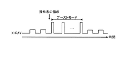
なお、第3の実施形態では、パルス透視の一例として、高線量率制御(High Level Control:HLC)透視が行われる場合を説明する。また、第3の実施形態では、HLC透視中に、一定期間通常の透視画像よりも高画質の画像を提供するためのモード(以下、ブーストモードと称する)が利用される。通常、パルス透視では、撮影の照射条件よりも低管電流のパルスを長時間照射するため、波尾が生じやすい。このため、通常のパルス透視では、グリッド制御を行うのが一般的である。これに対して、ブーストモードは、透視の照射条件よりも高管電流のパルスを短時間照射する透視モードであり、例えば、心臓のように、動きボケが生じる場合に有効なモードである。このため、ブーストモードでは、管電流が一定値以上照射される限り、波尾を抑制するためのグリッド制御を必要としない。しかしながら、第1の実施形態で説明したように、X線の照射条件は、低く抑えることが望ましく、これはブーストモードにおいても例外ではない。そこで、第3の実施形態では、パルス透視中のブーストモードにABCを適用し、パルスごとに照射条件を決定する場合において、波尾による不要な被曝を適切に低減することを目的として、グリッド制御の要否を判定する場合を説明する。 In the third embodiment, a case where high dose rate control (High Level Control: HLC) fluoroscopy is performed will be described as an example of pulse fluoroscopy. In the third embodiment, a mode for providing a higher quality image than a normal fluoroscopic image for a certain period during HLC fluoroscopy (hereinafter referred to as a boost mode) is used. Usually, in pulse fluoroscopy, a pulse with a low tube current is irradiated for a longer time than the imaging irradiation condition, so that a wave tail is likely to occur. For this reason, grid control is generally performed in normal pulse fluoroscopy. On the other hand, the boost mode is a fluoroscopic mode in which a pulse having a higher tube current than that of the fluoroscopic irradiation condition is irradiated for a short time, and is an effective mode when motion blur occurs, for example, like a heart. For this reason, in the boost mode, as long as the tube current is irradiated with a certain value or more, grid control for suppressing the wave tail is not required. However, as described in the first embodiment, it is desirable to keep the X-ray irradiation condition low, and this is no exception even in the boost mode. Therefore, in the third embodiment, when ABC is applied to the boost mode during the pulse fluoroscopy and the irradiation condition is determined for each pulse, the grid control is performed for the purpose of appropriately reducing unnecessary exposure due to the wave tail. The case of determining whether or not is necessary will be described.
第3の実施形態に係るX線診断装置100は、図1に示したX線診断装置100の構成と基本的に同様であるが、処理の一部が相違する。そこで、第3の実施形態では、第1の実施形態と相違する点について説明することとし、同様の点については説明を省略する。 The X-ray diagnostic apparatus 100 according to the third embodiment is basically the same as the configuration of the X-ray diagnostic apparatus 100 shown in FIG. 1, but part of the processing is different. Therefore, in the third embodiment, only points different from the first embodiment will be described, and description of similar points will be omitted.
第3の実施形態に係るシステム制御部21は、所定期間、ブーストモードによるパルス透視を実行する。このブーストモードは、操作者が入力部22を用いてモードを指定可能な状態で、システム制御部21に予め設定されている。なお、ブーストモードが所定期間行われるのは、この期間を超えるとX線の照射条件がX線管12の仕様を逸脱してしまう場合があるからである。また、ブーストモードは、グリッド34に電圧を印加せずにX線のパルスを所定期間連続して発生させるモードであると言える。
The
例えば、システム制御部21は、パルス透視が開始されると、ブーストモードを開始する。これにより、操作者は、パルス透視の開始時にブーストモードによる高画質画像を閲覧することができるので、ブーストモードが終了して画質が低下しても、高画質画像に描写されていた画像の特徴を思い描きつつ閲覧することができる。
For example, the
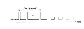
図7は、第3の実施形態に係るX線診断装置100による処理を説明するためのタイミングチャートである。図7において、縦方向は、管電流[mA]に対応し、横方向は、時間(経過時間)に対応する。なお、図7に示す例では、ブーストモード期間中には照射条件に応じてグリッド制御の要否が判定され、ブーストモード期間外には通常のパルス透視が行われる場合を説明する。 FIG. 7 is a timing chart for explaining processing by the X-ray diagnostic apparatus 100 according to the third embodiment. In FIG. 7, the vertical direction corresponds to the tube current [mA], and the horizontal direction corresponds to time (elapsed time). In the example illustrated in FIG. 7, a case will be described in which the necessity of grid control is determined according to the irradiation condition during the boost mode period, and normal pulse fluoroscopy is performed outside the boost mode period.
図7に示すように、決定部24Bは、ブーストモードにおいて、各パルスによって画像化が行われるごとに、この画像化のデータに基づいて、ABCによりX線の照射条件を決定する。そして、判定部20Aは、決定された照射条件に応じて、グリッド34に電圧を印加するか否かを判定する。判定部20Aは、判定結果を高電圧発生器11のグリッド制御部11Aへ通知する。グリッド制御部11Aは、通知された判定結果がグリッド制御を行う旨のものであれば、パルスが下降するタイミングでグリッド34に電圧を印加する。これにより、グリッド制御部11Aは、パルスの照射に伴う波尾の発生を抑制する。
As illustrated in FIG. 7, the determination unit 24B determines the X-ray irradiation condition by ABC based on the imaging data every time imaging is performed with each pulse in the boost mode. Then, the
そして、所定期間が経過して、ブーストモードが終了すると、通常のパルス透視に移行する。この通常のパルス透視では、各パルスが照射されるごとにグリッド制御が行われる。例えば、X線制御部20は、X線のパルスを発生させる際に、グリッド制御部11Aに対してグリッド制御を行う旨の指示を通知する。グリッド制御部11Aは、通知された指示を受け付けると、X線管12により発生したパルスが下降するタイミングでグリッド34に電圧を印加する。これにより、グリッド制御部11Aは、パルスの照射に伴う波尾の発生を抑制する。
Then, when the predetermined period has elapsed and the boost mode ends, the routine shifts to normal pulse fluoroscopy. In this normal pulse fluoroscopy, grid control is performed every time each pulse is irradiated. For example, the X-ray control unit 20 notifies the grid control unit 11A of an instruction to perform grid control when generating an X-ray pulse. Upon receiving the notified instruction, the grid control unit 11A applies a voltage to the
なお、図7の例では、ブーストモード期間中に照射される各パルスでの画像化においてグリッド制御の要否を判定する場合を説明したが、これに限らず、ブーストモード期間外のパルスでの画像化においてもグリッド制御の要否を判定してもよい。 In the example of FIG. 7, the case where the necessity of grid control is determined in the imaging with each pulse irradiated during the boost mode period has been described. The necessity of grid control may also be determined in imaging.
このように、第3の実施形態に係るX線診断装置100は、パルス透視中のブーストモードにABCを適用し、パルスごとに照射条件を決定する場合において、波尾による不要な被曝を適切に低減することができる。 As described above, the X-ray diagnostic apparatus 100 according to the third embodiment appropriately applies unnecessary exposure due to the wave tail when ABC is applied to the boost mode during pulse fluoroscopy and the irradiation condition is determined for each pulse. Can be reduced.
(第3の実施形態の変形例1)
上記の第3の実施形態では、パルス透視の開始とともにブーストモードが開始される場合を説明したが、実施形態はこれに限定されるものではなく、例えば、ブーストモードは、操作者の指示に応じて開始されてもよい。
(Modification 1 of 3rd Embodiment)
In the third embodiment described above, the case where the boost mode is started together with the start of the pulse fluoroscopy has been described. However, the embodiment is not limited to this. For example, the boost mode is determined according to an instruction from the operator. May be started.
例えば、システム制御部21は、パルス透視において、操作者からの指示に応じてブーストモードを開始する。
For example, the
図8は、第3の実施形態の変形例1に係るX線診断装置100による処理を説明するためのタイミングチャートである。図8において、縦方向は、管電流[mA]に対応し、横方向は、時間(経過時間)に対応する。 FIG. 8 is a timing chart for explaining processing by the X-ray diagnostic apparatus 100 according to Modification 1 of the third embodiment. In FIG. 8, the vertical direction corresponds to the tube current [mA], and the horizontal direction corresponds to time (elapsed time).
図8に示すように、パルス透視中に、ブーストモードを開始する旨の指示を操作者から受け付けると、システム制御部21は、ブーストモードを開始する。これにより、操作者は、任意のタイミングでブーストモードを開始することができる。なお、ブーストモードにおけるグリッド制御の要否の判定については、図7と同様であるので説明を省略する。
As illustrated in FIG. 8, when an instruction to start the boost mode is received from the operator during the pulse fluoroscopy, the
(第3の実施形態の変形例2)
また、上記のブーストモードは、所定の指示に連動させて開始してもよい。所定の指示とは、例えば、ステント固定表示用の画像処理等、特定の画像処理を実行する旨の指示である。なお、ステント固定表示用の画像処理とは、例えば、血管内インターベンション治療において、カテーテル位置の指標となるステントマーカを表示画面上の略同一の位置に固定させて表示するための画像処理技術である。このステント固定表示用の画像処理は、例えば、複数のパルスから複数の画像データがそれぞれ生成される場合に、各画像データにおけるステントマーカの位置を検出し、検出した位置が表示画面上で略一致するように各画像データを補正するものである。ここで、ステント固定表示用の画像処理とブーストモードとを連動させるのは、血管内インターベンション治療においては医師による精密な手技が求められるため、高画質の画像を表示するのが好ましいと考えられるからである。
(Modification 2 of the third embodiment)
Further, the boost mode may be started in conjunction with a predetermined instruction. The predetermined instruction is an instruction to execute specific image processing such as image processing for stent fixation display. The image processing for stent fixation display is, for example, an image processing technique for fixing and displaying a stent marker serving as an indicator of a catheter position at substantially the same position on a display screen in intravascular intervention treatment. is there. In this image processing for stent fixation display, for example, when a plurality of image data is generated from a plurality of pulses, the position of the stent marker in each image data is detected, and the detected positions substantially coincide on the display screen. In this way, each image data is corrected. Here, the reason why the image processing for stent fixation display and the boost mode are linked is that it is preferable to display a high-quality image because a precise procedure by a doctor is required in intravascular intervention treatment. Because.
例えば、システム制御部21は、予め設定された所定の指示を受け付けた場合に、パルス透視が開始されると、ブーストモードを開始する。
For example, the
図9は、第3の実施形態の変形例2に係るX線診断装置100による処理を説明するためのタイミングチャートである。図9において、縦方向は、管電流[mA]に対応し、横方向は、時間(経過時間)に対応する。 FIG. 9 is a timing chart for explaining processing by the X-ray diagnostic apparatus 100 according to the second modification of the third embodiment. In FIG. 9, the vertical direction corresponds to the tube current [mA], and the horizontal direction corresponds to time (elapsed time).
図9に示すように、所定の指示として、ステント固定表示用の画像処理を実行する旨の指示を操作者から受け付けると、システム制御部21は、パルス透視が開始された場合に、ブーストモードを開始するよう設定を行う。そして、実際にパルス透視が開始されると、まず、ブーストモードによる画像化が行われる。このように、X線診断装置100は、SMS等、高画質の画像化が望まれるような指示とブーストモードとを連動させておくことで、当該指示を操作者から受け付けた場合に、自動的にブーストモードを開始することができる。なお、ブーストモードにおけるグリッド制御の要否の判定については、図7と同様であるので説明を省略する。
As shown in FIG. 9, when an instruction to execute image processing for stent fixation display is received from an operator as a predetermined instruction, the
なお、図9では、ステント固定表示用の画像処理を実行する旨の指示とブーストモードとを連動させる場合を説明したが、これに限定されるものではない。例えば、高画質の画像を表示することが好ましいと考えられる画像処理がパルス透視や連続撮影と連動して実行される場合には、ブーストモードを連動させるのが好ましい。 In addition, although FIG. 9 demonstrated the case where the instruction | indication which performs the image process for a stent fixation display and boost mode were linked, it is not limited to this. For example, when image processing considered to be preferable to display a high-quality image is executed in conjunction with pulse fluoroscopy or continuous shooting, it is preferable to link the boost mode.
また、第3の実施形態で説明したブーストモードは、グリッド制御の要否判定とは別に実施されても上記の効果を奏するものである。 In addition, the boost mode described in the third embodiment has the above-described effects even if it is performed separately from the necessity determination of the grid control.
また、上述した第1〜第3の実施形態において、図示した各装置の各構成要素は機能概念的なものであり、必ずしも物理的に図示の如く構成されていることを要しない。すなわち、各装置の分散・統合の具体的形態は図示のものに限られず、その全部又は一部を、各種の負荷や使用状況等に応じて、任意の単位で機能的又は物理的に分散・統合して構成することができる。更に、各装置にて行なわれる各処理機能は、その全部又は任意の一部が、CPU及び当該CPUにて解析実行されるプログラムにて実現され、或いは、ワイヤードロジックによるハードウェアとして実現され得る。 In the first to third embodiments described above, each component of each illustrated device is functionally conceptual and does not necessarily need to be physically configured as illustrated. In other words, the specific form of distribution / integration of each device is not limited to the one shown in the figure, and all or a part of the distribution / integration is functionally or physically distributed in arbitrary units according to various loads or usage conditions. Can be integrated and configured. Further, all or a part of each processing function performed in each device may be realized by a CPU and a program analyzed and executed by the CPU, or may be realized as hardware by wired logic.
また、例えば、上記の実施形態では、X線診断装置100がCアーム15を備える場合を例示したが、実施形態はこれに限定されるものではない。例えば、X線診断装置100は、X線管12及びX線絞り装置13を支持する支持部(アーム)と、X線検出器16を支持する支持部とをそれぞれ個別に備えていてもよい。この場合、例えば、X線診断装置100は、これらの支持部を回転及び移動させるための機構を備える。
Further, for example, in the above embodiment, the case where the X-ray diagnostic apparatus 100 includes the C arm 15 is illustrated, but the embodiment is not limited to this. For example, the X-ray diagnostic apparatus 100 may include a support unit (arm) that supports the
また、上記の実施形態及び変形例で説明した処理は、あらかじめ用意された画像処理プログラムをパーソナルコンピュータやワークステーション等のコンピュータで実行することによって実現することができる。この画像処理プログラムは、インターネット等のネットワークを介して配布することができる。また、この画像処理プログラムは、ハードディスク、フレキシブルディスク(FD)、CD−ROM、MO、DVD等のコンピュータで読み取り可能な記録媒体に記録され、コンピュータによって記録媒体から読み出されることによって実行することもできる。 Further, the processing described in the above-described embodiments and modifications can be realized by executing an image processing program prepared in advance on a computer such as a personal computer or a workstation. This image processing program can be distributed via a network such as the Internet. The image processing program can also be executed by being recorded on a computer-readable recording medium such as a hard disk, a flexible disk (FD), a CD-ROM, an MO, or a DVD, and being read from the recording medium by the computer. .
以上、説明した少なくともひとつの実施形態によれば、波尾による不要な被曝を適切に低減することができる。 As described above, according to at least one embodiment described above, unnecessary exposure due to wave tails can be appropriately reduced.
本発明のいくつかの実施形態を説明したが、これらの実施形態は、例として提示したものであり、発明の範囲を限定することは意図していない。これら実施形態は、その他の様々な形態で実施されることが可能であり、発明の要旨を逸脱しない範囲で、種々の省略、置き換え、変更を行うことができる。これら実施形態やその変形は、発明の範囲や要旨に含まれると同様に、特許請求の範囲に記載された発明とその均等の範囲に含まれるものである。 Although several embodiments of the present invention have been described, these embodiments are presented by way of example and are not intended to limit the scope of the invention. These embodiments can be implemented in various other forms, and various omissions, replacements, and changes can be made without departing from the spirit of the invention. These embodiments and their modifications are included in the scope and gist of the invention, and are also included in the invention described in the claims and the equivalents thereof.
100 X線診断装置
11A グリッド制御部
12 X線管
20A 判定部
DESCRIPTION OF SYMBOLS 100 X-ray diagnostic apparatus 11A
Claims (12)
撮影又は透視におけるX線の照射条件に応じて、前記X線管のグリッドに電圧を印加するか否かを判定する判定部と、
前記判定部によって前記電圧を印加すると判定された場合に、前記照射条件に基づいて照射されるX線の波尾が除去されるよう前記グリッドに電圧を印加するグリッド制御部と
を備える、X線診断装置。 An X-ray tube that emits X-rays;
A determination unit that determines whether to apply a voltage to the grid of the X-ray tube according to the X-ray irradiation condition in imaging or fluoroscopy ;
A grid control unit configured to apply a voltage to the grid so as to remove the wave tail of the X-rays irradiated based on the irradiation conditions when the determination unit determines to apply the voltage. Diagnostic device.
撮影又は透視におけるX線の照射条件に応じて、前記X線管のグリッドに電圧を印加するか否かを判定する判定部と、
前記判定部によって前記電圧を印加すると判定された場合に、前記照射条件に基づいて照射されるX線の波尾が生じるタイミングで前記グリッドに電圧を印加するグリッド制御部と
を備える、X線診断装置。 An X-ray tube that emits X-rays;
A determination unit that determines whether to apply a voltage to the grid of the X-ray tube according to the X-ray irradiation condition in imaging or fluoroscopy ;
An X-ray diagnosis comprising: a grid control unit that applies a voltage to the grid at a timing when a wave tail of X-rays irradiated based on the irradiation condition occurs when the determination unit determines to apply the voltage. apparatus.
請求項1又は2に記載のX線診断装置。 The determination unit determines to apply the voltage when at least one of the tube voltage and tube current of the X-ray as the irradiation condition is lower than a preset threshold value,
The X-ray diagnostic apparatus according to claim 1 or 2 .
前記X線検出部によって検出されたX線の検出データに基づいて、前記照射条件を決定する決定部とを更に備え、
前記判定部は、前記決定部によって決定された照射条件に応じて、前記電圧を印加するか否かを判定する、
請求項1乃至3のいずれか1項に記載のX線診断装置。 An X-ray detector that detects the X-ray transmitted through the subject;
A determination unit that determines the irradiation condition based on X-ray detection data detected by the X-ray detection unit ;
The determination unit determines whether to apply the voltage according to the irradiation condition determined by the determination unit;
The X-ray diagnostic apparatus according to any one of claims 1 to 3 .
前記判定部は、前記決定部により決定された前記照射条件に応じて、前記被検体の撮影において前記X線管のグリッドに電圧を印加するか否かを判定する、
請求項4に記載のX線診断装置。 The determination unit determines the irradiation condition in imaging of the subject based on X-ray detection data detected by the X-ray detection unit in fluoroscopy of the subject,
The determination unit determines whether to apply a voltage to the grid of the X-ray tube in the imaging of the subject, according to the irradiation condition determined by the determination unit.
The X-ray diagnostic apparatus according to claim 4 .
前記判定部は、前記決定部によって前記照射条件が決定されるごとに、当該照射条件に基づく前記X線が照射される場合に、前記電圧を印加するか否かを当該照射条件に応じて
判定する、
請求項4に記載のX線診断装置。 The determination unit determines the irradiation condition each time the X-ray pulse is continuously irradiated a plurality of times,
The determination unit determines whether to apply the voltage according to the irradiation condition when the X-ray based on the irradiation condition is irradiated each time the irradiation condition is determined by the determination unit. To
The X-ray diagnostic apparatus according to claim 4 .
前記決定部は、前記モードにおいて前記X線のパルスが複数回連続して照射されるごとに、前記照射条件を決定する、
請求項6に記載のX線診断装置。 In the pulse fluoroscopy, further comprising a control unit that executes a mode for continuously generating X-ray pulses for a predetermined period without applying the voltage,
The determination unit determines the irradiation condition every time the X-ray pulse is continuously irradiated a plurality of times in the mode.
The X-ray diagnostic apparatus according to claim 6 .
請求項7に記載のX線診断装置。 The control unit starts the mode when the pulse fluoroscopy is started.
The X-ray diagnostic apparatus according to claim 7 .
請求項7に記載のX線診断装置。 In the pulse fluoroscopy, the control unit starts the mode in response to an instruction from an operator.
The X-ray diagnostic apparatus according to claim 7 .
請求項7に記載のX線診断装置。 The control unit starts the mode when the pulse fluoroscopy is started when a predetermined instruction set in advance is received,
The X-ray diagnostic apparatus according to claim 7 .
前記判定ステップで前記電圧を印加すると判定された場合に、前記照射条件に基づいて照射されるX線の波尾が除去されるよう前記グリッドに電圧を印加するグリッド制御ステップとA grid control step of applying a voltage to the grid so that the wave tail of the irradiated X-ray is removed based on the irradiation condition when it is determined that the voltage is applied in the determination step;
を有する、X線管制御方法。An X-ray tube control method comprising:
前記判定ステップで前記電圧を印加すると判定された場合に、前記照射条件に基づいて照射されるX線の波尾が生じるタイミングで前記グリッドに電圧を印加するグリッド制御ステップとA grid control step of applying a voltage to the grid at a timing when a wave tail of X-rays irradiated based on the irradiation condition occurs when it is determined that the voltage is applied in the determination step;
を有する、X線管制御方法。An X-ray tube control method comprising:
Priority Applications (2)
| Application Number | Priority Date | Filing Date | Title |
|---|---|---|---|
| JP2014205883A JP6441015B2 (en) | 2014-10-06 | 2014-10-06 | X-ray diagnostic apparatus and X-ray tube control method |
| US14/872,348 US10159455B2 (en) | 2014-10-06 | 2015-10-01 | X-ray diagnosis apparatus comprising judging circuitry to judge whether a voltage should be applied to a grid of an X-ray tube and grid controlling circuitry |
Applications Claiming Priority (1)
| Application Number | Priority Date | Filing Date | Title |
|---|---|---|---|
| JP2014205883A JP6441015B2 (en) | 2014-10-06 | 2014-10-06 | X-ray diagnostic apparatus and X-ray tube control method |
Publications (3)
| Publication Number | Publication Date |
|---|---|
| JP2016073449A JP2016073449A (en) | 2016-05-12 |
| JP2016073449A5 JP2016073449A5 (en) | 2017-11-16 |
| JP6441015B2 true JP6441015B2 (en) | 2018-12-19 |
Family
ID=55631911
Family Applications (1)
| Application Number | Title | Priority Date | Filing Date |
|---|---|---|---|
| JP2014205883A Active JP6441015B2 (en) | 2014-10-06 | 2014-10-06 | X-ray diagnostic apparatus and X-ray tube control method |
Country Status (2)
| Country | Link |
|---|---|
| US (1) | US10159455B2 (en) |
| JP (1) | JP6441015B2 (en) |
Families Citing this family (10)
| Publication number | Priority date | Publication date | Assignee | Title |
|---|---|---|---|---|
| US10701789B2 (en) | 2017-01-25 | 2020-06-30 | Electronics And Telecommunications Research Institute | Method for driving X-ray source |
| KR102169304B1 (en) * | 2017-01-25 | 2020-10-26 | 한국전자통신연구원 | Method for driving x-ray source |
| JP6729798B2 (en) * | 2017-04-13 | 2020-07-22 | 株式会社島津製作所 | X-ray equipment |
| KR101966794B1 (en) * | 2017-07-12 | 2019-08-27 | (주)선재하이테크 | X-ray tube for improving electron focusing |
| US20190189384A1 (en) * | 2017-12-18 | 2019-06-20 | Varex Imaging Corporation | Bipolar grid for controlling an electron beam in an x-ray tube |
| JP7392289B2 (en) * | 2019-05-22 | 2023-12-06 | コニカミノルタ株式会社 | Radiation image detection device |
| US11664184B2 (en) * | 2019-07-09 | 2023-05-30 | Varex Imaging Corporation | Electron gun driver |
| EP4039067A4 (en) * | 2019-10-03 | 2024-03-06 | Nano-X Imaging Ltd | Systems and methods for improving x-ray sources with switchable electron emitters |
| JP7211985B2 (en) * | 2020-01-08 | 2023-01-24 | 富士フイルム株式会社 | Imaging control device, method of operating imaging control device, operating program for imaging control device, and radiation imaging device |
| JP2022085288A (en) * | 2020-11-27 | 2022-06-08 | キヤノン株式会社 | Radiation imaging apparatus, radiation imaging system, control method of radiation imaging apparatus and program of the same |
Family Cites Families (99)
| Publication number | Priority date | Publication date | Assignee | Title |
|---|---|---|---|---|
| DE2917636A1 (en) * | 1979-05-02 | 1980-11-13 | Philips Patentverwaltung | X-RAY GENERATOR |
| DE3025107A1 (en) * | 1980-07-02 | 1982-01-14 | Siemens AG, 1000 Berlin und 8000 München | X-RAY DIAGNOSTIC DEVICE FOR RECORDING AND SCANNING |
| JPS58118732A (en) * | 1982-01-08 | 1983-07-14 | 株式会社東芝 | X-ray diagnostic apparatus |
| JPH05258893A (en) * | 1992-03-12 | 1993-10-08 | Toshiba Corp | X-ray diagnostic device |
| US5572566A (en) * | 1993-11-30 | 1996-11-05 | J. Morita Manufacturing Corporation | X-ray imaging apparatus and X-ray generation detector for activating the same |
| DE4430622C2 (en) * | 1994-08-29 | 1998-07-02 | Siemens Ag | Cathode system for an X-ray tube |
| US5949811A (en) * | 1996-10-08 | 1999-09-07 | Hitachi Medical Corporation | X-ray apparatus |
| JP3670439B2 (en) * | 1997-05-09 | 2005-07-13 | 株式会社日立メディコ | X-ray equipment |
| JP3413084B2 (en) * | 1997-11-20 | 2003-06-03 | キヤノン株式会社 | Radiation imaging apparatus and imaging method |
| JPH11311673A (en) * | 1998-04-28 | 1999-11-09 | Shimadzu Corp | Radiation image-pickup device |
| FR2778757B1 (en) * | 1998-05-12 | 2001-10-05 | Commissariat Energie Atomique | SYSTEM FOR ENTERING INFORMATION ON AN X-RAY SENSITIVE MEDIA |
| US6215850B1 (en) * | 1998-12-22 | 2001-04-10 | General Electric Company | X-ray beam control for an imaging system |
| US6175614B1 (en) * | 1999-05-07 | 2001-01-16 | Oec Medical Systems, Inc. | Method and apparatus for automatic sizing and positioning of ABS sampling window in an x-ray imaging system |
| WO2001039558A1 (en) * | 1999-11-23 | 2001-05-31 | Koninklijke Philips Electronics N.V. | X-ray examination apparatus with exposure control |
| US6456691B2 (en) * | 2000-03-06 | 2002-09-24 | Rigaku Corporation | X-ray generator |
| JP3548507B2 (en) * | 2000-08-01 | 2004-07-28 | キヤノン株式会社 | Radiation imaging device |
| US6775354B1 (en) * | 2000-09-20 | 2004-08-10 | Ge Medical Systems Global Technology Company, Llc | Method and apparatus for reducing high voltage breakdown events in X-ray tubes |
| US6553096B1 (en) * | 2000-10-06 | 2003-04-22 | The University Of North Carolina Chapel Hill | X-ray generating mechanism using electron field emission cathode |
| US6459765B1 (en) * | 2000-12-28 | 2002-10-01 | Ge Medical Systems Global Technology Company, Llc | Automatic exposure control and optimization in digital x-ray radiography |
| CN1251646C (en) * | 2001-03-29 | 2006-04-19 | 株式会社东芝 | X-ray system for diagnosing |
| DE10136947A1 (en) * | 2001-07-28 | 2003-02-06 | Philips Corp Intellectual Pty | X-ray system for generating X-rays |
| KR100567501B1 (en) * | 2001-08-29 | 2006-04-03 | 가부시끼가이샤 도시바 | X-ray generator |
| JP2003115399A (en) * | 2001-10-02 | 2003-04-18 | Toshiba Corp | X-ray diagnostic equipment |
| KR20040098041A (en) * | 2002-04-05 | 2004-11-18 | 하마마츠 포토닉스 가부시키가이샤 | X-ray tube adjustment apparatus, x-ray tube adjustment system, and x-ray tube adjustment method |
| CN100375583C (en) * | 2003-01-06 | 2008-03-12 | 皇家飞利浦电子股份有限公司 | High speed modulation of switched-focus X-ray tube |
| JP4304437B2 (en) * | 2003-06-20 | 2009-07-29 | 株式会社島津製作所 | Radiation imaging device |
| WO2005043463A1 (en) * | 2003-10-30 | 2005-05-12 | Koninklijke Philips Electronics N.V. | An x-ray examination apparatus and a method of controlling an output of an x-ray source of an x-ray examination apparatus |
| CN1846621A (en) * | 2005-04-15 | 2006-10-18 | 株式会社东芝 | CT scanner |
| US7280635B2 (en) * | 2005-12-01 | 2007-10-09 | Thomas Louis Toth | Processes and apparatus for managing low kVp selection and dose reduction and providing increased contrast enhancement in non-destructive imaging |
| EP3865864A1 (en) * | 2006-02-09 | 2021-08-18 | Leidos Security Detection & Automation, Inc. | Radiation scanning systems and methods |
| EP2010943A2 (en) * | 2006-04-21 | 2009-01-07 | American Science & Engineering, Inc. | X-ray imaging of baggage and personnel using arrays of discrete sources and multiple collimated beams |
| US7529344B2 (en) * | 2006-05-31 | 2009-05-05 | L-3 Communications Security and Detection Systems Inc. | Dual energy X-ray source |
| US7609815B2 (en) * | 2006-06-01 | 2009-10-27 | The Regents Of The University Of California | High brightness—multiple beamlets source for patterned X-ray production |
| JP4989120B2 (en) * | 2006-06-16 | 2012-08-01 | キヤノン株式会社 | Radiation imaging system and driving method thereof |
| JP2008073115A (en) * | 2006-09-19 | 2008-04-03 | Shimadzu Corp | X-ray radiographing apparatus |
| US8537965B2 (en) * | 2007-04-10 | 2013-09-17 | Arineta Ltd. | Cone-beam CT |
| US7627087B2 (en) * | 2007-06-28 | 2009-12-01 | General Electric Company | One-dimensional grid mesh for a high-compression electron gun |
| US7496180B1 (en) * | 2007-08-29 | 2009-02-24 | General Electric Company | Focal spot temperature reduction using three-point deflection |
| JP5464799B2 (en) * | 2007-11-16 | 2014-04-09 | キヤノン株式会社 | Image processing apparatus, image processing method, and program |
| US7646852B2 (en) * | 2007-12-31 | 2010-01-12 | Ge Security, Inc. | Method, a processor, and a system for tracking a focus of a beam |
| US7809114B2 (en) * | 2008-01-21 | 2010-10-05 | General Electric Company | Field emitter based electron source for multiple spot X-ray |
| US7826594B2 (en) * | 2008-01-21 | 2010-11-02 | General Electric Company | Virtual matrix control scheme for multiple spot X-ray source |
| JP4886713B2 (en) * | 2008-02-13 | 2012-02-29 | キヤノン株式会社 | X-ray imaging apparatus and control method thereof |
| US7801277B2 (en) * | 2008-03-26 | 2010-09-21 | General Electric Company | Field emitter based electron source with minimized beam emittance growth |
| US7792241B2 (en) * | 2008-10-24 | 2010-09-07 | General Electric Company | System and method of fast KVP switching for dual energy CT |
| WO2010061332A1 (en) * | 2008-11-26 | 2010-06-03 | Philips Intellectual Property & Standards Gmbh | Auxiliary grid electrode for x-ray tubes |
| CN102256548B (en) * | 2008-12-17 | 2014-03-05 | 皇家飞利浦电子股份有限公司 | X-ray examination apparatus and method |
| CN102415219B (en) * | 2009-04-22 | 2015-08-05 | 株式会社岛津制作所 | High voltage device and possess radiation source, the radioscopy picture pick-up device of this high voltage device |
| US8027433B2 (en) * | 2009-07-29 | 2011-09-27 | General Electric Company | Method of fast current modulation in an X-ray tube and apparatus for implementing same |
| DE102009037688B4 (en) * | 2009-08-17 | 2011-06-16 | Siemens Aktiengesellschaft | Apparatus and method for controlling an electron beam for the generation of X-radiation and X-ray tube |
| JP5596987B2 (en) * | 2010-01-21 | 2014-10-01 | 株式会社東芝 | X-ray fluoroscopic equipment |
| DE112011101007B4 (en) * | 2010-03-22 | 2024-02-29 | Nuray Technology Co., Ltd. | Multi-beam X-ray source with intelligent electronic control systems and methods therefor |
| US8487534B2 (en) * | 2010-03-31 | 2013-07-16 | General Electric Company | Pierce gun and method of controlling thereof |
| US8396185B2 (en) * | 2010-05-12 | 2013-03-12 | General Electric Company | Method of fast current modulation in an X-ray tube and apparatus for implementing same |
| CN102347187B (en) * | 2010-07-30 | 2016-01-20 | 株式会社理学 | Industrial x-ray generator |
| JP5661432B2 (en) * | 2010-11-17 | 2015-01-28 | キヤノン株式会社 | X-ray generator |
| EP2649634B1 (en) * | 2010-12-10 | 2018-07-04 | Canon Kabushiki Kaisha | Radiation generating apparatus and radiation imaging apparatus |
| JP5455880B2 (en) * | 2010-12-10 | 2014-03-26 | キヤノン株式会社 | Radiation generating tube, radiation generating apparatus and radiographic apparatus |
| JP5508340B2 (en) * | 2011-05-30 | 2014-05-28 | 富士フイルム株式会社 | Radiation image detection apparatus and method for controlling radiation image detection apparatus |
| JP5804777B2 (en) * | 2011-06-01 | 2015-11-04 | キヤノン株式会社 | X-ray generator tube and X-ray generator |
| JP5791401B2 (en) * | 2011-07-11 | 2015-10-07 | キヤノン株式会社 | Radiation generator and radiation imaging apparatus using the same |
| JP2013020792A (en) * | 2011-07-11 | 2013-01-31 | Canon Inc | Radiation generating device and radiography device using it |
| JP5713832B2 (en) * | 2011-08-03 | 2015-05-07 | キヤノン株式会社 | Radiation generator and radiation imaging apparatus using the same |
| JP5749609B2 (en) * | 2011-09-05 | 2015-07-15 | 富士フイルム株式会社 | Radiation imaging system and radiation source control device |
| JP5675537B2 (en) * | 2011-09-05 | 2015-02-25 | 富士フイルム株式会社 | Radiographic system, automatic exposure control method for radiographic system, and radiographic image detection apparatus |
| JP5675536B2 (en) * | 2011-09-05 | 2015-02-25 | 富士フイルム株式会社 | Radiographic system, automatic exposure control method for radiographic system, and radiographic image detection apparatus |
| JP5897020B2 (en) * | 2011-09-27 | 2016-03-30 | 富士フイルム株式会社 | Radiation imaging system, operating method thereof, and radiation image detection apparatus |
| CN103077874B (en) * | 2011-10-25 | 2015-09-02 | 中国科学院西安光学精密机械研究所 | Space X-ray Communication System and Method |
| JP5460674B2 (en) * | 2011-11-15 | 2014-04-02 | 富士フイルム株式会社 | Radiation imaging apparatus, control method therefor, and radiation imaging system |
| JP5984367B2 (en) * | 2011-12-02 | 2016-09-06 | キヤノン株式会社 | Radiation generator and radiation imaging system using the same |
| CN104135929A (en) * | 2012-02-01 | 2014-11-05 | 株式会社东芝 | Medical image diagnostic device |
| KR20130100630A (en) * | 2012-03-02 | 2013-09-11 | 삼성전자주식회사 | Electron emission device and x-ray generator including the same |
| JP5914404B2 (en) * | 2012-04-12 | 2016-05-11 | 富士フイルム株式会社 | X-ray exposure control device, X-ray image detection device, and X-ray imaging system |
| EP2852965A1 (en) * | 2012-05-22 | 2015-04-01 | Koninklijke Philips N.V. | Blanking of electron beam during dynamic focal spot jumping in circumferential direction of a rotating anode disk of an x-ray tube |
| JP5975733B2 (en) * | 2012-05-25 | 2016-08-23 | 富士フイルム株式会社 | Radiation image detection apparatus, drive control method thereof, and radiation imaging system |
| JP5890286B2 (en) * | 2012-09-18 | 2016-03-22 | 富士フイルム株式会社 | Radiation image detection device |
| JP6109512B2 (en) * | 2012-09-20 | 2017-04-05 | 東芝メディカルシステムズ株式会社 | Image processing apparatus, X-ray diagnostic apparatus and program |
| JP6207819B2 (en) * | 2012-09-20 | 2017-10-04 | 東芝メディカルシステムズ株式会社 | Image processing apparatus, X-ray diagnostic apparatus and program |
| JP6054119B2 (en) * | 2012-09-26 | 2016-12-27 | 東芝メディカルシステムズ株式会社 | X-ray CT system |
| JP2014107158A (en) * | 2012-11-28 | 2014-06-09 | Canon Inc | Radiation generator |
| US9072154B2 (en) * | 2012-12-21 | 2015-06-30 | Moxtek, Inc. | Grid voltage generation for x-ray tube |
| US9788809B2 (en) * | 2013-03-06 | 2017-10-17 | Canon Kabushiki Kaisha | Apparatus, method and computer-readable medium storing program for radiographic imaging with elapsed time control of radiation sensor apparatus |
| KR20140112270A (en) * | 2013-03-13 | 2014-09-23 | 삼성전자주식회사 | X-ray generator including heat sink block |
| JP5962555B2 (en) * | 2013-03-18 | 2016-08-03 | 株式会社島津製作所 | Fluoroscopic equipment |
| JP5744949B2 (en) * | 2013-03-29 | 2015-07-08 | 富士フイルム株式会社 | Radiation image detection apparatus and operation method thereof |
| KR20150001180A (en) * | 2013-06-26 | 2015-01-06 | 삼성전자주식회사 | The X-ray photographing apparatus and the method of operating the same |
| JP2015019987A (en) * | 2013-07-23 | 2015-02-02 | キヤノン株式会社 | Multi-source radiation generator and radiographic imaging system |
| JP6188470B2 (en) * | 2013-07-24 | 2017-08-30 | キヤノン株式会社 | Radiation generator and radiation imaging system using the same |
| CN104470178A (en) * | 2013-09-18 | 2015-03-25 | 清华大学 | X-ray device and CT device with same |
| KR20150043630A (en) * | 2013-10-14 | 2015-04-23 | 삼성전자주식회사 | X-ray image apparatus and control method for the same |
| KR102201407B1 (en) * | 2013-11-18 | 2021-01-12 | 삼성전자주식회사 | X-ray imaging apparatus and control method thereof |
| EP2878267B1 (en) * | 2013-11-28 | 2018-08-15 | Samsung Electronics Co., Ltd. | X-ray imaging apparatus and control method thereof |
| KR102216440B1 (en) * | 2013-12-04 | 2021-02-18 | 삼성전자주식회사 | Apparatus and method for generating of X-ray image |
| WO2015102115A1 (en) * | 2014-01-06 | 2015-07-09 | 株式会社 東芝 | X-ray computed tomography device, and photon counting ct device |
| JP6272043B2 (en) * | 2014-01-16 | 2018-01-31 | キヤノン株式会社 | X-ray generator tube, X-ray generator using the same, and X-ray imaging system |
| US9414801B2 (en) * | 2014-02-28 | 2016-08-16 | Samsung Electronics Co., Ltd. | X-ray imaging apparatus and control method therefor |
| KR20150139375A (en) * | 2014-06-03 | 2015-12-11 | 삼성전자주식회사 | X-ray imaging apparatus and control method for the same |
| KR102287248B1 (en) * | 2014-08-27 | 2021-08-06 | 삼성전자주식회사 | X-ray detector and control method thereof |
| US9888901B2 (en) * | 2016-02-19 | 2018-02-13 | Toshiba Medical Systems Corporation | X-ray diagnostic apparatus and X-ray CT apparatus |
-
2014
- 2014-10-06 JP JP2014205883A patent/JP6441015B2/en active Active
-
2015
- 2015-10-01 US US14/872,348 patent/US10159455B2/en active Active
Also Published As
| Publication number | Publication date |
|---|---|
| JP2016073449A (en) | 2016-05-12 |
| US10159455B2 (en) | 2018-12-25 |
| US20160095568A1 (en) | 2016-04-07 |
Similar Documents
| Publication | Publication Date | Title |
|---|---|---|
| JP6441015B2 (en) | X-ray diagnostic apparatus and X-ray tube control method | |
| JP6632847B2 (en) | X-ray diagnostic equipment | |
| JP5480467B2 (en) | Automatic protocol assistance equipment | |
| JP6858648B2 (en) | X-ray high-voltage device, X-ray imaging device, and judgment circuit | |
| JP7332734B2 (en) | X-ray computed tomography apparatus and control method | |
| WO2014133108A1 (en) | X-ray diagnostic device and image processing device | |
| JP6151009B2 (en) | X-ray diagnostic equipment | |
| JP2011182974A (en) | Controller for radiation source, radiographic system, and method for updating exposure conditions | |
| JP6494944B2 (en) | X-ray CT system | |
| JP6651332B2 (en) | X-ray image diagnostic apparatus and image processing method | |
| JP2019118699A (en) | X-ray diagnostic apparatus | |
| JP2018020113A (en) | X-ray diagnostic apparatus and image processing program | |
| JP2009268899A (en) | High velocity switching method in double energy computer tomography (ct) system | |
| JP2017217483A (en) | X-ray diagnostic apparatus and medical information processor | |
| JP2013192750A (en) | X-ray diagnostic apparatus and control method thereof | |
| JP7423188B2 (en) | Medical image processing equipment and X-ray diagnostic equipment | |
| JP6517087B2 (en) | X-ray diagnostic apparatus and image processing program | |
| JP2019187814A (en) | Medical image processing apparatus, x-ray diagnostic apparatus and medical image processing program | |
| JP2013172889A (en) | Image processor and x-ray image processor | |
| US20240032882A1 (en) | X-ray diagnostic apparatus, x-ray condition determination method, and non-transitory computer-readable medium | |
| JP6780949B2 (en) | X-ray diagnostic equipment | |
| JP7267727B2 (en) | X-ray diagnostic equipment | |
| JP7225006B2 (en) | X-ray diagnostic equipment | |
| JP7204410B2 (en) | X-ray diagnostic device, X-ray high voltage device and X-ray irradiation device | |
| JP2022162354A (en) | X-ray image processing device, x-ray diagnostic device, and program |
Legal Events
| Date | Code | Title | Description |
|---|---|---|---|
| A711 | Notification of change in applicant |
Free format text: JAPANESE INTERMEDIATE CODE: A711 Effective date: 20160513 |
|
| RD02 | Notification of acceptance of power of attorney |
Free format text: JAPANESE INTERMEDIATE CODE: A7422 Effective date: 20160928 |
|
| RD04 | Notification of resignation of power of attorney |
Free format text: JAPANESE INTERMEDIATE CODE: A7424 Effective date: 20161021 |
|
| A521 | Request for written amendment filed |
Free format text: JAPANESE INTERMEDIATE CODE: A523 Effective date: 20171005 |
|
| A621 | Written request for application examination |
Free format text: JAPANESE INTERMEDIATE CODE: A621 Effective date: 20171005 |
|
| A977 | Report on retrieval |
Free format text: JAPANESE INTERMEDIATE CODE: A971007 Effective date: 20180718 |
|
| A131 | Notification of reasons for refusal |
Free format text: JAPANESE INTERMEDIATE CODE: A131 Effective date: 20180724 |
|
| A521 | Request for written amendment filed |
Free format text: JAPANESE INTERMEDIATE CODE: A523 Effective date: 20180918 |
|
| TRDD | Decision of grant or rejection written | ||
| A01 | Written decision to grant a patent or to grant a registration (utility model) |
Free format text: JAPANESE INTERMEDIATE CODE: A01 Effective date: 20181023 |
|
| A61 | First payment of annual fees (during grant procedure) |
Free format text: JAPANESE INTERMEDIATE CODE: A61 Effective date: 20181121 |
|
| R150 | Certificate of patent or registration of utility model |
Ref document number: 6441015 Country of ref document: JP Free format text: JAPANESE INTERMEDIATE CODE: R150 |