JP5713832B2 - Radiation generator and radiation imaging apparatus using the same - Google Patents
Radiation generator and radiation imaging apparatus using the same Download PDFInfo
- Publication number
- JP5713832B2 JP5713832B2 JP2011169860A JP2011169860A JP5713832B2 JP 5713832 B2 JP5713832 B2 JP 5713832B2 JP 2011169860 A JP2011169860 A JP 2011169860A JP 2011169860 A JP2011169860 A JP 2011169860A JP 5713832 B2 JP5713832 B2 JP 5713832B2
- Authority
- JP
- Japan
- Prior art keywords
- radiation
- window
- insulating
- envelope
- insulating plate
- Prior art date
- Legal status (The legal status is an assumption and is not a legal conclusion. Google has not performed a legal analysis and makes no representation as to the accuracy of the status listed.)
- Expired - Fee Related
Links
Images


Classifications
-
- H—ELECTRICITY
- H01—ELECTRIC ELEMENTS
- H01J—ELECTRIC DISCHARGE TUBES OR DISCHARGE LAMPS
- H01J35/00—X-ray tubes
- H01J35/02—Details
- H01J35/16—Vessels; Containers; Shields associated therewith
- H01J35/18—Windows
-
- H—ELECTRICITY
- H01—ELECTRIC ELEMENTS
- H01J—ELECTRIC DISCHARGE TUBES OR DISCHARGE LAMPS
- H01J35/00—X-ray tubes
- H01J35/02—Details
- H01J35/04—Electrodes ; Mutual position thereof; Constructional adaptations therefor
-
- H—ELECTRICITY
- H01—ELECTRIC ELEMENTS
- H01J—ELECTRIC DISCHARGE TUBES OR DISCHARGE LAMPS
- H01J35/00—X-ray tubes
- H01J35/02—Details
- H01J35/16—Vessels; Containers; Shields associated therewith
-
- H—ELECTRICITY
- H01—ELECTRIC ELEMENTS
- H01J—ELECTRIC DISCHARGE TUBES OR DISCHARGE LAMPS
- H01J2235/00—X-ray tubes
- H01J2235/06—Cathode assembly
-
- H—ELECTRICITY
- H01—ELECTRIC ELEMENTS
- H01J—ELECTRIC DISCHARGE TUBES OR DISCHARGE LAMPS
- H01J2235/00—X-ray tubes
- H01J2235/12—Cooling
- H01J2235/1204—Cooling of the anode
-
- H—ELECTRICITY
- H01—ELECTRIC ELEMENTS
- H01J—ELECTRIC DISCHARGE TUBES OR DISCHARGE LAMPS
- H01J2235/00—X-ray tubes
- H01J2235/12—Cooling
- H01J2235/1216—Cooling of the vessel
-
- H—ELECTRICITY
- H01—ELECTRIC ELEMENTS
- H01J—ELECTRIC DISCHARGE TUBES OR DISCHARGE LAMPS
- H01J2235/00—X-ray tubes
- H01J2235/12—Cooling
- H01J2235/122—Cooling of the window
-
- H—ELECTRICITY
- H01—ELECTRIC ELEMENTS
- H01J—ELECTRIC DISCHARGE TUBES OR DISCHARGE LAMPS
- H01J2235/00—X-ray tubes
- H01J2235/12—Cooling
- H01J2235/1225—Cooling characterised by method
- H01J2235/1262—Circulating fluids
-
- H—ELECTRICITY
- H01—ELECTRIC ELEMENTS
- H01J—ELECTRIC DISCHARGE TUBES OR DISCHARGE LAMPS
- H01J2235/00—X-ray tubes
- H01J2235/12—Cooling
- H01J2235/1225—Cooling characterised by method
- H01J2235/1291—Thermal conductivity
-
- H—ELECTRICITY
- H01—ELECTRIC ELEMENTS
- H01J—ELECTRIC DISCHARGE TUBES OR DISCHARGE LAMPS
- H01J2235/00—X-ray tubes
- H01J2235/16—Vessels
-
- H—ELECTRICITY
- H01—ELECTRIC ELEMENTS
- H01J—ELECTRIC DISCHARGE TUBES OR DISCHARGE LAMPS
- H01J2235/00—X-ray tubes
- H01J2235/16—Vessels
- H01J2235/165—Shielding arrangements
- H01J2235/167—Shielding arrangements against thermal (heat) energy
-
- H—ELECTRICITY
- H01—ELECTRIC ELEMENTS
- H01J—ELECTRIC DISCHARGE TUBES OR DISCHARGE LAMPS
- H01J35/00—X-ray tubes
- H01J35/02—Details
- H01J35/04—Electrodes ; Mutual position thereof; Constructional adaptations therefor
- H01J35/08—Anodes; Anti cathodes
- H01J35/112—Non-rotating anodes
- H01J35/116—Transmissive anodes
-
- H—ELECTRICITY
- H01—ELECTRIC ELEMENTS
- H01J—ELECTRIC DISCHARGE TUBES OR DISCHARGE LAMPS
- H01J35/00—X-ray tubes
- H01J35/02—Details
- H01J35/16—Vessels; Containers; Shields associated therewith
- H01J35/18—Windows
- H01J35/186—Windows used as targets or X-ray converters
Description
本発明は、放射線発生装置及び放射線撮影装置に関し、特に絶縁性流体を充填した外囲器内に放射線発生管を備える放射線発生装置及びそれを用いた放射線撮影装置に関する。 The present invention relates to a radiation generation apparatus and a radiography apparatus, and more particularly to a radiation generation apparatus including a radiation generation tube in an envelope filled with an insulating fluid and a radiography apparatus using the radiation generation apparatus.
電子源から放出された電子をターゲットに照射することにより放射線を発生させる放射線発生装置として、密閉された内部に電子源とターゲットを配置した放射線発生管を、外囲器内に収納した放射線発生装置が知られている。放射線発生管内に配置される電子源としては、従来からフィラメント等の熱電子源が用いられている。熱電子源には、ブラウン管用の電子源として用いられる含浸型熱陰極電子放出素子等のように小型のものもある。熱電子源を用いた放射線発生管では、高温に加熱した熱電子源から放出された熱電子の電子束の一部を、ウエネルト電極、引出し電極、加速電極及びレンズ電極を通して高エネルギーに加速する。それと同時に電子束を所望の形状に成形した後、成形された電子束をタングステン等の金属で構成されたターゲットに照射して放射線を発生させる。 As a radiation generation device that generates radiation by irradiating a target with electrons emitted from an electron source, a radiation generation device in which a radiation generation tube in which an electron source and a target are arranged in a sealed interior is housed in an envelope It has been known. Conventionally, a thermal electron source such as a filament has been used as an electron source disposed in the radiation generating tube. Some thermoelectron sources are small, such as an impregnated hot cathode electron-emitting device used as an electron source for a cathode ray tube. In a radiation generating tube using a thermoelectron source, a part of the electron bundle of thermoelectrons emitted from a thermoelectron source heated to a high temperature is accelerated to high energy through a Wehnelt electrode, an extraction electrode, an acceleration electrode, and a lens electrode. At the same time, after forming the electron bundle into a desired shape, radiation is generated by irradiating the formed electron bundle onto a target made of a metal such as tungsten.
ところで、放射線撮影に好適な放射線を発生させるためには、放射線発生管内の陰極である電子源とターゲットとの間に40kV〜150kVという高電圧を印加し、電子束を高エネルギーに加速してターゲットに照射する必要がある。また、一般に外囲器は金属材料で形成され、電位が0Vに規定される。このため、電子源とターゲットとの間、及び放射線発生管と外囲器との間には数十kV以上の高電位差が生じることとなる。よって、長時間安定して放射線を発生させるためには、放射線発生装置がこのような高電圧において耐電圧性(耐圧性)を有することが求められる。 By the way, in order to generate radiation suitable for radiography, a high voltage of 40 kV to 150 kV is applied between an electron source which is a cathode in the radiation generating tube and the target, and the electron flux is accelerated to high energy to target. Need to be irradiated. In general, the envelope is made of a metal material, and the potential is regulated to 0V. For this reason, a high potential difference of several tens of kV or more is generated between the electron source and the target and between the radiation generating tube and the envelope. Therefore, in order to generate radiation stably for a long time, the radiation generator is required to have voltage resistance (pressure resistance) at such a high voltage.
特許文献1には、特に回転陽極X線管と外囲器との間で放電が発生するのを防ぐ目的で、回転陽極X線管と外囲器の内壁との間に冷却絶縁油を充填し耐電圧性を確保する技術が開示されている。具体的には外囲器を回転陽極X線管の軸方向に3分割し、外囲器中央部で回転陽極X線管を支持し、陽極側と陰極側をそれぞれカップ状支持部材で支持する構成をとっている。回転陽極X線管とカップ状支持部材との間によどみなく冷却絶縁油を流動させることで回転陽極X線管の表面に付着するスラッジを防止し、回転陽極X線管と外囲器との間の放電を低減している。 In Patent Document 1, a cooling insulating oil is filled between the rotary anode X-ray tube and the inner wall of the envelope for the purpose of preventing discharge particularly between the rotary anode X-ray tube and the envelope. However, a technique for ensuring voltage resistance is disclosed. Specifically, the envelope is divided into three in the axial direction of the rotary anode X-ray tube, the rotary anode X-ray tube is supported at the center of the envelope, and the anode side and the cathode side are respectively supported by cup-shaped support members. It has a configuration. By allowing the cooling insulating oil to flow smoothly between the rotary anode X-ray tube and the cup-shaped support member, sludge adhering to the surface of the rotary anode X-ray tube is prevented, and the rotation anode X-ray tube and the envelope The discharge between is reduced.
しかしながら、特許文献1に記載の技術では、回転陽極X線管と外囲器との間の距離によっては冷却絶縁油を流動させるための流出入口や回転陽極X線管のX線放出口を通して回転陽極X線管と外囲器との間で放電が発生しX線管が破損するおそれがあった。そして、放電によりX線管が破損すると、長時間安定してX線を発生させることができないという問題があった。 However, in the technique described in Patent Document 1, depending on the distance between the rotating anode X-ray tube and the envelope, the rotating insulating X-ray tube rotates through the outflow inlet for flowing the cooling insulating oil or the X-ray emitting port of the rotating anode X-ray tube. There was a risk of discharge occurring between the anode X-ray tube and the envelope, causing damage to the X-ray tube. When the X-ray tube is damaged by discharge, there is a problem that X-rays cannot be generated stably for a long time.
この問題の対策として、回転陽極X線管と外囲器の内壁との間の冷却絶縁油層を十分厚くする方法が考えられる。しかし、冷却絶縁油等の絶縁性液体の耐電圧性能は、他の絶縁部材のそれに比べて電極形状、電極表面性状、温度、不純物、対流等の影響を受けやすい。このため、駆動中200℃以上の高温になる回転陽極X線管と、外囲器の内壁との間の冷却絶縁油層の厚さの設定は放電を防ぐために十分に安全率を加える必要がある。その結果、外囲器が大きくなり、X線発生装置が大型化・高重量化していた。また、冷却絶縁油層を厚くすると冷却絶縁油層を通過する際のX線の減衰量が大きくなる。よって、X線撮影に必要なX線量を放出するためには、その減衰量を補うためにより高電圧、高電流、長時間駆動する必要があり、電力効率の低いX線発生装置となっていた。特に可般型X線発生装置等で電力効率の低さが問題となっていた。 As a countermeasure for this problem, a method of sufficiently thickening the cooling insulating oil layer between the rotary anode X-ray tube and the inner wall of the envelope can be considered. However, the withstand voltage performance of insulating liquids such as cooling insulating oil is more susceptible to the influence of electrode shape, electrode surface properties, temperature, impurities, convection, and the like than those of other insulating members. For this reason, the setting of the thickness of the cooling insulating oil layer between the rotating anode X-ray tube that becomes a high temperature of 200 ° C. or higher during driving and the inner wall of the envelope needs to add a sufficient safety factor to prevent discharge. . As a result, the envelope has become larger, and the X-ray generator has become larger and heavier. Further, when the cooling insulating oil layer is thickened, the amount of X-ray attenuation when passing through the cooling insulating oil layer increases. Therefore, in order to release the X-ray dose necessary for X-ray imaging, it is necessary to drive for a longer time with a higher voltage, a higher current to compensate for the attenuation, and the X-ray generator has low power efficiency. . In particular, low power efficiency has been a problem in portable X-ray generators and the like.
上述の問題は特許文献1に記載のような反射型の放射線発生装置に限った問題ではなく、透過型の放射線発生装置においても同様の問題があった。よって、反射型・透過型のいずれにおいても、放射線発生管と外囲器との間の距離をできるだけ短くして装置を小型化し、放射線発生管と外囲器との間で放電しにくいように耐電圧も確保し、かつ放射線の減衰量も低減することが求められる。本発明者らは絶縁性流体を充填した外囲器内に放射線発生管を備える構成において、放射線発生管に設けた放射線透過窓と、外囲器に設けた放射線取出窓との間に絶縁部材を配置することが、放射線発生管と外囲器との間の耐電圧の向上に有効であることを見出した。 The above-mentioned problem is not limited to the reflection-type radiation generator as described in Patent Document 1, and the transmission-type radiation generator has the same problem. Therefore, in both the reflection type and the transmission type, the distance between the radiation generator tube and the envelope is made as short as possible to reduce the size of the device so that the discharge between the radiation generator tube and the envelope is difficult. It is required to secure a withstand voltage and reduce radiation attenuation. In a configuration in which a radiation generating tube is provided in an envelope filled with an insulating fluid, the present inventors have an insulating member between a radiation transmitting window provided in the radiation generating tube and a radiation extraction window provided in the envelope. It has been found that the arrangement of is effective in improving the withstand voltage between the radiation generating tube and the envelope.
そこで、本発明は、絶縁性流体を充填した外囲器内に放射線発生管を備える構成において、装置の小型化、外囲器と放射線発生管との間の耐電圧の向上、放射線の減衰量の低減を実現した放射線発生装置及びそれを用いた放射線撮影装置の提供を目的とする。 Accordingly, the present invention provides a configuration in which a radiation generating tube is provided in an envelope filled with an insulating fluid, downsizing the device, improving the withstand voltage between the envelope and the radiation generating tube, and reducing the amount of radiation. An object of the present invention is to provide a radiation generation apparatus that realizes a reduction in the amount of radiation and a radiation imaging apparatus using the radiation generation apparatus.
上記課題を解決するために、本発明は、放射線を透過する第一の窓を有する外囲器と、
前記外囲器内に収納され、前記第一の窓と対向する位置に放射線を透過する第二の窓を有する放射線発生管と、
前記外囲器の内壁と前記放射線発生管との間に配置された絶縁性流体と、
を備える放射線発生装置であって、
前記第一の窓及びその周縁部と前記第二の窓及びその周縁部との間に、複数枚の絶縁性板材が隙間を空けて重なって配置されていることを特徴とする放射線発生装置を提供するものである。
In order to solve the above problems, the present invention includes an envelope having a first window that transmits radiation,
A radiation generating tube that is housed in the envelope and has a second window that transmits radiation at a position facing the first window;
An insulating fluid disposed between the inner wall of the envelope and the radiation generating tube;
A radiation generator comprising:
A radiation generating apparatus, wherein a plurality of insulating plate members are arranged with a gap between the first window and the peripheral edge thereof and the second window and the peripheral edge thereof. It is to provide.
本発明によれば、内部に絶縁性流体を充填した外囲器が有する第一の窓と、外囲器内に配置された放射線発生管が有する第二の窓と、を対向配置し、第一の窓及びその周縁部と第二の窓及びその周縁部との間に複数枚の絶縁性板材を、隙間を空けて並べて配置する。更に、絶縁性板材間の隙間は、第一の窓と第二の窓との間の耐電圧が、複数枚の絶縁性板材に換えて各絶縁性板材の厚さの合計と同じ厚さを持った絶縁性板材を配置した場合に比べて大きくなる隙間とする。このため、各絶縁性板材の厚さの合計と同じ厚さを持った絶縁性板材を配置した場合よりも第一の窓と第二の窓との間の耐電圧が向上する。これにより、複数枚の絶縁性板材の厚さを薄くしても耐電圧を確保できるため放射線減衰量を低減でき、絶縁性板材間における絶縁性流体の層の厚さも安全率分薄くできるため装置を小型化できる。 According to the present invention, the first window included in the envelope filled with the insulating fluid therein and the second window included in the radiation generating tube disposed in the envelope are arranged to face each other. A plurality of insulating plate members are arranged side by side with a gap between one window and its peripheral portion and the second window and its peripheral portion. Furthermore, the gap between the insulating plates is such that the withstand voltage between the first window and the second window is the same as the total thickness of each insulating plate instead of the plurality of insulating plates. The gap is larger than that in the case where an insulative plate is provided. For this reason, the withstand voltage between the 1st window and the 2nd window improves rather than the case where the insulating board material which has the same thickness as the sum total of the thickness of each insulating board material is arranged. As a result, withstand voltage can be ensured even if the thickness of a plurality of insulating plates is reduced, radiation attenuation can be reduced, and the thickness of the insulating fluid layer between insulating plates can be reduced by a safety factor. Can be miniaturized.
以下、本発明の放射線発生装置及び放射線撮影装置を具体的な実施形態で説明する。 Hereinafter, the radiation generator and the radiation imaging apparatus of the present invention will be described in specific embodiments.
〔第1の実施形態〕
図1は本実施形態の放射線発生装置11の断面模式図である。
[First Embodiment]
FIG. 1 is a schematic cross-sectional view of a
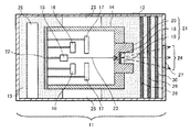
本実施形態の放射線発生装置(透過型放射線源)11は、外囲器12、絶縁性流体13、放射線発生管14、電子源15、第1制御電極16、第2制御電極17、透過型ターゲット18、ターゲット基板19、遮蔽部材20を有している。更に本実施形態の放射線発生装置11は、カソード支持部材22、保持部材25、電源回路26、第一の窓27、絶縁性板材28、29、30を有している。
The radiation generation apparatus (transmission type radiation source) 11 of this embodiment includes an
外囲器12は、放射線発生管14等の部材を収納するための容器である。外囲器12内には絶縁性流体13が充填されている。絶縁性流体13が充填された外囲器内には、外囲器12の内壁に固定された保持部材25によって胴部を保持された筒形の放射線発生管14が収納されており、絶縁性流体13は放射線発生管14の周囲を循環可能になっている。外囲器12の材料としては鉄、ステンレス、鉛、真鍮、銅等の金属が使用可能である。外囲器12内への絶縁性流体13の注入は、外囲器12の一部に絶縁性流体13の注入口(不図示)を設けることにより、その注入口から行うことができる。また、駆動中の放射線発生装置11で絶縁性流体13の温度が上昇し膨張したときに外囲器12内の圧力が上昇するのを避けるため、必要に応じて外囲器12の一部に弾性部材を用いた圧力調整口(不図示)を設置する。
The
絶縁性流体13は、電気絶縁性が高く、冷却能力の高いものが良い。絶縁性の液体でも良いし、絶縁性の気体でも良い。また、ターゲット18が発熱により高温になりその熱が絶縁性流体13に伝わるため、熱による変質の少ないものが好ましい。例えば電気絶縁油、フッ素系の絶縁性気体等が使用可能である。気体を用いた方が液体を用いるよりも装置を軽くすることができる。
The insulating
放射線発生管14は、筒形の形状をしており、筒形の両端がそれぞれ塞がれ内部が密閉された真空容器である。筒形の胴部内には電子源15が配置され、電子源15に対向する筒形の一端には、ターゲット18が備えられている。電子源15から放出された電子はターゲット18に照射され、ターゲット18で放射線が発生し、発生した放射線はターゲット基板19、第一の窓27を通って外囲器12の外部に放出される。本実施形態の放射線発生管14は円筒形の一端を、ターゲット18、ターゲット基板19及び遮蔽部材20からなるアノード21で塞ぎ、円筒形の他端を、電子源15等を支持するカソード支持部材22で塞いだ構成としているが、この構成に限定されない。放射線発生管14の形状は角筒形等でも良い。また、内部の真空度を、一般的に電子源15が駆動できる1×10⁻⁴Pa以下に保つため、放射線発生管14内には、駆動中の放射線発生管14で放出されるガスを吸収するバリウムゲッタ、NEG、小型イオンポンプ(不図示)等を配置しても良い。放射線発生管14の材料としては電気絶縁性が高く、高真空維持が可能であり、かつ耐熱性の高いものが好ましい。例えばアルミナ、ガラス等が使用可能である。電子源15としてはフィラメント、含浸型カソード、電界放出型素子等が使用可能である。
The
ターゲット18は、電子源15に対向してターゲット基板19の電子源側の面に配置されている。ターゲット18の材料としてはタングステン、モリブデン、銅等の金属が使用可能である。
The
ターゲット基板19は、ターゲット18を支持する部材であり、かつターゲット18で発生した放射線を透過させ放射線発生管14の外部に放出する窓である。また、ターゲット基板19は、ターゲット18から発生し不要な方向に放射される放射線を吸収する機能と、ターゲット基板19の熱拡散板の機能を持つ、筒形の遮蔽部材20に銀ろう付け等で接合されている。遮蔽部材20の形状は円筒形でも良いし、角筒形等でも良い。電子源15から放出された電子は遮蔽部材20の電子源15に近い開口部を通ってターゲット18に照射され、ターゲット18で放射線が発生し全方向に放射線が放射される。ターゲット基板19を透過した放射線は遮蔽部材20の電子源15から遠い開口部を通った後、第一の窓27から外囲器12の外部に放出される。図1では遮蔽部材20の電子源15から遠い開口部が、ターゲット基板19よりも外方に位置している。この構成にするとターゲット18から外方に向かって放射された放射線のうち、不要な放射線を遮蔽部材20の内壁で遮蔽できる点でより好ましい。本実施形態ではターゲット基板19が、筒形の遮蔽部材20に接合された構成をとるため、放射線発生時にターゲット18で発生した熱はターゲット基板19、遮蔽部材20に伝わり、その後絶縁性流体13、放射線発生管14に伝わる。尚、ターゲット基板19は必ずしも設けなくても良い。ターゲット基板19を設けない場合には、ターゲット18を筒形の遮蔽部材20に銀ろう付け等で接合し、ターゲット18が、放射線を放射線発生管14の外部に放出する窓となる。この場合、ターゲット18で発生した熱は絶縁性流体13、遮蔽部材20に伝わり、その後放射線発生管14に伝わる。ターゲット基板19の材料としては熱伝導率が高く、放射線吸収能力の低いものが良い。例えばSiC、ダイヤモンド、カーボン、薄膜無酸素銅、ベリリウム等が使用可能である。以下、ターゲット基板19を「第二の窓19」ということとする。遮蔽部材20の材料としては放射線吸収能力の高いものが良い。例えばタングステン、モリブデン、無酸素銅、鉛、タンタル等の金属が使用可能である。
The
第二の窓19から放出された放射線24は絶縁性流体13の中を通過し、外囲器12の放射線放出部分に設けられた、第一の窓27から、外囲器12の外部に放出される。第一の窓27は第二の窓19と対向しており、3枚の絶縁性板材28、29、30が第一の窓27及びその周縁部と第二の窓19及びその周縁部との間に隙間を空けて並んで配置されている。隙間にも外囲器12の内壁と放射線発生管14との間に充填された絶縁性流体13が充填されている。このため、放射線24は絶縁性板材28、29、30を通過し、第一の窓27から外囲器12の外部に放出される。絶縁性板材28、29、30にそれぞれ絶縁性流体13を循環させるための孔を設け、隙間の絶縁性流体13を循環させても良い。第一の窓27の材料としてはアクリルやポリカーボネイト、アルミ等の比較的放射線減衰量の少ない材料が良い。これは、外囲器12から、より強い放射線24を放出できるようにするためである。
The
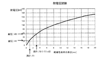
ここで、本実施形態の放射線発生装置に用いられる絶縁性板材の厚さとその耐電圧についての試験結果である図2を用いて、絶縁性板材の厚さとその耐電圧の関係について説明する。 Here, the relationship between the thickness of the insulating plate and the withstand voltage will be described with reference to FIG. 2 which is a test result of the thickness of the insulating plate and the withstand voltage used in the radiation generating apparatus of the present embodiment.
図2からわかるように、絶縁性板材の厚さが増加すれば、その耐電圧もまた増加するが、絶縁性板材の厚さとその耐電圧の間には必ずしも正比例関係があるわけではない。図2を本実施形態の放射線発生装置における絶縁性板材28、29、30にあてはめて更に詳しく説明する。絶縁性板材28、29、30の厚さをT1とすると、そのときの耐電圧はV1となる。ここで、厚さT1の3倍の厚さをT0とすると、そのときの耐電圧はV0となり、耐電圧V1を3倍した値は、耐電圧V0よりも大きいことがわかる。即ち、絶縁性板材28、29、30の各耐電圧の合計は、絶縁性板材28、29、30の各厚さを合計した厚さの絶縁性板材の耐電圧よりも大きい。よって、本実施形態のように絶縁性板材28、29、30が隙間を空けて並んで配置された場合の方が、絶縁性板材28、29、30の合計の厚さを有する絶縁性板材が配置された場合よりも、第一の窓27と第二の窓19との間の耐電圧が大きくなる。尚、配置される絶縁性板材の合計の厚さが同じで隙間の有無が異なる上記各々の場合において、外囲器12の内壁と放射線発生管14との間に充填する絶縁性流体は同じとし、第一の窓27及びその周縁部と第二の窓19及びその周縁部との間の距離も同じとする。また、上述のように第一の窓27と第二の窓19との間の耐電圧を向上させるためには、絶縁性板材28、29、30が隙間を空けて並んで配置された場合に、各絶縁性板材が耐電圧性能を保持する必要がある。
As can be seen from FIG. 2, the withstand voltage increases as the thickness of the insulating plate increases, but the thickness of the insulating plate and the withstand voltage do not necessarily have a direct proportional relationship. FIG. 2 is applied to the insulating
以下、複数枚の絶縁性板材間の隙間がどれだけあれば個々の絶縁性板材としての耐電圧性能を保持できるかについて説明する。例えば、絶縁性板材28、29を隙間なく密接して配置した場合、絶縁性板材の耐電圧は、絶縁性板材28、29の合計の厚さを有する絶縁性板材の耐電圧となる。ここで、隙間がどれだけあれば個々の絶縁性板材としての耐電圧性能を保持するかは、一般的に絶縁性板材と絶縁性板材の隙間にある部材の電子侵入長d0よりも長い隙間があれば良いことがわかっている。これは、隙間にある部材の電子侵入長d0よりも長い隙間があれば、隙間にある部材を電子が突き抜けることができないため、高電位側にある絶縁性板材は耐電圧性能を保持することができるからである。電子侵入長d0は、隙間にかかる電位差ΔV[kV]、隙間にある部材の密度ρ[g/cm3]を用いて下記式で表わされる。
Hereinafter, it will be described how the withstand voltage performance of each insulating plate can be maintained if there is a gap between the plurality of insulating plates. For example, when the insulating
電子侵入長d0[μm]=5.2×10-6×2.3×ΔV1.8/ρ
ここで、隙間に絶縁性流体である電気絶縁油(ρ=0.88[g/cm3])を充填した場合において、隙間にかかる電位差ΔVと電子侵入長d0との関係を上記式より算出し、その算出結果を表1に示す。
Electron penetration length d 0 [μm] = 5.2 × 10 −6 × 2.3 × ΔV 1.8 / ρ
Here, when the gap is filled with electrical insulating oil (ρ = 0.88 [g / cm 3 ]), which is an insulating fluid, the relationship between the potential difference ΔV applied to the gap and the electron penetration length d 0 is obtained from the above equation. Table 1 shows the calculation results.

隙間を1μmにした場合、その隙間にかかる電位差が3kv以下であれば、電子侵入長d0が1μmを超えることはない。隙間を10μmにした場合、その隙間にかかる電位差が10kv以下であれば、電子侵入長d0が10μmを超えることはない。隙間を100μmにした場合、その隙間にかかる電位差が35kv以下であれば、電子侵入長d0が100μmを超えることはない。このことから、本実施形態において、絶縁性板材が耐電圧性能を保持するには、隙間にかかる電位差ΔVを考慮して隙間の距離を決めれば良いことがわかる。例えば、後述する中点接地型の電源方式を採用した放射線発生装置11における第一の窓27と第二の窓19との間の電位差が約60kvの場合を考える。この場合、絶縁性板材を板厚1mmで耐電圧22kvのポリイミド板3枚構成で配置すれば、絶縁性板材3枚で耐電圧66kvを保持することができる。この構成にすると、仮に絶縁性板材1枚が絶縁破壊され短絡状態であったとしても絶縁性板材と絶縁性板材の隙間にかかる電位差は50kv以上かかることはない。そのため、表1より隙間の距離を156μm以上とれば良いことがわかる。尚、このときの、隙間に充填された電気絶縁油の耐電圧については安全率を高めるための要素として考えるに留めた。また、絶縁性板材と絶縁性板材の隙間にある部材は、上述した電気絶縁油に限定されるわけではない。
When the gap 1 [mu] m, a potential difference according to the gap is equal to or less than 3 kv, never electron penetration depth d 0 exceeds 1 [mu] m. If the gap 10 [mu] m, a potential difference according to the gap is equal to or less than 10kv, never electron penetration depth d 0 exceeds 10 [mu] m. If the gap 100 [mu] m, a potential difference according to the gap is equal to or less than 35kv, never electron penetration depth d 0 exceeds 100 [mu] m. From this, it can be seen that in this embodiment, in order for the insulating plate material to maintain the withstand voltage performance, the distance of the gap may be determined in consideration of the potential difference ΔV applied to the gap. For example, let us consider a case where the potential difference between the
絶縁性板材28、29、30の材料としては電気絶縁性が高く、放射線減衰量の少ない材料が良い。例えばポリイミド、セラミックス、エポキシ樹脂又はガラス等が良い。第一の窓27と第二の窓19との間の耐電圧性の確保の観点からすると、絶縁性板材28、29、30は厚さ0.01mm〜6mmであるのが好ましい。本実施形態では絶縁性板材28、29、30をポリイミド板とし、各厚さ1mmとすることができる。この場合、各厚さを合計した厚さの絶縁性板材の耐電圧に比べて耐電圧が約10kv向上できる。但し、絶縁性板材の材料はこれに限定されるわけではなく、第一の窓27と第二の窓19との間の距離、外囲器12の内壁と放射線発生管14との間に充填されている絶縁性流体13の耐電圧等によって、適宜選定する。また、絶縁性板材の材料として絶縁性流体13よりも電気絶縁性が高い材料を用いても良いし、絶縁性流体13と同じ又はそれよりも高い放射線透過率を有する材料を用いても良い。
As the material of the insulating
保持部材25は、放射線発生管14の胴部を保持するためのものである。図1では放射線発生管14が胴部の二箇所で保持部材25によって保持されているが、放射線発生管14は少なくとも胴部の一箇所以上で保持部材25によって保持されていれば良い。保持部材25の材料としては、例えば鉄、ステンレス、真鍮、銅等の導電性部材や、エンジニアリングプラスチック、セラミック等の絶縁性を有する部材が使用可能である。
The holding
第1制御電極16は、電子源15で発生した電子を引き出すためのものであり、第2制御電極17は、ターゲット18における電子の焦点径を制御するためのものである。本実施形態のように第1制御電極16と第2制御電極17を設けた場合、第1制御電極16によって形成される電界により電子源15から放出された電子束23は、第2制御電極17の電位制御により集束される。ターゲット18の電位は電子源15に対して正電位となっているため、第2制御電極17を通過した電子束23は、ターゲット18に引き寄せられてターゲット18に衝突し、放射線24を発生する。電子束23のON/OFF制御は、第1制御電極16の電圧で制御する。第1制御電極16の材料としてはステンレス、モリブデン、鉄等が使用可能である。
The
電源回路26は、放射線発生管14に接続され(配線不図示)、電子源15、第1制御電極16、第2制御電極17及びターゲット18に電気を供給するためのものであり、本実施形態では外囲器12内に配置しているが、外囲器12の外に配置しても良い。
The
人体等の放射線撮影を行う場合、ターゲット18は電子源15の電位に対して電位が+30kV〜150kV程度高くなっている。この電位差はターゲット18から発生する放射線が人体を透過し、有効に撮影に寄与するために必要な加速電位差である。人体の放射線撮影を行う際には通常X線が使用されるが、本発明はX線以外の放射線にも適用可能である。
When radiography of a human body or the like is performed, the potential of the
本実施形態の放射線発生装置11は、ターゲット18と電子源15との電位差Vを20kV〜160kVとし、ターゲット18に+V/2、電子源15に−V/2の電位を与え、保持部材25で接地した、中点接地型の電源方式を採用している。これは、絶縁性流体13の絶縁破壊距離から考えて、一般的に外囲器12が小型化できるからである。また、本実施形態は中点接地型でなくても良いが、中点接地型にするとグランドに対するターゲット18の電圧及び電子源15の電圧の絶対値を小さくすることができるため、陽極接地型等と比べて電源回路26を小規模にできる点でより好ましい。中点で接地しなくても、例えば放射線発生管14の両端から離れた位置に保持部材25を配置し、その位置で接地した場合でも陽極接地型等と比べると電源回路26を小規模にできる。
In the
上記構成の放射線発生装置11を電位差Vで駆動すると、ターゲット18、第二の窓19及び遮蔽部材20の電位は+V/2となる。これに対向する第一の窓27、外囲器12は接地電位であるため、この間に+V/2の電位差が生じる。これは10kV〜80kVという大変高い電位差である。装置の小型化の観点からすると、第一の窓27及びその周縁部と第二の窓19及びその周縁部との距離をできるだけ短くするのが良いが、この距離を短くすると放電し易くなる。また、+V/2の電位差で生じる電界は、ターゲット18、第二の窓19及び遮蔽部材20の形状により、電界集中する可能性があるため、ターゲット18の近傍は放電し易い部位となる。更に、放射線発生管14ではターゲット18を備える一端での発熱が大きい。即ちターゲット18で発生した熱が第二の窓19、遮蔽部材20へと伝わるためアノード21での発熱が大きい。例えば放射線発生装置11を150W程度の出力で駆動した場合、遮蔽部材20表面の最高温度は200℃以上になると推定される。よって、絶縁性液体のような、温度の影響で耐電圧性が低下する絶縁物では、ターゲット18の近傍は一層放電し易い部位となる。
When the
従って、本実施形態では、図1のように、第一の窓27及びその周縁部と第二の窓19及びその周縁部との間に、3枚の絶縁性板材28、29、30を、隙間を空けて並べて配置した。絶縁性板材を用いるため、温度等の影響を受けにくくなり、第一の窓27と第二の窓19との間の耐電圧が、絶縁性板材を用いない場合よりも向上する。一般に、電気絶縁油のような絶縁性液体は高い電気絶縁性と耐電圧性を有するが、絶縁性液体中に含まれている、あるいは経時劣化により生じる不純物、水分、気泡などにより、耐電圧性が低下する場合がある。そのため絶縁性板材を設けることにより、より確実に高耐電圧性を維持することができる。更に、絶縁性板材間の隙間は、第一の窓27と第二の窓19との間の耐電圧が、3枚の絶縁性板材に換えて各絶縁性板材の厚さの合計と同じ厚さを持った絶縁性板材を配置した場合に比べて大きくなる隙間とした。このため、絶縁性板材28、29、30の厚さの合計と同じ厚さを持った絶縁性板材を配置した場合よりも第一の窓27と第二の窓19との間の耐電圧が向上する。よって、第一の窓27及びその周縁部と第二の窓19及びその周縁部との距離を短くして装置を小型化しても耐電圧を確保できる。
Therefore, in this embodiment, as shown in FIG. 1, the three insulating
また、絶縁性板材3枚の合計の耐電圧と等しい1枚の絶縁性板材の板厚は、絶縁性板材3枚の合計の板厚に比べて厚い。そのため、前記1枚の絶縁性板材の放射線減衰量は、絶縁性板材3枚による放射線減衰量に比べて大きい。よって、絶縁性板材3枚構成で配置することと、第一の窓27及びその周縁部と第二の窓19及びその周縁部との距離を少なくとも前記1枚の絶縁性板材の板厚から絶縁性板材3枚の合計の板厚の差分だけ短くすることで、放射線減衰量を低減できる。更に、絶縁性板材間における絶縁性流体13の層の厚さを、安全率分薄くすることができるため、外囲器12を小型軽量化できる。
In addition, the thickness of one insulating plate equal to the total withstand voltage of the three insulating plates is thicker than the total thickness of the three insulating plates. For this reason, the radiation attenuation amount of the one insulating plate member is larger than the radiation attenuation amount of the three insulating plate members. Therefore, it arrange | positions by the structure of 3 sheets of insulating board | plate materials, and insulates the distance of the
以上より、本実施形態によれば、上記構成をとるため、装置の小型化、外囲器12と放射線発生管14との間の耐電圧の向上、放射線の減衰量の低減を実現できる。これにより、長時間安定して放射線を発生可能な信頼性の高い放射線発生装置を実現できる。
As described above, according to the present embodiment, since the above configuration is adopted, it is possible to reduce the size of the apparatus, improve the withstand voltage between the
尚、図1では、絶縁性板材28、29、30により外囲器12内を第一の窓27側と第二の窓19側に完全に仕切っているが、このような配置に限定されない。アノード21における第一の窓27に最も近い端面と、第一の窓27及びその周縁部との間で特に放電が発生し易いため、絶縁性板材28、29、30はアノード21における第一の窓27に最も近い端面に対向する領域に配置されていれば良い。
In FIG. 1, the inside of the
また、図1では、絶縁性板材28が第二の窓19及びその周縁部とは間隔を置いて配置され、絶縁性板材30が第一の窓27及びその周縁部とは間隔を置いて配置されているが、このような配置に限定されない。絶縁性板材28が第二の窓19及びその周縁部に接していても良いし、絶縁性板材30が第一の窓27及びその周縁部に接していても良い。
Further, in FIG. 1, the insulating
更に、アノード21の形状は図1の形状に限定されるわけではない。図1のように遮蔽部材20の端面の一部が第二の窓19よりも第一の窓27側に突出していなくても良い。例えば遮蔽部材20の端面と第二の窓19の第一の窓27側の面が面一になっている場合でも本発明を適用することができる。
Furthermore, the shape of the
〔第2の実施形態〕
図3は本実施形態の放射線発生装置11の断面模式図である。
[Second Embodiment]
FIG. 3 is a schematic cross-sectional view of the
本実施形態の放射線発生装置(透過型放射線源)11は、図3のように、絶縁性流体13で充填された外囲器12において第一の窓27と第二の窓19との間に厚さの異なる2枚の絶縁性板材28、31を配置している点が第1の実施形態と異なる。この点を除いては、第1の実施形態と同じであるため、絶縁性板材28、31以外の各部材の説明、及び放射線発生装置11の構成についての説明は省略する。
As shown in FIG. 3, the radiation generator (transmission type radiation source) 11 of the present embodiment is provided between the
本実施形態においては、2枚の絶縁性板材28、31が第一の窓27及びその周縁部と第二の窓19及びその周縁部との間に隙間を空けて並んで配置されている。隙間にも外囲器12の内壁と放射線発生管14との間に充填された絶縁性流体13が充填されている。このため、放射線24は絶縁性板材28、31を通過し、第一の窓27から外囲器12の外部に放出される。絶縁性板材28、31にそれぞれ絶縁性流体13を循環させるための孔を設け、隙間の絶縁性流体13を循環させても良い。
In the present embodiment, the two insulating
ここで、本実施形態の放射線発生装置に用いられる絶縁性板材の厚さとその耐電圧についての試験結果である図4を用いて、絶縁性板材の厚さとその耐電圧の関係について説明する。 Here, the relationship between the thickness of the insulating plate and the withstand voltage will be described with reference to FIG. 4 which is a test result of the thickness of the insulating plate and the withstand voltage used in the radiation generating apparatus of the present embodiment.
図4からわかるように、絶縁性板材の厚さが増加すれば、その耐電圧もまた増加するが、絶縁性板材の厚さとその耐電圧の間には必ずしも正比例関係があるわけではない。図4を本実施形態の放射線発生装置における絶縁性板材28、31にあてはめて更に詳しく説明する。絶縁性板材28の厚さをT1とすると、そのときの耐電圧はV1となり、絶縁性板材31の厚さをT2とすると、そのときの耐電圧はV2となる。ここで、厚さT1と厚さT2の合計の厚さをT0とすると、そのときの耐電圧はV0となり、耐電圧V1と耐電圧V2を合計した値は、耐電圧V0よりも大きいことがわかる。即ち、絶縁性板材28の耐電圧と絶縁性板材31の耐電圧の合計は、絶縁性板材28の厚さと絶縁性板材31の厚さを合計した厚さの絶縁性板材の耐電圧よりも大きい。よって、本実施形態のように絶縁性板材28、31が隙間を空けて並んで配置された場合の方が、絶縁性板材28、31の合計の厚さを有する絶縁性板材が配置された場合よりも、第一の窓27と第二の窓19との間の耐電圧が大きくなる。絶縁性板材28と絶縁性板材31の隙間の距離については、第1の実施形態と同様にして決定する。
As can be seen from FIG. 4, as the thickness of the insulating plate increases, the withstand voltage also increases, but the thickness of the insulating plate and the withstand voltage do not necessarily have a direct proportional relationship. FIG. 4 is applied to the insulating
絶縁性板材28、31の材料は、電気絶縁性が高く、放射線減衰量の少ない材料が良く、第1の実施形態で用いられる絶縁性板材と同じ材料を用いることができる。例えばポリイミド、セラミックス、エポキシ樹脂又はガラス等が良い。本実施形態では絶縁性板材28を厚さ1mm程度のポリイミド板、絶縁性板材31を厚さ2mm程度のポリイミド板とすることができる。
The material of the insulating
本実施形態では、図3のように、第一の窓27及びその周縁部と第二の窓19及びその周縁部との間に、2枚の絶縁性板材28、31を、隙間を空けて並べて配置した。更に、絶縁性板材間の隙間は、第一の窓27と第二の窓19との間の耐電圧が、2枚の絶縁性板材に換えて各絶縁性板材の厚さの合計と同じ厚さを持った絶縁性板材を配置した場合に比べて大きくなる隙間とした。このため、第1の実施形態と同様に、温度等の影響を受けにくくなり、第一の窓27と第二の窓19との間の耐電圧が向上する。
In the present embodiment, as shown in FIG. 3, two insulating
また、絶縁性板材2枚構成で配置することと、第一の窓27及びその周縁部と第二の窓19及びその周縁部との距離を少なくとも前記1枚の絶縁性板材の板厚から絶縁性板材2枚の合計の板厚の差分だけ短くすることで、放射線減衰量を低減できる。更に、絶縁性板材間における絶縁性流体13の層の厚さを、安全率分薄くすることができるため、外囲器12を小型軽量化できる。
Further, the two insulating plate members are arranged, and the distance between the
以上より、本実施形態によれば、上記構成をとるため、第1の実施形態と同様の効果が得られる。 As described above, according to the present embodiment, since the above configuration is adopted, the same effect as that of the first embodiment can be obtained.
尚、絶縁性板材28、31は放射線発生管14における第一の窓27に最も近い端面に対向する領域に配置されていれば良い。また、絶縁性板材28は第二の窓19及びその周縁部に接していても良いし、絶縁性板材31は第一の窓27及びその周縁部に接していても良い。
The insulating
〔第3の実施形態〕
図5は本実施形態の放射線発生装置11の断面模式図である。
[Third Embodiment]
FIG. 5 is a schematic cross-sectional view of the
本実施形態の放射線発生装置(透過型放射線源)11は、図5のように、絶縁性流体13として気体を用いた点が第1の実施形態と異なる。この点を除いては、第1の実施形態と同じであるため、絶縁性流体13以外の各部材の説明、及び放射線発生装置11の構成についての説明は省略する。
The radiation generator (transmission radiation source) 11 of this embodiment is different from the first embodiment in that gas is used as the insulating
気体の絶縁性流体13としては、鉱油系絶縁油に匹敵した絶縁性能を持つ、六フッ化イオウ等を用いることができる。
As the gaseous insulating
以上より、本実施形態によれば、上記構成をとるため、第1の実施形態と同様の効果が得られる。更に、絶縁性流体13として気体を用いることで液体よりも装置の重量を軽くすることができるので、第1の実施形態よりも放射線発生装置11を小型軽量化できる。
As described above, according to the present embodiment, since the above configuration is adopted, the same effect as that of the first embodiment can be obtained. Furthermore, since the weight of the apparatus can be made lighter than the liquid by using a gas as the insulating
〔第4の実施形態〕
図6は本実施形態の放射線発生装置11の断面模式図である。
[Fourth Embodiment]
FIG. 6 is a schematic cross-sectional view of the
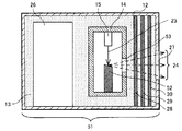
本実施形態の放射線発生装置(反射型放射線源)51は、図6のように、反射型の放射線発生管14を用いている点が第1〜第3の実施形態と異なる。この点を除いては、第1の実施形態と同じであるため、反射型ターゲット52、第二の窓53、放射線発生管14以外の各部材の説明は省略する。
The radiation generating apparatus (reflective radiation source) 51 of this embodiment is different from the first to third embodiments in that a reflective
本実施形態の放射線発生装置51は、外囲器12、絶縁性流体13、放射線発生管14、電子源15、電源回路26、第一の窓27、絶縁性板材28、29、30、反射型ターゲット52、第二の窓53を有している。
The
反射型ターゲット52は、第二の窓53と間隔を置いて、第二の窓53と対向して配置されている。放射線発生管14は、電子源15から放出された電子束23を反射型ターゲット52に衝突させ、放射線24を発生させる真空容器である。放射線24は、放射線発生管14の一部である、第二の窓53を通った後、第一の窓27から外囲器12の外部に放出される。
The
本実施形態においても、3枚の絶縁性板材28、29、30が第一の窓27及びその周縁部と第二の窓19及びその周縁部との間に隙間を空けて並んで配置されている。隙間にも外囲器12の内壁と放射線発生管14との間に充填された絶縁性流体13が充填されている。絶縁性板材と絶縁性板材の隙間の距離については、第1の実施形態と同様にして決定する。このため、放射線24は絶縁性板材28、29、30を通過し、第一の窓27から外囲器12の外部に放出される。絶縁性板材28、29、30にそれぞれ絶縁性流体13を循環させるための孔を設け、隙間の絶縁性流体13を循環させても良い。
Also in the present embodiment, the three insulating
以上より、本実施形態によれば、上記構成をとるため、第1の実施形態と同様の効果が得られる。 As described above, according to the present embodiment, since the above configuration is adopted, the same effect as that of the first embodiment can be obtained.
尚、絶縁性板材28、29、30は放射線発生管14における第一の窓27に最も近い端面に対向する領域に配置されていれば良い。また、絶縁性板材28は第二の窓53及びその周縁部に接していても良いし、絶縁性板材30は第一の窓27及びその周縁部に接していても良い。
The insulating
〔第5の実施形態〕
図7を用いて本発明の放射線発生装置を用いた放射線撮影装置について説明する。図7は本実施形態の放射線撮影装置の構成図である。この放射線撮影装置は放射線発生装置11、放射線検出器61、放射線検出信号処理部62、放射線撮影装置制御部63、電子源駆動部64、電子源ヒーター制御部65、制御電極電圧制御部66及びターゲット電圧制御部67を備えている。放射線発生装置11としては例えば第1〜第4の実施形態の放射線発生装置が好適に用いられる。
[Fifth Embodiment]
A radiation imaging apparatus using the radiation generation apparatus of the present invention will be described with reference to FIG. FIG. 7 is a configuration diagram of the radiation imaging apparatus of the present embodiment. The radiation imaging apparatus includes a
放射線検出器61は、放射線検出信号処理部62を介して放射線撮影装置制御部63に接続されている。放射線撮影装置制御部63の出力信号は、電子源駆動部64、電子源ヒーター制御部65、制御電極電圧制御部66、ターゲット電圧制御部67を介して放射線発生装置11の各端子に接続されている。
The
放射線発生装置11で放射線を発生させると、大気中に放出された放射線は、被検体(不図示)を透過して放射線検出器61に検出され、被検体の放射線透過画像が得られる。得られた放射線透過画像は表示部(不図示)に表示させることができる。
When radiation is generated by the
以上より、本実施形態によれば、第1〜第4の実施形態の効果を奏する放射線発生装置を用いるため、装置の小型化、外囲器と放射線発生管との間の耐電圧の向上、放射線の減衰量の低減を実現した放射線撮影装置を実現できる。 As described above, according to the present embodiment, since the radiation generating apparatus having the effects of the first to fourth embodiments is used, the apparatus is downsized, and the withstand voltage between the envelope and the radiation generating tube is improved. A radiographic apparatus that can reduce the attenuation of radiation can be realized.
11:放射線発生装置(透過型放射線源)、12:外囲器、13:絶縁性流体、14:放射線発生管、15:電子源、16:第1制御電極、17:第2制御電極、18:透過型ターゲット、19:ターゲット基板(第二の窓)、20:遮蔽部材、21:アノード、22:カソード支持部材、23:電子束、24:放射線、25:保持部材、26:電源回路、27:第一の窓、28〜31:絶縁性板材、51:放射線発生装置(反射型放射線源)、52:反射型ターゲット、53:第二の窓、61:放射線検出器 11: Radiation generation device (transmission type radiation source), 12: Envelope, 13: Insulating fluid, 14: Radiation generation tube, 15: Electron source, 16: First control electrode, 17: Second control electrode, 18 : Transmission target, 19: Target substrate (second window), 20: Shielding member, 21: Anode, 22: Cathode support member, 23: Electron bundle, 24: Radiation, 25: Holding member, 26: Power supply circuit, 27: First window, 28-31: Insulating plate material, 51: Radiation generator (reflective radiation source), 52: Reflective target, 53: Second window, 61: Radiation detector
Claims (6)
前記外囲器内に収納され、前記第一の窓と対向する位置に放射線を透過する第二の窓を有する放射線発生管と、
前記外囲器の内壁と前記放射線発生管との間に配置された絶縁性流体と、
を備える放射線発生装置であって、
前記第一の窓及びその周縁部と前記第二の窓及びその周縁部との間に、複数枚の絶縁性板材が隙間を空けて重なって配置されていることを特徴とする放射線発生装置。 An envelope having a first window that transmits radiation;
A radiation generating tube that is housed in the envelope and has a second window that transmits radiation at a position facing the first window;
An insulating fluid disposed between the inner wall of the envelope and the radiation generating tube;
A radiation generator comprising:
A radiation generating apparatus, wherein a plurality of insulating plate members are arranged with a gap between the first window and the peripheral edge thereof and the second window and the peripheral edge thereof.
前記放射線発生装置から放出され被検体を透過した放射線を検出する放射線検出器と、
前記放射線発生装置と前記放射線検出器とを制御する制御手段と、を有することを特徴とする放射線撮影装置。 The radiation generator according to any one of claims 1 to 5 ,
A radiation detector that detects radiation emitted from the radiation generator and transmitted through the subject;
A radiation imaging apparatus comprising: a control unit that controls the radiation generation apparatus and the radiation detector .
Priority Applications (2)
| Application Number | Priority Date | Filing Date | Title |
|---|---|---|---|
| JP2011169860A JP5713832B2 (en) | 2011-08-03 | 2011-08-03 | Radiation generator and radiation imaging apparatus using the same |
| US13/539,871 US9058958B2 (en) | 2011-08-03 | 2012-07-02 | Radiation generating apparatus and radiation imaging apparatus |
Applications Claiming Priority (1)
| Application Number | Priority Date | Filing Date | Title |
|---|---|---|---|
| JP2011169860A JP5713832B2 (en) | 2011-08-03 | 2011-08-03 | Radiation generator and radiation imaging apparatus using the same |
Publications (3)
| Publication Number | Publication Date |
|---|---|
| JP2013033681A JP2013033681A (en) | 2013-02-14 |
| JP2013033681A5 JP2013033681A5 (en) | 2014-07-24 |
| JP5713832B2 true JP5713832B2 (en) | 2015-05-07 |
Family
ID=47626952
Family Applications (1)
| Application Number | Title | Priority Date | Filing Date |
|---|---|---|---|
| JP2011169860A Expired - Fee Related JP5713832B2 (en) | 2011-08-03 | 2011-08-03 | Radiation generator and radiation imaging apparatus using the same |
Country Status (2)
| Country | Link |
|---|---|
| US (1) | US9058958B2 (en) |
| JP (1) | JP5713832B2 (en) |
Families Citing this family (24)
| Publication number | Priority date | Publication date | Assignee | Title |
|---|---|---|---|---|
| WO2012077445A1 (en) | 2010-12-10 | 2012-06-14 | Canon Kabushiki Kaisha | Radiation generating apparatus and radiation imaging apparatus |
| JP5455880B2 (en) | 2010-12-10 | 2014-03-26 | キヤノン株式会社 | Radiation generating tube, radiation generating apparatus and radiographic apparatus |
| JP5825892B2 (en) * | 2011-07-11 | 2015-12-02 | キヤノン株式会社 | Radiation generator and radiation imaging apparatus using the same |
| JP6039282B2 (en) | 2011-08-05 | 2016-12-07 | キヤノン株式会社 | Radiation generator and radiation imaging apparatus |
| WO2013021794A1 (en) | 2011-08-05 | 2013-02-14 | Canon Kabushiki Kaisha | Radiation generating apparatus and radiation imaging apparatus |
| JP5984367B2 (en) | 2011-12-02 | 2016-09-06 | キヤノン株式会社 | Radiation generator and radiation imaging system using the same |
| JP5540033B2 (en) * | 2012-03-05 | 2014-07-02 | 双葉電子工業株式会社 | X-ray tube |
| JP5763032B2 (en) * | 2012-10-02 | 2015-08-12 | 双葉電子工業株式会社 | X-ray tube |
| JP6230389B2 (en) | 2013-06-05 | 2017-11-15 | キヤノン株式会社 | X-ray generator tube, X-ray generator and X-ray imaging system using the same |
| JP6327802B2 (en) * | 2013-06-12 | 2018-05-23 | キヤノン株式会社 | Radiation generating tube, radiation generating apparatus and radiation imaging system using the same |
| JP6188470B2 (en) * | 2013-07-24 | 2017-08-30 | キヤノン株式会社 | Radiation generator and radiation imaging system using the same |
| JP6326758B2 (en) * | 2013-10-16 | 2018-05-23 | 株式会社島津製作所 | X-ray generator |
| JP6272043B2 (en) * | 2014-01-16 | 2018-01-31 | キヤノン株式会社 | X-ray generator tube, X-ray generator using the same, and X-ray imaging system |
| JP6598538B2 (en) | 2014-07-18 | 2019-10-30 | キヤノン株式会社 | Anode, X-ray generator tube, X-ray generator, X-ray imaging system using the same |
| JP6441015B2 (en) * | 2014-10-06 | 2018-12-19 | キヤノンメディカルシステムズ株式会社 | X-ray diagnostic apparatus and X-ray tube control method |
| KR101864214B1 (en) * | 2014-11-21 | 2018-06-05 | 한국전자통신연구원 | Micro x-ray tube |
| US9786466B2 (en) * | 2014-11-21 | 2017-10-10 | Electronics And Telecommunications Research Institute | Micro X-ray tube |
| DE102015213810B4 (en) * | 2015-07-22 | 2021-11-25 | Siemens Healthcare Gmbh | High voltage feed for an X-ray tube |
| JP6573380B2 (en) * | 2015-07-27 | 2019-09-11 | キヤノン株式会社 | X-ray generator and X-ray imaging system |
| DE102016222365B3 (en) * | 2016-11-15 | 2018-04-05 | Siemens Healthcare Gmbh | A method, computer program product, computer readable medium and apparatus for generating x-ray pulses in x-ray imaging |
| KR101966794B1 (en) * | 2017-07-12 | 2019-08-27 | (주)선재하이테크 | X-ray tube for improving electron focusing |
| EP3905299A4 (en) * | 2018-12-28 | 2022-04-06 | Canon Anelva Corporation | Electron gun, x-ray generation device, and x-ray imaging device |
| US11315751B2 (en) * | 2019-04-25 | 2022-04-26 | The Boeing Company | Electromagnetic X-ray control |
| EP3793330A1 (en) * | 2019-09-12 | 2021-03-17 | Siemens Healthcare GmbH | X-ray source |
Family Cites Families (11)
| Publication number | Priority date | Publication date | Assignee | Title |
|---|---|---|---|---|
| JPS6166399A (en) | 1984-09-07 | 1986-04-05 | Hitachi Ltd | Rotary anode x-ray tube device |
| FR2700657B1 (en) * | 1993-01-15 | 1995-02-17 | Gen Electric Cgr | X-ray unit. |
| JPH1164599A (en) * | 1997-08-25 | 1999-03-05 | Shimadzu Corp | X-ray radiating device |
| JP2003290204A (en) * | 2002-04-02 | 2003-10-14 | Mitsubishi Heavy Ind Ltd | Multiple radiation source x-ray ct system |
| JP2007250328A (en) * | 2006-03-15 | 2007-09-27 | Toshiba Corp | X-ray tube and x-ray tube device |
| JP4908341B2 (en) * | 2006-09-29 | 2012-04-04 | 株式会社東芝 | Rotating anode type X-ray tube device |
| US7684544B2 (en) * | 2006-12-14 | 2010-03-23 | Wilson Kevin S | Portable digital radiographic devices |
| US7949099B2 (en) * | 2007-07-05 | 2011-05-24 | Newton Scientific Inc. | Compact high voltage X-ray source system and method for X-ray inspection applications |
| JP5582719B2 (en) * | 2009-04-28 | 2014-09-03 | 株式会社東芝 | Rotating anode type X-ray tube device |
| JP5416006B2 (en) | 2010-03-23 | 2014-02-12 | キヤノン株式会社 | X-ray generator and control method thereof |
| JP5661432B2 (en) | 2010-11-17 | 2015-01-28 | キヤノン株式会社 | X-ray generator |
-
2011
- 2011-08-03 JP JP2011169860A patent/JP5713832B2/en not_active Expired - Fee Related
-
2012
- 2012-07-02 US US13/539,871 patent/US9058958B2/en not_active Expired - Fee Related
Also Published As
| Publication number | Publication date |
|---|---|
| US9058958B2 (en) | 2015-06-16 |
| US20130034207A1 (en) | 2013-02-07 |
| JP2013033681A (en) | 2013-02-14 |
Similar Documents
| Publication | Publication Date | Title |
|---|---|---|
| JP5713832B2 (en) | Radiation generator and radiation imaging apparatus using the same | |
| JP5825892B2 (en) | Radiation generator and radiation imaging apparatus using the same | |
| JP5796990B2 (en) | X-ray generator and X-ray imaging apparatus using the same | |
| KR101563521B1 (en) | Radiation generating apparatus and radiation imaging apparatus | |
| US9281155B2 (en) | Radiation generating apparatus and radiation imaging apparatus | |
| JP5791401B2 (en) | Radiation generator and radiation imaging apparatus using the same | |
| US9076627B2 (en) | Radiation generating apparatus and radiation imaging apparatus using the same | |
| US9373478B2 (en) | Radiation generating apparatus and radiation imaging apparatus | |
| KR20140043146A (en) | Radiation generating apparatus and radiation imaging apparatus | |
| WO2013081179A1 (en) | Radiation generating apparatus and radiographing system using the same | |
| JP2014149932A (en) | Radiation generator and radiographic system | |
| JP2015076359A (en) | X-ray tube apparatus | |
| JP6021338B2 (en) | Radiation generator and radiation imaging apparatus using the same | |
| JP5449118B2 (en) | Transmission type radiation tube, radiation generator, and radiation imaging apparatus | |
| JP2015090840A (en) | Radiation generator and radiography system | |
| JP2006024480A (en) | X-ray tube, x-ray generating device, and x-ray inspection device | |
| JP2016131141A (en) | X-ray tube assembly |
Legal Events
| Date | Code | Title | Description |
|---|---|---|---|
| A521 | Request for written amendment filed |
Free format text: JAPANESE INTERMEDIATE CODE: A523 Effective date: 20140606 |
|
| A621 | Written request for application examination |
Free format text: JAPANESE INTERMEDIATE CODE: A621 Effective date: 20140606 |
|
| A977 | Report on retrieval |
Free format text: JAPANESE INTERMEDIATE CODE: A971007 Effective date: 20150121 |
|
| TRDD | Decision of grant or rejection written | ||
| A01 | Written decision to grant a patent or to grant a registration (utility model) |
Free format text: JAPANESE INTERMEDIATE CODE: A01 Effective date: 20150210 |
|
| A61 | First payment of annual fees (during grant procedure) |
Free format text: JAPANESE INTERMEDIATE CODE: A61 Effective date: 20150310 |
|
| R151 | Written notification of patent or utility model registration |
Ref document number: 5713832 Country of ref document: JP Free format text: JAPANESE INTERMEDIATE CODE: R151 |
|
| LAPS | Cancellation because of no payment of annual fees |