EP3793330A1 - X-ray source - Google Patents
X-ray source Download PDFInfo
- Publication number
- EP3793330A1 EP3793330A1 EP19196954.2A EP19196954A EP3793330A1 EP 3793330 A1 EP3793330 A1 EP 3793330A1 EP 19196954 A EP19196954 A EP 19196954A EP 3793330 A1 EP3793330 A1 EP 3793330A1
- Authority
- EP
- European Patent Office
- Prior art keywords
- ray tube
- ray
- compressor
- housing
- emitter
- Prior art date
- Legal status (The legal status is an assumption and is not a legal conclusion. Google has not performed a legal analysis and makes no representation as to the accuracy of the status listed.)
- Pending
Links
- 238000001816 cooling Methods 0.000 claims abstract description 69
- 239000002826 coolant Substances 0.000 claims abstract description 56
- 239000007788 liquid Substances 0.000 description 14
- 230000000875 corresponding effect Effects 0.000 description 6
- 230000006870 function Effects 0.000 description 5
- 239000004696 Poly ether ether ketone Substances 0.000 description 4
- 239000000463 material Substances 0.000 description 4
- 229910052751 metal Inorganic materials 0.000 description 4
- 239000002184 metal Substances 0.000 description 4
- 229920002530 polyetherether ketone Polymers 0.000 description 4
- 230000001133 acceleration Effects 0.000 description 3
- 229910052782 aluminium Inorganic materials 0.000 description 3
- XAGFODPZIPBFFR-UHFFFAOYSA-N aluminium Chemical compound [Al] XAGFODPZIPBFFR-UHFFFAOYSA-N 0.000 description 3
- 230000020169 heat generation Effects 0.000 description 3
- 238000003384 imaging method Methods 0.000 description 3
- 239000004033 plastic Substances 0.000 description 3
- IJGRMHOSHXDMSA-UHFFFAOYSA-N Atomic nitrogen Chemical compound N#N IJGRMHOSHXDMSA-UHFFFAOYSA-N 0.000 description 2
- CURLTUGMZLYLDI-UHFFFAOYSA-N Carbon dioxide Chemical compound O=C=O CURLTUGMZLYLDI-UHFFFAOYSA-N 0.000 description 2
- RYGMFSIKBFXOCR-UHFFFAOYSA-N Copper Chemical compound [Cu] RYGMFSIKBFXOCR-UHFFFAOYSA-N 0.000 description 2
- 229910018503 SF6 Inorganic materials 0.000 description 2
- 230000005540 biological transmission Effects 0.000 description 2
- 239000010949 copper Substances 0.000 description 2
- 229910052802 copper Inorganic materials 0.000 description 2
- 239000000835 fiber Substances 0.000 description 2
- 239000011521 glass Substances 0.000 description 2
- 238000010438 heat treatment Methods 0.000 description 2
- 230000003068 static effect Effects 0.000 description 2
- SFZCNBIFKDRMGX-UHFFFAOYSA-N sulfur hexafluoride Chemical group FS(F)(F)(F)(F)F SFZCNBIFKDRMGX-UHFFFAOYSA-N 0.000 description 2
- 229960000909 sulfur hexafluoride Drugs 0.000 description 2
- ZOKXTWBITQBERF-UHFFFAOYSA-N Molybdenum Chemical compound [Mo] ZOKXTWBITQBERF-UHFFFAOYSA-N 0.000 description 1
- 229910000831 Steel Inorganic materials 0.000 description 1
- RTAQQCXQSZGOHL-UHFFFAOYSA-N Titanium Chemical compound [Ti] RTAQQCXQSZGOHL-UHFFFAOYSA-N 0.000 description 1
- 239000003570 air Substances 0.000 description 1
- 239000000956 alloy Substances 0.000 description 1
- 229910045601 alloy Inorganic materials 0.000 description 1
- QVGXLLKOCUKJST-UHFFFAOYSA-N atomic oxygen Chemical compound [O] QVGXLLKOCUKJST-UHFFFAOYSA-N 0.000 description 1
- JUPQTSLXMOCDHR-UHFFFAOYSA-N benzene-1,4-diol;bis(4-fluorophenyl)methanone Chemical compound OC1=CC=C(O)C=C1.C1=CC(F)=CC=C1C(=O)C1=CC=C(F)C=C1 JUPQTSLXMOCDHR-UHFFFAOYSA-N 0.000 description 1
- 229910052790 beryllium Inorganic materials 0.000 description 1
- ATBAMAFKBVZNFJ-UHFFFAOYSA-N beryllium atom Chemical compound [Be] ATBAMAFKBVZNFJ-UHFFFAOYSA-N 0.000 description 1
- 229910002092 carbon dioxide Inorganic materials 0.000 description 1
- 239000001569 carbon dioxide Substances 0.000 description 1
- 238000010276 construction Methods 0.000 description 1
- 230000002596 correlated effect Effects 0.000 description 1
- 230000008878 coupling Effects 0.000 description 1
- 238000010168 coupling process Methods 0.000 description 1
- 238000005859 coupling reaction Methods 0.000 description 1
- 230000001419 dependent effect Effects 0.000 description 1
- 230000005669 field effect Effects 0.000 description 1
- 238000002594 fluoroscopy Methods 0.000 description 1
- PCHJSUWPFVWCPO-UHFFFAOYSA-N gold Chemical compound [Au] PCHJSUWPFVWCPO-UHFFFAOYSA-N 0.000 description 1
- 229910052737 gold Inorganic materials 0.000 description 1
- 239000010931 gold Substances 0.000 description 1
- 230000017525 heat dissipation Effects 0.000 description 1
- 238000009413 insulation Methods 0.000 description 1
- 239000000203 mixture Substances 0.000 description 1
- 229910052750 molybdenum Inorganic materials 0.000 description 1
- 239000011733 molybdenum Substances 0.000 description 1
- 229910052754 neon Inorganic materials 0.000 description 1
- GKAOGPIIYCISHV-UHFFFAOYSA-N neon atom Chemical compound [Ne] GKAOGPIIYCISHV-UHFFFAOYSA-N 0.000 description 1
- 229910052757 nitrogen Inorganic materials 0.000 description 1
- 229910052760 oxygen Inorganic materials 0.000 description 1
- 239000001301 oxygen Substances 0.000 description 1
- 230000005855 radiation Effects 0.000 description 1
- 229910052702 rhenium Inorganic materials 0.000 description 1
- WUAPFZMCVAUBPE-UHFFFAOYSA-N rhenium atom Chemical compound [Re] WUAPFZMCVAUBPE-UHFFFAOYSA-N 0.000 description 1
- 229910052703 rhodium Inorganic materials 0.000 description 1
- 239000010948 rhodium Substances 0.000 description 1
- MHOVAHRLVXNVSD-UHFFFAOYSA-N rhodium atom Chemical compound [Rh] MHOVAHRLVXNVSD-UHFFFAOYSA-N 0.000 description 1
- 239000010959 steel Substances 0.000 description 1
- 238000004154 testing of material Methods 0.000 description 1
- 229920001169 thermoplastic Polymers 0.000 description 1
- 239000010936 titanium Substances 0.000 description 1
- 229910052719 titanium Inorganic materials 0.000 description 1
- WFKWXMTUELFFGS-UHFFFAOYSA-N tungsten Chemical compound [W] WFKWXMTUELFFGS-UHFFFAOYSA-N 0.000 description 1
- 229910052721 tungsten Inorganic materials 0.000 description 1
- 239000010937 tungsten Substances 0.000 description 1
Images


Classifications
-
- H—ELECTRICITY
- H01—ELECTRIC ELEMENTS
- H01J—ELECTRIC DISCHARGE TUBES OR DISCHARGE LAMPS
- H01J35/00—X-ray tubes
- H01J35/02—Details
- H01J35/04—Electrodes ; Mutual position thereof; Constructional adaptations therefor
- H01J35/08—Anodes; Anti cathodes
- H01J35/10—Rotary anodes; Arrangements for rotating anodes; Cooling rotary anodes
- H01J35/105—Cooling of rotating anodes, e.g. heat emitting layers or structures
- H01J35/106—Active cooling, e.g. fluid flow, heat pipes
-
- A—HUMAN NECESSITIES
- A61—MEDICAL OR VETERINARY SCIENCE; HYGIENE
- A61B—DIAGNOSIS; SURGERY; IDENTIFICATION
- A61B6/00—Apparatus for radiation diagnosis, e.g. combined with radiation therapy equipment
- A61B6/04—Positioning of patients; Tiltable beds or the like
- A61B6/0407—Supports, e.g. tables or beds, for the body or parts of the body
-
- A—HUMAN NECESSITIES
- A61—MEDICAL OR VETERINARY SCIENCE; HYGIENE
- A61B—DIAGNOSIS; SURGERY; IDENTIFICATION
- A61B6/00—Apparatus for radiation diagnosis, e.g. combined with radiation therapy equipment
- A61B6/42—Apparatus for radiation diagnosis, e.g. combined with radiation therapy equipment with arrangements for detecting radiation specially adapted for radiation diagnosis
- A61B6/4208—Apparatus for radiation diagnosis, e.g. combined with radiation therapy equipment with arrangements for detecting radiation specially adapted for radiation diagnosis characterised by using a particular type of detector
-
- A—HUMAN NECESSITIES
- A61—MEDICAL OR VETERINARY SCIENCE; HYGIENE
- A61B—DIAGNOSIS; SURGERY; IDENTIFICATION
- A61B6/00—Apparatus for radiation diagnosis, e.g. combined with radiation therapy equipment
- A61B6/44—Constructional features of apparatus for radiation diagnosis
-
- A—HUMAN NECESSITIES
- A61—MEDICAL OR VETERINARY SCIENCE; HYGIENE
- A61B—DIAGNOSIS; SURGERY; IDENTIFICATION
- A61B6/00—Apparatus for radiation diagnosis, e.g. combined with radiation therapy equipment
- A61B6/44—Constructional features of apparatus for radiation diagnosis
- A61B6/4488—Means for cooling
-
- G—PHYSICS
- G01—MEASURING; TESTING
- G01N—INVESTIGATING OR ANALYSING MATERIALS BY DETERMINING THEIR CHEMICAL OR PHYSICAL PROPERTIES
- G01N23/00—Investigating or analysing materials by the use of wave or particle radiation, e.g. X-rays or neutrons, not covered by groups G01N3/00 – G01N17/00, G01N21/00 or G01N22/00
- G01N23/02—Investigating or analysing materials by the use of wave or particle radiation, e.g. X-rays or neutrons, not covered by groups G01N3/00 – G01N17/00, G01N21/00 or G01N22/00 by transmitting the radiation through the material
- G01N23/04—Investigating or analysing materials by the use of wave or particle radiation, e.g. X-rays or neutrons, not covered by groups G01N3/00 – G01N17/00, G01N21/00 or G01N22/00 by transmitting the radiation through the material and forming images of the material
-
- H—ELECTRICITY
- H01—ELECTRIC ELEMENTS
- H01J—ELECTRIC DISCHARGE TUBES OR DISCHARGE LAMPS
- H01J35/00—X-ray tubes
- H01J35/02—Details
- H01J35/16—Vessels; Containers; Shields associated therewith
- H01J35/18—Windows
-
- H—ELECTRICITY
- H05—ELECTRIC TECHNIQUES NOT OTHERWISE PROVIDED FOR
- H05G—X-RAY TECHNIQUE
- H05G1/00—X-ray apparatus involving X-ray tubes; Circuits therefor
- H05G1/02—Constructional details
- H05G1/025—Means for cooling the X-ray tube or the generator
-
- A—HUMAN NECESSITIES
- A61—MEDICAL OR VETERINARY SCIENCE; HYGIENE
- A61B—DIAGNOSIS; SURGERY; IDENTIFICATION
- A61B6/00—Apparatus for radiation diagnosis, e.g. combined with radiation therapy equipment
- A61B6/02—Devices for diagnosis sequentially in different planes; Stereoscopic radiation diagnosis
- A61B6/03—Computerised tomographs
- A61B6/032—Transmission computed tomography [CT]
- A61B6/035—Mechanical aspects of CT
-
- H—ELECTRICITY
- H01—ELECTRIC ELEMENTS
- H01J—ELECTRIC DISCHARGE TUBES OR DISCHARGE LAMPS
- H01J2235/00—X-ray tubes
- H01J2235/12—Cooling
- H01J2235/1216—Cooling of the vessel
-
- H—ELECTRICITY
- H01—ELECTRIC ELEMENTS
- H01J—ELECTRIC DISCHARGE TUBES OR DISCHARGE LAMPS
- H01J2235/00—X-ray tubes
- H01J2235/12—Cooling
- H01J2235/1225—Cooling characterised by method
- H01J2235/1262—Circulating fluids
- H01J2235/127—Control of flow
-
- H—ELECTRICITY
- H01—ELECTRIC ELEMENTS
- H01J—ELECTRIC DISCHARGE TUBES OR DISCHARGE LAMPS
- H01J2235/00—X-ray tubes
- H01J2235/12—Cooling
- H01J2235/1225—Cooling characterised by method
- H01J2235/1262—Circulating fluids
- H01J2235/1283—Circulating fluids in conjunction with extended surfaces (e.g. fins or ridges)
Definitions
- the invention relates to an X-ray source and a computer tomograph.
- An x-ray emitter usually has an x-ray tube for generating x-rays, for which purpose the x-ray tube in particular is cooled.
- a liquid cooling medium in particular oil, is typically used to cool the X-ray tube.
- the X-ray tube can be actively or passively cooled with the liquid cooling medium. In the case of passive cooling with the liquid cooling medium, the X-ray tube is cooled in particular by means of convection. In the case of active cooling with the liquid cooling medium, a cooled liquid cooling medium is typically fed to the X-ray tube and a heated liquid cooling medium is removed.
- the X-ray emitter For active cooling with the liquid cooling medium, the X-ray emitter typically requires a heat exchanger to transfer thermal energy.
- a heat exchanger In addition to the heat exchanger, such an x-ray emitter typically has hoses and corresponding couplings, as a result of which the complexity and / or weight of the x-ray emitter is usually significantly increased.
- an X-ray emitter in which the evacuated X-ray tube housing has a structure on one end face which form channels for a liquid or a gaseous cooling medium.
- An anode is arranged on the inner surface of this structure in such a way that the rear side of the anode is cooled by the flowing cooling medium.
- the U.S. 4,355,410 , the U.S. 4,884,292 and the DE 698 25 248 T2 each describe an X-ray tube housing in which an X-ray tube and a fan are arranged. Of the The fan creates a flow of air, which cools the X-ray tube during operation.
- the evacuated X-ray tube housing of the X-ray tube has cooling ribs on its outer circumference to improve air cooling.
- an X-ray emitter which comprises an X-ray emitter housing in which an X-ray tube and a fan are arranged. During operation, a fan creates an air flow in the X-ray tube housing, which cools the X-ray tube from the outside.
- the gaseous cooling medium e.g. air
- the gaseous cooling medium is typically circulated by a fan which is arranged outside the evacuated X-ray tube housing in the X-ray emitter housing.
- a fan With such a fan, only a small amount of heat dissipation, in particular cooling, can be achieved, so that - despite the structurally complex solution - the described oil cooling is still regularly used for X-ray tubes.
- the invention is based on the object of specifying an X-ray source and a computer tomograph in which the cooling is improved.
- An advantage of the X-ray tube is that the cooling of the X-ray tube, in particular the tube, with the gaseous cooling medium enables a weight saving of more than 10%, preferably more than 30%, compared to an X-ray tube cooled with a liquid cooling medium.
- the x-ray tube with the compressor is lighter than a conventional x-ray tube.
- Another advantage is that the X-rays are scattered by the gaseous cooling medium is substantially less than a scattering of the X-rays by the liquid cooling medium, whereby an image quality of an image captured by means of the X-rays is preferably increased.
- a disposal problem of the liquid cooling medium is advantageously eliminated in that the compressor provides the gaseous cooling medium for cooling.
- the x-ray emitter can be used in a clinical and / or medical environment. In principle, it is conceivable that the x-ray emitter is used for material testing and / or for non-medical fluoroscopy of objects outside the clinical and / or medical environment, in particular in a security environment.
- the x-ray emitter housing usually comprises metal and / or glass and / or is essentially cylindrical and / or funnel-shaped.
- the x-ray tube in particular the evacuated x-ray tube housing, is typically arranged within the x-ray tube housing.
- the x-ray tube is typically not designed as a standing anode x-ray tube. Usually, at least the anode rotates relative to the x-ray tube housing.
- the cathode can have an emitter for emitting the electrons and / or a focus head.
- the emitter can be a helical emitter, a flat emitter, a field effect emitter, a directly or indirectly heatable emitter or a combination of the like.
- the cathode and / or the anode are typically arranged within the evacuated X-ray tube housing of the X-ray tube and / or aligned with one another.
- the electrons are usually accelerated from the cathode to the anode with an acceleration voltage.
- the acceleration voltage is typically greater than 10 kV and less than 200 kV, in particular between 60 kV and 150 kV.
- the X-rays are usually generated when the accelerated electrons interact with the anode.
- the anode typically comprises tungsten, gold, rhenium, rhodium, molybdenum and / or an alloy of the previous elements.
- the x-ray tube has the focus head and / or an electromagnetic deflection unit for deflecting, in particular for focusing, the emitted electrons.
- an electromagnetic deflection unit for deflecting, in particular for focusing, the emitted electrons.
- the anode needs to be cooled the most.
- the x-ray tube housing is typically hermetically sealed. While the cathode and the anode are arranged in the evacuated X-ray tube housing, the gaseous cooling medium is typically outside the X-ray tube and inside the X-ray tube housing.
- the gaseous cooling medium usually comprises air, in particular dried air, nitrogen, oxygen, neon, carbon dioxide, sulfur hexafluoride and / or a mixture of the previous elements. In principle, it is conceivable that the gaseous cooling medium consists exclusively of air.
- the X-ray tube, in particular the X-ray tube housing and / or the anode and / or the cathode, are preferably cooled by means of the gaseous cooling medium. The cooling takes place in particular without a liquid cooling medium.
- the x-ray tube can preferably be cooled by means of the compressor in such a way that continuous operation of the x-ray source, for example in a medical environment, is made possible.
- the continuous operation of the X-ray emitter includes, for example, several consecutive imaging examinations with X-rays of a patient without a cooling break and / or consecutive imaging examinations with X-rays from several patients without a cooling break.
- a heat transfer coefficient achieved by the compressor within the X-ray emitter is in particular at least 300 W / (K ⁇ m ⁇ 2), preferably at least 1000 W / (K ⁇ m ⁇ 2), in particular advantageously at least 1500 W / (K ⁇ m ⁇ 2).
- the x-ray emitter housing has, in particular, an air inlet opening and an air outlet opening.
- the air inlet opening can in particular be on the suction side of the compressor.
- the exhaust air opening can in particular be on the pressure side of the compressor.
- the cooling takes place in particular by means of forced convection, with heat being transferred away from the X-ray tube by means of the gaseous cooling medium.
- the gaseous cooling medium is warmer in particular at the exhaust air opening than at the supply air opening.
- the gaseous cooling medium flows in particular from the inlet air opening to the exhaust air opening.
- the heat transfer coefficient typically correlates with a pressure ratio of the compressor.
- the pressure on the pressure side of the compressor is preferably at least 0.5 bar, preferably 1 bar, particularly advantageously 2 bar or 4 bar higher than the pressure on the suction side. If there is an atmospheric pressure of approx. 1 bar on the suction side of the compressor and the pressure is approx. 1.5 bar on the pressure side, then the pressure ratio is 1.5. In this case, the pressure ratio of the compressor is greater than 1.3. In a further exemplary embodiment, the pressure ratio is greater than 2, preferably greater than 4, particularly advantageously greater than 8. The pressure ratio can in particular be greatest on the outside of the x-ray tube housing at the level of the anode.
- the compressor can be active or passive.
- the passive compressor has, for example, a passive device which, in particular due to its external nature and / or shape, forces convection.
- the active compressor has, for example, an active device with compressor elements, which compressor elements force convection in particular through a direct or indirect supply of electrical or mechanical power.
- the Active compressor can, for example, additionally have the passive device of the passive compressor.
- the x-ray emitter housing and the x-ray tube housing are designed as turbine-shaped compressors for forcing convection.
- This embodiment can be particularly advantageous since convection can preferably be forced passively.
- the turbine-shaped compressor is a passive compressor in this embodiment.
- the turbine-shaped compressor can in particular have a tapering cross section and / or be funnel-shaped.
- An inside of the x-ray emitter housing and / or an outside of the x-ray tube housing can have a profile to force convection. Passively forced convection can be sufficient, in particular for an X-ray source with a comparatively low output and corresponding heat generation.
- a further advantage of this embodiment can be that wear and tear on the x-ray emitter is reduced compared to a conventional x-ray emitter with a fan.
- a heat transfer coefficient of this embodiment is in particular greater than 300 W / (K ⁇ m ⁇ 2), preferably greater than 1500 W / (K ⁇ m ⁇ 2).
- the anode rotates with a shaft rotating relative to the x-ray emitter housing, the compressor having several turbine blades for forcing the convection and the several turbine blades being mounted on the rotating shaft in such a way that a rotational speed of the anode and a rotational speed of the several turbine blades depend on each other.
- the speed of rotation of the anode correlates in particular with the speed of rotation of the plurality of turbine blades.
- the compressor with the plurality of rotating turbine blades is in particular an active compressor. This embodiment is particularly advantageous when the plurality of turbine blades and the anode by means of the rotating shaft are preferably firmly connected, in particular mechanically coupled.
- the plurality of turbine blades rotate in particular with the anode and / or with the rotating shaft, typically with a correlated or with the same rotational speed.
- the multiple turbine blades and the anode are coupled via a transmission with a transmission ratio, in particular not equal to 1, whereby the rotational speed of the multiple turbine blades and the rotational speed of the anode can differ, but at least correlate.
- the speed of rotation of the plurality of turbine blades and the speed of rotation of the anode can in particular correspond to one another.
- the rotational speed of the anode can correspond to the rotational speed of the plurality of turbine blades.
- This embodiment is particularly advantageous because one motor of the x-ray tube can be used to rotate the plurality of turbine blades and the anode.
- the multiple turbine blades and the anode are driven simultaneously by the motor of the x-ray tube.
- the plurality of turbine blades can be arranged in a distributed manner on a plurality of turbine blade planes.
- the compressor in addition to the rotating turbine blades, has static turbine blades in order to force the convection and / or to intensify the forced convection.
- This embodiment can be advantageous in particular for an X-ray source with a comparatively high output and corresponding heat generation.
- the convection is particularly actively forced by means of the multiple turbine blades.
- a heat transfer coefficient of this embodiment is in particular greater than 300 W / (K ⁇ m ⁇ 2), preferably greater than 1500 W / (K ⁇ m ⁇ 2).
- the turbine-shaped compressor and the plurality of turbine blades of the two previously described embodiments are in the X-ray tube included, which can be particularly advantageous for particularly powerful X-ray tubes with a corresponding heat generation.
- an active compressor is included.
- the x-ray emitter is designed in such a way that the x-ray tube housing and the x-ray tube housing are designed as a turbine-shaped compressor for forcing convection and that the anode rotates with the shaft rotating relative to the x-ray tube housing, the compressor having several turbine blades for forcing convection and wherein the plurality of turbine blades are supported on the rotating shaft such that the rotational speed of the anode corresponds to the rotational speed of the compressor.
- a heat transfer coefficient of this embodiment is in particular greater than 300 W / (K ⁇ m ⁇ 2), preferably greater than 1500 W / (K ⁇ m ⁇ 2).
- the X-ray tube is designed as a rotary piston X-ray tube, a rotational speed of the X-ray tube housing corresponding to the rotational speed of the anode.
- a rotational speed of the X-ray tube housing corresponding to the rotational speed of the anode.
- only one motor for rotating the anode and the turbine blades and in particular for rotating the X-ray tube housing is present in the rotary piston x-ray tube.
- This embodiment is particularly advantageous because in the rotary piston x-ray tube the evacuated x-ray tube housing rotates together with the anode relative to the x-ray tube housing.
- a resistance to rotation due to the gaseous cooling medium is preferably lower compared to a resistance to rotation due to a conventional liquid cooling medium.
- the rotary piston X-ray tube can preferably rotate more easily.
- a motor output of the rotary piston x-ray tube can therefore be lower and / or the associated motor can be cheaper.
- Another advantage is typically that a peek cover for the rotary piston X-ray tube can be omitted.
- the PEEK shell usually has polyetheretherketone, which is in particular a high temperature resistant thermoplastic plastic is, and / or is usually rotatably mounted in a conventional X-ray tube as an additional shell of the X-ray tube housing in order to reduce a drive power of the conventional X-ray tube.
- An embodiment alternative to the design as a rotary piston x-ray tube provides that the x-ray tube is designed as a rotating anode x-ray tube, the x-ray tube housing being stationary relative to the x-ray emitter housing.
- the evacuated x-ray tube housing does not rotate relative to the x-ray tube housing.
- only one motor for rotating the anode and the turbine blades is present in the rotating anode x-ray tube.
- the X-ray tube housing has an X-ray exit window, the X-ray tube having a cooling plate with several holes for impingement cooling in addition to the compressor and the cooling plate with the several holes being oriented relative to the X-ray exit window in such a way that a through the cooling plate depending on the Forced convection directed gaseous flow impinges on the X-ray exit window for impingement cooling.
- the x-ray exit window is typically transilluminated by the x-rays to exit the x-ray tube housing, the x-ray exit window typically heating up.
- This embodiment preferably enables sufficient cooling of the X-ray exit window with the gaseous cooling medium, in particular for consecutive imaging examinations with X-rays.
- a heat transfer coefficient of this embodiment is in particular greater than 300 W / (K ⁇ m ⁇ 2), preferably greater than 1500 W / (K ⁇ m ⁇ 2).
- the x-ray emitter has a cooling plate with several needles for pin-fin cooling and that the several Needles of the cooling plate are fastened to the X-ray tube housing in such a way that a gaseous flow directed between the needles as a function of the forced convection impinges on the X-ray tube housing for cooling.
- the cooling plate can in particular be arranged on the outside of the X-ray tube housing at a level between the anode and the cathode.
- a heat transfer coefficient of this embodiment is in particular greater than 300 W / (K ⁇ m ⁇ 2), preferably greater than 1500 W / (K ⁇ m ⁇ 2).
- the computer tomograph has a stationary carrier ring and a rotating carrier ring, the rotating carrier ring having the X-ray emitter and an X-ray detector. Attenuation profiles generated with the X-rays are typically detected on the X-ray detector, from which an X-ray-based image can be reconstructed.
- the X-ray-based image can, for example, be provided on a display unit and / or stored in a memory unit.
- a motor output of a motor of the computer tomograph for providing a self-rotation of the rotating part can be reduced because the x-ray emitter is cooled with the gaseous cooling medium instead of the conventional liquid cooling medium and is therefore typically lighter.
- the rotating support ring can preferably be designed to be smaller and / or lighter and / or less stable if the x-ray emitter is lighter.
- the computer tomograph is designed in such a way that the convection of the gaseous cooling medium forced by the compressor of the X-ray tube is intensified by the rotating carrier ring's own rotation.
- the self-rotation of the rotating carrier ring can preferably provide an air flow on the suction side of the compressor in such a way that the pressure on the pressure side of the compressor is increased and / or the cooling by the compressor is thus increased.
- the self-rotation of the rotating support ring describes, in particular, a rotation of the support ring with the X-ray tube through 360 °.
- a frequency of the intrinsic rotation is in particular more than 0.1 Hz, preferably more than 1 Hz, particularly advantageously more than 5 Hz.
- the X-ray emitter can for example be arranged on the rotating carrier ring in such a way that the suction side of the compressor and opposite to the Direction of rotation the pressure side of the compressor is arranged.
- the rotating carrier ring and / or the stationary carrier ring can have a profile, in particular on a radial outer side, in order to generate the air flow during its own rotation. It is conceivable that the rotating carrier ring and / or the stationary carrier ring has further turbine blades, in particular on the radial outside, in order to generate the air flow during its own rotation.
- Fig. 1 shows an X-ray emitter 10 in a first embodiment.
- the X-ray emitter 10 has an X-ray tube 11 and an X-ray emitter housing G10.
- the x-ray tube 11 has an evacuated x-ray tube housing G11, a cathode K for emitting electrons E and an anode A for generating x-rays as a function of the electrons E.
- the electrons E are emitted from the cathode K when a heating current I H is applied and are accelerated to the anode A by an acceleration voltage supply (not shown).
- the X-ray emitter housing G10 has the X-ray tube 11 and, outside the X-ray tube 11, a gaseous cooling medium L.
- the gaseous cooling medium L flows around the X-ray tube housing G11 in order to cool the X-ray tube 11.
- the gaseous cooling medium L is outside the evacuated X-ray tube housing G11.
- the x-ray emitter 10 has a compressor V for forced convection of the gaseous cooling medium L for cooling the x-ray tube 11.
- a pressure ratio between the suction side and pressure side of the compressor V is greater than 1.3, in a further preferred embodiment greater than 2.
- the compressor V is designed in this embodiment as part of the X-ray tube housing G10 and forms an air inlet opening 12.
- An exhaust air opening 13 is on one the suction side opposite side arranged.
- the pressure side of the compressor V faces the anode A, while the suction side faces the air inlet opening 12.
- a pressure inside the X-ray tube housing G10 is higher than a Pressure outside the X-ray tube housing G10.
- the compressor V which is active in this exemplary embodiment, can for example comprise an active compressor.
- the arrows shown schematically show a flow profile of the gaseous cooling medium L.
- the gaseous cooling medium L flows around the X-ray tube 11 for cooling during the forced convection.
- Fig. 2 shows an X-ray source 10 in a second embodiment.
- the x-ray tube housing G10 and the x-ray tube housing G11 are designed as a turbine-shaped compressor V for forcing convection.
- the X-ray emitter 10 of the second exemplary embodiment and the X-ray emitter 10 of the first exemplary embodiment differ in particular in that, in this exemplary embodiment, the convection is preferably passive through a turbine-shaped construction of the X-ray tube housing G10 and the X-ray tube housing G11.
- the arrows shown schematically show a flow profile of the gaseous cooling medium L.
- a diameter of the air inlet opening 12 is significantly larger than a diameter of the exhaust air opening 13.
- the X-ray tube housing G10 and the X-ray tube housing G11 act together as a compressor V due to the turbine-shaped and / or funnel-shaped shape.
- the x-ray emitter housing G10 and the x-ray tube housing G11 each have a tapering cross section, with an orientation being antiparallel in this exemplary embodiment. In principle, it is conceivable that the alignment of the X-ray tube housing G10 and the X-ray tube housing G11 is parallel. In this parallel case, not shown, tips of the X-ray emitter housing G10 and the X-ray tube housing G11 point in the same direction.
- Fig. 3 shows an X-ray emitter 10 in a third embodiment.
- This embodiment is based on the second embodiment with the turbine-shaped compressor V, with basically a different form of the X-ray tube housing G10 and / or the X-ray tube housing G11 is conceivable.
- the anode A rotates with a shaft W rotating relative to the x-ray emitter housing G10.
- the compressor V has several turbine blades T1 ... TN for forcing convection.
- the plurality of turbine blades T1... TN are supported on the rotating shaft W in such a way that a rotational speed of the anode A and a rotational speed of the compressor V are dependent on one another. Since the anode A and the plurality of turbine blades T1 ... TN are directly connected to the rotating shaft W, the rotational speed of the anode A corresponds to the rotational speed of the compressor V in this exemplary embodiment.
- An axis of rotation of the anode corresponds to an axis of rotation of the turbine blades T1 ... TN.
- the plurality of turbine blades T1 ... TN, 6 in this exemplary embodiment, are shown in FIG Fig. 3 arranged axially offset in three turbine blade planes. Typically, an angle in an axial section between the respective turbine blades T1 ... TN is the same.
- the turbine blades T1 ... TN can be arranged on the rotating shaft W at an angle of incidence of less than 90 °.
- the particularly active compressor V has, for example, more than 1, preferably 2 to 36, particularly advantageously 20 to 26 turbine blades T1... TN.
- This exemplary embodiment can basically correspond to an embodiment in which the x-ray tube 11 is designed as a rotating anode x-ray tube and the x-ray tube housing G11 is stationary relative to the x-ray emitter housing G12.
- the anode A and the plurality of turbine blades T1 ... TN rotate relative to the x-ray emitter housing G10.
- the x-ray tube housing G11 and the x-ray emitter housing G11 are stationary in such a way that they cannot be rotated relative to one another.
- Fig. 4 shows an X-ray emitter 10 in a fourth embodiment in a perspective view.
- Fig. 4 shows a further development of the third exemplary embodiment for reasons of clarity without the X-ray emitter housing G10.
- Fig. 4 shows eight turbine blades T1 ... TN arranged radially around the shaft W in a turbine blade plane.
- the X-ray tube 11 is designed as a rotary piston X-ray tube, a rotational speed of the X-ray tube housing G11 corresponding to the rotational speed of the anode A.
- the anode A rotates together with the turbine blades T1 ... TN and with the X-ray tube housing G11 about a common axis of rotation, for example the axis of rotation of the anode A.
- the cathode K shown is arranged on the common axis of rotation and the emitted electrons E are deflected into an edge region of the anode A by means of an electromagnetic deflection unit.
- the rotary piston X-ray tube shown is essentially conical. In principle, it is conceivable that a rotary piston X-ray tube is essentially double-conical.
- Fig. 5 shows an X-ray emitter 10 in a fourth embodiment.
- Fig. 5 shows a further development of the in Fig. 4 embodiment shown.
- the X-ray tube housing G11 has an X-ray exit window 14.
- the X-ray emitter 10 has a cooling plate 15 with several holes for impingement cooling.
- the cooling plate 15 with the multiple holes is oriented relative to the X-ray exit window 14 such that a gaseous flow directed through the cooling plate 15 as a function of the forced convection impinges on the X-ray exit window 14 for impingement cooling.
- the x-ray exit window 14 typically comprises glass, titanium, beryllium, aluminum, steel and / or a combination of these elements.
- the X-ray exit window 14 is annular.
- the X-ray tube housing G1 and the X-ray exit windows 14 are designed in such a way that the enclosed vacuum is maintained.
- the cooling plate 15 with the multiple holes is in Fig. 5 shown in a cross section and therefore with interruptions at the holes.
- the cooling plate 15 encloses the plurality of holes.
- the cooling plate 15 typically has metal, in particular aluminum and / or copper, plastic, polyetheretherketone, carbon-reinforced fibers, a stable material and / or a combination of these materials and / or more than 2 holes.
- a diameter of at least one hole of the plurality of holes in the cooling plate 15 is, for example, between 0.1 mm and 40 mm, preferably 1 mm and 4 mm, particularly advantageously between 2 mm and 3 mm.
- the cooling plate 15 can be rotationally symmetrical.
- the cooling plate 15 with the multiple holes is arranged in such a way that at least most of the X-rays miss the cooling plate 15, in particular do not impinge on the cooling plate 15.
- the x-ray emitter 10 is preferably designed in such a way that the x-rays can be detected outside the x-ray emitter housing G10 and are not completely absorbed inside the x-ray emitter housing G10.
- the x-ray emitter 10 has, in addition to the compressor V, a cooling plate 16 with a plurality of needles for pin-fin cooling.
- the multiple needles of the cooling plate 16 are fastened to the X-ray tube housing G11 in such a way that a gaseous flow directed between the needles as a function of the forced convection impinges on the X-ray tube housing G11 for cooling.
- the cooling plate 16 is arranged in the area of the tapering X-ray tube housing G11.
- the cooling plate 16 can be rotationally symmetrical.
- the cooling plate 16 is aligned on the pressure side of the compressor V in such a way that the gaseous cooling medium at the increased pressure flows through between the cooling plate 16 and the outside of the X-ray tube housing G11.
- the cooling plate 16 with the multiple needles usually comprises metal, in particular aluminum and / or copper, Plastic, polyetheretherketone, carbon-reinforced fibers, a stable material and / or a combination of these materials and / or more than 1 needle.
- a diameter of at least one needle of the multiple needles of the cooling plate 16 is, for example, between 0.1 mm and 10 mm, preferably between 0.5 mm and 2 mm, particularly advantageously between 1 mm and 1.5 mm.
- a length of the at least one needle of the multiple needles of the cooling plate 16 is, for example, between 0.1 mm and 50 mm, preferably between 0.5 mm and 5 mm, particularly advantageously between 2 mm and 4 mm.
- the cooling plate 15 with the multiple holes and / or the cooling plate 16 with the multiple needles are arranged on one side of the X-ray tube housing G11 in the vicinity of the anode A.
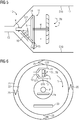
- Fig. 6 shows a computer tomograph 20 in a sixth embodiment.
- the computer tomograph 20 has a stationary carrier ring 21 and a rotating carrier ring 22.
- the stationary support ring 21 and the rotating support ring 22 comprise, for example, metal and / or plastic and are typically rotationally symmetrical.
- the computer tomograph shows the rotating support ring 22 without the computer tomograph housing.
- the rotating support ring 22 has an X-ray emitter 10 and an X-ray detector 23.
- a patient P is positioned on a patient bed 24 between the X-ray emitter 10 and the X-ray detector 23.
- an object for example a suitcase, can be transilluminated with the X-rays.
- the computer tomograph 20 is designed in such a way that the convection of the gaseous cooling medium L forced by the compressor V of the X-ray tube 10 is intensified by the rotation of the rotating support ring 22.
- the air inlet opening 12 is such aligned so that the gaseous cooling medium L is guided and / or pressed into the X-ray tube housing G10 during the rotation of the rotating support ring 22.
- the stationary carrier ring 21 has an optional profiling 25 in order to additionally reinforce the forced convection.
- the rotating carrier ring can have a profile.
- the profiling 25 can in particular be designed in such a way that the gaseous cooling medium L is guided and / or pressed into the X-ray emitter housing G10.
- the profiling 25 can in particular have further turbine blades and / or be wave-shaped and / or spiral-shaped.
- the compressor Due to the multiple turbine blades T1 ... TN of the compressor V, the compressor is an active compressor. If the multiple turbine blades T1 ... TN are replaced by static turbine blades, the passive compressor can be designed for cooling the X-ray tube 10, in particular if the convection of the gaseous cooling medium L forced by the compressor V of the X-ray tube 10 is caused by the rotation of the rotating support ring 22 is reinforced.
Abstract
Die Erfindung betrifft einen Röntgenstrahler und einen Computertomographen.Der erfindungsgemäße Röntgenstrahler (10) weist- eine Röntgenröhre (11) und- ein Röntgenstrahlergehäuse (G10) auf,- wobei die Röntgenröhre ein evakuiertes Röntgenröhrengehäuse (G11), eine Kathode (K) zur Emission von Elektronen (E) und eine Anode (A) zur Generierung von Röntgenstrahlen in Abhängigkeit der Elektronen aufweist,- wobei das Röntgenstrahlergehäuse die Röntgenröhre und außerhalb der Röntgenröhre ein gasförmiges Kühlmedium (L) aufweist, gekennzeichnet durch- einen Verdichter (V) für eine erzwungene Konvektion des gasförmigen Kühlmediums zur Kühlung der Röntgenröhre, wobei ein Druckverhältnis zwischen Ansaugseite und Druckseite des Verdichters größer ist als 1,3.The invention relates to an X-ray emitter and a computer tomograph. The X-ray emitter (10) according to the invention has an X-ray tube (11) and an X-ray tube housing (G10), the X-ray tube being an evacuated X-ray tube housing (G11), a cathode (K) for emitting Has electrons (E) and an anode (A) for generating X-rays depending on the electrons, - the X-ray tube housing having the X-ray tube and outside the X-ray tube a gaseous cooling medium (L), characterized by - a compressor (V) for forced convection of the gaseous cooling medium for cooling the X-ray tube, a pressure ratio between the suction side and pressure side of the compressor being greater than 1.3.
Description
Die Erfindung betrifft einen Röntgenstrahler und einen Computertomographen.The invention relates to an X-ray source and a computer tomograph.
Üblicherweise weist ein Röntgenstrahler eine Röntgenröhre zur Generierung von Röntgenstrahlen auf, wofür insbesondere die Röntgenröhre gekühlt wird. Typischerweise wird für die Kühlung der Röntgenröhre ein flüssiges Kühlmedium verwendet, insbesondere Öl. Mit dem flüssigen Kühlmedium kann die Röntgenröhre aktiv oder passiv gekühlt werden. Bei der passiven Kühlung mit dem flüssigen Kühlmedium wird die Röntgenröhre insbesondere mittels Konvektion gekühlt. Bei der aktiven Kühlung mit dem flüssigen Kühlmedium wird typischerweise der Röntgenröhre ein abgekühltes flüssiges Kühlmedium zugeführt und ein erwärmtes flüssiges Kühlmedium entnommen.An x-ray emitter usually has an x-ray tube for generating x-rays, for which purpose the x-ray tube in particular is cooled. A liquid cooling medium, in particular oil, is typically used to cool the X-ray tube. The X-ray tube can be actively or passively cooled with the liquid cooling medium. In the case of passive cooling with the liquid cooling medium, the X-ray tube is cooled in particular by means of convection. In the case of active cooling with the liquid cooling medium, a cooled liquid cooling medium is typically fed to the X-ray tube and a heated liquid cooling medium is removed.
Für die aktive Kühlung mit dem flüssigen Kühlmedium benötigt der Röntgenstrahler typischerweise einen Wärmetauscher zum Transferieren einer Wärmeenergie. Zusätzlich zum Wärmetauscher weist ein derartiger Röntgenstrahler typischerweise Schläuche und entsprechende Kupplungen auf, wodurch eine Komplexität und/oder ein Gewicht des Röntgenstrahlers üblicherweise signifikant erhöht ist.For active cooling with the liquid cooling medium, the X-ray emitter typically requires a heat exchanger to transfer thermal energy. In addition to the heat exchanger, such an x-ray emitter typically has hoses and corresponding couplings, as a result of which the complexity and / or weight of the x-ray emitter is usually significantly increased.
Aus der
Die
In der
Aus der
Bei den vorstehend beschriebenen Röntgenstrahlern mit einem gasförmigen Kühlmedium (z.B. Luft) erfolgt die Zirkulation des gasförmigen Kühlmediums typischerweise durch einen Ventilator, der außerhalb des evakuierten Röntgenröhrengehäuses im Röntgenstrahlergehäuse angeordnet ist. Mit einem derartigen Ventilator ist nur eine geringe Wärmeabfuhr, insbesondere Kühlung, realisierbar, so dass - trotz der konstruktiv aufwändigen Lösung - für Röntgenstrahler nach wie vor die beschriebene Öl-Kühlung regelmäßig eingesetzt wird.In the case of the X-ray emitters with a gaseous cooling medium (e.g. air) described above, the gaseous cooling medium is typically circulated by a fan which is arranged outside the evacuated X-ray tube housing in the X-ray emitter housing. With such a fan, only a small amount of heat dissipation, in particular cooling, can be achieved, so that - despite the structurally complex solution - the described oil cooling is still regularly used for X-ray tubes.
In der
Der Erfindung liegt die Aufgabe zu Grunde, einen Röntgenstrahler und einen Computertomographen anzugeben, bei welchen die Kühlung verbessert wird.The invention is based on the object of specifying an X-ray source and a computer tomograph in which the cooling is improved.
Die Aufgabe wird durch die Merkmale der unabhängigen Ansprüche gelöst. Vorteilhafte Ausgestaltungen sind in den Unteransprüchen beschrieben.The object is achieved by the features of the independent claims. Advantageous refinements are described in the subclaims.
Der erfindungsgemäße Röntgenstrahler weist
- eine Röntgenröhre und
- ein Röntgenstrahlergehäuse auf,
- wobei die Röntgenröhre ein evakuiertes Röntgenröhrengehäuse, eine Kathode zur Emission von Elektronen und eine Anode zur Generierung von Röntgenstrahlen in Abhängigkeit der Elektronen aufweist,
- wobei das Röntgenstrahlergehäuse die Röntgenröhre und außerhalb der Röntgenröhre ein gasförmiges Kühlmedium aufweist, gekennzeichnet durch
- einen Verdichter für eine erzwungene Konvektion des gasförmigen Kühlmediums zur Kühlung der Röntgenröhre, wobei ein Druckverhältnis zwischen Ansaugseite und Druckseite des Verdichters größer ist als 1,3.
- an x-ray tube and
- an x-ray tube housing,
- wherein the X-ray tube has an evacuated X-ray tube housing, a cathode for emitting electrons and an anode for generating X-rays as a function of the electrons,
- wherein the x-ray emitter housing has the x-ray tube and a gaseous cooling medium outside the x-ray tube, characterized by
- a compressor for forced convection of the gaseous cooling medium for cooling the X-ray tube, a pressure ratio between the suction side and the pressure side of the compressor being greater than 1.3.
Ein Vorteil des Röntgenstrahler ist, dass die Kühlung des Röntgenstrahlers, insbesondere der Röntgenröhre, mit dem gasförmigen Kühlmedium eine Gewichtseinsparung von mehr als 10%, vorzugsweise mehr als 30%, im Vergleich zu einem mit einem flüssigen Kühlmedium gekühlten Röntgenstrahler ermöglicht. Typischerweise ist der Röntgenstrahler mit dem Verdichter leichter als ein herkömmlicher Röntgenstrahler. Ein weiterer Vorteil ist, dass eine Streuung der Röntgenstrahlen durch das gasförmige Kühlmedium wesentlicher geringer ist als eine Streuung der Röntgenstrahlen durch das flüssige Kühlmedium, wodurch vorzugsweise eine Bildqualität eines mittels der Röntgenstrahlen erfassten Bildes erhöht wird. Vorteilhafterweise fällt ein Entsorgungsproblem des flüssigen Kühlmediums dadurch weg, dass der Verdichter das gasförmige Kühlmedium zur Kühlung bereitstellt.An advantage of the X-ray tube is that the cooling of the X-ray tube, in particular the tube, with the gaseous cooling medium enables a weight saving of more than 10%, preferably more than 30%, compared to an X-ray tube cooled with a liquid cooling medium. Typically, the x-ray tube with the compressor is lighter than a conventional x-ray tube. Another advantage is that the X-rays are scattered by the gaseous cooling medium is substantially less than a scattering of the X-rays by the liquid cooling medium, whereby an image quality of an image captured by means of the X-rays is preferably increased. A disposal problem of the liquid cooling medium is advantageously eliminated in that the compressor provides the gaseous cooling medium for cooling.
Der Röntgenstrahler kann in einem klinischen und/oder medizinischen Umfeld eingesetzt werden. Grundsätzlich ist es denkbar, dass der Röntgenstrahler für eine Materialprüfung und/oder für eine nicht-medizinische Durchleuchtung von Objekten außerhalb des klinischen und/oder medizinischen Umfelds, insbesondere in einem Sicherheitsumfeld eingesetzt wird.The x-ray emitter can be used in a clinical and / or medical environment. In principle, it is conceivable that the x-ray emitter is used for material testing and / or for non-medical fluoroscopy of objects outside the clinical and / or medical environment, in particular in a security environment.
Das Röntgenstrahlergehäuse weist üblicherweise Metall und/oder Glas auf und/oder ist im Wesentlichen zylinderförmig und/oder trichterförmig. Die Röntgenröhre, insbesondere das evakuierte Röntgenröhrengehäuse, ist typischerweise innerhalb des Röntgenstrahlergehäuses angeordnet. Typischerweise ist die Röntgenröhre nicht als eine Stehanoden-Röntgenröhre ausgebildet. Üblicherweise rotiert also wenigstens die Anode relativ zum Röntgenstrahlergehäuse.The x-ray emitter housing usually comprises metal and / or glass and / or is essentially cylindrical and / or funnel-shaped. The x-ray tube, in particular the evacuated x-ray tube housing, is typically arranged within the x-ray tube housing. The x-ray tube is typically not designed as a standing anode x-ray tube. Usually, at least the anode rotates relative to the x-ray tube housing.
Die Kathode kann einen Emitter zur Emission der Elektronen und/oder einen Fokuskopf aufweisen. Der Emitter kann ein Wendelemitter, ein Flachemitter, ein Feldeffekt-Emitter, ein direkt oder indirekt beheizbarer Emitter oder eine Kombination dergleichen sein.The cathode can have an emitter for emitting the electrons and / or a focus head. The emitter can be a helical emitter, a flat emitter, a field effect emitter, a directly or indirectly heatable emitter or a combination of the like.
Die Kathode und/oder die Anode sind typischerweise innerhalb des evakuierten Röntgenröhrengehäuses der Röntgenröhre angeordnet und/oder aufeinander ausgerichtet. Die Elektronen werden üblicherweise mit einer Beschleunigungsspannung von der Kathode auf die Anode zu beschleunigt. Die Beschleunigungsspannung ist typischer größer 10 kV und kleiner 200 kV, insbesondere zwischen 60 kV und 150 kV. Die Röntgenstrahlen werden üblicherweise bei einer Interaktion der beschleunigten Elektronen mit der Anode generiert. Die Anode weist typischerweise Wolfram, Gold, Rhenium, Rhodium, Molybdän und/oder eine Legierung der vorherigen Elemente auf. Grundsätzlich ist es denkbar, dass die Röntgenröhre den Fokuskopf und/oder eine elektromagnetische Ablenkeinheit zu einem Ablenken, insbesondere zu einem Fokussieren, der emittierten Elektronen aufweist. Üblicherweise wird weniger als 5% einer kinetischen Energie der beschleunigten Elektronen in Röntgenstrahlen umgewandelt, wobei die restliche Energie in Form von Hitze insbesondere an der Anode entsteht. Typischerweise muss die Anode am stärksten gekühlt werden.The cathode and / or the anode are typically arranged within the evacuated X-ray tube housing of the X-ray tube and / or aligned with one another. The electrons are usually accelerated from the cathode to the anode with an acceleration voltage. The acceleration voltage is typically greater than 10 kV and less than 200 kV, in particular between 60 kV and 150 kV. The X-rays are usually generated when the accelerated electrons interact with the anode. The anode typically comprises tungsten, gold, rhenium, rhodium, molybdenum and / or an alloy of the previous elements. In principle, it is conceivable that the x-ray tube has the focus head and / or an electromagnetic deflection unit for deflecting, in particular for focusing, the emitted electrons. Usually less than 5% of the kinetic energy of the accelerated electrons is converted into X-rays, with the remaining energy being generated in the form of heat, particularly at the anode. Typically, the anode needs to be cooled the most.
Das Röntgenröhrengehäuse ist typischerweise luftdicht verschlossen. Während die Kathode und die Anode in dem evakuierten Röntgenröhrengehäuse angeordnet sind, ist typischerweise außerhalb der Röntgenröhre und innerhalb des Röntgenstrahlergehäuses das gasförmige Kühlmedium. Das gasförmige Kühlmedium weist üblicherweise Luft, insbesondere getrocknete Luft, Stickstoff, Sauerstoff, Neon, Kohlendioxid, Schwefelhexafluorid und/oder eine Mischung der vorherigen Elemente auf. Grundsätzlich ist es denkbar, dass das gasförmige Kühlmedium ausschließlich aus Luft besteht. Die Röntgenröhre, insbesondere das Röntgenröhrengehäuse und/oder die Anode und/oder die Kathode, werden vorzugsweise mittels des gasförmigen Kühlmediums gekühlt. Die Kühlung erfolgt insbesondere ohne ein flüssiges Kühlmedium. Mittels des Verdichters kann die Röntgenröhre vorzugsweise derart gekühlt werden, dass ein Dauerbetrieb des Röntgenstrahlers, beispielsweise im medizinischen Umfeld ermöglicht wird. Der Dauerbetrieb des Röntgenstrahlers umfasst beispielsweise mehrere konsekutive bildgebende Untersuchungen mit Röntgenstrahlen eines Patienten ohne Kühlpause und/oder konsekutive bildgebende Untersuchungen mit Röntgenstrahlen mehrerer Patienten ohne Kühlpause. Ein durch den Verdichter erwirkter Wärmeübergangskoeffizient innerhalb des Röntgenstrahlers beträgt insbesondere mindestens 300 W/(K∗m^2), vorzugsweise mindestens 1000 W/(K∗m^2), besonderes vorteilhafterweise mindestens 1500 W/(K∗m^2).The x-ray tube housing is typically hermetically sealed. While the cathode and the anode are arranged in the evacuated X-ray tube housing, the gaseous cooling medium is typically outside the X-ray tube and inside the X-ray tube housing. The gaseous cooling medium usually comprises air, in particular dried air, nitrogen, oxygen, neon, carbon dioxide, sulfur hexafluoride and / or a mixture of the previous elements. In principle, it is conceivable that the gaseous cooling medium consists exclusively of air. The X-ray tube, in particular the X-ray tube housing and / or the anode and / or the cathode, are preferably cooled by means of the gaseous cooling medium. The cooling takes place in particular without a liquid cooling medium. The x-ray tube can preferably be cooled by means of the compressor in such a way that continuous operation of the x-ray source, for example in a medical environment, is made possible. The continuous operation of the X-ray emitter includes, for example, several consecutive imaging examinations with X-rays of a patient without a cooling break and / or consecutive imaging examinations with X-rays from several patients without a cooling break. A heat transfer coefficient achieved by the compressor within the X-ray emitter is in particular at least 300 W / (K ∗ m ^ 2), preferably at least 1000 W / (K ∗ m ^ 2), in particular advantageously at least 1500 W / (K ∗ m ^ 2).
Es ist denkbar, dass das Röntgenstrahlergehäuse insbesondere eine Zuluftöffnung und eine Abluftöffnung aufweist. Die Zuluftöffnung kann insbesondere auf der Ansaugseite des Verdichters sein. Die Abluftöffnung kann insbesondere auf der Druckseite des Verdichters sein. Die Kühlung erfolgt insbesondere durch die erzwungene Konvektion, wobei Wärme von der Röntgenröhre weg mittels des gasförmigen Kühlmediums übertragen wird. Das gasförmige Kühlmedium ist insbesondere an der Abluftöffnung wärmer als an der Zuluftöffnung. Das gasförmige Kühlmedium strömt insbesondere von der Zuluftöffnung zur Abluftöffnung.It is conceivable that the x-ray emitter housing has, in particular, an air inlet opening and an air outlet opening. The air inlet opening can in particular be on the suction side of the compressor. The exhaust air opening can in particular be on the pressure side of the compressor. The cooling takes place in particular by means of forced convection, with heat being transferred away from the X-ray tube by means of the gaseous cooling medium. The gaseous cooling medium is warmer in particular at the exhaust air opening than at the supply air opening. The gaseous cooling medium flows in particular from the inlet air opening to the exhaust air opening.
Typischerweise korreliert der Wärmeübergangskoeffizient mit einem Druckverhältnis des Verdichters. Vorzugsweise ist auf der Druckseite des Verdichters der Druck um mindestens 0,5 Bar, vorzugsweise um 1 Bar, besonders vorteilhafterweise um 2 Bar oder 4 Bar höher als der Druck auf der Ansaugseite. Wenn auf der Ansaugseite des Verdichters ein atmosphärischer Druck von ca. 1 Bar ist und auf der Druckseite der Druck ca. 1,5 Bar ist, dann beträgt das Druckverhältnis 1,5. In diesem Fall ist also das Druckverhältnis des Verdichters größer 1,3. In einem weiteren Ausführungsbeispiel ist das Druckverhältnis größer als 2, vorzugsweise größer als 4, besonders vorteilhafterweise größer als 8. Das Druckverhältnis kann insbesondere an der Außenseite des Röntgenröhrengehäuses auf Höhe der Anode am größten sein.The heat transfer coefficient typically correlates with a pressure ratio of the compressor. The pressure on the pressure side of the compressor is preferably at least 0.5 bar, preferably 1 bar, particularly advantageously 2 bar or 4 bar higher than the pressure on the suction side. If there is an atmospheric pressure of approx. 1 bar on the suction side of the compressor and the pressure is approx. 1.5 bar on the pressure side, then the pressure ratio is 1.5. In this case, the pressure ratio of the compressor is greater than 1.3. In a further exemplary embodiment, the pressure ratio is greater than 2, preferably greater than 4, particularly advantageously greater than 8. The pressure ratio can in particular be greatest on the outside of the x-ray tube housing at the level of the anode.
Der Verdichter kann aktiv oder passiv sein. Der passive Verdichter weist beispielsweise eine passive Vorrichtung auf, welche insbesondere aufgrund der äußeren Beschaffenheit und/oder Form die Konvektion erzwingt. Der aktive Verdichter weist beispielsweise eine aktive Vorrichtung mit Verdichterelementen auf, welche Verdichterelemente insbesondere durch eine direkte oder indirekte Zufuhr von elektrischer oder mechanischer Leistung die Konvektion erzwingen. Der aktive Verdichter kann beispielsweise zusätzlich die passive Vorrichtung des passiven Verdichters aufweisen.The compressor can be active or passive. The passive compressor has, for example, a passive device which, in particular due to its external nature and / or shape, forces convection. The active compressor has, for example, an active device with compressor elements, which compressor elements force convection in particular through a direct or indirect supply of electrical or mechanical power. Of the Active compressor can, for example, additionally have the passive device of the passive compressor.
Eine Ausführungsform sieht vor, dass das Röntgenstrahlergehäuse und das Röntgenröhrengehäuse als turbinenförmiger Verdichter zum Erzwingen der Konvektion ausgebildet sind. Diese Ausführungsform kann insbesondere vorteilhaft sein, da die Konvektion vorzugsweise passiv erzwungen werden kann. Der turbinenförmige Verdichter ist in dieser Ausführungsform ein passiver Verdichter. Zum Erzwingen der Konvektion kann der turbinenförmige Verdichter insbesondere einen sich verjüngenden Querschnitt aufweisen und/oder trichterförmig sein. Eine Innenseite des Röntgenstrahlergehäuse und/oder eine Außenseite des Röntgenröhrengehäuse können eine Profilierung zum Erzwingen der Konvektion aufweisen. Insbesondere für einen Röntgenstrahler mit einer vergleichsweise geringen Leistung und entsprechender Wärmeentwicklung kann eine passiv erzwungene Konvektion ausreichend sein. Ein weiterer Vorteil dieser Ausführungsform kann sein, dass ein Verschleiß des Röntgenstrahlers im Vergleich zu einem herkömmlichen Röntgenstrahler mit einem Ventilator verringert ist. Ein Wärmeübergangskoeffizient dieser Ausführungsform ist insbesondere größer 300 W/(K∗m^2), vorzugsweise größer 1500 W/(K∗m^2).One embodiment provides that the x-ray emitter housing and the x-ray tube housing are designed as turbine-shaped compressors for forcing convection. This embodiment can be particularly advantageous since convection can preferably be forced passively. The turbine-shaped compressor is a passive compressor in this embodiment. To force convection, the turbine-shaped compressor can in particular have a tapering cross section and / or be funnel-shaped. An inside of the x-ray emitter housing and / or an outside of the x-ray tube housing can have a profile to force convection. Passively forced convection can be sufficient, in particular for an X-ray source with a comparatively low output and corresponding heat generation. A further advantage of this embodiment can be that wear and tear on the x-ray emitter is reduced compared to a conventional x-ray emitter with a fan. A heat transfer coefficient of this embodiment is in particular greater than 300 W / (K ∗ m ^ 2), preferably greater than 1500 W / (K ∗ m ^ 2).
Eine Ausführungsform sieht vor, dass die Anode sich mit einer relativ zum Röntgenstrahlergehäuse rotierenden Welle dreht, wobei der Verdichter mehrere Turbinenschaufeln zum Erzwingen der Konvektion aufweist und wobei die mehreren Turbinenschaufeln derart auf der rotierenden Welle gelagert sind, dass eine Drehgeschwindigkeit der Anode und eine Drehgeschwindigkeit der mehreren Turbinenschaufeln voneinander abhängen. Die Drehgeschwindigkeit der Anode korreliert insbesondere mit der Drehgeschwindigkeit der mehreren Turbinenschaufeln. Der Verdichter mit den mehreren sich drehenden Turbinenschaufeln ist insbesondere ein aktiver Verdichter. Diese Ausführungsform ist insbesondere vorteilhaft, wenn die mehreren Turbinenschaufeln und die Anode mittels der rotierenden Welle vorzugsweise fest verbunden, insbesondere mechanisch gekoppelt sind. Die mehreren Turbinenschaufeln drehen sich insbesondere mit der Anode und/oder mit der rotierenden Welle mit, typischerweise mit einer korrelierten oder mit derselben Drehgeschwindigkeit. Grundsätzlich ist es denkbar, dass die mehreren Turbinenschaufeln und die Anode über ein Getriebe mit einem Übersetzungsverhältnis insbesondere ungleich 1 gekoppelt sind, wodurch die Drehgeschwindigkeit der mehreren Turbinenschaufeln und die Drehgeschwindigkeit der Anode sich unterscheiden können, aber zumindest korrelieren. Die Drehgeschwindigkeit der mehreren Turbinenschaufeln und die Drehgeschwindigkeit der Anode können sich insbesondere entsprechen. Insbesondere wenn die Anode und die mehreren Turbinenschaufeln auf der rotierenden Welle, insbesondere ohne Getriebe, gelagert sind, kann die Drehgeschwindigkeit der Anode der Drehgeschwindigkeit der mehreren Turbinenschaufeln entsprechen. Diese Ausführungsform ist insbesondere vorteilhaft, weil ein Motor der Röntgenröhre für das Drehen der mehreren Turbinenschaufeln und der Anode verwendet werden kann. Die mehreren Turbinenschaufeln und die Anode werden insbesondere vom Motor der Röntgenröhre gleichzeitig angetrieben. Die mehreren Turbinenschaufeln können auf mehreren Turbinenschaufelebenen verteilt angeordnet sein. Grundsätzlich ist es denkbar, dass der Verdichter zusätzlich zu den sich drehenden Turbinenschaufeln statische Turbinenschaufeln aufweist, um die Konvektion zu erzwingen und/oder um die erzwungene Konvektion zu verstärken. Diese Ausführungsform kann insbesondere für einen Röntgenstrahler mit einer vergleichsweisen hohen Leistung und entsprechender Wärmeentwicklung vorteilhaft sein. Mittels der mehreren Turbinenschaufeln wird die Konvektion insbesondere aktiv erzwungen. Ein Wärmeübergangskoeffizient dieser Ausführungsform ist insbesondere größer 300 W/(K∗m^2), vorzugsweise größer 1500 W/(K∗m^2).One embodiment provides that the anode rotates with a shaft rotating relative to the x-ray emitter housing, the compressor having several turbine blades for forcing the convection and the several turbine blades being mounted on the rotating shaft in such a way that a rotational speed of the anode and a rotational speed of the several turbine blades depend on each other. The speed of rotation of the anode correlates in particular with the speed of rotation of the plurality of turbine blades. The compressor with the plurality of rotating turbine blades is in particular an active compressor. This embodiment is particularly advantageous when the plurality of turbine blades and the anode by means of the rotating shaft are preferably firmly connected, in particular mechanically coupled. The plurality of turbine blades rotate in particular with the anode and / or with the rotating shaft, typically with a correlated or with the same rotational speed. In principle, it is conceivable that the multiple turbine blades and the anode are coupled via a transmission with a transmission ratio, in particular not equal to 1, whereby the rotational speed of the multiple turbine blades and the rotational speed of the anode can differ, but at least correlate. The speed of rotation of the plurality of turbine blades and the speed of rotation of the anode can in particular correspond to one another. In particular if the anode and the plurality of turbine blades are mounted on the rotating shaft, in particular without a gearbox, the rotational speed of the anode can correspond to the rotational speed of the plurality of turbine blades. This embodiment is particularly advantageous because one motor of the x-ray tube can be used to rotate the plurality of turbine blades and the anode. In particular, the multiple turbine blades and the anode are driven simultaneously by the motor of the x-ray tube. The plurality of turbine blades can be arranged in a distributed manner on a plurality of turbine blade planes. In principle, it is conceivable that the compressor, in addition to the rotating turbine blades, has static turbine blades in order to force the convection and / or to intensify the forced convection. This embodiment can be advantageous in particular for an X-ray source with a comparatively high output and corresponding heat generation. The convection is particularly actively forced by means of the multiple turbine blades. A heat transfer coefficient of this embodiment is in particular greater than 300 W / (K ∗ m ^ 2), preferably greater than 1500 W / (K ∗ m ^ 2).
In einer bevorzugten Ausführungsform sind der turbinenförmige Verdichter und die mehreren Turbinenschaufeln der beiden vorher beschriebenen Ausführungsformen in dem Röntgenstrahler enthalten, was insbesondere für besonders leistungsfähige Röntgenstrahler mit entsprechender Wärmeentwicklung vorteilhaft sein kann. In diesem bevorzugten Ausführungsbeispiel ist also ein aktiver Verdichter enthalten. Der Röntgenstrahler ist in diesem Ausführungsbeispiel derart ausgebildet, dass das Röntgenstrahlergehäuse und das Röntgenröhrengehäuse als turbinenförmiger Verdichter zum Erzwingen der Konvektion ausgebildet sind und dass die Anode sich mit der relativ zum Röntgenstrahlergehäuse rotierenden Welle dreht, wobei der Verdichter die mehreren Turbinenschaufeln zum Erzwingen der Konvektion aufweist und wobei die mehreren Turbinenschaufeln derart auf der rotierenden Welle gelagert sind, dass die Drehgeschwindigkeit der Anode der Drehgeschwindigkeit des Verdichters entspricht. Ein Wärmeübergangskoeffizient dieser Ausführungsform ist insbesondere größer 300 W/(K∗m^2), vorzugsweise größer 1500 W/(K∗m^2).In a preferred embodiment, the turbine-shaped compressor and the plurality of turbine blades of the two previously described embodiments are in the X-ray tube included, which can be particularly advantageous for particularly powerful X-ray tubes with a corresponding heat generation. In this preferred embodiment, an active compressor is included. In this exemplary embodiment, the x-ray emitter is designed in such a way that the x-ray tube housing and the x-ray tube housing are designed as a turbine-shaped compressor for forcing convection and that the anode rotates with the shaft rotating relative to the x-ray tube housing, the compressor having several turbine blades for forcing convection and wherein the plurality of turbine blades are supported on the rotating shaft such that the rotational speed of the anode corresponds to the rotational speed of the compressor. A heat transfer coefficient of this embodiment is in particular greater than 300 W / (K ∗ m ^ 2), preferably greater than 1500 W / (K ∗ m ^ 2).
Eine Ausführungsform sieht vor, dass die Röntgenröhre als eine Drehkolben-Röntgenröhre ausgebildet ist, wobei eine Drehgeschwindigkeit des Röntgenröhrengehäuses der Drehgeschwindigkeit der Anode entspricht. Vorteilhafterweise ist in der Drehkolben-Röntgenröhre lediglich ein Motor für das Rotieren der Anode und der Turbinenschaufeln und insbesondere für das Rotieren des Röntgenröhrengehäuses vorhanden. Diese Ausführungsform ist insbesondere vorteilhaft, weil bei der Drehkolben-Röntgenröhre das evakuierte Röntgenröhrengehäuse sich gemeinsam mit der Anode relativ zum Röntgenstrahlergehäuse dreht. Ein Drehwiderstand durch das gasförmige Kühlmedium ist im Vergleich zu einem Drehwiderstand durch ein herkömmliches flüssiges Kühlmedium vorzugsweise geringer. Die Drehkolben-Röntgenröhre kann sich vorzugsweise leichter drehen. Vorteilhafterweise kann eine Motorleistung der Drehkolben-Röntgenröhre daher geringer und/oder der zugehörige Motor günstiger sein. Ein weiterer Vorteil ist typischerweise, dass eine Peek-Hülle der Drehkolben-Röntgenröhre entfallen kann. Die Peek-Hülle weist üblicherweise Polyetheretherketon auf, welches insbesondere ein hochtemperetaturbeständiger thermoplastischer Kunststoff ist, und/oder ist üblicherweise in einem herkömmlichen Röntgenstrahler als zusätzliche Hülle des Röntgenröhrengehäuses drehbar gelagert, um eine Antriebsleistung der herkömmlichen Röntgenröhre zu verringern.One embodiment provides that the X-ray tube is designed as a rotary piston X-ray tube, a rotational speed of the X-ray tube housing corresponding to the rotational speed of the anode. Advantageously, only one motor for rotating the anode and the turbine blades and in particular for rotating the X-ray tube housing is present in the rotary piston x-ray tube. This embodiment is particularly advantageous because in the rotary piston x-ray tube the evacuated x-ray tube housing rotates together with the anode relative to the x-ray tube housing. A resistance to rotation due to the gaseous cooling medium is preferably lower compared to a resistance to rotation due to a conventional liquid cooling medium. The rotary piston X-ray tube can preferably rotate more easily. Advantageously, a motor output of the rotary piston x-ray tube can therefore be lower and / or the associated motor can be cheaper. Another advantage is typically that a peek cover for the rotary piston X-ray tube can be omitted. The PEEK shell usually has polyetheretherketone, which is in particular a high temperature resistant thermoplastic plastic is, and / or is usually rotatably mounted in a conventional X-ray tube as an additional shell of the X-ray tube housing in order to reduce a drive power of the conventional X-ray tube.
Eine zur Ausbildung als Drehkolben-Röntgenröhre alternative Ausführungsform sieht vor, dass die Röntgenröhre als eine Drehanoden-Röntgenröhre ausgebildet ist, wobei das Röntgenröhrengehäuse relativ zum Röntgenstrahlergehäuse ortsfest ist. In diesem Fall dreht sich das evakuierte Röntgenröhrengehäuse nicht relativ zum Röntgenstrahlergehäuse. Vorteilhafterweise ist in der Drehanoden-Röntgenröhre lediglich ein Motor für das Rotieren der Anode und der Turbinenschaufeln vorhanden.An embodiment alternative to the design as a rotary piston x-ray tube provides that the x-ray tube is designed as a rotating anode x-ray tube, the x-ray tube housing being stationary relative to the x-ray emitter housing. In this case, the evacuated x-ray tube housing does not rotate relative to the x-ray tube housing. Advantageously, only one motor for rotating the anode and the turbine blades is present in the rotating anode x-ray tube.
Eine Ausführungsform sieht vor, dass das Röntgenröhrengehäuse ein Röntgenstrahlenaustrittfenster aufweist, wobei der Röntgenstrahler zusätzlich zum Verdichter eine Kühlplatte mit mehreren Löchern für eine Prallkühlung aufweist und wobei die Kühlplatte mit den mehreren Löchern relativ zum Röntgenstrahlenaustrittfenster derart ausgerichtet ist, dass ein durch die Kühlplatte in Abhängigkeit der erzwungenen Konvektion gerichteter gasförmiger Strom auf das Röntgenstrahlenaustrittfenster zur Prallkühlung auftrifft. Das Röntgenstrahlenaustrittfenster wird typischerweise von den Röntgenstrahlen zu einem Verlassen des Röntgenröhrengehäuses durchleuchtet, wobei das Röntgenstrahlenaustrittfenster sich typischerweise erhitzt. Diese Ausführungsform ermöglicht vorzugsweise eine ausreichende Kühlung des Röntgenstrahlenaustrittfensters mit dem gasförmigen Kühlmedium, insbesondere für konsekutive bildgebende Untersuchungen mit Röntgenstrahlung. Ein Wärmeübergangskoeffizient dieser Ausführungsform ist insbesondere größer 300 W/(K∗m^2), vorzugsweise größer 1500 W/(K∗m^2).One embodiment provides that the X-ray tube housing has an X-ray exit window, the X-ray tube having a cooling plate with several holes for impingement cooling in addition to the compressor and the cooling plate with the several holes being oriented relative to the X-ray exit window in such a way that a through the cooling plate depending on the Forced convection directed gaseous flow impinges on the X-ray exit window for impingement cooling. The x-ray exit window is typically transilluminated by the x-rays to exit the x-ray tube housing, the x-ray exit window typically heating up. This embodiment preferably enables sufficient cooling of the X-ray exit window with the gaseous cooling medium, in particular for consecutive imaging examinations with X-rays. A heat transfer coefficient of this embodiment is in particular greater than 300 W / (K ∗ m ^ 2), preferably greater than 1500 W / (K ∗ m ^ 2).
Eine Ausführungsform sieht vor, dass der Röntgenstrahler zusätzlich zum Verdichter eine Kühlplatte mit mehreren Nadeln für eine Pin-Fin-Kühlung aufweist und dass die mehreren Nadeln der Kühlplatte derart mit dem Röntgenröhrengehäuse befestigt sind, dass ein zwischen den Nadeln in Abhängigkeit der erzwungenen Konvektion gerichteter gasförmiger Strom auf das Röntgenröhrengehäuse zur Kühlung auftrifft. Die Kühlplatte kann insbesondere auf der Außenseite des Röntgenröhrengehäuses auf einer Höhe zwischen der Anode und der Kathode angeordnet sein. Ein Wärmeübergangskoeffizient dieser Ausführungsform ist insbesondere größer 300 W/(K∗m^2), vorzugsweise größer 1500 W/(K∗m^2).One embodiment provides that, in addition to the compressor, the x-ray emitter has a cooling plate with several needles for pin-fin cooling and that the several Needles of the cooling plate are fastened to the X-ray tube housing in such a way that a gaseous flow directed between the needles as a function of the forced convection impinges on the X-ray tube housing for cooling. The cooling plate can in particular be arranged on the outside of the X-ray tube housing at a level between the anode and the cathode. A heat transfer coefficient of this embodiment is in particular greater than 300 W / (K ∗ m ^ 2), preferably greater than 1500 W / (K ∗ m ^ 2).
Der erfindungsgemäße Computertomograph weist einen stationären Trägerring und einen rotierenden Trägerring auf, wobei der rotierende Trägerring den Röntgenstrahler und einen Röntgendetektor aufweist. Typischerweise werden mit den Röntgenstrahlen erzeugte Schwächungsprofile an dem Röntgendetektor erfasst, woraus ein röntgenstrahlenbasiertes Bild rekonstruiert werden kann. Das röntgenstrahlenbasierte Bild kann beispielsweise auf einer Anzeigeeinheit bereitgestellt und/oder in einer Speichereinheit abgespeichert werden. Vorteilhafterweise kann eine Motorleistung eines Motors des Computertomographen zum Bereitstellen einer Eigenrotation des rotierenden Teils verringert werden, weil der Röntgenstrahler anstatt mit dem herkömmlichen flüssigen Kühlmedium mit dem gasförmigen Kühlmedium gekühlt wird und typischerweise daher leichter ist. Vorzugsweise kann der rotierende Trägerring kleiner und/oder leichter und/oder weniger stabil ausgeführt werden, wenn der Röntgenstrahler leichter ist.The computer tomograph according to the invention has a stationary carrier ring and a rotating carrier ring, the rotating carrier ring having the X-ray emitter and an X-ray detector. Attenuation profiles generated with the X-rays are typically detected on the X-ray detector, from which an X-ray-based image can be reconstructed. The X-ray-based image can, for example, be provided on a display unit and / or stored in a memory unit. Advantageously, a motor output of a motor of the computer tomograph for providing a self-rotation of the rotating part can be reduced because the x-ray emitter is cooled with the gaseous cooling medium instead of the conventional liquid cooling medium and is therefore typically lighter. The rotating support ring can preferably be designed to be smaller and / or lighter and / or less stable if the x-ray emitter is lighter.
Eine Ausführungsform sieht vor, dass der Computertomograph derart ausgebildet ist, dass die durch den Verdichter des Röntgenstrahlers erzwungene Konvektion des gasförmigen Kühlmediums durch eine Eigenrotation des rotierenden Trägerrings verstärkt wird. Die Eigenrotation des rotierenden Trägerrings kann vorzugsweise einen Luftstrom auf der Ansaugseite des Verdichters derart bereitstellen, dass der Druck auf der Druckseite des Verdichters erhöht ist und/oder damit die Kühlung durch den Verdichter verstärkt wird. Die Eigenrotation des rotierenden Trägerring beschreibt insbesondere ein Rotieren des Trägerrings mit dem Röntgenstrahler um 360°. Eine Frequenz der Eigenrotation beträgt insbesondere mehr als 0,1 Hz, vorzugsweise mehr als 1 Hz, besonders vorteilshafterweise mehr als 5 Hz. Der Röntgenstrahler kann beispielsweise derart auf dem rotierenden Trägerring angeordnet sein, dass in Rotationsrichtung des Computertomographen die Ansaugseite des Verdichters und entgegen der Rotationsrichtung die Druckseite des Verdichters angeordnet ist. Alternativ oder zusätzlich kann der rotierende Trägerring und/oder der stationäre Trägerring eine Profilierung insbesondere auf einer radialen Außenseite aufweisen, um den Luftstrom bei der Eigenrotation zu erzeugen. Es ist denkbar, dass der rotierende Trägerring und/oder der stationäre Trägerring weitere Turbinenschaufeln insbesondere auf der radialen Außenseite aufweist, um den Luftstrom bei der Eigenrotation zu erzeugen.One embodiment provides that the computer tomograph is designed in such a way that the convection of the gaseous cooling medium forced by the compressor of the X-ray tube is intensified by the rotating carrier ring's own rotation. The self-rotation of the rotating carrier ring can preferably provide an air flow on the suction side of the compressor in such a way that the pressure on the pressure side of the compressor is increased and / or the cooling by the compressor is thus increased. The self-rotation of the rotating support ring describes, in particular, a rotation of the support ring with the X-ray tube through 360 °. A frequency of the intrinsic rotation is in particular more than 0.1 Hz, preferably more than 1 Hz, particularly advantageously more than 5 Hz. The X-ray emitter can for example be arranged on the rotating carrier ring in such a way that the suction side of the compressor and opposite to the Direction of rotation the pressure side of the compressor is arranged. Alternatively or additionally, the rotating carrier ring and / or the stationary carrier ring can have a profile, in particular on a radial outer side, in order to generate the air flow during its own rotation. It is conceivable that the rotating carrier ring and / or the stationary carrier ring has further turbine blades, in particular on the radial outside, in order to generate the air flow during its own rotation.
Im Folgenden wird die Erfindung anhand der in den Figuren dargestellten Ausführungsbeispiele näher beschrieben und erläutert. Grundsätzlich werden in der folgenden Figurenbeschreibung im Wesentlichen gleich bleibende Strukturen und Einheiten mit demselben Bezugszeichen wie beim erstmaligen Auftreten der jeweiligen Struktur oder Einheit benannt.The invention is described and explained in more detail below using the exemplary embodiments shown in the figures. Basically, in the following description of the figures, structures and units that remain essentially the same are named with the same reference symbols as when the respective structure or unit first appeared.
Es zeigen:
-
Fig. 1 einen Röntgenstrahler 10 in einem ersten Ausführungsbeispiel, -
Fig. 2 einen Röntgenstrahler 10 in einem zweiten Ausführungsbeispiel, -
Fig. 3 einen Röntgenstrahler 10 in einem dritten Ausführungsbeispiel, -
Fig. 4 einen Röntgenstrahler 10 in einem vierten Ausführungsbeispiel, -
Fig. 5 einen Röntgenstrahler 10 in einem fünften Ausführungsbeispiel und -
Fig. 6 einen Computertomograph 20 in einem sechsten Ausführungsbeispiel.
-
Fig. 1 anX-ray source 10 in a first embodiment, -
Fig. 2 anX-ray source 10 in a second embodiment, -
Fig. 3 anX-ray source 10 in a third embodiment, -
Fig. 4 anX-ray source 10 in a fourth embodiment, -
Fig. 5 anX-ray emitter 10 in a fifth embodiment and -
Fig. 6 a computer tomograph 20 in a sixth embodiment.
Das Röntgenstrahlergehäuse G10 weist die Röntgenröhre 11 und außerhalb der Röntgenröhre 11 ein gasförmiges Kühlmedium L auf. Das gasförmige Kühlmedium L umströmt das Röntgenröhrengehäuse G11, um die Röntgenröhre 11 zu kühlen. Das gasförmige Kühlmedium L ist außerhalb des evakuierten Röntgenröhrengehäuses G11.The X-ray emitter housing G10 has the
Der Röntgenstrahler 10 weist einen Verdichter V für eine erzwungene Konvektion des gasförmigen Kühlmediums L zur Kühlung der Röntgenröhre 11 auf. Ein Druckverhältnis zwischen Ansaugseite und Druckseite des Verdichters V ist größer als 1,3, in einem weiteren bevorzugten Ausführungsbeispiel größer als 2. Der Verdichter V ist in diesem Ausführungsbeispiel als Teil des Röntgenstrahlergehäuses G10 ausgebildet und bildet eine Zuluftöffnung 12. Eine Abluftöffnung 13 ist auf einer der Ansaugseite gegenüberliegenden Seite angeordnet. Die Druckseite des Verdichters V ist der Anode A zugewandt, während die Ansaugseite der Zuluftöffnung 12 zugewandt ist. Ein Druck innerhalb des Röntgenstrahlergehäuses G10 ist höher als ein Druck außerhalb des Röntgenstrahlergehäuses G10. Der in diesem Ausführungsbeispiel aktive Verdichter V kann beispielsweise einen aktiven Kompressor umfassen. Die in
Die Anode A dreht sich mit einer relativ zum Röntgenstrahlergehäuse G10 rotierenden Welle W. Der Verdichter V weist mehrere Turbinenschaufeln T1...TN zum Erzwingen der Konvektion auf. Die mehreren Turbinenschaufeln T1...TN sind derart auf der rotierenden Welle W gelagert, dass eine Drehgeschwindigkeit der Anode A und eine Drehgeschwindigkeit des Verdichters V voneinander abhängen. Da die Anode A und die mehreren Turbinenschaufeln T1...TN direkt mit der rotierenden Welle W verbunden sind, entspricht in diesem Ausführungsbeispiel die Drehgeschwindigkeit der Anode A der Drehgeschwindigkeit des Verdichters V. Eine Drehachse der Anode entspricht einer Drehachse der Turbinenschaufeln T1...TN. Die mehreren, in diesem Ausführungsbeispiel 6, Turbinenschaufeln T1...TN sind in
Dieses Ausführungsbeispiel kann grundsätzlich einer Ausführungsform entsprechen, wobei die Röntgenröhre 11 als eine Drehanoden-Röntgenröhre ausgebildet ist und wobei das Röntgenröhrengehäuse G11 relativ zum Röntgenstrahlergehäuse G12 ortsfest ist. In diesem Fall drehen sich insbesondere die Anode A und die mehreren Turbinenschaufeln T1...TN relativ zum Röntgenstrahlergehäuse G10. Das Röntgenröhrengehäuse G11 und das Röntgenstrahlergehäuse G11 ist derart ortsfest, dass sie nicht zueinander verdreht werden können.This exemplary embodiment can basically correspond to an embodiment in which the
In diesem Ausführungsbeispiel ist die Röntgenröhre 11 als eine Drehkolben-Röntgenröhre ausgebildet, wobei eine Drehgeschwindigkeit des Röntgenröhrengehäuses G11 der Drehgeschwindigkeit der Anode A entspricht. Die Anode A dreht sich gemeinsam mit den Turbinenschaufeln T1...TN und mit dem Röntgenröhrengehäuse G11 um eine gemeinsame Drehachse, beispielsweise die Drehachse der Anode A. Typischerweise ist die nicht in
Das Röntgenröhrengehäuse G11 weist ein Röntgenstrahlenaustrittfenster 14 auf. Der Röntgenstrahler 10 weist zusätzlich zum Verdichter V eine Kühlplatte 15 mit mehreren Löchern für eine Prallkühlung auf. Die Kühlplatte 15 mit den mehreren Löchern ist relativ zum Röntgenstrahlenaustrittfenster 14 derart ausgerichtet, dass ein durch die Kühlplatte 15 in Abhängigkeit der erzwungenen Konvektion gerichteter gasförmiger Strom auf das Röntgenstrahlenaustrittfenster 14 zur Prallkühlung auftrifft. Das Röntgenstrahlenaustrittfenster 14 weist typischerweise Glas, Titan, Beryllium, Aluminium, Stahl und/oder eine Kombination dieser Elemente auf. Das Röntgenstrahlenaustrittfenster 14 ist ringförmig ausgebildet. Das Röntgenröhrengehäuse G1 und das Röntgenstrahlenaustrittfenster 14 sind derart ausgebildet, dass das umschlossene Vakuum erhalten bleibt. Die Kühlplatte 15 mit den mehreren Löchern ist in
In diesem Ausführungsbeispiel weist der Röntgenstrahler 10 zusätzlich zum Verdichter V eine Kühlplatte 16 mit mehreren Nadeln für eine Pin-Fin-Kühlung auf. Die mehreren Nadeln der Kühlplatte 16 sind derart mit dem Röntgenröhrengehäuse G11 befestigt, dass ein zwischen den Nadeln in Abhängigkeit der erzwungenen Konvektion gerichteter gasförmiger Strom auf das Röntgenröhrengehäuse G11 zur Kühlung auftrifft. Die Kühlplatte 16 ist im Bereich des sich verjüngenden Röntgenröhrengehäuses G11 angeordnet. Die Kühlplatte 16 kann rotationssymmetrisch sein. Die Kühlplatte 16 ist derart auf der Druckseite des Verdichters V ausgerichtet, dass das gasförmige Kühlmedium mit dem erhöhten Druck zwischen der Kühlplatte 16 und der Außenseite des Röntgenröhrengehäuses G11 hindurch strömt. Die Kühlplatte 16 mit den mehreren Nadeln weist üblicherweise Metall, insbesondere Aluminium und/oder Kupfer, Kunststoff, Polyetheretherketon, kohlenstoffverstärkte Fasern, ein stabiles Material und/oder eine Kombination dieser Materialien und/oder mehr als 1 Nadel auf. Ein Durchmesser zumindest einer Nadel der mehreren Nadeln der Kühlplatte 16 liegt beispielsweise zwischen 0,1 mm und 10 mm, vorzugsweise zwischen 0,5 mm und 2 mm, besonders vorteilhafterweise zwischen 1 mm und 1,5 mm. Eine Länge der zumindest einen Nadel der mehreren Nadeln der Kühlplatte 16 liegt beispielsweise zwischen 0,1 mm und 50 mm, vorzugsweise zwischen 0,5 mm und 5 mm, besonders vorteilhafterweise zwischen 2 mm und 4 mm.In this exemplary embodiment, the
Grundsätzlich ist es denkbar, dass die Kühlplatte 15 mit den mehreren Löchern und/oder die Kühlplatte 16 mit den mehreren Nadeln an einer Seite des Röntgenröhrengehäuses G11 in einer Nähe zur Anode A angeordnet sind.In principle, it is conceivable that the cooling
Der rotierende Trägerring 22 weist einen Röntgenstrahler 10 und einen Röntgendetektor 23 auf. Zwischen dem Röntgenstrahler 10 und dem Röntgendetektor 23 ist ein Patient P auf einer Patientenliege 24 gelagert. Alternativ zum Patient P kann ein Gegenstand, beispielsweise ein Koffer, mit den Röntgenstrahlen durchleuchtet werden.The rotating support ring 22 has an
In diesem Ausführungsbeispiel ist der Computertomograph 20 derart ausgebildet, dass die durch den Verdichter V des Röntgenstrahlers 10 erzwungene Konvektion des gasförmigen Kühlmediums L durch eine Eigenrotation des rotierenden Trägerrings 22 verstärkt wird. Dafür ist die Zuluftöffnung 12 derart ausgerichtet, dass das gasförmige Kühlmedium L bei der Eigenrotation des rotierenden Trägerrings 22 in das Röntgenstrahlergehäuse G10 geführt und/oder gepresst wird. In diesem Ausführungsbeispiel weist der stationäre Trägerring 21 eine optionale Profilierung 25 auf, um die erzwungene Konvektion zusätzlich zu verstärken. Alternativ oder zusätzlich kann der rotierende Trägerring eine Profilierung aufweisen. Die Profilierung 25 kann insbesondere derart ausgebildet sein, dass das gasförmige Kühlmedium L in das Röntgenstrahlergehäuse G10 geführt und/oder gepresst wird. Die Profilierung 25 kann insbesondere weitere Turbinenschaufeln aufweisen und/oder wellenförmig und/oder schneckenförmig sen.In this exemplary embodiment, the computer tomograph 20 is designed in such a way that the convection of the gaseous cooling medium L forced by the compressor V of the
Aufgrund der mehreren Turbinenschaufeln T1...TN des Verdichters V ist der Verdichter ein aktiver Verdichter. Falls die mehreren Turbinenschaufeln T1...TN durch statische Turbinenschaufeln ersetzt werden, kann der passive Verdichter für eine Kühlung des Röntgenstrahlers 10 ausgebildet sein, insbesondere wenn die durch den Verdichter V des Röntgenstrahlers 10 erzwungene Konvektion des gasförmigen Kühlmediums L durch die Eigenrotation des rotierenden Trägerrings 22 verstärkt wird.Due to the multiple turbine blades T1 ... TN of the compressor V, the compressor is an active compressor. If the multiple turbine blades T1 ... TN are replaced by static turbine blades, the passive compressor can be designed for cooling the
Obwohl die Erfindung im Detail durch die bevorzugten Ausführungsbeispiele näher illustriert und beschrieben wurde, so ist die Erfindung dennoch nicht durch die offenbarten Beispiele eingeschränkt und andere Variationen können vom Fachmann hieraus abgeleitet werden, ohne den Schutzumfang der Erfindung zu verlassen.Although the invention has been illustrated and described in more detail by the preferred exemplary embodiments, the invention is nevertheless not restricted by the disclosed examples and other variations can be derived therefrom by the person skilled in the art without departing from the scope of protection of the invention.
Claims (10)
gekennzeichnet durch
marked by
Priority Applications (3)
| Application Number | Priority Date | Filing Date | Title |
|---|---|---|---|
| EP19196954.2A EP3793330A1 (en) | 2019-09-12 | 2019-09-12 | X-ray source |
| US17/013,990 US11557452B2 (en) | 2019-09-12 | 2020-09-08 | X-ray emitter |
| CN202010954112.6A CN112584594A (en) | 2019-09-12 | 2020-09-11 | X-ray radiator and computed tomography scanner |
Applications Claiming Priority (1)
| Application Number | Priority Date | Filing Date | Title |
|---|---|---|---|
| EP19196954.2A EP3793330A1 (en) | 2019-09-12 | 2019-09-12 | X-ray source |
Publications (1)
| Publication Number | Publication Date |
|---|---|
| EP3793330A1 true EP3793330A1 (en) | 2021-03-17 |
Family
ID=67953637
Family Applications (1)
| Application Number | Title | Priority Date | Filing Date |
|---|---|---|---|
| EP19196954.2A Pending EP3793330A1 (en) | 2019-09-12 | 2019-09-12 | X-ray source |
Country Status (3)
| Country | Link |
|---|---|
| US (1) | US11557452B2 (en) |
| EP (1) | EP3793330A1 (en) |
| CN (1) | CN112584594A (en) |
Families Citing this family (3)
| Publication number | Priority date | Publication date | Assignee | Title |
|---|---|---|---|---|
| DE102022202726B4 (en) * | 2022-03-21 | 2024-02-15 | Siemens Healthcare Gmbh | X-ray high voltage generator with a two-phase cooling system |
| WO2023183244A1 (en) * | 2022-03-23 | 2023-09-28 | Seethru Al Inc. | X-ray pencil beam forming system and method |
| CN116844931B (en) * | 2023-08-31 | 2023-11-17 | 昆山医源医疗技术有限公司 | X-ray tube, cathode chassis assembly and tube core assembly thereof |
Citations (13)
| Publication number | Priority date | Publication date | Assignee | Title |
|---|---|---|---|---|
| US2900543A (en) * | 1955-05-04 | 1959-08-18 | Max Planck Inst Fur Biophysik | X-ray tube |
| GB1228446A (en) * | 1968-04-11 | 1971-04-15 | ||
| US4355410A (en) | 1980-10-27 | 1982-10-19 | X-Ray Manufacturing & Supply, Inc. | Industrial X-ray machine |
| US4821305A (en) * | 1986-03-25 | 1989-04-11 | Varian Associates, Inc. | Photoelectric X-ray tube |
| US4884292A (en) | 1981-12-02 | 1989-11-28 | Medical Electronic Imaging Corporation | Air-cooled X-ray tube |
| JPH05136A (en) * | 1991-06-20 | 1993-01-08 | Toshiba Corp | Roentgenography |
| DE3587087T2 (en) | 1984-12-20 | 1993-09-02 | Varian Associates | X-RAY SOURCE WITH HIGH INTENSITY. |
| DE29823735U1 (en) | 1998-05-07 | 1999-11-18 | Siemens Ag | Rotary lobe heater with gas cooling |
| US6134299A (en) | 1997-08-29 | 2000-10-17 | Varian Medical Systems | X-ray generating apparatus |
| WO2002059932A2 (en) | 2000-10-25 | 2002-08-01 | Koninklijke Philips Electronics N.V. | Internal bearing cooling using forced air |
| US20100260323A1 (en) * | 2009-04-14 | 2010-10-14 | Legall Edwin L | X-ray tube having a ferrofluid seal and method of assembling same |
| JP2015032512A (en) | 2013-08-05 | 2015-02-16 | 株式会社東芝 | X-ray tube device and x-ray tube device air cooling mechanism |
| EP2869672A1 (en) * | 2013-11-05 | 2015-05-06 | Kabushiki Kaisha Toshiba | Rotating-anode x-ray tube assembly |
Family Cites Families (6)
| Publication number | Priority date | Publication date | Assignee | Title |
|---|---|---|---|---|
| US7382856B2 (en) * | 2001-12-04 | 2008-06-03 | X-Ray Optical Systems, Inc. | X-ray source assembly having enhanced output stability, and fluid stream analysis applications thereof |
| DE10320361B3 (en) * | 2003-05-07 | 2004-12-16 | Siemens Ag | Rotating piston X-ray radiator, has cathode and anode fixed in vacuum tube, and rotary guide body coaxially arranged between vacuum tube and coolant housing which rotates at intermediate frequency to reduce rotational power requirements |
| EP1706886B1 (en) * | 2004-01-13 | 2009-12-23 | Koninklijke Philips Electronics N.V. | Composite frame for x-ray tubes |
| WO2010026523A2 (en) * | 2008-09-04 | 2010-03-11 | Koninklijke Philips Electronics N.V. | Rotating ring apparatus |
| JP5713832B2 (en) * | 2011-08-03 | 2015-05-07 | キヤノン株式会社 | Radiation generator and radiation imaging apparatus using the same |
| DE102014205739B4 (en) * | 2014-03-27 | 2021-08-05 | Siemens Healthcare Gmbh | CT system |
-
2019
- 2019-09-12 EP EP19196954.2A patent/EP3793330A1/en active Pending
-
2020
- 2020-09-08 US US17/013,990 patent/US11557452B2/en active Active
- 2020-09-11 CN CN202010954112.6A patent/CN112584594A/en active Pending
Patent Citations (14)
| Publication number | Priority date | Publication date | Assignee | Title |
|---|---|---|---|---|
| US2900543A (en) * | 1955-05-04 | 1959-08-18 | Max Planck Inst Fur Biophysik | X-ray tube |
| GB1228446A (en) * | 1968-04-11 | 1971-04-15 | ||
| US4355410A (en) | 1980-10-27 | 1982-10-19 | X-Ray Manufacturing & Supply, Inc. | Industrial X-ray machine |
| US4884292A (en) | 1981-12-02 | 1989-11-28 | Medical Electronic Imaging Corporation | Air-cooled X-ray tube |
| DE3587087T2 (en) | 1984-12-20 | 1993-09-02 | Varian Associates | X-RAY SOURCE WITH HIGH INTENSITY. |
| US4821305A (en) * | 1986-03-25 | 1989-04-11 | Varian Associates, Inc. | Photoelectric X-ray tube |
| JPH05136A (en) * | 1991-06-20 | 1993-01-08 | Toshiba Corp | Roentgenography |
| US6134299A (en) | 1997-08-29 | 2000-10-17 | Varian Medical Systems | X-ray generating apparatus |
| DE69825248T2 (en) | 1997-08-29 | 2004-12-02 | Varian Medical Systems Technologies, Inc., Palo Alto | APPARATUS FOR GENERATING X-RAY RADIATORS WITH INTEGRAL HOUSING |
| DE29823735U1 (en) | 1998-05-07 | 1999-11-18 | Siemens Ag | Rotary lobe heater with gas cooling |
| WO2002059932A2 (en) | 2000-10-25 | 2002-08-01 | Koninklijke Philips Electronics N.V. | Internal bearing cooling using forced air |
| US20100260323A1 (en) * | 2009-04-14 | 2010-10-14 | Legall Edwin L | X-ray tube having a ferrofluid seal and method of assembling same |
| JP2015032512A (en) | 2013-08-05 | 2015-02-16 | 株式会社東芝 | X-ray tube device and x-ray tube device air cooling mechanism |
| EP2869672A1 (en) * | 2013-11-05 | 2015-05-06 | Kabushiki Kaisha Toshiba | Rotating-anode x-ray tube assembly |
Non-Patent Citations (1)
| Title |
|---|
| "AN X RAY TUBE WITH ROTATING VACUUM INSERT AND STATIONARY CONVENTIONAL CATHOD", IP.COM JOURNAL, IP.COM INC., WEST HENRIETTA, NY, US, 24 April 2007 (2007-04-24), XP013120227, ISSN: 1533-0001 * |
Also Published As
| Publication number | Publication date |
|---|---|
| US20210082655A1 (en) | 2021-03-18 |
| CN112584594A (en) | 2021-03-30 |
| US11557452B2 (en) | 2023-01-17 |
Similar Documents
| Publication | Publication Date | Title |
|---|---|---|
| EP3793330A1 (en) | X-ray source | |
| DE10312253B4 (en) | Cooling system, computed tomography system with such a cooling system and method of cooling a gantry | |
| DE69814574T2 (en) | Device for preventing the window of an X-ray tube from overheating | |
| EP0584871B1 (en) | X-ray tube with anode in transmission mode | |
| DE10304661B4 (en) | Cooling system and method for cooling a gantry | |
| DE69736345T2 (en) | APPARATUS FOR GENERATING X-RAY RAYS WITH A HEAT TRANSFER DEVICE | |
| DE102007037313B4 (en) | Computed tomography device with a gantry for holding components of a recording system rotatably arranged about a system axis | |
| DE19945413B4 (en) | Cooling device and computer tomograph with a cooling device | |
| DE102005041538A1 (en) | Gantry for use in computer tomography, has cooling channel with maximum and minimum cross sections that vary in periphery direction of gantry, where cross sections diametrically face each other | |
| DE10129463A1 (en) | X-ray tube with a liquid metal target | |
| DE10346791B4 (en) | Beam-cooled X-ray tube window and X-ray tube with a beam-cooled X-ray tube window | |
| DE102007046278A1 (en) | X-ray tube with transmission anode | |
| DE102010060484A1 (en) | A system and method for focusing and controlling a beam in an indirectly heated cathode | |
| DE102008034584A1 (en) | X-ray computed tomography | |
| DE60131278T2 (en) | DRIVE DEVICE FOR A X-RAY TUBE WITH ROTARY ANODE | |
| DE102005037807A1 (en) | Jib and spread x-ray tube configurations for a rotating anode with vacuum transfer chambers | |
| DE102007028587A1 (en) | Systems and devices for cooling integrated X-ray tubes | |
| DE102014205739B4 (en) | CT system | |
| DE10106740A1 (en) | X-ray tube with a target made of a liquid metal | |
| DE19748281A1 (en) | Cooling unit used with X-ray tube fitted on frame of CT imaging system | |
| EP3629361B1 (en) | X-ray emitter, use of an x-ray emitter and method for producing an x-ray emitter | |
| DE102004049642A1 (en) | X-ray tube window cooling assembly for multi-slice computed tomography imaging system, has thermal exchange devices coupled to coolant circuit whose outlet directs coolant at window surface to impinge upon and cool window | |
| DE102009025841A1 (en) | Apparatus for a compact high voltage insulator for an X-ray and vacuum tube and method of assembling same | |
| AT410991B (en) | METHOD FOR ASSEMBLING A ROTATING X-RAY TUBE STRUCTURE | |
| DE60131117T2 (en) | X-ray tube |
Legal Events
| Date | Code | Title | Description |
|---|---|---|---|
| PUAI | Public reference made under article 153(3) epc to a published international application that has entered the european phase |
Free format text: ORIGINAL CODE: 0009012 |
|
| STAA | Information on the status of an ep patent application or granted ep patent |
Free format text: STATUS: THE APPLICATION HAS BEEN PUBLISHED |
|
| AK | Designated contracting states |
Kind code of ref document: A1 Designated state(s): AL AT BE BG CH CY CZ DE DK EE ES FI FR GB GR HR HU IE IS IT LI LT LU LV MC MK MT NL NO PL PT RO RS SE SI SK SM TR |
|
| AX | Request for extension of the european patent |
Extension state: BA ME |
|
| STAA | Information on the status of an ep patent application or granted ep patent |
Free format text: STATUS: REQUEST FOR EXAMINATION WAS MADE |
|
| 17P | Request for examination filed |
Effective date: 20210914 |
|
| RBV | Designated contracting states (corrected) |
Designated state(s): AL AT BE BG CH CY CZ DE DK EE ES FI FR GB GR HR HU IE IS IT LI LT LU LV MC MK MT NL NO PL PT RO RS SE SI SK SM TR |
|
| RAP1 | Party data changed (applicant data changed or rights of an application transferred) |
Owner name: SIEMENS HEALTHINEERS AG |