WO2018190041A1 - Signal separating device and signal separating method - Google Patents
Signal separating device and signal separating method Download PDFInfo
- Publication number
- WO2018190041A1 WO2018190041A1 PCT/JP2018/008953 JP2018008953W WO2018190041A1 WO 2018190041 A1 WO2018190041 A1 WO 2018190041A1 JP 2018008953 W JP2018008953 W JP 2018008953W WO 2018190041 A1 WO2018190041 A1 WO 2018190041A1
- Authority
- WO
- WIPO (PCT)
- Prior art keywords
- signal
- unit
- determination
- output
- determination signal
- Prior art date
Links
Images


Classifications
-
- H—ELECTRICITY
- H04—ELECTRIC COMMUNICATION TECHNIQUE
- H04B—TRANSMISSION
- H04B1/00—Details of transmission systems, not covered by a single one of groups H04B3/00 - H04B13/00; Details of transmission systems not characterised by the medium used for transmission
- H04B1/06—Receivers
- H04B1/10—Means associated with receiver for limiting or suppressing noise or interference
- H04B1/1027—Means associated with receiver for limiting or suppressing noise or interference assessing signal quality or detecting noise/interference for the received signal
-
- H—ELECTRICITY
- H04—ELECTRIC COMMUNICATION TECHNIQUE
- H04B—TRANSMISSION
- H04B10/00—Transmission systems employing electromagnetic waves other than radio-waves, e.g. infrared, visible or ultraviolet light, or employing corpuscular radiation, e.g. quantum communication
- H04B10/11—Arrangements specific to free-space transmission, i.e. transmission through air or vacuum
-
- H—ELECTRICITY
- H04—ELECTRIC COMMUNICATION TECHNIQUE
- H04B—TRANSMISSION
- H04B10/00—Transmission systems employing electromagnetic waves other than radio-waves, e.g. infrared, visible or ultraviolet light, or employing corpuscular radiation, e.g. quantum communication
- H04B10/25—Arrangements specific to fibre transmission
- H04B10/2581—Multimode transmission
-
- H—ELECTRICITY
- H04—ELECTRIC COMMUNICATION TECHNIQUE
- H04B—TRANSMISSION
- H04B10/00—Transmission systems employing electromagnetic waves other than radio-waves, e.g. infrared, visible or ultraviolet light, or employing corpuscular radiation, e.g. quantum communication
- H04B10/60—Receivers
- H04B10/66—Non-coherent receivers, e.g. using direct detection
- H04B10/69—Electrical arrangements in the receiver
- H04B10/697—Arrangements for reducing noise and distortion
- H04B10/6971—Arrangements for reducing noise and distortion using equalisation
-
- H—ELECTRICITY
- H04—ELECTRIC COMMUNICATION TECHNIQUE
- H04J—MULTIPLEX COMMUNICATION
- H04J14/00—Optical multiplex systems
- H04J14/04—Mode multiplex systems
-
- H—ELECTRICITY
- H04—ELECTRIC COMMUNICATION TECHNIQUE
- H04J—MULTIPLEX COMMUNICATION
- H04J14/00—Optical multiplex systems
- H04J14/06—Polarisation multiplex systems
Definitions
- the present invention relates to techniques for separating signals.
- Priority is claimed on Japanese Patent Application No. 2017-079870, filed Apr. 13, 2017, the content of which is incorporated herein by reference.
- optical networks communication has been increased by increasing the functionality of optical communication systems installed at end stations of optical networks without changing the structure of optical fibers as transmission paths, introducing optical amplifiers and optical switches, etc. Response to traffic demand has been made.
- the optical fiber which is the foundation of the current high capacity optical network is single mode fiber except for local networks for short distance such as LAN (Local Area Network).
- a single mode fiber is a fiber having a single core in the cladding as a path of an optical signal and supporting only a single mode in a wavelength band such as C band or L band used in a large capacity optical network.
- a large-capacity optical network is realized that stably transfers information reaching several terabits per second over long distances.
- digital coherent transmission technology combining digital signal processing technology and coherent transmission / reception technology has already been introduced into 100 gigabit class optical transmission equipment.
- digital coherent transmission technology it is possible to take out the information independently loaded on the amplitude and phase of the optical carrier and correct the waveform distortion generated during transmission with high accuracy.
- polarization multiplexing optical transmission using two modes of orthogonal polarization in a single mode fiber is taken as an example.
- different pieces of information can be carried on polarizations in an orthogonal relationship.
- these polarizations are mixed in a complicated manner.
- the orthogonal axes of these polarization modes fluctuate at high speed, and it is generally difficult to track using optical devices. Therefore, a receiver corresponding to the polarization diversity structure receives the mixed polarization multiplexed optical signal, converts the mixed polarization multiplexed optical signal into a digital signal, and separates the signal using digital signal processing.
- the above process can be modeled as a 2 ⁇ 2 Multiple-Input Multiple-Output (MIMO) system used in a wireless communication system. From the separated signals, information is extracted for each polarization, and communication between optical signal transmitting and receiving apparatuses is established.
- MIMO Multiple-Input Multiple-Output
- mode-multiplexed optical transmission using a plurality of modes in a multimode fiber is taken as an example.
- mode-multiplexed optical transmission a plurality of modes can be excited even in a wavelength band such as C band by broadening the core diameter compared to a single mode fiber, and different information can be loaded in each mode.
- mode-multiplexed optical signals are complexly mixed during propagation of a multimode fiber.
- a receiver corresponding to the mode diversity structure receives the mixed mode multiplexed optical signal, converts the mixed mode multiplexed optical signal into a digital signal, and separates the signal using digital signal processing.
- N T represents the number of optical signal transmitters
- N R represents the number of optical signal receivers
- N T and N R is an integer of 2 or more any. Also, in the following, it is assumed that modulated signals independent of each other are transmitted from the respective optical signal transmitters.
- the polarization mode in a single mode fiber and the spatial mode in a multimode fiber will be treated in the same line by the term mode.
- Various signal separation algorithms have been proposed for wireless communication MIMO systems. For example, as signal separation algorithms, spatial filtering, interference canceller, maximum likelihood decoding and the like can be mentioned.
- the signal processing scale and the mode separation ability are in a trade-off relationship, and the mode separation ability is improved instead of increasing the signal processing scale in the above order.
- the spatial filtering multiplies the received signal y by the separation matrix W T to obtain an equalized signal x ⁇ ( ⁇ is added above x) of the transmitted signal x.
- the superscript T of W represents transposition.
- the MMSE Minimum Mean Square Error
- Equation (3) is obtained as W T by solving equation (2).
- I is an identity matrix
- ⁇ is a signal-to-noise ratio (SNR)
- a superscript H is a complex conjugate transpose.
- H is required to determine the W T. H can also be determined using a pilot signal or the like, but in an optical communication system, LMS (Least Mean Square) method for obtaining H adaptively in consideration of the ability to follow transmission line fluctuation and the sacrifice of transmission rate, RLS (Recursive Least Squares) method, CMA (Constant Modulus Algorithm) method, etc. are used.
- LMS Least Mean Square
- RLS Recursive Least Squares
- CMA Constant Modulus Algorithm
- optical communication system results from the mode dependent gain of the optical amplifier, imperfections in the optical device, core misalignment at the splice point, etc. These phenomena are known as polarization dependent loss in single mode fiber and as mode dependent loss in multimode fiber. In the following, these phenomena will be treated in parallel using the term mode dependent loss.
- the interference canceller is divided into two types: parallel interference canceller and sequential interference canceller.
- the sequential interference canceller will be described with reference to FIG.
- the spatial filtering unit of the first successive interference canceller shown in FIG. 17 first detects a stream with the highest signal-to-interference-plus-noise ratio (SINR) from the received signal vectors.
- SINR signal-to-interference-plus-noise ratio
- a method using a pilot signal or a method of calculating SINR directly from the channel matrix H and SNR based on the equation (6) may be mentioned.
- i i is the SINR of the ith stream.
- the following description will be made on the assumption that the components of the reception signal y are sorted in descending order of SINR for the sake of simplicity. That is, it is described that the SINR of the first stream is the highest.
- the first stream is detected as shown in equation (7).
- w T i represents a row vector of the i-th row of w T.
- the multiplier of the first successive interference canceller multiplies x 1 ⁇ by the first column vector h 1 of H obtained by the channel matrix estimation unit, and the multiplication result h 1 x 1 ⁇ is the second It is input to the successive interference canceller.
- the second successive interference canceller performs stream detection on a stream with the second highest SINR. Specifically, in the second successive interference canceller, as in the following equation (8), components derived from the first stream signal from the received signal y h 1 x 1 - subtracts.
- H is reconstructed with (N T -1) column vectors excluding the first column vector.
- the stream detection is performed based on Expression (7) by newly obtaining the separation matrix w T using H obtained by Expression (9).
- the interference cancellation shown in equation (8), the reconstruction of H shown in equation (9) and the stream detection are sequentially performed. This process is continued until the last N T th stream detection.
- the successive interference canceller requires the generation of the channel matrix H in order to generate a replica signal.
- an adaptive algorithm such as LMS method, RLS method or CMA method is used to estimate the separation matrix w T. If H is estimated, there is a concern that the characteristics of the successive interference canceller may be degraded due to the sacrifice of the transmission rate and the deterioration of the replica signal generation accuracy due to the estimation error of H. Furthermore, considering an optical communication system that performs coherent transmission and reception, phase noise and frequency offset are superimposed on the received signal, which may also lead to deterioration in the accuracy of replica signal generation.
- mode dependent loss appears as SNR degradation and residual mode crosstalk, and these SNR degradation and residual mode crosstalk can not be completely eliminated.
- the successive interference canceller it is necessary to separately estimate a channel matrix, phase noise, frequency offset and the like, and there is a problem that the signal separation performance is degraded depending on the estimation accuracy.
- Mode-dependent loss increases as the transmission distance of the optical signal increases, which is a major obstacle to increasing the distance of the optical communication system.
- the present invention aims to provide a technique capable of separating multiplexed signals with high accuracy.
- One aspect of the present invention comprises at least one signal separation device for separating a specific signal from a plurality of received signals, and each of the at least one signal separation device is a spatial filtering unit for separating at least one equalization signal. And a determination signal output unit that determines the equalized signal to generate a first determination signal and outputs the generated first determination signal, and the spatial filtering unit further includes the plurality of received signals. And at least the plurality of received signals of the first determination signal output from the determination signal output unit or the second determination signal output from another signal separation device, and a predetermined weight A signal receiving apparatus for separating the at least one equalized signal by multiplying with a coefficient.
- the at least one signal separation device is a plurality of signal separation devices
- the spatial filtering unit is configured to receive at least the plurality of received signals among the plurality of received signals and the second determination signal.
- the predetermined weighting factor to separate a single equalized signal as the at least one equalized signal
- the determination signal output unit is a temporary signal representing a likely signal as the equalized signal.
- a temporary determination signal output unit that generates a determination signal as the first determination signal, and the spatial filtering unit of the k-th (k is an integer of 2 or more) signal separation device generates NR N R is the integer of 2 or more) received signals, one-th from the signal separation unit (k-1) th signal obtained by up separator as the second determination signal (k-1)
- the sum of the temporary decision signal (N R + k-1) Enter the number of signals may be separate signals k from the plurality of received signals.
- the at least one signal separation device is a plurality of signal separation devices
- the spatial filtering unit is configured to receive at least the plurality of received signals among the plurality of received signals and the second determination signal. And the predetermined weighting factor to separate a plurality of equalized signals as the at least one equalized signal, and the spatial filtering unit of the k-th (k is an integer of 2 or more) signal separation apparatus And N R (N R is an integer of 2 or more) reception signals, which are the plurality of reception signals, and the first signal generated by the determination signal output unit of the (k ⁇ 1) th signal separation device.
- the determination signal may be input as the second determination signal, and the specific signal may be separated from the plurality of reception signals.
- the determination signal output unit may be a temporary determination signal output unit that generates a temporary determination signal representing a likely signal as the equalization signal as the first determination signal.
- the determination signal output unit is a soft decision signal output unit that calculates likelihood information of transmission signal information and generates a soft decision symbol based on the likelihood information as the first determination signal.
- the at least one signal separation apparatus is a single signal separation apparatus, and the determination signal output unit outputs the first determination signal to the spatial filtering unit, and the spatial filtering unit And at least the plurality of reception signals of the plurality of reception signals and the first determination signal output from the determination signal output unit are multiplied by the predetermined weighting factor.
- a plurality of equalized signals are separated as one equalized signal, and the determination signal output unit generates the first determination signal a predetermined number of times for the plurality of received signals, thereby generating the first determination signal.
- the signal may be output as the specific signal.
- the determination signal output unit may include an error correction decoding unit.
- phase noise estimation for estimating phase noise of the at least one equalization signal based on the at least one equalization signal output by the spatial filtering unit and outputting the estimated phase noise You may further provide a part.
- the spatial filtering unit is a first multiplication unit that multiplies the plurality of received signals by a coefficient, and a second multiplication unit that multiplies the first determination signal or the second determination signal by a coefficient.
- a third multiplication unit that multiplies the phase noise output from the phase noise estimation unit and the output of the first multiplication unit, and an addition that adds the output of the second multiplication unit and the output of the third multiplication unit And a unit.
- the spatial filtering unit multiplies the phase noise output from the phase noise estimating unit by the first determination signal or the second determination signal, and the plurality of phase correction units.
- a coefficient multiplication unit may be provided which multiplies the reception signal and the output signal of the phase correction unit by a coefficient.
- each of at least one signal separation device for separating a specific signal from a plurality of received signals determines a spatial filtering step for separating at least one equalization signal, and determining the equalization signal.
- a determination signal output step of generating a first determination signal and outputting the generated first determination signal, and in the spatial filtering step, the plurality of received signals, and the determination signal output step By multiplying at least the plurality of received signals of any of the first determination signal output at step (d) or the second determination signal output from another signal separation device by a predetermined weighting factor, It is a signal separation method for separating the at least one equalized signal.
- the invention makes it possible to separate multiplexed signals with high accuracy.
- FIG. 1 is a block diagram of an optical signal receiving apparatus 10 according to first to fourth embodiments of the present invention. It is a schematic block diagram showing the functional composition of optical signal receiving device 10 in a 1st embodiment. It is a flowchart explaining the flow of a process of the optical signal receiver 10 in 1st Embodiment. It is a schematic block diagram showing the function composition of optical signal receiving device 10a in a 2nd embodiment. It is a figure for demonstrating the effect of 2nd Embodiment. It is a schematic block diagram showing the function composition of k-th signal separation device 12b-k in optical signal receiving device 10b of a 3rd embodiment.
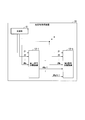
- FIG. 1 is a block diagram of an optical signal receiving apparatus 10 in the first to fourth embodiments of the present invention.
- the optical signal receiving apparatus 10 includes the receiving unit 11 and the first signal separation device 12-1 to the k-th signal separation device 12-k (k is an integer of 2 or more).
- the first signal separation device 12-1 to the k-th signal separation device 12-k will be simply referred to as the signal separation device 12 unless otherwise distinguished.
- the receiving unit 11 receives signals transmitted from respective optical signal transmission devices (not shown). For example, the receiving unit 11 receives N R (N R is an integer of 2 or more) signals.
- the receiving unit 11 outputs the received N R signals to each signal separation device 12.
- the signal separation device 12 separates the input received signal.
- the first signal separation device 12-1 separates a single signal from the input N R signals.
- the first signal separation device 12-1 outputs a signal obtained from the separated signal to the k-th signal separation device 12-k (N R +1 in FIG. 1).
- the k th signal separator 12-k is the sum of N R signals and (k ⁇ 1) signals obtained from the first signal separator to the (k ⁇ 1) signal separator 12 ( N R + k ⁇ 1) signals are input, and the signal k is separated from the received signal.
- the signal separation device (j-th signal separation device (1 ⁇
- the case of j ⁇ k) is the same as the k-th signal separation device 12-k (the same applies to the first to fourth embodiments described below). That is, the j-th signal separation device 12-j includes N R signals and (j ⁇ 1) signals obtained from the first signal separation device to the (j ⁇ 1) -th signal separation device 12. A total of (N R + j ⁇ 1) signals are input, and signal j is separated from the received signal.
- N R + j ⁇ 1 the details of the signal separation device will be described.
- FIG. 2 is a schematic block diagram showing a functional configuration of the optical signal receiving apparatus 10 in the first embodiment.
- illustration of the receiving part 11 is abbreviate
- processing of the signal separation device 12 will be described using the first signal separation device 12-1 and the second signal separation device 12-2 among the signal separation devices 12 included in the optical signal receiving device 10.
- the description will be made assuming that the components of the reception signal y (that is, received N R signals) are sorted in descending order of SINR.
- the first signal separation device 12-1 includes a spatial filtering unit 13-1, a temporary determination signal output unit 14-1, and a weighting factor update unit 15-1.
- the spatial filtering unit 13-1 receives the N R signals output from the receiving unit 11, and separates the equalized signal by multiplying the input N R signals by a weighting factor.
- the weighting factor is a factor used for signal separation, and may be preset as an initial value or may be zero. The weighting factor is updated each time the processing is performed.
- the equalized signal separated by the processing of the spatial filtering unit 13-1 is x 1 ⁇ .
- the temporary determination signal output unit 14-1 receives the equalized signal x 1 ⁇ obtained by the processing of the spatial filtering unit 13-1, and determines the input equalized signal x 1 ⁇ . judgment signal x 1 - output as a second signal separator 12-2.
- the weighting factor updating unit 15-1 receives the equalization signal x 1 ⁇ obtained by the processing of the spatial filtering unit 13-1, and updates the weighting factor w T 1 based on the input equalization signal x 1 ⁇ . .
- the weighting factor w T 1 updated by the weighting factor updating unit 15-1 is referred to as a first weighting factor.
- the second signal separation device 12-2 includes a spatial filtering unit 13-2, a temporary determination signal output unit 14-2, and a weighting factor update unit 15-2.
- Spatial filtering section 13-2, and the N R signals output from the receiving unit 11 a first provisional decision signal x 1 output from the first signal separator 12-1 - the sum of the (N R +1) Signals are input, and the input (N R +1) signals are separated by multiplying the weighting coefficient vector by the equalization signal.
- the equalized signal separated by the processing of the spatial filtering unit 13-2 is x 2 ⁇ .
- the temporary determination signal output unit 14-2 receives the equalized signal x 2 ⁇ obtained by the processing of the spatial filtering unit 13-2, and determines the received equalized signal x 2 ⁇ , and the second determination result is temporary decision signal x 2 - the output to the subsequent stage of the signal separating unit 12.
- the weighting factor updating unit 15-2 receives the equalized signal x 2 ⁇ obtained by the processing of the spatial filtering unit 13-2, and updates the weighting factor w T 2 based on the received equalized signal x 2 ⁇ . .
- the weighting factor w T 2 updated by the weighting factor updating unit 15-2 is referred to as a second weight factor.
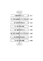
- FIG. 3 is a flow chart for explaining the flow of processing of the optical signal receiving apparatus 10 in the first embodiment.
- the processing of the signal separation device 12 will be described using the first signal separation device 12-1 and the second signal separation device 12-2 among the signal separation devices 12 included in the optical signal receiving device 10.
- the spatial filtering unit 13-1 inputs N R signals output from the receiving unit 11 (step S101).
- the spatial filtering unit 13-1 separates the equalized signal by multiplying the input N R signals by the first weighting factor w T 1 output from the weighting factor updating unit 15-1 (step S102). ).
- the spatial filtering unit 13-1 outputs the separated equalized signal x 1 ⁇ to the temporary determination signal output unit 14-1.
- the temporary determination signal output unit 14-1 receives the equalized signal x 1 ⁇ output from the spatial filtering unit 13-1.
- the temporary determination signal output unit 14-1 determines the input equalized signal x 1 ⁇ , and outputs the determination result as the first temporary determination signal x 1 - to the second signal separation device 12-2 (step S103).
- the process of determination means determining a likely signal as an equalized signal.
- the process of determination will be described by taking an example.
- the determination of x 1 ⁇ is considered using a QPSK (Quadrature Phase Shift Keying) modulation signal.
- x 1 ⁇ can be divided into real components x r1 ⁇ and imaginary components x i1 ⁇ as follows.
- x 1 ⁇ x r1 ⁇ + 1 j * x i1 ⁇
- x i1 ⁇ > 0 it is determined as 1 (or 0)
- x i1 ⁇ ⁇ 0 or x i1 ⁇ 0, it is determined as 0 (or 1).
- x r1 ⁇ is determined and x i1 ⁇ in one bit each, a total of 2 bits first temporary decision signal x 1 is a provisional decision result - output as.
- the weighting factor updating unit 15-1 also receives the equalized signal x 1 ⁇ output from the spatial filtering unit 13-1.
- the weight coefficient update unit 15-1 updates the first weight coefficient w T 1 using an adaptive algorithm such as LMS method, RLS method, CMA method, and the input equalized signal x 1 ⁇ (step S104). For example, in the case of using the LMS method, the weighting factor updating unit 15-1 updates the first weighting factor w T 1 as shown in the following equation (10) with the error e 1 and the step size parameter ⁇ .
- * represents a complex conjugate signal
- a first provisional decision signal x 1 output from the first signal separator 12-1 - the sum of the (N R +1) Signals are input (step S105).
- the spatial filtering unit 13-2 separates the equalized signal by multiplying the input (N R +1) signals by the second coefficient w T 2 output from the weighting coefficient update unit 15-2. (Step S106).
- the spatial filtering unit 13-2 outputs the separated equalized signal x 2 ⁇ to the temporary determination signal output unit 14-2.
- the temporary determination signal output unit 14-2 receives the equalized signal x 2 ⁇ output from the spatial filtering unit 13-2.
- the temporary determination signal output unit 14-2 determines the input equalized signal x 2 ⁇ , and outputs the determination result as the second temporary determination signal x 2 - to the signal separation device 12 in the subsequent stage (step S107).
- the weighting factor updating unit 15-2 also receives the equalized signal x 2 ⁇ output from the spatial filtering unit 13-2.
- the weight coefficient update unit 15-2 updates the second weight coefficient w T 2 using an adaptive algorithm such as LMS method, RLS method or CMA method, and the input equalized signal x 2 ⁇ (step S108). For example, the weighting factor updating unit 15-2 updates the second weighting factor w T 2 as the following equation (11), with an error e 2 .
- the spatial filtering unit 13-k of the k-th signal separation apparatus 12-k of the next stage is the (k-1) -th signal separation apparatus 12- (of the previous stage).
- the (k ⁇ 1) temporary determination signal x (k ⁇ 1) ⁇ generated from the signal extracted in k ⁇ 1) is added. That is, in the spatial filtering unit 13-k of the k-th signal separation device 12-k, N R received signals and the (k ⁇ 1) th signal separation device 12- (k-) from the first signal separation device 12-1 are used.
- a signal vector consisting of (N R + k-1) components is input by adding up (k-1) signal components determined in 1) and (k-1) components, and the signal k is separated. Therefore, it becomes possible to separate multiplexed signals with high accuracy.
- the signal detection performance of the successive interference canceller largely depends on the generation accuracy of the replica signal.
- changes in phase and amplitude in the propagation path, that is, channel information are input before the spatial filtering unit 13-1. It is required to obtain high accuracy.
- the weighting factor of the interference component of an arbitrary stream included in each received signal is adaptively adjusted in the weighting factor update unit, and it becomes unnecessary to estimate channel information in advance, and interference It is possible to remove the components.
- FIG. 4 is a schematic block diagram showing a functional configuration of the optical signal receiving device 10a in the second embodiment.
- processing of the signal separation device 12a will be described using the first signal separation device 12a-1 and the second signal separation device 12a-2 among the signal separation devices 12a included in the optical signal receiving device 10a.
- the components of the reception signal y are sorted in the descending order of SINR.
- the first signal separation device 12a-1 includes a spatial filtering unit 13-1, a temporary determination signal output unit 14a-1, and a weighting factor update unit 15-1.
- the first signal separation device 12a-1 is different from the first signal separation device 12-1 in that the first signal separation device 12a-1 includes a temporary determination signal output unit 14a-1 instead of the temporary determination signal output unit 14-1.
- the other configuration of the first signal separation device 12a-1 is the same as that of the first signal separation device 12-1. Therefore, the entire description of the first signal separation device 12a-1 will be omitted, and the temporary determination signal output unit 14a-1 will be described.
- the temporary determination signal output unit 14a-1 receives the equalization signal x 1 ⁇ obtained by the processing of the spatial filtering unit 13-1, and receives the first temporary determination signal x 1 obtained from the input equalization signal x 1 ⁇ . - output to the second signal separator 12-2.
- the temporary determination signal output unit 14a-1 includes a log likelihood ratio calculation unit 141-1, a deinterleaver 142-1, an error correction decoding unit 143-1, an interleaver 144-1, and a mapping circuit 145-1.
- Log-likelihood ratio calculation unit 141-1 receives equalized signal x 1 ⁇ obtained by the process of spatial filtering unit 13-1 and receives received signal for each bit constituting equalized signal x 1 ⁇ Calculate the log-likelihood ratio between the probability that 0 was transmitted and the probability that 1 was transmitted when y was received.
- the log likelihood ratio calculation unit 141-1 outputs the calculated log likelihood ratio to the deinterleaver 142-1.
- the deinterleaver 142-1 rearranges the log likelihood ratio output from the log likelihood ratio calculation unit 141-1 for each bit.
- the deinterleaver 142-1 outputs the rearranged log likelihood ratio to the error correction decoding unit 143-1.
- the error correction decoding unit 143-1 decodes using the same error correction code as the error correction code used on the optical signal transmission device side.
- the error correction code in the present embodiment is not limited to a specific error correction code such as a Hamming code, a BCH code, an LDPC (Low Density Parity Check) code and a convolutional code, for example, and any error correction code may be used. It is also good.
- the interleaver 144-1 rearranges each bit of the signal output from the error correction decoding unit 143-1 in the same manner as the optical signal transmission device side.
- Mapping circuit 145-1 first by mapping the bits of the rearranged in each symbol temporary decision signal x 1 - to generate.
- the mapping circuit 145-1 outputs the generated first temporary determination signal x 1 - to the second signal separation device 12-2.
- the second signal separation device 12a-2 includes a spatial filtering unit 13-2, a temporary determination signal output unit 14a-2, and a weighting factor update unit 15-2.
- the second signal separation device 12a-2 differs from the second signal separation device 12-2 in that it includes a temporary determination signal output unit 14a-2 in place of the temporary determination signal output unit 14-2.
- the other configuration of the second signal separation device 12a-2 is the same as that of the second signal separation device 12-2. Therefore, the entire description of the second signal separation device 12a-2 will be omitted, and the temporary determination signal output unit 14a-2 will be described.
- the temporary determination signal output unit 14a-2 receives the equalized signal x 2 ⁇ obtained by the processing of the spatial filtering unit 13-2, and receives a second temporary determination signal x 2 obtained from the input equalized signal x 2 ⁇ .
- the signal ⁇ is output to the signal separation device 12 in the subsequent stage.
- the temporary determination signal output unit 14a-2 includes a log likelihood ratio calculation unit 141-2, a deinterleaver 142-2, an error correction decoding unit 143-2, an interleaver 144-2, and a mapping circuit 145-2.
- the temporary determination signal output unit 14a-1 performs the processing of the log likelihood ratio calculation unit 141-2, the deinterleaver 142-2, the error correction decoding unit 143-2, the interleaver 144-2, and the mapping circuit 145-2. Description is omitted because the same processing as that of the functional unit with the same name is performed.
- FIG. 4 is described using two signal separation devices 12a, in the case of the third signal separation device 12a-3, N R signals output from the receiving unit 11 and the first signal separation are used.
- the first output from the unit 12a-1 temporary decision signal x 1 - and, second temporary decision signal x 2 output from the second signal separator 12a-2 - total (N R +2) number of signals that the It is input.
- the spatial filtering unit 13 separates the first signal separation device 12a-1 to the (k-1) th signal separation device 12a- (k-1).
- a signal consisting of (N R + k-1) components in total of the (k-1) determined signal components and the N R signals output from the receiving unit 11 is input, and Do separation.
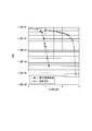
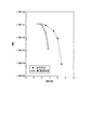
- FIG. 5 shows the comparison results of bit error rates of the conventional method and the second embodiment. From FIG. 5, it can be seen that by applying the second embodiment, a gain of Eb / N0, that is, about 3.5 dB as an SNR gain is obtained at a bit error rate of 10 -3 .
- the optical signal receiving apparatus 10a configured as described above, the same effect as that of the first embodiment can be obtained.
- the optical signal receiving apparatus 10a performs error correction when generating the temporary determination signal. This makes it possible to separate multiplexed signals with higher accuracy than in the first embodiment.
- the signal detection performance of the successive interference canceller depends on the generation accuracy of the replica signal. If the equalization signal x 1 ⁇ output from the spatial filtering unit 13-1 is tentatively determined without passing through the error correction decoding unit 143-1, an error is likely to be included, and thus the signal detection performance of the successive interference canceller is likely to deteriorate.
- the equalization signal x 1 ⁇ output from the spatial filtering unit 13-1 is tentatively determined through the error correction decoding unit 143-1, the effect of the error correction decoding and the effect of the interleaver are combined, and the bit error rate If the error threshold value is equal to or less than the error threshold value, it is possible to enhance the generation accuracy of the replica signal and consequently to improve the signal detection performance of the successive interference canceller.
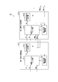
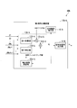
- FIG. 6 is a schematic block diagram showing a functional configuration of the k-th signal separation device 12b-k in the optical signal reception device 10b according to the third embodiment. Also in the present embodiment, in order to simplify the description, it is assumed that the components of the reception signal y are sorted in the descending order of SINR.
- the k-th signal separation device 12b-k includes a spatial filtering unit 13b-k, a temporary determination signal output unit 14-k, a weighting factor update unit 15b-k, and a phase noise estimation unit 16-k.
- the k-th signal separation device 12b-k includes a spatial filtering unit 13b-k and a weighting coefficient updating unit 15b-k instead of the spatial filtering unit 13-k and the weighting coefficient updating unit 15-k, and phase noise estimation is newly performed.
- the other configuration of the k-th signal separator 12b-k is similar to that of the k-th signal separator 12-k. Therefore, the entire description of the k-th signal separation device 12b-k is omitted, and the spatial filtering unit 13b-k, the weighting factor update unit 15b-k, and the phase noise estimation unit 16-k will be described.
- the spatial filtering unit 13b-k outputs the N R signals output from the receiving unit 11 and the first signal separation device 12-1 to the (k-1) th signal separation device 12b- (k-1). from the (k-1) temporary decision signal x (k-1) - - is first temporary decision signal x 1 and to a total of (N R + k-1) inputting a number of signals.
- the spatial filtering unit 13 b-k multiplies the input signal (N R + k ⁇ 1) by the kth weight coefficient w T k output from the weight coefficient update unit 15 b-k to obtain an equalized signal.
- the spatial filtering unit 13b-k separates the equalized signal x k ⁇ based on the following equation (12).
- Equation (12) the multiplication of the first term is performed by the first multiplication unit 131-k and the multipliers 131a-k, and the multiplication of the second term is performed by the second multiplication unit 132-k.
- w T k1 is an N R ⁇ 1 column vector
- w T k2 is a (k ⁇ 1) ⁇ 1 column vector.
- ⁇ k represents the phase noise estimated for the signal k by the phase noise estimation unit 16-k.
- the spatial filtering unit 13b-k includes a first multiplication unit 131-k, a multiplier 131a-k (third multiplication unit), a second multiplication unit 132-k, and an adder 133-k (addition unit).
- the first multiplication unit 131-k receives N R signals that are received signals among the (N R + k-1) input signals and the k th weight coefficient w output from the weight coefficient update unit 15 b-k. Multiply by T k1 .
- the first multiplication unit 131-k multiplies the N R received signals by a coefficient.
- the multipliers 131a-k multiply the output signal output from the first multiplication unit 131-k by the phase noise estimated by the phase noise estimation unit 16-k.
- the second multiplier 132-k is configured to receive (k ⁇ 1) signals of the (N R + k ⁇ 1) input signals and the k th weight coefficient w T output from the weight coefficient update unit 15 b-k. Multiply by k2 .
- the (k-1) signals input to the second multiplication unit 132-k are output from the first signal separator 12-1 to the (k-1) th signal separator 12b- (k-1).
- the second multiplier 132-k multiplies coefficients by (k-1) signals.
- the adder 133-k adds the multiplication result obtained by the multipliers 131a-k and the multiplication result obtained by the second multiplication unit 132-k to generate an equalized signal x k ⁇ .
- the adder 133-k outputs the generated equalized signal x k ⁇ to the temporary determination signal output unit 14-k, the weight coefficient update unit 15b-k, and the phase noise estimation unit 16-k.
- the phase noise estimation unit 16-k receives the equalized signal x k ⁇ obtained by the processing of the spatial filtering unit 13b-k, and estimates phase noise from the input equalized signal x k ⁇ .
- phase noise estimation unit 16-k is not particularly limited, and a digital phase locked loop method, a Viterbi-Viterbi algorithm, or the like can be used. Also, the phase noise estimation unit 16-k may use the output from the optical phase locked loop.
- the weighting factor updating unit 15b-k receives the equalized signal x k ⁇ output from the spatial filtering unit 13b-k.
- the weighting factor updating unit 15b-k uses an adaptive algorithm such as LMS method, RLS method or CMA method, and the input equalized signal x k ⁇ , and the error is ek as shown in the following equation (13) k Weight coefficient w T k is updated.
- the signal detection performance of the successive interference canceller largely depends on the generation accuracy of the replica signal.
- phase noise due to phase shift or frequency shift of the light source on the transmission side and the local light on the reception side is superimposed on the reception signal.
- the conventional successive interference canceller is applied to optical communication, in order to improve the generation accuracy of the replica signal, the change in phase and amplitude in the propagation path, that is, the channel information is high before the input of the spatial filtering unit 13b-k. Not only the accuracy needs to be determined, but also the phase noise needs to be determined with high accuracy.
- the phase noise estimation unit 16-k and the spatial filtering unit 13b-k it is not necessary to estimate channel information and estimate phase noise in advance.
- the temporary determination signal output unit 14-k included in the kth signal separation device 12b-k may be replaced with one having an error correction function. That is, as in the second embodiment, the temporary determination signal output unit 14-k may include a log likelihood ratio calculation unit, a deinterleaver, an error correction decoding unit, an interleaver, and a mapping circuit.
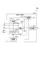
- FIG. 7 is a schematic block diagram showing a functional configuration of the k-th signal separation device 12c-k in the optical signal reception device 10c according to the fourth embodiment. Also in the present embodiment, in order to simplify the description, it is assumed that the components of the reception signal y are sorted in the descending order of SINR.
- the k-th signal separation device 12c-k includes a spatial filtering unit 13c-k, a temporary determination signal output unit 14-k, a weighting factor update unit 15c-k, and a phase noise estimation unit 16-k.
- the k-th signal separation device 12c-k is different from the k-th signal separation device in that it includes a spatial filtering unit 13c-k and a weighting coefficient updating unit 15c-k instead of the spatial filtering unit 13b-k and the weighting coefficient updating unit 15b-k.
- the other configuration of the k-th signal separator 12c-k is similar to that of the k-th signal separator 12b-k. Therefore, the entire description of the k-th signal separation device 12c-k is omitted, and the spatial filtering unit 13c-k and the weight coefficient update unit 15c-k will be described.
- the spatial filtering unit 13c-k outputs the N R signals output from the receiving unit 11 and the first signal separation device 12-1 to the (k-1) th signal separation device 12c- (k-1). from the (k-1) temporary decision signal x (k-1) - - is first temporary decision signal x 1 and to a total of (N R + k-1) inputting a number of signals.
- the spatial filtering unit 13c-k receives the (N R + k-1) input signals, the k-th weighting coefficient w T k output from the weighting coefficient update unit 15c- k, and the phase noise estimation unit 16-k. Separate the equalized signal by multiplying it with the estimated phase noise. For example, the spatial filtering unit 13c-k separates the equalized signal x k ⁇ based on the following equation (14).
- the weighting factor update unit 15c-k receives the equalized signal x k ⁇ output from the spatial filtering unit 13c-k.
- the weighting factor updating unit 15c-k updates the kth weighting factor w T k using an adaptive algorithm such as LMS method, RLS method, CMA method, and the input equalized signal x k ⁇ .
- the weight coefficient update unit 15c-k updates the kth weight coefficient w T k as shown in the following equation (15).
- the spatial filtering unit 13c-k includes a phase correction unit 134-k, a coefficient multiplication unit 135-k, a multiplier 136-k, and an operator 137-k.
- the phase correction unit 134-k uses the (k ⁇ 1) signals of the input (N R + k ⁇ 1) signals and the phase noise correction obtained by the computing unit 137-k to obtain a phase. Make corrections. For example, the phase correction unit 134-k performs phase correction based on the following equation (16).
- phase correction unit 134-k multiplies the signal of #N R +1 output from the first signal separation device 12-1 by the phase noise correction to obtain #N R +1. Perform phase correction of the signal. Further, the phase correction unit 134-k multiplies the signal of #N R + (k-1) output from the (k-1) th signal separation device 12c-(k-1) by the phase noise correction. Thus, phase correction of the signal of #N R + (k ⁇ 1) is performed. The phase correction unit 134-k outputs (k ⁇ 1) signals after phase correction to the coefficient multiplication unit 135-k.
- the (k-1) signals input to the phase correction unit 134-k are output from the first signal separation device 12c-1 to the (k-1) th signal separation device 12c- (k-1).
- Coefficient multipliers 135-k are entered (N R + k-1) and the N R signals of the number of signals, after the phase correction (k-1) and the number of signals, the weighting factor updating unit 15c-k And the k-th weighting factor w T k output from The multiplier 136-k generates an equalized signal x k ⁇ by multiplying the output signal output from the coefficient multiplying unit 135-k and the phase noise estimated by the phase noise estimating unit 16-k.
- the multiplier 136-k outputs the generated equalized signal x k ⁇ to the temporary determination signal output unit 14-k, the weight coefficient update unit 15c-k, and the phase noise estimation unit 16-k.
- optical signal receiving device 10c configured as described above, the same effects as those of the first embodiment and the second embodiment can be obtained.
- the temporary determination signal output unit 14-k included in the kth signal separation device 12c-k may be replaced with one having an error correction function. That is, as in the second embodiment, the temporary determination signal output unit 14-k may include a log likelihood ratio calculation unit, a deinterleaver, an error correction decoding unit, an interleaver, and a mapping circuit.
- Fifth Embodiment 8 and 9 are schematic block diagrams showing the functional configuration of a signal separation device provided in the optical signal reception device in the fifth embodiment.
- the optical signal receiving apparatus of this embodiment is different from the first signal demultiplexing apparatus 12-1 and the k-th signal demultiplexing apparatus 12-k shown in FIG. 1 in the first signal demultiplexing apparatus 12d-1 and the k-th signal demultiplexing apparatus
- the configuration is different from that of the optical signal receiving apparatus according to the first embodiment in that 12d-k is provided.
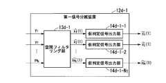
- FIG. 8 is a schematic block diagram showing the functional configuration of the first signal separation device 12d-1
- FIG. 9 is a schematic block diagram showing the functional configuration of the k-th signal separation device 12d-k.
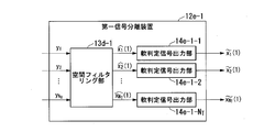
- First signal separator 12d-1 includes a spatial filtering unit 13d-1 temporary decision signal output unit 14d-1-1 ⁇ 14d-1- N T.
- the k signal separator 12d-k includes a spatial filtering unit 13d-k and the temporary judgment signal output unit 14d-k-1 ⁇ 14d- k-N T.
- Each of the spatial filtering unit 13d-1 and the spatial filtering unit 13d-k includes N T spatial filtering units.
- Received signal sequence y1 ⁇ yN R ( “1" and “N R” is subscript) is input to the spatial filtering unit 13d-1 of the first signal separator 12d-1.
- the spatial filtering unit 13d-1 multiplies the received signal sequence y1 to yN R by a weighting factor to obtain an equalized output sequence x1 ⁇ (1) to x N T ⁇ (1) (equalized signal) ("1" and "N”).
- T outputs a subscript.
- the number in parentheses (in this case, "1") represents the number of the signal separation device.
- the temporary determination signal output units 14d-1-1 to 14d-1-N T receive equalized output sequences x1 ⁇ (1) to xN T ⁇ (1), respectively, and temporarily determine the input signals to make a determination. It outputs the result as a temporary judgment signal sequence x1 ⁇ (1) ⁇ xN T ⁇ (1) ( ⁇ are subjected on the "x1" and "xN T").
- temporary determination means determining a signal that is likely to be an equalized signal. Note that an example of the determination process is as described in the first embodiment.
- a received signal sequence y1 ⁇ yN R, temporary decision signal sequence x1 ⁇ (1) ⁇ xN T ⁇ (1) , the second signal separator 12d-2 illustrated in FIG. 9 (in this case, k in FIG. 9 2) is input to the spatial filtering unit 13d-2.
- Spatial filtering unit 13d-2 multiplies the weighting factor ⁇ received signal sequence y1 ⁇ yN R and the temporary decision signal sequence x1 (1) ⁇ xN T ⁇ (1), the equalization output sequence x1 ⁇ (2) ⁇ xN Output T ⁇ (2).
- the temporary determination signal output units 14d-2-1 to 14d-2-N T receive the equalized output series x1 ⁇ (2) to xN T ⁇ (2), temporarily determine the input signal, and determine the determination result.
- the temporary determination signal sequences x1 to (2) to xN T to (2) are output.
- k corresponds to the number of repetitions of the signal detection process, and is a number that can be set by the business operator.
- the upper limit value of k is set to P (“predetermined number of times”).
- the above processing is P stages (i.e., the P signal separator 12d-P) performed until, finally, the signal sequence x1 ⁇ ⁇ xN T ⁇ is output.
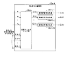
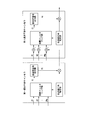
- FIG. 10 is a schematic block diagram showing an example of a functional configuration of a (k-i) spatial filtering unit 13d-k-i constituting the spatial filtering unit 13d-k (i is an integer of 1 or more and NT or less) .
- the (ki) spatial filtering unit 13d-ki performs an i-th signal detection process.
- the (ki) spatial filtering unit 13d-k-i includes a first multiplication unit 131d-k, a multiplier 131da-k (third multiplication unit), a second multiplication unit 132d-k, and an adder 133d.
- -K additional unit
- weight coefficient update unit 15d-k and phase noise estimation unit 16d-k.
- the spatial filtering unit 13d-k in the k-th signal separation device 12d-k shown in FIG. 9 is configured by combining NT (k-i) spatial filtering units.
- the first multiplication unit 131 d-k multiplies the received signal sequence y 1 to y N R by the weighting coefficient output from the weighting coefficient update unit 15 d-k, and outputs the multiplication result.
- the second multiplying unit 132d-k multiplies the temporary decision signal sequence x1 ⁇ (k-1) ⁇ xN T ⁇ (k-1) weighting factor output from the weighting factor updating unit 15d-k with respect to the multiplication Output the result.
- the multiplier 131da-k multiplies the multiplication result output from the first multiplier 131d-k by the term exp (-1j * ⁇ ) corresponding to the phase noise output from the phase noise estimator 16d-k.
- the adder 133d-k adds the multiplication result output from the multiplier 131da-k and the multiplication result output from the second multiplication unit 132d-k, and outputs an equalized output sequence xi ⁇ (k). .
- the phase noise estimation unit 16d-k and the weight coefficient update unit 15d-k create training data based on the equalized output sequence xi ⁇ (k), and estimate phase noise and weight coefficients according to a predetermined algorithm. Update the As a predetermined algorithm, for example, the Viterbi-Viterbi method is used in the phase noise estimation unit 16d-k, and the probability gradient method is used in the weight coefficient update unit 15d-k.
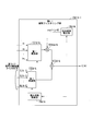
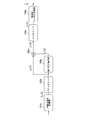
- FIG. 11 is a schematic block diagram showing another example of the functional configuration of the (ki) spatial filtering unit 13d-k-i configuring the spatial filtering unit 13d-k.
- the (k ⁇ ) spatial filtering unit illustrated in FIG. 11 does not include the first multiplication unit 131 d-k, the multiplier 131 da-k, the second multiplication unit 132 d-k, and the adder 133 d-k,
- the configuration is different from the (ki) spatial filtering unit shown in FIG. 10 in that the correction unit 134d-k, the coefficient multiplying unit 135d-k, the multiplier 136d-k, and the computing unit 137d-k are provided.
- Arithmetic units 137 d-k correspond to phase noise correction (exp (1 j * ⁇ ) in FIG. 11) from phase noise (corresponding to exp ( ⁇ 1 j * ⁇ ) in FIG. 11) estimated by phase noise estimation unit 16 d-k Ask for).
- the phase correction unit 134d-k multiplies the temporary determination signal sequence x1 to (k-1) to xN T to (k-1) by the term of exp (1j * ⁇ ) corresponding to the phase noise correction.
- Coefficient multiplying unit 135d-k to the temporary decision signal sequence and the received signal sequence y1 ⁇ yN R after the phase noise correction, multiplied by the weighting factor output from the weighting factor updating unit 15d-k, outputs a multiplication result Do.
- the multiplier 136d-k multiplies the multiplication result output from the coefficient multiplying unit 135d-k by the term of exp (-1j * ⁇ ) corresponding to the phase noise estimated by the phase noise estimating unit 16d-k. And output an equalized output sequence xi ⁇ (k).
- the weighting factor updating unit 15d-k and the phase noise estimating unit 16d-k perform the same processing as the functional units of the same name illustrated in FIG. 10, and thus the description thereof is omitted here.
- the temporary determination signal output units 14d-1-1 to 14d-1-N T and the temporary determination signal output units 14d-k-1 to 14d-k-N T may be replaced with those having an error correction function. That is, each of these temporary determination signal output units may be provided with a log likelihood ratio calculation unit, a deinterleaver, an error correction decoding unit, an interleaver, and a mapping circuit as in the second embodiment.
- FIG. 12 is a schematic block diagram showing the functional configuration of the first signal separation device 12e-1
- FIG. 13 is a schematic block diagram showing the functional configuration of the k-th signal separation device 12e-k.
- These signal separation devices are the temporary determination signal output units 14d-1-1 to 14d-1-N T in the first signal separation device 12d-1 and the k-th signal separation device 12d-k in the fifth embodiment, and The soft decision signal output units 14e-1-1 to 14e-1-N T and the soft decision signal output units 14e-k-1 to 15e instead of the temporary decision signal output units 14d-k-1 to 14d-k-N T
- the configuration is different from that of the signal separation apparatus according to the fifth embodiment in that 14e-k-N T is provided.
- Soft decision signal output units 14e-1-1 to 14e-1-N T and soft decision signal output units 14e-k-1 to 14e-k-N T are respectively spatial filtering unit 13d-1 and spatial filtering unit 13d.
- the equalized output series x1 ⁇ (1) to xN T ⁇ (1) and equalized output series x1 ⁇ (k) to xN T ⁇ (k) output from -k are input.
- the soft decision signal output units 14e-1-1 to 14e-1-N T and 14e-k-1 to 14e-k-N T are error correction codes added in advance to the input equalized output sequence.
- the likelihood information of transmission signal information such as transmission bits and transmission symbols is calculated using parity etc., soft decision symbols are generated based on likelihood information, and the generated soft decision symbols are respectively equalized output sequence x 1 Output as ⁇ (1) to xN T ⁇ (1) and equalized output series x1 ⁇ (k) to xN T ⁇ (k).
- the other signal input / output relationships and the processing of each functional unit are the same as in the fifth embodiment, and thus the description thereof is omitted here.
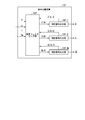
- FIG. 14 is a schematic block diagram showing a functional configuration of each soft decision signal output unit in the present embodiment.
- Each soft decision signal output unit includes a log likelihood ratio calculator 141 e, a deinterleaver 142 e, an error correction decoder 143 e, an interleaver 144 e, a soft decision symbol generator 146 e, and a subtractor 147 e.
- the log likelihood ratio calculation unit 141 e receives the equalized output sequence xi ⁇ (k) output from the spatial filtering unit 13 d-1 or the spatial filtering unit 13 d-k and inputs each of the bits constituting the equalized output sequence 0 calculates the log likelihood ratio L a (b i t) between the transmission probabilities and the probability of 1 is transmitted.
- b i t represents the t-th bit of the i-th transmission signal sequence.
- the log likelihood ratio calculation unit 141 e outputs the calculated log likelihood ratio L a (b i t ) to the deinterleaver 142 e .
- the deinterleaver 142 e rearranges the input log likelihood ratio L a (b i t ) bit by bit, and outputs L a (c i t ).
- c i t is a binary sequence in which b i t is rearranged.
- the deinterleaver 142 e outputs the rearranged log likelihood ratio L a (c i t ) to the error correction decoding unit 143 e and the subtractor 147 e.
- Error correction decoding section 143e based on the same error correction code and the error correction code used in optical signal transmission apparatus, using an appropriate decoding method, for each bit a posteriori log likelihood ratio L p (c i t Calculate).
- c i t represents the t-th bit of the i-th transmission signal sequence.
- the error correction code in the present embodiment is not limited to a specific error correction code such as a Hamming code, a BCH code, an LDPC code, and a convolutional code, and any correction code may be used.
- the subtractor 147 e subtracts L a (c i t ) that is also an input to the error correction decoding unit 143 e from the posterior log likelihood ratio L p (c i t ) output from the error correction decoding unit 143 e.
- the external log likelihood ratio L e (c i t ) is calculated as shown in the following equation.
- L e (c i t ) L p (c i t ) -L a (c i t ) (17)
- the subtractor 147 e outputs the outer log likelihood ratio L e (c i t ) to the interleaver 144 e .
- Interleaver 144e outputs the external log likelihood ratio L e (c i t) rearranges the place and L e (b i t).
- L e (b i t ) is input to the soft decision symbol generator 146 e .
- Soft decision symbol generator 146e generates the soft decision symbol sequence b i t ⁇ from the input L e (b i t).
- FIG. 15 is a schematic block diagram showing a functional configuration of a signal separation device provided in the optical signal receiving device in the seventh embodiment.
- Signal separating apparatus 12f of this embodiment includes a spatial filtering section 13f and the determination signal output unit 14f-1 ⁇ 14f-N T .
- the spatial filtering unit 13 f has the same function as the spatial filtering unit described in the fifth embodiment or the spatial filtering described in the sixth embodiment.
- the determination signal output units 14f-1 to 14f- NT are the temporary determination signal output units or the soft determination signal output units in the above-described embodiment.
- the signal separation device 12f of the present embodiment is based on repetitive processing and has a feedback structure.
- the upper limit value P of the number of times the signal detection process is repeated is set.
- the signal detection processing one time is received sequence y1 ⁇ yN R is input to the spatial filtering section 13f.
- the spatial filtering unit 13f does not use the signals fed back from the determination signal output units 14f-1 to 14f- NT .
- Spatial filtering unit 13f multiplies the weight coefficient in the reception signal sequence y1 ⁇ yN R, and outputs an equalized output sequence x1 ⁇ (1) ⁇ xN T ⁇ (1).
- the numbers in parentheses indicate the number of repetitions (in this case, “1” because this is the first signal detection processing).
- determination signal output units 14f-1 to 14f-N T receive equalized output sequences x1 ⁇ (1) to xN T ⁇ (1), respectively, and perform determination on the input equalized output sequence (i.e., determination by the provisional determination signal output unit or the soft decision signal outputting unit described above) is performed, resulting temporary decision signal sequence or soft decision signal sequence determination signal sequence x1 ⁇ (1) ⁇ xN T ⁇ (1) Output to the spatial filtering unit 13f.
- the determination signal sequences x1 to (k-1) to xN T (k to (k) are fed back from the reception signal sequences y1 to yN R and the determination signal output units 14f-1 to 14f-N T -1) is input to the spatial filtering unit 13f.
- the spatial filtering unit 13 f multiplies the received signal sequence y 1 to y N R and the determination signal sequence x 1 to (k ⁇ 1) to xN T to (k ⁇ 1) by a weighting factor to obtain an equalized output sequence x 1 ⁇ (k ) To xN T ⁇ (k).
- Determination signal output units 14f-1 to 14f-N T receive equalized output sequences x1 ⁇ (k) to xN T ⁇ (k), respectively, and perform determination on the input equalized output sequences, The obtained temporary determination signal sequence or soft determination signal sequence is fed back to the spatial filtering unit 13 f.
- the signal separation device 12f is determined signal sequence x1 ⁇ ⁇ xN T outputs ⁇ a.
- FIG. 16 shows the comparison results of bit error rates of the conventional method and the seventh embodiment. It can be seen from FIG. 16 that by applying the seventh embodiment, about 1.5 dB is obtained as the SNR gain (that is, the SNR gain) at a bit error rate of 10 ⁇ 2 .
- the optical signal receiving apparatus has been described as performing mainly the processing in the time domain, but the processing in the time domain in the optical signal receiving apparatus of each embodiment may be replaced with the processing in the frequency domain.
- the optical signal receiving apparatus in each of the above embodiments may be realized on a communication system other than an optical communication system such as a wireless communication system or a satellite communication system.
- the present invention is not limited to the single carrier communication system described above, and the above embodiments may be applied to multicarrier communication systems such as orthogonal frequency division multiplexing (OFDM) and coded spread communication systems such as code division multiplexing access (CDMA).
- OFDM orthogonal frequency division multiplexing
- CDMA code division multiplexing access
- the form can be implemented as well.
- the above-described optical signal receiving apparatus may be realized by a computer.
- a program for realizing the functions of these devices is recorded in a computer readable recording medium, and the program recorded in the recording medium is read by a computer system and executed to realize an optical signal receiving device.
- the computer system includes hardware such as an operating system (OS) and peripheral devices.
- the computer readable recording medium includes portable media such as a flexible disk, a magneto-optical disk, a ROM (Read Only Memory), a CD (Compact Disc) -ROM, and a storage device such as a hard disk built in a computer system. It means that.
- a computer readable recording medium is one that holds a program dynamically for a short time, like a communication line when transmitting a program via a network such as the Internet or a communication line such as a telephone line.
- a volatile memory in a computer system serving as a server or a client in that case may also include one that holds a program for a certain period of time.
- the program may be for realizing a part of the functions described above, and further, the function described above may be realized in combination with a program already recorded in the computer system.
- the optical signal receiving apparatus may be realized using hardware such as a programmable logic device (PLD), a field programmable gate array (FPGA), or a digital signal processor (DSP).
- PLD programmable logic device
- FPGA field programmable gate array
- DSP digital signal processor
- the present invention is applicable to, for example, optical communication. According to the present invention, it is possible to separate multiplexed signals with high accuracy.
- DESCRIPTION OF SYMBOLS 10 Optical signal receiving apparatus 11 ... Reception part 12 ... Signal separation apparatus 12-1, 12a-1, 12d-1 ... 1st signal separation apparatus 12-2, 12a-2 ... 2nd signal separation apparatus 12-k, 12b -K, 12d-k ... k-th signal separation device 12f ... signal separation device 13-1, 13-2, 13b-k, 13d-1, 13d-k, 13f ... spatial filtering unit 131-k, 131d-k ... First multiplication units 131a-k, 131da-k, 136d-k ... multipliers 132-k, 132d-k ... second multiplication units 133-k, 133d-k ...
- adders 134-k, 134d-k ... phase correction The units 135-k, 135d-k ... coefficient multiplication unit 136-k ... multipliers 137-k ... arithmetic units 14-1 to 14-2, 14a-1 to 14a-2, 14a-k, 14d-1-1 to 14d-1-N T, 14d -k-1 ⁇ 14 -K-N T ... temporary decision signal output unit 14e-1-1 ⁇ 14e-1- N T, 14e-k-1 ⁇ 14e-k-N T ... soft decision signal output unit 14f-1 ⁇ 14f-N T ... Judgment signal output units 141-1 to 141-2, 141e ... Log likelihood ratio calculation units 142-1 to 142-2, 142e ...
Abstract
A signal reception device is provided with at least one signal separating device for separating a specific signal from a plurality of reception signals. Each of the at least one signal separating device is provided with: a spatial filtering unit which separates at least one equalization signal; and a determination signal output unit which generates a first determination signal by determining the equalization signal, and which outputs the generated first determination signal. The spatial filtering unit separates at least one equalization signal by multiplying, among a plurality of reception signals and the first determination signal output from the determination signal output unit or a second determination signal output from another signal separating device, at least the plurality of reception signals with a predetermined weighting coefficient.
Description
本発明は、信号を分離する技術に関する。
本願は、2017年4月13日に日本へ出願された特願2017-079870号に基づいて優先権を主張し、その内容をここに援用する。 The present invention relates to techniques for separating signals.
Priority is claimed on Japanese Patent Application No. 2017-079870, filed Apr. 13, 2017, the content of which is incorporated herein by reference.
本願は、2017年4月13日に日本へ出願された特願2017-079870号に基づいて優先権を主張し、その内容をここに援用する。 The present invention relates to techniques for separating signals.
Priority is claimed on Japanese Patent Application No. 2017-079870, filed Apr. 13, 2017, the content of which is incorporated herein by reference.
近年のスマートフォンの普及、高精細動画サービス配信、IoT(Internet of Things)サービスの発展などに伴って、光ネットワークを流れる通信トラヒックは年々増加の一途をたどっている。光ネットワークでは、これまで、伝送路としての光ファイバの構造を変えずに光ネットワークの端局に設置される光通信システム装置の高機能化、光増幅器・光スイッチの導入などにより、増加する通信トラヒック需要に対する対応がなされてきた。
With the spread of smartphones in recent years, high-definition video service delivery, development of IoT (Internet of Things) services, etc., communication traffic flowing through optical networks is increasing year by year. In optical networks, communication has been increased by increasing the functionality of optical communication systems installed at end stations of optical networks without changing the structure of optical fibers as transmission paths, introducing optical amplifiers and optical switches, etc. Response to traffic demand has been made.
現在の大容量光ネットワークの基盤となっている光ファイバは、LAN(Local Area Network)などの近距離向けの局所的なネットワークを除くと、シングルモードファイバが用いられている。シングルモードファイバは、クラッド内に光信号の通路となる単一のコアを持ち、大容量光ネットワークで用いられるC帯やL帯などの波長帯では単一のモードのみをサポートするファイバである。これにより、毎秒数テラビットに達する情報を長距離にわたり安定的に転送する大容量光ネットワークが実現されている。
The optical fiber which is the foundation of the current high capacity optical network is single mode fiber except for local networks for short distance such as LAN (Local Area Network). A single mode fiber is a fiber having a single core in the cladding as a path of an optical signal and supporting only a single mode in a wavelength band such as C band or L band used in a large capacity optical network. As a result, a large-capacity optical network is realized that stably transfers information reaching several terabits per second over long distances.
また、デジタル信号処理技術とコヒーレント送受信技術を組み合わせたデジタルコヒーレント伝送技術が100ギガビット級の光伝送装置に既に導入されている。デジタルコヒーレント伝送技術を用いることにより、光搬送波の振幅と位相に独立に載せた情報を取り出し、伝送中に生じた波形歪を高精度に補正することができる。
Also, digital coherent transmission technology combining digital signal processing technology and coherent transmission / reception technology has already been introduced into 100 gigabit class optical transmission equipment. By using the digital coherent transmission technology, it is possible to take out the information independently loaded on the amplitude and phase of the optical carrier and correct the waveform distortion generated during transmission with high accuracy.
簡単な例として、シングルモードファイバでの直交偏波の2モードを使った偏波多重光伝送を例に挙げる。偏波多重光伝送では、直交関係にある偏波にそれぞれ異なる情報を載せることができる。光伝送路中ではこれらの偏波が複雑に混合する。また、これら偏波モードの直交軸は高速に変動し、光デバイスを使って追従することは一般に困難である。そこで偏波ダイバーシティ構造に対応した受信装置は、混合した偏波多重光信号を受信し、混合した偏波多重光信号をデジタル信号に直し、デジタル信号処理を用いて信号を分離する。上記の処理は、無線通信システムで用いられる2×2MIMO(Multiple-Input Multiple-Output)システムとしてモデル化することができる。分離された信号からは、偏波ごとにそれぞれ情報が取り出され、光信号送受信装置間での通信が確立する。
As a simple example, polarization multiplexing optical transmission using two modes of orthogonal polarization in a single mode fiber is taken as an example. In polarization multiplexing optical transmission, different pieces of information can be carried on polarizations in an orthogonal relationship. In the optical transmission line, these polarizations are mixed in a complicated manner. Also, the orthogonal axes of these polarization modes fluctuate at high speed, and it is generally difficult to track using optical devices. Therefore, a receiver corresponding to the polarization diversity structure receives the mixed polarization multiplexed optical signal, converts the mixed polarization multiplexed optical signal into a digital signal, and separates the signal using digital signal processing. The above process can be modeled as a 2 × 2 Multiple-Input Multiple-Output (MIMO) system used in a wireless communication system. From the separated signals, information is extracted for each polarization, and communication between optical signal transmitting and receiving apparatuses is established.
別の例として、マルチモードファイバでの複数のモードを使ったモード多重光伝送を例に挙げる。モード多重光伝送では、コア径をシングルモードファイバと比較して広げることにより、C帯などの波長帯においても、複数のモードを励起することができ、各モードにそれぞれ異なる情報を載せることができる。モード多重光伝送の場合においても、偏波多重光伝送の場合と同様に、モード多重された光信号は、マルチモードファイバを伝搬中に複雑に混合する。モードダイバーシティ構造に対応した受信装置は、混合したモード多重光信号を受信し、混合したモード多重光信号をデジタル信号に直し、デジタル信号処理を用いて信号を分離する。上記の処理は、NT×NRMIMOシステムとしてモデル化できる。ただし、NTは光信号送信装置の数、NRは光信号受信装置の数を表す。NTおよびNRはいずれも2以上の整数である。また、以下では各光信号送信装置から独立した変調信号がそれぞれ送信されると仮定する。
As another example, mode-multiplexed optical transmission using a plurality of modes in a multimode fiber is taken as an example. In mode-multiplexed optical transmission, a plurality of modes can be excited even in a wavelength band such as C band by broadening the core diameter compared to a single mode fiber, and different information can be loaded in each mode. . Also in the case of mode-multiplexed optical transmission, as in the case of polarization-multiplexed optical transmission, mode-multiplexed optical signals are complexly mixed during propagation of a multimode fiber. A receiver corresponding to the mode diversity structure receives the mixed mode multiplexed optical signal, converts the mixed mode multiplexed optical signal into a digital signal, and separates the signal using digital signal processing. The above process can be modeled as a N T × N R MIMO system. Here, N T represents the number of optical signal transmitters, and N R represents the number of optical signal receivers. N T and N R is an integer of 2 or more any. Also, in the following, it is assumed that modulated signals independent of each other are transmitted from the respective optical signal transmitters.
次に、光信号受信装置が、偏波多重光伝送またはモード多重光伝送のデジタル信号処理で用いる信号分離アルゴリズムについて説明する。なお、以下ではシングルモードファイバでの偏波モードと、マルチモードファイバでの空間モードを、モードという用語で同列に扱う。無線通信MIMOシステムでは、様々な信号分離アルゴリズムが提案されている。例えば、信号分離アルゴリズムとして、空間フィルタリング、干渉キャンセラ、最尤復号などが挙げられる。一般に信号処理規模とモード分離能力はトレードオフの関係にあり、上記の順で信号処理規模が増す代わりに、モード分離能力は向上する。しかしながら、光通信システムでは、無線通信システムと比較して信号の変調速度が非常に速く、伝送路変動への追従性及びリアルタイム処理が求められるため、線形処理の空間フィルタリングが一般に用いられてきた。送信信号をx、受信信号をy、信号に付加される雑音をz、伝送路行列をHとすると、これらは式(1)の関係で結ばれる。
Next, a signal separation algorithm used by the optical signal receiving apparatus in digital signal processing of polarization multiplexing optical transmission or mode multiplexing optical transmission will be described. In the following, the polarization mode in a single mode fiber and the spatial mode in a multimode fiber will be treated in the same line by the term mode. Various signal separation algorithms have been proposed for wireless communication MIMO systems. For example, as signal separation algorithms, spatial filtering, interference canceller, maximum likelihood decoding and the like can be mentioned. In general, the signal processing scale and the mode separation ability are in a trade-off relationship, and the mode separation ability is improved instead of increasing the signal processing scale in the above order. However, in optical communication systems, spatial filtering of linear processing has generally been used because the modulation speed of signals is very fast as compared to wireless communication systems, and tracking with channel variations and real-time processing are required. Assuming that the transmission signal is x, the reception signal is y, the noise added to the signal is z, and the transmission path matrix is H, these are connected in the relationship of equation (1).
空間フィルタリングは、受信信号yに分離行列WTを乗じて送信信号xの等化信号x^(^はxの上に付される)を得る。ここで、Wの上付き添え字Tは転置を表す。MMSE(Minimum Mean Square Error)規範では、式(2)を満たすWTを求める。
The spatial filtering multiplies the received signal y by the separation matrix W T to obtain an equalized signal x ^ (^ is added above x) of the transmitted signal x. Here, the superscript T of W represents transposition. The MMSE (Minimum Mean Square Error) criterion to determine the W T satisfying the formula (2).
式(2)を解くと、WTとして式(3)が得られる。
Equation (3) is obtained as W T by solving equation (2).

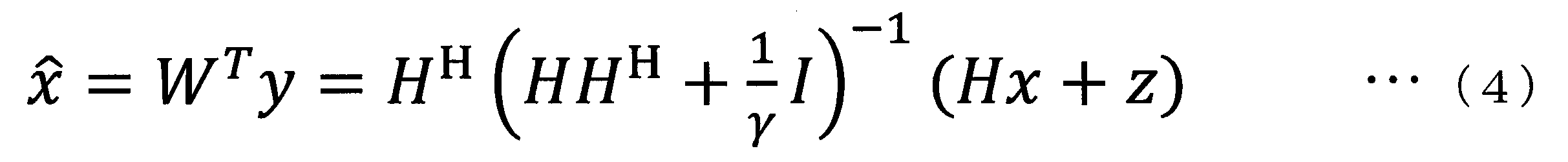
式(3)において、Iは単位行列、γはSNR(Signal-to-noise ratio)、上付きHは複素共役転置を表す。式(3)に示すように、WTを求めるにはHが必要となる。Hはパイロット信号などを用いて求めることもできるが、光通信システムでは伝送路変動への追従性や伝送レートの犠牲を考慮して、適応的にHを求めるLMS(Least Mean Square)法、RLS(Recursive Least Squares)法、CMA(Constant Modulus Algorithm)法などが用いられる。等化信号x^は、式(3)を用いて式(4)のように得られる。
In equation (3), I is an identity matrix, γ is a signal-to-noise ratio (SNR), and a superscript H is a complex conjugate transpose. As shown in equation (3), H is required to determine the W T. H can also be determined using a pilot signal or the like, but in an optical communication system, LMS (Least Mean Square) method for obtaining H adaptively in consideration of the ability to follow transmission line fluctuation and the sacrifice of transmission rate, RLS (Recursive Least Squares) method, CMA (Constant Modulus Algorithm) method, etc. are used. The equalized signal x ^ is obtained as in equation (4) using equation (3).
式(4)の空間フィルタリングを用いることにより、特に偏波多重光通信システムにおいては一定の成果が得られてきた。しかしながら、伝送路行列Hが非ユニタリ性を持ち、雑音が大きな環境下では、等化信号x^には他モードからの残留クロストークが存在する。ここでの非ユニタリ性とは、Hについて式(5)の関係が成立することをいう。
By using the spatial filtering of equation (4), certain results have been obtained, particularly in polarization multiplexing optical communication systems. However, in an environment where the channel matrix H is non-unitary and noise is large, residual crosstalk from other modes exists in the equalized signal x ^. Non-unitaryness here means that the relationship of Formula (5) is materialized about H.
光通信システムの非ユニタリ性は、光増幅器のモードに依存した利得、光デバイスの不完全性、融着点でのコア軸ずれなどが原因で生じる。これらの現象は、シングルモードファイバでは偏波依存損失として知られ、マルチモードファイバではモード依存損失として知られている。以下では、これらの現象をモード依存損失という用語を用いて同列に扱う。
The non-unitary nature of the optical communication system results from the mode dependent gain of the optical amplifier, imperfections in the optical device, core misalignment at the splice point, etc. These phenomena are known as polarization dependent loss in single mode fiber and as mode dependent loss in multimode fiber. In the following, these phenomena will be treated in parallel using the term mode dependent loss.
空間フィルタリングとは別の信号分離アルゴリズムとして、干渉キャンセラがある。干渉キャンセラは並列干渉キャンセラと逐次干渉キャンセラの2種類に分けられるが、以下では逐次干渉キャンセラについて図17を用いて説明する。図17に示す第一逐次干渉キャンセラの空間フィルタリング部は、まず受信信号ベクトルの中からSINR(Signal-to-interference-plus-noise ratio)の最も高いストリームを検出する。SINRの最も高いストリームを決定するには、例えばパイロット信号を用いた方法や、伝送路行列HとSNRから式(6)に基づいて直接SINRを計算する方法が挙げられる。
There is an interference canceller as a signal separation algorithm different from spatial filtering. The interference canceller is divided into two types: parallel interference canceller and sequential interference canceller. In the following, the sequential interference canceller will be described with reference to FIG. The spatial filtering unit of the first successive interference canceller shown in FIG. 17 first detects a stream with the highest signal-to-interference-plus-noise ratio (SINR) from the received signal vectors. In order to determine the highest SINR stream, for example, a method using a pilot signal or a method of calculating SINR directly from the channel matrix H and SNR based on the equation (6) may be mentioned.

式(6)において、ρiはi番目のストリームのSINRである。以下では、簡単のためにSINRの高い順に受信信号yの成分をソートしたものとして説明を行う。すなわち、1番目のストリームのSINRが最も高いものとして説明する。1番目のストリームは式(7)のように検出される。
In equation (6), i i is the SINR of the ith stream. The following description will be made on the assumption that the components of the reception signal y are sorted in descending order of SINR for the sake of simplicity. That is, it is described that the SINR of the first stream is the highest. The first stream is detected as shown in equation (7).
式(7)において、wT
iは、wTのi行目の行ベクトルを表す。第一逐次干渉キャンセラの仮判定信号出力部は、空間フィルタリング部により得られた等化信号x1^(^はx1の上に付す)を判定し、x1
-(-はx1の上に付す)を出力する。その後、第一逐次干渉キャンセラの乗算器により、x1
-と、伝送路行列推定部によって得られたHの1番目の列ベクトルh1とが乗算され、乗算結果h1x1
-が第二逐次干渉キャンセラに入力される。
In equation (7), w T i represents a row vector of the i-th row of w T. Temporary decision signal output portion of the first successive interference canceller, resulting equalized signal x 1 ^ (^ is denoted on the x 1) by spatial filtering unit determines, x 1 - (- Above the x 1 Output). After that, the multiplier of the first successive interference canceller multiplies x 1 − by the first column vector h 1 of H obtained by the channel matrix estimation unit, and the multiplication result h 1 x 1 − is the second It is input to the successive interference canceller.
第二逐次干渉キャンセラでは、2番目にSINRが高いストリームに対しストリーム検出を行う。具体的には、第二逐次干渉キャンセラでは、以下の式(8)のように、受信信号yから1番目のストリーム信号由来の成分h1x1
-を減算する。
The second successive interference canceller performs stream detection on a stream with the second highest SINR. Specifically, in the second successive interference canceller, as in the following equation (8), components derived from the first stream signal from the received signal y h 1 x 1 - subtracts.
また、第二逐次干渉キャンセラでは、式(9)に示すように、Hを1番目の列ベクトルを除いた(NT-1)個の列ベクトルで再構成する。
Also, in the second successive interference canceller, as shown in equation (9), H is reconstructed with (N T -1) column vectors excluding the first column vector.
ストリーム検出は、式(9)で得られたHを用いて分離行列wTを新たに求め、式(7)に基づいて行われる。このように、第二逐次干渉キャンセラ以降の逐次干渉キャンセラでは、式(8)に示す干渉除去、式(9)に示すHの再構成及びストリーム検出を順に行う。この処理を、最後のNT番目のストリーム検出が行われるまで続ける。
The stream detection is performed based on Expression (7) by newly obtaining the separation matrix w T using H obtained by Expression (9). As described above, in the successive interference canceller after the second successive interference canceller, the interference cancellation shown in equation (8), the reconstruction of H shown in equation (9) and the stream detection are sequentially performed. This process is continued until the last N T th stream detection.
逐次干渉キャンセラは、後段にいくに従い、受信信号に含まれるストリーム数が減るため、空間ダイバーシティ効果が得られる。そのため、空間フィルタリングと比較すると高い信号分離性能が得られる。しかしながら、逐次干渉キャンセラは、レプリカ信号を生成するために、伝送路行列Hの生成が必要となる。上述したように、一般に、光通信システムでは、分離行列wTの推定のためにLMS法やRLS法やCMA法などの適応アルゴリズムが用いられる。仮にHを推定すると、伝送レートの犠牲や、Hの推定誤差によるレプリカ信号生成精度の悪化による逐次干渉キャンセラの特性劣化が懸念される。さらに、コヒーレント送受信を行う光通信システムを考えると、受信信号には位相雑音や周波数オフセットが重畳しており、これらもレプリカ信号生成の精度の悪化につながりうる。
In the successive interference canceller, as the number of streams included in the received signal decreases in the later stages, spatial diversity effects can be obtained. Therefore, high signal separation performance can be obtained as compared to spatial filtering. However, the successive interference canceller requires the generation of the channel matrix H in order to generate a replica signal. As described above, generally, in the optical communication system, an adaptive algorithm such as LMS method, RLS method or CMA method is used to estimate the separation matrix w T. If H is estimated, there is a concern that the characteristics of the successive interference canceller may be degraded due to the sacrifice of the transmission rate and the deterioration of the replica signal generation accuracy due to the estimation error of H. Furthermore, considering an optical communication system that performs coherent transmission and reception, phase noise and frequency offset are superimposed on the received signal, which may also lead to deterioration in the accuracy of replica signal generation.
以上をまとめると、空間フィルタリングでは、モード依存損失の影響がSNRの劣化及び残留モード間クロストークとして現れ、これらSNRの劣化及び残留モード間クロストークを完全に取り除くことができない。逐次干渉キャンセラでは、伝送路行列、位相雑音、周波数オフセットなどを別途推定する必要があり、推定精度によっては信号分離性能が低下してしまうという問題があった。モード依存損失は、光信号の伝送距離の拡大に伴って増加するために、光通信システムの長距離化にとって大きな阻害要因となる。
In summary, in spatial filtering, the effect of mode dependent loss appears as SNR degradation and residual mode crosstalk, and these SNR degradation and residual mode crosstalk can not be completely eliminated. In the successive interference canceller, it is necessary to separately estimate a channel matrix, phase noise, frequency offset and the like, and there is a problem that the signal separation performance is degraded depending on the estimation accuracy. Mode-dependent loss increases as the transmission distance of the optical signal increases, which is a major obstacle to increasing the distance of the optical communication system.
上記事情に鑑み、本発明は、高精度で多重信号を分離することができる技術の提供を目的としている。
In view of the above circumstances, the present invention aims to provide a technique capable of separating multiplexed signals with high accuracy.
本発明の一態様は、複数の受信信号から特定の信号を分離する少なくとも1つの信号分離装置を備え、前記少なくとも1つの信号分離装置のそれぞれは、少なくとも1つの等化信号を分離する空間フィルタリング部と、前記等化信号を判定して第1の判定信号を生成し、生成された前記第1の判定信号を出力する判定信号出力部とを備え、前記空間フィルタリング部は、前記複数の受信信号、および、前記判定信号出力部から出力される前記第1の判定信号または他の信号分離装置から出力される第2の判定信号のいずれかのうち、少なくとも前記複数の受信信号と、所定の重み係数とを乗算することによって、前記少なくとも1つの等化信号を分離する信号受信装置である。
上記信号受信装置において、前記少なくとも1つの信号分離装置は複数の信号分離装置であって、前記空間フィルタリング部は、前記複数の受信信号および前記第2の判定信号のうち、少なくとも前記複数の受信信号と、前記所定の重み係数とを乗算することによって、前記少なくとも1つの等化信号として単一の等化信号を分離し、前記判定信号出力部は、前記等化信号として尤もらしい信号を表す仮判定信号を前記第1の判定信号として生成する仮判定信号出力部であり、k(kは2以上の整数)番目の信号分離装置の空間フィルタリング部では、前記複数の受信信号であるNR(NRは2以上の整数)個の受信信号と、一番目の信号分離装置から(k-1)番目の信号分離装置までで得られた前記第2の判定信号としての(k-1)個の仮判定信号との合計(NR+k-1)個の信号を入力し、前記複数の受信信号から信号kを分離するようにしてもよい。 One aspect of the present invention comprises at least one signal separation device for separating a specific signal from a plurality of received signals, and each of the at least one signal separation device is a spatial filtering unit for separating at least one equalization signal. And a determination signal output unit that determines the equalized signal to generate a first determination signal and outputs the generated first determination signal, and the spatial filtering unit further includes the plurality of received signals. And at least the plurality of received signals of the first determination signal output from the determination signal output unit or the second determination signal output from another signal separation device, and a predetermined weight A signal receiving apparatus for separating the at least one equalized signal by multiplying with a coefficient.
In the signal receiving device, the at least one signal separation device is a plurality of signal separation devices, and the spatial filtering unit is configured to receive at least the plurality of received signals among the plurality of received signals and the second determination signal. And the predetermined weighting factor to separate a single equalized signal as the at least one equalized signal, and the determination signal output unit is a temporary signal representing a likely signal as the equalized signal. A temporary determination signal output unit that generates a determination signal as the first determination signal, and the spatial filtering unit of the k-th (k is an integer of 2 or more) signal separation device generates NR N R is the integer of 2 or more) received signals, one-th from the signal separation unit (k-1) th signal obtained by up separator as the second determination signal (k-1) The sum of the temporary decision signal (N R + k-1) Enter the number of signals may be separate signals k from the plurality of received signals.
上記信号受信装置において、前記少なくとも1つの信号分離装置は複数の信号分離装置であって、前記空間フィルタリング部は、前記複数の受信信号および前記第2の判定信号のうち、少なくとも前記複数の受信信号と、前記所定の重み係数とを乗算することによって、前記少なくとも1つの等化信号として複数の等化信号を分離し、k(kは2以上の整数)番目の信号分離装置の空間フィルタリング部では、前記複数の受信信号であるNR(NRは2以上の整数)個の受信信号を入力するとともに、(k-1)番目の信号分離装置の判定信号出力部により生成される前記第1の判定信号を前記第2の判定信号として入力し、前記複数の受信信号から前記特定の信号を分離するようにしてもよい。
上記信号受信装置において、前記判定信号出力部は、前記等化信号として尤もらしい信号を表す仮判定信号を前記第1の判定信号として生成する仮判定信号出力部であってもよい。 In the signal receiving device, the at least one signal separation device is a plurality of signal separation devices, and the spatial filtering unit is configured to receive at least the plurality of received signals among the plurality of received signals and the second determination signal. And the predetermined weighting factor to separate a plurality of equalized signals as the at least one equalized signal, and the spatial filtering unit of the k-th (k is an integer of 2 or more) signal separation apparatus And N R (N R is an integer of 2 or more) reception signals, which are the plurality of reception signals, and the first signal generated by the determination signal output unit of the (k−1) th signal separation device. The determination signal may be input as the second determination signal, and the specific signal may be separated from the plurality of reception signals.
In the signal receiving apparatus, the determination signal output unit may be a temporary determination signal output unit that generates a temporary determination signal representing a likely signal as the equalization signal as the first determination signal.
上記信号受信装置において、前記判定信号出力部は、送信信号情報の尤度情報を算出し、前記尤度情報に基づく軟判定シンボルを前記第1の判定信号として生成する軟判定信号出力部であってもよい。
上記信号受信装置において、前記少なくとも1つの信号分離装置は単一の信号分離装置であって、前記判定信号出力部は、前記第1の判定信号を前記空間フィルタリング部に出力し、前記空間フィルタリング部は、前記複数の受信信号、および、前記判定信号出力部から出力される前記第1の判定信号のうち、少なくとも前記複数の受信信号と、前記所定の重み係数とを乗算することによって、前記少なくとも1つの等化信号として複数の等化信号を分離し、前記判定信号出力部は、前記複数の受信信号に対して、前記第1の判定信号を所定回数生成すると、前記第1の判定信号を前記特定の信号として出力するようにしてもよい。 In the above signal receiving apparatus, the determination signal output unit is a soft decision signal output unit that calculates likelihood information of transmission signal information and generates a soft decision symbol based on the likelihood information as the first determination signal. May be
In the signal receiving apparatus, the at least one signal separation apparatus is a single signal separation apparatus, and the determination signal output unit outputs the first determination signal to the spatial filtering unit, and the spatial filtering unit And at least the plurality of reception signals of the plurality of reception signals and the first determination signal output from the determination signal output unit are multiplied by the predetermined weighting factor. A plurality of equalized signals are separated as one equalized signal, and the determination signal output unit generates the first determination signal a predetermined number of times for the plurality of received signals, thereby generating the first determination signal. The signal may be output as the specific signal.
上記信号受信装置において、前記判定信号出力部は、誤り訂正復号部を備えていてもよい。
上記信号受信装置において、前記空間フィルタリング部が出力する前記少なくとも1つの等化信号に基づいて、前記少なくとも1つの等化信号の位相雑音を推定し、推定された前記位相雑音を出力する位相雑音推定部をさらに備えていてもよい。 In the signal receiving apparatus, the determination signal output unit may include an error correction decoding unit.
In the signal receiving apparatus, phase noise estimation for estimating phase noise of the at least one equalization signal based on the at least one equalization signal output by the spatial filtering unit and outputting the estimated phase noise You may further provide a part.
上記信号受信装置において、前記空間フィルタリング部は、前記複数の受信信号に係数を乗算する第一乗算部と、前記第1の判定信号または前記第2の判定信号に係数を乗算する第二乗算部と、前記位相雑音推定部から出力される前記位相雑音と前記第一乗算部の出力を乗算する第三乗算部と、前記第二乗算部の出力と前記第三乗算部の出力を加算する加算部とを備えていてもよい。
上記信号受信装置において、前記空間フィルタリング部は、前記位相雑音推定部から出力される前記位相雑音と前記第1の判定信号または前記第2の判定信号とを乗算する位相補正部と、前記複数の受信信号および前記位相補正部の出力信号に係数を乗算する係数乗算部と、を備えていてもよい。 In the above signal reception device, the spatial filtering unit is a first multiplication unit that multiplies the plurality of received signals by a coefficient, and a second multiplication unit that multiplies the first determination signal or the second determination signal by a coefficient. A third multiplication unit that multiplies the phase noise output from the phase noise estimation unit and the output of the first multiplication unit, and an addition that adds the output of the second multiplication unit and the output of the third multiplication unit And a unit.
In the signal receiving apparatus, the spatial filtering unit multiplies the phase noise output from the phase noise estimating unit by the first determination signal or the second determination signal, and the plurality of phase correction units. A coefficient multiplication unit may be provided which multiplies the reception signal and the output signal of the phase correction unit by a coefficient.
本発明の一態様は、複数の受信信号から特定の信号を分離する少なくとも1つの信号分離装置のそれぞれが、少なくとも1つの等化信号を分離する空間フィルタリングステップと、前記等化信号を判定して第1の判定信号を生成し、生成された前記第1の判定信号を出力する判定信号出力ステップと、を有し、前記空間フィルタリングステップでは、前記複数の受信信号、および、前記判定信号出力ステップにおいて出力される前記第1の判定信号または他の信号分離装置から出力される第2の判定信号のいずれかのうち、少なくとも前記複数の受信信号と、所定の重み係数とを乗算することによって、前記少なくとも1つの等化信号を分離する信号分離方法である。
One aspect of the present invention is that each of at least one signal separation device for separating a specific signal from a plurality of received signals determines a spatial filtering step for separating at least one equalization signal, and determining the equalization signal. A determination signal output step of generating a first determination signal and outputting the generated first determination signal, and in the spatial filtering step, the plurality of received signals, and the determination signal output step By multiplying at least the plurality of received signals of any of the first determination signal output at step (d) or the second determination signal output from another signal separation device by a predetermined weighting factor, It is a signal separation method for separating the at least one equalized signal.
本発明により、高精度で多重信号を分離することが可能となる。
The invention makes it possible to separate multiplexed signals with high accuracy.
以下、本発明の実施形態を、図面を参照しながら説明する。
図1は、本発明の第1~第4の実施形態における光信号受信装置10の構成図である。光信号受信装置10は、受信部11及び第一信号分離装置12-1~第k信号分離装置12-k(kは2以上の整数)を備える。なお、以下の説明では、第一信号分離装置12-1~第k信号分離装置12-kについて特に区別しない場合には単に信号分離装置12と記載する。
受信部11は、不図示の各光信号送信装置から送信された信号を受信する。例えば、受信部11は、NR個(NRは2以上の整数)の信号を受信する。受信部11は、受信したNR個の信号を各信号分離装置12に出力する。 Hereinafter, embodiments of the present invention will be described with reference to the drawings.
FIG. 1 is a block diagram of an opticalsignal receiving apparatus 10 in the first to fourth embodiments of the present invention. The optical signal receiving apparatus 10 includes the receiving unit 11 and the first signal separation device 12-1 to the k-th signal separation device 12-k (k is an integer of 2 or more). In the following description, the first signal separation device 12-1 to the k-th signal separation device 12-k will be simply referred to as the signal separation device 12 unless otherwise distinguished.
The receivingunit 11 receives signals transmitted from respective optical signal transmission devices (not shown). For example, the receiving unit 11 receives N R (N R is an integer of 2 or more) signals. The receiving unit 11 outputs the received N R signals to each signal separation device 12.
図1は、本発明の第1~第4の実施形態における光信号受信装置10の構成図である。光信号受信装置10は、受信部11及び第一信号分離装置12-1~第k信号分離装置12-k(kは2以上の整数)を備える。なお、以下の説明では、第一信号分離装置12-1~第k信号分離装置12-kについて特に区別しない場合には単に信号分離装置12と記載する。
受信部11は、不図示の各光信号送信装置から送信された信号を受信する。例えば、受信部11は、NR個(NRは2以上の整数)の信号を受信する。受信部11は、受信したNR個の信号を各信号分離装置12に出力する。 Hereinafter, embodiments of the present invention will be described with reference to the drawings.
FIG. 1 is a block diagram of an optical
The receiving
信号分離装置12は、入力された受信信号の分離を行う。例えば、第一信号分離装置12-1は、入力されたNR個の信号から単一の信号を分離する。第一信号分離装置12-1は、分離した信号から得られる信号を第k信号分離装置12-kに出力する(図1におけるNR+1)。第k信号分離装置12-kは、NR個の信号と、第一信号分離装置から第(k-1)信号分離装置12までで得られた(k-1)個の信号との合計(NR+k-1)個の信号を入力し、受信信号から信号kを分離する。なお、ここでは第k信号分離装置12-kについて説明したが、第一信号分離装置12-1と第k信号分離装置12-kとの間に信号分離装置(第j信号分離装置(1<j<k)とする)が存在する場合も、第k信号分離装置12-kと同様である(以下に説明する第1~第4の実施形態についても同様)。すなわち、第j信号分離装置12-jは、NR個の信号と、第一信号分離装置から第(j-1)信号分離装置12までで得られた(j-1)個の信号との合計(NR+j-1)個の信号を入力し、受信信号から信号jを分離する。
以下、信号分離装置の詳細について説明する。 Thesignal separation device 12 separates the input received signal. For example, the first signal separation device 12-1 separates a single signal from the input N R signals. The first signal separation device 12-1 outputs a signal obtained from the separated signal to the k-th signal separation device 12-k (N R +1 in FIG. 1). The k th signal separator 12-k is the sum of N R signals and (k−1) signals obtained from the first signal separator to the (k−1) signal separator 12 ( N R + k−1) signals are input, and the signal k is separated from the received signal. Although the k-th signal separation device 12-k has been described here, the signal separation device (j-th signal separation device (1 < The case of j <k) is the same as the k-th signal separation device 12-k (the same applies to the first to fourth embodiments described below). That is, the j-th signal separation device 12-j includes N R signals and (j−1) signals obtained from the first signal separation device to the (j−1) -th signal separation device 12. A total of (N R + j−1) signals are input, and signal j is separated from the received signal.
Hereinafter, the details of the signal separation device will be described.
以下、信号分離装置の詳細について説明する。 The
Hereinafter, the details of the signal separation device will be described.
(第1の実施形態)
図2は、第1の実施形態における光信号受信装置10の機能構成を表す概略ブロック図である。なお、図2では受信部11の図示を省略している(図2以降の図面についても同様)。図2では、光信号受信装置10が備える信号分離装置12のうち第一信号分離装置12-1及び第二信号分離装置12-2を用いて、信号分離装置12の処理を説明する。なお、本実施形態においても説明の簡単化のためにSINRの高い順に受信信号y(すなわち、受信したNR個の信号)の成分をソートしたものとして説明を行う。 First Embodiment
FIG. 2 is a schematic block diagram showing a functional configuration of the opticalsignal receiving apparatus 10 in the first embodiment. In addition, illustration of the receiving part 11 is abbreviate | omitted in FIG. In FIG. 2, processing of the signal separation device 12 will be described using the first signal separation device 12-1 and the second signal separation device 12-2 among the signal separation devices 12 included in the optical signal receiving device 10. Also in the present embodiment, for simplification of the description, the description will be made assuming that the components of the reception signal y (that is, received N R signals) are sorted in descending order of SINR.
図2は、第1の実施形態における光信号受信装置10の機能構成を表す概略ブロック図である。なお、図2では受信部11の図示を省略している(図2以降の図面についても同様)。図2では、光信号受信装置10が備える信号分離装置12のうち第一信号分離装置12-1及び第二信号分離装置12-2を用いて、信号分離装置12の処理を説明する。なお、本実施形態においても説明の簡単化のためにSINRの高い順に受信信号y(すなわち、受信したNR個の信号)の成分をソートしたものとして説明を行う。 First Embodiment
FIG. 2 is a schematic block diagram showing a functional configuration of the optical
まず、第一信号分離装置12-1の構成について説明する。第一信号分離装置12-1は、空間フィルタリング部13-1、仮判定信号出力部14-1及び重み係数更新部15-1を備える。
空間フィルタリング部13-1は、受信部11から出力されたNR個の信号を入力し、入力したNR個の信号に対して、重み係数を乗算することによって等化信号を分離する。重み係数は、信号分離に用いられる係数であり、初期値としては予め設定されていてもよいし、0であってもよい。なお、重み係数は、処理の度に更新される。空間フィルタリング部13-1の処理によって分離された等化信号をx1^とする。 First, the configuration of the first signal separation device 12-1 will be described. The first signal separation device 12-1 includes a spatial filtering unit 13-1, a temporary determination signal output unit 14-1, and a weighting factor update unit 15-1.
The spatial filtering unit 13-1 receives the N R signals output from the receivingunit 11, and separates the equalized signal by multiplying the input N R signals by a weighting factor. The weighting factor is a factor used for signal separation, and may be preset as an initial value or may be zero. The weighting factor is updated each time the processing is performed. The equalized signal separated by the processing of the spatial filtering unit 13-1 is x 1 ^.
空間フィルタリング部13-1は、受信部11から出力されたNR個の信号を入力し、入力したNR個の信号に対して、重み係数を乗算することによって等化信号を分離する。重み係数は、信号分離に用いられる係数であり、初期値としては予め設定されていてもよいし、0であってもよい。なお、重み係数は、処理の度に更新される。空間フィルタリング部13-1の処理によって分離された等化信号をx1^とする。 First, the configuration of the first signal separation device 12-1 will be described. The first signal separation device 12-1 includes a spatial filtering unit 13-1, a temporary determination signal output unit 14-1, and a weighting factor update unit 15-1.
The spatial filtering unit 13-1 receives the N R signals output from the receiving
仮判定信号出力部14-1は、空間フィルタリング部13-1の処理によって得られた等化信号x1^を入力し、入力した等化信号x1^を判定し、判定結果を第一仮判定信号x1
-として第二信号分離装置12-2に出力する。
重み係数更新部15-1は、空間フィルタリング部13-1の処理によって得られた等化信号x1^を入力し、入力した等化信号x1^に基づいて重み係数wT 1を更新する。以下の説明では、重み係数更新部15-1が更新する重み係数wT 1を第一重み係数と記載する。 The temporary determination signal output unit 14-1 receives the equalized signal x 1 ^ obtained by the processing of the spatial filtering unit 13-1, and determines the input equalized signal x 1 ^. judgment signal x 1 - output as a second signal separator 12-2.
The weighting factor updating unit 15-1 receives the equalization signal x 1 ^ obtained by the processing of the spatial filtering unit 13-1, and updates the weighting factor w T 1 based on the input equalization signal x 1 ^. . In the following description, the weighting factor w T 1 updated by the weighting factor updating unit 15-1 is referred to as a first weighting factor.
次に、第二信号分離装置12-2の構成について説明する。第二信号分離装置12-2は、空間フィルタリング部13-2、仮判定信号出力部14-2及び重み係数更新部15-2を備える。
空間フィルタリング部13-2は、受信部11から出力されたNR個の信号と、第一信号分離装置12-1から出力された第一仮判定信号x1 -との合計(NR+1)個の信号を入力し、入力した(NR+1)個の信号に対して、重み係数ベクトルを乗算することによって等化信号を分離する。空間フィルタリング部13-2の処理によって分離された等化信号をx2^とする。 Next, the configuration of the second signal separation device 12-2 will be described. The second signal separation device 12-2 includes a spatial filtering unit 13-2, a temporary determination signal output unit 14-2, and a weighting factor update unit 15-2.
Spatial filtering section 13-2, and the N R signals output from the receivingunit 11, a first provisional decision signal x 1 output from the first signal separator 12-1 - the sum of the (N R +1) Signals are input, and the input (N R +1) signals are separated by multiplying the weighting coefficient vector by the equalization signal. The equalized signal separated by the processing of the spatial filtering unit 13-2 is x 2 ^.
空間フィルタリング部13-2は、受信部11から出力されたNR個の信号と、第一信号分離装置12-1から出力された第一仮判定信号x1 -との合計(NR+1)個の信号を入力し、入力した(NR+1)個の信号に対して、重み係数ベクトルを乗算することによって等化信号を分離する。空間フィルタリング部13-2の処理によって分離された等化信号をx2^とする。 Next, the configuration of the second signal separation device 12-2 will be described. The second signal separation device 12-2 includes a spatial filtering unit 13-2, a temporary determination signal output unit 14-2, and a weighting factor update unit 15-2.
Spatial filtering section 13-2, and the N R signals output from the receiving
仮判定信号出力部14-2は、空間フィルタリング部13-2の処理によって得られた等化信号x2^を入力し、入力した等化信号x2^を判定し、判定結果である第二仮判定信号x2
-を後段の信号分離装置12に出力する。
重み係数更新部15-2は、空間フィルタリング部13-2の処理によって得られた等化信号x2^を入力し、入力した等化信号x2^に基づいて重み係数wT 2を更新する。以下の説明では、重み係数更新部15-2が更新する重み係数wT 2を第二重み係数と記載する。 The temporary determination signal output unit 14-2 receives the equalized signal x 2 ^ obtained by the processing of the spatial filtering unit 13-2, and determines the received equalized signal x 2 ^, and the second determination result is temporary decision signal x 2 - the output to the subsequent stage of thesignal separating unit 12.
The weighting factor updating unit 15-2 receives the equalized signal x 2 ^ obtained by the processing of the spatial filtering unit 13-2, and updates the weighting factor w T 2 based on the received equalized signal x 2 ^. . In the following description, the weighting factor w T 2 updated by the weighting factor updating unit 15-2 is referred to as a second weight factor.
重み係数更新部15-2は、空間フィルタリング部13-2の処理によって得られた等化信号x2^を入力し、入力した等化信号x2^に基づいて重み係数wT 2を更新する。以下の説明では、重み係数更新部15-2が更新する重み係数wT 2を第二重み係数と記載する。 The temporary determination signal output unit 14-2 receives the equalized signal x 2 ^ obtained by the processing of the spatial filtering unit 13-2, and determines the received equalized signal x 2 ^, and the second determination result is temporary decision signal x 2 - the output to the subsequent stage of the
The weighting factor updating unit 15-2 receives the equalized signal x 2 ^ obtained by the processing of the spatial filtering unit 13-2, and updates the weighting factor w T 2 based on the received equalized signal x 2 ^. . In the following description, the weighting factor w T 2 updated by the weighting factor updating unit 15-2 is referred to as a second weight factor.
図3は、第1の実施形態における光信号受信装置10の処理の流れを説明するフローチャートである。なお、図3では、光信号受信装置10が備える信号分離装置12のうち第一信号分離装置12-1及び第二信号分離装置12-2を用いて、信号分離装置12の処理を説明する。
空間フィルタリング部13-1は、受信部11から出力されたNR個の信号を入力する(ステップS101)。空間フィルタリング部13-1は、入力したNR個の信号と、重み係数更新部15-1から出力された第一重み係数wT 1とを乗算することによって等化信号を分離する(ステップS102)。空間フィルタリング部13-1は、分離した等化信号x1^を仮判定信号出力部14-1に出力する。 FIG. 3 is a flow chart for explaining the flow of processing of the opticalsignal receiving apparatus 10 in the first embodiment. In FIG. 3, the processing of the signal separation device 12 will be described using the first signal separation device 12-1 and the second signal separation device 12-2 among the signal separation devices 12 included in the optical signal receiving device 10.
The spatial filtering unit 13-1 inputs N R signals output from the receiving unit 11 (step S101). The spatial filtering unit 13-1 separates the equalized signal by multiplying the input N R signals by the first weighting factor w T 1 output from the weighting factor updating unit 15-1 (step S102). ). The spatial filtering unit 13-1 outputs the separated equalized signal x 1 ^ to the temporary determination signal output unit 14-1.
空間フィルタリング部13-1は、受信部11から出力されたNR個の信号を入力する(ステップS101)。空間フィルタリング部13-1は、入力したNR個の信号と、重み係数更新部15-1から出力された第一重み係数wT 1とを乗算することによって等化信号を分離する(ステップS102)。空間フィルタリング部13-1は、分離した等化信号x1^を仮判定信号出力部14-1に出力する。 FIG. 3 is a flow chart for explaining the flow of processing of the optical
The spatial filtering unit 13-1 inputs N R signals output from the receiving unit 11 (step S101). The spatial filtering unit 13-1 separates the equalized signal by multiplying the input N R signals by the first weighting factor w T 1 output from the weighting factor updating unit 15-1 (step S102). ). The spatial filtering unit 13-1 outputs the separated equalized signal x 1 ^ to the temporary determination signal output unit 14-1.
仮判定信号出力部14-1は、空間フィルタリング部13-1から出力された等化信号x1^を入力する。仮判定信号出力部14-1は、入力した等化信号x1^を判定し、判定結果を第一仮判定信号x1
-として第二信号分離装置12-2に出力する(ステップS103)。ここで、判定の処理としては、等化信号として尤もらしい信号を判定することを意味する。ここで、判定の処理について一例を挙げて説明する。x1^の判定を、QPSK(Quadrature Phase Shift Keying)変調信号を用いて考える。x1^は次のような実数成分xr1^と虚数成分xi1^に分けることができる。
x1^=xr1^+1j*xi1^
x1^を判定するには、xr1^とxi1^をそれぞれ判定すれば良い。白色雑音のもとで、全てのQPSK変調信号のマーク率が全てのシンボル間で等しいと仮定すると、xr1^の識別点は0である。すなわち、xr1^>0またはxr1^=0であるならば1(または0)と判定し、xr1^<0であるならば0(または1)と判定する。同様に、xi1^>0であるならば1(または0)と判定し、xi1^<0またはxi1^=0であるならば0(または1)と判定する。xr1^とxi1^でそれぞれ1ビットずつ判定され、合計2ビットを仮判定結果である第一仮判定信号x1 -として出力する。 The temporary determination signal output unit 14-1 receives the equalized signal x 1 ^ output from the spatial filtering unit 13-1. The temporary determination signal output unit 14-1 determines the input equalized signal x 1 ^, and outputs the determination result as the first temporary determination signal x 1 - to the second signal separation device 12-2 (step S103). Here, the process of determination means determining a likely signal as an equalized signal. Here, the process of determination will be described by taking an example. The determination of x 1 ^ is considered using a QPSK (Quadrature Phase Shift Keying) modulation signal. x 1 ^ can be divided into real components x r1 ^ and imaginary components x i1 ^ as follows.
x 1 ^ = x r1 ^ + 1 j * x i1 ^
In order to determine x 1 ^, it is sufficient to determine x r1 ^ and x i1 ^ respectively. Under white noise, assuming that the mark rates of all QPSK modulation signals are equal among all symbols, the discrimination point of x r1 ^ is zero. That is, if x r1 ^> 0 or x r1 ^ = 0, it is determined as 1 (or 0), and if x r1 ^ <0, it is determined as 0 (or 1). Similarly, if x i1 ^> 0, it is determined as 1 (or 0), and if x i1 ^ <0 or x i1 ^ = 0, it is determined as 0 (or 1). x r1 ^ is determined and x i1 ^ in one bit each, a total of 2 bits first temporary decision signal x 1 is a provisional decision result - output as.
また、重み係数更新部15-1は、空間フィルタリング部13-1から出力された等化信号x1^を入力する。重み係数更新部15-1は、LMS法やRLS法やCMA法などの適応アルゴリズムと、入力した等化信号x1^を用いて、第一重み係数wT
1を更新する(ステップS104)。例えば、LMS法を用いる場合、重み係数更新部15-1はエラーをe1、ステップサイズパラメータをμとして以下の式(10)のように第一重み係数wT
1を更新する。
The weighting factor updating unit 15-1 also receives the equalized signal x 1 ^ output from the spatial filtering unit 13-1. The weight coefficient update unit 15-1 updates the first weight coefficient w T 1 using an adaptive algorithm such as LMS method, RLS method, CMA method, and the input equalized signal x 1 ^ (step S104). For example, in the case of using the LMS method, the weighting factor updating unit 15-1 updates the first weighting factor w T 1 as shown in the following equation (10) with the error e 1 and the step size parameter μ.
空間フィルタリング部13-2は、受信部11から出力されたNR個の信号と、第一信号分離装置12-1から出力された第一仮判定信号x1
-との合計(NR+1)個の信号を入力する(ステップS105)。空間フィルタリング部13-2は、入力した(NR+1)個の信号と、重み係数更新部15-2から出力された第二重み係数wT
2とを乗算することによって等化信号を分離する(ステップS106)。空間フィルタリング部13-2は、分離した等化信号x2^を仮判定信号出力部14-2に出力する。
Spatial filtering section 13-2, and the N R signals output from the receiving unit 11, a first provisional decision signal x 1 output from the first signal separator 12-1 - the sum of the (N R +1) Signals are input (step S105). The spatial filtering unit 13-2 separates the equalized signal by multiplying the input (N R +1) signals by the second coefficient w T 2 output from the weighting coefficient update unit 15-2. (Step S106). The spatial filtering unit 13-2 outputs the separated equalized signal x 2 ^ to the temporary determination signal output unit 14-2.
仮判定信号出力部14-2は、空間フィルタリング部13-2から出力された等化信号x2^を入力する。仮判定信号出力部14-2は、入力した等化信号x2^を判定し、判定結果を第二仮判定信号x2
-として後段の信号分離装置12に出力する(ステップS107)。また、重み係数更新部15-2は、空間フィルタリング部13-2から出力された等化信号x2^を入力する。重み係数更新部15-2は、LMS法やRLS法やCMA法などの適応アルゴリズムと、入力した等化信号x2^を用いて、第二重み係数wT
2を更新する(ステップS108)。例えば、重み係数更新部15-2は、エラーをe2として、以下の式(11)のように第二重み係数wT
2を更新する。
The temporary determination signal output unit 14-2 receives the equalized signal x 2 ^ output from the spatial filtering unit 13-2. The temporary determination signal output unit 14-2 determines the input equalized signal x 2 ^, and outputs the determination result as the second temporary determination signal x 2 - to the signal separation device 12 in the subsequent stage (step S107). The weighting factor updating unit 15-2 also receives the equalized signal x 2 ^ output from the spatial filtering unit 13-2. The weight coefficient update unit 15-2 updates the second weight coefficient w T 2 using an adaptive algorithm such as LMS method, RLS method or CMA method, and the input equalized signal x 2 ^ (step S108). For example, the weighting factor updating unit 15-2 updates the second weighting factor w T 2 as the following equation (11), with an error e 2 .
なお、図2及び図3では、2つの信号分離装置12を用いて説明したが、第三信号分離装置12-3の場合には、受信部11から出力されたNR個の信号と、第一信号分離装置12-1から出力された第一仮判定信号x1
-と、第二信号分離装置12-2から出力された第二仮判定信号x2
-との合計(NR+2)個の信号が入力される。このように、本実施形態における第k信号分離装置12-kでは、空間フィルタリング部13において、第一信号分離装置12-1から第(k-1)信号分離装置12-(k-1)までで分離・判定された(k-1)個の信号成分と、受信部11から出力されたNR個の信号との合計(NR+k-1)個の成分からなる信号を入力し、信号kの分離を行う。
In FIG. 2 and FIG. 3, two signal separation devices 12 have been described, but in the case of the third signal separation device 12-3, N R signals output from the reception unit 11 and the the first output from the first signal separator 12-1 temporary decision signal x 1 - and, second temporary decision signal x 2 output from the second signal separator 12-2 - the sum of (N R +2) number Signal is input. Thus, in the k-th signal separation device 12-k in the present embodiment, in the spatial filtering unit 13, from the first signal separation device 12-1 to the (k-1) -th signal separation device 12- (k-1) And a signal consisting of (N R + k−1) components in total of (k−1) signal components separated and determined in step S and the N R signals output from the receiver 11 Perform separation of k.
以上のように構成された光信号受信装置10によれば、次段の第k信号分離装置12-kの空間フィルタリング部13-kに、前段の第(k-1)信号分離装置12-(k-1)で抽出された信号から生成された第(k-1)仮判定信号x(k-1)
-を追加する。すなわち、第k信号分離装置12-kの空間フィルタリング部13-kでは、NR個の受信信号と、第一信号分離装置12-1から第(k-1)信号分離装置12-(k-1)までで判定された(k-1)個の信号成分とを合計して(NR+k-1)個の成分からなる信号ベクトルを入力し、信号kの分離を行う。そのため、高精度で多重信号を分離することが可能となる。
According to the optical signal receiving apparatus 10 configured as described above, the spatial filtering unit 13-k of the k-th signal separation apparatus 12-k of the next stage is the (k-1) -th signal separation apparatus 12- (of the previous stage). The (k−1) temporary determination signal x (k−1) − generated from the signal extracted in k−1) is added. That is, in the spatial filtering unit 13-k of the k-th signal separation device 12-k, N R received signals and the (k−1) th signal separation device 12- (k-) from the first signal separation device 12-1 are used. A signal vector consisting of (N R + k-1) components is input by adding up (k-1) signal components determined in 1) and (k-1) components, and the signal k is separated. Therefore, it becomes possible to separate multiplexed signals with high accuracy.
また、逐次干渉キャンセラの信号検出性能は、レプリカ信号の生成精度に大きく依存する。従来構成の逐次干渉キャンセラを光通信に適用する場合、レプリカ信号の生成精度を高めるためには、空間フィルタリング部13-1の入力前において、伝搬路での位相および振幅の変化、すなわちチャネル情報を高精度に求めることが要求される。本実施形態の構成を用いることにより、各受信信号に含まれる任意のストリームの干渉成分の重み係数は重み係数更新部において適応的に調整され、チャネル情報の推定を予め行うことが不要となり、干渉成分の除去が可能となる。
Also, the signal detection performance of the successive interference canceller largely depends on the generation accuracy of the replica signal. When applying the conventional interference canceller of the conventional configuration to optical communication, in order to improve the generation accuracy of the replica signal, changes in phase and amplitude in the propagation path, that is, channel information, are input before the spatial filtering unit 13-1. It is required to obtain high accuracy. By using the configuration of this embodiment, the weighting factor of the interference component of an arbitrary stream included in each received signal is adaptively adjusted in the weighting factor update unit, and it becomes unnecessary to estimate channel information in advance, and interference It is possible to remove the components.
(第2の実施形態)
図4は、第2の実施形態における光信号受信装置10aの機能構成を表す概略ブロック図である。図4では、光信号受信装置10aが備える信号分離装置12aのうち第一信号分離装置12a-1及び第二信号分離装置12a-2を用いて、信号分離装置12aの処理を説明する。なお、本実施形態においても説明の簡単化のためにSINRの高い順に受信信号yの成分をソートしたものとして説明を行う。 Second Embodiment
FIG. 4 is a schematic block diagram showing a functional configuration of the opticalsignal receiving device 10a in the second embodiment. In FIG. 4, processing of the signal separation device 12a will be described using the first signal separation device 12a-1 and the second signal separation device 12a-2 among the signal separation devices 12a included in the optical signal receiving device 10a. Also in the present embodiment, in order to simplify the description, it is assumed that the components of the reception signal y are sorted in the descending order of SINR.
図4は、第2の実施形態における光信号受信装置10aの機能構成を表す概略ブロック図である。図4では、光信号受信装置10aが備える信号分離装置12aのうち第一信号分離装置12a-1及び第二信号分離装置12a-2を用いて、信号分離装置12aの処理を説明する。なお、本実施形態においても説明の簡単化のためにSINRの高い順に受信信号yの成分をソートしたものとして説明を行う。 Second Embodiment
FIG. 4 is a schematic block diagram showing a functional configuration of the optical
まず、第一信号分離装置12a-1の構成について説明する。第一信号分離装置12a-1は、空間フィルタリング部13-1、仮判定信号出力部14a-1及び重み係数更新部15-1を備える。
第一信号分離装置12a-1は、仮判定信号出力部14-1に代えて仮判定信号出力部14a-1を備える点で第一信号分離装置12-1と構成が異なる。第一信号分離装置12a-1における他の構成は第一信号分離装置12-1と同様である。そのため、第一信号分離装置12a-1の全体の説明は省略し、仮判定信号出力部14a-1について説明する。 First, the configuration of the firstsignal separation device 12a-1 will be described. The first signal separation device 12a-1 includes a spatial filtering unit 13-1, a temporary determination signal output unit 14a-1, and a weighting factor update unit 15-1.
The firstsignal separation device 12a-1 is different from the first signal separation device 12-1 in that the first signal separation device 12a-1 includes a temporary determination signal output unit 14a-1 instead of the temporary determination signal output unit 14-1. The other configuration of the first signal separation device 12a-1 is the same as that of the first signal separation device 12-1. Therefore, the entire description of the first signal separation device 12a-1 will be omitted, and the temporary determination signal output unit 14a-1 will be described.
第一信号分離装置12a-1は、仮判定信号出力部14-1に代えて仮判定信号出力部14a-1を備える点で第一信号分離装置12-1と構成が異なる。第一信号分離装置12a-1における他の構成は第一信号分離装置12-1と同様である。そのため、第一信号分離装置12a-1の全体の説明は省略し、仮判定信号出力部14a-1について説明する。 First, the configuration of the first
The first
仮判定信号出力部14a-1は、空間フィルタリング部13-1の処理によって得られた等化信号x1^を入力し、入力した等化信号x1^から得られる第一仮判定信号x1
-を第二信号分離装置12-2に出力する。仮判定信号出力部14a-1は、対数尤度比計算部141-1、デインタリーバ142-1、誤り訂正復号部143-1、インタリーバ144-1及びマッピング回路145-1を備える。
The temporary determination signal output unit 14a-1 receives the equalization signal x 1 ^ obtained by the processing of the spatial filtering unit 13-1, and receives the first temporary determination signal x 1 obtained from the input equalization signal x 1 ^. - output to the second signal separator 12-2. The temporary determination signal output unit 14a-1 includes a log likelihood ratio calculation unit 141-1, a deinterleaver 142-1, an error correction decoding unit 143-1, an interleaver 144-1, and a mapping circuit 145-1.
対数尤度比計算部141-1は、空間フィルタリング部13-1の処理によって得られた等化信号x1^を入力し、入力した等化信号x1^を構成する各ビットについて、受信信号yが受信されたもとでの0が送信された確率と1が送信された確率との対数尤度比を算出する。対数尤度比計算部141-1は、算出した対数尤度比をデインタリーバ142-1に出力する。デインタリーバ142-1は、対数尤度比計算部141-1から出力された対数尤度比をビット毎に並び替える。デインタリーバ142-1は、並び替え後の対数尤度比を誤り訂正復号部143-1に出力する。
Log-likelihood ratio calculation unit 141-1 receives equalized signal x 1 ^ obtained by the process of spatial filtering unit 13-1 and receives received signal for each bit constituting equalized signal x 1 ^ Calculate the log-likelihood ratio between the probability that 0 was transmitted and the probability that 1 was transmitted when y was received. The log likelihood ratio calculation unit 141-1 outputs the calculated log likelihood ratio to the deinterleaver 142-1. The deinterleaver 142-1 rearranges the log likelihood ratio output from the log likelihood ratio calculation unit 141-1 for each bit. The deinterleaver 142-1 outputs the rearranged log likelihood ratio to the error correction decoding unit 143-1.
誤り訂正復号部143-1は、光信号送信装置側で用いられた誤り訂正符号と同様の誤り訂正符号を用いて復号する。本実施形態における誤り訂正符号とは、例えばハミング符号、BCH符号、LDPC(Low Density Parity Check)符号及び畳み込み符号等の特定の誤り訂正符号に限定されることなく、あらゆる誤り訂正符号が用いられてもよい。インタリーバ144-1は、誤り訂正復号部143-1から出力される信号の各ビットを光信号送信装置側と同様に並び替える。マッピング回路145-1は、並び替え後の各ビットを各シンボルにマッピングすることによって第一仮判定信号x1
-を生成する。マッピング回路145-1は、生成した第一仮判定信号x1
-を第二信号分離装置12-2に出力する。
The error correction decoding unit 143-1 decodes using the same error correction code as the error correction code used on the optical signal transmission device side. The error correction code in the present embodiment is not limited to a specific error correction code such as a Hamming code, a BCH code, an LDPC (Low Density Parity Check) code and a convolutional code, for example, and any error correction code may be used. It is also good. The interleaver 144-1 rearranges each bit of the signal output from the error correction decoding unit 143-1 in the same manner as the optical signal transmission device side. Mapping circuit 145-1, first by mapping the bits of the rearranged in each symbol temporary decision signal x 1 - to generate. The mapping circuit 145-1 outputs the generated first temporary determination signal x 1 - to the second signal separation device 12-2.
次に、第二信号分離装置12a-2の構成について説明する。第二信号分離装置12a-2は、空間フィルタリング部13-2、仮判定信号出力部14a-2及び重み係数更新部15-2を備える。
第二信号分離装置12a-2は、仮判定信号出力部14-2に代えて仮判定信号出力部14a-2を備える点で第二信号分離装置12-2と構成が異なる。第二信号分離装置12a-2における他の構成は第二信号分離装置12-2と同様である。そのため、第二信号分離装置12a-2の全体の説明は省略し、仮判定信号出力部14a-2について説明する。 Next, the configuration of the secondsignal separation device 12a-2 will be described. The second signal separation device 12a-2 includes a spatial filtering unit 13-2, a temporary determination signal output unit 14a-2, and a weighting factor update unit 15-2.
The secondsignal separation device 12a-2 differs from the second signal separation device 12-2 in that it includes a temporary determination signal output unit 14a-2 in place of the temporary determination signal output unit 14-2. The other configuration of the second signal separation device 12a-2 is the same as that of the second signal separation device 12-2. Therefore, the entire description of the second signal separation device 12a-2 will be omitted, and the temporary determination signal output unit 14a-2 will be described.
第二信号分離装置12a-2は、仮判定信号出力部14-2に代えて仮判定信号出力部14a-2を備える点で第二信号分離装置12-2と構成が異なる。第二信号分離装置12a-2における他の構成は第二信号分離装置12-2と同様である。そのため、第二信号分離装置12a-2の全体の説明は省略し、仮判定信号出力部14a-2について説明する。 Next, the configuration of the second
The second
仮判定信号出力部14a-2は、空間フィルタリング部13-2の処理によって得られた等化信号x2^を入力し、入力した等化信号x2^から得られる第二仮判定信号x2
-を後段の信号分離装置12に出力する。仮判定信号出力部14a-2は、対数尤度比計算部141-2、デインタリーバ142-2、誤り訂正復号部143-2、インタリーバ144-2及びマッピング回路145-2を備える。なお、対数尤度比計算部141-2、デインタリーバ142-2、誤り訂正復号部143-2、インタリーバ144-2及びマッピング回路145-2の処理については、仮判定信号出力部14a-1が備える同名の機能部と同様の処理を行うため説明を省略する。
The temporary determination signal output unit 14a-2 receives the equalized signal x 2 ^ obtained by the processing of the spatial filtering unit 13-2, and receives a second temporary determination signal x 2 obtained from the input equalized signal x 2 ^. The signal − is output to the signal separation device 12 in the subsequent stage. The temporary determination signal output unit 14a-2 includes a log likelihood ratio calculation unit 141-2, a deinterleaver 142-2, an error correction decoding unit 143-2, an interleaver 144-2, and a mapping circuit 145-2. The temporary determination signal output unit 14a-1 performs the processing of the log likelihood ratio calculation unit 141-2, the deinterleaver 142-2, the error correction decoding unit 143-2, the interleaver 144-2, and the mapping circuit 145-2. Description is omitted because the same processing as that of the functional unit with the same name is performed.
なお、図4では、2つの信号分離装置12aを用いて説明したが、第三信号分離装置12a-3の場合には、受信部11から出力されたNR個の信号と、第一信号分離装置12a-1から出力された第一仮判定信号x1
-と、第二信号分離装置12a-2から出力された第二仮判定信号x2
-との合計(NR+2)個の信号が入力される。このように、本実施形態における信号分離装置12a-kでは、空間フィルタリング部13において、第一信号分離装置12a-1から第(k-1)信号分離装置12a-(k-1)までで分離・判定された(k-1)個の信号成分と、受信部11から出力されたNR個の信号との合計(NR+k-1)個の成分からなる信号を入力し、信号kの分離を行う。
Although FIG. 4 is described using two signal separation devices 12a, in the case of the third signal separation device 12a-3, N R signals output from the receiving unit 11 and the first signal separation are used. the first output from the unit 12a-1 temporary decision signal x 1 - and, second temporary decision signal x 2 output from the second signal separator 12a-2 - total (N R +2) number of signals that the It is input. Thus, in the signal separation device 12a-k in the present embodiment, the spatial filtering unit 13 separates the first signal separation device 12a-1 to the (k-1) th signal separation device 12a- (k-1). · A signal consisting of (N R + k-1) components in total of the (k-1) determined signal components and the N R signals output from the receiving unit 11 is input, and Do separation.
第2の実施形態の効果を確認するための伝送シミュレーションを行った結果を図5に示す。図5では、伝送路モデルとして、2×2のMIMOシステムを想定し、伝送路行列Hの1行目のh1と2行目のh2の相関係数が0.8となるように設定した。また、2つの光信号送信装置から独立したQPSK信号を送信し、Eb/N0(ビットエネルギー対雑音電力スペクトル密度比)を変化させたときの両信号の平均ビットエラーレートを記録した。図5には、従来方式と第2の実施形態のビットエラーレートの比較結果が示されている。図5より、第2の実施形態を適用することにより、ビットエラーレート10-3においてEb/N0の利得、すなわちSNR利得として約3.5dBが得られていることが分かる。
The result of having performed the transmission simulation for confirming the effect of 2nd Embodiment is shown in FIG. In FIG. 5, a 2 × 2 MIMO system is assumed as the transmission path model, and the correlation coefficient between h 1 in the first row of the transmission path matrix H and h 2 in the second row is set to 0.8. did. Also, QPSK signals independent of each other from two optical signal transmitters were transmitted, and the average bit error rate of both signals when Eb / N0 (bit energy to noise power spectral density ratio) was changed was recorded. FIG. 5 shows the comparison results of bit error rates of the conventional method and the second embodiment. From FIG. 5, it can be seen that by applying the second embodiment, a gain of Eb / N0, that is, about 3.5 dB as an SNR gain is obtained at a bit error rate of 10 -3 .
以上のように構成された光信号受信装置10aによれば、第1の実施形態と同様の効果を得ることができる。
また、光信号受信装置10aは、仮判定信号の生成時に誤り訂正を行う。これにより、第1の実施形態よりも精度よく多重信号を分離することが可能となる。
また、一般に逐次干渉キャンセラの信号検出性能はレプリカ信号の生成精度に依存する。空間フィルタリング部13-1から出力される等化信号x1^を、誤り訂正復号部143-1を通さずに仮判定すると誤りを含みやすい為、逐次干渉キャンセラの信号検出性能が劣化しやすい。一方で、空間フィルタリング部13-1から出力される等化信号x1^を、誤り訂正復号部143-1を通して仮判定すると、誤り訂正復号の効果とインタリーバの効果とがあいまって、ビット誤り率が誤り閾値以下もしくはその付近であれば、レプリカ信号の生成精度を高め、結果として逐次干渉キャンセラの信号検出性能を高めることができる。 According to the opticalsignal receiving apparatus 10a configured as described above, the same effect as that of the first embodiment can be obtained.
In addition, the opticalsignal receiving apparatus 10a performs error correction when generating the temporary determination signal. This makes it possible to separate multiplexed signals with higher accuracy than in the first embodiment.
Also, in general, the signal detection performance of the successive interference canceller depends on the generation accuracy of the replica signal. If the equalization signal x 1 ^ output from the spatial filtering unit 13-1 is tentatively determined without passing through the error correction decoding unit 143-1, an error is likely to be included, and thus the signal detection performance of the successive interference canceller is likely to deteriorate. On the other hand, if the equalization signal x 1 ^ output from the spatial filtering unit 13-1 is tentatively determined through the error correction decoding unit 143-1, the effect of the error correction decoding and the effect of the interleaver are combined, and the bit error rate If the error threshold value is equal to or less than the error threshold value, it is possible to enhance the generation accuracy of the replica signal and consequently to improve the signal detection performance of the successive interference canceller.
また、光信号受信装置10aは、仮判定信号の生成時に誤り訂正を行う。これにより、第1の実施形態よりも精度よく多重信号を分離することが可能となる。
また、一般に逐次干渉キャンセラの信号検出性能はレプリカ信号の生成精度に依存する。空間フィルタリング部13-1から出力される等化信号x1^を、誤り訂正復号部143-1を通さずに仮判定すると誤りを含みやすい為、逐次干渉キャンセラの信号検出性能が劣化しやすい。一方で、空間フィルタリング部13-1から出力される等化信号x1^を、誤り訂正復号部143-1を通して仮判定すると、誤り訂正復号の効果とインタリーバの効果とがあいまって、ビット誤り率が誤り閾値以下もしくはその付近であれば、レプリカ信号の生成精度を高め、結果として逐次干渉キャンセラの信号検出性能を高めることができる。 According to the optical
In addition, the optical
Also, in general, the signal detection performance of the successive interference canceller depends on the generation accuracy of the replica signal. If the equalization signal x 1 ^ output from the spatial filtering unit 13-1 is tentatively determined without passing through the error correction decoding unit 143-1, an error is likely to be included, and thus the signal detection performance of the successive interference canceller is likely to deteriorate. On the other hand, if the equalization signal x 1 ^ output from the spatial filtering unit 13-1 is tentatively determined through the error correction decoding unit 143-1, the effect of the error correction decoding and the effect of the interleaver are combined, and the bit error rate If the error threshold value is equal to or less than the error threshold value, it is possible to enhance the generation accuracy of the replica signal and consequently to improve the signal detection performance of the successive interference canceller.
(第3の実施形態)
図6は、第3の実施形態における光信号受信装置10bにおける第k信号分離装置12b-kの機能構成を表す概略ブロック図である。なお、本実施形態においても説明の簡単化のためにSINRの高い順に受信信号yの成分をソートしたものとして説明を行う。
第k信号分離装置12b-kは、空間フィルタリング部13b-k、仮判定信号出力部14-k、重み係数更新部15b-k及び位相雑音推定部16-kを備える。 Third Embodiment
FIG. 6 is a schematic block diagram showing a functional configuration of the k-thsignal separation device 12b-k in the optical signal reception device 10b according to the third embodiment. Also in the present embodiment, in order to simplify the description, it is assumed that the components of the reception signal y are sorted in the descending order of SINR.
The k-thsignal separation device 12b-k includes a spatial filtering unit 13b-k, a temporary determination signal output unit 14-k, a weighting factor update unit 15b-k, and a phase noise estimation unit 16-k.
図6は、第3の実施形態における光信号受信装置10bにおける第k信号分離装置12b-kの機能構成を表す概略ブロック図である。なお、本実施形態においても説明の簡単化のためにSINRの高い順に受信信号yの成分をソートしたものとして説明を行う。
第k信号分離装置12b-kは、空間フィルタリング部13b-k、仮判定信号出力部14-k、重み係数更新部15b-k及び位相雑音推定部16-kを備える。 Third Embodiment
FIG. 6 is a schematic block diagram showing a functional configuration of the k-th
The k-th
第k信号分離装置12b-kは、空間フィルタリング部13-k及び重み係数更新部15-kに代えて空間フィルタリング部13b-k及び重み係数更新部15b-kを備える点、新たに位相雑音推定部16-kを備える点で第k信号分離装置12-k(例えば、k=2の場合、第二信号分離装置12-2)と構成が異なる。第k信号分離装置12b-kにおける他の構成は第k信号分離装置12-kと同様である。そのため、第k信号分離装置12b-kの全体の説明は省略し、空間フィルタリング部13b-k、重み係数更新部15b-k及び位相雑音推定部16-kについて説明する。
The k-th signal separation device 12b-k includes a spatial filtering unit 13b-k and a weighting coefficient updating unit 15b-k instead of the spatial filtering unit 13-k and the weighting coefficient updating unit 15-k, and phase noise estimation is newly performed. The configuration is different from the k-th signal separation device 12-k (for example, in the case of k = 2, the second signal separation device 12-2) in that the unit 16-k is provided. The other configuration of the k-th signal separator 12b-k is similar to that of the k-th signal separator 12-k. Therefore, the entire description of the k-th signal separation device 12b-k is omitted, and the spatial filtering unit 13b-k, the weighting factor update unit 15b-k, and the phase noise estimation unit 16-k will be described.
空間フィルタリング部13b-kは、受信部11から出力されたNR個の信号と、第一信号分離装置12-1から第(k-1)信号分離装置12b-(k-1)までで出力された第一仮判定信号x1
-から第(k-1)仮判定信号x(k-1)
-までとの合計(NR+k-1)個の信号を入力する。空間フィルタリング部13b-kは、入力した(NR+k-1)個の信号と、重み係数更新部15b-kから出力された第k重み係数wT
kとを乗算することによって等化信号を分離する。例えば、空間フィルタリング部13b-kは、以下の式(12)に基づいて、等化信号xk^を分離する。
The spatial filtering unit 13b-k outputs the N R signals output from the receiving unit 11 and the first signal separation device 12-1 to the (k-1) th signal separation device 12b- (k-1). from the (k-1) temporary decision signal x (k-1) - - is first temporary decision signal x 1 and to a total of (N R + k-1) inputting a number of signals. The spatial filtering unit 13 b-k multiplies the input signal (N R + k−1) by the kth weight coefficient w T k output from the weight coefficient update unit 15 b-k to obtain an equalized signal. To separate. For example, the spatial filtering unit 13b-k separates the equalized signal x k ^ based on the following equation (12).

式(12)において、第1項の乗算は第一乗算部131-kおよび乗算器131a-kで実行され、第2項の乗算は第二乗算部132-kで実行される。ここで、wT
k1はNR×1の列ベクトル、wT
k2は(k-1)×1の列ベクトルである。また、θkは信号kに対し位相雑音推定部16-kにおいて推定された位相雑音を表す。
In equation (12), the multiplication of the first term is performed by the first multiplication unit 131-k and the multipliers 131a-k, and the multiplication of the second term is performed by the second multiplication unit 132-k. Here, w T k1 is an N R × 1 column vector, and w T k2 is a (k−1) × 1 column vector. Also, θ k represents the phase noise estimated for the signal k by the phase noise estimation unit 16-k.
空間フィルタリング部13b-kは、第一乗算部131-k、乗算器131a-k(第三乗算部)、第二乗算部132-k及び加算器133-k(加算部)を備える。
第一乗算部131-kは、入力した(NR+k-1)個の信号のうち受信信号であるNR個の信号と、重み係数更新部15b-kから出力された第k重み係数wT k1とを乗算する。このように、第一乗算部131-kは、NR個の受信信号に対して係数を乗算する。
乗算器131a-kは、第一乗算部131-kから出力された出力信号と、位相雑音推定部16-kによって推定された位相雑音とを乗算する。
第二乗算部132-kは、入力した(NR+k-1)個の信号のうち(k-1)個の信号と、重み係数更新部15b-kから出力された第k重み係数wT k2とを乗算する。第二乗算部132-kに入力される(k-1)個の信号は、第一信号分離装置12-1から第(k-1)信号分離装置12b-(k-1)までで出力された第一仮判定信号x1 -から第(k-1)仮判定信号x(k-1) -である。このように、第二乗算部132-kは、(k-1)個の信号に対して係数を乗算する。 Thespatial filtering unit 13b-k includes a first multiplication unit 131-k, a multiplier 131a-k (third multiplication unit), a second multiplication unit 132-k, and an adder 133-k (addition unit).
The first multiplication unit 131-k receives N R signals that are received signals among the (N R + k-1) input signals and the k th weight coefficient w output from the weight coefficient update unit 15 b-k. Multiply by T k1 . Thus, the first multiplication unit 131-k multiplies the N R received signals by a coefficient.
Themultipliers 131a-k multiply the output signal output from the first multiplication unit 131-k by the phase noise estimated by the phase noise estimation unit 16-k.
The second multiplier 132-k is configured to receive (k−1) signals of the (N R + k−1) input signals and the k th weight coefficient w T output from the weight coefficient update unit 15 b-k. Multiply by k2 . The (k-1) signals input to the second multiplication unit 132-k are output from the first signal separator 12-1 to the (k-1)th signal separator 12b- (k-1). The first temporary determination signal x 1 - to the (k-1) temporary determination signal x (k-1) - . Thus, the second multiplier 132-k multiplies coefficients by (k-1) signals.
第一乗算部131-kは、入力した(NR+k-1)個の信号のうち受信信号であるNR個の信号と、重み係数更新部15b-kから出力された第k重み係数wT k1とを乗算する。このように、第一乗算部131-kは、NR個の受信信号に対して係数を乗算する。
乗算器131a-kは、第一乗算部131-kから出力された出力信号と、位相雑音推定部16-kによって推定された位相雑音とを乗算する。
第二乗算部132-kは、入力した(NR+k-1)個の信号のうち(k-1)個の信号と、重み係数更新部15b-kから出力された第k重み係数wT k2とを乗算する。第二乗算部132-kに入力される(k-1)個の信号は、第一信号分離装置12-1から第(k-1)信号分離装置12b-(k-1)までで出力された第一仮判定信号x1 -から第(k-1)仮判定信号x(k-1) -である。このように、第二乗算部132-kは、(k-1)個の信号に対して係数を乗算する。 The
The first multiplication unit 131-k receives N R signals that are received signals among the (N R + k-1) input signals and the k th weight coefficient w output from the weight coefficient update unit 15 b-k. Multiply by T k1 . Thus, the first multiplication unit 131-k multiplies the N R received signals by a coefficient.
The
The second multiplier 132-k is configured to receive (k−1) signals of the (N R + k−1) input signals and the k th weight coefficient w T output from the weight coefficient update unit 15 b-k. Multiply by k2 . The (k-1) signals input to the second multiplication unit 132-k are output from the first signal separator 12-1 to the (k-1)
加算器133-kは、乗算器131a-kで得られた乗算結果と、第二乗算部132-kで得られた乗算結果とを加算することによって等化信号xk^を生成する。加算器133-kは、生成した等化信号xk^を仮判定信号出力部14-k、重み係数更新部15b-k及び位相雑音推定部16-kに出力する。
位相雑音推定部16-kは、空間フィルタリング部13b-kの処理によって得られた等化信号xk^を入力し、入力した等化信号xk^から位相雑音を推定する。位相雑音推定部16-kで用いるアルゴリズムは、特に限定するものではなく、デジタル位相同期ループ法やビタビ・ビタビアルゴリズムなどを用いることができる。また、位相雑音推定部16-kは、光位相同期ループからの出力を用いてもよい。 The adder 133-k adds the multiplication result obtained by themultipliers 131a-k and the multiplication result obtained by the second multiplication unit 132-k to generate an equalized signal x k ^. The adder 133-k outputs the generated equalized signal x k ^ to the temporary determination signal output unit 14-k, the weight coefficient update unit 15b-k, and the phase noise estimation unit 16-k.
The phase noise estimation unit 16-k receives the equalized signal x k ^ obtained by the processing of thespatial filtering unit 13b-k, and estimates phase noise from the input equalized signal x k ^. The algorithm used by the phase noise estimation unit 16-k is not particularly limited, and a digital phase locked loop method, a Viterbi-Viterbi algorithm, or the like can be used. Also, the phase noise estimation unit 16-k may use the output from the optical phase locked loop.
位相雑音推定部16-kは、空間フィルタリング部13b-kの処理によって得られた等化信号xk^を入力し、入力した等化信号xk^から位相雑音を推定する。位相雑音推定部16-kで用いるアルゴリズムは、特に限定するものではなく、デジタル位相同期ループ法やビタビ・ビタビアルゴリズムなどを用いることができる。また、位相雑音推定部16-kは、光位相同期ループからの出力を用いてもよい。 The adder 133-k adds the multiplication result obtained by the
The phase noise estimation unit 16-k receives the equalized signal x k ^ obtained by the processing of the
重み係数更新部15b-kは、空間フィルタリング部13b-kから出力された等化信号xk^を入力する。重み係数更新部15b-kは、LMS法やRLS法やCMA法などの適応アルゴリズムと、入力した等化信号xk^を用い、エラーをekとして、以下の式(13)のように第k重み係数wT
kを更新する。
The weighting factor updating unit 15b-k receives the equalized signal x k ^ output from the spatial filtering unit 13b-k. The weighting factor updating unit 15b-k uses an adaptive algorithm such as LMS method, RLS method or CMA method, and the input equalized signal x k ^, and the error is ek as shown in the following equation (13) k Weight coefficient w T k is updated.
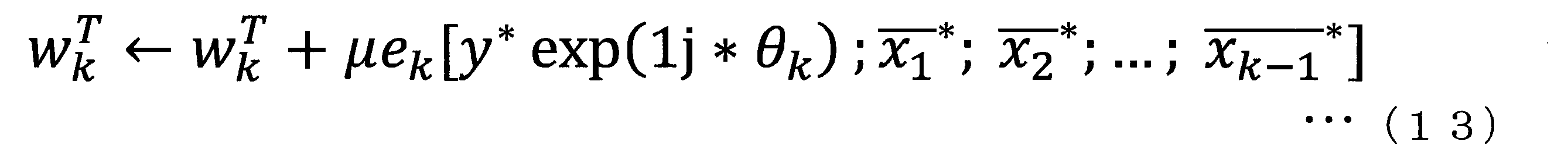
以上のように構成された光信号受信装置10bによれば、第1の実施形態及び第2の実施形態と同様の効果を得ることができる。
また、前述のように逐次干渉キャンセラの信号検出性能は、レプリカ信号の生成精度に大きく依存する。光コヒーレント検波の場合、受信信号には、送信側の光源と受信側の局発光の位相ずれや周波数ずれに起因する位相雑音が重畳する。従来の逐次干渉キャンセラを光通信に適用する場合、レプリカ信号の生成精度を高めるためには、空間フィルタリング部13b-kの入力前において、伝搬路での位相および振幅の変化、すなわちチャネル情報を高精度に求めることが要求されるだけではなく、位相雑音を高精度に求めることも要求される。それに対して、本実施形態における位相雑音推定部16-kと空間フィルタリング部13b-kとを組み合わせて用いることにより、チャネル情報の推定や位相雑音の推定を予め行うことが不要となる。 According to the opticalsignal receiving apparatus 10b configured as described above, the same effects as those of the first embodiment and the second embodiment can be obtained.
Further, as described above, the signal detection performance of the successive interference canceller largely depends on the generation accuracy of the replica signal. In the case of optical coherent detection, phase noise due to phase shift or frequency shift of the light source on the transmission side and the local light on the reception side is superimposed on the reception signal. When the conventional successive interference canceller is applied to optical communication, in order to improve the generation accuracy of the replica signal, the change in phase and amplitude in the propagation path, that is, the channel information is high before the input of thespatial filtering unit 13b-k. Not only the accuracy needs to be determined, but also the phase noise needs to be determined with high accuracy. On the other hand, by combining and using the phase noise estimation unit 16-k and the spatial filtering unit 13b-k in the present embodiment, it is not necessary to estimate channel information and estimate phase noise in advance.
また、前述のように逐次干渉キャンセラの信号検出性能は、レプリカ信号の生成精度に大きく依存する。光コヒーレント検波の場合、受信信号には、送信側の光源と受信側の局発光の位相ずれや周波数ずれに起因する位相雑音が重畳する。従来の逐次干渉キャンセラを光通信に適用する場合、レプリカ信号の生成精度を高めるためには、空間フィルタリング部13b-kの入力前において、伝搬路での位相および振幅の変化、すなわちチャネル情報を高精度に求めることが要求されるだけではなく、位相雑音を高精度に求めることも要求される。それに対して、本実施形態における位相雑音推定部16-kと空間フィルタリング部13b-kとを組み合わせて用いることにより、チャネル情報の推定や位相雑音の推定を予め行うことが不要となる。 According to the optical
Further, as described above, the signal detection performance of the successive interference canceller largely depends on the generation accuracy of the replica signal. In the case of optical coherent detection, phase noise due to phase shift or frequency shift of the light source on the transmission side and the local light on the reception side is superimposed on the reception signal. When the conventional successive interference canceller is applied to optical communication, in order to improve the generation accuracy of the replica signal, the change in phase and amplitude in the propagation path, that is, the channel information is high before the input of the
<変形例>
第k信号分離装置12b-kが備える仮判定信号出力部14-kは、誤り訂正の機能を有するものと置き換えてもよい。すなわち、仮判定信号出力部14-kが、第2の実施形態と同様に対数尤度比計算部、デインタリーバ、誤り訂正復号部、インタリーバ及びマッピング回路を備えてもよい。 <Modification>
The temporary determination signal output unit 14-k included in the kthsignal separation device 12b-k may be replaced with one having an error correction function. That is, as in the second embodiment, the temporary determination signal output unit 14-k may include a log likelihood ratio calculation unit, a deinterleaver, an error correction decoding unit, an interleaver, and a mapping circuit.
第k信号分離装置12b-kが備える仮判定信号出力部14-kは、誤り訂正の機能を有するものと置き換えてもよい。すなわち、仮判定信号出力部14-kが、第2の実施形態と同様に対数尤度比計算部、デインタリーバ、誤り訂正復号部、インタリーバ及びマッピング回路を備えてもよい。 <Modification>
The temporary determination signal output unit 14-k included in the kth
(第4の実施形態)
図7は、第4の実施形態における光信号受信装置10cにおける第k信号分離装置12c-kの機能構成を表す概略ブロック図である。なお、本実施形態においても説明の簡単化のためにSINRの高い順に受信信号yの成分をソートしたものとして説明を行う。
第k信号分離装置12c-kは、空間フィルタリング部13c-k、仮判定信号出力部14-k、重み係数更新部15c-k及び位相雑音推定部16-kを備える。 Fourth Embodiment
FIG. 7 is a schematic block diagram showing a functional configuration of the k-thsignal separation device 12c-k in the optical signal reception device 10c according to the fourth embodiment. Also in the present embodiment, in order to simplify the description, it is assumed that the components of the reception signal y are sorted in the descending order of SINR.
The k-thsignal separation device 12c-k includes a spatial filtering unit 13c-k, a temporary determination signal output unit 14-k, a weighting factor update unit 15c-k, and a phase noise estimation unit 16-k.
図7は、第4の実施形態における光信号受信装置10cにおける第k信号分離装置12c-kの機能構成を表す概略ブロック図である。なお、本実施形態においても説明の簡単化のためにSINRの高い順に受信信号yの成分をソートしたものとして説明を行う。
第k信号分離装置12c-kは、空間フィルタリング部13c-k、仮判定信号出力部14-k、重み係数更新部15c-k及び位相雑音推定部16-kを備える。 Fourth Embodiment
FIG. 7 is a schematic block diagram showing a functional configuration of the k-th
The k-th
第k信号分離装置12c-kは、空間フィルタリング部13b-k及び重み係数更新部15b-kに代えて空間フィルタリング部13c-k及び重み係数更新部15c-kを備える点で第k信号分離装置12b-k(例えば、k=2の場合、第二信号分離装置12b-2)と構成が異なる。第k信号分離装置12c-kにおける他の構成は第k信号分離装置12b-kと同様である。そのため、第k信号分離装置12c-kの全体の説明は省略し、空間フィルタリング部13c-k及び重み係数更新部15c-kについて説明する。
The k-th signal separation device 12c-k is different from the k-th signal separation device in that it includes a spatial filtering unit 13c-k and a weighting coefficient updating unit 15c-k instead of the spatial filtering unit 13b-k and the weighting coefficient updating unit 15b-k. The configuration is different from that of 12b-k (for example, in the case of k = 2, the second signal separation device 12b-2). The other configuration of the k-th signal separator 12c-k is similar to that of the k-th signal separator 12b-k. Therefore, the entire description of the k-th signal separation device 12c-k is omitted, and the spatial filtering unit 13c-k and the weight coefficient update unit 15c-k will be described.
空間フィルタリング部13c-kは、受信部11から出力されたNR個の信号と、第一信号分離装置12-1から第(k-1)信号分離装置12c-(k-1)までによって出力された第一仮判定信号x1
-から第(k-1)仮判定信号x(k-1)
-までとの合計(NR+k-1)個の信号を入力する。空間フィルタリング部13c-kは、入力した(NR+k-1)個の信号と、重み係数更新部15c-kから出力された第k重み係数wT
kと、位相雑音推定部16-kによって推定された位相雑音とを乗算することによって等化信号を分離する。例えば、空間フィルタリング部13c-kは、以下の式(14)に基づいて、等化信号xk^を分離する。
The spatial filtering unit 13c-k outputs the N R signals output from the receiving unit 11 and the first signal separation device 12-1 to the (k-1) th signal separation device 12c- (k-1). from the (k-1) temporary decision signal x (k-1) - - is first temporary decision signal x 1 and to a total of (N R + k-1) inputting a number of signals. The spatial filtering unit 13c-k receives the (N R + k-1) input signals, the k-th weighting coefficient w T k output from the weighting coefficient update unit 15c- k, and the phase noise estimation unit 16-k. Separate the equalized signal by multiplying it with the estimated phase noise. For example, the spatial filtering unit 13c-k separates the equalized signal x k ^ based on the following equation (14).
重み係数更新部15c-kは、空間フィルタリング部13c-kから出力された等化信号xk^を入力する。重み係数更新部15c-kは、LMS法やRLS法やCMA法などの適応アルゴリズムと、入力した等化信号xk^を用いて第k重み係数wT
kを更新する。例えば、LMS法を用いる場合、重み係数更新部15c-kは以下の式(15)のように第k重み係数wT
kを更新する。
The weighting factor update unit 15c-k receives the equalized signal x k ^ output from the spatial filtering unit 13c-k. The weighting factor updating unit 15c-k updates the kth weighting factor w T k using an adaptive algorithm such as LMS method, RLS method, CMA method, and the input equalized signal x k ^. For example, in the case of using the LMS method, the weight coefficient update unit 15c-k updates the kth weight coefficient w T k as shown in the following equation (15).
次に、空間フィルタリング部13c-kの詳細について説明する。空間フィルタリング部13c-kは、位相補正部134-k、係数乗算部135-k、乗算器136-k及び演算器137-kを備える。
演算器137-kは、位相雑音推定部16-kによって推定された位相雑音(図7におけるexp(-1j*θk)に相当)から位相雑音補正(図7におけるexp(1j*θk)に相当)を求める。位相補正部134-kは、入力した(NR+k-1)個の信号のうち(k-1)個の信号と、演算器137-kによって求められた位相雑音補正とを用いて、位相補正を行う。例えば、位相補正部134-kは、以下の式(16)に基づいて位相補正を行う。 Next, the details of thespatial filtering unit 13c-k will be described. The spatial filtering unit 13c-k includes a phase correction unit 134-k, a coefficient multiplication unit 135-k, a multiplier 136-k, and an operator 137-k.
Computing unit 137-k, the phase noise estimation unit 16-k by the estimated phase noise (corresponding to exp (-1j * θ k) in FIG. 7) from the phase noise correction (exp in FIG. 7 (1j * theta k) Equivalent to The phase correction unit 134-k uses the (k−1) signals of the input (N R + k−1) signals and the phase noise correction obtained by the computing unit 137-k to obtain a phase. Make corrections. For example, the phase correction unit 134-k performs phase correction based on the following equation (16).
演算器137-kは、位相雑音推定部16-kによって推定された位相雑音(図7におけるexp(-1j*θk)に相当)から位相雑音補正(図7におけるexp(1j*θk)に相当)を求める。位相補正部134-kは、入力した(NR+k-1)個の信号のうち(k-1)個の信号と、演算器137-kによって求められた位相雑音補正とを用いて、位相補正を行う。例えば、位相補正部134-kは、以下の式(16)に基づいて位相補正を行う。 Next, the details of the
Computing unit 137-k, the phase noise estimation unit 16-k by the estimated phase noise (corresponding to exp (-1j * θ k) in FIG. 7) from the phase noise correction (exp in FIG. 7 (1j * theta k) Equivalent to The phase correction unit 134-k uses the (k−1) signals of the input (N R + k−1) signals and the phase noise correction obtained by the computing unit 137-k to obtain a phase. Make corrections. For example, the phase correction unit 134-k performs phase correction based on the following equation (16).
式(16)において、pは整数であって、1≦p≦(k-1)である。例えば、図7の場合、位相補正部134-kは、第一信号分離装置12-1から出力された#NR+1の信号と、位相雑音補正とを乗算することによって、#NR+1の信号の位相補正を行う。また、位相補正部134-kは、第(k-1)信号分離装置12c-(k-1)から出力された#NR+(k-1)の信号と、位相雑音補正とを乗算することによって、#NR+(k-1)の信号の位相補正を行う。位相補正部134-kは、位相補正後の(k-1)個の信号を係数乗算部135-kに出力する。なお、位相補正部134-kに入力される(k-1)個の信号は、第一信号分離装置12c-1から第(k-1)信号分離装置12c-(k-1)までで出力された第一仮判定信号x1
-から第(k-1)仮判定信号x(k-1)
-である。
係数乗算部135-kは、入力した(NR+k-1)個の信号のうちNR個の信号と、位相補正後の(k-1)個の信号と、重み係数更新部15c-kから出力された第k重み係数wT kとを乗算する。
乗算器136-kは、係数乗算部135-kから出力された出力信号と、位相雑音推定部16-kによって推定された位相雑音とを乗算することによって等化信号xk^を生成する。乗算器136-kは、生成した等化信号xk^を仮判定信号出力部14-k、重み係数更新部15c-k及び位相雑音推定部16-kに出力する。 In the formula (16), p is an integer and 1 ≦ p ≦ (k−1). For example, in the case of FIG. 7, the phase correction unit 134-k multiplies the signal of #N R +1 output from the first signal separation device 12-1 by the phase noise correction to obtain #N R +1. Perform phase correction of the signal. Further, the phase correction unit 134-k multiplies the signal of #N R + (k-1) output from the (k-1) thsignal separation device 12c-(k-1) by the phase noise correction. Thus, phase correction of the signal of #N R + (k−1) is performed. The phase correction unit 134-k outputs (k−1) signals after phase correction to the coefficient multiplication unit 135-k. The (k-1) signals input to the phase correction unit 134-k are output from the first signal separation device 12c-1 to the (k-1) th signal separation device 12c- (k-1). The first temporary determination signal x 1 - to the (k-1) temporary determination signal x (k-1) - .
Coefficient multipliers 135-k are entered (N R + k-1) and the N R signals of the number of signals, after the phase correction (k-1) and the number of signals, the weightingfactor updating unit 15c-k And the k-th weighting factor w T k output from
The multiplier 136-k generates an equalized signal x k ^ by multiplying the output signal output from the coefficient multiplying unit 135-k and the phase noise estimated by the phase noise estimating unit 16-k. The multiplier 136-k outputs the generated equalized signal x k ^ to the temporary determination signal output unit 14-k, the weightcoefficient update unit 15c-k, and the phase noise estimation unit 16-k.
係数乗算部135-kは、入力した(NR+k-1)個の信号のうちNR個の信号と、位相補正後の(k-1)個の信号と、重み係数更新部15c-kから出力された第k重み係数wT kとを乗算する。
乗算器136-kは、係数乗算部135-kから出力された出力信号と、位相雑音推定部16-kによって推定された位相雑音とを乗算することによって等化信号xk^を生成する。乗算器136-kは、生成した等化信号xk^を仮判定信号出力部14-k、重み係数更新部15c-k及び位相雑音推定部16-kに出力する。 In the formula (16), p is an integer and 1 ≦ p ≦ (k−1). For example, in the case of FIG. 7, the phase correction unit 134-k multiplies the signal of #N R +1 output from the first signal separation device 12-1 by the phase noise correction to obtain #N R +1. Perform phase correction of the signal. Further, the phase correction unit 134-k multiplies the signal of #N R + (k-1) output from the (k-1) th
Coefficient multipliers 135-k are entered (N R + k-1) and the N R signals of the number of signals, after the phase correction (k-1) and the number of signals, the weighting
The multiplier 136-k generates an equalized signal x k ^ by multiplying the output signal output from the coefficient multiplying unit 135-k and the phase noise estimated by the phase noise estimating unit 16-k. The multiplier 136-k outputs the generated equalized signal x k ^ to the temporary determination signal output unit 14-k, the weight
以上のように構成された光信号受信装置10cによれば、第1の実施形態及び第2の実施形態と同様の効果を得ることができる。
According to the optical signal receiving device 10c configured as described above, the same effects as those of the first embodiment and the second embodiment can be obtained.
<変形例>
第k信号分離装置12c-kが備える仮判定信号出力部14-kは、誤り訂正の機能を有するものと置き換えてもよい。すなわち、仮判定信号出力部14-kが、第2の実施形態と同様に対数尤度比計算部、デインタリーバ、誤り訂正復号部、インタリーバ及びマッピング回路を備えてもよい。 <Modification>
The temporary determination signal output unit 14-k included in the kthsignal separation device 12c-k may be replaced with one having an error correction function. That is, as in the second embodiment, the temporary determination signal output unit 14-k may include a log likelihood ratio calculation unit, a deinterleaver, an error correction decoding unit, an interleaver, and a mapping circuit.
第k信号分離装置12c-kが備える仮判定信号出力部14-kは、誤り訂正の機能を有するものと置き換えてもよい。すなわち、仮判定信号出力部14-kが、第2の実施形態と同様に対数尤度比計算部、デインタリーバ、誤り訂正復号部、インタリーバ及びマッピング回路を備えてもよい。 <Modification>
The temporary determination signal output unit 14-k included in the kth
(第5の実施形態)
図8および図9は、第5の実施形態における光信号受信装置に設けられた信号分離装置の機能構成を表す概略ブロック図である。本実施形態の光信号受信装置は、図1に示した第一信号分離装置12-1および第k信号分離装置12-kに代えて、第一信号分離装置12d-1および第k信号分離装置12d-kを備える点で、第1の実施形態における光信号受信装置とは構成が異なっている。 Fifth Embodiment
8 and 9 are schematic block diagrams showing the functional configuration of a signal separation device provided in the optical signal reception device in the fifth embodiment. The optical signal receiving apparatus of this embodiment is different from the first signal demultiplexing apparatus 12-1 and the k-th signal demultiplexing apparatus 12-k shown in FIG. 1 in the firstsignal demultiplexing apparatus 12d-1 and the k-th signal demultiplexing apparatus The configuration is different from that of the optical signal receiving apparatus according to the first embodiment in that 12d-k is provided.
図8および図9は、第5の実施形態における光信号受信装置に設けられた信号分離装置の機能構成を表す概略ブロック図である。本実施形態の光信号受信装置は、図1に示した第一信号分離装置12-1および第k信号分離装置12-kに代えて、第一信号分離装置12d-1および第k信号分離装置12d-kを備える点で、第1の実施形態における光信号受信装置とは構成が異なっている。 Fifth Embodiment
8 and 9 are schematic block diagrams showing the functional configuration of a signal separation device provided in the optical signal reception device in the fifth embodiment. The optical signal receiving apparatus of this embodiment is different from the first signal demultiplexing apparatus 12-1 and the k-th signal demultiplexing apparatus 12-k shown in FIG. 1 in the first
図8は第一信号分離装置12d-1の機能構成を表す概略ブロック図であり、図9は第k信号分離装置12d-kの機能構成を表す概略ブロック図である。第一信号分離装置12d-1は、空間フィルタリング部13d-1と仮判定信号出力部14d-1-1~14d-1-NTを備える。第k信号分離装置12d-kは、空間フィルタリング部13d-kと仮判定信号出力部14d-k-1~14d-k-NTを備える。空間フィルタリング部13d-1および空間フィルタリング部13d-kは、それぞれ、NT個の空間フィルタリング部によって構成される。
FIG. 8 is a schematic block diagram showing the functional configuration of the first signal separation device 12d-1, and FIG. 9 is a schematic block diagram showing the functional configuration of the k-th signal separation device 12d-k. First signal separator 12d-1 includes a spatial filtering unit 13d-1 temporary decision signal output unit 14d-1-1 ~ 14d-1- N T. The k signal separator 12d-k includes a spatial filtering unit 13d-k and the temporary judgment signal output unit 14d-k-1 ~ 14d- k-N T. Each of the spatial filtering unit 13d-1 and the spatial filtering unit 13d-k includes N T spatial filtering units.
次に、第一信号分離装置12d-1および第k信号分離装置12d-kの処理を説明する。受信信号系列y1~yNR(“1”および“NR”は下付き添え字)は、第一信号分離装置12d-1の空間フィルタリング部13d-1に入力される。空間フィルタリング部13d-1は、受信信号系列y1~yNRに重み係数を乗算し、等化出力系列x1^(1)~xNT^(1)(等化信号)(“1”および“NT”は下付き添え字)を出力する。ここで、括弧内の数字(この場合は、“1”)は信号分離装置の番号を表す。仮判定信号出力部14d-1-1~14d-1-NTは、それぞれ、等化出力系列x1^(1)~xNT^(1)を入力し、入力した信号を仮判定し、判定結果を仮判定信号系列x1~(1)~xNT
~(1)(~は“x1”および“xNT”の上に付される)として出力する。ここで、仮判定とは、等化信号として尤もらしい信号を判定することを意味する。なお、判定の処理の一例は第1の実施形態で説明した通りである。
Next, processing of the first signal separation device 12d-1 and the k-th signal separation device 12d-k will be described. Received signal sequence y1 ~ yN R ( "1" and "N R" is subscript) is input to the spatial filtering unit 13d-1 of the first signal separator 12d-1. The spatial filtering unit 13d-1 multiplies the received signal sequence y1 to yN R by a weighting factor to obtain an equalized output sequence x1 ^ (1) to x N T ^ (1) (equalized signal) ("1" and "N"). " T " outputs a subscript. Here, the number in parentheses (in this case, "1") represents the number of the signal separation device. The temporary determination signal output units 14d-1-1 to 14d-1-N T receive equalized output sequences x1 ^ (1) to xN T ^ (1), respectively, and temporarily determine the input signals to make a determination. It outputs the result as a temporary judgment signal sequence x1 ~ (1) ~ xN T ~ (1) (~ are subjected on the "x1" and "xN T"). Here, temporary determination means determining a signal that is likely to be an equalized signal. Note that an example of the determination process is as described in the first embodiment.
次に、受信信号系列y1~yNRと、仮判定信号系列x1~(1)~xNT
~(1)は、図9に示す第二信号分離装置12d-2(この場合、図9におけるk=2)の空間フィルタリング部13d-2に入力される。空間フィルタリング部13d-2は、受信信号系列y1~yNRおよび仮判定信号系列x1~(1)~xNT
~(1)に重み係数を乗算し、等化出力系列x1^(2)~xNT^(2)を出力する。仮判定信号出力部14d-2-1~14d-2-NTは、等化出力系列x1^(2)~xNT^(2)を入力とし、入力した信号を仮判定し、判定結果をそれぞれ仮判定信号系列x1~(2)~xNT
~(2)として出力する。第三信号分離装置12d-3(図9におけるk=3)以降の信号検出処理は、第二信号分離装置12d-2と同様に行われる。
Then, a received signal sequence y1 ~ yN R, temporary decision signal sequence x1 ~ (1) ~ xN T ~ (1) , the second signal separator 12d-2 illustrated in FIG. 9 (in this case, k in FIG. 9 2) is input to the spatial filtering unit 13d-2. Spatial filtering unit 13d-2 multiplies the weighting factor ~ received signal sequence y1 ~ yN R and the temporary decision signal sequence x1 (1) ~ xN T ~ (1), the equalization output sequence x1 ^ (2) ~ xN Output T ^ (2). The temporary determination signal output units 14d-2-1 to 14d-2-N T receive the equalized output series x1 ^ (2) to xN T ^ (2), temporarily determine the input signal, and determine the determination result. The temporary determination signal sequences x1 to (2) to xN T to (2) are output. The signal detection processing after the third signal separation device 12d-3 (k = 3 in FIG. 9) is performed in the same manner as the second signal separation device 12d-2.
上記のように、第一信号分離装置12d-1および第k信号分離装置12d-kを用いて、信号検出処理を複数ステージで行うことにより、信号検出精度を高めながら、受信信号に重畳した干渉成分を効果的に取り除くことができる。このとき、kは信号検出処理の繰り返し回数に相当し、事業者が設定できる数となる。本実施形態では、kの上限値をP(「所定回数」)と置く。繰り返し処理を行う装置は多くがフィードバック構造を備えるが、本実施形態では、複数個の信号分離装置を(縦続)接続することにより、等価的に繰り返し処理を行うことができる。
As described above, by performing signal detection processing in a plurality of stages using the first signal separation device 12d-1 and the k-th signal separation device 12d-k, interference superimposed on the reception signal while improving signal detection accuracy. The ingredients can be removed effectively. At this time, k corresponds to the number of repetitions of the signal detection process, and is a number that can be set by the business operator. In the present embodiment, the upper limit value of k is set to P (“predetermined number of times”). Although many devices that perform repetitive processing have a feedback structure, in the present embodiment, it is possible to equivalently repeat processing by connecting a plurality of signal separation devices (in cascade).
上記の処理がPステージ(すなわち、第P信号分離装置12d-P)まで行われ、最終的に、信号系列x1~~xNT
~が出力される。
The above processing is P stages (i.e., the P signal separator 12d-P) performed until, finally, the signal sequence x1 ~ ~ xN T ~ is output.
図10は、空間フィルタリング部13d-kを構成する第(k-i)空間フィルタリング部13d-k-iの機能構成の一例を表す概略ブロック図である(iは1以上NT以下の整数)。第(k-i)空間フィルタリング部13d-k-iは、i番目の信号検出処理を行う。第(k-i)空間フィルタリング部13d-k-iは、第一乗算部131d-kと、乗算器131da-k(第三乗算部)と、第二乗算部132d-kと、加算器133d-k(加算部)と、重み係数更新部15d-kと、位相雑音推定部16d-kを備える。図9に示す第k信号分離装置12d-k内における空間フィルタリング部13d-kは、第(k-i)空間フィルタリング部がNT個組み合わされて構成される。
FIG. 10 is a schematic block diagram showing an example of a functional configuration of a (k-i) spatial filtering unit 13d-k-i constituting the spatial filtering unit 13d-k (i is an integer of 1 or more and NT or less) . The (ki) spatial filtering unit 13d-ki performs an i-th signal detection process. The (ki) spatial filtering unit 13d-k-i includes a first multiplication unit 131d-k, a multiplier 131da-k (third multiplication unit), a second multiplication unit 132d-k, and an adder 133d. -K (addition unit), weight coefficient update unit 15d-k, and phase noise estimation unit 16d-k. The spatial filtering unit 13d-k in the k-th signal separation device 12d-k shown in FIG. 9 is configured by combining NT (k-i) spatial filtering units.
次に、図10に示す第(k-i)空間フィルタリング部13d-k-iの信号検出処理について説明する。第一乗算部131d-kは、受信信号系列y1~yNRに対して重み係数更新部15d-kから出力される重み係数を乗算し、乗算結果を出力する。第二乗算部132d-kは、仮判定信号系列x1~(k-1)~xNT
~(k-1)に対して重み係数更新部15d-kから出力される重み係数を乗算し、乗算結果を出力する。乗算器131da-kは、第一乗算部131d-kから出力される乗算結果と、位相雑音推定部16d-kから出力される位相雑音に相当するexp(-1j*θ)の項を乗算する。加算器133d-kは、乗算器131da-kから出力される乗算結果と、第二乗算部132d-kから出力される乗算結果を足し合わせて、等化出力系列xi^(k)を出力する。
Next, the signal detection process of the (ki) spatial filtering unit 13d-ki shown in FIG. 10 will be described. The first multiplication unit 131 d-k multiplies the received signal sequence y 1 to y N R by the weighting coefficient output from the weighting coefficient update unit 15 d-k, and outputs the multiplication result. The second multiplying unit 132d-k, multiplies the temporary decision signal sequence x1 ~ (k-1) ~ xN T ~ (k-1) weighting factor output from the weighting factor updating unit 15d-k with respect to the multiplication Output the result. The multiplier 131da-k multiplies the multiplication result output from the first multiplier 131d-k by the term exp (-1j * θ) corresponding to the phase noise output from the phase noise estimator 16d-k. . The adder 133d-k adds the multiplication result output from the multiplier 131da-k and the multiplication result output from the second multiplication unit 132d-k, and outputs an equalized output sequence xi ^ (k). .
位相雑音推定部16d-kと重み係数更新部15d-kは、等化出力系列xi^(k)に基づいて教師データを作成し、所定のアルゴリズムに則り、それぞれ、位相雑音の推定と重み係数の更新を行う。所定のアルゴリズムとして、位相雑音推定部16d-kでは例えばビタビ・ビタビ法が用いられ、重み係数更新部15d-kでは例えば確率勾配法が用いられる。
The phase noise estimation unit 16d-k and the weight coefficient update unit 15d-k create training data based on the equalized output sequence xi ^ (k), and estimate phase noise and weight coefficients according to a predetermined algorithm. Update the As a predetermined algorithm, for example, the Viterbi-Viterbi method is used in the phase noise estimation unit 16d-k, and the probability gradient method is used in the weight coefficient update unit 15d-k.
図11は、空間フィルタリング部13d-kを構成する第(k-i)空間フィルタリング部13d-k-iの機能構成の他の例を表す概略ブロック図である。図11に示す第(k-i)空間フィルタリング部は、第一乗算部131d-kと、乗算器131da-kと、第二乗算部132d-kと、加算器133d-kを備えず、位相補正部134d-kと係数乗算部135d-kと乗算器136d-kと演算器137d-kを備える点で、図10に示す第(k-i)空間フィルタリング部と構成が異なっている。
FIG. 11 is a schematic block diagram showing another example of the functional configuration of the (ki) spatial filtering unit 13d-k-i configuring the spatial filtering unit 13d-k. The (k−) spatial filtering unit illustrated in FIG. 11 does not include the first multiplication unit 131 d-k, the multiplier 131 da-k, the second multiplication unit 132 d-k, and the adder 133 d-k, The configuration is different from the (ki) spatial filtering unit shown in FIG. 10 in that the correction unit 134d-k, the coefficient multiplying unit 135d-k, the multiplier 136d-k, and the computing unit 137d-k are provided.
次に、図11に示す第(k-i)空間フィルタリング部13d-k-iの信号検出処理について説明する。演算器137d-kは、位相雑音推定部16d-kによって推定された位相雑音(図11におけるexp(-1j*θ)に相当)から位相雑音補正(図11におけるexp(1j*θ)に相当)を求める。位相補正部134d-kは、仮判定信号系列x1~(k-1)~xNT
~(k-1)に対して、それぞれ位相雑音補正に相当するexp(1j*θ)の項を乗算することで、仮判定信号系列x1~(k-1)~xNT
~(k-1)に対して実効的に位相雑音を付加して、位相補正を行う。係数乗算部135d-kは、位相雑音補正後の仮判定信号系列および受信信号系列y1~yNRに対して、重み係数更新部15d-kから出力される重み係数を乗算し、乗算結果を出力する。乗算器136d-kは、係数乗算部135d-kから出力される乗算結果と、位相雑音推定部16d-kによって推定された位相雑音に相当するexp(-1j*θ)の項、とを乗算し、等化出力系列xi^(k)を出力する。
重み係数更新部15d-kと位相雑音推定部16d-kは、図10に示す同名の機能部と同じ処理を行うため、ここではそれらの説明を省略する。 Next, the signal detection process of the (ki)spatial filtering unit 13d-ki shown in FIG. 11 will be described. Arithmetic units 137 d-k correspond to phase noise correction (exp (1 j * θ) in FIG. 11) from phase noise (corresponding to exp (−1 j * θ) in FIG. 11) estimated by phase noise estimation unit 16 d-k Ask for). The phase correction unit 134d-k multiplies the temporary determination signal sequence x1 to (k-1) to xN T to (k-1) by the term of exp (1j * θ) corresponding to the phase noise correction. it is, by adding an effective manner the phase noise relative to the temporary decision signal sequence x1 ~ (k-1) ~ xN T ~ (k-1), performs a phase correction. Coefficient multiplying unit 135d-k, to the temporary decision signal sequence and the received signal sequence y1 ~ yN R after the phase noise correction, multiplied by the weighting factor output from the weighting factor updating unit 15d-k, outputs a multiplication result Do. The multiplier 136d-k multiplies the multiplication result output from the coefficient multiplying unit 135d-k by the term of exp (-1j * θ) corresponding to the phase noise estimated by the phase noise estimating unit 16d-k. And output an equalized output sequence xi ^ (k).
The weightingfactor updating unit 15d-k and the phase noise estimating unit 16d-k perform the same processing as the functional units of the same name illustrated in FIG. 10, and thus the description thereof is omitted here.
重み係数更新部15d-kと位相雑音推定部16d-kは、図10に示す同名の機能部と同じ処理を行うため、ここではそれらの説明を省略する。 Next, the signal detection process of the (ki)
The weighting
<変形例>
仮判定信号出力部14d-1-1~14d-1-NTおよび仮判定信号出力部14d-k-1~14d-k-NTは、誤り訂正の機能を有するものと置き換えてもよい。すなわち、これら仮判定信号出力部のそれぞれが、第2の実施形態と同様に、対数尤度比計算部、デインタリーバ、誤り訂正復号部、インタリーバ及びマッピング回路を備えてもよい。 <Modification>
The temporary determinationsignal output units 14d-1-1 to 14d-1-N T and the temporary determination signal output units 14d-k-1 to 14d-k-N T may be replaced with those having an error correction function. That is, each of these temporary determination signal output units may be provided with a log likelihood ratio calculation unit, a deinterleaver, an error correction decoding unit, an interleaver, and a mapping circuit as in the second embodiment.
仮判定信号出力部14d-1-1~14d-1-NTおよび仮判定信号出力部14d-k-1~14d-k-NTは、誤り訂正の機能を有するものと置き換えてもよい。すなわち、これら仮判定信号出力部のそれぞれが、第2の実施形態と同様に、対数尤度比計算部、デインタリーバ、誤り訂正復号部、インタリーバ及びマッピング回路を備えてもよい。 <Modification>
The temporary determination
(第6の実施形態)
図12および図13は、第6の実施形態における光信号受信装置に設けられた信号分離装置の機能構成を表す概略ブロック図である。図12は第一信号分離装置12e-1の機能構成を表す概略ブロック図であり、図13は第k信号分離装置12e-kの機能構成を表す概略ブロック図である。これらの信号分離装置は、第5の実施形態における第一信号分離装置12d-1および第k信号分離装置12d-k内の仮判定信号出力部14d-1-1~14d-1-NTおよび仮判定信号出力部14d-k-1~14d-k-NTの代わりに、軟判定信号出力部14e-1-1~14e-1-NTおよび軟判定信号出力部14e-k-1~14e-k-NTを備える点で、第5の実施形態における信号分離装置と構成が異なっている。 Sixth Embodiment
12 and 13 are schematic block diagrams showing the functional configuration of a signal separation device provided in the optical signal reception device in the sixth embodiment. FIG. 12 is a schematic block diagram showing the functional configuration of the firstsignal separation device 12e-1, and FIG. 13 is a schematic block diagram showing the functional configuration of the k-th signal separation device 12e-k. These signal separation devices are the temporary determination signal output units 14d-1-1 to 14d-1-N T in the first signal separation device 12d-1 and the k-th signal separation device 12d-k in the fifth embodiment, and The soft decision signal output units 14e-1-1 to 14e-1-N T and the soft decision signal output units 14e-k-1 to 15e instead of the temporary decision signal output units 14d-k-1 to 14d-k-N T The configuration is different from that of the signal separation apparatus according to the fifth embodiment in that 14e-k-N T is provided.
図12および図13は、第6の実施形態における光信号受信装置に設けられた信号分離装置の機能構成を表す概略ブロック図である。図12は第一信号分離装置12e-1の機能構成を表す概略ブロック図であり、図13は第k信号分離装置12e-kの機能構成を表す概略ブロック図である。これらの信号分離装置は、第5の実施形態における第一信号分離装置12d-1および第k信号分離装置12d-k内の仮判定信号出力部14d-1-1~14d-1-NTおよび仮判定信号出力部14d-k-1~14d-k-NTの代わりに、軟判定信号出力部14e-1-1~14e-1-NTおよび軟判定信号出力部14e-k-1~14e-k-NTを備える点で、第5の実施形態における信号分離装置と構成が異なっている。 Sixth Embodiment
12 and 13 are schematic block diagrams showing the functional configuration of a signal separation device provided in the optical signal reception device in the sixth embodiment. FIG. 12 is a schematic block diagram showing the functional configuration of the first
軟判定信号出力部14e-1-1~14e-1-NTおよび軟判定信号出力部14e-k-1~14e-k-NTは、それぞれ、空間フィルタリング部13d-1および空間フィルタリング部13d-kから出力された等化出力系列x1^(1)~xNT^(1)および等化出力系列x1^(k)~xNT^(k)を入力とする。そして、軟判定信号出力部14e-1-1~14e-1-NTおよび14e-k-1~14e-k-NTは、入力された等化出力系列に予め付加された誤り訂正符号のパリティなどを利用して、送信ビットや送信シンボルなどの送信信号情報の尤度情報を算出し、尤度情報に基づく軟判定シンボルを生成し、生成された軟判定シンボルをそれぞれ等化出力系列x1^(1)~xNT^(1)および等化出力系列x1^(k)~xNT^(k)として出力する。その他の信号の入出力の関係および各機能部の処理は第5の実施形態と同様であるので、ここではそれらの説明を省略する。
Soft decision signal output units 14e-1-1 to 14e-1-N T and soft decision signal output units 14e-k-1 to 14e-k-N T are respectively spatial filtering unit 13d-1 and spatial filtering unit 13d. The equalized output series x1 ^ (1) to xN T ^ (1) and equalized output series x1 ^ (k) to xN T ^ (k) output from -k are input. The soft decision signal output units 14e-1-1 to 14e-1-N T and 14e-k-1 to 14e-k-N T are error correction codes added in advance to the input equalized output sequence. The likelihood information of transmission signal information such as transmission bits and transmission symbols is calculated using parity etc., soft decision symbols are generated based on likelihood information, and the generated soft decision symbols are respectively equalized output sequence x 1 Output as ^ (1) to xN T ^ (1) and equalized output series x1 ^ (k) to xN T ^ (k). The other signal input / output relationships and the processing of each functional unit are the same as in the fifth embodiment, and thus the description thereof is omitted here.
図14は、本実施形態における各軟判定信号出力部の機能構成を表す概略ブロック図である。各軟判定信号出力部は、対数尤度比計算部141eと、デインタリーバ142eと、誤り訂正復号部143eと、インタリーバ144eと、軟判定シンボル生成部146eと、減算器147eを備える。
FIG. 14 is a schematic block diagram showing a functional configuration of each soft decision signal output unit in the present embodiment. Each soft decision signal output unit includes a log likelihood ratio calculator 141 e, a deinterleaver 142 e, an error correction decoder 143 e, an interleaver 144 e, a soft decision symbol generator 146 e, and a subtractor 147 e.
対数尤度比計算部141eは、空間フィルタリング部13d-1または空間フィルタリング部13d-kから出力された等化出力系列xi^(k)を入力とし、等化出力系列を構成する各ビットについて、0が送信された確率と1が送信された確率との対数尤度比La(bi
t)を算出する。ここで、bi
tは、i番目の送信信号系列のt番目のビットを表す。対数尤度比計算部141eは、算出した対数尤度比La(bi
t)をデインタリーバ142eに出力する。デインタリーバ142eは、入力された対数尤度比La(bi
t)をビット毎に並び替え、La(ci
t)を出力する。ここで、ci
tはbi
tを並び替えたバイナリ系列である。デインタリーバ142eは、並び替え後の対数尤度比La(ci
t)を誤り訂正復号部143eおよび減算器147eに出力する。
The log likelihood ratio calculation unit 141 e receives the equalized output sequence xi ^ (k) output from the spatial filtering unit 13 d-1 or the spatial filtering unit 13 d-k and inputs each of the bits constituting the equalized output sequence 0 calculates the log likelihood ratio L a (b i t) between the transmission probabilities and the probability of 1 is transmitted. Here, b i t represents the t-th bit of the i-th transmission signal sequence. The log likelihood ratio calculation unit 141 e outputs the calculated log likelihood ratio L a (b i t ) to the deinterleaver 142 e . The deinterleaver 142 e rearranges the input log likelihood ratio L a (b i t ) bit by bit, and outputs L a (c i t ). Here, c i t is a binary sequence in which b i t is rearranged. The deinterleaver 142 e outputs the rearranged log likelihood ratio L a (c i t ) to the error correction decoding unit 143 e and the subtractor 147 e.
誤り訂正復号部143eは、光信号送信装置側で用いられた誤り訂正符号と同様の誤り訂正符号に基づき、適切な復号方法を用いて、各ビットについて事後対数尤度比Lp(ci
t)を算出する。ここで、ci
tは、i番目の送信信号系列のt番目のビットを表す。本実施形態における誤り訂正符号とは、例えばハミング符号、BCH符号、LDPC符号及び畳み込み符号等の特定の誤り訂正符号に限定されることなく、あらゆる訂正符号が用いられても良い。
Error correction decoding section 143e, based on the same error correction code and the error correction code used in optical signal transmission apparatus, using an appropriate decoding method, for each bit a posteriori log likelihood ratio L p (c i t Calculate). Here, c i t represents the t-th bit of the i-th transmission signal sequence. The error correction code in the present embodiment is not limited to a specific error correction code such as a Hamming code, a BCH code, an LDPC code, and a convolutional code, and any correction code may be used.
次に、減算器147eは、誤り訂正復号部143eから出力される事後対数尤度比Lp(ci
t)から誤り訂正復号部143eへの入力でもあるLa(ci
t)を減算することによって、次式に示すように、外部対数尤度比Le(ci
t)を算出する。
Le(ci t)=Lp(ci t)-La(ci t) …(17) Next, the subtractor 147 e subtracts L a (c i t ) that is also an input to the errorcorrection decoding unit 143 e from the posterior log likelihood ratio L p (c i t ) output from the error correction decoding unit 143 e. Thus, the external log likelihood ratio L e (c i t ) is calculated as shown in the following equation.
L e (c i t ) = L p (c i t ) -L a (c i t ) (17)
Le(ci t)=Lp(ci t)-La(ci t) …(17) Next, the subtractor 147 e subtracts L a (c i t ) that is also an input to the error
L e (c i t ) = L p (c i t ) -L a (c i t ) (17)
減算器147eは、外部対数尤度比Le(ci
t)をインタリーバ144eへ出力する。インタリーバ144eは、外部対数尤度比Le(ci
t)を並び替えてLe(bi
t)を出力する。
The subtractor 147 e outputs the outer log likelihood ratio L e (c i t ) to the interleaver 144 e . Interleaver 144e outputs the external log likelihood ratio L e (c i t) rearranges the place and L e (b i t).
Le(bi
t)は軟判定シンボル生成部146eへ入力される。軟判定シンボル生成部146eは、入力されたLe(bi
t)から軟判定シンボル系列bi
t
~を生成する。軟判定シンボル生成部146eでは、例えば送信信号系列がBPSK(Binary Phase Shift Keying)変調されているとき、次式に従って、軟判定シンボル系列を生成する。
bi t ~=tanh(bi t) …(18) L e (b i t ) is input to the soft decision symbol generator 146 e . Softdecision symbol generator 146e generates the soft decision symbol sequence b i t ~ from the input L e (b i t). For example, when the transmission signal sequence is BPSK (Binary Phase Shift Keying) modulation, the soft decision symbol generation unit 146 e generates a soft decision symbol sequence according to the following equation.
b i t ~ = tanh (b i t) ... (18)
bi t ~=tanh(bi t) …(18) L e (b i t ) is input to the soft decision symbol generator 146 e . Soft
b i t ~ = tanh (b i t) ... (18)
(第7の実施形態)
図15は、第7の実施形態における光信号受信装置に設けられた信号分離装置の機能構成を表す概略ブロック図である。本実施形態の信号分離装置12fは、空間フィルタリング部13f及び判定信号出力部14f-1~14f-NTを備える。空間フィルタリング部13fは、第5実施形態で説明した空間フィルタリング部または第6実施形態で説明した空間フィルタリングと同様の機能を有する。判定信号出力部14f-1~14f-NTは、上述した実施形態における仮判定信号出力部または軟判定信号出力部である。 Seventh Embodiment
FIG. 15 is a schematic block diagram showing a functional configuration of a signal separation device provided in the optical signal receiving device in the seventh embodiment. Signal separatingapparatus 12f of this embodiment includes a spatial filtering section 13f and the determination signal output unit 14f-1 ~ 14f-N T . The spatial filtering unit 13 f has the same function as the spatial filtering unit described in the fifth embodiment or the spatial filtering described in the sixth embodiment. The determination signal output units 14f-1 to 14f- NT are the temporary determination signal output units or the soft determination signal output units in the above-described embodiment.
図15は、第7の実施形態における光信号受信装置に設けられた信号分離装置の機能構成を表す概略ブロック図である。本実施形態の信号分離装置12fは、空間フィルタリング部13f及び判定信号出力部14f-1~14f-NTを備える。空間フィルタリング部13fは、第5実施形態で説明した空間フィルタリング部または第6実施形態で説明した空間フィルタリングと同様の機能を有する。判定信号出力部14f-1~14f-NTは、上述した実施形態における仮判定信号出力部または軟判定信号出力部である。 Seventh Embodiment
FIG. 15 is a schematic block diagram showing a functional configuration of a signal separation device provided in the optical signal receiving device in the seventh embodiment. Signal separating
本実施形態の信号分離装置12fは、繰り返し処理を基本とし、フィードバック構造を備える。
The signal separation device 12f of the present embodiment is based on repetitive processing and has a feedback structure.
次に、本実施形態の信号分離装置12fにおける信号検出処理について説明する。まず、信号検出処理を繰り返し行う回数の上限値Pを設定する。次に、一回目の信号検出処理では、受信信号系列y1~yNRが空間フィルタリング部13fに入力される。この場合、空間フィルタリング部13fは、判定信号出力部14f-1~14f-NTからフィードバックされた信号は使用しない。空間フィルタリング部13fは、受信信号系列y1~yNRに重み係数を乗算し、等化出力系列x1^(1)~xNT^(1)を出力する。ここで、括弧内の数字は繰り返しの回数を表す(この場合は、一回目の信号検出処理であるため、“1”)。次に、判定信号出力部14f-1~14f-NTは、それぞれ、等化出力系列x1^(1)~xNT^(1)を入力とし、入力された等化出力系列に対して判定(すなわち、上述した仮判定信号出力部または軟判定信号出力部による判定)を行い、得られた仮判定信号系列または軟判定信号系列を判定信号系列x1~(1)~xNT
~(1)として空間フィルタリング部13fに出力する。
Next, signal detection processing in the signal separation device 12 f of this embodiment will be described. First, the upper limit value P of the number of times the signal detection process is repeated is set. Then, the signal detection processing one time is received sequence y1 ~ yN R is input to the spatial filtering section 13f. In this case, the spatial filtering unit 13f does not use the signals fed back from the determination signal output units 14f-1 to 14f- NT . Spatial filtering unit 13f multiplies the weight coefficient in the reception signal sequence y1 ~ yN R, and outputs an equalized output sequence x1 ^ (1) ~ xN T ^ (1). Here, the numbers in parentheses indicate the number of repetitions (in this case, “1” because this is the first signal detection processing). Next, determination signal output units 14f-1 to 14f-N T receive equalized output sequences x1 ^ (1) to xN T ^ (1), respectively, and perform determination on the input equalized output sequence (i.e., determination by the provisional determination signal output unit or the soft decision signal outputting unit described above) is performed, resulting temporary decision signal sequence or soft decision signal sequence determination signal sequence x1 ~ (1) ~ xN T ~ (1) Output to the spatial filtering unit 13f.
以降のk回目の信号検出処理では、受信信号系列y1~yNRおよび判定信号出力部14f-1~14f-NTからフィードバックされた判定信号系列x1~(k-1)~xNT
~(k-1)が、空間フィルタリング部13fに入力される。例えば、2回目の信号検出処理(k=2)では、受信信号系列y1~yNRおよび判定信号出力部14f-1~14f-NTからフィードバックされた判定信号系列x1~(1)~xNT
~(1)が、空間フィルタリング部13fに入力される。空間フィルタリング部13fは、受信信号系列y1~yNRおよび判定信号系列x1~(k-1)~xNT
~(k-1)に対して重み係数を乗算し、等化出力系列x1^(k)~xNT^(k)を出力する。判定信号出力部14f-1~14f-NTは、それぞれ、等化出力系列x1^(k)~xNT^(k)を入力とし、入力された等化出力系列に対して判定を行い、得られた仮判定信号系列または軟判定信号系列を空間フィルタリング部13fにフィードバックする。
上記の信号検出処理がk=Pに対して行われるまで繰り返されると、信号分離装置12fは、判定信号系列x1~~xNT ~を出力する。 In the subsequent k-th signal detection processing, the determination signal sequences x1 to (k-1) to xN T (k to (k) are fed back from the reception signal sequences y1 to yN R and the determinationsignal output units 14f-1 to 14f-N T -1) is input to the spatial filtering unit 13f. For example, the second signal detection process (k = 2), the received signal sequence y1 ~ yN R and determination signal outputting unit 14f-1 ~ 14f-N T fed back from the determination signal sequence x1 ~ (1) ~ xN T ~ (1) is input to the spatial filtering section 13f. The spatial filtering unit 13 f multiplies the received signal sequence y 1 to y N R and the determination signal sequence x 1 to (k−1) to xN T to (k−1) by a weighting factor to obtain an equalized output sequence x 1 ^ (k ) To xN T ^ (k). Determination signal output units 14f-1 to 14f-N T receive equalized output sequences x1 ^ (k) to xN T ^ (k), respectively, and perform determination on the input equalized output sequences, The obtained temporary determination signal sequence or soft determination signal sequence is fed back to the spatial filtering unit 13 f.
When repeated until the above signal detection process is performed on k = P, thesignal separation device 12f is determined signal sequence x1 ~ ~ xN T outputs ~ a.
上記の信号検出処理がk=Pに対して行われるまで繰り返されると、信号分離装置12fは、判定信号系列x1~~xNT ~を出力する。 In the subsequent k-th signal detection processing, the determination signal sequences x1 to (k-1) to xN T (k to (k) are fed back from the reception signal sequences y1 to yN R and the determination
When repeated until the above signal detection process is performed on k = P, the
第7の実施形態の効果を確認するための伝送シミュレーションを行った結果を図16に示す。図16では、伝送路モデルとして、2×2のMIMOシステムを想定した。2つの光信号送信装置から独立したQPSK信号を送信し、信号対雑音比(SNR)を変化させたときの両信号の平均ビットエラーレートを記録した。図16には、従来方式と第7の実施形態のビットエラーレートの比較結果が示されている。図16からは、第7の実施形態を適用することによって、ビットエラーレート10-2においてSNRの利得(すなわち、SNR利得)として約1.5dBが得られていることが分かる。
The result of transmission simulation for confirming the effect of the seventh embodiment is shown in FIG. In FIG. 16, a 2 × 2 MIMO system is assumed as a transmission path model. Independent QPSK signals were transmitted from the two optical signal transmitters, and the average bit error rate of both signals when the signal-to-noise ratio (SNR) was changed was recorded. FIG. 16 shows the comparison results of bit error rates of the conventional method and the seventh embodiment. It can be seen from FIG. 16 that by applying the seventh embodiment, about 1.5 dB is obtained as the SNR gain (that is, the SNR gain) at a bit error rate of 10 −2 .
上記の各実施形態では、光信号受信装置が主に時間領域の処理を行うものとして記述したが、各実施形態の光信号受信装置における時間領域の処理を周波数領域の処理に置き換えてもよい。
In each of the above embodiments, the optical signal receiving apparatus has been described as performing mainly the processing in the time domain, but the processing in the time domain in the optical signal receiving apparatus of each embodiment may be replaced with the processing in the frequency domain.
上記の各実施形態における光信号受信装置を無線通信システム、衛星通信システム等の光通信システム以外の通信システム上で実現してもよい。また、上述したシングルキャリア通信システムに限定することなく、OFDM(Orthogonal Frequency Division Multiplexing)等のマルチキャリア通信システム、CDMA(Code Division Multiplexing Access)等の符号化拡散通信システムに対しても上記の各実施形態は同様に実施できる。
The optical signal receiving apparatus in each of the above embodiments may be realized on a communication system other than an optical communication system such as a wireless communication system or a satellite communication system. Further, the present invention is not limited to the single carrier communication system described above, and the above embodiments may be applied to multicarrier communication systems such as orthogonal frequency division multiplexing (OFDM) and coded spread communication systems such as code division multiplexing access (CDMA). The form can be implemented as well.
また別の例として、上述した光信号受信装置をコンピュータで実現してもよい。その場合、これら装置の機能を実現するためのプログラムをコンピュータ読み取り可能な記録媒体に記録し、この記録媒体に記録されたプログラムをコンピュータシステムに読み込ませて実行させ、光信号受信装置を実現してもよい。なお、ここでいうコンピュータシステムとは、OS(Operating System)や周辺機器等のハードウェアを含むものとする。また、コンピュータ読み取り可能な記録媒体とは、フレキシブルディスク、光磁気ディスク、ROM(Read Only Memory)、CD(Compact Disc)-ROM等の可搬媒体、コンピュータシステムに内蔵されるハードディスク等の記憶装置のことをいう。
As another example, the above-described optical signal receiving apparatus may be realized by a computer. In that case, a program for realizing the functions of these devices is recorded in a computer readable recording medium, and the program recorded in the recording medium is read by a computer system and executed to realize an optical signal receiving device. It is also good. Here, the computer system includes hardware such as an operating system (OS) and peripheral devices. The computer readable recording medium includes portable media such as a flexible disk, a magneto-optical disk, a ROM (Read Only Memory), a CD (Compact Disc) -ROM, and a storage device such as a hard disk built in a computer system. It means that.
さらに、コンピュータ読み取り可能な記録媒体とは、インターネット等のネットワークや電話回線等の通信回線を介してプログラムを送信する場合の通信線のように、短時間の間、動的にプログラムを保持するもの、その場合のサーバやクライアントとなるコンピュータシステム内部の揮発性メモリのように、一定時間プログラムを保持しているものも含んでもよい。また、上記プログラムは、前述した機能の一部を実現するためのものであっても良く、さらに前述した機能をコンピュータシステムにすでに記録されているプログラムとの組み合わせで実現できるものであってもよい。また、光信号受信装置は、PLD(Programmable Logic Device)、FPGA(Field Programmable Gate Array)、DSP(Digital Signal Processor)等のハードウェアを用いて実現されるものであってもよい。
Furthermore, a computer readable recording medium is one that holds a program dynamically for a short time, like a communication line when transmitting a program via a network such as the Internet or a communication line such as a telephone line. In this case, a volatile memory in a computer system serving as a server or a client in that case may also include one that holds a program for a certain period of time. Further, the program may be for realizing a part of the functions described above, and further, the function described above may be realized in combination with a program already recorded in the computer system. . Also, the optical signal receiving apparatus may be realized using hardware such as a programmable logic device (PLD), a field programmable gate array (FPGA), or a digital signal processor (DSP).
以上、この発明の実施形態について図面を参照して詳述してきたが、具体的な構成はこの実施形態に限られるものではなく、この発明の要旨を逸脱しない範囲の設計等も含まれる。
The embodiment of the present invention has been described in detail with reference to the drawings. However, the specific configuration is not limited to this embodiment, and includes design and the like within the scope of the present invention.
本発明は例えば光通信に適用することが可能である。本発明によれば、高精度で多重信号を分離することが可能となる。
The present invention is applicable to, for example, optical communication. According to the present invention, it is possible to separate multiplexed signals with high accuracy.
10…光信号受信装置
11…受信部
12…信号分離装置
12-1、12a-1、12d-1…第一信号分離装置
12-2、12a-2…第二信号分離装置
12-k、12b-k、12d-k…第k信号分離装置
12f…信号分離装置
13-1、13-2、13b-k、13d-1、13d-k、13f…空間フィルタリング部
131-k、131d-k…第一乗算部
131a-k、131da-k、136d-k…乗算器
132-k、132d-k…第二乗算部
133-k、133d-k…加算器
134-k、134d-k…位相補正部
135-k、135d-k…係数乗算部
136-k…乗算器
137-k…演算器
14-1~14-2、14a-1~14a-2、14a-k、14d-1-1~14d-1-NT、14d-k-1~14d-k-NT…仮判定信号出力部
14e-1-1~14e-1-NT、14e-k-1~14e-k-NT…軟判定信号出力部
14f-1~14f-NT…判定信号出力部
141-1~141-2、141e…対数尤度比計算部
142-1~142-2、142e…デインタリーバ
143-1~143-2、143e…誤り訂正復号部
144-1~144-2、144e…インタリーバ
145-1~145-2…マッピング回路
146e…軟判定シンボル生成部
147e…減算器
15-1、15-2、15b-k、15c-k、15d-k…重み係数更新部
16-k、16d-k…位相雑音推定部 DESCRIPTION OFSYMBOLS 10 ... Optical signal receiving apparatus 11 ... Reception part 12 ... Signal separation apparatus 12-1, 12a-1, 12d-1 ... 1st signal separation apparatus 12-2, 12a-2 ... 2nd signal separation apparatus 12-k, 12b -K, 12d-k ... k-th signal separation device 12f ... signal separation device 13-1, 13-2, 13b-k, 13d-1, 13d-k, 13f ... spatial filtering unit 131-k, 131d-k ... First multiplication units 131a-k, 131da-k, 136d-k ... multipliers 132-k, 132d-k ... second multiplication units 133-k, 133d-k ... adders 134-k, 134d-k ... phase correction The units 135-k, 135d-k ... coefficient multiplication unit 136-k ... multipliers 137-k ... arithmetic units 14-1 to 14-2, 14a-1 to 14a-2, 14a-k, 14d-1-1 to 14d-1-N T, 14d -k-1 ~ 14 -K-N T ... temporary decision signal output unit 14e-1-1 ~ 14e-1- N T, 14e-k-1 ~ 14e-k-N T ... soft decision signal output unit 14f-1 ~ 14f-N T ... Judgment signal output units 141-1 to 141-2, 141e ... Log likelihood ratio calculation units 142-1 to 142-2, 142e ... Deinterleavers 143-1 to 143-2, 143e ... Error correction decoding unit 144-1 Interleaver 145-1 to 145-2 Mapping circuit 146e Soft decision symbol generation unit 147e Subtractor 15-1, 15-2, 15b-k, 15c-k, 15d-k: Weight Coefficient update unit 16-k, 16d-k ... phase noise estimation unit
11…受信部
12…信号分離装置
12-1、12a-1、12d-1…第一信号分離装置
12-2、12a-2…第二信号分離装置
12-k、12b-k、12d-k…第k信号分離装置
12f…信号分離装置
13-1、13-2、13b-k、13d-1、13d-k、13f…空間フィルタリング部
131-k、131d-k…第一乗算部
131a-k、131da-k、136d-k…乗算器
132-k、132d-k…第二乗算部
133-k、133d-k…加算器
134-k、134d-k…位相補正部
135-k、135d-k…係数乗算部
136-k…乗算器
137-k…演算器
14-1~14-2、14a-1~14a-2、14a-k、14d-1-1~14d-1-NT、14d-k-1~14d-k-NT…仮判定信号出力部
14e-1-1~14e-1-NT、14e-k-1~14e-k-NT…軟判定信号出力部
14f-1~14f-NT…判定信号出力部
141-1~141-2、141e…対数尤度比計算部
142-1~142-2、142e…デインタリーバ
143-1~143-2、143e…誤り訂正復号部
144-1~144-2、144e…インタリーバ
145-1~145-2…マッピング回路
146e…軟判定シンボル生成部
147e…減算器
15-1、15-2、15b-k、15c-k、15d-k…重み係数更新部
16-k、16d-k…位相雑音推定部 DESCRIPTION OF
Claims (11)
- 複数の受信信号から特定の信号を分離する少なくとも1つの信号分離装置を備え、
前記少なくとも1つの信号分離装置のそれぞれは、
少なくとも1つの等化信号を分離する空間フィルタリング部と、
前記等化信号を判定して第1の判定信号を生成し、生成された前記第1の判定信号を出力する判定信号出力部と
を備え、
前記空間フィルタリング部は、前記複数の受信信号、および、前記判定信号出力部から出力される前記第1の判定信号または他の信号分離装置から出力される第2の判定信号のいずれかのうち、少なくとも前記複数の受信信号と、所定の重み係数とを乗算することによって、前記少なくとも1つの等化信号を分離する信号受信装置。 At least one signal separation device for separating a specific signal from a plurality of received signals,
Each of the at least one signal separation device
A spatial filtering unit for separating at least one equalized signal;
A determination signal output unit that determines the equalized signal to generate a first determination signal, and outputs the generated first determination signal;
The spatial filtering unit is any one of the plurality of received signals and the first determination signal output from the determination signal output unit or a second determination signal output from another signal separation device. A signal receiving apparatus for separating the at least one equalized signal by multiplying at least the plurality of received signals by a predetermined weighting factor. - 前記少なくとも1つの信号分離装置は複数の信号分離装置であって、
前記空間フィルタリング部は、前記複数の受信信号および前記第2の判定信号のうち、少なくとも前記複数の受信信号と、前記所定の重み係数とを乗算することによって、前記少なくとも1つの等化信号として単一の等化信号を分離し、
前記判定信号出力部は、前記等化信号として尤もらしい信号を表す仮判定信号を前記第1の判定信号として生成する仮判定信号出力部であり、
k(kは2以上の整数)番目の信号分離装置の空間フィルタリング部では、前記複数の受信信号であるNR(NRは2以上の整数)個の受信信号と、一番目の信号分離装置から(k-1)番目の信号分離装置までで得られた前記第2の判定信号としての(k-1)個の仮判定信号との合計(NR+k-1)個の信号を入力し、前記複数の受信信号から信号kを分離する請求項1に記載の信号受信装置。 The at least one signal separation device is a plurality of signal separation devices, wherein
The spatial filtering unit multiplies at least the plurality of reception signals of the plurality of reception signals and the second determination signal by the predetermined weighting factor to obtain the single at least one equalization signal. Separate one equalization signal,
The determination signal output unit is a temporary determination signal output unit that generates a temporary determination signal representing a signal likely to be the equalization signal as the first determination signal,
k (k is an integer of 2 or more) in the spatial filtering section of the th signal separating apparatus, and N R (N R is an integer of 2 or more) received signals are the plurality of received signals, one-th signal separating device A total of (N R + k−1) signals with (k−1) temporary determination signals as the second determination signal obtained by the first to (k−1) th signal separation devices The signal receiving apparatus according to claim 1, wherein the signal k is separated from the plurality of received signals. - 前記少なくとも1つの信号分離装置は複数の信号分離装置であって、
前記空間フィルタリング部は、前記複数の受信信号および前記第2の判定信号のうち、少なくとも前記複数の受信信号と、前記所定の重み係数とを乗算することによって、前記少なくとも1つの等化信号として複数の等化信号を分離し、
k(kは2以上の整数)番目の信号分離装置の空間フィルタリング部では、前記複数の受信信号であるNR(NRは2以上の整数)個の受信信号を入力するとともに、(k-1)番目の信号分離装置の判定信号出力部により生成される前記第1の判定信号を前記第2の判定信号として入力し、前記複数の受信信号から前記特定の信号を分離する請求項1に記載の信号受信装置。 The at least one signal separation device is a plurality of signal separation devices, wherein
The spatial filtering unit multiplies a plurality of received signals of the plurality of received signals and the second determination signal by at least the plurality of received signals by the predetermined weighting factor to obtain a plurality of the plurality of at least one equalized signals. Separate the equalized signal of
In the spatial filtering unit of the k-th (k is an integer of 2 or more) signal input device, N R (N R is an integer of 2 or more) received signals, which are the plurality of received signals, and 1) The first determination signal generated by the determination signal output unit of the first signal separation device is input as the second determination signal, and the specific signal is separated from the plurality of reception signals. Signal reception device as described. - 前記判定信号出力部は、前記等化信号として尤もらしい信号を表す仮判定信号を前記第1の判定信号として生成する仮判定信号出力部である請求項3に記載の信号受信装置。 4. The signal receiving apparatus according to claim 3, wherein the determination signal output unit is a temporary determination signal output unit that generates a temporary determination signal representing a signal likely to be the equalized signal as the first determination signal.
- 前記判定信号出力部は、送信信号情報の尤度情報を算出し、前記尤度情報に基づく軟判定シンボルを前記第1の判定信号として生成する軟判定信号出力部である請求項3に記載の信号受信装置。 4. The soft decision signal output unit according to claim 3, wherein the decision signal output unit is a soft decision signal output unit that calculates likelihood information of transmission signal information and generates a soft decision symbol based on the likelihood information as the first decision signal. Signal receiver.
- 前記少なくとも1つの信号分離装置は単一の信号分離装置であって、
前記判定信号出力部は、前記第1の判定信号を前記空間フィルタリング部に出力し、
前記空間フィルタリング部は、前記複数の受信信号、および、前記判定信号出力部から出力される前記第1の判定信号のうち、少なくとも前記複数の受信信号と、前記所定の重み係数とを乗算することによって、前記少なくとも1つの等化信号として複数の等化信号を分離し、
前記判定信号出力部は、前記複数の受信信号に対して、前記第1の判定信号を所定回数生成すると、前記第1の判定信号を前記特定の信号として出力する請求項1に記載の信号受信装置。 The at least one signal separation device is a single signal separation device, and
The determination signal output unit outputs the first determination signal to the spatial filtering unit,
The spatial filtering unit is configured to multiply at least the plurality of reception signals among the plurality of reception signals and the first determination signal output from the determination signal output unit by the predetermined weighting coefficient. Separate a plurality of equalized signals as said at least one equalized signal by
The signal reception according to claim 1, wherein the determination signal output unit outputs the first determination signal as the specific signal when the first determination signal is generated a predetermined number of times for the plurality of received signals. apparatus. - 前記判定信号出力部は、誤り訂正復号部を備える、請求項1から請求項6のいずれか1項に記載の信号受信装置。 The signal reception apparatus according to any one of claims 1 to 6, wherein the determination signal output unit includes an error correction decoding unit.
- 前記空間フィルタリング部が出力する前記少なくとも1つの等化信号に基づいて、前記少なくとも1つの等化信号の位相雑音を推定し、推定された前記位相雑音を出力する位相雑音推定部をさらに備える、請求項1から請求項7のいずれか1項に記載の信号受信装置。 A phase noise estimation unit that estimates phase noise of the at least one equalization signal based on the at least one equalization signal output by the spatial filtering unit, and outputs the estimated phase noise; The signal receiving device according to any one of claims 1 to 7.
- 前記空間フィルタリング部は、
前記複数の受信信号に係数を乗算する第一乗算部と、
前記第1の判定信号または前記第2の判定信号に係数を乗算する第二乗算部と、
前記位相雑音推定部から出力される前記位相雑音と前記第一乗算部の出力を乗算する第三乗算部と、
前記第二乗算部の出力と前記第三乗算部の出力を加算する加算部と
を備える、請求項8に記載の信号受信装置。 The spatial filtering unit is
A first multiplication unit that multiplies the plurality of received signals by a coefficient;
A second multiplication unit that multiplies the first determination signal or the second determination signal by a coefficient;
A third multiplication unit that multiplies the phase noise output from the phase noise estimation unit and the output of the first multiplication unit;
The signal reception device according to claim 8, further comprising: an addition unit that adds the output of the second multiplication unit and the output of the third multiplication unit. - 前記空間フィルタリング部は、
前記位相雑音推定部から出力される前記位相雑音と前記第1の判定信号または前記第2の判定信号とを乗算する位相補正部と、
前記複数の受信信号および前記位相補正部の出力信号に係数を乗算する係数乗算部と、
を備える、請求項8に記載の信号受信装置。 The spatial filtering unit is
A phase correction unit that multiplies the phase noise output from the phase noise estimation unit with the first determination signal or the second determination signal;
A coefficient multiplication unit that multiplies the plurality of reception signals and the output signal of the phase correction unit by a coefficient;
The signal receiving device according to claim 8, comprising: - 複数の受信信号から特定の信号を分離する少なくとも1つの信号分離装置のそれぞれが、少なくとも1つの等化信号を分離する空間フィルタリングステップと、
前記等化信号を判定して第1の判定信号を生成し、生成された前記第1の判定信号を出力する判定信号出力ステップと、
を有し、
前記空間フィルタリングステップでは、前記複数の受信信号、および、前記判定信号出力ステップにおいて出力される前記第1の判定信号または他の信号分離装置から出力される第2の判定信号のいずれかのうち、少なくとも前記複数の受信信号と、所定の重み係数とを乗算することによって、前記少なくとも1つの等化信号を分離する信号分離方法。 A spatial filtering step of separating at least one equalization signal, each of at least one signal separation device separating the particular signal from the plurality of received signals;
A determination signal output step of determining the equalized signal to generate a first determination signal, and outputting the generated first determination signal;
Have
In the spatial filtering step, any one of the plurality of received signals and the first determination signal output in the determination signal output step or a second determination signal output from another signal separation device. A signal separation method for separating the at least one equalized signal by multiplying at least the plurality of received signals by a predetermined weighting factor.
Priority Applications (4)
| Application Number | Priority Date | Filing Date | Title |
|---|---|---|---|
| US16/492,917 US10985846B2 (en) | 2017-04-13 | 2018-03-08 | Signal separating apparatus and signal separating method |
| CN201880024028.5A CN110463092B (en) | 2017-04-13 | 2018-03-08 | Signal separation device and signal separation method |
| JP2019512385A JP6741864B2 (en) | 2017-04-13 | 2018-03-08 | Signal separation device and signal separation method |
| US17/197,754 US11552714B2 (en) | 2017-04-13 | 2021-03-10 | Signal separating apparatus and signal separating method |
Applications Claiming Priority (2)
| Application Number | Priority Date | Filing Date | Title |
|---|---|---|---|
| JP2017079870 | 2017-04-13 | ||
| JP2017-079870 | 2017-04-13 |
Related Child Applications (2)
| Application Number | Title | Priority Date | Filing Date |
|---|---|---|---|
| US16/492,917 A-371-Of-International US10985846B2 (en) | 2017-04-13 | 2018-03-08 | Signal separating apparatus and signal separating method |
| US17/197,754 Division US11552714B2 (en) | 2017-04-13 | 2021-03-10 | Signal separating apparatus and signal separating method |
Publications (1)
| Publication Number | Publication Date |
|---|---|
| WO2018190041A1 true WO2018190041A1 (en) | 2018-10-18 |
Family
ID=63792366
Family Applications (1)
| Application Number | Title | Priority Date | Filing Date |
|---|---|---|---|
| PCT/JP2018/008953 WO2018190041A1 (en) | 2017-04-13 | 2018-03-08 | Signal separating device and signal separating method |
Country Status (4)
| Country | Link |
|---|---|
| US (2) | US10985846B2 (en) |
| JP (1) | JP6741864B2 (en) |
| CN (1) | CN110463092B (en) |
| WO (1) | WO2018190041A1 (en) |
Cited By (2)
| Publication number | Priority date | Publication date | Assignee | Title |
|---|---|---|---|---|
| CN109656356A (en) * | 2018-11-13 | 2019-04-19 | 天津大学 | A kind of asynchronous control system of SSVEP brain-computer interface |
| JP2020136834A (en) * | 2019-02-15 | 2020-08-31 | 富士通株式会社 | Adaptive equalization circuit and optical receiver |
Families Citing this family (2)
| Publication number | Priority date | Publication date | Assignee | Title |
|---|---|---|---|---|
| US10985846B2 (en) * | 2017-04-13 | 2021-04-20 | Nippon Telegraph And Telephone Corporation | Signal separating apparatus and signal separating method |
| US11881881B2 (en) * | 2019-11-28 | 2024-01-23 | Ricoh Company, Ltd. | Determination apparatus, biomagnetism measuring apparatus, and determination method |
Citations (1)
| Publication number | Priority date | Publication date | Assignee | Title |
|---|---|---|---|---|
| US20160021556A1 (en) * | 2014-07-18 | 2016-01-21 | Samsung Electronics Co., Ltd. | Layered Detection Method and Apparatus for QAM-FBMC System |
Family Cites Families (25)
| Publication number | Priority date | Publication date | Assignee | Title |
|---|---|---|---|---|
| US5566209A (en) * | 1994-02-10 | 1996-10-15 | Telefonaktiebolaget Lm Ericsson | Transceiver algorithms of antenna arrays |
| DE69604595T2 (en) * | 1995-08-22 | 2000-05-31 | Thomson Csf | METHOD AND ARRANGEMENT FOR SPATIAL MULTIPLEXING / DEMULTIPLEXING OF RADIO SIGNALS IN AN SDMA MOBILE RADIO SYSTEM |
| FR2742619B1 (en) * | 1995-12-15 | 1998-02-06 | Thomson Csf | MULTI-SENSOR EQUALIZATION METHOD FOR MULTI-SENSOR RECEPTION IN THE PRESENCE OF INTERFERENCE AND MULTI-TRAVEL PATHWAYS, AND RECEIVER FOR IMPLEMENTING SAME |
| FR2758926B1 (en) * | 1997-01-24 | 1999-04-30 | France Telecom | METHOD OF MULTI-SENSOR EQUALIZATION IN A RADIOELECTRIC RECEIVER HAVING A DETERMINED NUMBER OF RECEPTION PATHWAYS AND CORRESPONDING RECEIVER |
| US6711528B2 (en) * | 2002-04-22 | 2004-03-23 | Harris Corporation | Blind source separation utilizing a spatial fourth order cumulant matrix pencil |
| US7167568B2 (en) * | 2002-05-02 | 2007-01-23 | Microsoft Corporation | Microphone array signal enhancement |
| KR100539248B1 (en) * | 2004-02-05 | 2005-12-27 | 삼성전자주식회사 | Decision-feedback equalizer and Method of feedback filter coefficient updating |
| US7580453B2 (en) * | 2006-01-25 | 2009-08-25 | Mediatek Inc. | Method and apparatus for equalization |
| US7885688B2 (en) * | 2006-10-30 | 2011-02-08 | L-3 Communications Integrated Systems, L.P. | Methods and systems for signal selection |
| US20080240230A1 (en) * | 2007-03-29 | 2008-10-02 | Horizon Semiconductors Ltd. | Media processor with an integrated TV receiver |
| US8094708B2 (en) * | 2007-11-21 | 2012-01-10 | Samsung Electronics Co., Ltd. | Receiver with multiple antennas and method of receiving signals |
| KR101513889B1 (en) * | 2008-02-14 | 2015-05-20 | 삼성전자주식회사 | Apparatus and method for switched beam-forming using multi-beam combining |
| US8779979B2 (en) * | 2008-11-13 | 2014-07-15 | Samsung Electronics Co., Ltd. | Multi-antenna signal receiving device processing multi-path interference |
| US20120147942A1 (en) * | 2010-12-10 | 2012-06-14 | Futurewei Technologies, Inc. | System and Method for Signaling and Detecting in Wireless Communications Systems |
| CN102364882A (en) * | 2011-11-18 | 2012-02-29 | 北京航空航天大学 | Direct-sequence-code division multiple access-ultra wideband (CDMA-UWB)-based cognitive radio system receiver |
| WO2013185276A1 (en) * | 2012-06-11 | 2013-12-19 | 华为技术有限公司 | Equalization method and equalizer for receiving signal in microwave mimo system |
| WO2015107942A1 (en) * | 2014-01-14 | 2015-07-23 | シャープ株式会社 | Base-station device and terminal device |
| CN105577593B (en) * | 2016-01-18 | 2018-12-25 | 华南师范大学 | A kind of sub-symbol light phase noise suppressing method based on non-decision-aided |
| SG11201802247XA (en) * | 2016-12-09 | 2018-07-30 | Hitachi Int Electric Inc | Marine intrusion detection system and method |
| FR3061617A1 (en) * | 2016-12-29 | 2018-07-06 | Thales | METHOD FOR INTERFERENCE CONTROL BY SPATIAL FILTRATION OR SPATIO-TEMPORAL FILTERING IN A MULTI-CHANNEL RECEIVER |
| US10985846B2 (en) * | 2017-04-13 | 2021-04-20 | Nippon Telegraph And Telephone Corporation | Signal separating apparatus and signal separating method |
| GB2568038B (en) * | 2017-10-30 | 2020-12-02 | Imagination Tech Ltd | Systems and methods for processing a stream of data values |
| WO2020217941A1 (en) * | 2019-04-25 | 2020-10-29 | 日本電気株式会社 | Modulation device and demodulation device |
| US11233568B1 (en) * | 2020-11-05 | 2022-01-25 | Ciena Corporation | Feedback equalization with delay compensation |
| KR20220073924A (en) * | 2020-11-27 | 2022-06-03 | 삼성전자주식회사 | Receiver performing background training, memory device including the same and method of receiving data using the same |
-
2018
- 2018-03-08 US US16/492,917 patent/US10985846B2/en active Active
- 2018-03-08 WO PCT/JP2018/008953 patent/WO2018190041A1/en active Application Filing
- 2018-03-08 CN CN201880024028.5A patent/CN110463092B/en active Active
- 2018-03-08 JP JP2019512385A patent/JP6741864B2/en active Active
-
2021
- 2021-03-10 US US17/197,754 patent/US11552714B2/en active Active
Patent Citations (1)
| Publication number | Priority date | Publication date | Assignee | Title |
|---|---|---|---|---|
| US20160021556A1 (en) * | 2014-07-18 | 2016-01-21 | Samsung Electronics Co., Ltd. | Layered Detection Method and Apparatus for QAM-FBMC System |
Non-Patent Citations (2)
| Title |
|---|
| PHAM, KHANH ET AL.: "Low-Complexity SIC Detection Algorithm for Multiple-Input Multiple-Output Systems", IEEE TRANSACTIONS ON SIGNAL PROCESSING, vol. 63, no. 17, 9 June 2015 (2015-06-09), pages 4625 - 4633, XP055545451 * |
| SHIBAHARA, KOHKI ET AL.: "LDPC-Coded FMF Transmission Employing Unreplicated Successive Interference Cancellation for MDL-Impact Mitigation", 2017 EUROPEAN CONFERENCE ON OPTICAL COMMUNICATION (ECOC, 17 September 2017 (2017-09-17), pages 1 - 3, XP055545450 * |
Cited By (3)
| Publication number | Priority date | Publication date | Assignee | Title |
|---|---|---|---|---|
| CN109656356A (en) * | 2018-11-13 | 2019-04-19 | 天津大学 | A kind of asynchronous control system of SSVEP brain-computer interface |
| JP2020136834A (en) * | 2019-02-15 | 2020-08-31 | 富士通株式会社 | Adaptive equalization circuit and optical receiver |
| JP7230568B2 (en) | 2019-02-15 | 2023-03-01 | 富士通株式会社 | Adaptive equalizer and optical receiver |
Also Published As
| Publication number | Publication date |
|---|---|
| CN110463092A (en) | 2019-11-15 |
| US20210218477A1 (en) | 2021-07-15 |
| US20200014469A1 (en) | 2020-01-09 |
| JP6741864B2 (en) | 2020-08-19 |
| US11552714B2 (en) | 2023-01-10 |
| US10985846B2 (en) | 2021-04-20 |
| CN110463092B (en) | 2021-09-17 |
| JPWO2018190041A1 (en) | 2019-11-07 |
Similar Documents
| Publication | Publication Date | Title |
|---|---|---|
| US8385439B2 (en) | Polarization mode dispersion compensation in multilevel coded-modulation schemes using blast algorithm and iterative polarization cancellation | |
| JP3714910B2 (en) | Turbo receiving method and receiver thereof | |
| WO2018190041A1 (en) | Signal separating device and signal separating method | |
| US7991360B2 (en) | Receiver apparatus, receiving method, and wireless communication system | |
| RU2303330C1 (en) | Method for receiving signal in communication system with several channels for transmitting and receiving | |
| JP2012005134A (en) | Iterative mimo receiver using group-wise demapping | |
| EP1467531A1 (en) | System for channel equalization using a remodulation of an estimate of the received signal | |
| JP2008124843A (en) | Radio receiver | |
| JP2006203875A (en) | Receiver | |
| JP4191697B2 (en) | Turbo receiving method and receiver thereof | |
| US9160436B1 (en) | Optimal decoding of transmit diversity code with varying channel characteristics | |
| US8446999B2 (en) | Receiving apparatus and communication system | |
| JP5288622B2 (en) | Wireless communication apparatus, wireless communication system, and communication method | |
| US20070140370A1 (en) | Receiver and method for decoding a coded signal with the aid of a space-time coding matrix | |
| JP2008258899A (en) | Receiver and receiving method | |
| WO2019161142A1 (en) | Stochastic interference cancellation | |
| Wu et al. | New detection algorithms based on the jointly Gaussian approach and successive interference cancelation for iterative MIMO systems | |
| JP5642046B2 (en) | Receiving apparatus and receiving method in MIMO-OFDM transmission | |
| JP2011139294A (en) | Transmitter and receiver | |
| KR100933053B1 (en) | Receiver of Multiple Input / Output Communication System and Signal Detection Method Using the Same | |
| Zhang et al. | An Iterative RBSF Kalman Equalizer for MIMO ISI Channels | |
| Li | Low-complexity iterative detection algorithms for multi-antenna systems | |
| Koca et al. | Broadband beamforming for joint interference cancellation and turbo equalization | |
| Nguyen et al. | Quantization Error Correction Schemes for Lattice-Reduction Aided MIMO Detectors | |
| JP2012191602A (en) | Reception apparatus |
Legal Events
| Date | Code | Title | Description |
|---|---|---|---|
| 121 | Ep: the epo has been informed by wipo that ep was designated in this application |
Ref document number: 18785044 Country of ref document: EP Kind code of ref document: A1 |
|
| ENP | Entry into the national phase |
Ref document number: 2019512385 Country of ref document: JP Kind code of ref document: A |
|
| NENP | Non-entry into the national phase |
Ref country code: DE |
|
| 122 | Ep: pct application non-entry in european phase |
Ref document number: 18785044 Country of ref document: EP Kind code of ref document: A1 |