WO2018189897A1 - 電動車両の制御装置および電動車両の制御方法 - Google Patents
電動車両の制御装置および電動車両の制御方法 Download PDFInfo
- Publication number
- WO2018189897A1 WO2018189897A1 PCT/JP2017/015361 JP2017015361W WO2018189897A1 WO 2018189897 A1 WO2018189897 A1 WO 2018189897A1 JP 2017015361 W JP2017015361 W JP 2017015361W WO 2018189897 A1 WO2018189897 A1 WO 2018189897A1
- Authority
- WO
- WIPO (PCT)
- Prior art keywords
- coast
- vehicle speed
- slip
- vehicle
- torque
- Prior art date
- Legal status (The legal status is an assumption and is not a legal conclusion. Google has not performed a legal analysis and makes no representation as to the accuracy of the status listed.)
- Ceased
Links
Images






Classifications
-
- B—PERFORMING OPERATIONS; TRANSPORTING
- B60—VEHICLES IN GENERAL
- B60L—PROPULSION OF ELECTRICALLY-PROPELLED VEHICLES; SUPPLYING ELECTRIC POWER FOR AUXILIARY EQUIPMENT OF ELECTRICALLY-PROPELLED VEHICLES; ELECTRODYNAMIC BRAKE SYSTEMS FOR VEHICLES IN GENERAL; MAGNETIC SUSPENSION OR LEVITATION FOR VEHICLES; MONITORING OPERATING VARIABLES OF ELECTRICALLY-PROPELLED VEHICLES; ELECTRIC SAFETY DEVICES FOR ELECTRICALLY-PROPELLED VEHICLES
- B60L15/00—Methods, circuits, or devices for controlling the traction-motor speed of electrically-propelled vehicles
- B60L15/20—Methods, circuits, or devices for controlling the traction-motor speed of electrically-propelled vehicles for control of the vehicle or its driving motor to achieve a desired performance, e.g. speed, torque, programmed variation of speed
-
- B—PERFORMING OPERATIONS; TRANSPORTING
- B60—VEHICLES IN GENERAL
- B60L—PROPULSION OF ELECTRICALLY-PROPELLED VEHICLES; SUPPLYING ELECTRIC POWER FOR AUXILIARY EQUIPMENT OF ELECTRICALLY-PROPELLED VEHICLES; ELECTRODYNAMIC BRAKE SYSTEMS FOR VEHICLES IN GENERAL; MAGNETIC SUSPENSION OR LEVITATION FOR VEHICLES; MONITORING OPERATING VARIABLES OF ELECTRICALLY-PROPELLED VEHICLES; ELECTRIC SAFETY DEVICES FOR ELECTRICALLY-PROPELLED VEHICLES
- B60L7/00—Electrodynamic brake systems for vehicles in general
- B60L7/10—Dynamic electric regenerative braking
- B60L7/18—Controlling the braking effect
-
- Y—GENERAL TAGGING OF NEW TECHNOLOGICAL DEVELOPMENTS; GENERAL TAGGING OF CROSS-SECTIONAL TECHNOLOGIES SPANNING OVER SEVERAL SECTIONS OF THE IPC; TECHNICAL SUBJECTS COVERED BY FORMER USPC CROSS-REFERENCE ART COLLECTIONS [XRACs] AND DIGESTS
- Y02—TECHNOLOGIES OR APPLICATIONS FOR MITIGATION OR ADAPTATION AGAINST CLIMATE CHANGE
- Y02T—CLIMATE CHANGE MITIGATION TECHNOLOGIES RELATED TO TRANSPORTATION
- Y02T10/00—Road transport of goods or passengers
- Y02T10/60—Other road transportation technologies with climate change mitigation effect
-
- Y—GENERAL TAGGING OF NEW TECHNOLOGICAL DEVELOPMENTS; GENERAL TAGGING OF CROSS-SECTIONAL TECHNOLOGIES SPANNING OVER SEVERAL SECTIONS OF THE IPC; TECHNICAL SUBJECTS COVERED BY FORMER USPC CROSS-REFERENCE ART COLLECTIONS [XRACs] AND DIGESTS
- Y02—TECHNOLOGIES OR APPLICATIONS FOR MITIGATION OR ADAPTATION AGAINST CLIMATE CHANGE
- Y02T—CLIMATE CHANGE MITIGATION TECHNOLOGIES RELATED TO TRANSPORTATION
- Y02T10/00—Road transport of goods or passengers
- Y02T10/60—Other road transportation technologies with climate change mitigation effect
- Y02T10/72—Electric energy management in electromobility
Definitions
- the present disclosure relates to an electric vehicle control device and an electric vehicle control method.
- the second clutch is slipped when the vehicle speed falls below a predetermined slip-in vehicle speed.
- the slip-in vehicle speed is preferably set to a higher vehicle speed as the temperature decreases in order to ensure that the second clutch slips before stopping.
- the second clutch is slipped during the coast regeneration.
- the amount of torque change before and after the slip-in control of the second clutch is greater than when the slip-in control is performed after the coast regeneration ends. If the torque change amount is large as described above, the vehicle deceleration change also increases, which may give the passenger an uncomfortable feeling.
- the present disclosure has been made paying attention to the above problem, and provides an electric vehicle control device and an electric vehicle control method capable of suppressing a change in vehicle deceleration during slip-in control of a friction clutch at a low temperature.
- the purpose is to do.
- a control device for an electric vehicle includes: A friction clutch disposed between the motor for driving the vehicle and the drive wheel; An oil pump that is driven by the motor and supplies the oil toward a hydraulic drive unit of the vehicle; A motor regeneration control unit that generates coast regeneration torque in the motor during inertial traveling of the vehicle and sets the coast regeneration torque to 0 at a predetermined coast regeneration end vehicle speed before the vehicle stops; The motor regeneration control unit converts the coast regeneration torque when the slip-in vehicle speed for performing the slip-in control for switching the friction clutch from the engaged state to the slip state is higher than the coast regeneration end vehicle speed at which the coast regeneration torque is zero. Control is made smaller than the coast regeneration torque when the vehicle speed is lower than the coast regeneration end vehicle speed.
- control device for an electric vehicle it is possible to suppress the amount of torque change when performing slip-in control on the friction clutch before setting the coast regeneration torque to zero. Thereby, the deceleration change of the vehicle at the time of slip-in control can also be suppressed, and the uncomfortable feeling given to the passenger can be suppressed.
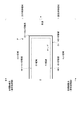
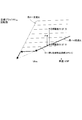
- FIG. 1 is an overall configuration diagram illustrating an FF hybrid vehicle to which an electric vehicle control device and an electric vehicle control method according to a first embodiment are applied. It is a figure which shows an example of the mode transition map set in Example 1. FIG. It is a figure which shows an example of the shift schedule map used in Example 1.
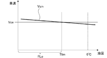
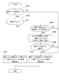
- FIG. 3 is a flowchart showing a flow of slip-in control processing in the first embodiment. It is a characteristic view which shows the relationship between the slip-in vehicle speed with respect to the oil temperature in Example 1, and the relationship between this slip-in vehicle speed and a coast regeneration completion vehicle speed.
- Example 1 It is a characteristic view which shows the share ratio of the coast regeneration torque, the cooperative regeneration torque, and the mechanical brake (hydraulic braking torque) in the weak coast regeneration mode and the strong coast regeneration mode in the first embodiment.
- 3 is a map showing a target driving force characteristic with respect to a vehicle speed in a weak coast regeneration mode and a target driving force characteristic with respect to a vehicle speed in a strong coast regeneration mode in Example 1.
- Example 1 it is a flowchart which shows the flow of the strong coast regeneration mode cancellation process performed when oil temperature is lower than a low temperature threshold (when a slip-in vehicle speed is higher than a coast regeneration completion vehicle speed). It is a time chart which shows the operation example at the time of the oil temperature of the comparative example with Example 1 being low temperature from a low temperature threshold value.
- 6 is a time chart showing an operation example when the oil temperature of Example 1 is lower than a low temperature threshold value. 6 is a time chart showing an operation example when the oil temperature becomes lower than a low temperature threshold during deceleration in the first embodiment.
- Example 1 shown in the drawings.
- Example 1 First, the configuration will be described.
- the control device and the control method for an electric vehicle according to the first embodiment are applied to an FF hybrid vehicle including a parallel hybrid drive system called a 1-motor / 2-clutch.
- the configuration of the FF hybrid vehicle to which the control method of the first embodiment is applied is described as “detailed configuration of drive system”, “detailed configuration of operation mode”, “detailed configuration of control system”, and “control system for electric vehicle”.
- the drive system of the FF hybrid vehicle includes an engine Eng, a first clutch CL1, a motor generator MG, a second clutch CL2, a continuously variable transmission CVT, a final gear FG, and a left drive.
- a wheel LT and a right drive wheel RT are provided.
- the FF hybrid vehicle is provided with a brake hydraulic pressure actuator BA.
- the engine Eng is torque-controlled so that the engine torque matches the command value by controlling the intake air amount by the throttle actuator, the fuel injection amount by the injector, and the ignition timing by the spark plug. Further, when the engine Eng is not in the combustion operation state but is in the cranking operation state only by engaging the first clutch CL1, friction torque is generated due to frictional sliding resistance between the piston and the inner wall of the cylinder.
- the first clutch CL1 is interposed in a drive transmission path between the engine Eng and the motor generator MG.
- the first clutch CL1 for example, a normally open dry multi-plate clutch is used, and the engagement / slip engagement / release between the engine Eng and the motor generator MG is performed. If the first clutch CL1 is in the fully engaged state, motor torque + engine torque is transmitted to the second clutch CL2, and if it is in the released state, only motor torque is transmitted to the second clutch CL2.
- the engagement / slip engagement / release of the first clutch CL1 is performed by hydraulic control in which a transmission torque (clutch torque capacity) is generated according to the clutch hydraulic pressure (pressing force).
- the motor generator MG has an AC synchronous motor structure, and performs motor torque control and motor rotation speed control when starting and running, and collecting (charging) vehicle kinetic energy to the battery 9 by regenerative brake control during braking and deceleration. Is to do.
- the second clutch CL2 is a normally open wet multi-plate clutch or wet multi-plate brake provided in the forward / reverse switching mechanism of the continuously variable transmission CVT, and the transmission torque (clutch torque capacity) according to the clutch hydraulic pressure (pressing force). ) Occurs.
- the second clutch CL2 transmits the torque output from the engine Eng and the motor generator MG (when the first clutch CL1 is engaged) to the left and right drive wheels LT, RT via the continuously variable transmission CVT and the final gear FG. Communicate.
- the second clutch CL2 is set between the continuously variable transmission CVT and the left and right drive wheels LT, RT, in addition to setting the drive transmission path between the motor generator MG and the continuously variable transmission CVT.
- the drive transmission path may be set.
- the continuously variable transmission CVT is a belt-type continuously variable transmission having a primary pulley PrP, a secondary pulley SeP, and a pulley belt BE.
- the primary pulley PrP is connected to the transmission input shaft input.
- the secondary pulley SeP is connected to the transmission output shaft output.
- the pulley belt BE is bridged between the primary pulley PrP and the secondary pulley SeP.
- the primary pulley PrP has a fixed sheave fixed to the transmission input shaft input and a movable sheave slidably supported on the transmission input shaft input.
- the secondary pulley SeP has a fixed sheave fixed to the transmission output shaft output and a movable sheave supported slidably on the transmission output shaft output.
- the pulley belt BE is a metal belt wound between the primary pulley PrP and the secondary pulley SeP, and is sandwiched between the fixed sheave and the movable sheave.
- a pin type belt or a VDT type belt is used as the pulley belt BE.
- the pulley width of both the pulleys PrP and SeP is changed, and the diameter of the holding surface of the pulley belt BE is changed to freely control the gear ratio (pulley ratio).
- the gear ratio changes to the low side.
- the gear ratio changes to the high side.
- the above-described operation for changing the pulley width of the continuously variable transmission CVT is driven by the hydraulic pressure discharged from the oil pump OP.
- the oil pump OP is rotated and driven by a motor generator MG as shown in the drawing, and supplies oil to the continuously variable transmission CVT and the second clutch CL2 as a hydraulic drive unit.
- the amount of oil supplied by the oil pump OP is an amount corresponding to the rotational speed of the motor generator MG.
- the brake hydraulic pressure actuator BA is provided in a hydraulic path that connects a master cylinder MC that generates a master cylinder pressure by depressing the brake pedal BP and a wheel cylinder WC that generates a braking force in each wheel.
- the brake hydraulic pressure actuator BA includes a valve for reducing the wheel cylinder pressure and a valve for supplying hydraulic pressure from a hydraulic pressure source such as a pump (not shown) to the wheel cylinder WC.
- the wheel cylinder pressure can be arbitrarily increased or decreased. It is configured.
- EV mode electric drive mode
- HEV mode hybrid travel mode
- WSC mode hybrid travel mode
- the “EV mode” is an electric vehicle mode in which the first clutch CL1 is disengaged and the second clutch CL2 is engaged and only the motor generator MG is used as a drive source, and traveling in the “EV mode” is referred to as “EV traveling”.
- the “HEV mode” is a hybrid vehicle mode in which both the clutches CL1 and CL2 are engaged and the engine Eng and the motor generator MG are used as driving sources, and traveling in the “HEV mode” is referred to as “HEV traveling”.
- the “WSC mode” is a CL2 slip engagement mode in which the second clutch CL2 is slip-engaged in the “HEV mode” or the “EV mode”.
- the “WSC mode” is a mode that is set by not having a rotation difference absorbing element such as a torque converter in the hybrid drive system.
- the second clutch CL2 is slip-engaged in the start and stop areas in the “HEV mode” in which the minimum engine speed is the engine idle engine speed, and when the required engine speed of the oil pump OP is secured in the EV mode. .
- the rotational speed of motor generator MG and the differential rotation between the input rotational speed of continuously variable transmission CVT and the input rotational speed of continuously variable transmission CVT are absorbed.
- motor generator MG In the “EV mode” and “HEV mode”, when the motor generator MG is controlled to the power running side, the motor generator MG is used as a travel drive source (motor). When controlling motor generator MG to the regeneration side, motor generator MG is used as a power generation drive source (generator).
- Controlling the motor generator MG to the power running side means that the motor generator MG is in a power running state in which power is supplied from the inverter 8 to the motor generator MG and the left and right drive wheels LT, RT are driven by the motor generator MG. It is to control MG.
- Controlling the motor generator MG to the regeneration side means that the motor generator MG is controlled so that the rotational energy of the motor generator MG and the left and right drive wheels LT and RT flows into the inverter 8. That is.
- the mode transition between the “EV mode” and the “HEV mode” is performed using the target driving force and the mode transition map shown in FIG. That is, when the motor generator MG is controlled to the power running side, the operating point P corresponding to the target driving force is set on the power running control region set above the target driving force zero axis shown in FIG. “EV mode” is selected when the operating point P is within the EV region, and “HEV mode” is selected when the operating point P is within the HEV region.
- the operating point P corresponding to the target driving force is set on the regeneration control region set below the target driving force zero axis shown in FIG. “EV mode” is selected when the operating point P is within the EV region, and “HEV mode” is selected when the operating point P is within the HEV region.
- the “EV region” is an electric travel region set in a region where the absolute value of the target driving force is small
- the “HEV region” is a region where the absolute value of the target driving force is larger than the EV region. This is the set hybrid travel area.
- the EV area and the HEV area are partitioned by an EV / HEV switching line indicated by a thick line in FIG.
- the control system of the FF hybrid vehicle includes an integrated controller 14, a transmission controller 15, a clutch controller 16, an engine controller 17, a motor controller 18, a battery controller 19, and a brake controller 20. It is equipped with.
- a brake sensor 21, a lever position detection sensor 22, a vehicle speed sensor 23, an automatic travel setting switch sensor 24, and a regeneration mode changeover switch 29 are provided.
- the integrated controller 14 calculates the target driving force from the battery state, accelerator opening, vehicle speed (a value synchronized with the transmission output speed), hydraulic oil temperature, target vehicle speed, and the like. Based on the calculation result of the target driving force, the command value for each actuator (motor generator MG, engine Eng, first clutch CL1, second clutch CL2, continuously variable transmission CVT, brake hydraulic actuator BA) is calculated, The data is transmitted to each of the controllers 15, 16, 17, 18, 19, and 20 via the CAN communication line 25.
- the transmission controller 15 performs shift control by controlling the pulley hydraulic pressure supplied to the primary pulley PrP and the secondary pulley SeP of the continuously variable transmission CVT so as to achieve the shift command from the integrated controller 14.
- the shift control by the transmission controller 15 uses the shift schedule map shown in FIG. 3 and the driving point by the vehicle speed VSP and the target driving force DF, and the target primary rotational speed by the driving point (VSP, DF) on the shift schedule. This is done by determining Npri *.
- the speed change schedule changes the speed ratio within a speed ratio range based on the lowest speed ratio and the highest speed ratio according to the operating point (VSP, DF).
- the lowest gear ratio is the gear ratio corresponding to the lowest speed, and is the largest value as the gear ratio.
- the highest gear ratio is the gear ratio corresponding to the highest speed, and is the smallest value as the gear ratio. Further, when the vehicle is stopped, low return control for returning to the lowest gear ratio along the low return control speed change line is executed.
- the clutch controller 16 inputs sensor information from the engine speed sensor 11, the motor speed sensor 6, the transmission input speed sensor 7, etc., and outputs clutch hydraulic pressure command values to the first clutch CL1 and the second clutch CL2. To do. Thereby, the pressing force of the first clutch CL1 is set, and the pressing force of the second clutch CL2 is set.
- the engine controller 17 inputs sensor information from the engine speed sensor 11 and controls the torque of the engine Eng so as to achieve the engine torque command value from the integrated controller 14.
- the motor controller 18 outputs a control command to the inverter 8 so as to achieve the motor torque command value and the motor rotation speed command value from the integrated controller 14, and performs motor torque control and motor rotation speed control of the motor generator MG. .
- Inverter 8 performs DC / AC mutual conversion, and changes the discharge current from battery 9 to the drive current of motor generator MG. Further, the generated current from motor generator MG is converted into a charging current for battery 9.
- the motor controller 18 controls the rotation speed of the motor generator MG so that the oil pump OP can discharge the required amount of oil even when the engine Eng is stopped in a non-driven state.
- the clutch controller 16 performs control to cause the second clutch CL2 to slip so that the stopped state can be maintained even if the motor generator MG is rotating.
- the battery controller 19 manages the charge capacity SOC of the battery 9 and transmits the SOC information to the integrated controller 14 and the engine controller 17.
- the brake controller 20 inputs sensor information from the brake sensor 21 and outputs a braking force command to the brake hydraulic pressure actuator BA so as to achieve the braking force command from the integrated controller 14. I do.
- cooperative regenerative braking control with a motor regenerative torque of a motor generator MG described later is executed.
- this cooperative regenerative braking control the required braking force when the driver performs a braking operation by the brake pedal BP is determined based on the hydraulic braking torque generated by the brake hydraulic actuator BA and the cooperation by the motor generator MG. Control is performed so as to be obtained together with the regenerative braking torque. Further, at the end of the cooperative regenerative braking control, a replacement control for increasing the hydraulic braking torque while executing the cooperative regenerative braking torque is executed.
- the automatic travel setting switch sensor 24 is a sensor that detects an operation signal of an automatic travel switch that is turned ON / OFF by the driver. When the automatic travel switch is turned ON, an automatic travel command is transmitted to the integrated controller 14. Thereby, the automatic travel mode is set. When the automatic travel switch is turned off, the automatic travel setting switch sensor 24 transmits an automatic travel release command to the integrated controller 14. Thereby, the setting of the automatic travel mode is canceled and the manual travel mode is set.
- the automatic travel mode when the driver operates the accelerator pedal and the automatic travel setting switch is turned on when the vehicle speed reaches a predetermined vehicle speed or higher, the arbitrary vehicle speed is set as the target vehicle speed. Thereafter, when a preceding vehicle is detected ahead based on information from a radar sensor or the like (not shown), the detected vehicle speed of the preceding vehicle is set as the target vehicle speed. Even if the driver does not turn off the automatic travel switch, the automatic travel setting switch sensor 24 sends an automatic travel cancellation command to the integrated controller 14 in response to a predetermined operation by the driver such as depressing the brake pedal BP. Also good. Also in this case, the setting of the automatic travel mode is canceled and the mode is switched to the manual travel mode.
- the clutch controller 16 executes slip-in control for bringing the second clutch CL2 into a slip engagement state when the vehicle speed decreases to the slip-in vehicle speed Vsin during deceleration.
- FIG. 4 shows the flow of slip-in control processing executed by the clutch controller 16 during deceleration.
- step S101 necessary data is received from each of the controllers 14 to 20 via the CAN communication line 25, and the process proceeds to step S102.
- “necessary data” refers to data from the transmission input rotational speed sensor 7, the oil temperature sensor 12, the accelerator opening sensor 10, the brake sensor 21, the vehicle speed sensor 23, and the like. That is, accelerator opening information, brake operation information, vehicle speed information, transmission input rotation speed information, oil temperature information, and the like are used as necessary information.
- the integrated controller 14 holds mode information of “HEV mode” and “EV mode”.
- step S102 following the data reception in step S101, it is determined whether or not there is a slip-in request. If YES (slip-in request is present), the process proceeds to step S103, and if NO (slip-in request is not present). One process is completed.
- the “slip-in request” is determined as “no slip-in request” while the vehicle speed exceeds the slip-in vehicle speed Vsin at the time of deceleration, and “slip-in request” is issued when the vehicle speed becomes equal to or less than the slip-in vehicle speed Vsin. Is determined.
- This “slip-in vehicle speed” is the vehicle speed before the gear backlash control is terminated when performing the cooperative regeneration control ⁇ gear backlash control ⁇ second clutch slip-in control in order as the vehicle speed decreases during deceleration in the coasting scene.
- the “slip-in vehicle speed” is set to a lower vehicle speed when the vehicle is decelerating in the “EV mode” accompanied by the cooperative regeneration control than when the vehicle is decelerated in the “HEV mode” accompanied by the cooperative regeneration control.
- the slip-in vehicle speed Vsin is set on the higher vehicle speed side than the case where the oil temperature is higher as the oil temperature is lower, according to the oil temperature.
- step S103 following the determination that there is a slip-in request in step S102, a torque capacity command for reducing the engagement hydraulic pressure of the second clutch CL2 is output, and the process proceeds to step S104.
- the “torque capacity command” is a command value that becomes higher than the motor torque and has a capacity that the second clutch CL2 does not slip, and becomes a capacity that becomes lower than the motor torque and that allows the second clutch CL2 to slide. .
- step S104 following the lowering of the engagement hydraulic pressure of the second clutch CL2 in step S103, the motor torque is calculated, a command for obtaining the motor torque is output from the motor controller 18 to the inverter 8, and the process proceeds to step S105.
- step S105 following the motor torque command output in step S104, it is determined whether or not the slip determination of the second clutch C2 has been made. If YES (the second clutch slip determination is present), the flow of one process is terminated, and if NO (second clutch slip determination is not present), the process returns to step S102.
- slip determination monitors the slip amount of the second clutch CL2, and determines that the slip determination is present when the slip amount is equal to or greater than the slip determination threshold.
- the motor regenerative torque control is control for generating a predetermined coast regenerative torque by the motor generator MG during coasting (hereinafter referred to as coasting). Further, when the coast regeneration control is executed, if the vehicle speed is reduced to a preset coast end speed, a coast regeneration end process is executed in which the coast regeneration power is set to zero.
- the coast regeneration control is a control for generating a deceleration force by the motor regeneration torque when the vehicle is decelerated.
- the weak coast regeneration mode and the strong coast regeneration mode can be selected by the regeneration mode changeover switch 29.
- FIG. 6 shows a comparison of the share ratio of coast regeneration / brake coordination regeneration / mechanical brake (brake hydraulic actuator BA) when the weak coast regeneration mode is selected and when the strong coast regeneration mode is selected.
- FIG. 7 shows an example of a coast target driving force characteristic with respect to the vehicle speed when the weak coast regeneration mode is selected and a coast target driving force characteristic with respect to the vehicle speed when the strong coast regeneration mode is selected.
- the coast regeneration mode configuration when the accelerator is released will be described with reference to FIGS. 6 and 7.
- the braking force generation region by the weak coast torque TLo that is the coast regeneration amount by the accelerator release operation is set to the negative target driving force region by the engine brake equivalent.
- the weak coast torque TLo characteristic in the “weak coast regeneration mode” changes while maintaining the weak coast torque TLo equivalent to the engine brake when the vehicle speed VSP decreases due to deceleration, as shown by the broken line characteristic in FIG. .
- the coast regeneration amount gradually decreases as the vehicle approaches a stop, and shifts to a positive target driving force (creep torque) when the vehicle reaches a stop region below the coast regeneration end vehicle speed.
- the weak coast torque TLo is set to a value that does not cause the driver to feel uncomfortable even if the weak coast torque TLo changes from the weak coast torque TLo to 0 at the end of coast regeneration. .
- the strong coast torque THi characteristic in the “strong coast regeneration mode” indicates that the coast regeneration amount (strong coast torque THi) corresponding to engine braking is reduced when the vehicle speed VSP decreases due to deceleration, as shown by the solid line characteristic in FIG. Increase.
- the increased strong coast torque THi is suddenly reduced, and when the vehicle enters a stop region below the predetermined course regeneration end vehicle speed, it shifts to a positive target driving force (creep torque).
- the target driving force characteristics of the accelerator opening APO in the middle and low opening range are also shifted to the negative target driving force side than in the “weak coast regeneration mode”. Yes.
- the weak coast torque TLo When the “weak coast regeneration mode” is selected, if the vehicle is decelerated by the accelerator release operation, the weak coast torque TLo remains constant up to the low vehicle speed range. Then, after reaching the low vehicle speed range, as shown by the arrow A in FIG. 7, the weak coast torque TLo gradually decreases with a gradual decrease gradient as the vehicle speed decreases.
- the strong coast regeneration mode when the “strong coast regeneration mode” is selected, as shown by the arrow B in FIG. 7, when the vehicle is decelerated by the accelerator release operation, the strong coast torque THi increases due to a steep increase gradient due to a decrease in the vehicle speed. Then, after passing through the maximum coast regeneration amount region, as shown by an arrow C in FIG. 7, the strong coast torque THi decreases due to a steep decrease gradient due to a decrease in the vehicle speed.
- the “strong coast regeneration mode” does not require a brake pedal operation in most deceleration scenes, and can control the braking force by the accelerator return / release operation.
- the “strong coast regeneration mode” is sometimes referred to as “one pedal mode” in which driving / braking is controlled by accelerator work to an accelerator pedal (not shown).
- coast regeneration torque is a coast regeneration amount that is effective when the accelerator is off and the brake is off.
- the “cooperative regeneration torque” is a brake cooperative regeneration amount that is effective when the accelerator is OFF and the brake is ON.
- the total value of the coast regeneration torque (TLo, THi) and the cooperative regeneration torque is controlled to be within the range of the motor regeneration amount upper limit value that can be generated by the motor generator MG.
- “Mechanical brake” is a hydraulic braking torque that is compensated when the required braking force cannot be satisfied only by the regeneration amount (coast regeneration amount + brake cooperative regeneration amount) when the accelerator is OFF and the brake is ON.
- the hydraulic braking torque is braking torque generated in the wheel cylinder WC by the hydraulic pressure supplied from the master cylinder MC and the brake hydraulic actuator BA.
- the coast regeneration end timing will be described. As shown in FIG. 7, in both the weak coast regeneration mode and the strong coast regeneration mode, the absolute value is decreased until the coast regeneration torque becomes zero at a predetermined coast regeneration end vehicle speed Vce before stopping due to deceleration. Let Further, after the coast regenerative torque is set to 0, as described above, the positive target driving force (creep torque) is shifted to.
- the slip-in vehicle speed Vsin is set higher in the low temperature region than the low temperature threshold Tlim set in the extremely low temperature region of 0 ° C. or less as compared to the coast regeneration end vehicle speed Vce.
- the slip-in vehicle speed Vsin is set lower than the coast regeneration end vehicle speed Vce in a temperature range equal to or higher than the low temperature threshold Tlim.
- the motor controller 18 executes the strong coast regeneration mode canceling process for canceling this under a predetermined condition.
- the predetermined condition for executing the strong coast regeneration mode canceling process is when the slip-in vehicle speed Vsin is higher than the coast regeneration end vehicle speed Vce, in other words, when the oil temperature is lower than the low temperature threshold Tlim.
- the coast regeneration torque is set to the weak coast torque TLo used in the weak coast regeneration mode, which is smaller than the strong coast torque THi used in the normal condition other than the predetermined condition.
- step S301 it is determined whether or not the strong coast regeneration mode is currently selected by the regeneration mode switch 29. If the strong coast regeneration mode is selected, the process proceeds to step S302. If the strong coast regeneration mode is not selected, the process proceeds to step S307, and the map for the weak coast regeneration mode (dotted line in FIG. 7). Regenerative torque is generated based on
- step S302 which proceeds to step S301 when the strong coast mode is selected, it is determined whether the oil temperature is higher than the low temperature threshold Tlim (whether the slip-in vehicle speed Vsin is lower than the coast regeneration end vehicle speed Vce).
- step S303 a strong coast torque THi is generated based on the map for the strong coast regeneration mode (solid line in FIG. 7).
- step S302 when the oil temperature is equal to or lower than the low temperature threshold Tlim in step S302 (when the slip-in vehicle speed Vsin is higher than the coast regeneration end vehicle speed Vce), the process proceeds to step S304, and is the regeneration operation already performed with the strong coast torque THi? Judge whether or not.
- step S304 if the regeneration is not being performed with the strong coast torque THi, the process proceeds to step S305. If the regeneration is already being performed with the strong coast torque THi, the process proceeds to step S305. Further, in step S305, the coast regenerative torque (motor regenerative torque) is decreased toward the weak coast torque TLo (decreasing the absolute value) at a change speed (inclination Kv) at which the change in the vehicle deceleration is equal to or less than an allowable value. ).
- step S306 When the motor regeneration torque reaches the weak coast torque TLo (YES in step S306), the process proceeds to step S307 to perform coast regeneration based on the map for the weak coast regeneration mode, and then perform one process. finish.
- the coast regenerative torque when the oil temperature is equal to or lower than the low temperature threshold Tlim is set as the weak coast torque TLo, and is controlled to be smaller than the strong coast torque THi that is the coast regenerative torque when the oil temperature is higher than the low temperature threshold Tlim (S302 ⁇ S304 ⁇ S307).
- the strong coast regeneration mode when the oil temperature is equal to or lower than the low temperature threshold Tlim, when the strong coast regeneration mode is canceled and the coast regeneration torque is controlled to the weak coast torque TLo, if the strong coast torque THi is already generated, the coast regeneration torque is reduced. Decrease gently. That is, the high coast torque THi is decreased to the weak coast torque TLo at a change speed (inclination Kv) at which the change in the vehicle deceleration is equal to or less than an allowable value (S304 ⁇ S305).
- FIG. 9 shows that the vehicle is decelerated in the strong coast regeneration mode in a state where the oil temperature is lower than the low temperature threshold Tlim and the slip-in vehicle speed Vsin is set higher than the coast regeneration end vehicle speed Vce. It is a time chart which shows operation
- the clutch controller 16 sets the slip-in vehicle speed Vsin to a higher speed side as the temperature becomes lower based on the characteristics shown in FIG. 5 so that the slip start timing of the second clutch CL2 actually becomes an appropriate timing. To control. For this reason, in the low temperature range RLo where the oil temperature is lower than the low temperature threshold value Tlim, the slip-in vehicle speed Vsin is set to be higher than the coast regeneration end vehicle speed Vce.
- the slip-in control is performed in a state where the vehicle speed becomes the slip-in vehicle speed Vsin at the time t01 before the time t02 when the coast regeneration ends and the coast regeneration is performed with the strong coast torque THi. Will start.
- FIG. 11 shows a case where the vehicle is decelerated and stopped in the strong coast regeneration mode in a state where the oil temperature is lower than the low temperature threshold Tlim and the slip-in vehicle speed Vsin is set higher than the coast regeneration end vehicle speed Vce. It is a time chart which shows the operation
- the vehicle in the low temperature region RLo where the oil temperature is lower than the low temperature threshold value Tlim, even when the strong coast regeneration mode is selected, the vehicle is weak based on the weak coast regeneration mode map (dotted line in FIG. 7) during deceleration.
- a coast torque TLo is generated. This is based on the processing of S301 ⁇ S302 ⁇ S304 ⁇ S307 in FIG.
- the slip-in control is started in a state where the vehicle speed becomes the slip-in vehicle speed Vsin at the time t11 before the time t12 when the coast regeneration ends and the coast regeneration is performed with the weak coast torque TLo. .
- the difference in regenerative torque before and after slip-in becomes smaller than that in FIG. 10A.
- the deceleration change (slip-in shock) that occurs during the slip-in control of the second clutch CL2 is smaller than that in the comparative example, and the uncomfortable feeling given to the occupant can be suppressed.
- FIG. 12 shows the first embodiment in the case where the vehicle temperature is decelerated and stopped in the strong coast regeneration mode, and at time t21, the oil temperature decreases from a temperature higher than the low temperature threshold Tlim to a temperature lower than the low temperature threshold Tlim. It is a time chart which shows operation
- the strong coast torque THi is generated based on the strong coast regeneration mode (the processing of S301 ⁇ S302 ⁇ S303 in FIG. 8).
- the process of S301 ⁇ S302 ⁇ S304 ⁇ S305 is executed at the time t21 when the oil temperature falls below the low temperature threshold Tlim.
- the coast regenerative torque is gradually decreased from the strong coast torque THi to the weak coast torque TLo at a change speed (inclination Kv) where the change in the vehicle deceleration is less than or equal to the allowable value.
- the coast regenerative torque is gradually reduced at a change speed Kv in which the change in vehicle deceleration is less than or equal to the allowable value, the occupant can be changed even if the coast regenerative torque is changed from the strong coast torque THi to the weak coast torque TLo. You can avoid giving a sense of incongruity.
- the vehicle speed reaches the slip-in vehicle speed Vsin, and the slip-in control is executed for the second clutch CL2.
- the torque change is small, and the discomfort given to the occupant can be suppressed.
- the effects of the control device for the electric vehicle and the control method for the electric vehicle according to the first embodiment are listed below.
- the control device for the electric vehicle according to the first embodiment is A second clutch CL2 as a friction clutch disposed between the motor generator MG for driving the vehicle and the left and right drive wheels;
- An oil pump OP that is driven by a motor generator MG and supplies oil toward a continuously variable transmission CVT and a second clutch CL2 as a hydraulic drive unit of the vehicle;
- An electric vehicle control device comprising: A motor controller 18 as a motor regeneration control unit that generates coast regeneration torque in the motor generator MG during coasting of the vehicle and sets the coast regeneration torque to 0 at a predetermined coast regeneration end vehicle speed Vce before the vehicle stops; ,
- An oil supply control unit (motor controller 18) that drives the motor generator MG at a predetermined rotation speed Norpm that enables the oil pump OP to supply oil while the vehicle is stopped;
- a clutch controller 16 serving as a clutch control unit that performs slip-in control (processing of the
- a slip-in vehicle speed setting unit that is included in the clutch controller 16 and sets a slip-in vehicle speed;
- the motor controller 18 uses a coast regeneration torque when the slip-in vehicle speed Vsin is higher than the coast regeneration end vehicle speed Vce, and a strong coast torque THi that is a coast regeneration torque when the slip-in vehicle speed Vsin is lower than the coast regeneration end vehicle speed Vce. Is made smaller (execution part of the strong coast regeneration mode cancellation process in FIG. 8).
- the control device for the electric vehicle of Example 1 is:
- the slip-in vehicle speed setting unit sets the slip-in vehicle speed Vsin on the higher speed side as the oil temperature becomes lower according to the temperature of the oil, and finishes coast regeneration with the slip-in vehicle speed Vsin when the oil temperature is higher than the low temperature threshold Tlim.
- the motor controller 18 uses a coast regeneration torque when the slip-in vehicle speed Vsin is higher than the coast regeneration end vehicle speed Vce, and a strong coast torque THi that is a coast regeneration torque when the slip-in vehicle speed Vsin is lower than the coast regeneration end vehicle speed Vce.
- the coast regenerative torque when the oil temperature is equal to or lower than the low temperature threshold Tlim is made smaller than the coast regenerative torque (strong coast torque THi) when the oil temperature is higher than the low temperature threshold Tlim.
- the vertical relationship between the slip-in vehicle speed Vsin and the coast regeneration end vehicle speed Vce can be determined based on the oil temperature. That is, when the oil temperature is equal to or lower than the low temperature threshold Tlim, it can be determined that the slip-in vehicle speed Vsin is higher than the coast regeneration end vehicle speed Vce. Therefore, the slip-in vehicle speed Vsin and the coast regeneration end vehicle speed Vce can be easily detected, and the configuration can be simplified.
- the control device for the electric vehicle of the first embodiment is The motor controller 18 According to the output of the regeneration mode changeover switch 29, the coast regeneration torque is a weak coast regeneration mode in which the weak coast torque TLo is set, and the strong coast regeneration mode in which the strong coast torque THi is obtained that provides a deceleration force greater than the weak coast torque TLo. , And can be switched to In the strong coast regeneration mode, when the oil temperature is equal to or lower than the low temperature threshold Tim, when the coast regeneration torque is controlled to be small, the strong coast regeneration mode is canceled and the weak coast regeneration mode is set (S302 ⁇ S304 ⁇ S307). ).
- the coast regeneration is set to the weak coast regeneration mode before the end. Therefore, the vehicle deceleration change at the time of performing slip-in control in a coast regeneration state can be suppressed. Further, in reducing the coast regeneration torque, the mode is simply switched, and the existing control processing can be used as it is, and the configuration can be simplified.
- the control device for the electric vehicle is The motor controller 18
- the oil temperature is lower than the low temperature threshold Tlim and the coast regenerative torque is changed from the strong coast regenerative mode to the weak coast regenerative mode
- the change in the vehicle deceleration is less than the allowable value.
- the control device for the electric vehicle of Example 1 is:
- the second clutch C2 is included in the hydraulic pressure supply destination of the oil pump OP. Therefore, when the oil temperature decreases, the amount of torque change during slip-in control when the slip-on vehicle speed Vsin of the second clutch CL2 is higher than the coast regeneration end vehicle speed Vce can be suppressed. Thereby, the deceleration change of the vehicle at the time of slip-in control can also be suppressed, and the uncomfortable feeling given to the passenger can be suppressed.
- the control device for the electric vehicle according to the first embodiment is
- the oil pressure supply destination of the oil pump OP includes a continuously variable transmission CVT provided in a drive transmission system between the motor generator MG and the left and right drive wheels LT, RT.
- a continuously variable transmission CVT is included in the hydraulic pump OP supply destination, a large amount of discharge is required even when the vehicle is stopped, and the second clutch CL2 is slipped by securing the rotation speed of the motor generator MG. It is necessary to let Thus, the above-mentioned effect can be acquired in what slips 2nd clutch CL2.
- a second clutch CL2 as a friction clutch disposed between the motor generator MG for driving the vehicle and the left and right drive wheels;
- An oil pump OP that is driven by a motor generator MG and supplies oil toward a continuously variable transmission CVT and a second clutch CL2 as a hydraulic drive unit of the vehicle;
- An electric vehicle control device comprising: A motor controller 18 as a motor regeneration control unit that generates coast regeneration torque in the motor generator MG during coasting of the vehicle and sets the coast regeneration torque to 0 at a predetermined coast regeneration end vehicle speed Vce before the vehicle stops; , An oil supply control unit (motor controller 18) that drives the motor generator MG at a predetermined rotation speed Norpm that enables the oil pump OP to supply oil while the vehicle is stopped;
- a clutch controller 16 serving as a clutch control unit that performs slip-in control (processing of the flowchart of FIG.
- a slip-in vehicle speed setting unit which is included in the clutch controller 16 and sets a slip-in vehicle speed;
- Of strong coast regeneration mode it is possible to reduce the amount of torque change when the slip-in control is performed on the second clutch CL2. Thereby, the deceleration change of the vehicle at the time of slip-in control can also be suppressed, and the uncomfortable feeling given to the passenger can be suppressed.
- the present invention is not limited to this.
- the electric vehicle control device and electric vehicle control method of the present disclosure need only include a regenerative motor and a continuously variable transmission that executes low return control, and are not limited to hybrid vehicles, and drive only the motor. It can also be applied to an electric vehicle as a source.
- a parallel hybrid vehicle is not limited to the one-motor / two-clutch type shown in the embodiment.
- the continuously variable transmission and the second clutch as the friction clutch are shown as the hydraulic drive unit to which the oil pump supplies oil, but the present invention is not limited to this.
- a transmission other than a continuously variable transmission may be used as the transmission.
- a configuration may be adopted in which a transmission is not provided.
- the friction clutch may not be included in the hydraulic drive unit.
- the coast regeneration torque when the slip-in vehicle speed is higher than the coast regeneration end vehicle speed is controlled to be smaller than the strong coast torque that is the coast regeneration torque when the slip-in vehicle speed is lower than the coast regeneration end vehicle speed.
- the weak coast regeneration mode is controlled to weak coast torque.
- the reduction amount is different from the weak coast torque in the weak coast regeneration mode. May be set in advance. In this case, either a larger value or a smaller value than the weak coast torque may be used according to the deceleration change during the slip-in control.
- the present invention can also be applied to those in which such a mode is not set.
- the present invention can be applied to a control that generates a coast regenerative torque at the slip-in vehicle speed and that wants to suppress a change in deceleration during the slip-in control.
- the state in which the slip-in vehicle speed is higher than the coast regeneration end vehicle speed is determined based on the oil temperature, but this determination is not limited to this. In short, since it is only necessary to determine that the slip-in vehicle speed is higher than the coast regeneration end vehicle speed, the slip-in vehicle speed may be compared with the coast start / end vehicle speed.
Landscapes
- Engineering & Computer Science (AREA)
- Power Engineering (AREA)
- Transportation (AREA)
- Mechanical Engineering (AREA)
- Electric Propulsion And Braking For Vehicles (AREA)
- Hydraulic Clutches, Magnetic Clutches, Fluid Clutches, And Fluid Joints (AREA)
- Hybrid Electric Vehicles (AREA)
Abstract
低温下での摩擦クラッチのスリップイン制御時の車両減速度変化を抑えることが可能な電動車両の制御装置を提供する。 モータジェネレータ(MG)と左右駆動輪との間に配置された第2クラッチ(CL2)と、モータジェネレータ(MG)により駆動されるオイルポンプ(OP)と、車両の惰性走行時にモータジェネレータ(MG)にコースト回生トルクを発生させ、かつ、所定のコースト回生終了車速(Vce)で、コースト回生トルクを0とするモータコントローラ(18)と、を備え、モータコントローラ(18)は、第2クラッチ(CL2)をスリップイン制御を行うスリップイン車速(Vsin)がコースト回生終了車速(Vce)よりも高い場合のコースト回生トルクを、スリップイン車速(Vsin)がコースト回生終了車速(Vce)よりも低い場合の強コーストトルク(THi)よりも小さくする電動車両の制御装置とした。
Description
本開示は、電動車両の制御装置および電動車両の制御方法に関するものである。
従来、走行用のモータの駆動により油圧差動部(変速機、クラッチなど)に油を供給するオイルポンプと、を備える電動車両の制御装置が知られている(例えば、特許文献1参照)。
また、このような従来技術では、車両の停車中においては、第2クラッチをスリップ締結することで、停車状態を維持しながらも、モータを所定回転数で回転させてオイルポンプによる油の供給を可能とすることができる。
また、このような従来技術では、車両の停車中においては、第2クラッチをスリップ締結することで、停車状態を維持しながらも、モータを所定回転数で回転させてオイルポンプによる油の供給を可能とすることができる。
ところで、車両の減速時には、所定のスリップイン車速以下に低下すると上記の第2クラッチをスリップさせる。また、このスリップイン車速は、低温になるほど第2クラッチの応答性が低下するため、停車前に確実に第2クラッチをスリップ状態とするには、低温になるほど高車速側に設定するのが好ましい。
しかしながら、低温時に、スリップイン車速を高速側に設定した結果、コースト回生終了車速よりも高車速に設定した場合、コースト回生中に、第2クラッチをスリップさせることになる。この場合、第2クラッチをスリップイン制御する前と、制御後とのトルク変化量が、コースト回生終了後にスリップイン制御を行う場合と比較して大きくなる。そして、このようにトルク変化量が大きいと、車両の減速度変化も大きくなり、乗員に違和感を与えるおそれがある。
しかしながら、低温時に、スリップイン車速を高速側に設定した結果、コースト回生終了車速よりも高車速に設定した場合、コースト回生中に、第2クラッチをスリップさせることになる。この場合、第2クラッチをスリップイン制御する前と、制御後とのトルク変化量が、コースト回生終了後にスリップイン制御を行う場合と比較して大きくなる。そして、このようにトルク変化量が大きいと、車両の減速度変化も大きくなり、乗員に違和感を与えるおそれがある。
本開示は、上記問題に着目してなされたもので、低温下での摩擦クラッチのスリップイン制御時の車両減速度変化を抑えることが可能な電動車両の制御装置および電動車両の制御方法を提供することを目的とする。
上記目的を達成するため、本開示の電動車両の制御装置は、
車両の走行用のモータと駆動輪との間に配置された摩擦クラッチと、
前記モータにより駆動され、前記車両の油圧駆動部に向けて前記油を供給するオイルポンプと、
前記車両の惰性走行時に前記モータにコースト回生トルクを発生させ、かつ、前記車両が停車する前の所定のコースト回生終了車速で、前記コースト回生トルクを0とするモータ回生制御部と、を備え、
モータ回生制御部は、摩擦クラッチを締結状態からスリップ状態に切り替えるスリップイン制御を行うスリップイン車速が前記コースト回生トルクを0とするコースト回生終了車速よりも高い場合のコースト回生トルクを、前記スリップイン車速が前記コースト回生終了車速よりも低い場合の前記コースト回生トルクよりも小さく制御する。
車両の走行用のモータと駆動輪との間に配置された摩擦クラッチと、
前記モータにより駆動され、前記車両の油圧駆動部に向けて前記油を供給するオイルポンプと、
前記車両の惰性走行時に前記モータにコースト回生トルクを発生させ、かつ、前記車両が停車する前の所定のコースト回生終了車速で、前記コースト回生トルクを0とするモータ回生制御部と、を備え、
モータ回生制御部は、摩擦クラッチを締結状態からスリップ状態に切り替えるスリップイン制御を行うスリップイン車速が前記コースト回生トルクを0とするコースト回生終了車速よりも高い場合のコースト回生トルクを、前記スリップイン車速が前記コースト回生終了車速よりも低い場合の前記コースト回生トルクよりも小さく制御する。
したがって、本開示の電動車両の制御装置では、コースト回生トルクを0とする前に、摩擦クラッチに対してスリップイン制御を行う場合のトルク変化量を小さく抑えることができる。これにより、スリップイン制御時の車両の減速度変化も抑え、乗員に与える違和感を抑えることができる。
以下、本開示の電動車両の制御装置および電動車両の制御方法を実施するための形態を、図面に示す実施例1に基づいて説明する。
(実施例1)
まず、構成を説明する。
実施例1の電動車両の制御装置および電動車両の制御方法は、1モータ・2クラッチと呼ばれるパラレルハイブリッド駆動系を備えるFFハイブリッド車両に適用したものである。以下、実施例1の制御方法が適用されたFFハイブリッド車両の構成を、「駆動系の詳細構成」、[運転モードの詳細構成]、[制御系の詳細構成]、[電動車両の制御装置の制御の説明]に分けて説明する。
まず、構成を説明する。
実施例1の電動車両の制御装置および電動車両の制御方法は、1モータ・2クラッチと呼ばれるパラレルハイブリッド駆動系を備えるFFハイブリッド車両に適用したものである。以下、実施例1の制御方法が適用されたFFハイブリッド車両の構成を、「駆動系の詳細構成」、[運転モードの詳細構成]、[制御系の詳細構成]、[電動車両の制御装置の制御の説明]に分けて説明する。
[駆動系の詳細構成]
FFハイブリッド車両の駆動系は、図1に示すように、エンジンEngと、第1クラッチCL1と、モータジェネレータMGと、第2クラッチCL2と、無段変速機CVTと、ファイナルギヤFGと、左駆動輪LTと、右駆動輪RTと、を備えている。さらに、このFFハイブリッド車両には、ブレーキ液圧アクチュエータBAが設けられている。
FFハイブリッド車両の駆動系は、図1に示すように、エンジンEngと、第1クラッチCL1と、モータジェネレータMGと、第2クラッチCL2と、無段変速機CVTと、ファイナルギヤFGと、左駆動輪LTと、右駆動輪RTと、を備えている。さらに、このFFハイブリッド車両には、ブレーキ液圧アクチュエータBAが設けられている。
エンジンEngは、スロットルアクチュエータによる吸入空気量とインジェクタによる燃料噴射量と、点火プラグによる点火時期の制御により、エンジントルクが指令値と一致するようにトルク制御される。また、エンジンEngは、燃焼運転状態ではなく、第1クラッチCL1を締結するだけでクランキング運転状態とすると、ピストンとシリンダー内壁との摩擦摺動抵抗などによりフリクショントルクを発生する。
第1クラッチCL1は、エンジンEngとモータジェネレータMGとの間の駆動伝達経路に介装されている。この第1クラッチCL1としては、例えば、ノーマルオープンの乾式多板クラッチなどが用いられ、エンジンEng~モータジェネレータMG間の締結/スリップ締結/解放を行なう。この第1クラッチCL1が完全締結状態ならモータトルク+エンジントルクが第2クラッチCL2へと伝達され、解放状態ならモータトルクのみが、第2クラッチCL2へと伝達される。なお、第1クラッチCL1の締結/スリップ締結/解放は、クラッチ油圧(押付力)に応じて伝達トルク(クラッチトルク容量)が発生する油圧制御にて行われる。
モータジェネレータMGは、交流同期モータ構造であり、発進時や走行時にモータトルク制御やモータ回転数制御を行うと共に、制動時や減速時に回生ブレーキ制御による車両運動エネルギのバッテリ9への回収(充電)を行なうものである。
第2クラッチCL2は、無段変速機CVTの前後進切替機構に設けられたノーマルオープンの湿式多板クラッチや湿式多板ブレーキであり、クラッチ油圧(押付力)に応じて伝達トルク(クラッチトルク容量)が発生する。この第2クラッチCL2は、無段変速機CVT及びファイナルギヤFGを介し、エンジンEng及びモータジェネレータMG(第1クラッチCL1が締結されている場合)から出力されたトルクを左右駆動輪LT,RTへと伝達する。なお、第2クラッチCL2は、図1に示すように、モータジェネレータMGと無段変速機CVTの間の駆動伝達経路に設定する以外に、無段変速機CVTと左右駆動輪LT,RTの間の駆動伝達経路に設定してもよい。
無段変速機CVTは、プライマリプーリPrPと、セカンダリプーリSePと、プーリベルトBEと、を有するベルト式無段変速機である。
なお、プライマリプーリPrPは、変速機入力軸inputに接続されている。セカンダリプーリSePは、変速機出力軸outputに接続されている。プーリベルトBEは、プライマリプーリPrPとセカンダリプーリSePとに架け渡されている。
なお、プライマリプーリPrPは、変速機入力軸inputに接続されている。セカンダリプーリSePは、変速機出力軸outputに接続されている。プーリベルトBEは、プライマリプーリPrPとセカンダリプーリSePとに架け渡されている。
プライマリプーリPrPは、変速機入力軸inputに固定された固定シーブと、変速機入力軸inputに摺動自在に支持された可動シーブと、を有している。セカンダリプーリSePは、変速機出力軸outputに固定された固定シーブと、変速機出力軸outputに摺動自在に支持された可動シーブと、を有している。
プーリベルトBEは、プライマリプーリPrPとセカンダリプーリSePとの間に巻き掛けられた金属ベルトであり、それぞれの固定シーブと可動シーブとの間に狭持される。ここで、プーリベルトBEとしては、ピン型ベルトやVDT型ベルトが使用される。
無段変速機CVTでは、両プーリPrP,SePのプーリ幅を変更し、プーリベルトBEの挟持面の径を変更して変速比(プーリ比)を自在に制御する。ここで、プライマリプーリPrPのプーリ幅が広くなると共に、セカンダリプーリSePのプーリ幅が狭くなると変速比がLow側に変化する。また、プライマリプーリPrPのプーリ幅が狭くなると共に、セカンダリプーリSePのプーリ幅が広くなると変速比がHigh側に変化する。
上述の無段変速機CVTのプーリ幅の変更動作は、オイルポンプOPから吐出される油圧により駆動される。このオイルポンプOPは、図示のように、モータジェネレータMGにより回転されて駆動し、油圧駆動部として無段変速機CVTおよび第2クラッチCL2に油を供給する。なお、オイルポンプOPによる油の供給量は、モータジェネレータMGの回転数に応じた量となる。
ブレーキ液圧アクチュエータBAは、ブレーキペダルBPの踏み込み操作によりマスタシリンダ圧を発生するマスタシリンダMCと、各輪で制動力を発生させるホイールシリンダWCとを結ぶ油圧経路に設けられている。なお、ブレーキ液圧アクチュエータBAは、ホイールシリンダ圧を減圧させるバルブや、図示を省略したポンプなどの液圧源の油圧をホイールシリンダWCに供給するバルブを備え、ホイールシリンダ圧を任意に増減圧可能に構成されている。
[運転モードの詳細構成]
実施例1のFFハイブリッド車両は、上述の駆動系により、運転モードとして、電気走行モード(以下、「EVモード」という。)と、ハイブリッド走行モード(以下、「HEVモード」という。)「WSCモード」を有する。
実施例1のFFハイブリッド車両は、上述の駆動系により、運転モードとして、電気走行モード(以下、「EVモード」という。)と、ハイブリッド走行モード(以下、「HEVモード」という。)「WSCモード」を有する。
「EVモード」は、第1クラッチCL1を開放し、第2クラッチCL2を締結してモータジェネレータMGのみを駆動源に有する電気自動車モードであり、「EVモード」による走行を「EV走行」という。
「HEVモード」は、両クラッチCL1,CL2を締結してエンジンEngとモータジェネレータMGを駆動源に有するハイブリッド車モードであり、「HEVモード」による走行を「HEV走行」という。
「WSCモード」は、「HEVモード」または「EVモード」において、第2クラッチCL2をスリップ締結するCL2スリップ締結モードである。なお、「WSCモード」は、ハイブリッド駆動系に、トルクコンバータなどの回転差吸収要素を持たないことで設定されるモードである。特に、最低回転数をエンジンアイドル回転数とする「HEVモード」における発進域や停車域において、およびEVモードにおいてオイルポンプOPの必要回転数を確保する場合には、第2クラッチCL2をスリップ締結する。これにより、モータジェネレータMGの回転数と、無段変速機CVTの入力回転数と無段変速機CVTの入力回転数の差回転を吸収する。
また、「EVモード」「HEVモード」では、モータジェネレータMGを力行側に制御するときは、モータジェネレータMGを走行駆動源(モータ)として用いる。また、モータジェネレータMGを回生側に制御するときは、モータジェネレータMGを発電駆動源(ジェネレータ)として用いる。
なお、「モータジェネレータMGを力行側に制御する」とは、インバータ8からモータジェネレータMGに電力を供給し、モータジェネレータMGで左右駆動輪LT,RTを駆動する力行状態となるように、モータジェネレータMGを制御することである。また、「モータジェネレータMGを回生側に制御する」とは、モータジェネレータMGと左右駆動輪LT,RTの持っている回転エネルギがインバータ8に流れ込む回生状態となるように、モータジェネレータMGを制御することである。
「EVモード」と「HEVモード」のモード遷移は、目標駆動力と、図2に示すモード遷移マップを用いて行われる。
つまり、モータジェネレータMGを力行側に制御するときは、図2に示す目標駆動力ゼロ軸よりも上側に設定された力行制御領域上に目標駆動力に応じた動作点Pが設定される。そして、この動作点Pが、EV領域内にあるときに「EVモード」が選択され、HEV領域内にあるときに「HEVモード」が選択される。
つまり、モータジェネレータMGを力行側に制御するときは、図2に示す目標駆動力ゼロ軸よりも上側に設定された力行制御領域上に目標駆動力に応じた動作点Pが設定される。そして、この動作点Pが、EV領域内にあるときに「EVモード」が選択され、HEV領域内にあるときに「HEVモード」が選択される。
また、モータジェネレータMGを回生側に制御するときは、図2に示す目標駆動力ゼロ軸よりも下側に設定された回生制御領域上に目標駆動力に応じた動作点Pが設定される。そして、この動作点Pが、EV領域内にあるときに「EVモード」が選択され、HEV領域内にあるときに「HEVモード」が選択される。
ここで、「EV領域」とは、目標駆動力の絶対値が小さい領域に設定された電気走行領域であり、「HEV領域」とは、目標駆動力の絶対値がEV領域よりも大きい領域に設定されたハイブリッド走行領域である。EV領域とHEV領域とは、図2において太線で示すEV/HEV切替線によって区画されている。
[制御系の詳細構成]
FFハイブリッド車両の制御系は、図1に示すように、統合コントローラ14と、変速機コントローラ15と、クラッチコントローラ16と、エンジンコントローラ17と、モータコントローラ18と、バッテリコントローラ19と、ブレーキコントローラ20と、を備えている。そして、センサ類として、モータ回転数センサ6と、変速機入力回転数センサ7と、アクセル開度センサ10と、エンジン回転数センサ11と、油温センサ12と、変速機出力回転数センサ13と、を備えている。さらに、ブレーキセンサ21と、レバー位置検出センサ22と、車速センサ23と、自動走行設定スイッチセンサ24と、回生モード切替スイッチ29とを備えている。
FFハイブリッド車両の制御系は、図1に示すように、統合コントローラ14と、変速機コントローラ15と、クラッチコントローラ16と、エンジンコントローラ17と、モータコントローラ18と、バッテリコントローラ19と、ブレーキコントローラ20と、を備えている。そして、センサ類として、モータ回転数センサ6と、変速機入力回転数センサ7と、アクセル開度センサ10と、エンジン回転数センサ11と、油温センサ12と、変速機出力回転数センサ13と、を備えている。さらに、ブレーキセンサ21と、レバー位置検出センサ22と、車速センサ23と、自動走行設定スイッチセンサ24と、回生モード切替スイッチ29とを備えている。
統合コントローラ14は、バッテリ状態、アクセル開度、車速(変速機出力回転数に同期した値)、作動油温、目標車速などから目標駆動力を演算する。そして、目標駆動力の演算結果に基づき、各アクチュエータ(モータジェネレータMG、エンジンEng、第1クラッチCL1、第2クラッチCL2、無段変速機CVT、ブレーキ液圧アクチュエータBA)に対する指令値を演算し、CAN通信線25を介して各コントローラ15,16,17,18,19,20へと送信する。
変速機コントローラ15は、統合コントローラ14からの変速指令を達成するように、無段変速機CVTのプライマリプーリPrPとセカンダリプーリSePに供給されるプーリ油圧を制御することにより変速制御を行なう。
変速機コントローラ15での変速制御は、図3に示す変速スケジュールマップと、車速VSPと目標駆動力DFによる運転点とを用い、変速スケジュール上での運転点(VSP,DF)により目標プライマリ回転数Npri*を決めることで行われる。変速スケジュールは、図3に示すように、運転点(VSP,DF)に応じて最ロー変速比と最ハイ変速比による変速比幅内で変速比を変更する。なお、最ロー変速比は、最も低速段相当の変速比であり、変速比としては最も大きな値である。最ハイ変速比は、最も高速段相当の変速比であり、変速比としては最も小さな値である。また、停車時は、ロー戻し制御時変速線に沿って最ロー変速比に戻すロー戻し制御を実行する。
クラッチコントローラ16は、エンジン回転数センサ11やモータ回転数センサ6や変速機入力回転数センサ7、などからのセンサ情報を入力し、第1クラッチCL1と第2クラッチCL2にクラッチ油圧指令値を出力する。これにより、第1クラッチCL1の押付力が設定されると共に、第2クラッチCL2の押付力が設定される。
エンジンコントローラ17は、エンジン回転数センサ11からのセンサ情報を入力すると共に、統合コントローラ14からのエンジントルク指令値を達成するように、エンジンEngのトルク制御を行なう。
モータコントローラ18は、統合コントローラ14からのモータトルク指令値やモータ回転数指令値を達成するように、インバータ8に対し制御指令を出力し、モータジェネレータMGのモータトルク制御やモータ回転数制御を行なう。なお、インバータ8は、直流/交流の相互変換を行うもので、バッテリ9からの放電電流を、モータジェネレータMGの駆動電流に変化する。また、モータジェネレータMGからの発電電流を、バッテリ9への充電電流に変換する。
さらに、実施例1では、モータコントローラ18は、エンジンEngの非駆動状態での停車中も、オイルポンプOPが必要な油量を吐出可能なように、モータジェネレータMGの回転数を制御する。なお、このとき、クラッチコントローラ16は、モータジェネレータMGが回転していても、停車状態を維持可能なように第2クラッチCL2をスリップさせる制御を行う。
バッテリコントローラ19は、バッテリ9の充電容量SOCを管理し、SOC情報を統合コントローラ14やエンジンコントローラ17へと送信する。
ブレーキコントローラ20は、ブレーキセンサ21からのセンサ情報を入力すると共に、統合コントローラ14からの制動力指令を達成するように、ブレーキ液圧アクチュエータBAに対して制動力指令を出力し、ブレーキ液圧制御を行う。
また、このブレーキコントローラ20のブレーキ液圧制御として、後述するモータジェネレータMGのモータ回生トルクとの協調回生制動制御を実行する。この協調回生制動制御は、周知のように、運転者がブレーキペダルBPによる制動操作を行った際の要求制動力を、ブレーキ液圧アクチュエータBAにより発生する液圧制動トルクと、モータジェネレータMGによる協調回生制動トルクとで併せて得るように制御する。また、この協調回生制動制御の終了時には、協調回生制動トルクを減少させる一方で、液圧制動トルクを上昇させるすり替え制御を実行する。
自動走行設定スイッチセンサ24は、運転者によってON/OFF操作される自動走行スイッチの操作信号を検出するセンサである。自動走行スイッチがON操作されたときには、自動走行指令を統合コントローラ14へ送信する。これにより、自動走行モードが設定される。また、自動走行スイッチがOFF操作されたときには、この自動走行設定スイッチセンサ24は、自動走行解除指令を統合コントローラ14へ送信する。これにより、自動走行モードの設定が解除されてマニュアル走行モードに設定される。
なお、自動走行モードでは、運転者がアクセルペダルを操作して所定の車速以上の任意の車速になったときに自動走行設定スイッチをON操作すると、当該任意の車速が目標車速に設定される。その後、図示しないレーダセンサなどからの情報に基づいて前方に先行車両を検出したときには、検出された先行車両の車速が目標車速に設定される。
また、運転者が自動走行スイッチをOFF操作しなくとも、ブレーキペダルBPを踏むなどの運転者による所定の操作に応じ、自動走行設定スイッチセンサ24によって自動走行解除指令を統合コントローラ14へ送信してもよい。この場合も、自動走行モードの設定が解除されてマニュアル走行モードに切り替わる。
また、運転者が自動走行スイッチをOFF操作しなくとも、ブレーキペダルBPを踏むなどの運転者による所定の操作に応じ、自動走行設定スイッチセンサ24によって自動走行解除指令を統合コントローラ14へ送信してもよい。この場合も、自動走行モードの設定が解除されてマニュアル走行モードに切り替わる。
[電動車両の制御装置の制御の説明]
以下に、実施例1の電動車両の制御装置において実行する制御について、(スリップイン制御)(モータ回生トルク制御)(強コースト回生モードキャンセル処理)の順に説明する。
以下に、実施例1の電動車両の制御装置において実行する制御について、(スリップイン制御)(モータ回生トルク制御)(強コースト回生モードキャンセル処理)の順に説明する。
(スリップイン制御)
クラッチコントローラ16は、減速時、車速の低下によりスリップイン車速Vsinになると、第2クラッチCL2をスリップ締結状態にするスリップイン制御を実行する。
図4は、クラッチコントローラ16にて減速時に実行される実行されるスリップイン制御の処理の流れを示す。
クラッチコントローラ16は、減速時、車速の低下によりスリップイン車速Vsinになると、第2クラッチCL2をスリップ締結状態にするスリップイン制御を実行する。
図4は、クラッチコントローラ16にて減速時に実行される実行されるスリップイン制御の処理の流れを示す。
このスリップイン制御は、減速時に処理を開始し、最初のステップS101では、各コントローラ14~20からCAN通信線25を介して必要データを受信し、ステップS102へ進む。
ここで、「必要データ」とは、変速機入力回転数センサ7、油温センサ12、アクセル開度センサ10、ブレーキセンサ21、車速センサ23などからのデータをいう。つまり、アクセル開度情報、ブレーキ操作情報、車速情報、トランスミッション入力回転数情報、油温情報、などを必要情報とする。なお、「HEVモード」、「EVモード」のモード情報は、統合コントローラ14が保有する。
ここで、「必要データ」とは、変速機入力回転数センサ7、油温センサ12、アクセル開度センサ10、ブレーキセンサ21、車速センサ23などからのデータをいう。つまり、アクセル開度情報、ブレーキ操作情報、車速情報、トランスミッション入力回転数情報、油温情報、などを必要情報とする。なお、「HEVモード」、「EVモード」のモード情報は、統合コントローラ14が保有する。
ステップS102では、ステップS101でのデータ受信に続き、スリップイン要求が有るか否かを判定し、YES(スリップイン要求有り)の場合はステップS103へ進み、NO(スリップイン要求無し)の場合は、1回の処理を終了する。
ここで、「スリップイン要求」は、減速時、車速がスリップイン車速Vsinを超えている間は「スリップイン要求無し」と判定され、車速がスリップイン車速Vsin以下になると「スリップイン要求有り」と判定する。
ここで、「スリップイン要求」は、減速時、車速がスリップイン車速Vsinを超えている間は「スリップイン要求無し」と判定され、車速がスリップイン車速Vsin以下になると「スリップイン要求有り」と判定する。
この「スリップイン車速」は、コースト走行シーンでの減速時、車速の低下にしたがって順に協調回生制御→ギアガタ詰め制御→第2クラッチスリップイン制御を行うとき、ギアガタ詰め制御を終了する前の車速に設定する。そして、「スリップイン車速」は、協調回生制御を伴う「EVモード」での減速時のとき、協調回生制御を伴う「HEVモード」での減速時よりも低車速に設定する。
さらに、スリップイン車速Vsinは、図5に示すように、油温に応じ、油温が低くなるほど、油温が高い場合よりも高車速側に設定する。
ステップS103では、ステップS102でのスリップイン要求有りとの判定に続き、第2クラッチCL2の締結油圧を低下させるトルク容量指令を出力し、ステップS104へ進む。
ここで、「トルク容量指令」は、モータトルクよりも高くて第2クラッチCL2が滑らない容量を持たせる指令値から、モータトルクよりも低くて第2クラッチCL2が滑る容量になる指令値とする。
ここで、「トルク容量指令」は、モータトルクよりも高くて第2クラッチCL2が滑らない容量を持たせる指令値から、モータトルクよりも低くて第2クラッチCL2が滑る容量になる指令値とする。
ステップS104では、ステップS103での第2クラッチCL2の締結油圧低下に続き、モータトルクを演算し、そのモータトルクを得る指令をモータコントローラ18からインバータ8に出力し、ステップS105へ進む。
ステップS105では、ステップS104でのモータトルク指令出力に続き、第2クラッチC2のスリップ判定がなされたか否かを判定する。YES(第2クラッチスリップ判定有り)の場合は1回の処理の流れを終了し、NO(第2クラッチスリップ判定無し)の場合はステップS102へ戻る。
ここで、「スリップ判定」は、第2クラッチCL2のスリップ量を監視し、スリップ量がスリップ判定閾値以上になるとスリップ判定有りとする。
ここで、「スリップ判定」は、第2クラッチCL2のスリップ量を監視し、スリップ量がスリップ判定閾値以上になるとスリップ判定有りとする。
(モータ回生トルク制御)
次に、本実施例1においてモータコントローラ18が実行するモータ回生トルク制御について説明する。このモータ回生トルク制御は、惰性走行(以下、コースト走行と称する)時に、モータジェネレータMGにより所定のコースト回生トルクを生じさせる制御である。
さらに、このコースト回生制御の実行時において、車速が、予め設定されたコースト終了速度まで低下した場合に、コースト回生力を0とするコースト回生終了処理を実行する。
次に、本実施例1においてモータコントローラ18が実行するモータ回生トルク制御について説明する。このモータ回生トルク制御は、惰性走行(以下、コースト走行と称する)時に、モータジェネレータMGにより所定のコースト回生トルクを生じさせる制御である。
さらに、このコースト回生制御の実行時において、車速が、予め設定されたコースト終了速度まで低下した場合に、コースト回生力を0とするコースト回生終了処理を実行する。
以下に、コースト回生制御およびコースト回生終了処理について説明する。
前述したように、コースト回生制御は、車両の減速時に、モータ回生トルクによる減速力を生じさせる制御である。
このコースト回生制御において、本実施例1では、回生モード切替スイッチ29により弱コースト回生モードと強コースト回生モードとを選択可能としている。
前述したように、コースト回生制御は、車両の減速時に、モータ回生トルクによる減速力を生じさせる制御である。
このコースト回生制御において、本実施例1では、回生モード切替スイッチ29により弱コースト回生モードと強コースト回生モードとを選択可能としている。
図6は、弱コースト回生モードを選択したときと強コースト回生モードを選択したときのコースト回生・ブレーキ協調回生・メカブレーキ(ブレーキ液圧アクチュエータBA)の分担比の比較を示す。図7は、弱コースト回生モードを選択したときの車速に対するコースト目標駆動力特性と強コースト回生モードを選択したときの車速に対するコースト目標駆動力特性の一例を示す。以下、図6および図7に基づいてアクセル解放時のコースト回生モード構成を説明する。
「弱コースト回生モード」とは、図6および図7に示すように、アクセル解放操作によるコースト回生量である弱コーストトルクTLoによる制動力発生領域をエンジンブレーキ相当による負の目標駆動力領域に設定したモードをいう。つまり、「弱コースト回生モード」での弱コーストトルクTLo特性は、図7の破線特性に示すように、減速により車速VSPが低下するとき、エンジンブレーキ相当の弱コーストトルクTLoを維持したまま推移する。そして、停車に近づくとコースト回生量を徐々に減少し、コースト回生終了車速以下の停車領域になると正の目標駆動力(クリープトルク)に移行するようにしている。なお、弱コーストトルクTLoは、コースト回生の終了時に、弱コーストトルクTLoから0に変化しても、それにより生じる車両減速度変化が、運転者に違和感を与えない程度の値に設定されている。
「強コースト回生モード」とは、図6および図7に示すように、アクセル解放操作によるコースト回生量である強コーストトルクTHiによる負の目標駆動力(=目標制動力)発生領域を「弱コースト回生モード」に比べて拡大したモードをいう。この強コースト回生モードでは、アクセル解放操作による減速要求時、車両減速度のコントロール性能を高めることができる。つまり、「強コースト回生モード」での強コーストトルクTHi特性は、図7の実線特性に示すように、減速により車速VSPが低下するとき、エンジンブレーキ相当のコースト回生量(強コーストトルクTHi)が増大する。そして、停車に近づくと増大した強コーストトルクTHiが急に減少し、所定のコース回生終了車速以下の停車領域になると正の目標駆動力(クリープトルク)に移行するようにしている。なお、「強コースト回生モード」のとき、アクセル開度APOが中低開度領域の目標駆動力特性も、「弱コースト回生モード」のときよりも負の目標駆動力側に移行させた割り付けとしている。
「弱コースト回生モード」の選択時には、アクセル解放操作により減速すると、低車速域までは弱コーストトルクTLoが一定量のままである。そして、低車速域に到達した後、図7の矢印Aに示すように、車速の低下にしたがって弱コーストトルクTLoが緩やかな減少勾配により徐々に低下する。一方、「強コースト回生モード」の選択時、図7の矢印Bに示すように、アクセル解放操作により減速すると、強コーストトルクTHiが車速の低下により急な増大勾配により増大する。そして、最大のコースト回生量領域を過ぎると、図7の矢印Cに示すように、強コーストトルクTHiが車速の低下により急な減少勾配により減少する。
このように、「強コースト回生モード」は、殆どの減速シーンにおいてブレーキペダル操作を要さず、アクセル戻し/解放操作による制動力コントロールが可能である。このため、「強コースト回生モード」は、アクセルペダル(図示省略)へのアクセルワークにより駆動/制動をコントロールする「1ペダルモード」と呼ばれることがある。
なお、図6において、「コースト回生トルク」とは、アクセルOFF・ブレーキOFFで効かせるコースト回生量である。「協調回生トルク」とは、アクセルOFF・ブレーキONで効かせるブレーキ協調回生量である。なお、コースト回生トルク(TLo,THi)と協調回生トルクとの合計値が、モータジェネレータMGにより発生可能なモータ回生量上限値の範囲内となるように制御する。
「メカブレーキ」とは、アクセルOFF・ブレーキONのとき回生量(コースト回生量+ブレーキ協調回生量)だけでは要求制動力を満たせない場合に補償する液圧制動トルクである。なお、この液圧制動トルクは、マスタシリンダMCおよびブレーキ液圧アクチュエータBAから供給される液圧によりホイールシリンダWCにおいて生じる制動トルクである。
ここで、コースト回生終了タイミングについて説明を加える。
図7に示すように、弱コースト回生モード、強コースト回生モードのいずれの場合も、減速により車速が停車前の所定のコースト回生終了車速Vceでコースト回生トルクを0となるまでその絶対値を低下させる。また、コースト回生トルクを0とした後は、上述のように正の目標駆動力(クリープトルク)に移行するようにしている。
図7に示すように、弱コースト回生モード、強コースト回生モードのいずれの場合も、減速により車速が停車前の所定のコースト回生終了車速Vceでコースト回生トルクを0となるまでその絶対値を低下させる。また、コースト回生トルクを0とした後は、上述のように正の目標駆動力(クリープトルク)に移行するようにしている。
また、コースト回生終了車速Vceに対し、図5に示すように、0℃以下の極低温域に設定された低温閾値Tlimよりも低温の領域では、スリップイン車速Vsinの方が高く設定される。一方、低温閾値Tlim以上の温度領域では、コースト回生終了車速Vceよりもスリップイン車速Vsinが低く設定される。
(強コースト回生モードキャンセル処理)
実施例1では、モータコントローラ18は、強コースト回生モードに設定されている場合に、所定条件で、これをキャンセルする強コースト回生モードキャンセル処理を実行する。
実施例1では、モータコントローラ18は、強コースト回生モードに設定されている場合に、所定条件で、これをキャンセルする強コースト回生モードキャンセル処理を実行する。
この強コースト回生モードキャンセル処理を実行する所定条件とは、スリップイン車速Vsinがコースト回生終了車速Vceよりも高い場合であり、言い換えると、油温が、低温閾値Tlimよりも低い場合である。
そして、強コースト回生モードキャンセル時には、コースト回生トルクを、上記所定条件以外の通常時に用いる強コーストトルクTHiよりも小さい、弱コースト回生モードの場合に用いる弱コーストトルクTLoとする。
そして、強コースト回生モードキャンセル時には、コースト回生トルクを、上記所定条件以外の通常時に用いる強コーストトルクTHiよりも小さい、弱コースト回生モードの場合に用いる弱コーストトルクTLoとする。
具体的には、図8のフローチャートに示すように、最初のステップS301において、現在、回生モード切替スイッチ29により強コースト回生モードが選択されているか否か判定する。
そして、強コースト回生モードが選択されている場合は、ステップS302に進み、強コースト回生モードが選択されていない場合は、ステップS307に進んで、弱コースト回生モード用のマップ(図7の点線)に基づいて回生トルクを発生させる。
そして、強コースト回生モードが選択されている場合は、ステップS302に進み、強コースト回生モードが選択されていない場合は、ステップS307に進んで、弱コースト回生モード用のマップ(図7の点線)に基づいて回生トルクを発生させる。
ステップS301において強コーストモードの選択判定の場合に進むステップS302では、油温が低温閾値Tlimよりも高いか否か(スリップイン車速Vsinがコースト回生終了車速Vceよりも低いか否か)判定する。
そして、油温が低温閾値Tlimよりも高い場合(スリップイン車速Vsinがコースト回生終了車速Vceよりも低い場合)は、ステップS303に進む。そして、ステップS303では、強コースト回生モード用のマップ(図7の実線)に基づいて強コーストトルクTHiを発生させる。
一方、ステップS302において油温が低温閾値Tlim以下の場合(スリップイン車速Vsinがコースト回生終了車速Vceよりも高い場合)は、ステップS304に進み、既に、強コーストトルクTHiで回生動作中であるか否か判定する。
ステップS304において、強コーストトルクTHiでの回生中でない場合は、ステップS305に進み、既に強コーストトルクTHiで回生中の場合は、ステップS305に進む。さらに、ステップS305では、コースト回生トルク(モータ回生トルク)を、車両減速度の変化が許容値以下となる変化速度(傾きKv)で、弱コーストトルクTLoに向けて小さくする(絶対値を低下させる)。
そして、モータ回生トルクが、弱コーストトルクTLoに達したら(ステップS306においてYES判定)、ステップS307に進んで、弱コースト回生モード用のマップに基づいてコースト回生を行った後、1回の処理を終了する。
したがって、油温が低温閾値Tlim以下の場合のコースト回生トルクを弱コーストトルクTLoとし、油温が低温閾値Tlimよりも高い場合のコースト回生トルクである強コーストトルクTHiよりも小さく制御する(S302→S304→S307)。
また、油温が低温閾値Tlim以下で、強コースト回生モードをキャンセルしてコースト回生トルクを弱コーストトルクTLoに制御するときに、既に強コーストトルクTHiの発生状態であるときは、コースト回生トルクを緩やかに減少させる。すなわち、車両減速度の変化が許容値以下となる変化速度(傾きKv)で強コーストトルクTHiから弱コーストトルクTLoに減少させる(S304→S305)。
[実施例1の作用]
次に、実施例1の作用を説明する。
[比較例]
この実施例1の作用を説明するのにあたり、まず、強コースト回生モードキャンセル処理を実行しない場合の課題を、図9の比較例を参照しつつ説明する。
次に、実施例1の作用を説明する。
[比較例]
この実施例1の作用を説明するのにあたり、まず、強コースト回生モードキャンセル処理を実行しない場合の課題を、図9の比較例を参照しつつ説明する。
図9は、油温が低温閾値Tlimよりも低温域RLo(図5参照)でスリップイン車速Vsinがコースト回生終了車速Vceよりも高速側に設定された状態で、強コースト回生モードで車両を減速して停車する場合の比較例の動作を示すタイムチャートである。なお、このような低温域PLoでは、走行モードをHEVモードとし、エンジンEngを駆動させ、油温や冷却水温の上昇を図る。したがって、両クラッチCL1,CL2は、締結状態としている。
このような低温時には、第2クラッチCL2をスリップイン制御する場合に、スリップ指令を出力してから、実際に第2クラッチCL2にスリップが生じるのに要する時間が、油温が高い場合と比較して長くなる。このため、クラッチコントローラ16は、図5に示す特性に基づいて、低温となるほど、スリップイン車速Vsinをより高速側に設定し、実際に第2クラッチCL2のスリップ開始タイミングが適正なタイミングになるように制御する。
このため、油温が低温閾値Tlimよりも低下した低温域RLoでは、スリップイン車速Vsinが、コースト回生終了車速Vceよりも高速側に設定される。
このため、油温が低温閾値Tlimよりも低下した低温域RLoでは、スリップイン車速Vsinが、コースト回生終了車速Vceよりも高速側に設定される。
したがって、図9の例では、コースト回生を終了するt02の時点より前のt01の時点で車速がスリップイン車速Vsinとなって、強コーストトルクTHiでコースト回生を行っている状態で、スリップイン制御を開始することになる。
この場合、図10Aに示すように、第2クラッチCL2におけるスリップイン前と、スリップイン後との回生トルクの差が大きくなり、スリップイン制御時に生じる減速度変化(スリップインショック)が大きくなる。
このため、乗員に違和感を与えるおそれがある。なお、前述のように、この時、走行モードをHEVモードとしているため、エンジンブレーキ分の制動トルクが加算される。
このため、乗員に違和感を与えるおそれがある。なお、前述のように、この時、走行モードをHEVモードとしているため、エンジンブレーキ分の制動トルクが加算される。
[実施例1]
次に、比較例と同様の条件で、車両を減速し停車させる場合の実施例1の動作について説明する。
図11は、油温が低温閾値Tlimよりも低温域RLoでスリップイン車速Vsinがコースト回生終了車速Vceよりも高速側に設定された状態で、強コースト回生モードで車両を減速して停車する場合の実施例1の動作を示すタイムチャートである。この場合も、走行モードは、HEVモードとしている。
次に、比較例と同様の条件で、車両を減速し停車させる場合の実施例1の動作について説明する。
図11は、油温が低温閾値Tlimよりも低温域RLoでスリップイン車速Vsinがコースト回生終了車速Vceよりも高速側に設定された状態で、強コースト回生モードで車両を減速して停車する場合の実施例1の動作を示すタイムチャートである。この場合も、走行モードは、HEVモードとしている。
実施例1では、油温が低温閾値Tlimよりも低下した低温域RLoでは、強コースト回生モードを選択していても、減速時には、弱コースト回生モード用マップ(図7の点線)に基づいて弱コーストトルクTLoを発生する。これは、図8のS301→S302→S304→S307の処理に基づく。
したがって、コースト回生を終了するt12の時点より前のt11の時点で車速がスリップイン車速Vsinとなって、弱コーストトルクTLoでコースト回生を行っている状態で、スリップイン制御を開始することになる。
この場合、スリップイン前とスリップイン後との回生トルクの差が、図10Bに示すように、図10Aと比較して小さくなる。
この場合、スリップイン前とスリップイン後との回生トルクの差が、図10Bに示すように、図10Aと比較して小さくなる。
よって、実施例1では、第2クラッチCL2のスリップイン制御時に生じる減速度変化(スリップインショック)が、比較例と比べ小さく、乗員に与える違和感を抑えることができる。
次に、実施例1において、強コースト回生モードで車両の減速途中に、油温が低温閾値Tlimよりも高温の状態から、低温閾値Tlimよりも低下した場合の実施例1の動作を、図12のタイムチャートに基づいて説明する。
図12は、強コースト回生モードで車両を減速して停車する場合において、t21の時点で、油温が、低温閾値Tlimよりも高温の状態から低温閾値Tlim以下に低下した場合の実施例1の動作を示すタイムチャートである。
この場合、t21の時点よりも前の時点では、強コースト回生モードに基づいて、強コーストトルクTHiを発生させる(図8のS301→S302→S303の処理)。
一方、油温が低温閾値Tlim以下に低下したt21の時点で、S301→S302→S304→S305の処理を実行する。これにより、コースト回生トルクを、強コーストトルクTHiから弱コーストトルクTLoへ向けて車両減速度の変化が許容値以下の変化速度(傾きKv)で徐々に低下させ、t22の時点で、コースト回生トルクが弱コーストトルクTLoとなる。
一方、油温が低温閾値Tlim以下に低下したt21の時点で、S301→S302→S304→S305の処理を実行する。これにより、コースト回生トルクを、強コーストトルクTHiから弱コーストトルクTLoへ向けて車両減速度の変化が許容値以下の変化速度(傾きKv)で徐々に低下させ、t22の時点で、コースト回生トルクが弱コーストトルクTLoとなる。
このように、コースト回生トルクを、車両減速度の変化が許容値以下の変化速度Kvで徐々に低下させるため、コースト回生トルクを、強コーストトルクTHiから弱コーストトルクTLoへ変化させても、乗員に違和感を与えないようにできる。
その後、t23の時点で、車速がスリップイン車速Vsinに達し、第2クラッチCL2に対しスリップイン制御を実行し、この場合、図11の例と同様に、このスリップイン制御の前と終了時のトルク変化が小さく、乗員に与える違和感を抑えることができる。
[実施例1の効果]
以下に、実施例1の電動車両の制御装置および電動車両の制御方法の効果を列挙する。
1)実施例1の電動車両の制御装置は、
車両の走行用のモータジェネレータMGと左右駆動輪との間に配置された摩擦クラッチとしての第2クラッチCL2と、
モータジェネレータMGにより駆動され、車両の油圧駆動部としての無段変速機CVTおよび第2クラッチCL2に向けて油を供給するオイルポンプOPと、
を備える電動車両の制御装置であって、
車両の惰性走行時にモータジェネレータMGにコースト回生トルクを発生させ、かつ、車両が停車する前の所定のコースト回生終了車速Vceで、コースト回生トルクを0とするモータ回生制御部としてのモータコントローラ18と、
車両の停車中に、オイルポンプOPが油の供給を可能とする所定の回転数NorpmでモータジェネレータMGを駆動させるオイル供給制御部(モータコントローラ18)と、
車両の車速低下に伴い、予め設定されたスリップイン車速Vsinで、第2クラッチCL2を締結状態からスリップ状態に切り替えるスリップイン制御(図4のフローチャートの処理)を行うクラッチ制御部としてのクラッチコントローラ16と、
クラッチコントローラ16に含まれ、スリップイン車速を設定するスリップイン車速設定部と、を備え、
モータコントローラ18は、スリップイン車速Vsinがコースト回生終了車速Vceよりも高い場合のコースト回生トルクを、スリップイン車速Vsinがコースト回生終了車速Vceよりも低い場合のコースト回生トルクである強コーストトルクTHiよりも小さくする(図8の強コースト回生モードキャンセル処理の実行部分)電動車両の制御装置とした。
したがって、コースト回生トルクを0とする前に、第2クラッチCL2に対してスリップイン制御を行う場合のトルク変化量を小さく抑えることができる。これにより、スリップイン制御時の車両の減速度変化も抑え、乗員に与える違和感を抑えることができる。
以下に、実施例1の電動車両の制御装置および電動車両の制御方法の効果を列挙する。
1)実施例1の電動車両の制御装置は、
車両の走行用のモータジェネレータMGと左右駆動輪との間に配置された摩擦クラッチとしての第2クラッチCL2と、
モータジェネレータMGにより駆動され、車両の油圧駆動部としての無段変速機CVTおよび第2クラッチCL2に向けて油を供給するオイルポンプOPと、
を備える電動車両の制御装置であって、
車両の惰性走行時にモータジェネレータMGにコースト回生トルクを発生させ、かつ、車両が停車する前の所定のコースト回生終了車速Vceで、コースト回生トルクを0とするモータ回生制御部としてのモータコントローラ18と、
車両の停車中に、オイルポンプOPが油の供給を可能とする所定の回転数NorpmでモータジェネレータMGを駆動させるオイル供給制御部(モータコントローラ18)と、
車両の車速低下に伴い、予め設定されたスリップイン車速Vsinで、第2クラッチCL2を締結状態からスリップ状態に切り替えるスリップイン制御(図4のフローチャートの処理)を行うクラッチ制御部としてのクラッチコントローラ16と、
クラッチコントローラ16に含まれ、スリップイン車速を設定するスリップイン車速設定部と、を備え、
モータコントローラ18は、スリップイン車速Vsinがコースト回生終了車速Vceよりも高い場合のコースト回生トルクを、スリップイン車速Vsinがコースト回生終了車速Vceよりも低い場合のコースト回生トルクである強コーストトルクTHiよりも小さくする(図8の強コースト回生モードキャンセル処理の実行部分)電動車両の制御装置とした。
したがって、コースト回生トルクを0とする前に、第2クラッチCL2に対してスリップイン制御を行う場合のトルク変化量を小さく抑えることができる。これにより、スリップイン制御時の車両の減速度変化も抑え、乗員に与える違和感を抑えることができる。
2)実施例1の電動車両の制御装置は、
スリップイン車速設定部は、スリップイン車速Vsinを、油の温度に応じ、油温が低くなるほど高速側に設定するとともに、油温が低温閾値Tlimよりも高温側ではスリップイン車速Vsinをコースト回生終了車速Vceよりも低速側に設定する一方、低温閾値Tlim以下ではスリップイン車速Vsinをコースト回生終了車速Vceよりも高速側に設定し、
モータコントローラ18は、スリップイン車速Vsinがコースト回生終了車速Vceよりも高い場合のコースト回生トルクを、スリップイン車速Vsinがコースト回生終了車速Vceよりも低い場合のコースト回生トルクである強コーストトルクTHiよりも小さく制御するにあたり、油温が低温閾値Tlim以下の場合のコースト回生トルクを、低温閾値Tlimよりも高い場合のコースト回生トルク(強コーストトルクTHi)よりも小さくする。
スリップイン車速Vsinを、油温に応じて設定する場合、スリップイン車速Vsinとコースト回生終了車速Vceとの上下関係を、油温により判定することができる。すなわち、油温が低温閾値Tlim以下の場合、スリップイン車速Vsinがコースト回生終了車速Vceよりも高速側と判定できる。
したがって、スリップイン車速Vsinとコースト回生終了車速Vceとの検出を容易に行うことができ、構成の簡略化を図ることができる。
スリップイン車速設定部は、スリップイン車速Vsinを、油の温度に応じ、油温が低くなるほど高速側に設定するとともに、油温が低温閾値Tlimよりも高温側ではスリップイン車速Vsinをコースト回生終了車速Vceよりも低速側に設定する一方、低温閾値Tlim以下ではスリップイン車速Vsinをコースト回生終了車速Vceよりも高速側に設定し、
モータコントローラ18は、スリップイン車速Vsinがコースト回生終了車速Vceよりも高い場合のコースト回生トルクを、スリップイン車速Vsinがコースト回生終了車速Vceよりも低い場合のコースト回生トルクである強コーストトルクTHiよりも小さく制御するにあたり、油温が低温閾値Tlim以下の場合のコースト回生トルクを、低温閾値Tlimよりも高い場合のコースト回生トルク(強コーストトルクTHi)よりも小さくする。
スリップイン車速Vsinを、油温に応じて設定する場合、スリップイン車速Vsinとコースト回生終了車速Vceとの上下関係を、油温により判定することができる。すなわち、油温が低温閾値Tlim以下の場合、スリップイン車速Vsinがコースト回生終了車速Vceよりも高速側と判定できる。
したがって、スリップイン車速Vsinとコースト回生終了車速Vceとの検出を容易に行うことができ、構成の簡略化を図ることができる。
3)実施例1の電動車両の制御装置は、
モータコントローラ18は、
回生モード切替スイッチ29の出力に応じ、コースト回生トルクを、弱コーストトルクTLoとする弱コースト回生モードと、弱コーストトルクTLoよりも大きな減速力が得られる強コーストトルクTHiとする強コースト回生モードと、に切替可能であり、
かつ、強コースト回生モードであって、油温が低温閾値Tim以下のときは、コースト回生トルクを小さく制御するにあたって、強コースト回生モードをキャンセルして弱コースト回生モードとする(S302→S304→S307)。
したがって、コースト回生状態で、スリップイン制御を実行した際に、相対的に車両減速度変化が大きくなる強コースト回生モードの場合に、コースト回生を終了前に、弱コースト回生モードとする。これにより、コースト回生状態で、スリップイン制御を実行した場合の車両減速度変化を抑えることができる。
また、コースト回生トルクを小さくするにあたり、単に、モードを切り替えるだけであり、既存の制御処理をそのまま用いることができ、構成の簡略化を図ることができる。
モータコントローラ18は、
回生モード切替スイッチ29の出力に応じ、コースト回生トルクを、弱コーストトルクTLoとする弱コースト回生モードと、弱コーストトルクTLoよりも大きな減速力が得られる強コーストトルクTHiとする強コースト回生モードと、に切替可能であり、
かつ、強コースト回生モードであって、油温が低温閾値Tim以下のときは、コースト回生トルクを小さく制御するにあたって、強コースト回生モードをキャンセルして弱コースト回生モードとする(S302→S304→S307)。
したがって、コースト回生状態で、スリップイン制御を実行した際に、相対的に車両減速度変化が大きくなる強コースト回生モードの場合に、コースト回生を終了前に、弱コースト回生モードとする。これにより、コースト回生状態で、スリップイン制御を実行した場合の車両減速度変化を抑えることができる。
また、コースト回生トルクを小さくするにあたり、単に、モードを切り替えるだけであり、既存の制御処理をそのまま用いることができ、構成の簡略化を図ることができる。
4)実施例1の電動車両の制御装置は、
モータコントローラ18は、
油温が低温閾値Tlim以下で、コースト回生トルクを強コースト回生モードから弱コースト回生モードにするときに、既に強コーストトルクTHiによる回生を行っているときは、車両減速度の変化が許容値以下となる変化速度(傾きKv)で強コーストトルクTHiから弱コーストトルクTLoに減少させる(S302→S304→S305→S306)。
したがって、回生中に、強コースト回生モードをキャンセルして弱コースト回生モードに切り替えた場合の、車両減速度の変化を抑え、乗員に与える違和感を抑えることができる。
モータコントローラ18は、
油温が低温閾値Tlim以下で、コースト回生トルクを強コースト回生モードから弱コースト回生モードにするときに、既に強コーストトルクTHiによる回生を行っているときは、車両減速度の変化が許容値以下となる変化速度(傾きKv)で強コーストトルクTHiから弱コーストトルクTLoに減少させる(S302→S304→S305→S306)。
したがって、回生中に、強コースト回生モードをキャンセルして弱コースト回生モードに切り替えた場合の、車両減速度の変化を抑え、乗員に与える違和感を抑えることができる。
5)実施例1の電動車両の制御装置は、
オイルポンプOPの油圧の供給先に、第2クラッチC2が含まれる。
したがって、油温が低下した場合に、第2クラッチCL2のスリップン車速Vsinをコースト回生終了車速Vceよりも高めた場合における、スリップイン制御時のトルク変化量を小さく抑えることができる。これにより、スリップイン制御時の車両の減速度変化も抑え、乗員に与える違和感を抑えることができる。
オイルポンプOPの油圧の供給先に、第2クラッチC2が含まれる。
したがって、油温が低下した場合に、第2クラッチCL2のスリップン車速Vsinをコースト回生終了車速Vceよりも高めた場合における、スリップイン制御時のトルク変化量を小さく抑えることができる。これにより、スリップイン制御時の車両の減速度変化も抑え、乗員に与える違和感を抑えることができる。
6)実施例1の電動車両の制御装置は、
オイルポンプOPの油圧の供給先に、モータジェネレータMGと左右駆動輪LT,RTとの間の駆動伝達系に設けられた無段変速機CVTが含まれる。
オイルポンプOPの油圧の供給先に無段変速機CVTを含む場合、停車中であっても多くの吐出量が必要であり、モータジェネレータMGの回転数を確保して、第2クラッチCL2をスリップさせる必要がある。
このように、第2クラッチCL2をスリップさせるものにおいて、上述の効果を得ることができる。
オイルポンプOPの油圧の供給先に、モータジェネレータMGと左右駆動輪LT,RTとの間の駆動伝達系に設けられた無段変速機CVTが含まれる。
オイルポンプOPの油圧の供給先に無段変速機CVTを含む場合、停車中であっても多くの吐出量が必要であり、モータジェネレータMGの回転数を確保して、第2クラッチCL2をスリップさせる必要がある。
このように、第2クラッチCL2をスリップさせるものにおいて、上述の効果を得ることができる。
7)実施例1の電動車両の制御方法は、
車両の走行用のモータジェネレータMGと左右駆動輪との間に配置された摩擦クラッチとしての第2クラッチCL2と、
モータジェネレータMGにより駆動され、車両の油圧駆動部としての無段変速機CVTおよび第2クラッチCL2に向けて油を供給するオイルポンプOPと、
を備える電動車両の制御装置であって、
車両の惰性走行時にモータジェネレータMGにコースト回生トルクを発生させ、かつ、車両が停車する前の所定のコースト回生終了車速Vceで、コースト回生トルクを0とするモータ回生制御部としてのモータコントローラ18と、
車両の停車中に、オイルポンプOPが油の供給を可能とする所定の回転数NorpmでモータジェネレータMGを駆動させるオイル供給制御部(モータコントローラ18)と、
車両の車速低下に伴い、予め設定されたスリップイン車速Vsinで、第2クラッチCL2を締結状態からスリップ状態に切り替えるスリップイン制御(図4のフローチャートの処理)を行うクラッチ制御部としてのクラッチコントローラ16と、
クラッチコントローラ16に含まれ、スリップイン車速を設定するスリップイン車速設定部と、を備えた電動車両の制御方法であって、
スリップイン車速Vsinがコースト回生終了車速Vceよりも高い場合のコースト回生トルクを、スリップイン車速Vsinがコースト回生終了車速Vceよりも低い場合のコースト回生トルクよりも小さくする電動車両の制御方法(図8の強コースト回生モードキャンセル処理)とした。
したがって、コースト回生トルクを0とする前に、第2クラッチCL2に対してスリップイン制御を行う場合のトルク変化量を小さく抑えることができる。これにより、スリップイン制御時の車両の減速度変化も抑え、乗員に与える違和感を抑えることができる。
車両の走行用のモータジェネレータMGと左右駆動輪との間に配置された摩擦クラッチとしての第2クラッチCL2と、
モータジェネレータMGにより駆動され、車両の油圧駆動部としての無段変速機CVTおよび第2クラッチCL2に向けて油を供給するオイルポンプOPと、
を備える電動車両の制御装置であって、
車両の惰性走行時にモータジェネレータMGにコースト回生トルクを発生させ、かつ、車両が停車する前の所定のコースト回生終了車速Vceで、コースト回生トルクを0とするモータ回生制御部としてのモータコントローラ18と、
車両の停車中に、オイルポンプOPが油の供給を可能とする所定の回転数NorpmでモータジェネレータMGを駆動させるオイル供給制御部(モータコントローラ18)と、
車両の車速低下に伴い、予め設定されたスリップイン車速Vsinで、第2クラッチCL2を締結状態からスリップ状態に切り替えるスリップイン制御(図4のフローチャートの処理)を行うクラッチ制御部としてのクラッチコントローラ16と、
クラッチコントローラ16に含まれ、スリップイン車速を設定するスリップイン車速設定部と、を備えた電動車両の制御方法であって、
スリップイン車速Vsinがコースト回生終了車速Vceよりも高い場合のコースト回生トルクを、スリップイン車速Vsinがコースト回生終了車速Vceよりも低い場合のコースト回生トルクよりも小さくする電動車両の制御方法(図8の強コースト回生モードキャンセル処理)とした。
したがって、コースト回生トルクを0とする前に、第2クラッチCL2に対してスリップイン制御を行う場合のトルク変化量を小さく抑えることができる。これにより、スリップイン制御時の車両の減速度変化も抑え、乗員に与える違和感を抑えることができる。
以上、本開示の電動車両の制御装置及び電動車両の制御方法を実施の形態に基づき説明してきたが、具体的な構成については、この実施の形態に限られるものではなく、請求の範囲の各請求項に係る発明の要旨を逸脱しない限り、設計の変更や追加などは許容される。
実施の形態では、1モータ・2クラッチと呼ばれるパラレルハイブリッド駆動系を備えるFFハイブリッド車両に適用した例を示したが、これに限らない。すなわち、本開示の電動車両の制御装置及び電動車両の制御方法は、回生可能なモータおよびロー戻し制御を実行する無段変速機を備えていればよく、ハイブリッド車両に限らず、モータのみを駆動源とする電気自動車にも適用できる。また、ハイブリッド車両にあっても、シリーズハイブリッド車両にも適用可能であり、また、FF以外のFR、4輪駆動などの他の駆動系を備えた車両にも適用できる。
さらに、パラレルハイブリッド車両であっても、実施の形態において示した1モータ・2クラッチ式のものに限定されない。
さらに、パラレルハイブリッド車両であっても、実施の形態において示した1モータ・2クラッチ式のものに限定されない。
実施の形態では、オイルポンプが油を供給する油圧駆動部として無段変速機および摩擦クラッチとしての第2クラッチを示したが、これに限定されない。例えば、変速機として無段変速機以外の変速を用いてもよい。また、モータのみを駆動源とした電気自動車の場合、変速機を設けない構成としてもよい。あるいは、摩擦クラッチとして、乾式のものを用いた場合、摩擦クラッチを油圧駆動部に含まない構成としてもよい。
また、実施の形態では、スリップイン車速がコースト回生終了車速よりも高い場合のコースト回生トルクを、スリップイン車速がコースト回生終了車速よりも低い場合のコースト回生トルクである強コーストトルクよりも小さく制御するのにあたり、弱コースト回生モードとして、弱コーストトルクに制御する例を示した。しかしながら、このように、コースト回生トルクを小さく制御する際には、弱コースト回生モードに制御するものに限定されるものではない。要は、スリップイン制御を実行した際に所定量を越えるトルクショック(減速度変化)を抑えることができればよいものであり、この場合の低減量を、弱コースト回生モードによる弱コーストトルクとは別の値を予め設定してもよい。この場合、スリップイン制御時の減速度変化に応じ、弱コーストトルクよりも大きな値、小さな値のいずれを用いてもよい。
さらに、本実施の形態で示したように、強コースト回生モードと弱コースト回生モードとを備えるものを示したが、このようなモードが設定されていないものにも適用することができる。要は、スリップイン車速でコースト回生トルクを発生させる制御を行うものにおいて、スリップイン制御時の減速度変化を抑えたいものに適用することができる。
また、実施の形態では、スリップイン車速がコースト回生終了車速よりも高い状態を、油温により判定するようにしていたが、この判定はこれに限定されるものではない。要は、スリップイン車速がコースト回生終了車速よりも高いことを判定できればよいため、スリップイン車速とコースト開始終了車速とを比較するようにしてもよい。
Claims (7)
- 車両の走行用のモータと駆動輪との間に配置された摩擦クラッチと、
前記モータにより駆動され、前記車両の油圧駆動部に向けて油を供給するオイルポンプと、
を備える電動車両の制御装置であって、
前記車両の惰性走行時に前記モータにコースト回生トルクを発生させ、かつ、前記車両が停車する前の所定のコースト回生終了車速で、前記コースト回生トルクを0とするモータ回生制御部と、
前記車両の停車中に、前記オイルポンプが油の供給を可能とする所定回転数で前記モータを駆動させるオイル供給制御部と、
前記車両の車速低下に伴い、予め設定されたスリップイン車速で、前記摩擦クラッチを締結状態からスリップ状態に切り替えるスリップイン制御を行うクラッチ制御部と、
前記クラッチ制御部に含まれ、前記スリップイン車速を設定するスリップイン車速設定部と、
を備え、
前記モータ回生制御部は、前記スリップイン車速が前記コースト回生終了車速よりも高い場合の前記コースト回生トルクを、前記スリップイン車速が前記コースト回生終了車速よりも低い場合の前記コースト回生トルクよりも小さくする
電動車両の制御装置。 - 請求項1に記載の電動車両の制御装置において、
前記スリップイン車速設定部は、前記スリップイン車速を、前記油の温度に応じ、油温が低くなるほど高速側に設定するとともに、前記油温が所定油温よりも高温側では前記スリップイン車速を前記コースト回生終了車速よりも低速側に設定する一方、前記所定油温以下では前記スリップイン車速を前記コースト回生終了車速よりも高速側に設定し、
前記モータ回生制御部は、前記スリップイン車速が前記コースト回生終了車速よりも高い場合の前記コースト回生トルクを、前記スリップイン車速が前記コースト回生終了車速よりも低い場合の前記コースト回生トルクよりも小さく制御するにあたり、前記油温が所定温度以下の場合の前記コースト回生トルクを、前記所定油温よりも高い場合の前記コースト回生トルクよりも小さくする
電動車両の制御装置。 - 請求項2に記載の電動車両の制御装置において、
前記モータ回生制御部は、
コーストモード切替部の出力に応じ、前記コースト回生トルクを、第1のコースト回生トルクとする弱コースト回生モードと、前記第1のコースト回生トルクよりも大きな減速力が得られる第2のコースト回生トルクとする強コースト回生モードと、に切替可能であり、
かつ、前記強コースト回生モードであって、前記油温が前記所定油温以下のときは、前記コースト回生トルクを小さく制御するにあたって、前記強コースト回生モードをキャンセルし前記弱コースト回生モードとする
電動車両の制御装置。 - 請求項3に記載の電動車両の制御装置において、
前記モータ回生制御部は、
前記油温が前記所定油温以下で、前記強コースト回生モードをキャンセルして弱コースト回生モードとするときに、既に前記第2のコースト回生トルクによる回生を行っているときは、車両減速度の変化が許容値以下となる変化速度で前記第2のコースト回生トルクから前記第1のコースト回生トルクに減少させる
電動車両の制御装置。 - 請求項1~請求項4のいずれか1項に記載の電動車両の制御装置において、
前記油圧駆動部に、前記摩擦クラッチが含まれる
電動車両の制御装置。 - 請求項5に記載の電動車両の制御装置において、
前記油圧駆動部に、前記モータと駆動輪との間の駆動伝達系に設けられた変速機が含まれる
電動車両の制御装置。 - 車両の走行用のモータと駆動輪との間に配置された摩擦クラッチと、
前記モータにより駆動され、前記車両の油圧駆動部に向けて前記油を供給するオイルポンプと、
前記車両の惰性走行時に前記モータにコースト回生トルクを発生させ、かつ、前記車両が停車する前の所定のコースト回生終了車速で、前記コースト回生トルクを0とするモータ回生制御部と、
前記車両の停車中に、前記オイルポンプが油の供給を可能とする所定回転数で前記モータを駆動させるオイル供給制御部と、
前記車両の車速低下に伴い、予め設定されたスリップイン車速で、前記摩擦クラッチを締結状態からスリップ状態に切り替えるスリップイン制御を行うクラッチ制御部と、
前記クラッチ制御部に含まれ、前記スリップイン車速を設定するスリップイン車速設定部と、
を備えた電動車両の制御方法であって、
前記スリップイン車速が前記コースト回生終了車速よりも高い場合のコースト回生トルクを、前記スリップイン車速が前記コースト回生終了車速よりも低い場合の前記コースト回生トルクよりも小さくする
電動車両の制御方法。
Priority Applications (2)
| Application Number | Priority Date | Filing Date | Title |
|---|---|---|---|
| JP2019512159A JP6741150B2 (ja) | 2017-04-14 | 2017-04-14 | 電動車両の制御装置および電動車両の制御方法 |
| PCT/JP2017/015361 WO2018189897A1 (ja) | 2017-04-14 | 2017-04-14 | 電動車両の制御装置および電動車両の制御方法 |
Applications Claiming Priority (1)
| Application Number | Priority Date | Filing Date | Title |
|---|---|---|---|
| PCT/JP2017/015361 WO2018189897A1 (ja) | 2017-04-14 | 2017-04-14 | 電動車両の制御装置および電動車両の制御方法 |
Publications (1)
| Publication Number | Publication Date |
|---|---|
| WO2018189897A1 true WO2018189897A1 (ja) | 2018-10-18 |
Family
ID=63793282
Family Applications (1)
| Application Number | Title | Priority Date | Filing Date |
|---|---|---|---|
| PCT/JP2017/015361 Ceased WO2018189897A1 (ja) | 2017-04-14 | 2017-04-14 | 電動車両の制御装置および電動車両の制御方法 |
Country Status (2)
| Country | Link |
|---|---|
| JP (1) | JP6741150B2 (ja) |
| WO (1) | WO2018189897A1 (ja) |
Cited By (1)
| Publication number | Priority date | Publication date | Assignee | Title |
|---|---|---|---|---|
| DE112023001587T5 (de) | 2022-03-26 | 2025-01-23 | Analog Devices, Inc. | Verfahren und systeme zur durchführung von objektbemessung |
Citations (4)
| Publication number | Priority date | Publication date | Assignee | Title |
|---|---|---|---|---|
| JP2003287125A (ja) * | 2002-03-28 | 2003-10-10 | Toyota Motor Corp | 自動変速機の変速制御装置および変速制御方法 |
| JP2011246066A (ja) * | 2010-05-28 | 2011-12-08 | Toyota Motor Corp | 車両の駆動制御装置 |
| JP2012091551A (ja) * | 2010-10-25 | 2012-05-17 | Nissan Motor Co Ltd | ハイブリッド車両の制御装置 |
| JP2016176525A (ja) * | 2015-03-19 | 2016-10-06 | 日産自動車株式会社 | 車両のオイルポンプ駆動制御装置 |
-
2017
- 2017-04-14 JP JP2019512159A patent/JP6741150B2/ja active Active
- 2017-04-14 WO PCT/JP2017/015361 patent/WO2018189897A1/ja not_active Ceased
Patent Citations (4)
| Publication number | Priority date | Publication date | Assignee | Title |
|---|---|---|---|---|
| JP2003287125A (ja) * | 2002-03-28 | 2003-10-10 | Toyota Motor Corp | 自動変速機の変速制御装置および変速制御方法 |
| JP2011246066A (ja) * | 2010-05-28 | 2011-12-08 | Toyota Motor Corp | 車両の駆動制御装置 |
| JP2012091551A (ja) * | 2010-10-25 | 2012-05-17 | Nissan Motor Co Ltd | ハイブリッド車両の制御装置 |
| JP2016176525A (ja) * | 2015-03-19 | 2016-10-06 | 日産自動車株式会社 | 車両のオイルポンプ駆動制御装置 |
Cited By (1)
| Publication number | Priority date | Publication date | Assignee | Title |
|---|---|---|---|---|
| DE112023001587T5 (de) | 2022-03-26 | 2025-01-23 | Analog Devices, Inc. | Verfahren und systeme zur durchführung von objektbemessung |
Also Published As
| Publication number | Publication date |
|---|---|
| JP6741150B2 (ja) | 2020-08-19 |
| JPWO2018189897A1 (ja) | 2019-12-12 |
Similar Documents
| Publication | Publication Date | Title |
|---|---|---|
| JP5521340B2 (ja) | ハイブリッド車両の制御装置 | |
| JP6048585B2 (ja) | ハイブリッド車両の起動制御装置及び起動制御方法 | |
| JP6760488B2 (ja) | 車両の制御方法及び車両の制御装置 | |
| EP3006247B1 (en) | Malfunction determination device and malfunction determination method for hybrid vehicle | |
| RU2657658C1 (ru) | Устройство управления демпфированием для гибридного транспортного средства | |
| JP6683290B2 (ja) | ハイブリッド車両の制御方法 | |
| RU2673306C1 (ru) | Способ управления транспортным средством и устройство управления транспортным средством | |
| US10160446B2 (en) | Device and method for controlling motor output of a hybrid vehicle | |
| CN109072998B (zh) | 车辆控制装置 | |
| JP2018177084A (ja) | ハイブリッド車両の制御方法及びハイブリッド車両の制御装置 | |
| JP6702505B2 (ja) | 電動車両の制御装置および電動車両の制御方法 | |
| JP3675469B2 (ja) | ハイブリッド車両の制御装置 | |
| JP6747583B2 (ja) | 電動車両の制御方法及び電動車両の制御装置 | |
| JP6717063B2 (ja) | ハイブリッド車両の制御方法と制御装置 | |
| JP6741150B2 (ja) | 電動車両の制御装置および電動車両の制御方法 | |
| JP6777225B2 (ja) | ハイブリッド車両の制御方法及びハイブリッド車両の制御装置 |
Legal Events
| Date | Code | Title | Description |
|---|---|---|---|
| 121 | Ep: the epo has been informed by wipo that ep was designated in this application |
Ref document number: 17905283 Country of ref document: EP Kind code of ref document: A1 |
|
| ENP | Entry into the national phase |
Ref document number: 2019512159 Country of ref document: JP Kind code of ref document: A |
|
| NENP | Non-entry into the national phase |
Ref country code: DE |
|
| 122 | Ep: pct application non-entry in european phase |
Ref document number: 17905283 Country of ref document: EP Kind code of ref document: A1 |